WO2021049094A1 - ハニカム構造体及び排気ガス浄化装置 - Google Patents
ハニカム構造体及び排気ガス浄化装置 Download PDFInfo
- Publication number
- WO2021049094A1 WO2021049094A1 PCT/JP2020/018451 JP2020018451W WO2021049094A1 WO 2021049094 A1 WO2021049094 A1 WO 2021049094A1 JP 2020018451 W JP2020018451 W JP 2020018451W WO 2021049094 A1 WO2021049094 A1 WO 2021049094A1
- Authority
- WO
- WIPO (PCT)
- Prior art keywords
- honeycomb structure
- outer peripheral
- honeycomb
- magnetic particles
- peripheral wall
- Prior art date
- Legal status (The legal status is an assumption and is not a legal conclusion. Google has not performed a legal analysis and makes no representation as to the accuracy of the status listed.)
- Ceased
Links
Images





Classifications
-
- F—MECHANICAL ENGINEERING; LIGHTING; HEATING; WEAPONS; BLASTING
- F01—MACHINES OR ENGINES IN GENERAL; ENGINE PLANTS IN GENERAL; STEAM ENGINES
- F01N—GAS-FLOW SILENCERS OR EXHAUST APPARATUS FOR MACHINES OR ENGINES IN GENERAL; GAS-FLOW SILENCERS OR EXHAUST APPARATUS FOR INTERNAL-COMBUSTION ENGINES
- F01N3/00—Exhaust or silencing apparatus having means for purifying, rendering innocuous, or otherwise treating exhaust
- F01N3/02—Exhaust or silencing apparatus having means for purifying, rendering innocuous, or otherwise treating exhaust for cooling, or for removing solid constituents of, exhaust
- F01N3/021—Exhaust or silencing apparatus having means for purifying, rendering innocuous, or otherwise treating exhaust for cooling, or for removing solid constituents of, exhaust by means of filters
- F01N3/022—Exhaust or silencing apparatus having means for purifying, rendering innocuous, or otherwise treating exhaust for cooling, or for removing solid constituents of, exhaust by means of filters characterised by specially adapted filtering structure, e.g. honeycomb, mesh or fibrous
- F01N3/0222—Exhaust or silencing apparatus having means for purifying, rendering innocuous, or otherwise treating exhaust for cooling, or for removing solid constituents of, exhaust by means of filters characterised by specially adapted filtering structure, e.g. honeycomb, mesh or fibrous the structure being monolithic, e.g. honeycombs
-
- F—MECHANICAL ENGINEERING; LIGHTING; HEATING; WEAPONS; BLASTING
- F01—MACHINES OR ENGINES IN GENERAL; ENGINE PLANTS IN GENERAL; STEAM ENGINES
- F01N—GAS-FLOW SILENCERS OR EXHAUST APPARATUS FOR MACHINES OR ENGINES IN GENERAL; GAS-FLOW SILENCERS OR EXHAUST APPARATUS FOR INTERNAL-COMBUSTION ENGINES
- F01N9/00—Electrical control of exhaust gas treating apparatus
-
- B—PERFORMING OPERATIONS; TRANSPORTING
- B01—PHYSICAL OR CHEMICAL PROCESSES OR APPARATUS IN GENERAL
- B01D—SEPARATION
- B01D39/00—Filtering material for liquid or gaseous fluids
- B01D39/14—Other self-supporting filtering material ; Other filtering material
- B01D39/20—Other self-supporting filtering material ; Other filtering material of inorganic material, e.g. asbestos paper, metallic filtering material of non-woven wires
-
- B—PERFORMING OPERATIONS; TRANSPORTING
- B01—PHYSICAL OR CHEMICAL PROCESSES OR APPARATUS IN GENERAL
- B01D—SEPARATION
- B01D46/00—Filters or filtering processes specially modified for separating dispersed particles from gases or vapours
-
- B—PERFORMING OPERATIONS; TRANSPORTING
- B01—PHYSICAL OR CHEMICAL PROCESSES OR APPARATUS IN GENERAL
- B01D—SEPARATION
- B01D53/00—Separation of gases or vapours; Recovering vapours of volatile solvents from gases; Chemical or biological purification of waste gases, e.g. engine exhaust gases, smoke, fumes, flue gases, aerosols
- B01D53/34—Chemical or biological purification of waste gases
- B01D53/92—Chemical or biological purification of waste gases of engine exhaust gases
- B01D53/94—Chemical or biological purification of waste gases of engine exhaust gases by catalytic processes
-
- B—PERFORMING OPERATIONS; TRANSPORTING
- B01—PHYSICAL OR CHEMICAL PROCESSES OR APPARATUS IN GENERAL
- B01D—SEPARATION
- B01D53/00—Separation of gases or vapours; Recovering vapours of volatile solvents from gases; Chemical or biological purification of waste gases, e.g. engine exhaust gases, smoke, fumes, flue gases, aerosols
- B01D53/34—Chemical or biological purification of waste gases
- B01D53/96—Regeneration, reactivation or recycling of reactants
-
- C—CHEMISTRY; METALLURGY
- C04—CEMENTS; CONCRETE; ARTIFICIAL STONE; CERAMICS; REFRACTORIES
- C04B—LIME, MAGNESIA; SLAG; CEMENTS; COMPOSITIONS THEREOF, e.g. MORTARS, CONCRETE OR LIKE BUILDING MATERIALS; ARTIFICIAL STONE; CERAMICS; REFRACTORIES; TREATMENT OF NATURAL STONE
- C04B37/00—Joining burned ceramic articles with other burned ceramic articles or other articles by heating
-
- C—CHEMISTRY; METALLURGY
- C04—CEMENTS; CONCRETE; ARTIFICIAL STONE; CERAMICS; REFRACTORIES
- C04B—LIME, MAGNESIA; SLAG; CEMENTS; COMPOSITIONS THEREOF, e.g. MORTARS, CONCRETE OR LIKE BUILDING MATERIALS; ARTIFICIAL STONE; CERAMICS; REFRACTORIES; TREATMENT OF NATURAL STONE
- C04B38/00—Porous mortars, concrete, artificial stone or ceramic ware; Preparation thereof
-
- C—CHEMISTRY; METALLURGY
- C04—CEMENTS; CONCRETE; ARTIFICIAL STONE; CERAMICS; REFRACTORIES
- C04B—LIME, MAGNESIA; SLAG; CEMENTS; COMPOSITIONS THEREOF, e.g. MORTARS, CONCRETE OR LIKE BUILDING MATERIALS; ARTIFICIAL STONE; CERAMICS; REFRACTORIES; TREATMENT OF NATURAL STONE
- C04B41/00—After-treatment of mortars, concrete, artificial stone or ceramics; Treatment of natural stone
- C04B41/80—After-treatment of mortars, concrete, artificial stone or ceramics; Treatment of natural stone of only ceramics
- C04B41/81—Coating or impregnation
- C04B41/85—Coating or impregnation with inorganic materials
-
- F—MECHANICAL ENGINEERING; LIGHTING; HEATING; WEAPONS; BLASTING
- F01—MACHINES OR ENGINES IN GENERAL; ENGINE PLANTS IN GENERAL; STEAM ENGINES
- F01N—GAS-FLOW SILENCERS OR EXHAUST APPARATUS FOR MACHINES OR ENGINES IN GENERAL; GAS-FLOW SILENCERS OR EXHAUST APPARATUS FOR INTERNAL-COMBUSTION ENGINES
- F01N3/00—Exhaust or silencing apparatus having means for purifying, rendering innocuous, or otherwise treating exhaust
- F01N3/02—Exhaust or silencing apparatus having means for purifying, rendering innocuous, or otherwise treating exhaust for cooling, or for removing solid constituents of, exhaust
- F01N3/021—Exhaust or silencing apparatus having means for purifying, rendering innocuous, or otherwise treating exhaust for cooling, or for removing solid constituents of, exhaust by means of filters
- F01N3/022—Exhaust or silencing apparatus having means for purifying, rendering innocuous, or otherwise treating exhaust for cooling, or for removing solid constituents of, exhaust by means of filters characterised by specially adapted filtering structure, e.g. honeycomb, mesh or fibrous
- F01N3/0224—Exhaust or silencing apparatus having means for purifying, rendering innocuous, or otherwise treating exhaust for cooling, or for removing solid constituents of, exhaust by means of filters characterised by specially adapted filtering structure, e.g. honeycomb, mesh or fibrous the structure being granular
-
- F—MECHANICAL ENGINEERING; LIGHTING; HEATING; WEAPONS; BLASTING
- F01—MACHINES OR ENGINES IN GENERAL; ENGINE PLANTS IN GENERAL; STEAM ENGINES
- F01N—GAS-FLOW SILENCERS OR EXHAUST APPARATUS FOR MACHINES OR ENGINES IN GENERAL; GAS-FLOW SILENCERS OR EXHAUST APPARATUS FOR INTERNAL-COMBUSTION ENGINES
- F01N3/00—Exhaust or silencing apparatus having means for purifying, rendering innocuous, or otherwise treating exhaust
- F01N3/02—Exhaust or silencing apparatus having means for purifying, rendering innocuous, or otherwise treating exhaust for cooling, or for removing solid constituents of, exhaust
- F01N3/021—Exhaust or silencing apparatus having means for purifying, rendering innocuous, or otherwise treating exhaust for cooling, or for removing solid constituents of, exhaust by means of filters
- F01N3/023—Exhaust or silencing apparatus having means for purifying, rendering innocuous, or otherwise treating exhaust for cooling, or for removing solid constituents of, exhaust by means of filters using means for regenerating the filters, e.g. by burning trapped particles
- F01N3/027—Exhaust or silencing apparatus having means for purifying, rendering innocuous, or otherwise treating exhaust for cooling, or for removing solid constituents of, exhaust by means of filters using means for regenerating the filters, e.g. by burning trapped particles using electric or magnetic heating means
-
- F—MECHANICAL ENGINEERING; LIGHTING; HEATING; WEAPONS; BLASTING
- F01—MACHINES OR ENGINES IN GENERAL; ENGINE PLANTS IN GENERAL; STEAM ENGINES
- F01N—GAS-FLOW SILENCERS OR EXHAUST APPARATUS FOR MACHINES OR ENGINES IN GENERAL; GAS-FLOW SILENCERS OR EXHAUST APPARATUS FOR INTERNAL-COMBUSTION ENGINES
- F01N3/00—Exhaust or silencing apparatus having means for purifying, rendering innocuous, or otherwise treating exhaust
- F01N3/08—Exhaust or silencing apparatus having means for purifying, rendering innocuous, or otherwise treating exhaust for rendering innocuous
- F01N3/10—Exhaust or silencing apparatus having means for purifying, rendering innocuous, or otherwise treating exhaust for rendering innocuous by thermal or catalytic conversion of noxious components of exhaust
- F01N3/18—Exhaust or silencing apparatus having means for purifying, rendering innocuous, or otherwise treating exhaust for rendering innocuous by thermal or catalytic conversion of noxious components of exhaust characterised by methods of operation; Control
- F01N3/20—Exhaust or silencing apparatus having means for purifying, rendering innocuous, or otherwise treating exhaust for rendering innocuous by thermal or catalytic conversion of noxious components of exhaust characterised by methods of operation; Control specially adapted for catalytic conversion
-
- F—MECHANICAL ENGINEERING; LIGHTING; HEATING; WEAPONS; BLASTING
- F01—MACHINES OR ENGINES IN GENERAL; ENGINE PLANTS IN GENERAL; STEAM ENGINES
- F01N—GAS-FLOW SILENCERS OR EXHAUST APPARATUS FOR MACHINES OR ENGINES IN GENERAL; GAS-FLOW SILENCERS OR EXHAUST APPARATUS FOR INTERNAL-COMBUSTION ENGINES
- F01N3/00—Exhaust or silencing apparatus having means for purifying, rendering innocuous, or otherwise treating exhaust
- F01N3/08—Exhaust or silencing apparatus having means for purifying, rendering innocuous, or otherwise treating exhaust for rendering innocuous
- F01N3/10—Exhaust or silencing apparatus having means for purifying, rendering innocuous, or otherwise treating exhaust for rendering innocuous by thermal or catalytic conversion of noxious components of exhaust
- F01N3/24—Exhaust or silencing apparatus having means for purifying, rendering innocuous, or otherwise treating exhaust for rendering innocuous by thermal or catalytic conversion of noxious components of exhaust characterised by constructional aspects of converting apparatus
-
- F—MECHANICAL ENGINEERING; LIGHTING; HEATING; WEAPONS; BLASTING
- F01—MACHINES OR ENGINES IN GENERAL; ENGINE PLANTS IN GENERAL; STEAM ENGINES
- F01N—GAS-FLOW SILENCERS OR EXHAUST APPARATUS FOR MACHINES OR ENGINES IN GENERAL; GAS-FLOW SILENCERS OR EXHAUST APPARATUS FOR INTERNAL-COMBUSTION ENGINES
- F01N3/00—Exhaust or silencing apparatus having means for purifying, rendering innocuous, or otherwise treating exhaust
- F01N3/08—Exhaust or silencing apparatus having means for purifying, rendering innocuous, or otherwise treating exhaust for rendering innocuous
- F01N3/10—Exhaust or silencing apparatus having means for purifying, rendering innocuous, or otherwise treating exhaust for rendering innocuous by thermal or catalytic conversion of noxious components of exhaust
- F01N3/24—Exhaust or silencing apparatus having means for purifying, rendering innocuous, or otherwise treating exhaust for rendering innocuous by thermal or catalytic conversion of noxious components of exhaust characterised by constructional aspects of converting apparatus
- F01N3/28—Construction of catalytic reactors
-
- F—MECHANICAL ENGINEERING; LIGHTING; HEATING; WEAPONS; BLASTING
- F01—MACHINES OR ENGINES IN GENERAL; ENGINE PLANTS IN GENERAL; STEAM ENGINES
- F01N—GAS-FLOW SILENCERS OR EXHAUST APPARATUS FOR MACHINES OR ENGINES IN GENERAL; GAS-FLOW SILENCERS OR EXHAUST APPARATUS FOR INTERNAL-COMBUSTION ENGINES
- F01N2240/00—Combination or association of two or more different exhaust treating devices, or of at least one such device with an auxiliary device, not covered by indexing codes F01N2230/00 or F01N2250/00, one of the devices being
- F01N2240/16—Combination or association of two or more different exhaust treating devices, or of at least one such device with an auxiliary device, not covered by indexing codes F01N2230/00 or F01N2250/00, one of the devices being an electric heater, i.e. a resistance heater
-
- F—MECHANICAL ENGINEERING; LIGHTING; HEATING; WEAPONS; BLASTING
- F01—MACHINES OR ENGINES IN GENERAL; ENGINE PLANTS IN GENERAL; STEAM ENGINES
- F01N—GAS-FLOW SILENCERS OR EXHAUST APPARATUS FOR MACHINES OR ENGINES IN GENERAL; GAS-FLOW SILENCERS OR EXHAUST APPARATUS FOR INTERNAL-COMBUSTION ENGINES
- F01N2330/00—Structure of catalyst support or particle filter
- F01N2330/02—Metallic plates or honeycombs, e.g. superposed or rolled-up corrugated or otherwise deformed sheet metal
-
- F—MECHANICAL ENGINEERING; LIGHTING; HEATING; WEAPONS; BLASTING
- F01—MACHINES OR ENGINES IN GENERAL; ENGINE PLANTS IN GENERAL; STEAM ENGINES
- F01N—GAS-FLOW SILENCERS OR EXHAUST APPARATUS FOR MACHINES OR ENGINES IN GENERAL; GAS-FLOW SILENCERS OR EXHAUST APPARATUS FOR INTERNAL-COMBUSTION ENGINES
- F01N2330/00—Structure of catalyst support or particle filter
- F01N2330/06—Ceramic, e.g. monoliths
-
- F—MECHANICAL ENGINEERING; LIGHTING; HEATING; WEAPONS; BLASTING
- F01—MACHINES OR ENGINES IN GENERAL; ENGINE PLANTS IN GENERAL; STEAM ENGINES
- F01N—GAS-FLOW SILENCERS OR EXHAUST APPARATUS FOR MACHINES OR ENGINES IN GENERAL; GAS-FLOW SILENCERS OR EXHAUST APPARATUS FOR INTERNAL-COMBUSTION ENGINES
- F01N2330/00—Structure of catalyst support or particle filter
- F01N2330/08—Granular material
-
- F—MECHANICAL ENGINEERING; LIGHTING; HEATING; WEAPONS; BLASTING
- F01—MACHINES OR ENGINES IN GENERAL; ENGINE PLANTS IN GENERAL; STEAM ENGINES
- F01N—GAS-FLOW SILENCERS OR EXHAUST APPARATUS FOR MACHINES OR ENGINES IN GENERAL; GAS-FLOW SILENCERS OR EXHAUST APPARATUS FOR INTERNAL-COMBUSTION ENGINES
- F01N2370/00—Selection of materials for exhaust purification
- F01N2370/22—Selection of materials for exhaust purification used in non-catalytic purification apparatus
- F01N2370/30—Materials having magnetic properties
-
- Y—GENERAL TAGGING OF NEW TECHNOLOGICAL DEVELOPMENTS; GENERAL TAGGING OF CROSS-SECTIONAL TECHNOLOGIES SPANNING OVER SEVERAL SECTIONS OF THE IPC; TECHNICAL SUBJECTS COVERED BY FORMER USPC CROSS-REFERENCE ART COLLECTIONS [XRACs] AND DIGESTS
- Y02—TECHNOLOGIES OR APPLICATIONS FOR MITIGATION OR ADAPTATION AGAINST CLIMATE CHANGE
- Y02T—CLIMATE CHANGE MITIGATION TECHNOLOGIES RELATED TO TRANSPORTATION
- Y02T10/00—Road transport of goods or passengers
- Y02T10/10—Internal combustion engine [ICE] based vehicles
- Y02T10/40—Engine management systems
Definitions
- the present invention relates to a honeycomb structure and an exhaust gas purification device.
- Automobile exhaust gas usually contains harmful components such as carbon monoxide, hydrocarbons and nitrogen oxides and fine particles such as carbon as a result of incomplete combustion. From the viewpoint of reducing health hazards to the human body, there is an increasing demand for reduction of harmful gas components and fine particles in automobile exhaust gas.
- Patent Document 1 proposes a technique of inserting a magnetic wire into a part of cells of a cordierite honeycomb widely used as a catalyst carrier honeycomb. According to this technique, a current can be passed through the coil on the outer periphery of the honeycomb to raise the wire temperature by induction heating, and the heat can raise the honeycomb temperature.
- Patent Document 1 when the magnetic wire is inserted into a part of the cell of the honeycomb structure, the cell into which the magnetic wire is inserted sacrifices the flow path for flowing the exhaust gas, so that the pressure is increased accordingly. There is a problem that the loss increases.
- the present invention can satisfactorily suppress pressure loss, and can remove combustion of carbon fine particles and the like by induction heating, or heat a catalyst to be supported on the honeycomb structure, and exhaust gas.
- the subject is to provide a gas purification device.
- the bonding material constituting the bonding material layer is a magnetic material. It has been found that the above-mentioned problems can be solved by adopting a structure containing particles. That is, the present invention is specified as follows. (1) A columnar honeycomb structure in which a plurality of columnar honeycomb segments are joined via a bonding material layer.
- the columnar honeycomb segment comprises an outer peripheral wall and a porous partition wall that is disposed inside the outer peripheral wall and partitions a plurality of cells that penetrate from one end face to the other end face to form a flow path.
- a columnar column having an outer peripheral wall and a porous partition wall arranged inside the outer peripheral wall and partitioning a plurality of cells forming a flow path from one end face to the other end face. It is a honeycomb structure
- the columnar honeycomb structure further includes a coat layer on the surface of the outer peripheral wall.
- the coating material constituting the coat layer is a honeycomb structure containing magnetic particles.
- honeycomb structure and an exhaust gas purifying device capable of satisfactorily suppressing pressure loss, removing combustion of carbon fine particles and the like by induction heating, or heating a catalyst to be supported on the honeycomb structure.
- (A) is a schematic appearance diagram of a columnar honeycomb structure according to still another embodiment of the present invention.
- (B) is a schematic cross-sectional view perpendicular to the axial direction of the honeycomb structure of (A). It is sectional drawing parallel to the axial direction of the honeycomb structure of still another embodiment of this invention. It is the schematic of the exhaust gas flow path of the exhaust gas purification apparatus which incorporated the honeycomb structure of one Embodiment of this invention. It is a graph which shows the heating test result of the honeycomb structure which concerns on Example. It is sectional drawing which is parallel to the axial direction of the honeycomb structure of one Embodiment of this invention. It is sectional drawing which is parallel to the axial direction of the honeycomb structure of one Embodiment of this invention. It is sectional drawing which is perpendicular to the axial direction of the honeycomb structure of one Embodiment of this invention.
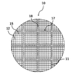
- FIG. 1 shows a schematic external view of the columnar honeycomb structure 10 according to the embodiment of the present invention.
- FIG. 2 shows a schematic cross-sectional view of the honeycomb structure 10 perpendicular to the axial direction.
- the honeycomb structure 10 is configured by joining a plurality of columnar honeycomb segments 17 via a bonding material layer 18.
- the honeycomb segment 17 includes an outer peripheral wall 11 and a porous partition wall 12 that is disposed inside the outer peripheral wall 11 and partitions a plurality of cells 15 that penetrate from one end face to the other end face to form a flow path.
- the outer shape of the honeycomb structure 10 is not particularly limited, but has a cylindrical end face (cylindrical shape), an oval-shaped columnar end face, and a polygonal end face (quadrangle, pentagon, hexagon, heptagon, octagon, etc.). It can have a columnar shape or the like.
- the size of the honeycomb structure 10 is not particularly limited, but the length in the central axial direction is preferably 40 to 500 mm. Further, for example, when the outer shape of the honeycomb structure 10 is columnar, the radius of the end face thereof is preferably 50 to 500 mm.
- the outer diameter of the honeycomb structure 10 may be the same as or different from the outer diameter of the honeycomb segment 17.
- a plurality of columnar honeycomb segments 17 having a quadrangular end face may be joined via a bonding material layer 18 to form a columnar honeycomb structure 10 having a quadrangular end face.
- a plurality of columnar honeycomb segments 17 having a quadrangular end face are joined via a joining material layer 18 to form a joined body having a quadrangular end face as a whole, and then the outer periphery of the joined body is ground to form an end face.
- the material of the partition wall 12 and the outer peripheral wall 11 of the honeycomb segment 17 is not particularly limited, but is usually formed of a ceramic material because it needs to be a porous body having a large number of pores.
- a ceramic material for example, cordierite, silicon carbide, silicon, aluminum titanate, silicon nitride, mullite, alumina, silicon-silicon carbide composites, silicon carbide-corgerite composites, especially silicon-silicon carbide composites or silicon carbide.
- Examples thereof include a sintered body as a main component.
- the term "silicon carbide-based" means that the honeycomb segment 17 contains silicon carbide in an amount of 50% by mass or more of the entire honeycomb segment 17.
- honeycomb segment 17 contains the silicon-silicon carbide composite as the main component means that the honeycomb segment 17 contains the silicon-silicon carbide composite (total mass) in an amount of 90% by mass or more of the entire honeycomb segment 17.
- the silicon-silicon carbide composite material contains silicon carbide particles as an aggregate and silicon as a binder for binding the silicon carbide particles, and a plurality of silicon carbide particles are formed between the silicon carbide particles. It is preferably bonded by silicon so as to form pores.
- the fact that the honeycomb segment 17 contains silicon carbide as a main component means that the honeycomb segment 17 contains silicon carbide (total mass) in an amount of 90% by mass or more of the entire honeycomb segment 17.
- the honeycomb segment 17 is more preferably having a high thermal conductivity from the viewpoint of heating the inside of the segment in a short time.
- the material for this purpose is preferably formed of at least one ceramic material selected from the group consisting of silicon carbide, silicon, and silicon nitride.
- the thermal conductivity of the ceramic material of the honeycomb segment 17 is preferably 3 W / mK or more, and more preferably 10 W / mK or more.
- the honeycomb segment 17 has a value of the coefficient of thermal expansion of the ceramic material as the coefficient of thermal expansion of the magnetic particles from the viewpoint of suppressing the thermal stress generated due to the difference in the coefficient of thermal expansion between the ceramic material and the magnetic particles during heating. Closer is more preferable.
- the material for this purpose is preferably formed of at least one selected from the group consisting of silicon carbide, silicon, and silicon nitride, and a ceramic material such as mullite and alumina.
- the coefficient of thermal expansion of the ceramic material of the honeycomb segment 17 is preferably 3 ⁇ 10 -6 or more. This coefficient of thermal expansion is measured with a thermal expansion meter, for example, in the range of room temperature to 800 ° C.
- the shape of the cell 15 of the honeycomb segment 17 is not particularly limited, but the cross section orthogonal to the central axis of the honeycomb segment 17 should be a polygon such as a triangle, a quadrangle, a pentagon, a hexagon, an octagon, a circle, or an ellipse. Is preferable, and other irregular shapes may be used.
- the thickness of the partition wall 12 of the honeycomb segment 17 is preferably 0.10 to 0.50 mm, and more preferably 0.25 to 0.45 mm in terms of ease of manufacture. For example, when it is 0.20 mm or more, the strength of the honeycomb structure 10 is further improved, and when it is 0.50 mm or less, the pressure loss can be further reduced when the honeycomb structure 10 is used as a filter. ..
- the thickness of the partition wall 12 is an average value measured by a method of observing a cross section in the central axis direction with a microscope.
- the porosity of the partition wall 12 constituting the honeycomb segment 17 is preferably 30 to 70%, and more preferably 40 to 65% in terms of ease of production.
- the porosity of the partition wall 12 is 30% or more, the pressure loss is likely to decrease, and when it is 70% or less, the strength of the honeycomb structure 10 can be maintained.
- the average pore diameter of the porous partition wall 12 is preferably 5 to 30 ⁇ m, more preferably 10 to 25 ⁇ m. When it is 5 ⁇ m or more, the pressure loss can be reduced when it is used as a filter, and when it is 30 ⁇ m or less, the strength of the honeycomb structure 10 can be maintained.
- the terms "average pore diameter” and “porosity” mean the average pore diameter and porosity measured by the mercury intrusion method.
- the cell density of the honeycomb segment 17 is preferably in the range of 5 to 93 cells / cm 2 , more preferably in the range of 5 to 63 cells / cm 2 , and in the range of 31 to 54 cells / cm 2. Is even more preferable.
- the cell density of the honeycomb segment 17 is 5 cells / cm 2 or more, the pressure loss is likely to decrease, and when it is 93 cells / cm 2 or less, the strength of the honeycomb structure 10 can be maintained.
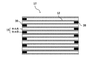
- the honeycomb segments 17 are alternately arranged with a plurality of cells A having one end face side open and having a mesh sealing portion 38 on the other end face, and cells A, respectively, and the other end face side is open.
- a plurality of cells B having a mesh sealing portion 39 on one end surface may be provided.
- the cells A and B are alternately arranged adjacent to each other with the partition wall 12 in between, and both end surfaces form a checkered pattern.
- the number, arrangement, shape, etc. of cells A and B are not limited, and can be appropriately designed as needed.
- Such a honeycomb structure 10 can be used as a filter (honeycomb filter) for purifying exhaust gas. When the honeycomb structure 10 is not used as a honeycomb filter, it is not necessary to provide the sealing portions 38 and 39.
- the honeycomb structure 10 of the present embodiment may have a catalyst supported on the surface of the partition wall 12 and / or in the pores of the partition wall 12.
- the type of catalyst is not particularly limited, and can be appropriately selected depending on the purpose and use of the honeycomb structure 10.
- a noble metal catalyst or a catalyst other than these can be mentioned.
- a noble metal catalyst such as platinum (Pt), palladium (Pd), or rhodium (Rh) is supported on the surface of the alumina pores, and a three-way catalyst containing a co-catalyst such as ceria or zirconia, an oxidation catalyst, or an alkali.
- a NO x storage reduction catalyst LNT catalyst
- earth metal and platinum as storage components of nitrogen oxide (NO x).
- catalysts that do not use noble metals include NO x selective reduction catalysts (SCR catalysts) containing copper-substituted or iron-substituted zeolites. Further, two or more kinds of catalysts selected from the group consisting of these catalysts may be used.
- the method of supporting the catalyst is also not particularly limited, and can be carried out according to the conventional method of supporting the catalyst on the honeycomb structure.
- the honeycomb structure 10 may have a breathable surface layer on at least a part of the surface of the partition wall 12.
- having breathability means that the permeability of the surface layer is 1.0 ⁇ 10 -13 m 2 or more. From the viewpoint of further reducing the pressure loss, the permeability is preferably 1.0 ⁇ 10 -12 m 2 or more. Since the surface layer has air permeability, it is possible to suppress the pressure loss of the honeycomb structure 10 caused by the surface layer.
- permability refers to a physical characteristic value calculated by the following formula (1), and is a value that is an index indicating the passing resistance when a predetermined gas passes through the object (partition wall 12). is there.
- C permeability (m 2 )
- F gas flow rate (cm 3 / s)
- T sample thickness (cm)
- V gas viscosity (dynes ⁇ sec / cm 2 ).
- D is the sample diameter (cm)
- P is the gas pressure (PSI).
- the partition wall 12 with the surface layer is cut out, the permeability is measured with the surface layer attached, and then the permability is measured with the surface layer scraped off, and the surface layer and the partition wall are measured.
- the permeability of the surface layer is calculated from the ratio of the thickness of the base material and the measurement results of these permeability.
- the porosity of the surface layer is preferably 50% or more, more preferably 60% or more, and even more preferably 70% or more. By having a porosity of 50% or more, pressure loss can be suppressed. However, if the porosity is too high, the surface layer becomes brittle and easily peels off, so it is preferably 90% or less.
- the difference between the mercury porosity of the sample having the surface layer and the base material and the mercury porosity of the base material only by scraping and removing only the surface layer is the difference between the surface layer. It is regarded as a mercury porosity curve, and the porosity of the surface layer is calculated from the scraped mass and the mercury porosity curve. SEM imaging may be performed, and the porosity of the surface layer may be calculated from the area ratio of the void portion and the solid portion by image analysis of the surface layer portion.
- the average pore diameter of the surface layer is preferably 10 ⁇ m or less, more preferably 5 ⁇ m or less, further preferably 4 ⁇ m or less, and particularly preferably 3 ⁇ m or less.
- the average pore diameter is preferably 10 ⁇ m or less, more preferably 5 ⁇ m or less, further preferably 4 ⁇ m or less, and particularly preferably 3 ⁇ m or less.
- the mercury porosi curve pore volume frequency
- the peak is taken as the average pore diameter.
- an SEM image of the cross section of the honeycomb structure 10 is taken, and the void portion and the solid portion are binarized by image analysis of the surface layer portion, 20 or more voids are randomly selected, and the average of the inscribed circles thereof is selected. May be the average pore diameter.
- the thickness of the surface layer is not particularly limited. However, in order to obtain the effect of the surface layer more remarkably, the thickness of the surface layer is preferably 10 ⁇ m or more. On the other hand, from the viewpoint of avoiding an increase in pressure loss, the thickness of the surface layer is preferably 80 ⁇ m or less. The thickness of the surface layer is more preferably 50 ⁇ m or less.
- the honeycomb structure 10 on which the surface layer is formed is cut in a direction perpendicular to the direction in which the cell 15 extends, and the thickness of the surface layer is measured from the cross section thereof. The average of the measured values of the thickness of the points can be taken.
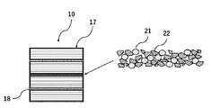
- FIG. 4 is a schematic cross-sectional view of the honeycomb structure 10 parallel to the axial direction.
- the bonding material constituting the bonding material layer 18 contains magnetic particles 21.
- an electric current is passed through the coil on the outer periphery of the honeycomb to raise the temperature of the magnetic particles 21 by induction heating, and the heat can raise the honeycomb temperature.
- the honeycomb structure 10 contains the magnetic particles 21 as a constituent component of the bonding material in the bonding material layer 18 instead of in the cell 15, it does not affect the pressure loss.
- the joining material constituting the joining material layer 18 for joining a plurality of honeycomb segments 17 may contain an aggregate 22, and at least a part of the aggregate 22 may be composed of magnetic particles 21. According to such a configuration, the magnetic material can be provided on the bonding material layer without increasing the volume of the bonding material layer, and the manufacturing efficiency is improved. Further, it is preferable that 40 to 100% by volume of the aggregate 22 is composed of magnetic particles 21, and more preferably 60 to 100% by volume of the aggregate. When the amount of the magnetic particles is 40 to 100% by volume, the contribution to the eddy current loss can be sufficiently obtained, and better heating characteristics can be obtained.
- the aggregate 22 is a ceramic containing at least one selected from the group consisting of cordierite, mullite, zircon, aluminum titanate, silicon carbide, silicon nitride, zirconia, spinel, indialite, sapphirine, corundum, and titania. It is preferable, and it is more preferable that the material is the same as that of the honeycomb segment 17. Silicon carbide is used as an aggregate because the conductive material contributes to the heating characteristics due to eddy current loss and the difference from magnetic particles in thermal expansion is relatively small. More preferable.
- the joining material constituting the joining material layer 18 preferably contains an inorganic binder in order to bond the aggregates to each other.
- an inorganic binder colloidal particles such as colloidal silica and colloidal alumina are preferably used.
- the bonding material constituting the bonding material layer 18 includes, for example, a dispersion medium (for example, water, etc.), and, if necessary, an inorganic binder, an organic binder, and a glutinating agent, in addition to the aggregate 22 containing the magnetic particles 21.
- a dispersion medium for example, water, etc.
- an inorganic binder for example, an organic binder, and a glutinating agent, in addition to the aggregate 22 containing the magnetic particles 21.
- Prepared by mixing additives such as foamed resin can be used.
- the addition of ceramic fibers is effective in imparting a stress relaxation function, and alumina fibers, magnesium silicate fibers and the like are preferably used from the viewpoint of complying with the REACH regulation.
- the organic binder include polyvinyl alcohol, methyl cellulose, CMC (carboxymethyl cellulose) and the like.
- the bonding material layer 18 of the honeycomb structure 10 is provided between all the adjacent honeycomb segments 17, and it is preferable that all the bonding material layers 18 include magnetic particles 21. According to such a configuration, the induction heating efficiency of the honeycomb structure 10 becomes better. Further, it is not necessary for all the bonding material layers 18 between the adjacent honeycomb segments 17 to contain the magnetic particles 21, and the bonding material layers 18 can be appropriately designed according to the desired induction heating efficiency.
- the bonding material layer 18 of the honeycomb structure 10 is provided along the axial direction of the honeycomb structure 10, but the aggregate 22 containing the magnetic material particles 21 is provided in the axial direction of the honeycomb structure 10. , It may be provided in the whole, or it may be provided in a part of the area.
- the aggregate 22 containing the magnetic particles 21 is provided on the entire axial direction of the honeycomb segment 17, the induction heating efficiency of the honeycomb segment 17 becomes better.
- the aggregate 22 containing the magnetic particles 21 is provided in a part of the region of the honeycomb segment 17 in the axial direction, for example, when the aggregate 22 is provided in the region on the inlet side of the gas flow path of the honeycomb segment 17, it is provided at the start position of the gas flow.
- the entire honeycomb segment 17 can be efficiently heated. Further, since soot tends to accumulate on the outlet side of the gas flow path of the honeycomb segment 17, if the aggregate 22 containing the magnetic particles 21 is provided in the region on the outlet side, the soot accumulated in the honeycomb segment 17 can be more effectively collected. Can be removed. Further, when the aggregate 22 containing the magnetic particles 21 is provided in a part of the honeycomb segment 17 in the axial direction, a coil provided on the outer periphery of the honeycomb structure 10 when the honeycomb structure 10 is used as an exhaust gas purifying device. Can be made compact.
- the bonding material layer 18 of the honeycomb structure 10 is provided so that the magnetic particles 21 and the aggregate are evenly mixed, but the present invention is not limited to this. That is, as shown in FIG. 10, in the bonding material layer 18, the magnetic particles 21 and the aggregate 22 may be unevenly distributed on one side along the axial direction of the honeycomb structure 10.
- the content of the magnetic particles 21 is preferably 30 to 70% by volume with respect to the bonding material layer 18.
- the content of the magnetic particles 21 is 30% by volume or more with respect to the bonding material layer 18, the induction heating efficiency of the honeycomb structure 10 becomes better.
- the content of the magnetic particles 21 is 70% by volume or less with respect to the bonding material layer 18, the effects of bonding strength and stress relaxation are likely to be exhibited, which is preferable.
- the magnetic particles 21 preferably have a Curie point of 450 ° C. or higher.
- the magnetic particle 21 has a Curie point of 450 ° C. or higher, it is possible to heat the catalyst supported on the honeycomb structure 10, and of course, the PM (particulate matter) collected in the cell 15 can be heated. It becomes easy to remove the combustion and regenerate the honeycomb structure filter.
- the magnetic material having a curry point of 450 ° C. or higher include the balance Co-20% by mass Fe, the balance Co-25% by mass Ni-4% by mass Fe, the balance Fe-15 to 35% by mass Co, and the balance Fe-.
- the magnetic particles 21 preferably have an intrinsic resistance value of 20 ⁇ cm or more at 25 ° C. According to such a configuration, the amount of heat generated by induction heating can be further increased.
- Examples of the magnetic material having an intrinsic resistance value of 20 ⁇ cm or more at 25 ° C. include the balance Fe-18 mass% Cr, the balance Fe-13 mass% Cr-2 mass% Si, and the balance Fe-20 mass% Cr-2 mass.
- the magnetic particle 21 preferably has a maximum magnetic permeability of 1000 or more. According to such a configuration, when the honeycomb structure 10 is dielectrically heated, the temperature is raised in a short time to a temperature at which moisture evaporates (about 100 ° C.) and further to a temperature at which the catalyst is activated (about 300 ° C.). Can be raised.
- the magnetic material having a maximum magnetic permeability of 1000 or more include the balance Fe-10% by mass Si-5% by mass Al, 49% by mass Co-49% by mass Fe-2% by mass V, and the balance Fe-36% by mass. There are Ni, the balance Fe-45% by mass Ni, the balance Fe-35% by mass Cr, the balance Fe-18% by mass Cr, and the like.
- the magnetic particles 21 are magnetized by a magnetic field, and the state of magnetization changes depending on the strength of the magnetic field. This is represented by the "magnetization curve".
- the magnetization curve may have a magnetic field H on the horizontal axis and a magnetic flux density B on the vertical axis (BH curve).
- the state in which no magnetic field is applied to the magnetic material is called the degaussing state and is represented by the origin O.
- the degaussing state When a magnetic field is applied, the magnetic flux density increases from the origin O and a saturated curve is drawn. This curve is the "initial magnetization curve".
- the slope of the straight line connecting the point on the initial magnetization curve and the origin is the "permeability".
- Permeability is a measure of the ease of magnetization of a magnetic material in the sense that a magnetic field permeates it.
- the magnetic permeability near the origin where the magnetic field is small is the “initial magnetic permeability”
- the maximum magnetic permeability on the initial magnetization curve is the “maximum magnetic permeability”.
- the honeycomb structure 10 may be provided with a coat layer 32 on the outer peripheral surface.
- the material constituting the coat layer 32 is not particularly limited, and various known coating materials can be appropriately used.
- the coating material may further contain colloidal silica, an organic binder, clay and the like.
- the organic binder is preferably used in an amount of 0.05 to 0.5% by mass, more preferably 0.1 to 0.2% by mass.
- the clay is preferably used in an amount of 0.2 to 2.0% by mass, more preferably 0.4 to 0.8% by mass.
- the coating material constituting the coat layer 32 may contain magnetic particles 21. More preferably, the coating material is a bonding material containing magnetic particles. According to such a configuration, the induction heating efficiency of the honeycomb structure 10 becomes better.
- the bonding material used for the coating material constituting the coat layer 32 the same material as described above can be used as the bonding material constituting the bonding material layer 18.
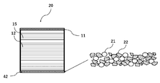
- FIG. 6A shows a schematic external view of the columnar honeycomb structure 20 according to another embodiment of the present invention.
- FIG. 6B shows a schematic cross-sectional view of the honeycomb structure 20 perpendicular to the axial direction.
- the honeycomb structure 20 is a porous partition wall 12 that is disposed inside the outer peripheral wall 11 and the outer peripheral wall 11 and partitions a plurality of cells 15 that penetrate from one end face to the other end face to form a flow path. And have.
- the honeycomb structure 20 further includes a coat layer 42 on the surface of the outer peripheral wall 11.
- the coating material constituting the coat layer 42 contains magnetic particles 21.
- the honeycomb structure 20 contains the magnetic particles 21 as a constituent component of the coating material in the coat layer 42, not in the cell 15, the pressure loss can be satisfactorily suppressed.
- FIG. 7 shows a schematic cross-sectional view of the honeycomb structure 20 parallel to the axial direction.
- the coating material constituting the coat layer 42 of the honeycomb structure 20 contains the aggregate 22 and at least a part of the aggregate 22 is similar to the bonding material of the bonding material layer 18 used in the honeycomb structure 10 described above. It may be composed of magnetic particles 21. Further, in the coat layer 42, the magnetic particles 21 may be uniformly distributed in the axial direction of the honeycomb structure 20, or may be provided in a part of the region of the honeycomb structure 20 in the axial direction. When the aggregate 22 containing the magnetic particles 21 is provided on the entire axial direction of the honeycomb structure 20, the heating efficiency of the honeycomb structure 20 by induction heating becomes better.
- the aggregate 22 containing the magnetic particles 21 is provided in a part of the region of the honeycomb structure 20 in the axial direction, for example, when the aggregate 22 is provided in the region on the inlet side of the gas flow path of the honeycomb structure 20, the gas flow starts. Since the gas heated at the position advances to the outlet side of the honeycomb structure 20, the entire honeycomb structure 20 can be efficiently heated. Further, since soot tends to accumulate on the outlet side of the gas flow path of the honeycomb structure 20, if the aggregate 22 containing the magnetic particles 21 is provided in the region on the outlet side, soot is more effectively accumulated in the honeycomb structure 20. Soot can be removed.
- the aggregate 22 containing the magnetic particles 21 is provided in a part of the honeycomb structure 20 in the axial direction, the aggregate 22 is provided on the outer periphery of the honeycomb structure 20 when the honeycomb structure 10 is used as an exhaust gas purifying device.
- the coil can be made compact. According to such a configuration, the magnetic material can be provided on the coat layer 42 without increasing the volume of the coat layer 42, and the production efficiency is improved.
- the coat layer 42 of the honeycomb structure 20 is provided so that the magnetic particles 21 and the aggregate are evenly mixed, but the coating layer 42 is not limited to this. That is, as shown in FIG. 11, in the coat layer 42, the magnetic particles 21 and the aggregate 22 may be unevenly distributed on one side along the axial direction of the honeycomb structure 20. As a result, when the honeycomb structure 20 is used as an exhaust gas purifying device, the coil provided on the outer periphery of the honeycomb structure 20 can be made compact.
- honeycomb structure manufacturing method The method for producing the honeycomb structure 10 according to the embodiment of the present invention will be described in detail.
- a honeycomb structure made of cordierite first, a cordierite-forming raw material is prepared as a material for clay. Since each component is blended in the cordierite-forming raw material so as to have the theoretical composition of the cordierite crystal, a silica source component, a magnesia source component, an alumina source component, and the like are blended. Of these, quartz and fused silica are preferably used as the silica source component, and the particle size of the silica source component is preferably 100 to 150 ⁇ m.
- magnesia source component examples include talc, magnesite and the like. Of these, talc is preferred. Talc is preferably contained in 37 to 43% by mass in the cordierite-forming raw material.
- the particle size (average particle size) of talc is preferably 5 to 50 ⁇ m, more preferably 10 to 40 ⁇ m.
- the magnesia (MgO) source component may contain Fe 2 O 3 , CaO, Na 2 O, K 2 O and the like as impurities.
- alumina source component those containing at least one of aluminum oxide and aluminum hydroxide are preferable in that there are few impurities.
- aluminum hydroxide is preferably contained in an amount of 10 to 30% by mass, and aluminum oxide is preferably contained in an amount of 0 to 20% by mass in the cordierite-forming raw material.
- a material (additive) for clay to be added to the cordierite raw material At least a binder and a pore-forming agent are used as additives. In addition to the binder and the pore-forming agent, a dispersant or a surfactant can be used.
- a substance that can be oxidized and removed by reacting with oxygen at a temperature equal to or lower than the firing temperature of cordierite, or a low melting point reactant having a melting point at a temperature equal to or lower than the firing temperature of corderite can be used.
- the substance that can be oxidatively removed include resins (particularly particulate resin) and graphite (particularly particulate graphite).
- the low melting point reactant at least one metal selected from the group consisting of iron, copper, zinc, lead, aluminum, and nickel, and alloys containing these metals as main components (for example, carbon steel in the case of iron). , Cast iron, stainless steel), or alloys containing two or more kinds of main components can be used.
- the low melting point reactant is preferably a powder-granular or fibrous iron alloy. Further, the particle size or fiber diameter (average diameter) is preferably 10 to 200 ⁇ m. Examples of the shape of the low melting point reactant include a spherical shape, a lozenge shape, a konpeito shape, and the like, and these shapes are preferable because the shape of the pores can be easily controlled.
- binder examples include hydroxypropylmethyl cellulose, methyl cellulose, hydroxyethyl cellulose, carboxymethyl cellulose, polyvinyl alcohol and the like.
- dispersant for example, dextrin, polyalcohol and the like can be mentioned.
- surfactant for example, fatty acid soap can be mentioned.
- the additive may be used alone or in combination of two or more.
- the prepared clay is molded into a honeycomb shape by an extrusion molding method, an injection molding method, a press molding method, etc. to obtain a raw honeycomb molded body. It is preferable to adopt an extrusion molding method because continuous molding is easy and, for example, cordierite crystals can be oriented.
- the extrusion molding method can be performed using an apparatus such as a vacuum clay kneader, a ram type extrusion molding machine, and a twin-screw type continuous extrusion molding machine.
- honeycomb molded body is dried and adjusted to a predetermined size to obtain a honeycomb dried body.
- the honeycomb molded body can be dried by hot air drying, microwave drying, dielectric drying, vacuum drying, vacuum drying, freeze drying and the like. Since the whole can be dried quickly and uniformly, it is preferable to perform drying by combining hot air drying and microwave drying or dielectric drying.
- honeycomb body is fired to produce a fired honeycomb body.
- each of the honeycomb fired bodies is used as a honeycomb segment, and the side surfaces of the plurality of honeycomb segments are joined and integrated by a joining material layer made of a joining material containing magnetic particles, and the plurality of honeycomb segments are joined.
- the honeycomb structure is in the state of being completed.
- the honeycomb structure in which the honeycomb segments are joined can be manufactured, for example, as follows.
- the bonding material is prepared by mixing, for example, a dispersion medium (for example, water, etc.) and, if necessary, additives such as a binder, a glue, and a foamed resin, in addition to the aggregate containing magnetic particles. can do.
- a dispersion medium for example, water, etc.
- additives such as a binder, a glue, and a foamed resin, in addition to the aggregate containing magnetic particles. can do.
- honeycomb segments are arranged adjacent to each other so that the side surfaces of the honeycomb segments face each other, and the adjacent honeycomb segments are crimped to each other and then heat-dried. In this way, a honeycomb structure in which the side surfaces of adjacent honeycomb segments are joined by a bonding material layer is produced.
- the material of the mask for preventing adhesion of the bonding material is not particularly limited, but for example, a synthetic resin such as polypropylene (PP), polyethylene terephthalate (PET), polyimide, or Teflon (registered trademark) can be preferably used.
- the mask preferably has an adhesive layer, and the material of the adhesive layer is preferably an acrylic resin, a rubber-based (for example, rubber containing natural rubber or synthetic rubber as a main component), or a silicon-based resin. preferable.
- an adhesive film having a thickness of 20 to 50 ⁇ m can be preferably used.
- the outer peripheral surface may be ground to remove the outer peripheral wall.
- a coating material is applied to the outer periphery of the honeycomb structure from which the outer peripheral wall has been removed in this manner in a later step to form a coat layer.
- a part of the outer peripheral wall may be ground and removed, and a coat layer may be formed on the portion by a coating material.
- FIG. 12 by impregnating the outer periphery of the honeycomb structure with magnetic particles as a slurry in a later step, the partition wall of the porous outer peripheral wall and the cell in the vicinity thereof can be obtained. The pores may be filled with magnetic particles.
- the honeycomb structure 30 in which the pores of the outer peripheral wall of the columnar honeycomb structure are filled with magnetic particles can be produced.
- the coating material when preparing the coating material, for example, it can be prepared using a biaxial rotary vertical mixer. Further, the coating material may further contain colloidal silica, an organic binder, clay and the like.
- the organic binder is preferably used in an amount of 0.05 to 0.5% by mass, more preferably 0.1 to 0.2% by mass. Further, the clay is preferably used in an amount of 0.2 to 2.0% by mass, more preferably 0.4 to 0.8% by mass.
- a coating material is applied to the outer peripheral surface of the honeycomb structure, and the applied coating material is dried to form a coat layer.
- the coating material is applied to the outer peripheral surface of the honeycomb structure, and the applied coating material is dried to form a coat layer.
- the honeycomb structure is placed on a turntable and rotated, and the coating material is discharged from the blade-shaped coating nozzle while the coating nozzle is applied along the outer peripheral portion of the honeycomb structure.
- a method of pressing and applying can be mentioned. With this configuration, the coating material can be applied with a uniform thickness. Further, the surface roughness of the formed outer peripheral coating is reduced, and it is possible to form an outer peripheral coating which is excellent in appearance and is not easily damaged by thermal shock.
- the method for drying the applied coating material is not particularly limited.
- the coating material is dried.
- a method for removing water and organic substances can be preferably used by holding the product in an electric furnace at 600 ° C. for 1 hour or longer.
- the catalyst When the catalyst is supported on the honeycomb structure, there is no particular limitation on the method of supporting the catalyst, and the catalyst can be supported according to the method of supporting the catalyst which is performed in the conventional method for producing the honeycomb structure.
- the exhaust gas purification device can be configured by using the honeycomb structure according to the embodiment of the present invention described above.
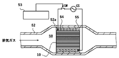
- FIG. 8 shows, as an example, a schematic view of the exhaust gas flow path of the exhaust gas purification device 50 in which the honeycomb structure 10 is incorporated.
- the exhaust gas purifying device 50 has a honeycomb structure 10 and a coil wiring 54 that spirally orbits the outer periphery of the honeycomb structure 10. Further, the exhaust gas purification device 50 has a metal pipe 52 for accommodating the honeycomb structure 10 and the coil wiring 54.
- the exhaust gas purification device 50 can be arranged in the enlarged diameter portion 52a of the metal pipe 52.
- the coil wiring 54 may be fixed in the metal tube 52 by the fixing member 55.
- the fixing member 55 is preferably a heat-resistant member such as a ceramic fiber.
- the honeycomb structure 10 may carry a catalyst.
- the coil wiring 54 is spirally wound around the outer circumference of the honeycomb structure 10. It is also assumed that two or more coil wirings 54 are used. An alternating current supplied from the alternating current power supply CS flows through the coil wiring 54 in response to the on (ON) of the switch SW, and as a result, a magnetic field that changes periodically is generated around the coil wiring 54.
- the on / off of the switch SW is controlled by the control unit 53.
- the control unit 53 can turn on the switch SW in synchronization with the start of the engine and allow an alternating current to flow through the coil wiring 54. It is also assumed that the control unit 53 turns on the switch SW regardless of the start of the engine (for example, in response to the operation of the heating switch pushed by the driver).
- the temperature of the honeycomb structure 10 rises according to a change in the magnetic field according to the alternating current flowing through the coil wiring 54. As a result, carbon fine particles and the like collected by the honeycomb structure 10 are burned.
- raising the temperature of the honeycomb structure 10 raises the temperature of the catalyst supported by the catalyst carrier contained in the honeycomb structure 10 and promotes the catalytic reaction.
- carbon monoxide (CO), oxide oxide (NO x ), and hydrocarbon (CH) are oxidized or reduced to carbon dioxide (CO 2 ), nitrogen (N 2 ), and water (H 2 O).
- Example 1 A columnar honeycomb segment made of cordierite having a square shape of 42 mm, a length of 85 mm, a partition wall thickness of 0.1 mm, and a distance between partition walls of about 1 mm was prepared. Next, a magnetic powder having an average particle size of 8 ⁇ m (composition: balance Fe-17 mass% Co-2 mass% Cr-1 mass% Mo) and silicon carbide powder having an average particle size of 6 ⁇ m were added at a mass ratio of 2: 1. After mixing, colloidal silica, alumina fiber having an average length of 200 ⁇ m, carboxymethyl cellulose, and water were further mixed to prepare a bonding material. The honeycomb segments were bonded with this bonding material to obtain a bonded body.
- a magnetic powder having an average particle size of 8 ⁇ m composition: balance Fe-17 mass% Co-2 mass% Cr-1 mass% Mo
- silicon carbide powder having an average particle size of 6 ⁇ m were added at a mass ratio of 2: 1.
- the outer circumference of the obtained bonded body was processed so as to have a cylindrical shape with a diameter of 82 mm to obtain a honeycomb structure.
- a heating test of the honeycomb structure was performed with an induction heating coil having a diameter of 100 mm, and the temperature of the end face of the honeycomb structure was measured with an infrared thermometer.
- the input power was 14 kW, the induction heating frequency was 30 kHz, and the temperature rising performance of the honeycomb structure was measured.
- FIG. 9 shows a graph showing the relationship between time (seconds) and temperature (° C.).
Landscapes
- Engineering & Computer Science (AREA)
- Chemical & Material Sciences (AREA)
- Chemical Kinetics & Catalysis (AREA)
- Combustion & Propulsion (AREA)
- Mechanical Engineering (AREA)
- General Engineering & Computer Science (AREA)
- Ceramic Engineering (AREA)
- Health & Medical Sciences (AREA)
- Organic Chemistry (AREA)
- Toxicology (AREA)
- Materials Engineering (AREA)
- Structural Engineering (AREA)
- Biomedical Technology (AREA)
- Environmental & Geological Engineering (AREA)
- Analytical Chemistry (AREA)
- General Chemical & Material Sciences (AREA)
- Oil, Petroleum & Natural Gas (AREA)
- Life Sciences & Earth Sciences (AREA)
- Sustainable Development (AREA)
- Inorganic Chemistry (AREA)
- Geology (AREA)
- Filtering Materials (AREA)
- Exhaust Gas Treatment By Means Of Catalyst (AREA)
- Processes For Solid Components From Exhaust (AREA)
- Catalysts (AREA)
- Exhaust Gas After Treatment (AREA)
- Filtering Of Dispersed Particles In Gases (AREA)
- Porous Artificial Stone Or Porous Ceramic Products (AREA)
- Ceramic Products (AREA)
Priority Applications (4)
| Application Number | Priority Date | Filing Date | Title |
|---|---|---|---|
| CN202080046761.4A CN114302764B (zh) | 2019-09-11 | 2020-05-01 | 蜂窝结构体及尾气净化装置 |
| DE112020003161.6T DE112020003161T5 (de) | 2019-09-11 | 2020-05-01 | Wabenstruktur und Abgasreinigungsvorrichtung |
| JP2021545111A JP7496829B2 (ja) | 2019-09-11 | 2020-05-01 | ハニカム構造体及び排気ガス浄化装置 |
| US17/646,181 US20220120204A1 (en) | 2019-09-11 | 2021-12-28 | Honeycomb structure and exhaust gas purifying device |
Applications Claiming Priority (2)
| Application Number | Priority Date | Filing Date | Title |
|---|---|---|---|
| JP2019-165761 | 2019-09-11 | ||
| JP2019165761 | 2019-09-11 |
Related Child Applications (1)
| Application Number | Title | Priority Date | Filing Date |
|---|---|---|---|
| US17/646,181 Continuation US20220120204A1 (en) | 2019-09-11 | 2021-12-28 | Honeycomb structure and exhaust gas purifying device |
Publications (1)
| Publication Number | Publication Date |
|---|---|
| WO2021049094A1 true WO2021049094A1 (ja) | 2021-03-18 |
Family
ID=74865631
Family Applications (1)
| Application Number | Title | Priority Date | Filing Date |
|---|---|---|---|
| PCT/JP2020/018451 Ceased WO2021049094A1 (ja) | 2019-09-11 | 2020-05-01 | ハニカム構造体及び排気ガス浄化装置 |
Country Status (5)
| Country | Link |
|---|---|
| US (1) | US20220120204A1 (https=) |
| JP (1) | JP7496829B2 (https=) |
| CN (1) | CN114302764B (https=) |
| DE (1) | DE112020003161T5 (https=) |
| WO (1) | WO2021049094A1 (https=) |
Cited By (1)
| Publication number | Priority date | Publication date | Assignee | Title |
|---|---|---|---|---|
| CN113663513A (zh) * | 2021-09-23 | 2021-11-19 | 大连海事大学 | 一种交变磁场强化催化剂的烟气脱硝方法 |
Citations (10)
| Publication number | Priority date | Publication date | Assignee | Title |
|---|---|---|---|---|
| JPH10130506A (ja) * | 1996-09-03 | 1998-05-19 | Toshiba Silicone Co Ltd | 導電性シリコーンゴムロール |
| JP2010013945A (ja) * | 2008-07-01 | 2010-01-21 | Toyota Industries Corp | 排ガス浄化装置 |
| JP2013203572A (ja) * | 2012-03-28 | 2013-10-07 | Ngk Insulators Ltd | ハニカム構造体 |
| JP2014189858A (ja) * | 2013-03-28 | 2014-10-06 | Nippon Steel & Sumitomo Metal | 還元鉄の製造方法および製造装置 |
| JP2016502245A (ja) * | 2012-11-30 | 2016-01-21 | エレクトリック パワー リサーチ インスチテュート インコーポレイテッド | 表面ドーピングによる電気的接触導電率の改善 |
| JP2017085143A (ja) * | 2012-05-14 | 2017-05-18 | 住友電気工業株式会社 | 超電導マグネット |
| JP2018083186A (ja) * | 2016-11-25 | 2018-05-31 | 小林 博 | 触媒作用をもたらす塗料の製造と触媒作用を発揮する積層体の形成 |
| JP2018143906A (ja) * | 2017-03-01 | 2018-09-20 | 日本碍子株式会社 | ハニカムフィルタ |
| JP2019060497A (ja) * | 2018-11-28 | 2019-04-18 | 日本ピラー工業株式会社 | 遊動環型メカニカルシール |
| JP2019091870A (ja) * | 2017-11-17 | 2019-06-13 | 日立金属株式会社 | センサ |
Family Cites Families (20)
| Publication number | Priority date | Publication date | Assignee | Title |
|---|---|---|---|---|
| US5403540A (en) * | 1990-10-29 | 1995-04-04 | Corning Incorporated | Heating of formed metal structure by induction |
| JPH0947664A (ja) * | 1995-05-31 | 1997-02-18 | Seda Giken:Kk | 触媒反応装置 |
| US6243041B1 (en) * | 2000-04-24 | 2001-06-05 | Motorola, Inc. | Antenna indexing and retaining mechanism |
| ATE481151T1 (de) * | 2003-02-28 | 2010-10-15 | Ibiden Co Ltd | Keramische wabenstruktur |
| EP1686108B1 (en) * | 2003-11-12 | 2011-09-14 | NGK Insulators, Ltd. | Honeycomb structure |
| KR100822246B1 (ko) * | 2005-04-07 | 2008-04-16 | 이비덴 가부시키가이샤 | 허니컴 구조체 |
| JP2008023429A (ja) * | 2006-07-19 | 2008-02-07 | Mazda Motor Corp | 排気ガス浄化用触媒 |
| WO2008026375A1 (en) * | 2006-08-31 | 2008-03-06 | Ngk Insulators, Ltd. | Process for producing honeycomb structure |
| JP5599208B2 (ja) * | 2010-03-19 | 2014-10-01 | 日本碍子株式会社 | ハニカム触媒体及び排ガス浄化装置 |
| EP2656901B1 (en) * | 2010-12-24 | 2020-04-29 | NGK Insulators, Ltd. | Honeycomb structure |
| US10835864B2 (en) | 2013-08-20 | 2020-11-17 | Advanced Technology Emission Solutions Inc. | Gaseous emissions treatment components and methods for manufacturing thereof |
| US9488085B2 (en) * | 2013-09-18 | 2016-11-08 | Advanced Technology Emission Solutions Inc. | Catalytic converter structures with induction heating |
| JP6114023B2 (ja) | 2012-12-18 | 2017-04-12 | 日本碍子株式会社 | 微粒子捕集フィルタ |
| JP6022985B2 (ja) * | 2013-03-29 | 2016-11-09 | 日本碍子株式会社 | ハニカム構造体 |
| US10918994B2 (en) * | 2013-09-18 | 2021-02-16 | Advanced Technology Emission Solutions Inc. | Induction heating apparatus and methods |
| US10132221B2 (en) | 2013-09-18 | 2018-11-20 | Advanced Technology Emission Solutions Inc. | Apparatus and method for gaseous emissions treatment with enhanced catalyst distribution |
| US9487448B2 (en) * | 2014-03-18 | 2016-11-08 | Ngk Insulators, Ltd. | Honeycomb structure |
| JP6483468B2 (ja) * | 2014-03-18 | 2019-03-13 | 日本碍子株式会社 | ハニカム構造体 |
| JP6742779B2 (ja) * | 2016-03-30 | 2020-08-19 | 日本碍子株式会社 | 還元剤噴射装置、及び排ガス処理装置 |
| CN114320542A (zh) * | 2018-02-28 | 2022-04-12 | 排放方案先进技术股份有限公司 | 感应加热装置和方法 |
-
2020
- 2020-05-01 WO PCT/JP2020/018451 patent/WO2021049094A1/ja not_active Ceased
- 2020-05-01 JP JP2021545111A patent/JP7496829B2/ja active Active
- 2020-05-01 CN CN202080046761.4A patent/CN114302764B/zh active Active
- 2020-05-01 DE DE112020003161.6T patent/DE112020003161T5/de active Pending
-
2021
- 2021-12-28 US US17/646,181 patent/US20220120204A1/en active Pending
Patent Citations (10)
| Publication number | Priority date | Publication date | Assignee | Title |
|---|---|---|---|---|
| JPH10130506A (ja) * | 1996-09-03 | 1998-05-19 | Toshiba Silicone Co Ltd | 導電性シリコーンゴムロール |
| JP2010013945A (ja) * | 2008-07-01 | 2010-01-21 | Toyota Industries Corp | 排ガス浄化装置 |
| JP2013203572A (ja) * | 2012-03-28 | 2013-10-07 | Ngk Insulators Ltd | ハニカム構造体 |
| JP2017085143A (ja) * | 2012-05-14 | 2017-05-18 | 住友電気工業株式会社 | 超電導マグネット |
| JP2016502245A (ja) * | 2012-11-30 | 2016-01-21 | エレクトリック パワー リサーチ インスチテュート インコーポレイテッド | 表面ドーピングによる電気的接触導電率の改善 |
| JP2014189858A (ja) * | 2013-03-28 | 2014-10-06 | Nippon Steel & Sumitomo Metal | 還元鉄の製造方法および製造装置 |
| JP2018083186A (ja) * | 2016-11-25 | 2018-05-31 | 小林 博 | 触媒作用をもたらす塗料の製造と触媒作用を発揮する積層体の形成 |
| JP2018143906A (ja) * | 2017-03-01 | 2018-09-20 | 日本碍子株式会社 | ハニカムフィルタ |
| JP2019091870A (ja) * | 2017-11-17 | 2019-06-13 | 日立金属株式会社 | センサ |
| JP2019060497A (ja) * | 2018-11-28 | 2019-04-18 | 日本ピラー工業株式会社 | 遊動環型メカニカルシール |
Cited By (1)
| Publication number | Priority date | Publication date | Assignee | Title |
|---|---|---|---|---|
| CN113663513A (zh) * | 2021-09-23 | 2021-11-19 | 大连海事大学 | 一种交变磁场强化催化剂的烟气脱硝方法 |
Also Published As
| Publication number | Publication date |
|---|---|
| US20220120204A1 (en) | 2022-04-21 |
| JP7496829B2 (ja) | 2024-06-07 |
| CN114302764B (zh) | 2023-12-26 |
| DE112020003161T5 (de) | 2022-03-24 |
| CN114302764A (zh) | 2022-04-08 |
| JPWO2021049094A1 (https=) | 2021-03-18 |
Similar Documents
| Publication | Publication Date | Title |
|---|---|---|
| US11614011B2 (en) | Pillar shaped honeycomb structure, exhaust gas purifying device, exhaust system, and method for producing honeycomb structure | |
| US12121886B2 (en) | Honeycomb structure and exhaust gas purifying device | |
| US20220118391A1 (en) | Honeycomb structure and exhaust gas purifying device | |
| US11369952B2 (en) | Honeycomb structure and exhaust gas purifying device | |
| US12209526B2 (en) | Honeycomb structure and exhaust gas purifying device | |
| US20220120203A1 (en) | Honeycomb structure and exhaust gas purifying device | |
| WO2020188973A1 (ja) | ハニカム構造体、排気ガス浄化装置及びハニカム構造体の製造方法 | |
| US12383852B2 (en) | Honeycomb structure and exhaust gas purifying device | |
| WO2021186792A1 (ja) | ハニカム構造体、排気ガス浄化触媒及び排気ガス浄化システム | |
| JP7496829B2 (ja) | ハニカム構造体及び排気ガス浄化装置 | |
| JP2024045347A (ja) | 触媒担体及び誘導加熱触媒システム |
Legal Events
| Date | Code | Title | Description |
|---|---|---|---|
| 121 | Ep: the epo has been informed by wipo that ep was designated in this application |
Ref document number: 20863591 Country of ref document: EP Kind code of ref document: A1 |
|
| ENP | Entry into the national phase |
Ref document number: 2021545111 Country of ref document: JP Kind code of ref document: A |
|
| 122 | Ep: pct application non-entry in european phase |
Ref document number: 20863591 Country of ref document: EP Kind code of ref document: A1 |