WO2021044657A1 - 回転軸カバーの支持ステー - Google Patents
回転軸カバーの支持ステー Download PDFInfo
- Publication number
- WO2021044657A1 WO2021044657A1 PCT/JP2020/014188 JP2020014188W WO2021044657A1 WO 2021044657 A1 WO2021044657 A1 WO 2021044657A1 JP 2020014188 W JP2020014188 W JP 2020014188W WO 2021044657 A1 WO2021044657 A1 WO 2021044657A1
- Authority
- WO
- WIPO (PCT)
- Prior art keywords
- cover
- mounting
- vehicle body
- support stay
- mounting portion
- Prior art date
- Legal status (The legal status is an assumption and is not a legal conclusion. Google has not performed a legal analysis and makes no representation as to the accuracy of the status listed.)
- Ceased
Links
Images



Classifications
-
- B—PERFORMING OPERATIONS; TRANSPORTING
- B60—VEHICLES IN GENERAL
- B60K—ARRANGEMENT OR MOUNTING OF PROPULSION UNITS OR OF TRANSMISSIONS IN VEHICLES; ARRANGEMENT OR MOUNTING OF PLURAL DIVERSE PRIME-MOVERS IN VEHICLES; AUXILIARY DRIVES FOR VEHICLES; INSTRUMENTATION OR DASHBOARDS FOR VEHICLES; ARRANGEMENTS IN CONNECTION WITH COOLING, AIR INTAKE, GAS EXHAUST OR FUEL SUPPLY OF PROPULSION UNITS IN VEHICLES
- B60K17/00—Arrangement or mounting of transmissions in vehicles
- B60K17/28—Arrangement or mounting of transmissions in vehicles characterised by arrangement, location, or type of power take-off
Definitions
- the present invention relates to a support stay that supports the rotating shaft cover.
- JPS62-48840U discloses a configuration in which a cover is provided to cover a rotating shaft provided in a vehicle for transmitting a driving force. This cover is fixed to the vehicle by welding the end to the vehicle body.
- the cover described in JPS62-48840U is in a cantilever support state in which only one end is fixed, not both ends. Therefore, due to the vibration of the engine and the vibration during running, the other end side of the cover sways, and the stress around the portion fixing the cover fluctuates. If such stress fluctuations continue for a long period of time, fatigue failure may occur around the fixed portion of the cover, and the cover may fall off.
- An object of the present invention is to suppress vibration of a rotating shaft cover that is cantilevered and supported.
- the support stays that cantileverly support the cover provided on the vehicle to cover the rotating shaft for transmitting the driving force include the cover, the cover mounting portion attached to the cover, and the cover mounting portion.
- a vehicle body mounting portion to be attached to the vehicle body of the vehicle and a connecting portion for connecting the cover mounting portion and the vehicle body mounting portion are provided, and the cover mounting portion is one end of the cover in the axial direction of the rotating shaft.
- the connecting portion has a first connecting portion that connects the first mounting portion and the vehicle body mounting portion, and a second connecting portion that connects the second mounting portion and the vehicle body mounting portion. ..
- FIG. 1 is a plan view of a mixer truck to which the support stay according to the first embodiment of the present invention is applied, as viewed from above.
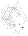
- FIG. 2 is a perspective view of a state in which the support stay according to the first embodiment of the present invention is applied to the mixer truck as viewed from above on the right rear side of the mixer truck.
- FIG. 3 is a developed view of the support stay according to the first embodiment of the present invention.
- FIG. 4 is a plan view of a state in which the support stay according to the first embodiment of the present invention is applied to a mixer truck as viewed from above.
- FIG. 5 is a developed view of a modified example of the support stay according to the first embodiment of the present invention.
- FIG. 6 is a perspective view of a state in which the support stay according to the second embodiment of the present invention is applied to the mixer truck as viewed from above on the right rear side of the mixer truck.
- the support stay 20 is a member that cantilever supports a cover provided on the vehicle to cover the rotating shaft for transmitting the driving force.
- the support stay 20 is provided to support the cover 14 that covers the drive shaft 8 which is the rotating shaft connected to the PTO shaft 9 of the engine 10 in the mixer truck 1 described later, which is a mounted vehicle. The case will be described.
- FIG. 1 is a plan view of the entire mixer truck 1 as viewed from above.
- the mixer truck 1 is a vehicle that transports so-called ready-mixed concrete (hereinafter, referred to as “ready-mixed concrete”) such as mortar and ready-mixed concrete put into the mixer drum 2.
- ready-mixed concrete so-called ready-mixed concrete
- the mixer truck 1 is a vehicle including a driver's cab 11 and a gantry 3 as a vehicle body fixed on a vehicle frame (not shown), and can be mounted on the gantry 3 to mount a ready-mixed truck.
- a mixer drum 2 and a drive device 4 for rotationally driving the mixer drum 2 are provided.
- the mixer drum 2 is a bottomed cylindrical container that is rotatably mounted on the gantry 3, and an opening 2a for loading and unloading the ready-mixed container is provided at the rear end thereof.
- the mixer drum 2 is mounted so as to be inclined so that its rotation axis O gradually rises from the front portion to the rear portion of the vehicle.
- Drum blades (not shown) are spirally arranged in the mixer drum 2 along the inner wall surface of the drum, and the drum blades rotate together with the mixer drum 2 to stir the ready-mixed drums loaded in the mixer drum 2. It is said.
- a hopper 16 is provided in the upper rear part of the opening 2a of the mixer drum 2.
- the ready-mixed concrete introduced into the mixer truck 1 at the ready-mixed concrete factory is guided to the opening 2a by the hopper 16.
- a flow guide and a chute 18 are provided in the lower rear portion of the opening 2a of the mixer drum 2.
- the ready-mixed rice discharged from the opening 2a is guided to the chute 18 by the flow guide, and is discharged in a predetermined direction by the chute 18.
- the mixer drum 2 is rotationally driven via a drive device 4 using a traveling engine 10 mounted on the mixer truck 1 as a drive source.
- the drive device 4 is a fluid pressure device that is driven by the rotation of the engine 10 and rotationally drives the mixer drum 2 by the fluid pressure of the working fluid.
- the rotation of the engine 10 is driven via a PTO shaft 9 (PTO: Power take-off) that constantly extracts power from the engine 10 and a drive shaft 8 as a rotation shaft that connects the PTO shaft 9 and the drive device 4. It is transmitted to the device 4. That is, the drive shaft 8 is provided in the mixer truck 1 to transmit the driving force for driving the driving device 4.
- PTO Power take-off
- the drive device 4 includes a hydraulic pump 5 that is driven by the engine 10 and discharges hydraulic oil as a hydraulic fluid, and a hydraulic motor 6 that is operated by the hydraulic oil supplied from the hydraulic pump 5 to rotationally drive the mixer drum 2.
- a hydraulic pump 5 that is driven by the engine 10 and discharges hydraulic oil as a hydraulic fluid
- a hydraulic motor 6 that is operated by the hydraulic oil supplied from the hydraulic pump 5 to rotationally drive the mixer drum 2.
- another incompressible fluid may be used as the hydraulic fluid.
- the hydraulic pump 5 is rotationally driven by the power constantly taken out from the engine 10 via the PTO shaft 9.
- the drive source for rotationally driving the hydraulic pump 5 via the drive shaft 8 is not limited to the traveling engine 10, and may be an auxiliary engine or an electric motor that is not used for traveling.
- the output shaft of the drive device 4, that is, the output shaft of the hydraulic motor 6, is connected to the rotation shaft O of the mixer drum 2 via the speed reducer 7. Therefore, it is possible to increase or decrease the rotation speed of the mixer drum 2 by increasing or decreasing the rotation speed of the hydraulic motor 6, and by switching the rotation direction of the hydraulic motor 6, the rotation direction of the mixer drum 2 is set to the forward rotation direction. It is possible to switch between a certain stirring direction and a discharge direction which is a reverse rotation direction.
- the mixer truck 1 having the above configuration is provided with a cover 14 that covers the drive shaft 8 in order to prevent the grease filled in the joint portion of the drive shaft 8 from scattering to the surroundings.
- the cover 14 is provided in the longitudinal direction along the axial direction of the drive shaft 8, and one end thereof is suspended below the frame 13 formed as a part of the gantry 3 via a support stay. It is fixed with.
- the frame 13 is a frame member that extends in the left-right direction of the mixer truck 1 between the drive device 4 and the driver's cab 11, and is bridged above the drive shaft 8.
- the cover 14 is in a cantilever support state in which only one end is fixed instead of both ends thereof in the longitudinal direction. Therefore, the vibration of the engine 10 and the vibration during traveling cause the other end side of the cover 14 to sway, so that the stress around the portion fixing the cover 14 to the vehicle body fluctuates. If such stress fluctuations continue for a long period of time, fatigue fracture may occur around the portion where the cover 14 is fixed, and as a result, the cover 14 may fall off.
- the cover 14 provided so as to cover the drive shaft 8 is easily affected by the vibration of the engine 10.
- the frame 13 to which the cover 14 is fixed is a part of the gantry 3 that supports the mixer drum 2, and is a part of the water tank. Since it is also used for holding and holding a spare tire, it is difficult to change the position of the cover 14 only for optimizing the support position.
- the cover 14 is cantilevered, the other end side of the cover 14 is suppressed from swinging.
- the cover 14 is supported by the support stay 20 having the above.
- FIG. 2 is a perspective view of the state in which the support stay 20 is attached to the mixer truck 1 as viewed from above on the right rear side of the mixer truck 1, and is a member such as a cover 14, a frame 13, and a drive shaft 8 other than the support stay 20. Is omitted.
- FIG. 3 is a developed view showing the support stay 20 formed of a single plate material in an unfolded manner
- FIG. 4 is a plan view of the state in which the support stay 20 is attached to the mixer truck 1 as viewed from above. is there.
- the cover 14 has a flat surface portion 14a to which the support stay 20 is attached, and the drive shaft 8 has one end 14b in the longitudinal direction facing the engine 10 side and the other end 14c facing the mixer drum 2 side. It is arranged along the axial direction of.
- the direction indicated by the arrow A indicates the axial direction of the drive shaft 8
- the direction indicated by the arrow B indicates the vertical direction of the mixer wheel 1.
- the support stay 20 that supports the cover 14 having the above shape includes a pair of cover mounting plates 31 that are attached to the flat surface portion 14a of the cover 14, and a vehicle body mounting plate 41 that is attached to the mounting surface 13a of the frame 13 as the vehicle body of the mixer truck 1. And a pair of connecting plates 51 as connecting portions for connecting the pair of cover mounting plates 31 and the vehicle body mounting plate 41, respectively.
- the cover mounting plate 31, the vehicle body mounting plate 41, and the connecting plate 51 are formed of a single plate material as shown by being developed in FIG.
- the cover mounting plate 31 is formed in a substantially rectangular shape, and as shown in FIG. 2, the first mounting hole 32 is formed at a position relatively close to the vehicle body mounting plate 41 when the support stay 20 is mounted on the cover 14.
- the first mounting hole 32 has two through holes, a second mounting hole 33 formed at a position separated from the first mounting hole 32 by a predetermined first distance L1 along the direction of arrow A, and the first mounting hole 32. It is attached to the cover 14 by a bolt (not shown) to be inserted and a bolt (not shown) to insert the second mounting hole 33.
- the cover mounting plate 31 includes a first mounting portion 31A, which is a portion of the cover mounting plate 31 where the first mounting hole 32 is provided, and a second mounting portion 31B, which is a portion where the second mounting hole 33 is provided. Is attached to the cover 14.
- a plurality of first mounting holes 32 and a plurality of second mounting holes 33 may be provided.
- the vehicle body mounting plate 41 is formed in a substantially rectangular shape, and is provided on a portion of the vehicle body mounting plate 41 facing the mounting surface 13a in a state where the support stay 20 is mounted on the mounting surface 13a of the frame 13 as shown in FIG. It has two mounting holes 42 and a lightening hole 43 provided for weight reduction, and is mounted on the frame 13 by a bolt (not shown) through which the mounting hole 42 is inserted.
- the vehicle body mounting plate 41 is attached to the frame 13 at the vehicle body mounting portion 41A, which is a portion of the vehicle body mounting plate 41 where the mounting holes 42 are provided.
- the number of mounting holes 42 provided in the vehicle body mounting portion 41A is not limited to two, and three or more may be provided.
- connection plate 51 is formed in a substantially right-angled triangular shape, has a lightening hole 54 provided for weight reduction like the vehicle body mounting plate 41, and is formed in the connection plate 51 by forming the lightening hole 54.
- the connection portion 52 extends diagonally linearly from the upper end of the vehicle body mounting plate 41 toward the tip of the cover mounting plate 31 on the second mounting portion 31B side to connect the second mounting portion 31B and the vehicle body mounting portion 41A.
- Two connection portions 53 and a third connection portion 55 extending in the direction of arrow A along the cover mounting plate 31 and connecting the first connection portion 52 and the second connection portion 53 are formed.
- the second connecting portion 53 is formed so as to have a first width W1 having a predetermined size in the axial direction of the drive shaft 8 indicated by the arrow A at a portion connected to the second mounting portion 31B.
- the portion connected to the mounting portion 41A is formed so as to have a second width W2 having a predetermined size in the vertical direction indicated by the arrow B.
- the size of the first width W1 is set so as to include a position where the second mounting hole 33 is provided from the other end 14c side of the second mounting portion 31B in the direction indicated by the arrow A, and the second width is set.
- the size of W2 is set to include a position where the mounting hole 42 is provided from the upper end of the vehicle body mounting portion 41A in the direction indicated by the arrow B.
- the cover mounting plate 31 and the vehicle body mounting plate 41 formed in a substantially rectangular shape as described above and the connecting plate 51 formed in a substantially right triangle shape are opposite sides of the vehicle body mounting plate 41.
- One adjacent side of the connecting plate 51 is connected to the other side of the connecting plate 51 via the first bent portion 61, and the cover mounting plate 31 is connected to the other adjacent side of the connecting plate 51 via the second bent portion 62.
- the support stay 20 has a first bent portion shown in FIG. 3 so that the angle formed by the vehicle body mounting plate 41 and the connecting plate 51 and the angle formed by the connecting plate 51 and the cover mounting plate 31 are approximately 90 °, respectively.
- the 61 and the second bent portion 62 are each bent into a valley fold to form a box shape as shown in FIG.
- the support stay 20 is formed only by bending from one plate material without requiring welding or the like, it is possible to suppress an increase in the manufacturing cost of the mixer truck 1 to which the support stay 20 is applied. ..
- the connecting plates 51 facing each other may be bent so as to be parallel to each other, but as shown in FIG. 4, the angle ⁇ formed by the vehicle body mounting plate 41 and the connecting plate 51 is slightly larger than 90 °.
- the temperature is 92 to 95 °, and the bending process is performed so that the distance between the connecting plates 51 facing each other gradually increases as the distance from the vehicle body mounting plate 41 increases.
- the positions of the first mounting hole 32 and the second mounting hole 33 are such that the installation line C1 provided with the first mounting hole 32 and the second mounting hole 33 is a pair of covers.
- the mounting plates 31 are set so as to be parallel to each other. Therefore, even if the distance between the connecting plates 51 facing each other is gradually increased as the distance from the vehicle body mounting plate 41 increases, the cover 14 faces the first mounting holes 32 and the second mounting holes 33.
- the mounting holes (not shown) formed on the side may be provided in parallel with the direction indicated by the arrow A. Therefore, it is possible to avoid an increase in the manufacturing cost of the cover 14.
- the bolt that inserts the first mounting hole 32 is connected to one end 14b of the cover 14, and the bolt that inserts the mounting hole 42 is connected to the frame 13, so that the cover 14 is cantilevered at one end 14b side by the support stay 20. It will be in a supported state.
- the support stay 20 is further covered by a bolt that inserts a second mounting hole 33 formed at a position separated from the first mounting hole 32 by a predetermined first distance L1 along the axial direction of the drive shaft 8. Combined with 14. Further, in this state, the second mounting portion 31B provided with the second mounting hole 33 and the vehicle body mounting portion 41A provided with the mounting hole 42 are inclined and linearly extend in the connecting plate 51 as described above. 2 It is connected by the connection part 53.
- the second connecting portion 53 that connects the second mounting portion 31B and the vehicle body mounting portion 41A functions as a so-called bumping member. Therefore, it is suppressed that the other end 14c of the cover 14 vibrates mainly in the vertical direction due to the vibration of the engine 10 or the like, as shown by the arrow B in FIG.
- the farthest part between the second mounting portion 31B and the vehicle body mounting portion 41A is linearly connected by the second connecting portion 53, and the second mounting is performed by the bumping function of the second connecting portion 53.
- the occurrence of vibration in the portion 31B is efficiently suppressed.
- the occurrence of vibration at the other end 14c of the cover 14 is also suppressed.
- the second connecting portion 53 is substantially orthogonal to the mounting surface of the vehicle body mounting portion 41A facing the mounting surface 13a of the frame 13 and substantially orthogonal to the mounting surface of the second mounting portion 31B facing the flat surface portion 14a of the cover 14. It is a plate-shaped portion extending in the direction of the plate, and is arranged so that the direction orthogonal to the plate thickness direction is along the direction indicated by the arrow A and the arrow B.
- the second connecting portion 53 arranged as described above has a higher rigidity.
- the direction orthogonal to the high plate thickness direction is arranged in the same direction as the vibration direction mainly generated at the other end 14c of the cover 14.
- the second connecting portion 53 arranged as described above is also connected to the first connecting portion 52 via the third connecting portion 55 extending in the arrow A direction along the cover mounting plate 31, the second connecting portion 53 is also connected.
- the rigidity of the second connecting portion 53 can be further improved by making the lightening hole 54 smaller.
- the rigidity in the twisting direction is improved by providing the third connecting portion 55 for connecting the first connecting portion 52 and the second connecting portion 53. Therefore, the vibration of the cover 14 can be efficiently suppressed.
- the first distance L1 which is the distance between the first mounting hole 32 and the second mounting hole 33 is at least one-third or more, more preferably half or more of the total length L2 of the cover 14. It is good to say. However, as the first distance L1 is increased, the support stay 20 becomes larger and heavier, and as a result, the maximum load capacity of the mixer truck 1 becomes smaller. Therefore, the first distance L1 is preferably about half of the total length L2 of the cover 14.
- the support stay 20 is connected to the frame 13 by a bolt that inserts the mounting hole 42, and is connected to one end 14b of the cover 14 by a bolt that inserts the first mounting hole 32, so that one end 14b side of the cover 14 is separated. I have and support it.
- the support stay 20 is formed at a position separated from the first mounting hole 32 by a predetermined first distance L1 along the axial direction of the drive shaft 8. It is further connected to the cover 14 by a bolt that inserts the hole 33. Further, the second mounting portion 31B provided with the second mounting hole 33 and the vehicle body mounting portion 41A provided with the mounting hole 42 are connected by a linearly formed second connecting portion 53 of the connecting plate 51. It has become.
- the cover 14 Since the second connecting portion 53 provided so as to connect the second mounting portion 31B and the vehicle body mounting portion 41A functions as a so-called bumping member, the cover 14 is supported by the support stay 20 having the above configuration. It is possible to prevent the other end 14c of the cover 14 from shaking due to the vibration of the engine 10 or the vibration during traveling.
- the first mounting hole 32 is formed in the cover mounting plate 31 together with the second mounting hole 33.
- the first mounting hole 32 may be provided in the second cover mounting plate 34, which is different from the cover mounting plate 31.
- the second cover mounting plate 34 which is the portion where the first mounting hole 32 is provided, corresponds to the first mounting portion
- the portion of the vehicle body mounting plate 41 extending in the vertical direction across the lightening hole 43 is the second portion. It corresponds to the first connection portion that connects the cover mounting plate 34 and the vehicle body mounting portion 41A.
- the support stay 20 is formed by the angle formed by the vehicle body mounting plate 41 and the connecting plate 51, the angle formed by the connecting plate 51 and the cover mounting plate 31, and the body mounting plate 41 and the second cover mounting plate 34.
- a third portion between the vehicle body mounting plate 41 and the second cover mounting plate 34 is provided so that the angles are approximately 90 °, respectively.
- Each of the bent portions 63 is bent into a valley fold to form a box shape as in the first embodiment.
- the mounting portions 31A, 31B, 41A of the support stay 20 are connected to the cover 14 and the frame 13 by bolts.
- the means for connecting the support stay 20 to the cover 14 and the frame 13 is not limited to bolts, and known bonding means such as rivet coupling and welding coupling may be used.
- the connecting plate 51 is formed in a substantially right-angled triangular shape, but the shape of the connecting plate 51 is not limited to a triangular shape having a right-angled portion, and a triangular shape having no right-angled portion or the like. It may have a quadrangular shape, and is appropriately changed according to the angle formed by the mounting surface 13a of the frame 13 and the flat surface portion 14a of the cover 14.
- the support stay 20 has a configuration in which the cover mounting plate 31 and the connecting plate 51 extend from both side portions of the vehicle body mounting plate 41.
- the support stay 20 may have a configuration in which the cover mounting plate 31 and the connecting plate 51 extend from only one side of the vehicle body mounting plate 41.
- the support stay 120 shown in FIG. 5 is mainly different from the support stay 20 according to the first embodiment in that it is composed of three members.
- the support stay 120 has three members, a first support member 130 attached to the cover 14 and the frame 13, and a pair of second support members 140 attached to the cover 14 and the frame 13.
- the first support member 130 is a plate-shaped member formed by bending at a substantially right angle so that the cross-sectional shape is substantially L-shaped, and the vehicle body mounting plate 131 mounted on the mounting surface 13a of the frame 13 and the cover 14 It has a cover mounting plate 135 that is mounted on the flat surface portion 14a.
- the vehicle body mounting plate 131 is formed in a substantially rectangular shape, and is provided on a portion of the vehicle body mounting plate 131 facing the mounting surface 13a in a state where the support stay 120 is mounted on the mounting surface 13a of the frame 13 as shown in FIG. It has two mounting holes 132 and a lightening hole 133 provided for weight reduction, and is mounted on the frame 13 by a bolt (not shown) through which the mounting hole 132 and the mounting hole 142 described later are inserted. That is, the vehicle body mounting plate 131 is attached to the frame 13 at the vehicle body mounting portion 131A, which is a portion of the vehicle body mounting plate 131 where the mounting holes 132 are provided.
- the cover mounting plate 135 is formed in a substantially rectangular shape, is arranged to face the cover 14 in a state where the support stay 120 is mounted on the cover 14 as shown in FIG. 6, and has two first mounting holes 136. ..
- the cover mounting plate 135 is attached to the cover 14 by a bolt (not shown) that inserts the first mounting hole 136. That is, the cover mounting plate 135 corresponds to the first mounting portion mounted on the cover 14.
- the cover mounting plate 135 corresponding to the first mounting portion formed in this way is connected to the vehicle body mounting portion 131A of the vehicle body mounting plate 131 at the portion of the vehicle body mounting plate 131 extending in the vertical direction with the lightening hole 133 interposed therebetween. ing. Therefore, the portion extending in the vertical direction across the lightening hole 133 corresponds to the first connecting portion.
- the second support member 140 includes a vehicle body mounting plate 141 attached to the frame 13, a cover mounting plate 144 attached to the flat surface portion 14a of the cover 14, and a connecting plate 147 connecting the vehicle body mounting plate 141 and the cover mounting plate 144. It is a plate-shaped member having.
- the vehicle body mounting plate 141 has a mounting hole 142, and is mounted on the frame 13 by a bolt (not shown) that inserts the mounting hole 142 and the mounting hole 132. That is, the vehicle body mounting plate 141 corresponds to the vehicle body mounting portion attached to the frame 13.
- the cover mounting plate 144 has a second mounting hole 145 provided at a position separated by a predetermined first distance L1 along the direction of arrow A from the first mounting hole 136, and is illustrated through which the second mounting hole 145 is inserted. It is attached to the cover 14 by a bolt that does not. That is, the cover mounting plate 144 corresponds to the second mounting portion mounted on the cover 14.
- connection plate 147 corresponds to the second connection portion.
- connection plate 147 corresponding to the second connection portion has a first width W1 having a predetermined size in the axial direction of the drive shaft 8 indicated by the arrow A at the portion connected to the cover mounting plate 144.
- the portion formed and connected to the vehicle body mounting plate 141 is formed so as to have a second width W2 having a predetermined size in the vertical direction indicated by the arrow B.
- the size of the first width W1 is set so as to include a position where the second mounting hole 145 is provided from the other end 14c side of the cover mounting plate 144 in the direction indicated by the arrow A, and the second width W2 The size of is set to include a position where the mounting hole 142 is provided from the upper end of the vehicle body mounting plate 141 in the direction indicated by the arrow B.
- the bolt that inserts the first mounting hole 136 is connected to one end 14b of the cover 14, and the bolt that inserts the mounting hole 132 and the mounting hole 142 is connected to the frame 13, so that the cover 14 has a support stay at one end 14b. It is cantilevered by 120.
- the support stay 120 is further covered by a bolt that inserts a second mounting hole 145 provided at a position separated from the first mounting hole 136 by a predetermined first distance L1 along the axial direction of the drive shaft 8. Combined with 14. Further, in this state, the cover mounting plate 144 provided with the second mounting hole 145 and the vehicle body mounting plate 141 provided with the mounting hole 142 are connected by the connecting plate 147 as described above.
- connection plate 147 that connects the cover mounting plate 144 and the vehicle body mounting plate 141 functions as a so-called bumping member. Therefore, it is suppressed that the other end 14c of the cover 14 mainly swings in the vertical direction due to the vibration of the engine 10 or the like, as shown by the arrow B in FIG.
- the end portion on the other end 14c side of the cover mounting plate 144 provided with the second mounting hole 145 which is the farthest portion in the direction indicated by the arrow A and the direction indicated by the arrow B, and the mounting hole. As described above, it is linearly connected to the upper end of the vehicle body mounting plate 141 on which the 142 is provided by the connecting plate 147.
- connection plate 147 extends substantially orthogonal to the mounting surface of the vehicle body mounting plate 141 facing the mounting surface 13a of the frame 13 and substantially orthogonal to the mounting surface of the cover mounting plate 144 facing the flat surface portion 14a of the cover 14. It is a plate-shaped portion, and is arranged so that the direction orthogonal to the plate thickness direction is along the direction indicated by the arrow A and the arrow B.
- the connecting plate 147 arranged as described above is a plate having high rigidity.
- the direction orthogonal to the thickness direction is arranged in the same direction as the vibration direction mainly generated at the other end 14c of the cover 14.
- the first distance L1 which is the distance between the first mounting hole 136 and the second mounting hole 145, is half or more of the total length L2 of the cover 14.
- the first distance L1 is preferably about half of the total length L2 of the cover 14.
- the support stay 120 is connected to the frame 13 by a bolt that inserts the mounting hole 132 and the mounting hole 142, and is connected to one end 14b of the cover 14 by a bolt that inserts the first mounting hole 136, whereby one end of the cover 14 is connected.
- the 14b side is cantilevered and supported.
- the support stay 120 is provided at a position separated from the first mounting hole 136 by a predetermined first distance L1 along the axial direction of the drive shaft 8. It is further coupled to the cover 14 by a bolt through which the hole 145 is inserted. Further, the cover mounting plate 144 provided with the second mounting hole 145 and the vehicle body mounting plate 141 provided with the mounting hole 142 are connected by a linearly formed connecting plate 147.
- connection plate 147 provided so as to connect the cover mounting plate 144 and the vehicle body mounting plate 141 functions as a so-called bumping member, the cover 14 is supported by the support stay 120 having the above configuration. It is possible to prevent the other end 14c of the engine 10 from shaking due to the vibration of the engine 10 or the vibration during running.
- connection plate 147 of the second support member 140 is substantially orthogonal to the vehicle body mounting plate 141 and substantially orthogonal to the cover mounting plate 144.
- the connecting plate 147 simply connects the lower end of the vehicle body mounting plate 141 and the end of the cover mounting plate 144 on the vehicle body mounting plate 141 side along the direction indicated by the arrow A. There may be.
- the vehicle body mounting portion 131A, the cover mounting plate 135, the vehicle body mounting plate 141, and the cover mounting plate 144 of the support stay 120 are connected to the cover 14 and the frame 13 by bolts.
- the means for connecting the support stay 120 to the cover 14 and the frame 13 is not limited to bolts, and known bonding means such as rivet coupling and welding coupling may be used.
- the first support member 130 is formed by bending at a substantially right angle so that the cross section is substantially L-shaped, but the shape of the first support member 130 is not limited to this.
- the angle formed by the mounting surface 13a of the frame 13 and the flat surface portion 14a of the cover 14 is appropriately changed.
- the angle formed by the vehicle body mounting plate 141 of the second support member 140 and the cover mounting plate 144 is appropriately changed according to the angle formed by the mounting surface 13a of the frame 13 and the flat surface portion 14a of the cover 14.
- the support stay 120 has a pair of second support members 140.
- the support stay 120 may have only one second support member 140.
- the support stays 20 and 120 include cover mounting portions 31A, 31B, 135, 144 attached to the cover 14, vehicle body mounting portions 41A, 131A, 141 attached to the frame 13 which is the vehicle body of the mixer car 1, and cover mounting portions 31A. , 31B, 135, 144 and connection portions 51, 131, 147 for connecting the vehicle body mounting portions 41A, 131A, 141, and the cover mounting portions 31A, 31B, 135, 144 are drive shafts 8 which are rotation shafts.
- First mounting portions 31A, 135 mounted closer to one end 14b of the cover 14 in the axial direction of the cover 14, and a predetermined number in the axial direction of the drive shaft 8 from the first mounting portions 31A, 135 to the other 14c side of the cover 14.
- It has second mounting portions 31B and 144 that are mounted on the cover 14 at a position separated by one distance L1, and the connecting portions 51, 131 and 147 are the first mounting portions 31A and 135 and the vehicle body mounting portions 41A and 131A. It has a first connection portion 52, 131 for connecting the above, and a second connection portion 53, 147 for connecting the second attachment portions 31B, 144 and the vehicle body attachment portions 41A, 141.
- the support stays 20 and 120 are covered by attaching the vehicle body mounting portions 41A, 131A and 141 to the frame 13 and mounting the first mounting portions 31A and 135 closer to one end 14b of the cover 14. 14 is cantilevered and supported.
- the support stays 20 and 120 are provided at positions separated from the first mounting portions 31A and 135 by a predetermined first distance L1 in the axial direction of the drive shaft 8.
- 2 Mounting portions 31B and 144 are mounted on the cover 14. Further, the second mounting portions 31B, 144 and the vehicle body mounting portions 41A, 141 are connected by the second connecting portions 53, 147.
- the support stays 20 and 120 having the above configuration are formed. By supporting the cover 14 by means of the cover 14, it is possible to prevent the other end 14c of the cover 14 from vibrating.
- the second connecting portions 53 and 147 are plate-shaped portions extending substantially orthogonal to the mounting surface of the vehicle body mounting portions 41A and 141 with respect to the frame 13 and substantially orthogonal to the mounting surface of the second mounting portions 31B and 144 with respect to the cover 14. Is.
- the second connecting portions 53 and 147 are plate-shaped portions, which are substantially orthogonal to the mounting surface of the vehicle body mounting portions 41A and 141 with respect to the frame 13 and substantially orthogonal to the mounting surface of the second mounting portions 31B and 144 with respect to the cover 14. It extends orthogonally. That is, in the second connecting portions 53 and 147, the direction orthogonal to the plate thickness direction having high rigidity is attached to the frame 13 of the vehicle body mounting portions 41A and 141 via the mounting surface of the second mounting portions 31B and 144 with respect to the cover 14. It is arranged so as to be in the same direction as the vibration of the cover 14 transmitted to the surface. By matching the vibration direction of the cover 14 with the direction orthogonal to the plate thickness direction of the second connecting portions 53 and 147 in this way, the vibration of the other end 14c of the cover 14 can be efficiently suppressed.
- cover mounting portions 31A and 31B, the vehicle body mounting portion 41A, and the connecting portion 51 are each formed by bending a single plate material.
- the cover mounting portions 31A and 31B, the vehicle body mounting portion 41A, and the connecting portion 51 are formed of a single plate material.
- the support stay 20 is formed only by bending from one plate material without requiring welding or the like, it is possible to suppress an increase in the manufacturing cost of the mixer truck 1 to which the support stay 20 is applied. it can.
- a pair of connecting portions 51 are provided with respect to the vehicle body mounting portion 41A, and the distance between the connecting portions 51 facing each other gradually increases as the distance from the vehicle body mounting portion 41A increases.
- first mounting portion 31A and the second mounting portion 31B are provided with respect to the vehicle body mounting portion 41A, and the pair of the first mounting portions 31A are each provided with the first mounting holes 32, and the pair of first mounting portions 31A
- a second mounting hole 33 is provided in each of the two mounting portions 31B, and the distance between the first mounting holes 32 and the distance between the second mounting holes 33 are the same.
- the positions of the first mounting hole 32 and the second mounting hole 33 are such that, as shown in FIG. 4, for example, a pair of installation lines C1 provided with the first mounting hole 32 and the second mounting hole 33 are provided.
- the cover mounting plates 31 are set so as to be parallel to each other. Therefore, even if the distance between the connecting plates 51 facing each other is gradually increased as the distance from the vehicle body mounting plate 41 increases, the cover 14 faces the first mounting holes 32 and the second mounting holes 33.
- the mounting holes (not shown) formed on the side may be provided in parallel with the direction indicated by the arrow A. Therefore, it is possible to avoid an increase in the manufacturing cost of the cover 14.
- the connecting portion 51 further has a third connecting portion 55 that connects the first connecting portion 52 and the second connecting portion 53.
- the first connection portion 52 and the second connection portion 53 are connected by the third connection portion 55. Therefore, even when the cover 14 vibrates so as to be twisted, the support stay 20 in the twisting direction is provided by providing the third connecting portion 55 for connecting the first connecting portion 52 and the second connecting portion 53. Since the rigidity is improved, the vibration of the cover 14 can be efficiently suppressed.
- the support stay 120 has a first support member 130 having a first mounting portion 135, a vehicle body mounting portion 131A, and a first connecting portion, and a second mounting portion 144, a vehicle body mounting portion 141, and a second connecting portion 147.
- a second support member 140 attached to the frame 13 together with the first support member 130.
- the support stay 120 includes a first support member 130 having a first mounting portion 135, a vehicle body mounting portion 131A, and a first connecting portion, and a second mounting portion 144, a vehicle body mounting portion 141, and a second connecting portion 147. It is formed by a second support member 140 which has and is attached to the frame 13 together with the first support member 130. Even when the support stay 120 is formed of a plurality of members in this way, the second connecting portion 147 provided so as to connect the second mounting portion 144 and the vehicle body mounting portion 141 is a so-called bumping member.
- the size of the predetermined first distance L1 is one-third or more of the length of the cover 14 in the axial direction of the drive shaft 8.
- the size of the predetermined first distance L1 is set to one-third or more of the length of the cover 14 in the axial direction of the drive shaft 8.
- the second mounting portions 31B and 144 and the vehicle body mounting portions 41A and 141 are connected. Since the provided second connecting portions 53 and 147 easily function as so-called support members, the other end 14c of the cover 14 vibrates by supporting the cover 14 by the support stays 20 and 120 having the above configuration. Can be suppressed.
- the support stays 20 and 120 support the cover 14 covering the drive shaft 8 which is the rotating shaft connected to the PTO shaft 9 of the engine 10 in the mixer truck 1 which is a mounted vehicle. It is provided in.
- the vehicle to which the support stay according to the present embodiment is applied is not limited to the mounted vehicle, and the support stay is a cover that covers a rotating shaft such as a drive shaft provided in the vehicle to transmit some driving force. It may be applied to any vehicle as long as it supports.
Landscapes
- Engineering & Computer Science (AREA)
- Chemical & Material Sciences (AREA)
- Combustion & Propulsion (AREA)
- Transportation (AREA)
- Mechanical Engineering (AREA)
- Arrangement And Driving Of Transmission Devices (AREA)
- Body Structure For Vehicles (AREA)
Abstract
支持ステー(20)は、カバー(14)に取り付けられるカバー取付部(31A,31B)と、車両の車体に取り付けられる車体取付部(41A)と、カバー取付部(31A,31B)と車体取付部(41A)とを接続する接続部(51)と、を備える。カバー取付部(31A,31B)は、カバー(14)の一方の端部(14b)寄りに取り付けられる第1取付部(31A)と、第1取付部(31A)からドライブシャフト(8)の軸方向に所定の第1距離(L1)だけ離れた位置においてカバー(14)に取り付けられる第2取付部(31B)と、を有し、接続部(51)は、第1取付部(31A)と車体取付部(41A)とを接続する第1接続部(52)と、第2取付部(31B)と車体取付部(41A)とを接続する第2接続部(53)と、を有する。
Description
本発明は、回転軸カバーを支持する支持ステーに関するものである。
JPS62-48840Uには、駆動力を伝達するために車両に設けられた回転軸を覆うためにカバーを設けた構成が開示されている。このカバーは端部が車体に溶接等されることによって車両に固定されている。
JPS62-48840Uに記載のカバーは、両端部ではなく一方の端部のみが固定された片持ち支持状態となっている。このため、エンジンの振動や走行時の振動によって、カバーの他方の端部側が揺れ動くことによりカバーを固定している部分周辺の応力が変動することになる。このような応力変動が長期間にわたって継続すると、やがてカバーの固定部周辺において疲労破壊が生じ、カバーが脱落するおそれがある。
本発明は、片持ち支持される回転軸カバーの振動を抑制することを目的とする。
本発明のある態様によれば、駆動力を伝達するために車両に設けられた回転軸を覆うカバーを片持ち支持する支持ステーは、前記カバーと、前記カバーに取り付けられるカバー取付部と、前記車両の車体に取り付けられる車体取付部と、前記カバー取付部と前記車体取付部とを接続する接続部と、を備え、前記カバー取付部は、前記回転軸の軸方向において前記カバーの一方の端部寄りに取り付けられる第1取付部と、前記第1取付部から前記カバーの他方側へ前記回転軸の軸方向に所定の距離だけ離れた位置において前記カバーに取り付けられる第2取付部と、を有し、前記接続部は、前記第1取付部と前記車体取付部とを接続する第1接続部と、前記第2取付部と前記車体取付部とを接続する第2接続部と、を有する。
以下、図面を参照して、本発明の実施形態について説明する。
<第1実施形態>
図1~3を参照して、本発明の第1実施形態に係る支持ステー20について説明する。
図1~3を参照して、本発明の第1実施形態に係る支持ステー20について説明する。
支持ステー20は、駆動力を伝達するために車両に設けられた回転軸を覆うカバーを片持ち支持する部材である。以下では、支持ステー20が、架装車両である後述のミキサ車1において、エンジン10のPTO軸9に連結される回転軸であるドライブシャフト8を覆うカバー14を支持するために設けられている場合について説明する。
まず、図1を参照して、本発明の第1実施形態に係る支持ステー20が適用される車両としてのミキサ車1の全体構成について説明する。図1は、ミキサ車1全体を上方から見た平面図である。
ミキサ車1は、ミキサドラム2内に投入されたモルタルやレディミクストコンクリート等のいわゆる生コンクリート(以下、「生コン」と称する。)を運搬する車両である。
ミキサ車1は、図1に示すように、運転室11と、図示しない車両フレーム上に固定された車体としての架台3と、を備える車両であり、架台3に搭載されて生コンを搭載可能なミキサドラム2と、ミキサドラム2を回転駆動する駆動装置4と、を備える。
ミキサドラム2は、架台3に回転可能に搭載される有底円筒形の容器であり、その後端には生コンの投入と排出とが行われる開口部2aが設けられる。ミキサドラム2は、その回転軸Oが車両の前部から後部に向かって徐々に高くなるように傾斜して搭載される。ミキサドラム2内には、図示しないドラムブレードがドラム内壁面に沿って螺旋状に配設されており、ミキサドラム2とともにドラムブレードが回転することによって、ミキサドラム2内に積載された生コンの攪拌等が行われる。
ミキサドラム2の開口部2aの後方上部には、ホッパ16が設けられる。生コン工場においてミキサ車1に投入される生コンは、ホッパ16によって開口部2aへと導かれる。ミキサドラム2の開口部2aの後方下部には、図示しないフローガイド及びシュート18が設けられる。開口部2aから排出される生コンは、フローガイドによってシュート18に導かれ、シュート18によって所定の方向に排出される。
ミキサドラム2は、ミキサ車1に搭載された走行用のエンジン10を駆動源として、駆動装置4を介して回転駆動される。駆動装置4は、エンジン10の回転によって駆動され、作動流体の流体圧によってミキサドラム2を回転駆動する流体圧装置である。
エンジン10の回転は、エンジン10から常時動力を取り出すPTO軸9(PTO:Power take-off)と、PTO軸9と駆動装置4とを連結する回転軸としてのドライブシャフト8と、を介して駆動装置4に伝達される。つまり、ドライブシャフト8は、ミキサ車1において、駆動装置4を駆動させる駆動力を伝達するために設けられている。
駆動装置4は、エンジン10によって駆動され作動流体としての作動油を吐出する油圧ポンプ5と、油圧ポンプ5から供給される作動油によって作動しミキサドラム2を回転駆動する油圧モータ6と、を有する。なお、駆動装置4では、作動流体として作動油ではなく、他の非圧縮性流体が用いられてもよい。
油圧ポンプ5は、PTO軸9を介してエンジン10から常時取り出される動力によって回転駆動される。なお、ドライブシャフト8を介して油圧ポンプ5を回転駆動させる駆動源としては、走行用のエンジン10に限定されず、走行に用いられない補機用のエンジンや電動モータであってもよい。
駆動装置4の出力軸、すなわち油圧モータ6の出力軸は、減速機7を介してミキサドラム2の回転軸Oに連結される。このため、油圧モータ6の回転速度を増減することによって、ミキサドラム2の回転速度を増減させることが可能であり、油圧モータ6の回転方向を切り換えることによって、ミキサドラム2の回転方向を正回転方向である撹拌方向と逆回転方向である排出方向とに切り換えることが可能である。
また、上記構成のミキサ車1には、ドライブシャフト8の継手部内に充填されたグリースが周囲に飛散することを防止するために、ドライブシャフト8を覆うカバー14が設けられている。
カバー14は、長手方向がドライブシャフト8の軸方向に沿って設けられており、その一端部が支持ステーを介して、架台3の一部として形成されたフレーム13の下方に吊り下げられた状態で固定されている。フレーム13は、駆動装置4と運転室11との間において、ミキサ車1の左右方向に延びて設けられるフレーム部材であり、ドライブシャフト8の上方に架け渡される。
ここで、従来では、カバー14は、長手方向において、その両端部ではなく一方の端部のみが固定された片持ち支持状態となっている。このため、エンジン10の振動や走行時の振動によって、カバー14の他方の端部側が揺れ動くことによりカバー14を車体に固定している部分周辺の応力が変動することになる。このような応力変動が長期間にわたって継続すると、やがてカバー14を固定している部分の周辺において疲労破壊が生じ、結果として、カバー14が脱落してしまうおそれがある。
特に、ドライブシャフト8の周辺は、エンジン10に近いことから、ドライブシャフト8を覆うように設けられるカバー14は、エンジン10の振動の影響を受けやすい。
このような振動を防止するには、カバー14の中央部を支持することが考えられるが、カバー14が固定されるフレーム13は、ミキサドラム2を支持する架台3の一部であり、水タンクの保持やスペアタイヤの保持などにも用いられることから、カバー14の支持位置を最適化するためだけにその位置を変更することは困難である。
また、カバー14の他方の端部側の揺動を防止するには、カバー14の両端を支持する構成とすることが考えられる。しかしながら、上述のミキサ車1のような架装車両では、ドライブシャフト8は、エンジン10から架装部に向かって配置されるため、カバー14の他方の端部は、架装部であるミキサドラム2や駆動装置4が配置される領域に臨むことになる。
このような架装部周辺にカバー14を支持するためのフレーム等の部材をさらに設けることは困難であるとともに、仮にフレーム等を追加することが可能であったとしても架装車両の製造コストの増大を招くとともに、架装車両の重量が増加し、最大積載量の低下を招くことになる。
このような従来の課題を解決するために、本実施形態では、カバー14が片持ち支持される場合であっても、カバー14の他方の端部側が揺れ動くことを抑制するために、後述の構成を有する支持ステー20によりカバー14を支持している。
次に、図2~4を参照し、支持ステー20の具体的な形状について説明する。図2は、支持ステー20がミキサ車1に取り付けられた状態をミキサ車1の右後方の上方から見た斜視図であり、カバー14、フレーム13及び支持ステー20以外のドライブシャフト8等の部材については省略して示している。図3は、単一の板材で形成される支持ステー20を展開して示した展開図であり、図4は、支持ステー20がミキサ車1に取り付けられた状態を上方から見た平面図である。
カバー14は、図2に示すように、支持ステー20が取り付けられる平面部14aを有し、長手方向の一端14bがエンジン10側に向かい、他端14cがミキサドラム2側に向かうようにドライブシャフト8の軸方向に沿って配置されている。なお、図2において、矢印Aで示される方向は、ドライブシャフト8の軸方向を示し、矢印Bで示される方向は、ミキサ車1の上下方向を示している。
上記形状のカバー14を支持する支持ステー20は、カバー14の平面部14aに取り付けられる一対のカバー取付板31と、ミキサ車1の車体としてのフレーム13の取付面13aに取り付けられる車体取付板41と、一対のカバー取付板31と車体取付板41とをそれぞれ接続する接続部としての一対の接続板51と、を有する。カバー取付板31と車体取付板41と接続板51とは、図3に展開して示されるように、1枚の板材により形成される。
カバー取付板31は、略矩形状に形成され、図2に示すように支持ステー20がカバー14に取り付けられた状態において、車体取付板41に比較的近い位置に形成される第1取付孔32と、第1取付孔32から矢印A方向に沿って所定の第1距離L1だけ離れた位置に形成される第2取付孔33と、の二つの貫通孔を有し、第1取付孔32を挿通する図示しないボルトと、第2取付孔33を挿通する図示しないボルトと、によってカバー14に取り付けられる。
つまり、カバー取付板31は、カバー取付板31のうち、第1取付孔32が設けられる部分である第1取付部31Aと、第2取付孔33が設けられる部分である第2取付部31Bと、においてカバー14に取り付けられる。このようにボルト等の締結部材を介してカバー14に取り付けられる部分である第1取付部31A及び第2取付部31Bがカバー取付部に相当する。なお、第1取付孔32及び第2取付孔33は、それぞれ複数設けられていてもよい。
車体取付板41は、略矩形状に形成され、図2に示すように支持ステー20がフレーム13の取付面13aに取り付けられた状態において、車体取付板41の取付面13aに対向する部分に設けられる2つの取付孔42と、軽量化のために設けられる肉抜き孔43と、を有し、取付孔42を挿通する図示しないボルトによってフレーム13に取り付けられる。
つまり、車体取付板41は、車体取付板41のうち、取付孔42が設けられる部分である車体取付部41Aにおいてフレーム13に取り付けられる。なお、車体取付部41Aに設けられる取付孔42の数は2つに限定されず、3つ以上設けられていてもよい。
接続板51は、略直角三角形状に形成され、車体取付板41と同様に、軽量化のために設けられる肉抜き孔54を有し、肉抜き孔54が形成されることで接続板51には、図2に示すように支持ステー20がカバー14及びフレーム13に取り付けられた状態において、車体取付板41に沿って上下方向に延び第1取付部31Aと車体取付部41Aとを接続する第1接続部52と、車体取付板41の上端からカバー取付板31の第2取付部31B側の先端に向かって斜めに直線状に延び第2取付部31Bと車体取付部41Aとを接続する第2接続部53と、カバー取付板31に沿って矢印A方向に延び第1接続部52と第2接続部53とを接続する第3接続部55と、が形成される。
また、第2接続部53は、第2取付部31Bと接続される部分では、矢印Aで示されるドライブシャフト8の軸方向に所定の大きさの第1幅W1を有するように形成され、車体取付部41Aと接続される部分では、矢印Bで示される上下方向に所定の大きさの第2幅W2を有するように形成される。第1幅W1の大きさは、矢印Aで示される方向において、第2取付部31Bの他端14c側の端部から第2取付孔33が設けられる位置を含むように設定され、第2幅W2の大きさは、矢印Bで示される方向において、車体取付部41Aの上方側の端部から取付孔42が設けられる位置を含むように設定される。
上述のように略矩形状に形成されたカバー取付板31及び車体取付板41と、略直角三角形状に形成された接続板51とは、図3に示されるように、車体取付板41の対辺に接続板51の一方の隣辺が第1折曲部61を介してそれぞれ接続され、接続板51の他方の隣辺には、カバー取付板31が第2折曲部62を介して接続される。
支持ステー20は、車体取付板41と接続板51とが成す角度及び接続板51とカバー取付板31とが成す角度がそれぞれ約90°となるように、図3に示される第1折曲部61及び第2折曲部62がそれぞれ谷折りに折り曲げ加工されることによって、図2に示されるような箱状に形成される。
このように支持ステー20は、溶接等を要することなく、1枚の板材から折り曲げ加工のみによって形成されるため、支持ステー20が適用されるミキサ車1の製造コストの上昇を抑制することができる。
なお、対向する接続板51は、互いに平行となるように折り曲げ加工されてもよいが、図4に示すように、車体取付板41と接続板51とが成す角度αを90°よりも若干大きく、例えば、92~95°とし、対向する接続板51の間隔が車体取付板41から離れるにつれて徐々に大きくなるように折り曲げ加工することが好ましい。
このように、対向する接続板51の間隔が車体取付板41から離れるにつれて大きくなるようにしておくことで、折り曲げ加工された複数の支持ステー20を、例えば車体取付板41を底面として重ねた状態で保管することが可能となる。これにより、支持ステー20の保管コストを低減することができる。
また、この際、第1取付孔32及び第2取付孔33の位置は、図4に示すように、第1取付孔32と第2取付孔33とが設けられる設置ラインC1が、一対のカバー取付板31間において互いに平行となるように設定されている。このため、対向する接続板51の間隔が車体取付板41から離れるにつれて徐々に大きくなるように形成される場合であっても、第1取付孔32及び第2取付孔33に対向してカバー14側に形成される図示しない取付孔は、矢印Aで示される方向と平行に設ければよいことになる。したがって、カバー14の製造コストが上昇してしまうことを回避することができる。
続いて、図2を参酌し、上記構成の支持ステー20によるカバー14の支持について説明する。
第1取付孔32を挿通するボルトがカバー14の一端14b寄りに結合され、取付孔42を挿通するボルトがフレーム13に結合されることによって、カバー14は、一端14b側が支持ステー20により片持ち支持された状態となる。
この状態において、支持ステー20は、第1取付孔32からドライブシャフト8の軸方向に沿って所定の第1距離L1だけ離れた位置に形成された第2取付孔33を挿通するボルトによってさらにカバー14に結合される。また、この状態において、第2取付孔33が設けられる第2取付部31Bと取付孔42が設けられる車体取付部41Aとは、上述のように、接続板51において傾斜して直線状に延びる第2接続部53により接続されている。
このように、第2取付部31Bと車体取付部41Aとを接続する第2接続部53は、いわゆる突支部材として機能する。このため、カバー14の他端14cがエンジン10等の振動によって、図2において矢印Bで示されるように、主に上下方向に振動することは抑制されることになる。
また、この状態において、矢印Aで示される方向及び矢印Bで示される方向において最も離れた部分である第2取付孔33が設けられる第2取付部31Bの他端14c側の端部と、取付孔42が設けられる車体取付部41Aの上方側の端部とは、上述のように、第2接続部53によって直線状に接続されている。
このように、第2取付部31Bと車体取付部41Aとの最も離れた部分間を第2接続部53により直線状に接続することにより、第2接続部53の突支機能によって、第2取付部31Bにおいて振動が生じることが効率的に抑制される。この結果、カバー14の他端14cにおいて振動が生じることも抑制されることになる。
また、第2接続部53は、フレーム13の取付面13aに対向する車体取付部41Aの取付面に略直交するとともにカバー14の平面部14aに対向する第2取付部31Bの取付面に略直交して延びる板状部であり、板厚方向に直交する方向が矢印A及び矢印Bで示される方向に沿うように配置されている。
ここで、一般的に、板厚部材は、板厚方向の剛性に比べて板厚方向に直交する方向の剛性が高いことから、上述のように配置された第2接続部53は、剛性が高い板厚方向に直交する方向が、カバー14の他端14cにおいて主に生じる振動方向と同じ方向に配置された状態となっている。
このようにカバー14の他端14cにおいて生じる振動の方向と第2接続部53の板厚方向に直交する方向とをほぼ一致させることにより、カバー14の振動を効率的に抑制することができる。
また、上述のように配置された第2接続部53は、カバー取付板31に沿って矢印A方向に延びる第3接続部55を介して第1接続部52とも接続されることから、第2接続部53が単独で設けられた場合と比較し、大幅に剛性が向上することで、カバー14の振動をさらに効率的に抑制することができる。なお、第2接続部53の剛性は、肉抜き孔54を小さくすることによってさらに向上させることが可能である。
また、カバー14がねじれるように振動した場合であっても、第1接続部52と第2接続部53とを接続する第3接続部55が設けられることで、ねじり方向における剛性が向上されるため、カバー14の振動を効率的に抑制することができる。
なお、振動抑制効果を高めるには、第1取付孔32と第2取付孔33との間隔である第1距離L1をカバー14の全長L2の少なくとも3分の1以上、より好ましくは、半分以上とすることがよい。しかし、第1距離L1を大きくする程、支持ステー20が大型化して重さが重くなり、結果として、ミキサ車1の最大積載量が小さくなってしまう。このため、第1距離L1は、カバー14の全長L2の半分程度とすることが好ましい。
以上の第1実施形態によれば、以下に示す効果を奏する。
支持ステー20は、取付孔42を挿通するボルトによりフレーム13に結合され、第1取付孔32を挿通するボルトによりカバー14の一端14b寄りに結合されることにより、カバー14の一端14b側を片持ち支持している。
このようにカバー14を片持ち支持した状態において、支持ステー20は、第1取付孔32からドライブシャフト8の軸方向に沿って所定の第1距離L1だけ離れた位置に形成された第2取付孔33を挿通するボルトによってさらにカバー14に結合される。また、第2取付孔33が設けられる第2取付部31Bと取付孔42が設けられる車体取付部41Aとは、接続板51の直線状に形成された第2接続部53により接続された状態となっている。
第2取付部31Bと車体取付部41Aとを接続するように設けられた第2接続部53は、いわゆる突支部材として機能することから、上記構成の支持ステー20によってカバー14を支持することにより、カバー14の他端14cがエンジン10の振動や走行時の振動によって揺れ動いてしまうことを抑制することができる。
次に、上記第1実施形態の変形例について説明する。
上記第1実施形態では、第1取付孔32は、第2取付孔33とともにカバー取付板31に形成されている。これに代えて、第1取付孔32は、図4に示すように、カバー取付板31とは別の第2カバー取付板34に設けられていてもよい。この場合、第1取付孔32が設けられる部分である第2カバー取付板34が第1取付部に相当し、肉抜き孔43を挟んで上下方向に延びる車体取付板41の部分が、第2カバー取付板34と車体取付部41Aとを接続する第1接続部に相当する。
また、この場合、支持ステー20は、車体取付板41と接続板51とが成す角度、接続板51とカバー取付板31とが成す角度及び車体取付板41と第2カバー取付板34とが成す角度がそれぞれ約90°となるように、図4に示される第1折曲部61及び第2折曲部62に加えて、車体取付板41と第2カバー取付板34との間の第3折曲部63がそれぞれ谷折りに折り曲げ加工されることによって、上記第1実施形態と同様に、箱状に形成される。
また、上記第1実施形態では、支持ステー20の各取付部31A,31B,41Aは、ボルトによって、カバー14及びフレーム13に結合されている。カバー14及びフレーム13に対して支持ステー20を結合させる手段はボルトに限定されず、リベット結合や溶接結合といった公知の結合手段が用いられてもよい。
また、上記第1実施形態では、接続板51は略直角三角形状に形成されているが、接続板51の形状は、直角部を有する三角形状に限定されず、直角部を有しない三角形状や四角形状であってもよく、フレーム13の取付面13aとカバー14の平面部14aとが成す角度に応じて適宜変更される。
また、上記第1実施形態では、支持ステー20は、車体取付板41の両側部からカバー取付板31及び接続板51が延びた構成となっている。これに代えて、支持ステー20は、車体取付板41の一方の側部のみからカバー取付板31及び接続板51が延びた構成となっていてもよい。
<第2実施形態>
次に、図5を参照して、本発明の第2実施形態に係る支持ステー120について説明する。以下では、第1実施形態と異なる点を中心に説明し、第1実施形態と同様の構成には、同一の符号を付し説明を省略する。
次に、図5を参照して、本発明の第2実施形態に係る支持ステー120について説明する。以下では、第1実施形態と異なる点を中心に説明し、第1実施形態と同様の構成には、同一の符号を付し説明を省略する。
図5に示される支持ステー120は、3つの部材により構成されている点で第1実施形態に係る支持ステー20と主に相違する。
支持ステー120は、カバー14とフレーム13とに取り付けられる第1支持部材130と、カバー14とフレーム13とに取り付けられる一対の第2支持部材140と、の3つの部材を有する。
第1支持部材130は、断面形状が略L字状となるように略直角に折り曲げて形成された板状部材であり、フレーム13の取付面13aに取り付けられる車体取付板131と、カバー14の平面部14aに取り付けられるカバー取付板135と、を有する。
車体取付板131は、略矩形状に形成され、図6に示すように支持ステー120がフレーム13の取付面13aに取り付けられた状態において、車体取付板131の取付面13aに対向する部分に設けられる2つの取付孔132と、軽量化のために設けられる肉抜き孔133と、を有し、取付孔132と後述の取付孔142を挿通する図示しないボルトによってフレーム13に取り付けられる。つまり、車体取付板131は、車体取付板131のうち、取付孔132が設けられる部分である車体取付部131Aにおいてフレーム13に取り付けられる。
カバー取付板135は、略矩形状に形成され、図6に示すように支持ステー120がカバー14に取り付けられた状態において、カバー14に対向配置されており、2つの第1取付孔136を有する。カバー取付板135は、第1取付孔136を挿通する図示しないボルトによってカバー14に取り付けられる。つまり、カバー取付板135は、カバー14に取り付けられる第1取付部に相当する。
このように形成された第1取付部に相当するカバー取付板135は、車体取付板131の車体取付部131Aと、肉抜き孔133を挟んで上下方向に延びる車体取付板131の部分において接続されている。したがって、肉抜き孔133を挟んで上下方向に延びる部分が第1接続部に相当する。
第2支持部材140は、フレーム13に取り付けられる車体取付板141と、カバー14の平面部14aに取り付けられるカバー取付板144と、車体取付板141とカバー取付板144とを接続する接続板147と、を有する板状部材である。
車体取付板141は、取付孔142を有し、取付孔142と取付孔132を挿通する図示しないボルトによってフレーム13に取り付けられる。つまり、車体取付板141は、フレーム13に取り付けられる車体取付部に相当する。
カバー取付板144は、第1取付孔136から矢印A方向に沿って所定の第1距離L1だけ離れた位置に設けられた第2取付孔145を有し、第2取付孔145を挿通する図示しないボルトによってカバー14に取り付けられる。つまり、カバー取付板144は、カバー14に取り付けられる第2取付部に相当する。
このように形成された車体取付部に相当する車体取付板141と、第2取付部に相当するカバー取付板144とは、接続板147により接続される。つまり、接続板147が第2接続部に相当する。
また、第2接続部に相当する接続板147は、カバー取付板144と接続される部分では、矢印Aで示されるドライブシャフト8の軸方向に所定の大きさの第1幅W1を有するように形成され、車体取付板141と接続される部分では、矢印Bで示される上下方向に所定の大きさの第2幅W2を有するように形成される。第1幅W1の大きさは、矢印Aで示される方向において、カバー取付板144の他端14c側の端部から第2取付孔145が設けられる位置を含むように設定され、第2幅W2の大きさは、矢印Bで示される方向において、車体取付板141の上方側の端部から取付孔142が設けられる位置を含むように設定される。
続いて、上記構成の支持ステー120によるカバー14の支持について説明する。
第1取付孔136を挿通するボルトがカバー14の一端14b寄りに結合され、取付孔132及び取付孔142を挿通するボルトがフレーム13に結合されることによって、カバー14は、一端14b側が支持ステー120により片持ち支持された状態となる。
この状態において、支持ステー120は、第1取付孔136からドライブシャフト8の軸方向に沿って所定の第1距離L1だけ離れた位置に設けられた第2取付孔145を挿通するボルトによってさらにカバー14に結合される。また、この状態において、第2取付孔145が設けられるカバー取付板144と取付孔142が設けられる車体取付板141とは、上述のように、接続板147により接続されている。
このように、カバー取付板144と車体取付板141とを接続する接続板147は、いわゆる突支部材として機能する。このため、カバー14の他端14cがエンジン10等の振動によって、図5において矢印Bで示されるように、主に上下方向に揺動することは抑制されることになる。
また、この状態において、矢印Aで示される方向及び矢印Bで示される方向において最も離れた部分である第2取付孔145が設けられるカバー取付板144の他端14c側の端部と、取付孔142が設けられる車体取付板141の上方側の端部とは、上述のように、接続板147によって直線状に接続されている。
このように、カバー取付板144と車体取付板141との最も離れた部分間を接続板147により直線状に接続することにより、接続板147の突支機能によって、カバー取付板144において振動が生じることが効率的に抑制される。この結果、カバー14の他端14cにおいて振動が生じることも抑制されることになる。
また、接続板147は、フレーム13の取付面13aに対向する車体取付板141の取付面に略直交するとともにカバー14の平面部14aに対向するカバー取付板144の取付面に略直交して延びる板状部であり、板厚方向に直交する方向が矢印A及び矢印Bで示される方向に沿うように配置されている。
ここで、一般的に、板厚部材は、板厚方向の剛性に比べて板厚方向に直交する方向の剛性が高いことから、上述のように配置された接続板147は、剛性が高い板厚方向に直交する方向が、カバー14の他端14cにおいて主に生じる振動方向と同じ方向に配置された状態となっている。
このようにカバー14の他端14cにおいて生じる振動の方向と接続板147の板厚方向に直交する方向とをほぼ一致させることにより、カバー14の振動を効率的に抑制することができる。
なお、振動抑制効果を高めるには、第1取付孔136と第2取付孔145との間隔である第1距離L1をカバー14の全長L2の半分以上とすることが好ましい。しかし、第1距離L1を大きくする程、支持ステー120が大型化して重さが重くなり、結果として、ミキサ車1の最大積載量が小さくなってしまう。このため、第1距離L1は、カバー14の全長L2の半分程度とすることが好ましい。
以上の第2実施形態によれば、以下に示す効果を奏する。
支持ステー120は、取付孔132及び取付孔142を挿通するボルトによりフレーム13に結合され、第1取付孔136を挿通するボルトによりカバー14の一端14b寄りに結合されることにより、カバー14の一端14b側を片持ち支持している。
このようにカバー14を片持ち支持した状態において、支持ステー120は、第1取付孔136からドライブシャフト8の軸方向に沿って所定の第1距離L1だけ離れた位置に設けられた第2取付孔145を挿通するボルトによってさらにカバー14に結合される。また、第2取付孔145が設けられるカバー取付板144と取付孔142が設けられる車体取付板141とは、直線状に形成された接続板147により接続された状態となっている。
カバー取付板144と車体取付板141とを接続するように設けられた接続板147は、いわゆる突支部材として機能することから、上記構成の支持ステー120によってカバー14を支持することにより、カバー14の他端14cがエンジン10の振動や走行時の振動によって揺れ動いてしまうことを抑制することができる。
次に、上記第2実施形態の変形例について説明する。
上記第2実施形態では、第2支持部材140の接続板147が車体取付板141に略直交するとともにカバー取付板144に略直交している。これに代えて、接続板147は、矢印Aで示される方向に沿って、車体取付板141の下方の端部とカバー取付板144の車体取付板141側の端部とを単に接続するものであってもよい。
また、上記第2実施形態では、支持ステー120の車体取付部131A、カバー取付板135、車体取付板141及びカバー取付板144は、ボルトによって、カバー14及びフレーム13に結合されている。カバー14及びフレーム13に対して支持ステー120を結合させる手段はボルトに限定されず、リベット結合や溶接結合といった公知の結合手段が用いられてもよい。
また、上記第2実施形態では、第1支持部材130は、断面が略L字状となるように略直角に折り曲げて形成されているが、第1支持部材130の形状はこれに限定されず、フレーム13の取付面13aとカバー14の平面部14aとが成す角度に応じて適宜変更される。同様に、第2支持部材140の車体取付板141とカバー取付板144とが成す角度もフレーム13の取付面13aとカバー14の平面部14aとが成す角度に応じて適宜変更される。
また、上記第2実施形態では、支持ステー120は、第2支持部材140を一対有している。これに代えて、支持ステー120は、第2支持部材140を1つだけ有する構成としてもよい。
以下、本発明の実施形態の構成、作用、及び効果をまとめて説明する。
支持ステー20,120は、カバー14に取り付けられるカバー取付部31A,31B,135,144と、ミキサ車1の車体であるフレーム13に取り付けられる車体取付部41A,131A,141と、カバー取付部31A,31B,135,144と車体取付部41A,131A,141とを接続する接続部51,131,147と、を備え、カバー取付部31A,31B,135,144は、回転軸であるドライブシャフト8の軸方向においてカバー14の一方の端部14b寄りに取り付けられる第1取付部31A,135と、第1取付部31A,135からカバー14の他方14c側へドライブシャフト8の軸方向に所定の第1距離L1だけ離れた位置においてカバー14に取り付けられる第2取付部31B,144と、を有し、接続部51,131,147は、第1取付部31A,135と車体取付部41A,131Aとを接続する第1接続部52,131と、第2取付部31B,144と車体取付部41A,141とを接続する第2接続部53,147と、を有する。
この構成では、支持ステー20,120は、車体取付部41A,131A,141がフレーム13に取り付けられ、第1取付部31A,135がカバー14の一方の端部14b寄りに取り付けられることにより、カバー14を片持ち支持している。
このようにカバー14を片持ち支持した状態において、支持ステー20,120は、第1取付部31A,135からドライブシャフト8の軸方向に所定の第1距離L1だけ離れた位置に設けられた第2取付部31B,144がカバー14に取り付けられる。また、第2取付部31B,144と車体取付部41A,141とは、第2接続部53,147により接続されている。
第2取付部31B,144と車体取付部41A,141とを接続するように設けられた第2接続部53,147は、いわゆる突支部材として機能することから、上記構成の支持ステー20,120によってカバー14を支持することにより、カバー14の他端14cが振動することを抑制することができる。
また、第2接続部53,147は、車体取付部41A,141のフレーム13に対する取付面に略直交するとともに第2取付部31B,144のカバー14に対する取付面に略直交して延びる板状部である。
この構成では、第2接続部53,147が板状部であり、車体取付部41A,141のフレーム13に対する取付面に略直交するとともに第2取付部31B,144のカバー14に対する取付面に略直交して延びている。つまり、第2接続部53,147は、剛性が高い板厚方向に直交する方向が、第2取付部31B,144のカバー14に対する取付面を介して車体取付部41A,141のフレーム13に対する取付面へと伝達されるカバー14の振動の方向と同じ方向となるように配置されている。このようにカバー14の振動方向と第2接続部53,147の板厚方向に直交する方向とを一致させることにより、カバー14の他端14cの振動を効率的に抑制することができる。
また、カバー取付部31A,31B、車体取付部41A、及び、接続部51は、単一の板材を折り曲げることによりそれぞれ形成される。
この構成では、カバー取付部31A,31B、車体取付部41A、及び、接続部51が、単一の板材により形成される。このように、支持ステー20は、溶接等を要することなく、1枚の板材から折り曲げ加工のみによって形成されるため、支持ステー20が適用されるミキサ車1の製造コストの上昇を抑制することができる。
また、接続部51は、車体取付部41Aに対して一対設けられ、対向する接続部51の間隔は、車体取付部41Aから離れるにつれて徐々に大きくなる。
このように、対向する接続板51の間隔が車体取付板41から離れるにつれて大きくなるようにしておくことで、折り曲げ加工された複数の支持ステー20を、例えば車体取付板41を底面として重ねた状態で保管することが可能となる。これにより、支持ステー20の保管コストを低減することができる。
また、第1取付部31A及び第2取付部31Bは、車体取付部41Aに対してそれぞれ一対設けられ、一対の第1取付部31Aには、それぞれ第1取付孔32が設けられ、一対の第2取付部31Bには、それぞれ第2取付孔33が設けられ、第1取付孔32間の間隔と、第2取付孔33間の間隔と、は同じである。
この構成では、第1取付孔32及び第2取付孔33の位置は、例えば図4に示されるように、第1取付孔32と第2取付孔33とが設けられる設置ラインC1が、一対のカバー取付板31間において互いに平行となるように設定されている。このため、対向する接続板51の間隔が車体取付板41から離れるにつれて徐々に大きくなるように形成される場合であっても、第1取付孔32及び第2取付孔33に対向してカバー14側に形成される図示しない取付孔は、矢印Aで示される方向と平行に設ければよいことになる。したがって、カバー14の製造コストが上昇してしまうことを回避することができる。
また、接続部51は、第1接続部52と第2接続部53とを接続する第3接続部55をさらに有する。
この構成では、第1接続部52と第2接続部53とが第3接続部55により接続される。このため、カバー14がねじれるように振動した場合であっても、第1接続部52と第2接続部53とを接続する第3接続部55が設けられることで、ねじり方向における支持ステー20の剛性が向上されるため、カバー14の振動を効率的に抑制することができる。
また、支持ステー120は、第1取付部135、車体取付部131A及び第1接続部を有する第1支持部材130と、第2取付部144、車体取付部141及び第2接続部147を有し、第1支持部材130とともにフレーム13に取り付けられる第2支持部材140と、により形成される。
この構成では、支持ステー120は、第1取付部135、車体取付部131A及び第1接続部を有する第1支持部材130と、第2取付部144、車体取付部141及び第2接続部147を有し、第1支持部材130とともにフレーム13に取り付けられる第2支持部材140と、により形成される。このように支持ステー120が複数の部材で形成される場合であっても、第2取付部144と車体取付部141とを接続するように設けられた第2接続部147は、いわゆる突支部材として機能することから、上記構成の支持ステー120によってカバー14を支持することにより、カバー14の他端14cが振動することを抑制することができる。
また、所定の第1距離L1の大きさは、ドライブシャフト8の軸方向におけるカバー14の長さの3分の1以上である。
この構成では、所定の第1距離L1の大きさが、ドライブシャフト8の軸方向におけるカバー14の長さの3分の1以上に設定される。このように、所定の第1距離L1の大きさをカバー14の長さの3分の1以上とすることで、第2取付部31B,144と車体取付部41A,141とを接続するように設けられた第2接続部53,147は、いわゆる突支部材として機能し易くなることから、上記構成の支持ステー20,120によってカバー14を支持することにより、カバー14の他端14cが振動することを抑制することができる。
以上、本発明の実施形態について説明したが、上記実施形態は本発明の適用例の一部を示したに過ぎず、本発明の技術的範囲を上記実施形態の具体的構成に限定する趣旨ではない。
例えば、上記各実施形態では、支持ステー20,120が、架装車両であるミキサ車1において、エンジン10のPTO軸9に連結される回転軸であるドライブシャフト8を覆うカバー14を支持するために設けられている。本実施形態に係る支持ステーが適用される車両は架装車両に限定されるものではなく、支持ステーは、何らかの駆動力を伝達するために車両に設けられたドライブシャフト等の回転軸を覆うカバーを支持していれば、どのような車両に適用されるものであってもよい。
本願は2019年9月4日に日本国特許庁に出願された特願2019-161619に基づく優先権を主張し、この出願の全ての内容は参照により本明細書に組み込まれる。
Claims (8)
- 駆動力を伝達するために車両に設けられた回転軸を覆うカバーを片持ち支持する支持ステーであって、
前記カバーと、
前記カバーに取り付けられるカバー取付部と、
前記車両の車体に取り付けられる車体取付部と、
前記カバー取付部と前記車体取付部とを接続する接続部と、を備え、
前記カバー取付部は、前記回転軸の軸方向において前記カバーの一方の端部寄りに取り付けられる第1取付部と、前記第1取付部から前記カバーの他方側へ前記回転軸の軸方向に所定の距離だけ離れた位置において前記カバーに取り付けられる第2取付部と、を有し、
前記接続部は、前記第1取付部と前記車体取付部とを接続する第1接続部と、前記第2取付部と前記車体取付部とを接続する第2接続部と、を有する支持ステー。 - 請求項1に記載の支持ステーであって、
前記第2接続部は、前記車体取付部の前記車体に対する取付面に略直交するとともに前記第2取付部の前記カバーに対する取付面に略直交して延びる板状部である支持ステー。 - 請求項1または2に記載の支持ステーであって、
前記カバー取付部、前記車体取付部、及び、前記接続部は、単一の板材を折り曲げることによりそれぞれ形成される支持ステー。 - 請求項3に記載の支持ステーであって、
前記接続部は、前記車体取付部に対して一対設けられ、
対向する前記接続部の間隔は、前記車体取付部から離れるにつれて徐々に大きくなる支持ステー。 - 請求項4に記載の支持ステーであって、
前記第1取付部及び前記第2取付部は、前記車体取付部に対してそれぞれ一対設けられ、
一対の前記第1取付部には、それぞれ第1取付孔が設けられ、
一対の前記第2取付部には、それぞれ第2取付孔が設けられ、
前記第1取付孔間の間隔と、前記第2取付孔間の間隔と、は同じである支持ステー。 - 請求項1から5の何れか1つに記載の支持ステーであって、
前記接続部は、前記第1接続部と前記第2接続部とを接続する第3接続部をさらに有する支持ステー。 - 請求項1または2に記載の支持ステーであって、
前記第1取付部、前記車体取付部及び前記第1接続部を有する第1支持部材と、
前記第2取付部、前記車体取付部及び前記第2接続部を有し、前記第1支持部材とともに前記車体に取り付けられる第2支持部材と、により形成される支持ステー。 - 請求項1から7の何れか1つに記載の支持ステーであって、
前記所定の距離の大きさは、前記回転軸の軸方向における前記カバーの長さの3分の1以上である支持ステー。
Applications Claiming Priority (2)
| Application Number | Priority Date | Filing Date | Title |
|---|---|---|---|
| JP2019-161619 | 2019-09-04 | ||
| JP2019161619A JP7291038B2 (ja) | 2019-09-04 | 2019-09-04 | 回転軸カバーの支持ステー |
Publications (1)
| Publication Number | Publication Date |
|---|---|
| WO2021044657A1 true WO2021044657A1 (ja) | 2021-03-11 |
Family
ID=74848877
Family Applications (1)
| Application Number | Title | Priority Date | Filing Date |
|---|---|---|---|
| PCT/JP2020/014188 Ceased WO2021044657A1 (ja) | 2019-09-04 | 2020-03-27 | 回転軸カバーの支持ステー |
Country Status (2)
| Country | Link |
|---|---|
| JP (1) | JP7291038B2 (ja) |
| WO (1) | WO2021044657A1 (ja) |
Citations (4)
| Publication number | Priority date | Publication date | Assignee | Title |
|---|---|---|---|---|
| JPS5586124U (ja) * | 1978-12-12 | 1980-06-13 | ||
| JPS56118128U (ja) * | 1980-02-08 | 1981-09-09 | ||
| JPS56158326U (ja) * | 1980-04-26 | 1981-11-26 | ||
| JPS6248840U (ja) * | 1985-09-17 | 1987-03-26 |
-
2019
- 2019-09-04 JP JP2019161619A patent/JP7291038B2/ja active Active
-
2020
- 2020-03-27 WO PCT/JP2020/014188 patent/WO2021044657A1/ja not_active Ceased
Patent Citations (4)
| Publication number | Priority date | Publication date | Assignee | Title |
|---|---|---|---|---|
| JPS5586124U (ja) * | 1978-12-12 | 1980-06-13 | ||
| JPS56118128U (ja) * | 1980-02-08 | 1981-09-09 | ||
| JPS56158326U (ja) * | 1980-04-26 | 1981-11-26 | ||
| JPS6248840U (ja) * | 1985-09-17 | 1987-03-26 |
Also Published As
| Publication number | Publication date |
|---|---|
| JP7291038B2 (ja) | 2023-06-14 |
| JP2021037899A (ja) | 2021-03-11 |
Similar Documents
| Publication | Publication Date | Title |
|---|---|---|
| CN104619527B (zh) | 轮内电动机驱动装置的悬架结构 | |
| JP4321199B2 (ja) | 駆動モータの取付構造 | |
| JP5800214B2 (ja) | 電気自動車のパワーユニット懸架構造 | |
| JP5747270B2 (ja) | 自動車後部における重要保安部品の設置構造 | |
| EP2097619B1 (en) | Vehicle engine structure | |
| JP7584020B2 (ja) | 車体後部構造 | |
| JP2010274724A (ja) | 車体側部構造 | |
| JP5539523B2 (ja) | エンジンマウント支持構造 | |
| CN109515143A (zh) | 电动车辆 | |
| JP2016203902A (ja) | 車両の配線固定構造 | |
| US9616930B2 (en) | Suspension frame structure | |
| WO2021044657A1 (ja) | 回転軸カバーの支持ステー | |
| JP5488506B2 (ja) | 車両の下部車体構造 | |
| JP7285684B2 (ja) | パワーユニット懸架構造 | |
| CN102187037A (zh) | 具有位于振动碾上的振动隔离装置的滑移装载机 | |
| WO2005028117A1 (ja) | 移動式木材破砕機 | |
| JP6827269B2 (ja) | ミキサ車 | |
| JP2008179258A (ja) | ステアリング支持部構造 | |
| JP7275549B2 (ja) | 車両用パワーユニットの支持構造 | |
| JP5977297B2 (ja) | 車体構造 | |
| JP2002331965A (ja) | 自動車の車体前部構造 | |
| JP2004359125A (ja) | 車体のフロア構造 | |
| JP7373130B2 (ja) | 車両後部構造 | |
| KR101163802B1 (ko) | 차량용 리어 크로스멤버의 보강구조체 | |
| KR100568735B1 (ko) | 서브프레임 마운팅 구조 |
Legal Events
| Date | Code | Title | Description |
|---|---|---|---|
| 121 | Ep: the epo has been informed by wipo that ep was designated in this application |
Ref document number: 20860578 Country of ref document: EP Kind code of ref document: A1 |
|
| NENP | Non-entry into the national phase |
Ref country code: DE |
|
| 122 | Ep: pct application non-entry in european phase |
Ref document number: 20860578 Country of ref document: EP Kind code of ref document: A1 |