WO2021044585A1 - 撮像装置、システム、像ぶれ補正方法、プログラム、及び記録媒体 - Google Patents
撮像装置、システム、像ぶれ補正方法、プログラム、及び記録媒体 Download PDFInfo
- Publication number
- WO2021044585A1 WO2021044585A1 PCT/JP2019/035004 JP2019035004W WO2021044585A1 WO 2021044585 A1 WO2021044585 A1 WO 2021044585A1 JP 2019035004 W JP2019035004 W JP 2019035004W WO 2021044585 A1 WO2021044585 A1 WO 2021044585A1
- Authority
- WO
- WIPO (PCT)
- Prior art keywords
- image
- rotation
- angular velocity
- sensor
- image pickup
- Prior art date
- Legal status (The legal status is an assumption and is not a legal conclusion. Google has not performed a legal analysis and makes no representation as to the accuracy of the status listed.)
- Ceased
Links
Images


Classifications
-
- H—ELECTRICITY
- H04—ELECTRIC COMMUNICATION TECHNIQUE
- H04N—PICTORIAL COMMUNICATION, e.g. TELEVISION
- H04N23/00—Cameras or camera modules comprising electronic image sensors; Control thereof
- H04N23/60—Control of cameras or camera modules
- H04N23/68—Control of cameras or camera modules for stable pick-up of the scene, e.g. compensating for camera body vibrations
- H04N23/681—Motion detection
- H04N23/6812—Motion detection based on additional sensors, e.g. acceleration sensors
-
- G—PHYSICS
- G03—PHOTOGRAPHY; CINEMATOGRAPHY; ANALOGOUS TECHNIQUES USING WAVES OTHER THAN OPTICAL WAVES; ELECTROGRAPHY; HOLOGRAPHY
- G03B—APPARATUS OR ARRANGEMENTS FOR TAKING PHOTOGRAPHS OR FOR PROJECTING OR VIEWING THEM; APPARATUS OR ARRANGEMENTS EMPLOYING ANALOGOUS TECHNIQUES USING WAVES OTHER THAN OPTICAL WAVES; ACCESSORIES THEREFOR
- G03B5/00—Adjustment of optical system relative to image or object surface other than for focusing
-
- G—PHYSICS
- G03—PHOTOGRAPHY; CINEMATOGRAPHY; ANALOGOUS TECHNIQUES USING WAVES OTHER THAN OPTICAL WAVES; ELECTROGRAPHY; HOLOGRAPHY
- G03B—APPARATUS OR ARRANGEMENTS FOR TAKING PHOTOGRAPHS OR FOR PROJECTING OR VIEWING THEM; APPARATUS OR ARRANGEMENTS EMPLOYING ANALOGOUS TECHNIQUES USING WAVES OTHER THAN OPTICAL WAVES; ACCESSORIES THEREFOR
- G03B17/00—Details of cameras or camera bodies; Accessories therefor
- G03B17/55—Details of cameras or camera bodies; Accessories therefor with provision for heating or cooling, e.g. in aircraft
-
- G—PHYSICS
- G03—PHOTOGRAPHY; CINEMATOGRAPHY; ANALOGOUS TECHNIQUES USING WAVES OTHER THAN OPTICAL WAVES; ELECTROGRAPHY; HOLOGRAPHY
- G03B—APPARATUS OR ARRANGEMENTS FOR TAKING PHOTOGRAPHS OR FOR PROJECTING OR VIEWING THEM; APPARATUS OR ARRANGEMENTS EMPLOYING ANALOGOUS TECHNIQUES USING WAVES OTHER THAN OPTICAL WAVES; ACCESSORIES THEREFOR
- G03B3/00—Focusing arrangements of general interest for cameras, projectors or printers
- G03B3/02—Focusing arrangements of general interest for cameras, projectors or printers moving lens along baseboard
-
- H—ELECTRICITY
- H04—ELECTRIC COMMUNICATION TECHNIQUE
- H04N—PICTORIAL COMMUNICATION, e.g. TELEVISION
- H04N23/00—Cameras or camera modules comprising electronic image sensors; Control thereof
- H04N23/60—Control of cameras or camera modules
- H04N23/62—Control of parameters via user interfaces
-
- H—ELECTRICITY
- H04—ELECTRIC COMMUNICATION TECHNIQUE
- H04N—PICTORIAL COMMUNICATION, e.g. TELEVISION
- H04N23/00—Cameras or camera modules comprising electronic image sensors; Control thereof
- H04N23/60—Control of cameras or camera modules
- H04N23/63—Control of cameras or camera modules by using electronic viewfinders
- H04N23/631—Graphical user interfaces [GUI] specially adapted for controlling image capture or setting capture parameters
-
- H—ELECTRICITY
- H04—ELECTRIC COMMUNICATION TECHNIQUE
- H04N—PICTORIAL COMMUNICATION, e.g. TELEVISION
- H04N23/00—Cameras or camera modules comprising electronic image sensors; Control thereof
- H04N23/60—Control of cameras or camera modules
- H04N23/63—Control of cameras or camera modules by using electronic viewfinders
- H04N23/633—Control of cameras or camera modules by using electronic viewfinders for displaying additional information relating to control or operation of the camera
- H04N23/635—Region indicators; Field of view indicators
-
- H—ELECTRICITY
- H04—ELECTRIC COMMUNICATION TECHNIQUE
- H04N—PICTORIAL COMMUNICATION, e.g. TELEVISION
- H04N23/00—Cameras or camera modules comprising electronic image sensors; Control thereof
- H04N23/60—Control of cameras or camera modules
- H04N23/667—Camera operation mode switching, e.g. between still and video, sport and normal or high- and low-resolution modes
-
- H—ELECTRICITY
- H04—ELECTRIC COMMUNICATION TECHNIQUE
- H04N—PICTORIAL COMMUNICATION, e.g. TELEVISION
- H04N23/00—Cameras or camera modules comprising electronic image sensors; Control thereof
- H04N23/60—Control of cameras or camera modules
- H04N23/68—Control of cameras or camera modules for stable pick-up of the scene, e.g. compensating for camera body vibrations
- H04N23/682—Vibration or motion blur correction
- H04N23/685—Vibration or motion blur correction performed by mechanical compensation
- H04N23/687—Vibration or motion blur correction performed by mechanical compensation by shifting the lens or sensor position
-
- G—PHYSICS
- G03—PHOTOGRAPHY; CINEMATOGRAPHY; ANALOGOUS TECHNIQUES USING WAVES OTHER THAN OPTICAL WAVES; ELECTROGRAPHY; HOLOGRAPHY
- G03B—APPARATUS OR ARRANGEMENTS FOR TAKING PHOTOGRAPHS OR FOR PROJECTING OR VIEWING THEM; APPARATUS OR ARRANGEMENTS EMPLOYING ANALOGOUS TECHNIQUES USING WAVES OTHER THAN OPTICAL WAVES; ACCESSORIES THEREFOR
- G03B2205/00—Adjustment of optical system relative to image or object surface other than for focusing
- G03B2205/0007—Movement of one or more optical elements for control of motion blur
-
- G—PHYSICS
- G03—PHOTOGRAPHY; CINEMATOGRAPHY; ANALOGOUS TECHNIQUES USING WAVES OTHER THAN OPTICAL WAVES; ELECTROGRAPHY; HOLOGRAPHY
- G03B—APPARATUS OR ARRANGEMENTS FOR TAKING PHOTOGRAPHS OR FOR PROJECTING OR VIEWING THEM; APPARATUS OR ARRANGEMENTS EMPLOYING ANALOGOUS TECHNIQUES USING WAVES OTHER THAN OPTICAL WAVES; ACCESSORIES THEREFOR
- G03B2205/00—Adjustment of optical system relative to image or object surface other than for focusing
- G03B2205/0046—Movement of one or more optical elements for zooming
Definitions
- the present invention relates to a technique for photographing an astronomical object by following diurnal motion.
- the amount of image movement (the amount of movement of the subject image imaged on the image sensor of the camera) that occurs per second is about. It is 73 ⁇ m, which is equivalent to about 20 pixels with a 16-megapixel image sensor according to the mounting standard of a specific camera system.
- the equatorial mount has a configuration in which the optical axis of the camera installed on the equatorial mount can follow the celestial body by aligning the rotation axis with the earth's axis and rotating to cancel the rotation of the earth.
- the equatorial mount is not an easy method to use, considering the cost and the trouble of installing equipment.
- various problems occur, such as the need to change the settings during shooting.
- Patent Document 1 latitude information of a shooting point, shooting orientation angle information, shooting elevation angle information, posture information of a shooting device, and focal length information of a shooting optical system are input, and all the information is used to form an astronomical image.
- the image pickup element By calculating the relative movement amount of the image pickup element with respect to the imaging device for fixing the image with respect to the predetermined imaging region, and moving at least one of the predetermined imaging region and the astronomical image based on the relative movement amount, the image is photographed.
- a technique that enables shooting that follows an astronomical object is disclosed.
- the latitude information of the shooting point, the shooting azimuth information, the shooting elevation angle information, the posture information of the shooting device, and the focal length information of the shooting optical system are input every time the shooting is performed, and all the information thereof.
- the relative movement amount is calculated using. That is, such a complicated calculation is required every time a photograph is taken. Further, the method of calculating the relative movement amount disclosed in Patent Document 1 has a problem that the calculation error becomes large when the image near the zenith is taken.
- the detection accuracy of the sensor is improving day and night, and in particular, an angular velocity sensor having a sensitivity capable of detecting the rotation of the earth (about 0.004167 dps) has appeared.
- an angular velocity sensor having a sensitivity capable of detecting the rotation of the earth (about 0.004167 dps) has appeared.
- One aspect of the present invention is an image pickup apparatus, which comprises an optical system for forming a subject image, an image pickup element for converting a subject image formed by the optical system into an electric signal, and a plurality of the image pickup devices.
- a first reference value is a plurality of angular velocity sensors in the rotational direction detected by the angular velocity sensor that detects the angular velocity in the rotational direction and the angular velocity sensor when the image pickup device is stationary with respect to the ground. For each rotation direction of the plurality of rotation directions, the component of the rotation angle speed generated in the image pickup device due to the rotation of the earth is removed from the angular speed detected by the angular speed sensor in the stationary state.
- An image blur correction amount calculation circuit for calculating an image blur correction amount for canceling a blur of a subject image imaged on the image pickup element, a first drive mechanism for moving the image pickup element, or one of the optical systems.
- a second drive mechanism for moving the unit and a drive control circuit for driving the first drive mechanism based on the image blur correction amount are provided.
- Another aspect of the present invention is an image pickup apparatus, which comprises an optical system for forming a subject image, an image pickup element for converting a subject image formed by the optical system into an electric signal, and the image pickup apparatus.
- the first rotation detected by the angular velocity sensor that detects the angular velocity in the first rotation direction, the second rotation direction, and the third rotation direction, and the angular velocity sensor when the imaging device is stationary with respect to the ground.
- a first memory that holds the angular velocity in the direction, the second rotational direction, and the third rotational direction as the first reference value, and the angular velocity sensor when the imaging device is stationary in the first posture with respect to the ground.
- the angular velocity detected by the angular velocity sensor in each of the direction, the second rotational direction, and the third rotational direction is held in the first memory according to the operation mode of the image pickup apparatus.
- a subtraction circuit that subtracts the first reference value or the second reference value held in the second memory, and a subtraction result of the subtraction circuit for canceling blurring of the subject image formed on the image pickup element.
- the image blur correction amount calculation circuit for calculating the image blur correction amount, the first drive mechanism for moving the image pickup element, or the second drive mechanism and the first drive mechanism for moving a part of the optical system are described. It includes a drive control circuit that drives based on the image blur correction amount.
- Yet another aspect of the present invention is an image pickup apparatus, which comprises an optical system for forming a subject image, an image pickup element for converting a subject image formed by the optical system into an electric signal, and the image pickup apparatus.
- the angular velocity sensor that detects the angular velocities in the plurality of rotation directions and the angular velocities in the plurality of rotation directions detected by the angular velocity sensors when the imaging device is stationary with respect to the ground are held as reference values.
- One memory a second memory that holds the rotation angle velocities in the plurality of rotation directions generated in the image pickup device due to the rotation of the earth, and each rotation direction in each of the plurality of rotation directions were detected by the angular velocity sensor.
- the subtraction circuit that subtracts the reference value held in the first memory from the angular velocity, the subtraction result of the subtraction circuit, or the plurality of rotations held in the second memory, depending on the operation mode of the imaging device.
- An image blur correction amount calculation circuit that calculates an image blur correction amount for canceling a blur of a subject image imaged on the image pickup element based on the rotation angular velocity in the direction, and a first drive mechanism for moving the image pickup element.
- it includes a second drive mechanism for moving a part of the optical system and a drive control circuit for driving the first drive mechanism based on the image blur correction amount.
- Yet another aspect of the present invention is a system including an information processing terminal and an image pickup device, wherein the information processing terminal includes a memory for holding star map data, a date and time acquisition circuit for acquiring the current date and time, and the information processing.
- a position sensor that detects a position including at least the latitude of the terminal, and a display area determination that determines a partial star map including at least a part on the horizon in the star map according to the star map data as a display area based on the current date and time and the latitude.
- the circuit the display that displays the partial star map determined as the display area, the horizon coordinate acquisition circuit that acquires the horizon coordinates of the celestial body designated as the object to be photographed in the partial star map displayed on the display, the latitude, and the above.
- the rotation angle speed calculation circuit that calculates the rotation angle velocities in a plurality of rotation directions that occur in the image pickup device depending on the rotation of the earth, and the rotation angle speed calculation circuit.
- a communication interface for transmitting the calculated rotation angle speeds in the plurality of rotation directions to the image pickup device is provided, and the image pickup device includes an optical system for forming a subject image and a subject formed by the optical system.
- An imaging element that converts an image into an electric signal, an angular velocity sensor that detects the angular velocities in the plurality of rotation directions, and the plurality of angular velocity sensors that are detected by the angular velocity sensor when the imaging device is stationary with respect to the ground.
- a first memory that holds the angular speed in the rotation direction as a reference value
- a communication interface that receives the rotation angle speeds in the plurality of rotation directions transmitted from the information processing terminal, and the plurality of rotations received by the communication interface.
- a second memory that holds the rotation angle velocity in the direction
- a subtraction circuit that subtracts a reference value held in the first memory from the angular velocity detected by the angular velocity sensor for each rotation direction in the plurality of rotation directions.
- An image blur correction amount calculation circuit that calculates an image blur correction amount for canceling the blur, a first drive mechanism that moves the image pickup element, or a second drive mechanism that moves a part of the optical system, and the first 1
- the drive control circuit for driving the drive mechanism based on the image blur correction amount is provided.
- Yet another aspect of the present invention is an angular velocity sensor that detects angular velocities in a plurality of rotation directions, an optical system that forms a subject image, and a subject image that is imaged by the optical system is converted into an electric signal.
- This is an image blur correction method performed by an image pickup device including an image pickup device, wherein the image pickup device is stationary with respect to the ground from the angular velocity detected by the angular velocity sensor in each of the plurality of rotation directions.
- the image blur correction amount for canceling the blur is calculated, and when the operation mode of the image sensor is the second mode, the rotation angle velocity in the plurality of rotation directions generated in the image sensor due to the rotation of the earth is used.
- the image blur correction amount for canceling the blur of the subject image imaged on the image sensor is calculated, and the image sensor or a part of the optical system and the image sensor are moved based on the image blur correction amount. Let me.
- Yet another aspect of the present invention is an angular velocity sensor that detects angular velocities in a plurality of rotation directions, an optical system that forms a subject image, and a subject image that is imaged by the optical system is converted into an electric signal.
- the image pickup device provided with the image pickup element, from the angular velocity detected by the angular velocity sensor for each rotation direction in the plurality of rotation directions, the angular velocity sensor when the image pickup device is stationary with respect to the ground Therefore, when the detected angular velocity is subtracted and the operation mode of the imaging device is the first mode, image blur correction for canceling the blur of the subject image imaged on the imaging element based on the result of the subtraction.
- the subject imaged on the image pickup device based on the rotation angular velocities in the plurality of rotation directions generated in the image pickup device due to the rotation of the earth.
- a program that calculates an image blur correction amount for canceling image blur executes a process of moving the image pickup element or a part of the optical system and the image pickup element based on the image blur correction amount. Is.
- Yet another aspect of the present invention is an angular velocity sensor that detects angular velocities in a plurality of rotation directions, an optical system that forms a subject image, and a subject image that is imaged by the optical system is converted into an electric signal.
- the image pickup device provided with the image pickup element, from the angular velocity detected by the angular velocity sensor for each rotation direction in the plurality of rotation directions, the angular velocity sensor when the image pickup device is stationary with respect to the ground Therefore, when the detected angular velocity is subtracted and the operation mode of the image sensor is the first mode, image blur correction for canceling the blur of the subject image imaged on the image sensor based on the result of the subtraction.
- FIG. 1 is a diagram defining an axis and rotation of a camera which is an imaging device according to an embodiment.
- the X-axis, the Y-axis, the Z-axis, the Pitch rotation, the Yaw rotation, and the Roll rotation are defined as follows.
- the state in which the user holds the camera 1 horizontally is the positive posture
- the horizontal and vertical directions of the camera 1 at that time are the X-axis and the Y-axis of the camera 1
- the optical axis direction of the camera 1 is the Z of the camera 1.
- the rotation of the camera 1 around the X axis is defined as the Pitch rotation
- the rotation of the camera 1 around the Y axis is defined as the Yaw rotation
- the rotation of the camera 1 around the Z axis is defined as the Roll rotation.
- the rotation direction around the X axis of the camera 1 is called the Pitch direction
- the rotation direction around the Y axis of the camera 1 is called the Yaw direction
- the rotation direction around the Z axis of the camera 1 is called the Roll direction.
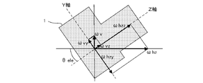
- FIG. 2 is a diagram showing the effect of rotation at a position on the earth.
- the rotation axis (earth's axis) of rotation has an inclination of ⁇ lat degree with respect to the horizontal. Therefore, the rotation vector ( ⁇ rot ) of rotation can be decomposed into the rotation vector ( ⁇ h ) on the horizontal axis and the rotation vector ( ⁇ v ) on the vertical axis as shown in the following equations (1) and (2). it can.
- ⁇ v ⁇ rot ⁇ SIN ⁇ lat equation (1)
- ⁇ h ⁇ rot ⁇ COS ⁇ lat equation (2)
- FIG. 3 is a diagram showing the effect of rotation depending on the orientation of the optical axis of the camera 1 in the normal posture.
- the above-mentioned rotation vector ( ⁇ h ) is further rotated around the Z axis of the camera 1 as shown in the following equations (3) and (4). It can be decomposed into a vector ( ⁇ hz ) and a rotation vector around the X axis ( ⁇ hx).
- FIG. 4 is a diagram further showing the influence of rotation depending on the posture (elevation angle) of the camera 1.
- the camera 1 A rotation vector around the Z axis ( ⁇ z ) and a rotation vector around the Y axis ( ⁇ y' ) are obtained.
- FIG. 5 is a diagram further showing the effect of rotation depending on the posture (tilt around the optical axis) of the camera 1.
- the rotation vector ( ⁇ hx ) and the rotation vector ( ⁇ y' ) described above are shown in the following equations (7) and (8).
- the rotation vector ( ⁇ x ) around the X axis and the rotation vector ( ⁇ y ) around the Y axis of the camera 1 are obtained.
- ⁇ x ⁇ rot ⁇ COS ⁇ lat ⁇ SIN ⁇ direction ⁇ COS ⁇ slope - ( ⁇ rot ⁇ SIN ⁇ lat ⁇ COS ⁇ ele - ⁇ rot ⁇ COS ⁇ lat ⁇ COS ⁇ direction ⁇ SIN ⁇ ele) ⁇ SIN ⁇ slope formula (9)
- ⁇ y ⁇ rot ⁇ COS ⁇ lat ⁇ SIN ⁇ direction ⁇ SIN ⁇ slope + ( ⁇ rot ⁇ SIN ⁇ lat ⁇ COS ⁇ ele ⁇ rot ⁇ COS ⁇ lat ⁇ COS ⁇ direction ⁇ SIN ⁇ ele ) ⁇ COS ⁇ slope equation (10)
- ⁇ z ⁇ rot ⁇ COS ⁇ lat ⁇ COS ⁇ direction ⁇ COS ⁇ ele + ⁇ rot ⁇ SIN ⁇ lat ⁇ SIN ⁇ ele Equation (11)
- the effect of the rotation of the earth on each axis of the camera 1 changes depending on the latitude, attitude (elevation angle, inclination around the optical axis) of the camera 1, and the direction in which it is facing.
- the direction in which the camera 1 is facing is also the shooting direction, the imaging direction, and the direction of the optical axis of the camera 1.
- the reference value of the angular velocity sensor provided in the camera 1 (the output value of the angular velocity sensor when not rotating) is obtained on the earth, the reference value including the influence of rotation is obtained.
- This reference value will be referred to as the rest reference below.
- the output value of the angular velocity sensor at rest excluding the influence of rotation, will be referred to as the sensor reference value below.
- the angular velocity (rotational velocity) including the rotation can be obtained.
- the image stabilization mechanism By performing image stabilization with the image stabilization mechanism based on this angular velocity, it becomes possible to photograph nebulae and stars, which are extraterrestrial subjects, without being affected by diurnal motion.
- FIG. 6 is a block diagram showing a configuration of a camera which is an imaging device according to the first embodiment.
- the camera 1 includes an optical system 2, an image sensor 3, a drive unit 4, a system controller 5, a blur correction microcomputer 6, an angular velocity sensor 7, an acceleration sensor 8, an orientation sensor 9, a position sensor 10, and an EVF ( Electronic View Finder) 11 and operation switch unit (operation SW unit) 12 are included.
- EVF Electronic View Finder
- the optical system 2 forms an image on the image pickup surface of the image pickup device 3 using the luminous flux from the subject as a subject image.
- the optical system 2 is composed of, for example, a plurality of lenses including a focus lens and a zoom lens. In this case, the movement of the focus lens or the like is performed by driving a lens driving mechanism (not shown) under the control of the system controller 5.
- the image sensor 3 converts the subject image imaged on the image pickup surface by the optical system 2 into an electric signal that becomes a pixel signal.
- the image sensor 3 is, for example, an image sensor such as a CCD (charge coupled device) or a CMOS (complementary metal oxide semiconductor).
- the drive unit 4 is a drive mechanism that moves the image sensor 3 in a direction parallel to the image pickup surface (which is also a direction perpendicular to the optical axis of the optical system 2), and moves the image sensor 3 in translation or rotation. It is possible to do it.
- the drive unit 4 includes a plurality of actuators for moving the image pickup device 3.
- the plurality of actuators are, for example, VCM (Voice Coil Motor).
- the system controller 5 reads out the electric signal converted by the image sensor 3 as image data, and performs various image processing on the read image data. Further, the image processed image data is displayed on the EVF 11 or recorded in a memory (for example, a removable recording medium such as a memory card) (not shown). Further, the system controller 5 controls the entire camera including reading the detection result from the directional sensor 9 and the position sensor 10 and data communication with the blur correction microcomputer 6.
- the angular velocity sensor 7 detects the angular velocities of the camera 1 in the Pitch direction, the Yaw direction, and the Roll direction (rotational motion applied to the X-axis, Y-axis, and Z-axis of the camera 1).
- the acceleration sensor 8 detects accelerations that occur in the X, Y, and Z directions of the camera 1 (acceleration applied in parallel to the X, Y, and Z axes of the camera 1).
- the blur correction microcomputer 6 calculates the amount of image movement generated on the image pickup surface of the image pickup element 3 based on the detection result of the angular velocity sensor 7, and moves the image pickup element 3 in a direction that cancels the image movement corresponding to the image movement amount. Controls the drive unit 4. The blur correction microcomputer 6 also determines the posture of the camera 1 based on the detection result of the acceleration sensor 8.
- the azimuth sensor 9 detects the azimuth (azimuth) of the shooting direction (imaging direction) of the camera 1.
- the azimuth sensor 9 is, for example, a geomagnetic sensor.
- the position sensor 10 detects the position of the camera 1 (including at least the latitude).
- the position sensor 10 is, for example, a GPS (Global Positioning System) sensor.
- the GPS sensor detects the position (latitude, longitude, etc.) by receiving radio waves from a plurality of satellites.
- the EVF 11 displays an image according to the image data, a menu screen that enables various settings for the camera 1 by the user, and the like.
- the operation switch unit 12 includes various switches such as a switch for performing a release operation which is a shooting start instruction and a switch for performing an operation according to the menu screen displayed on the EVF 11.
- the switch included in the operation switch unit 12 the user can, for example, set the shooting mode to the normal shooting mode (hereinafter referred to as "normal mode") or enable the astronomical shooting mode (hereinafter referred to as "normal mode"). It can be set to (hereinafter referred to as "celestial body mode").
- the shooting mode is an example of an operation mode
- the normal mode is an example of the first mode
- the celestial body mode is an example of the second mode.
- the operation switch unit 12 may include a mode dial capable of switching the shooting mode to the normal mode or the celestial body mode.
- the system controller 5 and the blur correction microcomputer 6 may be configured by, for example, a dedicated circuit such as an ASIC (Application Specific Integrated Circuit) or an FPGA (Field-Programmable Gate Array).
- a dedicated circuit such as an ASIC (Application Specific Integrated Circuit) or an FPGA (Field-Programmable Gate Array).
- the system controller 5 and the blur correction microcomputer 6 include a processor such as a CPU and a memory, and the processor executes a program recorded in the memory, the functions of the system controller 5 and the blur correction microcomputer 6 are realized. Good.
- FIG. 7 is a block diagram showing a functional configuration of the blur correction microcomputer 6.
- the blur correction microcomputer 6 includes SIO (Serial Input / Output) 601, communication unit 602, reference value subtraction unit 603, correction amount calculation unit 604, drive control unit 605, SIO606, and posture determination unit 607. It includes a sensor reference value calculation unit 608, a stationary reference value holding unit 609, a sensor reference value holding unit 610, and a switching unit 611.
- the SIO601 is a digital serial interface, and reads out the detection results of the angular velocities in the Pitch direction, the Yaw direction, and the Roll direction from the angular velocity sensor 7 at a constant cycle.
- the communication unit 602 communicates with the system controller 5 to acquire information such as the focal length 602a, the azimuth (azimuth) 602b which is the detection result of the azimuth sensor 9, and the latitude 602c which is the detection result of the position sensor 10. Receive instructions such as the start and end of image stabilization.
- the instructions for starting and ending the image stabilization are also instructions for starting and ending the operation of the image stabilization microcomputer 6.
- the reference value subtracting unit 603 sets the reference value at rest from the angular velocity read out by the SIO 601 for each rotation direction in the Pitch direction, the Yaw direction, and the Roll direction.
- the resting reference value held by the holding unit 609 is subtracted to remove the offset noise.
- the stationary reference value holding unit 609 uses the angular velocities in the Pitch direction, the Yaw direction, and the Roll direction, which are the detection results of the angular velocity sensor 7 when the camera 1 is in a stationary state (specifically, in a stationary state with respect to the ground). It is a memory that holds a certain resting reference value, and the resting reference value is a value including an angular velocity component due to rotation.
- the reference value subtracting unit 603 will be described later from the angular velocity read out by the SIO 601 for each rotation direction in the Pitch direction, the Yaw direction, and the Roll direction when the celestial body mode is set as the shooting mode.
- the sensor reference value held in the sensor reference value holding unit 610 is subtracted.
- the correction amount calculation unit 604 calculates the image movement amount on the imaging surface based on the angular velocities in the Pitch direction, the Yaw direction, and the Roll direction, which are the subtraction results of the reference value subtraction unit 603, and the image movement by the image movement amount. Calculate the correction amount (image blur correction amount) for canceling. Specifically, the angular velocity in the Pitch direction, which is the subtraction result of the reference value subtraction unit 603, is multiplied by the focal length 602a to calculate the image movement velocity on the imaging surface, and the image movement in the Y-axis direction is integrated by time integration. The amount is calculated, and the correction amount for canceling the image movement corresponding to the image movement amount is calculated.
- the angular velocity in the Yaw direction which is the subtraction result of the reference value subtraction unit 603, is similarly multiplied by the focal length 602a to calculate the image movement velocity on the imaging surface, and the image in the X-axis direction is integrated over time.
- the movement amount is calculated, and the correction amount for canceling the image movement corresponding to the image movement amount is calculated.
- the angular velocity in the Roll direction which is the subtraction result of the reference value subtraction unit 603, is time-integrated without multiplying the focal length 602a to calculate the image rotation movement amount (rotational movement amount of the subject image). Then, the correction amount for canceling the image rotation movement corresponding to the image rotation movement amount is calculated.
- the reason why the focal length 602a is not multiplied is that the image rotation movement amount obtained by time-integrating the angular velocity in the Roll direction becomes the rotation movement amount of the subject image around the optical axis.
- the drive control unit 605 controls the drive of the drive unit 4 based on the correction amount which is the calculation result of the correction amount calculation unit 604 to move the image sensor 3. Thereby, for example, it is possible to prevent the occurrence of blurring that may occur in the captured image due to handheld shooting in the normal mode.
- the switching unit 611 switches the input and outputs it according to the set shooting mode. Specifically, when the normal mode is set, the stationary reference value held in the stationary reference value holding unit 609 is input, and when the celestial body mode is set, it is held in the sensor reference value holding unit 610. The sensor reference value is input and output.
- the SIO606 is a digital serial interface, and reads out the acceleration applied in the directions of the three axes of the X-axis, the Y-axis, and the Z-axis, which are the detection results, from the acceleration sensor 8. It should be noted that this acceleration includes a gravity component.
- the posture determination unit 607 detects the direction of gravity from the acceleration applied in the directions of the three axes read out by the SIO 606, and determines the attitude of the camera 1.
- the postures determined here are at least the elevation angle of the camera 1 ( see ⁇ ele in FIG. 4) and the inclination around the optical axis ( see ⁇ slope in FIG. 5).
- the sensor reference value calculation unit 608 uses the above equations (9), (10), and (11) to determine the posture (elevation angle, tilt around the optical axis) of the camera 1 determined by the posture determination unit 607. From the azimuth 602b and the latitude 602c, the rotation angular velocities in the Pitch direction, the Yaw direction, and the Roll direction generated in the camera 1 due to the rotation are calculated. Then, the sensor reference value is calculated by subtracting the calculated rotation angular velocity from the stationary reference value held in the stationary reference value holding unit 609 for each rotation direction in the Pitch direction, Yaw direction, and Roll direction. ..
- the sensor reference value holding unit 610 is a memory that holds the sensor reference values in the Pitch direction, the Yaw direction, and the Roll direction, which are the calculation results of the sensor reference value calculation unit 608.
- FIG. 8 is a flowchart showing the flow of the sensor reference value calculation process performed by the blur correction microcomputer 6.
- the attitude determination unit 607 first detects the direction of gravity from the acceleration applied in the directions of the three axes of the X-axis, the Y-axis, and the Z-axis acquired from the acceleration sensor 8.
- the posture (elevation angle, inclination around the optical axis) of the camera 1 is determined based on the direction of gravity (S11).
- the sensor reference value calculation unit 608 uses the above equations (9), (10), and (11) to determine the attitude (elevation angle, tilt around the optical axis) of the camera 1 determined by the attitude determination unit 607. ), The orientation 602b, and the latitude 602c, the rotation angular velocities in the Pitch direction, the Yaw direction, and the Roll direction generated in the camera 1 due to the rotation are calculated (S12).
- the elevation angle, the inclination around the optical axis, the orientation 602b, and the latitude 602c of the camera 1 correspond to ⁇ ele , ⁇ slope , ⁇ direction , and ⁇ lat , and the Pitch direction, the Yaw direction, and the Yaw direction that occur in the camera 1 due to the rotation.
- the rotation angular velocity in the Roll direction corresponds to ⁇ x , ⁇ y , and ⁇ z.
- the sensor reference value calculation unit 608 holds the rotation angular velocity (rotation component) calculated in S12 for each rotation direction in the Pitch direction, Yaw direction, and Roll direction in the stationary reference value holding unit 609. Subtracting from the stationary reference value (S13), the process ends. According to this, the sensor reference values in the Pitch direction, the Yaw direction, and the Roll direction are calculated and held by the sensor reference value holding unit 610.
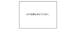
- the calculation process of such a sensor reference value is first performed as a calibration process when the celestial body mode is set as the shooting mode. Since the calibration process needs to be performed with the camera 1 stationary, a notification may be given to the user to urge the camera 1 to be stationary prior to this process. This notification may be made, for example, by display or voice. When this notification is performed by display, for example, the screen shown in FIG. 9 may be displayed on the EVF 11. Alternatively, when this notification is performed by voice, the camera 1 may further include a voice output device including a speaker or the like, and the voice output device may be made to perform the notification by voice. In this case, the EVF 11 and the voice output device are examples of the notification device that notifies the user.
- the image blur correction is performed as the shaking of the camera 1 including the influence of the rotation, so that the astronomical image is taken by holding the camera 1 by hand. Even if it does, astronomical photography that follows the diurnal motion becomes possible, and the stars will not flow and be photographed. Further, as compared with the conventional technique, complicated calculation for astronomical photography is not required, and astronomical follow-up photography can be performed even in the vicinity of the zenith without deteriorating the accuracy.
- the camera 1 may acquire the latitude from an external device.
- the camera 1 may communicate with a mobile information terminal such as a smartphone owned by the user and acquire the latitude detected by the position sensor (for example, GPS sensor) included in the mobile information terminal as the latitude of the camera 1.
- the position sensor for example, GPS sensor
- the camera 1 does not need to include the position sensor 10.
- FIG. 10 is a block diagram showing a configuration of a camera which is an imaging device according to a second embodiment. Since the camera 1 according to the second embodiment does not calculate the sensor reference value, information on the posture (elevation angle, inclination around the optical axis), orientation, and latitude of the camera 1 is unnecessary. Therefore, the camera 1 according to the second embodiment does not include the acceleration sensor 8, the direction sensor 9, and the position sensor 10 as shown in FIG. Instead, it includes a temperature control unit 13 and a temperature sensor 14.
- the temperature control unit 13 is a device that heats or cools the angular velocity sensor 7, and is, for example, a Peltier element.
- the Peltier element is a device that can freely heat and cool depending on the direction in which an electric current flows.
- the temperature sensor 14 detects the temperature of the angular velocity sensor 7 (specifically, the sensor element of the angular velocity sensor 7). It is desirable that the temperature sensor 14 is integrally formed with the angular velocity sensor 7 in order to detect the temperature more accurately.
- the blur correction microcomputer 6 when the celestial body mode is set and the temperature of the angular velocity sensor 7 is further acquired by the sensor reference value held by the sensor reference value holding unit 610.
- the temperature control unit 13 is controlled based on the detection result of the temperature sensor 14 in order to maintain the temperature of the angular velocity sensor 7.
- the sensor reference value acquired in the adjustment process at the time of manufacturing the camera 1 and the temperature of the angular velocity sensor 7 at the time of acquisition are held in the sensor reference value holding unit 610.
- the sensor reference value is obtained from the angular velocity detected by the angular velocity sensor 7 when the camera 1 is in a stationary state in each rotation direction of the camera 1, for example, the Pitch direction, the Yaw direction, and the Roll direction in the adjustment step. , Obtained by removing the rotation angular velocity component generated in the camera 1 due to rotation.
- the rotation angular velocity component may be calculated using the above equations (9), (10), and (11), for example, as in the first embodiment.
- FIG. 11 is a block diagram showing a functional configuration of the blur correction microcomputer 6 according to the second embodiment.
- the difference from the first embodiment is that instead of having a configuration related to the calculation of the sensor reference value, a temperature acquisition unit 612 and a temperature control unit 613 are provided, and the SIO601 is further provided with a temperature sensor. This is a point at which the detected value is read from 14.
- the temperature acquisition unit 612 converts the detected value read from the temperature sensor 14 by the SIO 601 into a temperature (temperature value).
- the temperature control unit 613 is the temperature converted by the temperature acquisition unit 612 in order to maintain the temperature of the angular velocity sensor 7 at the temperature of the angular velocity sensor 7 at the time of acquiring the sensor reference value, which is held by the sensor reference value holding unit 610.
- the temperature control unit 13 is controlled based on the value.
- the temperature (temperature value) converted by the temperature acquisition unit 612 is compared with the temperature of the angular velocity sensor 7 held in the sensor reference value holding unit 610 at the time of sensor reference value acquisition, and the former
- the temperature control unit 13 is controlled to heat the angular velocity sensor 7, and conversely, when the temperature is higher, the temperature control section 13 is controlled to cool the angular velocity sensor 7.
- the control of the temperature control unit 13 may be stopped.
- the temperature of the angular velocity sensor 7 constant (the temperature at the time of acquiring the sensor reference value)
- the temperature drift of the angular velocity sensor 7 can be suppressed. It is possible to detect the rotation angular velocity generated in the camera 1 by the rotation with high accuracy. Further, in the present embodiment, it is not necessary to provide a configuration related to the calculation of the sensor reference value such as the acceleration sensor 8, the direction sensor 9, the position sensor 10, and the like, so that the product cost of the camera 1 can be suppressed.
- FIG. 12 is a block diagram showing a configuration of a camera which is an imaging device according to a third embodiment.
- the difference from the first embodiment is that the acceleration sensor 8, the directional sensor 9, and the position sensor 10 are not provided.
- the camera 1 according to the third embodiment has a calibration mode as an operation mode, and when the calibration mode is set, the influence of rotation while prompting the user to sequentially switch the posture of the camera 1.
- the reference value in the rotation direction that is not affected by the sensor is sequentially acquired as the sensor reference value. According to this, the sensor reference value of each rotation direction of the Pitch direction, the Yaw direction, and the Roll direction is acquired.
- FIG. 13 is a block diagram showing a functional configuration of the blur correction microcomputer 6 according to the third embodiment. As shown in FIG. 13, the difference from the first embodiment is that the configuration related to the calculation of the sensor reference value is not provided. Instead, in the third embodiment, the resting reference value acquired when the calibration mode is set is held as it is in the sensor reference value holding unit 610 as the sensor reference value.
- FIG. 14 is a flowchart showing the flow of the calibration process.
- FIG. 15 is an example of a screen displayed on the EVF 11 during execution of the calibration process.
- the calibration process starts when the calibration mode is set.
- the calibration mode is set, for example, according to the operation of the operation switch unit 12 by the user.
- the camera 1 first displays the screen 11a shown in FIG. 15 on the EVF 11 and prompts the user to stop the camera 1 in the north-facing positive posture (S21).
- the influence of rotation does not occur in the Pitch direction of the camera 1.
- the camera 1 detects the switch operation and then operates.
- the angular velocity in the Pitch direction detected by the angular velocity sensor 7 is acquired and held in the sensor reference value holding unit 610 as the sensor reference value in the Pitch direction (S22).
- the camera 1 displays the screen 11b shown in FIG. 15 on the EVF 11 and prompts the user to stop the camera 1 in a vertical posture facing north (S23).
- the vertical posture is a posture in which the X-axis of the camera 1 is perpendicular to the horizontal plane.
- the camera 1 detects the switch operation and then the Yaw direction detected by the angular velocity sensor 7.
- the angular velocity of is acquired and held in the sensor reference value holding unit 610 as the sensor reference value in the Yaw direction (S24).
- the influence of rotation does not occur in the Yaw direction of the camera 1.
- the camera 1 displays the screen 11c shown in FIG. 15 on the EVF 11 and prompts the user to stop the camera 1 in a positive posture facing east (S25).
- a positive posture facing east S25.
- the camera 1 detects the switch operation and then the Roll direction detected by the angular velocity sensor 7.
- the angular velocity of the above is acquired and held in the sensor reference value holding unit 610 as the sensor reference value in the Roll direction (S26), and the process is completed.
- the sensor reference values in the Pitch direction, the Yaw direction, and the Roll direction are held by the sensor reference value holding unit 610.
- the sensor reference value holding unit 610 can hold the sensor reference value corresponding to the aged deterioration of the angular velocity sensor 7.
- the camera 1 may be provided with the acceleration sensor 8 and the direction sensor 9, and it may be automatically determined that the camera 1 is in the posture according to the display screen in the above calibration process.
- the above-mentioned calibration process may be performed first each time the celestial body mode is set. Further, when the calibration process is completed, the calibration mode may be automatically switched to another mode (for example, an astronomical mode).
- the user is notified to urge the posture of the camera 1 by the display of the EVF 11, but the present invention is not limited to this.
- the camera 1 further includes an audio output device including a speaker and the like, and depends on the voice. A notification prompting the posture of the camera 1 may be given.
- the EVF 11 and the voice output device are examples of the notification device that notifies the user.
- FIG. 16 is a block diagram showing a functional configuration of the blur correction microcomputer 6 according to a modified example of the third embodiment.
- the blur correction microcomputer 6 further includes a switching unit 616, a tripod determination unit 617, and an LPF (Low Pass Filter) 618.
- the tripod determination unit 617 determines whether or not the camera 1 is installed on the tripod based on the amplitude of the angular velocity which is the subtraction result of the reference value subtraction unit 603. Specifically, when the amplitude of the angular velocity is equal to or less than a predetermined amplitude, it is determined that the state is installed on a tripod, and when not, it is determined that the state is not installed on a tripod.
- the determination made by the tripod determination unit 617 is also to determine whether or not the camera 1 is fixed.
- the LPF618 performs LPF processing on the angular velocities in the Pitch direction, the Yaw direction, and the Roll direction, which are the subtraction results of the reference value subtracting unit 603. This makes it possible to block high frequency noise components.
- the LPF618 is an example of a filter circuit that performs a filter process for blocking high frequency components.
- the switching unit 616 switches the input and outputs it according to the determination result of the tripod determination unit 617. Specifically, when the tripod determination unit 617 determines that the camera 1 is installed on a tripod, the processing result of LPF618 is input, and the tripod determination unit 617 is not installed on the tripod. If the determination is made according to the above, the subtraction result of the reference value subtraction unit 603 is input and output.
- the reason for switching such inputs is that when the camera 1 is installed on a tripod (that is, fixed), the angular velocity generated in the camera 1 is only the angular velocity due to the rotation (rotation angular velocity), and this rotation angular velocity. In this case, LPF processing is performed to prevent image blur correction whose accuracy is lowered due to the influence of random noise such as readout noise.
- FIG. 17 is a block diagram showing a functional configuration of the blur correction microcomputer 6 according to the fourth embodiment.
- the difference from the third embodiment is that it further includes a switching unit 616, a rotation calculation unit 619, and an amplitude determination unit 620.
- the switching unit 616 switches the input and outputs it according to the set shooting mode. Specifically, when the normal mode is set, the subtraction result of the reference value subtraction unit 603 is input, and when the celestial body mode is set, the calculation result of the rotation calculation unit 619 (held by the rotation calculation unit 619). The calculation result) is input and output.
- the rotation calculation unit 619 depends on the reference value subtraction unit 603 for each rotation direction in the Pitch direction, Yaw direction, and Roll direction during a predetermined period (for example, 1 second or more) and determines the sensor reference value. Calculates and holds the average value of the angular velocity subtracted by.
- the angular velocity at which the sensor reference value is subtracted by the reference value subtracting unit 603 is only the rotation angular velocity generated by the camera 1 due to the rotation. Then, by obtaining the average value of the angular velocities from which the sensor reference value is subtracted by the reference value subtracting unit 603 during a predetermined time, the angular velocity sensor 7 has a small S / N (Signal / Noise) ratio (that is, noise is generated). Even with a sensor (many), it is possible to obtain a value with little error. In particular, by lengthening the predetermined time, a value with less error can be obtained.
- the amplitude determination unit 620 determines whether or not the amplitude of the angular velocity, which is the detection result of the angular velocity sensor 7, is equal to or less than a predetermined amplitude.
- the determination result of the amplitude determination unit 620 is notified to the system controller 5 by the communication unit 602.
- the determination result of the amplitude determination unit 620 is used when determining whether or not the vibration generated in the camera 1 is settled by the user's release operation at the start of shooting.
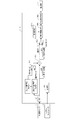
- FIG. 18 is a flowchart showing the flow of control processing related to photographing performed by the system controller 5 according to the fourth embodiment.
- This control process is started by issuing a shooting start instruction by the user's release operation on the operation switch unit 12.
- a shooting start instruction by the user's release operation on the operation switch unit 12.
- an instruction to start shooting a still image is given.
- the celestial body mode is set as the shooting mode.
- the system controller 5 first inquires of the blur correction microcomputer 6 whether or not the vibration accompanying the release operation has converged, and waits until the vibration converges (S31). Since vibration does not occur when the release operation is performed remotely, the process of S31 may be omitted.
- the amplitude determination unit 620 determines whether or not the angular velocity, which is the detection result of the angular velocity sensor 7, is equal to or less than a predetermined amplitude. Then, when the blur correction microcomputer 6 notifies the determination result by the amplitude determination unit 620 that the amplitude is equal to or less than a predetermined amplitude, the system controller 5 instructs the blur correction microcomputer 6 to calculate the rotation speed (S32).
- the rotation calculation unit 619 calculates and holds the average value of the angular velocities obtained by subtracting the sensor reference value by the reference value subtraction unit 603 during a predetermined period in response to the instruction.
- the system controller 5 instructs the blur correction microcomputer 6 to start the rotation correction (S33).
- the switching unit 616 performs input switching using the input as the calculation result of the rotation calculation unit 619 (calculation result held in the rotation calculation unit 619). Then, the correction amount calculation unit 604 calculates the correction amount in the same manner from the average value of the rotation angular velocities calculated and held by the rotation calculation unit 619 for each rotation direction in the Pitch direction, the Yaw direction, and the Roll direction.
- the blur correction microcomputer 6 starts image blur correction related to rotation, such as the drive control unit 605 driving the drive unit 4 based on the correction amount.
- the system controller 5 exposes the still image (S34), and when the exposure is completed, reads out the electric signal converted by the image sensor 3 as image data to acquire the captured image (S35), and corrects the blur.
- the microcomputer 6 is instructed to end the rotation correction (S36), and the process ends.
- FIG. 19 is a timing chart showing an operation example of the image sensor 3, the blur correction microcomputer 6, and the drive unit 4 according to the fourth embodiment.
- the image sensor 3 is exposed for live view during the shooting standby (for example, before the shooting start instruction).
- the image stabilization microcomputer 6 performs an image stabilization operation such as calculating a correction amount suitable for live view and controlling the drive of the drive unit 4.
- the correction position is moved by a camera shake correction operation suitable for live view.
- FIG. 19 shows a change in the correction position of the drive unit 4 as an operation of the drive unit 4.
- the image sensor 3 is shielded from light by the front curtain of a shutter (not shown). At this time, the dark current of the image sensor 3 may be acquired, and the dark current portion may be subtracted later. Further, when the configuration does not include the front curtain, the image sensor 3 may be maintained in the reset state.
- the image sensor 3 starts the still image exposure.
- the blur correction microcomputer 6 calculates the correction amount (rotation correction amount) from the average value (rotation angular velocity) calculated by the rotation calculation unit 619 by the integration or the like by the correction amount calculation unit 604.
- the correction position moves at a constant speed based on the rotation correction amount, and the movement of the celestial body imaged on the image sensor 3 due to the diurnal motion is canceled out, and the image sensor 3 The image pickup position of the subject image is maintained.
- the image sensor 3 is shielded from light by the rear curtain of a shutter (not shown), and the image data is read out from the image sensor 3.
- the blur correction microcomputer 6 the correction amount is cleared, and the correction position of the drive unit 4 moves to the initial position.
- the rotation calculation unit 619 may be performed while waiting for shooting.
- FIG. 20 is a block diagram showing a functional configuration of the blur correction microcomputer 6 according to the fifth embodiment.
- the difference from the first embodiment is that the rotation angular velocity calculation unit 621 is provided instead of the sensor reference value calculation unit 608 and the sensor reference value holding unit 610.
- the rotation angular velocity calculation unit 621 uses the above equations (9), (10), and (11) to determine the posture (elevation angle, tilt around the optical axis) and orientation of the camera 1 determined by the posture determination unit 607. From 602b and the latitude 602c, the rotation angular velocities in the Pitch direction, the Yaw direction, and the Roll direction generated in the camera 1 due to the rotation are calculated.
- the rotation angular velocity calculation unit 621 includes a memory that holds the calculated rotation angular velocity in each rotation direction.
- the reference value subtracting unit 603 is held by the stationary reference value holding unit 609 from the angular velocity read out by the SIO 601 in each rotation direction of the Pitch direction, the Yaw direction, and the Roll direction. Subtract the reference value at rest.
- the switching unit 611 switches the input and outputs it according to the set shooting mode. Specifically, when the normal mode is set, the subtraction result of the reference value subtraction unit 603 is input, and when the celestial body mode is set, the calculation result of the rotation angular velocity calculation unit 621 is input and output. According to this, when the celestial body mode is set, the image blur correction is performed based on the rotation angular velocity generated in the camera 1 due to the rotation.
- the angular velocity sensor 7 does not have the sensitivity to detect the rotation angular velocity, it is possible to perform imaging following the celestial body.
- the calculation load is smaller than that of the conventional technique, and astronomical tracking photography can be performed even near the zenith without deteriorating the accuracy.
- a sixth embodiment is a camera system including an information processing terminal such as a smartphone or tablet and a camera, and a user can perform astronomical photography by operating the camera using the information processing terminal.
- the information processing terminal is specified from the coordinates of the specified celestial body, the current date and time, and the latitude of the current position of the information processing terminal.
- the direction and altitude (elevation angle) of the celestial body are calculated, and the rotation angle speeds of the Pitch direction, the Yaw direction, and the Roll direction generated in the camera due to the rotation are calculated.
- the information processing terminal notifies the camera installed on the tripod or the like of the calculated rotation angular velocity in each rotation direction, and the camera performs image blur correction based on the notified rotation angular velocity in each rotation direction. This makes it possible to take pictures that follow the celestial body.
- FIG. 21 is a block diagram showing a configuration of a camera which is an imaging device according to a sixth embodiment.
- the same components as those of the other embodiments are designated by the same reference numerals, and the description thereof will be omitted.
- the camera 1 includes an optical system 2, an image sensor 3, a drive unit 4, a system controller 5, a blur correction microcomputer 6, an angular velocity sensor 7, an acceleration sensor 8, and external communication. Including part 15.
- the external communication unit 15 is a communication interface that performs wireless communication with an external device such as an information processing terminal by using Wifi (registered trademark), Bluetooth (registered trademark), or the like.
- the external communication unit 15 receives various instructions such as a shooting instruction from the information processing terminal, and transmits a shot image or a shot video to the information processing terminal.
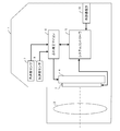
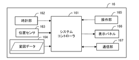
- FIG. 22 is a block diagram showing a configuration of an information processing terminal.
- the information processing terminal 16 includes a system controller 161, a clock unit 162, a position sensor 163, a star map data holding unit 164, an operation unit 165, a display panel 166, and a communication unit 167.
- the system controller 161 controls the entire information processing terminal 16.
- the clock unit 162 has a calendar function and a clock function, and acquires the current date and time.
- the clock unit 162 is an example of a date / time acquisition circuit for acquiring the current date / time.
- the position sensor 163 detects the current position (including at least latitude) of the information processing terminal 16.
- the position sensor 163 is, for example, a GPS sensor.
- the star map data holding unit 164 is a memory for holding star map data in the equatorial coordinate system.
- the operation unit 165 accepts operations for giving various instructions such as instructions to the camera 1.
- the operation unit 165 is a touch panel provided on the front surface of the display panel 166.
- the display panel 166 displays an operation screen of the camera 1 and a star map according to the star map data.
- the display panel is, for example, an LCD (liquid crystal display).
- the communication unit 167 is a communication interface that performs wireless communication between external devices such as the camera 1 by Wifi (registered trademark), Bluetooth (registered trademark), or the like. For example, the communication unit 167 transmits various instructions such as a shooting instruction to the camera 1 and receives a shot image or a shot video from the camera 1.
- the system controller 161 may be configured by, for example, a dedicated circuit such as an ASIC or an FPGA.
- the system controller 161 may include, for example, a processor such as a CPU and a memory, and the function of the system controller 161 may be realized by the processor executing a program recorded in the memory.
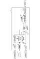
- FIG. 23 is a flowchart showing the flow of control processing related to photographing performed by the system controller 161 of the information processing terminal 16. This process is performed when a shooting instruction is given to the camera 1 from the information processing terminal 16.
- the system controller 161 is first held in the star map data holding unit 164 based on the date and time acquired by the clock unit 162 and the latitude detected by the position sensor 163.
- the star map data of the equatorial coordinate system is converted into the star map data of the horizontal coordinate system (S41).
- the system controller 161 determines as a display area a partial star map including at least a part on the horizon in the star map corresponding to the star map data of the horizontal coordinate system, and displays the determined partial star map as the display area on the display panel 166. (S42).
- the touch position is provided on the front surface of the display panel 166. It is detected by the touch panel (operation unit) 165 and notified to the system controller 161.
- the system controller 161 acquires the horizontal coordinates of the celestial body to be photographed from the partial star map of the horizontal coordinate system displayed on the display panel 166 and the coordinates of the touch position notified from the touch panel (operation unit) 165 (S44). ).
- the system controller 161 acquires the direction and altitude (elevation angle) of the celestial body to be photographed from the acquired horizontal coordinates (S45).
- the system controller 161 calculates the effect of rotation based on the acquired azimuth and altitude (elevation angle) and the latitude detected by the position sensor 163 (S46).
- the effect of rotation is the rotation angular velocity in each rotation direction of the camera 1 in the Pitch direction, Yaw direction, and Roll direction, and the above equations (9), (10), and (11) are used. Can be calculated.
- the ⁇ slope may be set to 0 and the rotation angular velocity may be calculated.
- the system controller 161 notifies the camera 1 of the shooting start instruction together with the calculated effect of the rotation (S47).
- the system controller 161 determines whether or not the exposure time has elapsed (S48), and waits until the exposure time elapses.
- the shooting is bulb shooting, it is determined whether or not the operation of the shooting end instruction by the user has been accepted, and the process waits until the operation is accepted.
- the system controller 161 notifies the camera 1 of the shooting end instruction (S49), and the process ends.
- FIG. 24 is a block diagram showing a functional configuration of the blur correction microcomputer 6 according to the sixth embodiment.
- the blur correction microcomputer 6 according to the present embodiment holds the rotation angular velocity (effect of the above-mentioned rotation) notified from the information processing terminal 16 instead of calculating the rotation angular velocity inside the camera 1.
- a rotation angular velocity holding unit 622 provided with a memory is provided. According to this, in the celestial body mode, the rotation angular velocity held by the rotation angular velocity holding unit 622 is output to the correction amount calculation unit 604 by the input switching by the switching unit 611.
- the rotation angular velocity holding unit 622 corrects the held rotation angular velocity based on the inclination around the optical axis, if there is an inclination around the optical axis from the attitude determined by the attitude determination unit 607. For example, as described above, even if it is assumed that the shooting is performed in a state where the camera 1 is not tilted around the optical axis, the actual state is such that the camera 1 is not tilted around the optical axis. This is because it may not be.
- the influence of the rotation is calculated by the external information processing terminal 16, it is not necessary to perform complicated calculation in the camera 1. Further, since the celestial body to be photographed is specified from the star map, the direction and elevation angle (altitude) of the celestial body to be photographed can be accurately acquired.
- the inclination around the optical axis of the camera 1 used when the system controller 161 of the information processing terminal 16 calculates the influence of the rotation may be acquired from the camera 1.
- the information processing terminal 16 communicates with the camera 1, and the posture (inclination around the optical axis) of the camera 1 determined by the posture determination unit 607 of the camera 1 is acquired from the camera 1.
- the image blur correction is performed by the drive control unit 605 driving and controlling the drive unit 4 to move the image sensor 3, but the camera 1 is provided with a part of the lenses of the optical system 2.
- a drive mechanism for moving the lens in a direction orthogonal to the optical axis is further provided, and the drive control unit 605 controls the drive mechanism and the drive unit 4 to move a part of the lens and the image sensor 3.
- Image blur correction may be performed depending on the above. In this case, for example, a part of the lenses may be translated and the image sensor 3 may be rotationally moved, or a part of the lenses may be translated and the image sensor 3 may be translated and rotated. ..
- the first or second embodiment may be combined with the third embodiment.
- the control may be performed based on the third embodiment, and if not, the control may be performed based on the first or second embodiment.
- the sensor reference value was acquired in the adjustment step at the time of manufacturing, but the sensor reference value acquired by the method described in the third embodiment and the temperature of the angular velocity sensor 7 at that time are obtained. It may be used while being held by the sensor reference value holding unit at 610.
- the rotation angular velocity which is the output of the communication unit 602 of the sixth embodiment may be input instead of the direction 602b and the latitude 602c. That is, the sensor reference value calculation unit 608 of the first embodiment rotates from the attitude (elevation angle, inclination around the optical axis) of the camera 1 determined by the attitude determination unit 607, the direction 602b, and the latitude 602c. The rotation angular velocity in each rotation direction in the Pitch direction, the Yaw direction, and the Roll direction generated in the camera 1 is calculated according to the above. On the other hand, the sensor reference value calculation unit 608 may use the rotation angular velocity which is the output of the communication unit 602 without calculating the rotation angular velocity.
Landscapes
- Engineering & Computer Science (AREA)
- Multimedia (AREA)
- Signal Processing (AREA)
- Physics & Mathematics (AREA)
- General Physics & Mathematics (AREA)
- Aviation & Aerospace Engineering (AREA)
- Human Computer Interaction (AREA)
- Adjustment Of Camera Lenses (AREA)
- Studio Devices (AREA)
- Indication In Cameras, And Counting Of Exposures (AREA)
Priority Applications (3)
| Application Number | Priority Date | Filing Date | Title |
|---|---|---|---|
| PCT/JP2019/035004 WO2021044585A1 (ja) | 2019-09-05 | 2019-09-05 | 撮像装置、システム、像ぶれ補正方法、プログラム、及び記録媒体 |
| JP2021543894A JP7269354B2 (ja) | 2019-09-05 | 2019-09-05 | 撮像装置、システム、像ぶれ補正方法、プログラム、及び記録媒体 |
| US17/686,136 US20220201211A1 (en) | 2019-09-05 | 2022-03-03 | Image pickup apparatus, system, image stabilization method and recording medium |
Applications Claiming Priority (1)
| Application Number | Priority Date | Filing Date | Title |
|---|---|---|---|
| PCT/JP2019/035004 WO2021044585A1 (ja) | 2019-09-05 | 2019-09-05 | 撮像装置、システム、像ぶれ補正方法、プログラム、及び記録媒体 |
Related Child Applications (1)
| Application Number | Title | Priority Date | Filing Date |
|---|---|---|---|
| US17/686,136 Continuation US20220201211A1 (en) | 2019-09-05 | 2022-03-03 | Image pickup apparatus, system, image stabilization method and recording medium |
Publications (1)
| Publication Number | Publication Date |
|---|---|
| WO2021044585A1 true WO2021044585A1 (ja) | 2021-03-11 |
Family
ID=74852392
Family Applications (1)
| Application Number | Title | Priority Date | Filing Date |
|---|---|---|---|
| PCT/JP2019/035004 Ceased WO2021044585A1 (ja) | 2019-09-05 | 2019-09-05 | 撮像装置、システム、像ぶれ補正方法、プログラム、及び記録媒体 |
Country Status (3)
| Country | Link |
|---|---|
| US (1) | US20220201211A1 (https=) |
| JP (1) | JP7269354B2 (https=) |
| WO (1) | WO2021044585A1 (https=) |
Cited By (1)
| Publication number | Priority date | Publication date | Assignee | Title |
|---|---|---|---|---|
| CN114371738A (zh) * | 2022-01-10 | 2022-04-19 | 刘新阳 | 一种天文望远镜及其校准方法 |
Families Citing this family (1)
| Publication number | Priority date | Publication date | Assignee | Title |
|---|---|---|---|---|
| JP2025033652A (ja) * | 2023-08-30 | 2025-03-13 | キヤノン株式会社 | 画像処理装置、撮像装置、画像処理方法、およびプログラム |
Citations (8)
| Publication number | Priority date | Publication date | Assignee | Title |
|---|---|---|---|---|
| JP2011114357A (ja) * | 2009-11-24 | 2011-06-09 | Panasonic Corp | 撮像装置 |
| JP2012010327A (ja) * | 2010-05-28 | 2012-01-12 | Hoya Corp | 天体自動追尾撮影方法及び天体自動追尾撮影装置 |
| JP2012089960A (ja) * | 2010-10-18 | 2012-05-10 | Canon Inc | 手ぶれ防止機構を備えたカメラ |
| JP2013005244A (ja) * | 2011-06-17 | 2013-01-07 | Pentax Ricoh Imaging Co Ltd | 天体自動追尾撮影方法及び天体自動追尾撮影装置 |
| JP2014209795A (ja) * | 2010-04-28 | 2014-11-06 | リコーイメージング株式会社 | 撮影装置及び撮影方法 |
| JP2015215427A (ja) * | 2014-05-08 | 2015-12-03 | オリンパス株式会社 | 撮像装置及び撮像方法 |
| JP2016005160A (ja) * | 2014-06-18 | 2016-01-12 | キヤノン株式会社 | 撮像装置およびその制御方法 |
| WO2018230316A1 (ja) * | 2017-06-12 | 2018-12-20 | 富士フイルム株式会社 | ブレ検出装置、撮像装置、レンズ装置、撮像装置本体、ブレ検出方法及びブレ検出プログラム |
Family Cites Families (1)
| Publication number | Priority date | Publication date | Assignee | Title |
|---|---|---|---|---|
| JP6091255B2 (ja) * | 2013-02-28 | 2017-03-08 | オリンパス株式会社 | ブレ量検出装置及び撮像装置 |
-
2019
- 2019-09-05 JP JP2021543894A patent/JP7269354B2/ja active Active
- 2019-09-05 WO PCT/JP2019/035004 patent/WO2021044585A1/ja not_active Ceased
-
2022
- 2022-03-03 US US17/686,136 patent/US20220201211A1/en not_active Abandoned
Patent Citations (9)
| Publication number | Priority date | Publication date | Assignee | Title |
|---|---|---|---|---|
| JP2011114357A (ja) * | 2009-11-24 | 2011-06-09 | Panasonic Corp | 撮像装置 |
| JP2014209795A (ja) * | 2010-04-28 | 2014-11-06 | リコーイメージング株式会社 | 撮影装置及び撮影方法 |
| JP2012010327A (ja) * | 2010-05-28 | 2012-01-12 | Hoya Corp | 天体自動追尾撮影方法及び天体自動追尾撮影装置 |
| JP2015181266A (ja) * | 2010-05-28 | 2015-10-15 | リコーイメージング株式会社 | 天体自動追尾撮影方法及び天体自動追尾撮影装置 |
| JP2012089960A (ja) * | 2010-10-18 | 2012-05-10 | Canon Inc | 手ぶれ防止機構を備えたカメラ |
| JP2013005244A (ja) * | 2011-06-17 | 2013-01-07 | Pentax Ricoh Imaging Co Ltd | 天体自動追尾撮影方法及び天体自動追尾撮影装置 |
| JP2015215427A (ja) * | 2014-05-08 | 2015-12-03 | オリンパス株式会社 | 撮像装置及び撮像方法 |
| JP2016005160A (ja) * | 2014-06-18 | 2016-01-12 | キヤノン株式会社 | 撮像装置およびその制御方法 |
| WO2018230316A1 (ja) * | 2017-06-12 | 2018-12-20 | 富士フイルム株式会社 | ブレ検出装置、撮像装置、レンズ装置、撮像装置本体、ブレ検出方法及びブレ検出プログラム |
Cited By (2)
| Publication number | Priority date | Publication date | Assignee | Title |
|---|---|---|---|---|
| CN114371738A (zh) * | 2022-01-10 | 2022-04-19 | 刘新阳 | 一种天文望远镜及其校准方法 |
| CN114371738B (zh) * | 2022-01-10 | 2024-01-19 | 刘新阳 | 一种天文望远镜及其校准方法 |
Also Published As
| Publication number | Publication date |
|---|---|
| JPWO2021044585A1 (https=) | 2021-03-11 |
| US20220201211A1 (en) | 2022-06-23 |
| JP7269354B2 (ja) | 2023-05-08 |
Similar Documents
| Publication | Publication Date | Title |
|---|---|---|
| JP7707386B2 (ja) | 撮影システム | |
| JP7516623B2 (ja) | 天体追尾装置および天体追尾方法 | |
| JP4607048B2 (ja) | 光学モーションセンサをジャイロスコープとして使用する撮像装置 | |
| US8212860B2 (en) | Digital camera having an image mover | |
| CN104067166B (zh) | 抖动量检测装置、摄像装置、抖动量检测方法 | |
| US8844148B2 (en) | Direction determining method and apparatus using a triaxial electronic compass | |
| JP2000010141A (ja) | 手振れ補正機能付きデジタルカメラ | |
| CN103733131B (zh) | 抖动量检测装置、摄像装置和抖动量检测方法 | |
| JP5846927B2 (ja) | ブレ量検出装置、撮像装置、ブレ量検出方法 | |
| US10412306B1 (en) | Optical image stabilization method and apparatus | |
| CN110278354A (zh) | 镜头装置、相机、控制方法及存储介质 | |
| US20220201211A1 (en) | Image pickup apparatus, system, image stabilization method and recording medium | |
| KR20070033272A (ko) | 흐림 현상 감소 시스템을 갖는 촬상 장치 | |
| JP2022003789A (ja) | ブレ検出装置、撮像装置、レンズ装置、撮像装置本体、ブレ検出方法、ブレ検出プログラム及び記録媒体 | |
| JP2011114357A (ja) | 撮像装置 | |
| JP2012089960A (ja) | 手ぶれ防止機構を備えたカメラ | |
| JP7017961B2 (ja) | ぶれ補正装置及びぶれ補正方法 | |
| JP2018197825A (ja) | 制御装置及び方法、及び撮像装置 | |
| JP7563042B2 (ja) | 撮影装置、撮影方法、撮影システム及び電子機器 | |
| JP6402640B2 (ja) | 撮影システム | |
| JP2015049446A (ja) | 撮像装置 | |
| JP2024156226A (ja) | 天体追尾システム及び天体追尾制御プログラム | |
| CN117941367A (zh) | 成像设备、图像处理方法以及程序 | |
| JP2024003461A (ja) | 姿勢算出装置、姿勢算出方法、姿勢算出装置を備える撮像装置とその制御方法 | |
| JP2024003460A (ja) | 姿勢算出装置、姿勢算出方法、姿勢算出装置を備える撮像装置とその制御方法 |
Legal Events
| Date | Code | Title | Description |
|---|---|---|---|
| 121 | Ep: the epo has been informed by wipo that ep was designated in this application |
Ref document number: 19943873 Country of ref document: EP Kind code of ref document: A1 |
|
| ENP | Entry into the national phase |
Ref document number: 2021543894 Country of ref document: JP Kind code of ref document: A |
|
| NENP | Non-entry into the national phase |
Ref country code: DE |
|
| 122 | Ep: pct application non-entry in european phase |
Ref document number: 19943873 Country of ref document: EP Kind code of ref document: A1 |