WO2021044585A1 - Imaging device, system, image blurring correction method, program, and recording medium - Google Patents
Imaging device, system, image blurring correction method, program, and recording medium Download PDFInfo
- Publication number
- WO2021044585A1 WO2021044585A1 PCT/JP2019/035004 JP2019035004W WO2021044585A1 WO 2021044585 A1 WO2021044585 A1 WO 2021044585A1 JP 2019035004 W JP2019035004 W JP 2019035004W WO 2021044585 A1 WO2021044585 A1 WO 2021044585A1
- Authority
- WO
- WIPO (PCT)
- Prior art keywords
- image
- rotation
- angular velocity
- sensor
- image pickup
- Prior art date
Links
Images


Classifications
-
- H—ELECTRICITY
- H04—ELECTRIC COMMUNICATION TECHNIQUE
- H04N—PICTORIAL COMMUNICATION, e.g. TELEVISION
- H04N23/00—Cameras or camera modules comprising electronic image sensors; Control thereof
- H04N23/60—Control of cameras or camera modules
- H04N23/68—Control of cameras or camera modules for stable pick-up of the scene, e.g. compensating for camera body vibrations
- H04N23/681—Motion detection
- H04N23/6812—Motion detection based on additional sensors, e.g. acceleration sensors
-
- G—PHYSICS
- G03—PHOTOGRAPHY; CINEMATOGRAPHY; ANALOGOUS TECHNIQUES USING WAVES OTHER THAN OPTICAL WAVES; ELECTROGRAPHY; HOLOGRAPHY
- G03B—APPARATUS OR ARRANGEMENTS FOR TAKING PHOTOGRAPHS OR FOR PROJECTING OR VIEWING THEM; APPARATUS OR ARRANGEMENTS EMPLOYING ANALOGOUS TECHNIQUES USING WAVES OTHER THAN OPTICAL WAVES; ACCESSORIES THEREFOR
- G03B5/00—Adjustment of optical system relative to image or object surface other than for focusing
-
- G—PHYSICS
- G03—PHOTOGRAPHY; CINEMATOGRAPHY; ANALOGOUS TECHNIQUES USING WAVES OTHER THAN OPTICAL WAVES; ELECTROGRAPHY; HOLOGRAPHY
- G03B—APPARATUS OR ARRANGEMENTS FOR TAKING PHOTOGRAPHS OR FOR PROJECTING OR VIEWING THEM; APPARATUS OR ARRANGEMENTS EMPLOYING ANALOGOUS TECHNIQUES USING WAVES OTHER THAN OPTICAL WAVES; ACCESSORIES THEREFOR
- G03B17/00—Details of cameras or camera bodies; Accessories therefor
- G03B17/55—Details of cameras or camera bodies; Accessories therefor with provision for heating or cooling, e.g. in aircraft
-
- G—PHYSICS
- G03—PHOTOGRAPHY; CINEMATOGRAPHY; ANALOGOUS TECHNIQUES USING WAVES OTHER THAN OPTICAL WAVES; ELECTROGRAPHY; HOLOGRAPHY
- G03B—APPARATUS OR ARRANGEMENTS FOR TAKING PHOTOGRAPHS OR FOR PROJECTING OR VIEWING THEM; APPARATUS OR ARRANGEMENTS EMPLOYING ANALOGOUS TECHNIQUES USING WAVES OTHER THAN OPTICAL WAVES; ACCESSORIES THEREFOR
- G03B3/00—Focusing arrangements of general interest for cameras, projectors or printers
- G03B3/02—Focusing arrangements of general interest for cameras, projectors or printers moving lens along baseboard
-
- H—ELECTRICITY
- H04—ELECTRIC COMMUNICATION TECHNIQUE
- H04N—PICTORIAL COMMUNICATION, e.g. TELEVISION
- H04N23/00—Cameras or camera modules comprising electronic image sensors; Control thereof
- H04N23/60—Control of cameras or camera modules
- H04N23/62—Control of parameters via user interfaces
-
- H—ELECTRICITY
- H04—ELECTRIC COMMUNICATION TECHNIQUE
- H04N—PICTORIAL COMMUNICATION, e.g. TELEVISION
- H04N23/00—Cameras or camera modules comprising electronic image sensors; Control thereof
- H04N23/60—Control of cameras or camera modules
- H04N23/63—Control of cameras or camera modules by using electronic viewfinders
- H04N23/631—Graphical user interfaces [GUI] specially adapted for controlling image capture or setting capture parameters
-
- H—ELECTRICITY
- H04—ELECTRIC COMMUNICATION TECHNIQUE
- H04N—PICTORIAL COMMUNICATION, e.g. TELEVISION
- H04N23/00—Cameras or camera modules comprising electronic image sensors; Control thereof
- H04N23/60—Control of cameras or camera modules
- H04N23/63—Control of cameras or camera modules by using electronic viewfinders
- H04N23/633—Control of cameras or camera modules by using electronic viewfinders for displaying additional information relating to control or operation of the camera
- H04N23/635—Region indicators; Field of view indicators
-
- H—ELECTRICITY
- H04—ELECTRIC COMMUNICATION TECHNIQUE
- H04N—PICTORIAL COMMUNICATION, e.g. TELEVISION
- H04N23/00—Cameras or camera modules comprising electronic image sensors; Control thereof
- H04N23/60—Control of cameras or camera modules
- H04N23/667—Camera operation mode switching, e.g. between still and video, sport and normal or high- and low-resolution modes
-
- H—ELECTRICITY
- H04—ELECTRIC COMMUNICATION TECHNIQUE
- H04N—PICTORIAL COMMUNICATION, e.g. TELEVISION
- H04N23/00—Cameras or camera modules comprising electronic image sensors; Control thereof
- H04N23/60—Control of cameras or camera modules
- H04N23/68—Control of cameras or camera modules for stable pick-up of the scene, e.g. compensating for camera body vibrations
- H04N23/682—Vibration or motion blur correction
- H04N23/685—Vibration or motion blur correction performed by mechanical compensation
- H04N23/687—Vibration or motion blur correction performed by mechanical compensation by shifting the lens or sensor position
-
- G—PHYSICS
- G03—PHOTOGRAPHY; CINEMATOGRAPHY; ANALOGOUS TECHNIQUES USING WAVES OTHER THAN OPTICAL WAVES; ELECTROGRAPHY; HOLOGRAPHY
- G03B—APPARATUS OR ARRANGEMENTS FOR TAKING PHOTOGRAPHS OR FOR PROJECTING OR VIEWING THEM; APPARATUS OR ARRANGEMENTS EMPLOYING ANALOGOUS TECHNIQUES USING WAVES OTHER THAN OPTICAL WAVES; ACCESSORIES THEREFOR
- G03B2205/00—Adjustment of optical system relative to image or object surface other than for focusing
- G03B2205/0007—Movement of one or more optical elements for control of motion blur
-
- G—PHYSICS
- G03—PHOTOGRAPHY; CINEMATOGRAPHY; ANALOGOUS TECHNIQUES USING WAVES OTHER THAN OPTICAL WAVES; ELECTROGRAPHY; HOLOGRAPHY
- G03B—APPARATUS OR ARRANGEMENTS FOR TAKING PHOTOGRAPHS OR FOR PROJECTING OR VIEWING THEM; APPARATUS OR ARRANGEMENTS EMPLOYING ANALOGOUS TECHNIQUES USING WAVES OTHER THAN OPTICAL WAVES; ACCESSORIES THEREFOR
- G03B2205/00—Adjustment of optical system relative to image or object surface other than for focusing
- G03B2205/0046—Movement of one or more optical elements for zooming
Definitions
- the present invention relates to a technique for photographing an astronomical object by following diurnal motion.
- the amount of image movement (the amount of movement of the subject image imaged on the image sensor of the camera) that occurs per second is about. It is 73 ⁇ m, which is equivalent to about 20 pixels with a 16-megapixel image sensor according to the mounting standard of a specific camera system.
- the equatorial mount has a configuration in which the optical axis of the camera installed on the equatorial mount can follow the celestial body by aligning the rotation axis with the earth's axis and rotating to cancel the rotation of the earth.
- the equatorial mount is not an easy method to use, considering the cost and the trouble of installing equipment.
- various problems occur, such as the need to change the settings during shooting.
- Patent Document 1 latitude information of a shooting point, shooting orientation angle information, shooting elevation angle information, posture information of a shooting device, and focal length information of a shooting optical system are input, and all the information is used to form an astronomical image.
- the image pickup element By calculating the relative movement amount of the image pickup element with respect to the imaging device for fixing the image with respect to the predetermined imaging region, and moving at least one of the predetermined imaging region and the astronomical image based on the relative movement amount, the image is photographed.
- a technique that enables shooting that follows an astronomical object is disclosed.
- the latitude information of the shooting point, the shooting azimuth information, the shooting elevation angle information, the posture information of the shooting device, and the focal length information of the shooting optical system are input every time the shooting is performed, and all the information thereof.
- the relative movement amount is calculated using. That is, such a complicated calculation is required every time a photograph is taken. Further, the method of calculating the relative movement amount disclosed in Patent Document 1 has a problem that the calculation error becomes large when the image near the zenith is taken.
- the detection accuracy of the sensor is improving day and night, and in particular, an angular velocity sensor having a sensitivity capable of detecting the rotation of the earth (about 0.004167 dps) has appeared.
- an angular velocity sensor having a sensitivity capable of detecting the rotation of the earth (about 0.004167 dps) has appeared.
- One aspect of the present invention is an image pickup apparatus, which comprises an optical system for forming a subject image, an image pickup element for converting a subject image formed by the optical system into an electric signal, and a plurality of the image pickup devices.
- a first reference value is a plurality of angular velocity sensors in the rotational direction detected by the angular velocity sensor that detects the angular velocity in the rotational direction and the angular velocity sensor when the image pickup device is stationary with respect to the ground. For each rotation direction of the plurality of rotation directions, the component of the rotation angle speed generated in the image pickup device due to the rotation of the earth is removed from the angular speed detected by the angular speed sensor in the stationary state.
- An image blur correction amount calculation circuit for calculating an image blur correction amount for canceling a blur of a subject image imaged on the image pickup element, a first drive mechanism for moving the image pickup element, or one of the optical systems.
- a second drive mechanism for moving the unit and a drive control circuit for driving the first drive mechanism based on the image blur correction amount are provided.
- Another aspect of the present invention is an image pickup apparatus, which comprises an optical system for forming a subject image, an image pickup element for converting a subject image formed by the optical system into an electric signal, and the image pickup apparatus.
- the first rotation detected by the angular velocity sensor that detects the angular velocity in the first rotation direction, the second rotation direction, and the third rotation direction, and the angular velocity sensor when the imaging device is stationary with respect to the ground.
- a first memory that holds the angular velocity in the direction, the second rotational direction, and the third rotational direction as the first reference value, and the angular velocity sensor when the imaging device is stationary in the first posture with respect to the ground.
- the angular velocity detected by the angular velocity sensor in each of the direction, the second rotational direction, and the third rotational direction is held in the first memory according to the operation mode of the image pickup apparatus.
- a subtraction circuit that subtracts the first reference value or the second reference value held in the second memory, and a subtraction result of the subtraction circuit for canceling blurring of the subject image formed on the image pickup element.
- the image blur correction amount calculation circuit for calculating the image blur correction amount, the first drive mechanism for moving the image pickup element, or the second drive mechanism and the first drive mechanism for moving a part of the optical system are described. It includes a drive control circuit that drives based on the image blur correction amount.
- Yet another aspect of the present invention is an image pickup apparatus, which comprises an optical system for forming a subject image, an image pickup element for converting a subject image formed by the optical system into an electric signal, and the image pickup apparatus.
- the angular velocity sensor that detects the angular velocities in the plurality of rotation directions and the angular velocities in the plurality of rotation directions detected by the angular velocity sensors when the imaging device is stationary with respect to the ground are held as reference values.
- One memory a second memory that holds the rotation angle velocities in the plurality of rotation directions generated in the image pickup device due to the rotation of the earth, and each rotation direction in each of the plurality of rotation directions were detected by the angular velocity sensor.
- the subtraction circuit that subtracts the reference value held in the first memory from the angular velocity, the subtraction result of the subtraction circuit, or the plurality of rotations held in the second memory, depending on the operation mode of the imaging device.
- An image blur correction amount calculation circuit that calculates an image blur correction amount for canceling a blur of a subject image imaged on the image pickup element based on the rotation angular velocity in the direction, and a first drive mechanism for moving the image pickup element.
- it includes a second drive mechanism for moving a part of the optical system and a drive control circuit for driving the first drive mechanism based on the image blur correction amount.
- Yet another aspect of the present invention is a system including an information processing terminal and an image pickup device, wherein the information processing terminal includes a memory for holding star map data, a date and time acquisition circuit for acquiring the current date and time, and the information processing.
- a position sensor that detects a position including at least the latitude of the terminal, and a display area determination that determines a partial star map including at least a part on the horizon in the star map according to the star map data as a display area based on the current date and time and the latitude.
- the circuit the display that displays the partial star map determined as the display area, the horizon coordinate acquisition circuit that acquires the horizon coordinates of the celestial body designated as the object to be photographed in the partial star map displayed on the display, the latitude, and the above.
- the rotation angle speed calculation circuit that calculates the rotation angle velocities in a plurality of rotation directions that occur in the image pickup device depending on the rotation of the earth, and the rotation angle speed calculation circuit.
- a communication interface for transmitting the calculated rotation angle speeds in the plurality of rotation directions to the image pickup device is provided, and the image pickup device includes an optical system for forming a subject image and a subject formed by the optical system.
- An imaging element that converts an image into an electric signal, an angular velocity sensor that detects the angular velocities in the plurality of rotation directions, and the plurality of angular velocity sensors that are detected by the angular velocity sensor when the imaging device is stationary with respect to the ground.
- a first memory that holds the angular speed in the rotation direction as a reference value
- a communication interface that receives the rotation angle speeds in the plurality of rotation directions transmitted from the information processing terminal, and the plurality of rotations received by the communication interface.
- a second memory that holds the rotation angle velocity in the direction
- a subtraction circuit that subtracts a reference value held in the first memory from the angular velocity detected by the angular velocity sensor for each rotation direction in the plurality of rotation directions.
- An image blur correction amount calculation circuit that calculates an image blur correction amount for canceling the blur, a first drive mechanism that moves the image pickup element, or a second drive mechanism that moves a part of the optical system, and the first 1
- the drive control circuit for driving the drive mechanism based on the image blur correction amount is provided.
- Yet another aspect of the present invention is an angular velocity sensor that detects angular velocities in a plurality of rotation directions, an optical system that forms a subject image, and a subject image that is imaged by the optical system is converted into an electric signal.
- This is an image blur correction method performed by an image pickup device including an image pickup device, wherein the image pickup device is stationary with respect to the ground from the angular velocity detected by the angular velocity sensor in each of the plurality of rotation directions.
- the image blur correction amount for canceling the blur is calculated, and when the operation mode of the image sensor is the second mode, the rotation angle velocity in the plurality of rotation directions generated in the image sensor due to the rotation of the earth is used.
- the image blur correction amount for canceling the blur of the subject image imaged on the image sensor is calculated, and the image sensor or a part of the optical system and the image sensor are moved based on the image blur correction amount. Let me.
- Yet another aspect of the present invention is an angular velocity sensor that detects angular velocities in a plurality of rotation directions, an optical system that forms a subject image, and a subject image that is imaged by the optical system is converted into an electric signal.
- the image pickup device provided with the image pickup element, from the angular velocity detected by the angular velocity sensor for each rotation direction in the plurality of rotation directions, the angular velocity sensor when the image pickup device is stationary with respect to the ground Therefore, when the detected angular velocity is subtracted and the operation mode of the imaging device is the first mode, image blur correction for canceling the blur of the subject image imaged on the imaging element based on the result of the subtraction.
- the subject imaged on the image pickup device based on the rotation angular velocities in the plurality of rotation directions generated in the image pickup device due to the rotation of the earth.
- a program that calculates an image blur correction amount for canceling image blur executes a process of moving the image pickup element or a part of the optical system and the image pickup element based on the image blur correction amount. Is.
- Yet another aspect of the present invention is an angular velocity sensor that detects angular velocities in a plurality of rotation directions, an optical system that forms a subject image, and a subject image that is imaged by the optical system is converted into an electric signal.
- the image pickup device provided with the image pickup element, from the angular velocity detected by the angular velocity sensor for each rotation direction in the plurality of rotation directions, the angular velocity sensor when the image pickup device is stationary with respect to the ground Therefore, when the detected angular velocity is subtracted and the operation mode of the image sensor is the first mode, image blur correction for canceling the blur of the subject image imaged on the image sensor based on the result of the subtraction.
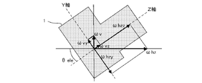
- FIG. 1 is a diagram defining an axis and rotation of a camera which is an imaging device according to an embodiment.
- the X-axis, the Y-axis, the Z-axis, the Pitch rotation, the Yaw rotation, and the Roll rotation are defined as follows.
- the state in which the user holds the camera 1 horizontally is the positive posture
- the horizontal and vertical directions of the camera 1 at that time are the X-axis and the Y-axis of the camera 1
- the optical axis direction of the camera 1 is the Z of the camera 1.
- the rotation of the camera 1 around the X axis is defined as the Pitch rotation
- the rotation of the camera 1 around the Y axis is defined as the Yaw rotation
- the rotation of the camera 1 around the Z axis is defined as the Roll rotation.
- the rotation direction around the X axis of the camera 1 is called the Pitch direction
- the rotation direction around the Y axis of the camera 1 is called the Yaw direction
- the rotation direction around the Z axis of the camera 1 is called the Roll direction.
- FIG. 2 is a diagram showing the effect of rotation at a position on the earth.
- the rotation axis (earth's axis) of rotation has an inclination of ⁇ lat degree with respect to the horizontal. Therefore, the rotation vector ( ⁇ rot ) of rotation can be decomposed into the rotation vector ( ⁇ h ) on the horizontal axis and the rotation vector ( ⁇ v ) on the vertical axis as shown in the following equations (1) and (2). it can.
- ⁇ v ⁇ rot ⁇ SIN ⁇ lat equation (1)
- ⁇ h ⁇ rot ⁇ COS ⁇ lat equation (2)
- FIG. 3 is a diagram showing the effect of rotation depending on the orientation of the optical axis of the camera 1 in the normal posture.
- the above-mentioned rotation vector ( ⁇ h ) is further rotated around the Z axis of the camera 1 as shown in the following equations (3) and (4). It can be decomposed into a vector ( ⁇ hz ) and a rotation vector around the X axis ( ⁇ hx).
- FIG. 4 is a diagram further showing the influence of rotation depending on the posture (elevation angle) of the camera 1.
- the camera 1 A rotation vector around the Z axis ( ⁇ z ) and a rotation vector around the Y axis ( ⁇ y' ) are obtained.
- FIG. 5 is a diagram further showing the effect of rotation depending on the posture (tilt around the optical axis) of the camera 1.
- the rotation vector ( ⁇ hx ) and the rotation vector ( ⁇ y' ) described above are shown in the following equations (7) and (8).
- the rotation vector ( ⁇ x ) around the X axis and the rotation vector ( ⁇ y ) around the Y axis of the camera 1 are obtained.
- ⁇ x ⁇ rot ⁇ COS ⁇ lat ⁇ SIN ⁇ direction ⁇ COS ⁇ slope - ( ⁇ rot ⁇ SIN ⁇ lat ⁇ COS ⁇ ele - ⁇ rot ⁇ COS ⁇ lat ⁇ COS ⁇ direction ⁇ SIN ⁇ ele) ⁇ SIN ⁇ slope formula (9)
- ⁇ y ⁇ rot ⁇ COS ⁇ lat ⁇ SIN ⁇ direction ⁇ SIN ⁇ slope + ( ⁇ rot ⁇ SIN ⁇ lat ⁇ COS ⁇ ele ⁇ rot ⁇ COS ⁇ lat ⁇ COS ⁇ direction ⁇ SIN ⁇ ele ) ⁇ COS ⁇ slope equation (10)
- ⁇ z ⁇ rot ⁇ COS ⁇ lat ⁇ COS ⁇ direction ⁇ COS ⁇ ele + ⁇ rot ⁇ SIN ⁇ lat ⁇ SIN ⁇ ele Equation (11)
- the effect of the rotation of the earth on each axis of the camera 1 changes depending on the latitude, attitude (elevation angle, inclination around the optical axis) of the camera 1, and the direction in which it is facing.
- the direction in which the camera 1 is facing is also the shooting direction, the imaging direction, and the direction of the optical axis of the camera 1.
- the reference value of the angular velocity sensor provided in the camera 1 (the output value of the angular velocity sensor when not rotating) is obtained on the earth, the reference value including the influence of rotation is obtained.
- This reference value will be referred to as the rest reference below.
- the output value of the angular velocity sensor at rest excluding the influence of rotation, will be referred to as the sensor reference value below.
- the angular velocity (rotational velocity) including the rotation can be obtained.
- the image stabilization mechanism By performing image stabilization with the image stabilization mechanism based on this angular velocity, it becomes possible to photograph nebulae and stars, which are extraterrestrial subjects, without being affected by diurnal motion.
- FIG. 6 is a block diagram showing a configuration of a camera which is an imaging device according to the first embodiment.
- the camera 1 includes an optical system 2, an image sensor 3, a drive unit 4, a system controller 5, a blur correction microcomputer 6, an angular velocity sensor 7, an acceleration sensor 8, an orientation sensor 9, a position sensor 10, and an EVF ( Electronic View Finder) 11 and operation switch unit (operation SW unit) 12 are included.
- EVF Electronic View Finder
- the optical system 2 forms an image on the image pickup surface of the image pickup device 3 using the luminous flux from the subject as a subject image.
- the optical system 2 is composed of, for example, a plurality of lenses including a focus lens and a zoom lens. In this case, the movement of the focus lens or the like is performed by driving a lens driving mechanism (not shown) under the control of the system controller 5.
- the image sensor 3 converts the subject image imaged on the image pickup surface by the optical system 2 into an electric signal that becomes a pixel signal.
- the image sensor 3 is, for example, an image sensor such as a CCD (charge coupled device) or a CMOS (complementary metal oxide semiconductor).
- the drive unit 4 is a drive mechanism that moves the image sensor 3 in a direction parallel to the image pickup surface (which is also a direction perpendicular to the optical axis of the optical system 2), and moves the image sensor 3 in translation or rotation. It is possible to do it.
- the drive unit 4 includes a plurality of actuators for moving the image pickup device 3.
- the plurality of actuators are, for example, VCM (Voice Coil Motor).
- the system controller 5 reads out the electric signal converted by the image sensor 3 as image data, and performs various image processing on the read image data. Further, the image processed image data is displayed on the EVF 11 or recorded in a memory (for example, a removable recording medium such as a memory card) (not shown). Further, the system controller 5 controls the entire camera including reading the detection result from the directional sensor 9 and the position sensor 10 and data communication with the blur correction microcomputer 6.
- the angular velocity sensor 7 detects the angular velocities of the camera 1 in the Pitch direction, the Yaw direction, and the Roll direction (rotational motion applied to the X-axis, Y-axis, and Z-axis of the camera 1).
- the acceleration sensor 8 detects accelerations that occur in the X, Y, and Z directions of the camera 1 (acceleration applied in parallel to the X, Y, and Z axes of the camera 1).
- the blur correction microcomputer 6 calculates the amount of image movement generated on the image pickup surface of the image pickup element 3 based on the detection result of the angular velocity sensor 7, and moves the image pickup element 3 in a direction that cancels the image movement corresponding to the image movement amount. Controls the drive unit 4. The blur correction microcomputer 6 also determines the posture of the camera 1 based on the detection result of the acceleration sensor 8.
- the azimuth sensor 9 detects the azimuth (azimuth) of the shooting direction (imaging direction) of the camera 1.
- the azimuth sensor 9 is, for example, a geomagnetic sensor.
- the position sensor 10 detects the position of the camera 1 (including at least the latitude).
- the position sensor 10 is, for example, a GPS (Global Positioning System) sensor.
- the GPS sensor detects the position (latitude, longitude, etc.) by receiving radio waves from a plurality of satellites.
- the EVF 11 displays an image according to the image data, a menu screen that enables various settings for the camera 1 by the user, and the like.
- the operation switch unit 12 includes various switches such as a switch for performing a release operation which is a shooting start instruction and a switch for performing an operation according to the menu screen displayed on the EVF 11.
- the switch included in the operation switch unit 12 the user can, for example, set the shooting mode to the normal shooting mode (hereinafter referred to as "normal mode") or enable the astronomical shooting mode (hereinafter referred to as "normal mode"). It can be set to (hereinafter referred to as "celestial body mode").
- the shooting mode is an example of an operation mode
- the normal mode is an example of the first mode
- the celestial body mode is an example of the second mode.
- the operation switch unit 12 may include a mode dial capable of switching the shooting mode to the normal mode or the celestial body mode.
- the system controller 5 and the blur correction microcomputer 6 may be configured by, for example, a dedicated circuit such as an ASIC (Application Specific Integrated Circuit) or an FPGA (Field-Programmable Gate Array).
- a dedicated circuit such as an ASIC (Application Specific Integrated Circuit) or an FPGA (Field-Programmable Gate Array).
- the system controller 5 and the blur correction microcomputer 6 include a processor such as a CPU and a memory, and the processor executes a program recorded in the memory, the functions of the system controller 5 and the blur correction microcomputer 6 are realized. Good.
- FIG. 7 is a block diagram showing a functional configuration of the blur correction microcomputer 6.
- the blur correction microcomputer 6 includes SIO (Serial Input / Output) 601, communication unit 602, reference value subtraction unit 603, correction amount calculation unit 604, drive control unit 605, SIO606, and posture determination unit 607. It includes a sensor reference value calculation unit 608, a stationary reference value holding unit 609, a sensor reference value holding unit 610, and a switching unit 611.
- the SIO601 is a digital serial interface, and reads out the detection results of the angular velocities in the Pitch direction, the Yaw direction, and the Roll direction from the angular velocity sensor 7 at a constant cycle.
- the communication unit 602 communicates with the system controller 5 to acquire information such as the focal length 602a, the azimuth (azimuth) 602b which is the detection result of the azimuth sensor 9, and the latitude 602c which is the detection result of the position sensor 10. Receive instructions such as the start and end of image stabilization.
- the instructions for starting and ending the image stabilization are also instructions for starting and ending the operation of the image stabilization microcomputer 6.
- the reference value subtracting unit 603 sets the reference value at rest from the angular velocity read out by the SIO 601 for each rotation direction in the Pitch direction, the Yaw direction, and the Roll direction.
- the resting reference value held by the holding unit 609 is subtracted to remove the offset noise.
- the stationary reference value holding unit 609 uses the angular velocities in the Pitch direction, the Yaw direction, and the Roll direction, which are the detection results of the angular velocity sensor 7 when the camera 1 is in a stationary state (specifically, in a stationary state with respect to the ground). It is a memory that holds a certain resting reference value, and the resting reference value is a value including an angular velocity component due to rotation.
- the reference value subtracting unit 603 will be described later from the angular velocity read out by the SIO 601 for each rotation direction in the Pitch direction, the Yaw direction, and the Roll direction when the celestial body mode is set as the shooting mode.
- the sensor reference value held in the sensor reference value holding unit 610 is subtracted.
- the correction amount calculation unit 604 calculates the image movement amount on the imaging surface based on the angular velocities in the Pitch direction, the Yaw direction, and the Roll direction, which are the subtraction results of the reference value subtraction unit 603, and the image movement by the image movement amount. Calculate the correction amount (image blur correction amount) for canceling. Specifically, the angular velocity in the Pitch direction, which is the subtraction result of the reference value subtraction unit 603, is multiplied by the focal length 602a to calculate the image movement velocity on the imaging surface, and the image movement in the Y-axis direction is integrated by time integration. The amount is calculated, and the correction amount for canceling the image movement corresponding to the image movement amount is calculated.
- the angular velocity in the Yaw direction which is the subtraction result of the reference value subtraction unit 603, is similarly multiplied by the focal length 602a to calculate the image movement velocity on the imaging surface, and the image in the X-axis direction is integrated over time.
- the movement amount is calculated, and the correction amount for canceling the image movement corresponding to the image movement amount is calculated.
- the angular velocity in the Roll direction which is the subtraction result of the reference value subtraction unit 603, is time-integrated without multiplying the focal length 602a to calculate the image rotation movement amount (rotational movement amount of the subject image). Then, the correction amount for canceling the image rotation movement corresponding to the image rotation movement amount is calculated.
- the reason why the focal length 602a is not multiplied is that the image rotation movement amount obtained by time-integrating the angular velocity in the Roll direction becomes the rotation movement amount of the subject image around the optical axis.
- the drive control unit 605 controls the drive of the drive unit 4 based on the correction amount which is the calculation result of the correction amount calculation unit 604 to move the image sensor 3. Thereby, for example, it is possible to prevent the occurrence of blurring that may occur in the captured image due to handheld shooting in the normal mode.
- the switching unit 611 switches the input and outputs it according to the set shooting mode. Specifically, when the normal mode is set, the stationary reference value held in the stationary reference value holding unit 609 is input, and when the celestial body mode is set, it is held in the sensor reference value holding unit 610. The sensor reference value is input and output.
- the SIO606 is a digital serial interface, and reads out the acceleration applied in the directions of the three axes of the X-axis, the Y-axis, and the Z-axis, which are the detection results, from the acceleration sensor 8. It should be noted that this acceleration includes a gravity component.
- the posture determination unit 607 detects the direction of gravity from the acceleration applied in the directions of the three axes read out by the SIO 606, and determines the attitude of the camera 1.
- the postures determined here are at least the elevation angle of the camera 1 ( see ⁇ ele in FIG. 4) and the inclination around the optical axis ( see ⁇ slope in FIG. 5).
- the sensor reference value calculation unit 608 uses the above equations (9), (10), and (11) to determine the posture (elevation angle, tilt around the optical axis) of the camera 1 determined by the posture determination unit 607. From the azimuth 602b and the latitude 602c, the rotation angular velocities in the Pitch direction, the Yaw direction, and the Roll direction generated in the camera 1 due to the rotation are calculated. Then, the sensor reference value is calculated by subtracting the calculated rotation angular velocity from the stationary reference value held in the stationary reference value holding unit 609 for each rotation direction in the Pitch direction, Yaw direction, and Roll direction. ..
- the sensor reference value holding unit 610 is a memory that holds the sensor reference values in the Pitch direction, the Yaw direction, and the Roll direction, which are the calculation results of the sensor reference value calculation unit 608.
- FIG. 8 is a flowchart showing the flow of the sensor reference value calculation process performed by the blur correction microcomputer 6.
- the attitude determination unit 607 first detects the direction of gravity from the acceleration applied in the directions of the three axes of the X-axis, the Y-axis, and the Z-axis acquired from the acceleration sensor 8.
- the posture (elevation angle, inclination around the optical axis) of the camera 1 is determined based on the direction of gravity (S11).
- the sensor reference value calculation unit 608 uses the above equations (9), (10), and (11) to determine the attitude (elevation angle, tilt around the optical axis) of the camera 1 determined by the attitude determination unit 607. ), The orientation 602b, and the latitude 602c, the rotation angular velocities in the Pitch direction, the Yaw direction, and the Roll direction generated in the camera 1 due to the rotation are calculated (S12).
- the elevation angle, the inclination around the optical axis, the orientation 602b, and the latitude 602c of the camera 1 correspond to ⁇ ele , ⁇ slope , ⁇ direction , and ⁇ lat , and the Pitch direction, the Yaw direction, and the Yaw direction that occur in the camera 1 due to the rotation.
- the rotation angular velocity in the Roll direction corresponds to ⁇ x , ⁇ y , and ⁇ z.
- the sensor reference value calculation unit 608 holds the rotation angular velocity (rotation component) calculated in S12 for each rotation direction in the Pitch direction, Yaw direction, and Roll direction in the stationary reference value holding unit 609. Subtracting from the stationary reference value (S13), the process ends. According to this, the sensor reference values in the Pitch direction, the Yaw direction, and the Roll direction are calculated and held by the sensor reference value holding unit 610.
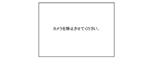
- the calculation process of such a sensor reference value is first performed as a calibration process when the celestial body mode is set as the shooting mode. Since the calibration process needs to be performed with the camera 1 stationary, a notification may be given to the user to urge the camera 1 to be stationary prior to this process. This notification may be made, for example, by display or voice. When this notification is performed by display, for example, the screen shown in FIG. 9 may be displayed on the EVF 11. Alternatively, when this notification is performed by voice, the camera 1 may further include a voice output device including a speaker or the like, and the voice output device may be made to perform the notification by voice. In this case, the EVF 11 and the voice output device are examples of the notification device that notifies the user.
- the image blur correction is performed as the shaking of the camera 1 including the influence of the rotation, so that the astronomical image is taken by holding the camera 1 by hand. Even if it does, astronomical photography that follows the diurnal motion becomes possible, and the stars will not flow and be photographed. Further, as compared with the conventional technique, complicated calculation for astronomical photography is not required, and astronomical follow-up photography can be performed even in the vicinity of the zenith without deteriorating the accuracy.
- the camera 1 may acquire the latitude from an external device.
- the camera 1 may communicate with a mobile information terminal such as a smartphone owned by the user and acquire the latitude detected by the position sensor (for example, GPS sensor) included in the mobile information terminal as the latitude of the camera 1.
- the position sensor for example, GPS sensor
- the camera 1 does not need to include the position sensor 10.
- FIG. 10 is a block diagram showing a configuration of a camera which is an imaging device according to a second embodiment. Since the camera 1 according to the second embodiment does not calculate the sensor reference value, information on the posture (elevation angle, inclination around the optical axis), orientation, and latitude of the camera 1 is unnecessary. Therefore, the camera 1 according to the second embodiment does not include the acceleration sensor 8, the direction sensor 9, and the position sensor 10 as shown in FIG. Instead, it includes a temperature control unit 13 and a temperature sensor 14.
- the temperature control unit 13 is a device that heats or cools the angular velocity sensor 7, and is, for example, a Peltier element.
- the Peltier element is a device that can freely heat and cool depending on the direction in which an electric current flows.
- the temperature sensor 14 detects the temperature of the angular velocity sensor 7 (specifically, the sensor element of the angular velocity sensor 7). It is desirable that the temperature sensor 14 is integrally formed with the angular velocity sensor 7 in order to detect the temperature more accurately.
- the blur correction microcomputer 6 when the celestial body mode is set and the temperature of the angular velocity sensor 7 is further acquired by the sensor reference value held by the sensor reference value holding unit 610.
- the temperature control unit 13 is controlled based on the detection result of the temperature sensor 14 in order to maintain the temperature of the angular velocity sensor 7.
- the sensor reference value acquired in the adjustment process at the time of manufacturing the camera 1 and the temperature of the angular velocity sensor 7 at the time of acquisition are held in the sensor reference value holding unit 610.
- the sensor reference value is obtained from the angular velocity detected by the angular velocity sensor 7 when the camera 1 is in a stationary state in each rotation direction of the camera 1, for example, the Pitch direction, the Yaw direction, and the Roll direction in the adjustment step. , Obtained by removing the rotation angular velocity component generated in the camera 1 due to rotation.
- the rotation angular velocity component may be calculated using the above equations (9), (10), and (11), for example, as in the first embodiment.
- FIG. 11 is a block diagram showing a functional configuration of the blur correction microcomputer 6 according to the second embodiment.
- the difference from the first embodiment is that instead of having a configuration related to the calculation of the sensor reference value, a temperature acquisition unit 612 and a temperature control unit 613 are provided, and the SIO601 is further provided with a temperature sensor. This is a point at which the detected value is read from 14.
- the temperature acquisition unit 612 converts the detected value read from the temperature sensor 14 by the SIO 601 into a temperature (temperature value).
- the temperature control unit 613 is the temperature converted by the temperature acquisition unit 612 in order to maintain the temperature of the angular velocity sensor 7 at the temperature of the angular velocity sensor 7 at the time of acquiring the sensor reference value, which is held by the sensor reference value holding unit 610.
- the temperature control unit 13 is controlled based on the value.
- the temperature (temperature value) converted by the temperature acquisition unit 612 is compared with the temperature of the angular velocity sensor 7 held in the sensor reference value holding unit 610 at the time of sensor reference value acquisition, and the former
- the temperature control unit 13 is controlled to heat the angular velocity sensor 7, and conversely, when the temperature is higher, the temperature control section 13 is controlled to cool the angular velocity sensor 7.
- the control of the temperature control unit 13 may be stopped.
- the temperature of the angular velocity sensor 7 constant (the temperature at the time of acquiring the sensor reference value)
- the temperature drift of the angular velocity sensor 7 can be suppressed. It is possible to detect the rotation angular velocity generated in the camera 1 by the rotation with high accuracy. Further, in the present embodiment, it is not necessary to provide a configuration related to the calculation of the sensor reference value such as the acceleration sensor 8, the direction sensor 9, the position sensor 10, and the like, so that the product cost of the camera 1 can be suppressed.
- FIG. 12 is a block diagram showing a configuration of a camera which is an imaging device according to a third embodiment.
- the difference from the first embodiment is that the acceleration sensor 8, the directional sensor 9, and the position sensor 10 are not provided.
- the camera 1 according to the third embodiment has a calibration mode as an operation mode, and when the calibration mode is set, the influence of rotation while prompting the user to sequentially switch the posture of the camera 1.
- the reference value in the rotation direction that is not affected by the sensor is sequentially acquired as the sensor reference value. According to this, the sensor reference value of each rotation direction of the Pitch direction, the Yaw direction, and the Roll direction is acquired.
- FIG. 13 is a block diagram showing a functional configuration of the blur correction microcomputer 6 according to the third embodiment. As shown in FIG. 13, the difference from the first embodiment is that the configuration related to the calculation of the sensor reference value is not provided. Instead, in the third embodiment, the resting reference value acquired when the calibration mode is set is held as it is in the sensor reference value holding unit 610 as the sensor reference value.
- FIG. 14 is a flowchart showing the flow of the calibration process.
- FIG. 15 is an example of a screen displayed on the EVF 11 during execution of the calibration process.
- the calibration process starts when the calibration mode is set.
- the calibration mode is set, for example, according to the operation of the operation switch unit 12 by the user.
- the camera 1 first displays the screen 11a shown in FIG. 15 on the EVF 11 and prompts the user to stop the camera 1 in the north-facing positive posture (S21).
- the influence of rotation does not occur in the Pitch direction of the camera 1.
- the camera 1 detects the switch operation and then operates.
- the angular velocity in the Pitch direction detected by the angular velocity sensor 7 is acquired and held in the sensor reference value holding unit 610 as the sensor reference value in the Pitch direction (S22).
- the camera 1 displays the screen 11b shown in FIG. 15 on the EVF 11 and prompts the user to stop the camera 1 in a vertical posture facing north (S23).
- the vertical posture is a posture in which the X-axis of the camera 1 is perpendicular to the horizontal plane.
- the camera 1 detects the switch operation and then the Yaw direction detected by the angular velocity sensor 7.
- the angular velocity of is acquired and held in the sensor reference value holding unit 610 as the sensor reference value in the Yaw direction (S24).
- the influence of rotation does not occur in the Yaw direction of the camera 1.
- the camera 1 displays the screen 11c shown in FIG. 15 on the EVF 11 and prompts the user to stop the camera 1 in a positive posture facing east (S25).
- a positive posture facing east S25.
- the camera 1 detects the switch operation and then the Roll direction detected by the angular velocity sensor 7.
- the angular velocity of the above is acquired and held in the sensor reference value holding unit 610 as the sensor reference value in the Roll direction (S26), and the process is completed.
- the sensor reference values in the Pitch direction, the Yaw direction, and the Roll direction are held by the sensor reference value holding unit 610.
- the sensor reference value holding unit 610 can hold the sensor reference value corresponding to the aged deterioration of the angular velocity sensor 7.
- the camera 1 may be provided with the acceleration sensor 8 and the direction sensor 9, and it may be automatically determined that the camera 1 is in the posture according to the display screen in the above calibration process.
- the above-mentioned calibration process may be performed first each time the celestial body mode is set. Further, when the calibration process is completed, the calibration mode may be automatically switched to another mode (for example, an astronomical mode).
- the user is notified to urge the posture of the camera 1 by the display of the EVF 11, but the present invention is not limited to this.
- the camera 1 further includes an audio output device including a speaker and the like, and depends on the voice. A notification prompting the posture of the camera 1 may be given.
- the EVF 11 and the voice output device are examples of the notification device that notifies the user.
- FIG. 16 is a block diagram showing a functional configuration of the blur correction microcomputer 6 according to a modified example of the third embodiment.
- the blur correction microcomputer 6 further includes a switching unit 616, a tripod determination unit 617, and an LPF (Low Pass Filter) 618.
- the tripod determination unit 617 determines whether or not the camera 1 is installed on the tripod based on the amplitude of the angular velocity which is the subtraction result of the reference value subtraction unit 603. Specifically, when the amplitude of the angular velocity is equal to or less than a predetermined amplitude, it is determined that the state is installed on a tripod, and when not, it is determined that the state is not installed on a tripod.
- the determination made by the tripod determination unit 617 is also to determine whether or not the camera 1 is fixed.
- the LPF618 performs LPF processing on the angular velocities in the Pitch direction, the Yaw direction, and the Roll direction, which are the subtraction results of the reference value subtracting unit 603. This makes it possible to block high frequency noise components.
- the LPF618 is an example of a filter circuit that performs a filter process for blocking high frequency components.
- the switching unit 616 switches the input and outputs it according to the determination result of the tripod determination unit 617. Specifically, when the tripod determination unit 617 determines that the camera 1 is installed on a tripod, the processing result of LPF618 is input, and the tripod determination unit 617 is not installed on the tripod. If the determination is made according to the above, the subtraction result of the reference value subtraction unit 603 is input and output.
- the reason for switching such inputs is that when the camera 1 is installed on a tripod (that is, fixed), the angular velocity generated in the camera 1 is only the angular velocity due to the rotation (rotation angular velocity), and this rotation angular velocity. In this case, LPF processing is performed to prevent image blur correction whose accuracy is lowered due to the influence of random noise such as readout noise.
- FIG. 17 is a block diagram showing a functional configuration of the blur correction microcomputer 6 according to the fourth embodiment.
- the difference from the third embodiment is that it further includes a switching unit 616, a rotation calculation unit 619, and an amplitude determination unit 620.
- the switching unit 616 switches the input and outputs it according to the set shooting mode. Specifically, when the normal mode is set, the subtraction result of the reference value subtraction unit 603 is input, and when the celestial body mode is set, the calculation result of the rotation calculation unit 619 (held by the rotation calculation unit 619). The calculation result) is input and output.
- the rotation calculation unit 619 depends on the reference value subtraction unit 603 for each rotation direction in the Pitch direction, Yaw direction, and Roll direction during a predetermined period (for example, 1 second or more) and determines the sensor reference value. Calculates and holds the average value of the angular velocity subtracted by.
- the angular velocity at which the sensor reference value is subtracted by the reference value subtracting unit 603 is only the rotation angular velocity generated by the camera 1 due to the rotation. Then, by obtaining the average value of the angular velocities from which the sensor reference value is subtracted by the reference value subtracting unit 603 during a predetermined time, the angular velocity sensor 7 has a small S / N (Signal / Noise) ratio (that is, noise is generated). Even with a sensor (many), it is possible to obtain a value with little error. In particular, by lengthening the predetermined time, a value with less error can be obtained.
- the amplitude determination unit 620 determines whether or not the amplitude of the angular velocity, which is the detection result of the angular velocity sensor 7, is equal to or less than a predetermined amplitude.
- the determination result of the amplitude determination unit 620 is notified to the system controller 5 by the communication unit 602.
- the determination result of the amplitude determination unit 620 is used when determining whether or not the vibration generated in the camera 1 is settled by the user's release operation at the start of shooting.
- FIG. 18 is a flowchart showing the flow of control processing related to photographing performed by the system controller 5 according to the fourth embodiment.
- This control process is started by issuing a shooting start instruction by the user's release operation on the operation switch unit 12.
- a shooting start instruction by the user's release operation on the operation switch unit 12.
- an instruction to start shooting a still image is given.
- the celestial body mode is set as the shooting mode.
- the system controller 5 first inquires of the blur correction microcomputer 6 whether or not the vibration accompanying the release operation has converged, and waits until the vibration converges (S31). Since vibration does not occur when the release operation is performed remotely, the process of S31 may be omitted.
- the amplitude determination unit 620 determines whether or not the angular velocity, which is the detection result of the angular velocity sensor 7, is equal to or less than a predetermined amplitude. Then, when the blur correction microcomputer 6 notifies the determination result by the amplitude determination unit 620 that the amplitude is equal to or less than a predetermined amplitude, the system controller 5 instructs the blur correction microcomputer 6 to calculate the rotation speed (S32).
- the rotation calculation unit 619 calculates and holds the average value of the angular velocities obtained by subtracting the sensor reference value by the reference value subtraction unit 603 during a predetermined period in response to the instruction.
- the system controller 5 instructs the blur correction microcomputer 6 to start the rotation correction (S33).
- the switching unit 616 performs input switching using the input as the calculation result of the rotation calculation unit 619 (calculation result held in the rotation calculation unit 619). Then, the correction amount calculation unit 604 calculates the correction amount in the same manner from the average value of the rotation angular velocities calculated and held by the rotation calculation unit 619 for each rotation direction in the Pitch direction, the Yaw direction, and the Roll direction.
- the blur correction microcomputer 6 starts image blur correction related to rotation, such as the drive control unit 605 driving the drive unit 4 based on the correction amount.
- the system controller 5 exposes the still image (S34), and when the exposure is completed, reads out the electric signal converted by the image sensor 3 as image data to acquire the captured image (S35), and corrects the blur.
- the microcomputer 6 is instructed to end the rotation correction (S36), and the process ends.
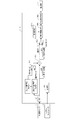
- FIG. 19 is a timing chart showing an operation example of the image sensor 3, the blur correction microcomputer 6, and the drive unit 4 according to the fourth embodiment.
- the image sensor 3 is exposed for live view during the shooting standby (for example, before the shooting start instruction).
- the image stabilization microcomputer 6 performs an image stabilization operation such as calculating a correction amount suitable for live view and controlling the drive of the drive unit 4.
- the correction position is moved by a camera shake correction operation suitable for live view.
- FIG. 19 shows a change in the correction position of the drive unit 4 as an operation of the drive unit 4.
- the image sensor 3 is shielded from light by the front curtain of a shutter (not shown). At this time, the dark current of the image sensor 3 may be acquired, and the dark current portion may be subtracted later. Further, when the configuration does not include the front curtain, the image sensor 3 may be maintained in the reset state.
- the image sensor 3 starts the still image exposure.
- the blur correction microcomputer 6 calculates the correction amount (rotation correction amount) from the average value (rotation angular velocity) calculated by the rotation calculation unit 619 by the integration or the like by the correction amount calculation unit 604.
- the correction position moves at a constant speed based on the rotation correction amount, and the movement of the celestial body imaged on the image sensor 3 due to the diurnal motion is canceled out, and the image sensor 3 The image pickup position of the subject image is maintained.
- the image sensor 3 is shielded from light by the rear curtain of a shutter (not shown), and the image data is read out from the image sensor 3.
- the blur correction microcomputer 6 the correction amount is cleared, and the correction position of the drive unit 4 moves to the initial position.
- the rotation calculation unit 619 may be performed while waiting for shooting.
- FIG. 20 is a block diagram showing a functional configuration of the blur correction microcomputer 6 according to the fifth embodiment.
- the difference from the first embodiment is that the rotation angular velocity calculation unit 621 is provided instead of the sensor reference value calculation unit 608 and the sensor reference value holding unit 610.
- the rotation angular velocity calculation unit 621 uses the above equations (9), (10), and (11) to determine the posture (elevation angle, tilt around the optical axis) and orientation of the camera 1 determined by the posture determination unit 607. From 602b and the latitude 602c, the rotation angular velocities in the Pitch direction, the Yaw direction, and the Roll direction generated in the camera 1 due to the rotation are calculated.
- the rotation angular velocity calculation unit 621 includes a memory that holds the calculated rotation angular velocity in each rotation direction.
- the reference value subtracting unit 603 is held by the stationary reference value holding unit 609 from the angular velocity read out by the SIO 601 in each rotation direction of the Pitch direction, the Yaw direction, and the Roll direction. Subtract the reference value at rest.
- the switching unit 611 switches the input and outputs it according to the set shooting mode. Specifically, when the normal mode is set, the subtraction result of the reference value subtraction unit 603 is input, and when the celestial body mode is set, the calculation result of the rotation angular velocity calculation unit 621 is input and output. According to this, when the celestial body mode is set, the image blur correction is performed based on the rotation angular velocity generated in the camera 1 due to the rotation.
- the angular velocity sensor 7 does not have the sensitivity to detect the rotation angular velocity, it is possible to perform imaging following the celestial body.
- the calculation load is smaller than that of the conventional technique, and astronomical tracking photography can be performed even near the zenith without deteriorating the accuracy.
- a sixth embodiment is a camera system including an information processing terminal such as a smartphone or tablet and a camera, and a user can perform astronomical photography by operating the camera using the information processing terminal.
- the information processing terminal is specified from the coordinates of the specified celestial body, the current date and time, and the latitude of the current position of the information processing terminal.
- the direction and altitude (elevation angle) of the celestial body are calculated, and the rotation angle speeds of the Pitch direction, the Yaw direction, and the Roll direction generated in the camera due to the rotation are calculated.
- the information processing terminal notifies the camera installed on the tripod or the like of the calculated rotation angular velocity in each rotation direction, and the camera performs image blur correction based on the notified rotation angular velocity in each rotation direction. This makes it possible to take pictures that follow the celestial body.
- FIG. 21 is a block diagram showing a configuration of a camera which is an imaging device according to a sixth embodiment.
- the same components as those of the other embodiments are designated by the same reference numerals, and the description thereof will be omitted.
- the camera 1 includes an optical system 2, an image sensor 3, a drive unit 4, a system controller 5, a blur correction microcomputer 6, an angular velocity sensor 7, an acceleration sensor 8, and external communication. Including part 15.
- the external communication unit 15 is a communication interface that performs wireless communication with an external device such as an information processing terminal by using Wifi (registered trademark), Bluetooth (registered trademark), or the like.
- the external communication unit 15 receives various instructions such as a shooting instruction from the information processing terminal, and transmits a shot image or a shot video to the information processing terminal.
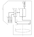
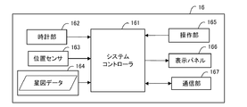
- FIG. 22 is a block diagram showing a configuration of an information processing terminal.
- the information processing terminal 16 includes a system controller 161, a clock unit 162, a position sensor 163, a star map data holding unit 164, an operation unit 165, a display panel 166, and a communication unit 167.
- the system controller 161 controls the entire information processing terminal 16.
- the clock unit 162 has a calendar function and a clock function, and acquires the current date and time.
- the clock unit 162 is an example of a date / time acquisition circuit for acquiring the current date / time.
- the position sensor 163 detects the current position (including at least latitude) of the information processing terminal 16.
- the position sensor 163 is, for example, a GPS sensor.
- the star map data holding unit 164 is a memory for holding star map data in the equatorial coordinate system.
- the operation unit 165 accepts operations for giving various instructions such as instructions to the camera 1.
- the operation unit 165 is a touch panel provided on the front surface of the display panel 166.
- the display panel 166 displays an operation screen of the camera 1 and a star map according to the star map data.
- the display panel is, for example, an LCD (liquid crystal display).
- the communication unit 167 is a communication interface that performs wireless communication between external devices such as the camera 1 by Wifi (registered trademark), Bluetooth (registered trademark), or the like. For example, the communication unit 167 transmits various instructions such as a shooting instruction to the camera 1 and receives a shot image or a shot video from the camera 1.
- the system controller 161 may be configured by, for example, a dedicated circuit such as an ASIC or an FPGA.
- the system controller 161 may include, for example, a processor such as a CPU and a memory, and the function of the system controller 161 may be realized by the processor executing a program recorded in the memory.
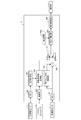
- FIG. 23 is a flowchart showing the flow of control processing related to photographing performed by the system controller 161 of the information processing terminal 16. This process is performed when a shooting instruction is given to the camera 1 from the information processing terminal 16.
- the system controller 161 is first held in the star map data holding unit 164 based on the date and time acquired by the clock unit 162 and the latitude detected by the position sensor 163.
- the star map data of the equatorial coordinate system is converted into the star map data of the horizontal coordinate system (S41).
- the system controller 161 determines as a display area a partial star map including at least a part on the horizon in the star map corresponding to the star map data of the horizontal coordinate system, and displays the determined partial star map as the display area on the display panel 166. (S42).
- the touch position is provided on the front surface of the display panel 166. It is detected by the touch panel (operation unit) 165 and notified to the system controller 161.
- the system controller 161 acquires the horizontal coordinates of the celestial body to be photographed from the partial star map of the horizontal coordinate system displayed on the display panel 166 and the coordinates of the touch position notified from the touch panel (operation unit) 165 (S44). ).
- the system controller 161 acquires the direction and altitude (elevation angle) of the celestial body to be photographed from the acquired horizontal coordinates (S45).
- the system controller 161 calculates the effect of rotation based on the acquired azimuth and altitude (elevation angle) and the latitude detected by the position sensor 163 (S46).
- the effect of rotation is the rotation angular velocity in each rotation direction of the camera 1 in the Pitch direction, Yaw direction, and Roll direction, and the above equations (9), (10), and (11) are used. Can be calculated.
- the ⁇ slope may be set to 0 and the rotation angular velocity may be calculated.
- the system controller 161 notifies the camera 1 of the shooting start instruction together with the calculated effect of the rotation (S47).
- the system controller 161 determines whether or not the exposure time has elapsed (S48), and waits until the exposure time elapses.
- the shooting is bulb shooting, it is determined whether or not the operation of the shooting end instruction by the user has been accepted, and the process waits until the operation is accepted.
- the system controller 161 notifies the camera 1 of the shooting end instruction (S49), and the process ends.
- FIG. 24 is a block diagram showing a functional configuration of the blur correction microcomputer 6 according to the sixth embodiment.
- the blur correction microcomputer 6 according to the present embodiment holds the rotation angular velocity (effect of the above-mentioned rotation) notified from the information processing terminal 16 instead of calculating the rotation angular velocity inside the camera 1.
- a rotation angular velocity holding unit 622 provided with a memory is provided. According to this, in the celestial body mode, the rotation angular velocity held by the rotation angular velocity holding unit 622 is output to the correction amount calculation unit 604 by the input switching by the switching unit 611.
- the rotation angular velocity holding unit 622 corrects the held rotation angular velocity based on the inclination around the optical axis, if there is an inclination around the optical axis from the attitude determined by the attitude determination unit 607. For example, as described above, even if it is assumed that the shooting is performed in a state where the camera 1 is not tilted around the optical axis, the actual state is such that the camera 1 is not tilted around the optical axis. This is because it may not be.
- the influence of the rotation is calculated by the external information processing terminal 16, it is not necessary to perform complicated calculation in the camera 1. Further, since the celestial body to be photographed is specified from the star map, the direction and elevation angle (altitude) of the celestial body to be photographed can be accurately acquired.
- the inclination around the optical axis of the camera 1 used when the system controller 161 of the information processing terminal 16 calculates the influence of the rotation may be acquired from the camera 1.
- the information processing terminal 16 communicates with the camera 1, and the posture (inclination around the optical axis) of the camera 1 determined by the posture determination unit 607 of the camera 1 is acquired from the camera 1.
- the image blur correction is performed by the drive control unit 605 driving and controlling the drive unit 4 to move the image sensor 3, but the camera 1 is provided with a part of the lenses of the optical system 2.
- a drive mechanism for moving the lens in a direction orthogonal to the optical axis is further provided, and the drive control unit 605 controls the drive mechanism and the drive unit 4 to move a part of the lens and the image sensor 3.
- Image blur correction may be performed depending on the above. In this case, for example, a part of the lenses may be translated and the image sensor 3 may be rotationally moved, or a part of the lenses may be translated and the image sensor 3 may be translated and rotated. ..
- the first or second embodiment may be combined with the third embodiment.
- the control may be performed based on the third embodiment, and if not, the control may be performed based on the first or second embodiment.
- the sensor reference value was acquired in the adjustment step at the time of manufacturing, but the sensor reference value acquired by the method described in the third embodiment and the temperature of the angular velocity sensor 7 at that time are obtained. It may be used while being held by the sensor reference value holding unit at 610.
- the rotation angular velocity which is the output of the communication unit 602 of the sixth embodiment may be input instead of the direction 602b and the latitude 602c. That is, the sensor reference value calculation unit 608 of the first embodiment rotates from the attitude (elevation angle, inclination around the optical axis) of the camera 1 determined by the attitude determination unit 607, the direction 602b, and the latitude 602c. The rotation angular velocity in each rotation direction in the Pitch direction, the Yaw direction, and the Roll direction generated in the camera 1 is calculated according to the above. On the other hand, the sensor reference value calculation unit 608 may use the rotation angular velocity which is the output of the communication unit 602 without calculating the rotation angular velocity.
Landscapes
- Engineering & Computer Science (AREA)
- Multimedia (AREA)
- Signal Processing (AREA)
- Physics & Mathematics (AREA)
- General Physics & Mathematics (AREA)
- Aviation & Aerospace Engineering (AREA)
- Human Computer Interaction (AREA)
- Adjustment Of Camera Lenses (AREA)
- Studio Devices (AREA)
Abstract
This imaging device comprises: an optical system which forms a subject image on an imaging element; an angular velocity sensor which detects angular velocities in a plurality of rotation directions; a first memory which holds, as a reference value, the angular velocities in the plurality of rotation directions detected by the angular velocity sensor when the imaging device is stationary with respect to the ground; a second memory which holds rotation angular velocities in a plurality of rotation directions that occur in the imaging device due to the rotation of the earth; a subtraction circuit which subtracts a reference value held in the first memory from the angular velocity detected by the angular velocity sensor, for each rotation direction in the plurality of rotation directions; a circuit which calculates an image blur correction amount to cancel the blurring of the subject image imaged on the image sensor, on the basis of the subtraction result of the subtraction circuit or the rotation angular velocities in the plurality of rotation directions held in the second memory, according to an operation mode of the imaging device; and a drive control circuit which drives a first drive mechanism for moving the image sensor or the first drive mechanism and a second drive mechanism for moving a part of the optical system, on the basis of an image blur correction amount.
Description
本発明は、日周運動に追従して天体を撮影する技術に関する。
The present invention relates to a technique for photographing an astronomical object by following diurnal motion.
目視では見ることができない天体をカメラで撮影する場合は、数秒以上の長時間露光が必要であるものの、カメラを三脚等に固定して撮影したとしても露光中に日周運動の影響に依り星が流れてしまう。こういった日周運動の影響は、カメラの焦点距離が長くなるほど大きくなり、星が流れずに撮影できる露光時間も短くなる。
When shooting a celestial body that cannot be seen visually with a camera, long exposure of several seconds or more is required, but even if the camera is fixed to a tripod etc., it depends on the influence of diurnal motion during exposure. Will flow. The effect of such diurnal motion increases as the focal length of the camera increases, and the exposure time that can be taken without the stars flowing also decreases.
例えば、焦点距離1000mmのカメラで星雲を撮影する場合を考える。
地球の自転の回転速度(自転角速度)が約0.004167dps(degree per second)であることから、1秒間に生じる像移動量(カメラの撮像素子に結像される被写体像の移動量)は約73μmになり、特定のカメラシステムのマウント規格に依れば1600万画素のイメージセンサで約20ピクセルに相当する。 For example, consider the case of photographing a nebula with a camera having a focal length of 1000 mm.
Since the rotation speed (rotation angular velocity) of the earth's rotation is about 0.004167 dps (degree per second), the amount of image movement (the amount of movement of the subject image imaged on the image sensor of the camera) that occurs per second is about. It is 73 μm, which is equivalent to about 20 pixels with a 16-megapixel image sensor according to the mounting standard of a specific camera system.
これに依る撮影画像への影響は、カメラの緯度や向き(撮影方向の方位、仰角)に依り変化するものの、上述の撮影条件下では、カメラを静止させた状態で撮影したとしても星が流れてしまう。
The effect of this on the captured image changes depending on the latitude and orientation of the camera (direction of shooting direction, elevation angle), but under the above-mentioned shooting conditions, stars will flow even if the camera is stationary. It ends up.
星が流れずに撮影できる方法の1つとして、赤道儀を使う方法がある。赤道儀は、回転軸を地軸と合わせて地球の自転を打ち消すべく回転することに依り、赤道儀に設置されたカメラの光軸が天体を追従できる構成を有する。
One way to shoot without the stars flowing is to use an equatorial mount. The equatorial mount has a configuration in which the optical axis of the camera installed on the equatorial mount can follow the celestial body by aligning the rotation axis with the earth's axis and rotating to cancel the rotation of the earth.
しかしながら、赤道儀はコストや機材の設置の手間等を考慮すると、手軽に使用できる方法ではない。また、子午線を超えて撮影しようとする場合は、撮影中に設定の変更が必要になる等、様々な問題が生じる。
However, the equatorial mount is not an easy method to use, considering the cost and the trouble of installing equipment. In addition, when shooting beyond the meridian, various problems occur, such as the need to change the settings during shooting.
一方で、カメラ単体で天体撮影を可能にする技術が知られている。例えば、特許文献1には、撮影地点の緯度情報、撮影方位角情報、撮影仰角情報、撮影装置の姿勢情報、及び撮影光学系の焦点距離情報を入力し、その全情報を用いて、天体像を撮像素子の所定の撮像領域に対して固定するための撮影装置に対する相対移動量を算出し、その相対移動量に基づき、所定の撮像領域と天体像の少なくとも一方を移動させて撮影することで、天体に追従した撮影を可能にする技術が開示されている。
On the other hand, the technology that enables astronomical photography with a single camera is known. For example, in Patent Document 1, latitude information of a shooting point, shooting orientation angle information, shooting elevation angle information, posture information of a shooting device, and focal length information of a shooting optical system are input, and all the information is used to form an astronomical image. By calculating the relative movement amount of the image pickup element with respect to the imaging device for fixing the image with respect to the predetermined imaging region, and moving at least one of the predetermined imaging region and the astronomical image based on the relative movement amount, the image is photographed. , A technique that enables shooting that follows an astronomical object is disclosed.
特許文献1に開示の技術では、撮影の度に、撮影地点の緯度情報、撮影方位角情報、撮影仰角情報、撮影装置の姿勢情報、及び撮影光学系の焦点距離情報が入力され、その全情報を用いて相対移動量の算出が行われる。即ち、撮影の度に、こういった複雑な計算が必要になる。また、特許文献1に開示の相対移動量の算出方法では、天頂付近の撮影を行う場合に、算出誤差が大きくなるという問題がある。
In the technique disclosed in Patent Document 1, the latitude information of the shooting point, the shooting azimuth information, the shooting elevation angle information, the posture information of the shooting device, and the focal length information of the shooting optical system are input every time the shooting is performed, and all the information thereof. The relative movement amount is calculated using. That is, such a complicated calculation is required every time a photograph is taken. Further, the method of calculating the relative movement amount disclosed in Patent Document 1 has a problem that the calculation error becomes large when the image near the zenith is taken.
一方で、センサの検出精度は日夜向上しており、特に角速度センサにおいては地球の自転(約0.004167dps)を検出可能な感度を持つものも登場してきている。
本発明は、上記実情に鑑み、複雑な計算を必要とせず、天頂付近でも精度を低下させることなく天体追従撮影を可能にする技術を提供することを目的とする。 On the other hand, the detection accuracy of the sensor is improving day and night, and in particular, an angular velocity sensor having a sensitivity capable of detecting the rotation of the earth (about 0.004167 dps) has appeared.
In view of the above circumstances, it is an object of the present invention to provide a technique that enables astronomical follow-up imaging without requiring complicated calculations and without deteriorating accuracy even in the vicinity of the zenith.
本発明の一態様は、撮像装置であって、被写体像を結像する光学系と、前記光学系に依り結像された被写体像を電気信号に変換する撮像素子と、前記撮像装置の複数の回転方向の角速度を検出する角速度センサと、前記撮像装置が地面に対して静止状態である時の前記角速度センサに依り検出された前記複数の回転方向の角速度を第1基準値として保持する第1メモリと、前記複数の回転方向の各回転方向毎に、前記静止状態である時の前記角速度センサに依り検出された角速度から、地球の自転に依り前記撮像装置に生じる自転角速度の成分を取り除くことに依り取得された、前記複数の回転方向の角速度を第2基準値として保持する第2メモリと、前記複数の回転方向の各回転方向毎に、前記角速度センサに依り検出された角速度から、前記撮像装置の動作モードに応じて、前記第1メモリに保持された第1基準値又は前記第2メモリに保持された第2基準値を減算する減算回路と、前記減算回路の減算結果に基づいて、前記撮像素子に結像された被写体像のぶれを打ち消すための像ぶれ補正量を算出する像ぶれ補正量算出回路と、前記撮像素子を移動させる第1駆動機構、又は、前記光学系の一部を移動させる第2駆動機構及び前記第1駆動機構を、前記像ぶれ補正量に基づいて駆動する駆動制御回路と、を備える。
One aspect of the present invention is an image pickup apparatus, which comprises an optical system for forming a subject image, an image pickup element for converting a subject image formed by the optical system into an electric signal, and a plurality of the image pickup devices. A first reference value is a plurality of angular velocity sensors in the rotational direction detected by the angular velocity sensor that detects the angular velocity in the rotational direction and the angular velocity sensor when the image pickup device is stationary with respect to the ground. For each rotation direction of the plurality of rotation directions, the component of the rotation angle speed generated in the image pickup device due to the rotation of the earth is removed from the angular speed detected by the angular speed sensor in the stationary state. From the second memory that holds the angular velocities in the plurality of rotation directions as the second reference value, and the angular velocities detected by the angular velocity sensor for each rotation direction in the plurality of rotation directions. Based on the subtraction circuit that subtracts the first reference value held in the first memory or the second reference value held in the second memory according to the operation mode of the image pickup apparatus, and the subtraction result of the subtraction circuit. An image blur correction amount calculation circuit for calculating an image blur correction amount for canceling a blur of a subject image imaged on the image pickup element, a first drive mechanism for moving the image pickup element, or one of the optical systems. A second drive mechanism for moving the unit and a drive control circuit for driving the first drive mechanism based on the image blur correction amount are provided.
本発明の他の一態様は、撮像装置であって、被写体像を結像する光学系と、前記光学系に依り結像された被写体像を電気信号に変換する撮像素子と、前記撮像装置の第1回転方向、第2回転方向、及び第3回転方向の角速度を検出する角速度センサと、前記撮像装置が地面に対して静止状態である時の前記角速度センサに依り検出された前記第1回転方向、前記第2回転方向、及び前記第3回転方向の角速度を第1基準値として保持する第1メモリと、前記撮像装置が地面に対して第1姿勢で静止状態である時の前記角速度センサに依り検出された前記第1回転方向の角速度と、前記撮像装置が地面に対して第2姿勢で静止状態である時の前記角速度センサに依り検出された前記第2回転方向の角速度と、前記撮像装置が地面に対して第3姿勢で静止状態である時の前記角速度センサに依り検出された前記第3回転方向の角速度とを第2基準値として保持する第2メモリと、前記第1回転方向、前記第2回転方向、及び前記第3回転方向の各回転方向毎に、前記角速度センサに依り検出された角速度から、前記撮像装置の動作モードに応じて、前記第1メモリに保持された第1基準値又は前記第2メモリに保持された第2基準値を減算する減算回路と、前記減算回路の減算結果に基づいて、前記撮像素子に結像された被写体像のぶれを打ち消すための像ぶれ補正量を算出する像ぶれ補正量算出回路と、前記撮像素子を移動させる第1駆動機構、又は、前記光学系の一部を移動させる第2駆動機構及び前記第1駆動機構を、前記像ぶれ補正量に基づいて駆動する駆動制御回路と、を備える。
Another aspect of the present invention is an image pickup apparatus, which comprises an optical system for forming a subject image, an image pickup element for converting a subject image formed by the optical system into an electric signal, and the image pickup apparatus. The first rotation detected by the angular velocity sensor that detects the angular velocity in the first rotation direction, the second rotation direction, and the third rotation direction, and the angular velocity sensor when the imaging device is stationary with respect to the ground. A first memory that holds the angular velocity in the direction, the second rotational direction, and the third rotational direction as the first reference value, and the angular velocity sensor when the imaging device is stationary in the first posture with respect to the ground. The angular velocity in the first rotation direction detected by the above, the angular velocity in the second rotation direction detected by the angular velocity sensor when the imaging device is stationary in the second posture with respect to the ground, and the above. A second memory that holds the angular velocity in the third rotation direction detected by the angular velocity sensor when the image pickup device is stationary in the third posture with respect to the ground as a second reference value, and the first rotation. The angular velocity detected by the angular velocity sensor in each of the direction, the second rotational direction, and the third rotational direction is held in the first memory according to the operation mode of the image pickup apparatus. A subtraction circuit that subtracts the first reference value or the second reference value held in the second memory, and a subtraction result of the subtraction circuit for canceling blurring of the subject image formed on the image pickup element. The image blur correction amount calculation circuit for calculating the image blur correction amount, the first drive mechanism for moving the image pickup element, or the second drive mechanism and the first drive mechanism for moving a part of the optical system are described. It includes a drive control circuit that drives based on the image blur correction amount.
本発明の更に他の一態様は、撮像装置であって、被写体像を結像する光学系と、前記光学系に依り結像された被写体像を電気信号に変換する撮像素子と、前記撮像装置の複数の回転方向の角速度を検出する角速度センサと、前記撮像装置が地面に対して静止状態である時の前記角速度センサに依り検出された前記複数の回転方向の角速度を基準値として保持する第1メモリと、地球の自転に依り前記撮像装置に生じる前記複数の回転方向の自転角速度を保持する第2メモリと、前記複数の回転方向の各回転方向毎に、前記角速度センサに依り検出された角速度から前記第1メモリに保持された基準値を減算する減算回路と、前記撮像装置の動作モードに応じて、前記減算回路の減算結果、又は、前記第2メモリに保持された前記複数の回転方向の自転角速度に基づいて、前記撮像素子に結像された被写体像のぶれを打ち消すための像ぶれ補正量を算出する像ぶれ補正量算出回路と、前記撮像素子を移動させる第1駆動機構、又は、前記光学系の一部を移動させる第2駆動機構及び前記第1駆動機構を、前記像ぶれ補正量に基づいて駆動する駆動制御回路と、を備える。
Yet another aspect of the present invention is an image pickup apparatus, which comprises an optical system for forming a subject image, an image pickup element for converting a subject image formed by the optical system into an electric signal, and the image pickup apparatus. The angular velocity sensor that detects the angular velocities in the plurality of rotation directions and the angular velocities in the plurality of rotation directions detected by the angular velocity sensors when the imaging device is stationary with respect to the ground are held as reference values. One memory, a second memory that holds the rotation angle velocities in the plurality of rotation directions generated in the image pickup device due to the rotation of the earth, and each rotation direction in each of the plurality of rotation directions were detected by the angular velocity sensor. The subtraction circuit that subtracts the reference value held in the first memory from the angular velocity, the subtraction result of the subtraction circuit, or the plurality of rotations held in the second memory, depending on the operation mode of the imaging device. An image blur correction amount calculation circuit that calculates an image blur correction amount for canceling a blur of a subject image imaged on the image pickup element based on the rotation angular velocity in the direction, and a first drive mechanism for moving the image pickup element. Alternatively, it includes a second drive mechanism for moving a part of the optical system and a drive control circuit for driving the first drive mechanism based on the image blur correction amount.
本発明の更に他の一態様は、情報処理端末と撮像装置を含むシステムであって、前記情報処理端末は、星図データを保持するメモリと、現在日時を取得する日時取得回路と、前記情報処理端末の少なくとも緯度を含む位置を検出する位置センサと、前記現在日時及び前記緯度に基づいて、前記星図データに応じた星図における地平線上の部分を少なくとも含む部分星図を表示エリアとして決定する表示エリア決定回路と、前記表示エリアとして決定された部分星図を表示するディスプレイと、前記ディスプレイに表示された部分星図において撮影対象として指示された天体の地平座標を取得する地平座標取得回路と、前記緯度と、前記天体の地平座標から取得される方位及び仰角とに基づいて、地球の自転に依り前記撮像装置に生じる複数の回転方向の自転角速度を算出する自転角速度算出回路と、前記自転角速度算出回路に依り算出された前記複数の回転方向の自転角速度を前記撮像装置に送信する通信インタフェースと、を備え、前記撮像装置は、被写体像を結像する光学系と、前記光学系に依り結像された被写体像を電気信号に変換する撮像素子と、前記複数の回転方向の角速度を検出する角速度センサと、前記撮像装置が地面に対して静止状態である時の前記角速度センサに依り検出された前記複数の回転方向の角速度を基準値として保持する第1メモリと、前記情報処理端末から送信された前記複数の回転方向の自転角速度を受信する通信インタフェースと、前記通信インタフェースに依り受信された前記複数の回転方向の自転角速度を保持する第2メモリと、前記複数の回転方向の各回転方向毎に、前記角速度センサに依り検出された角速度から前記第1メモリに保持された基準値を減算する減算回路と、前記撮像装置の動作モードに応じて、前記減算回路の減算結果、又は、前記第2メモリに保持された前記複数の回転方向の自転角速度に基づいて、前記撮像素子に結像された被写体像のぶれを打ち消すための像ぶれ補正量を算出する像ぶれ補正量算出回路と、前記撮像素子を移動させる第1駆動機構、又は、前記光学系の一部を移動させる第2駆動機構及び前記第1駆動機構を、前記像ぶれ補正量に基づいて駆動する駆動制御回路と、を備える。
Yet another aspect of the present invention is a system including an information processing terminal and an image pickup device, wherein the information processing terminal includes a memory for holding star map data, a date and time acquisition circuit for acquiring the current date and time, and the information processing. A position sensor that detects a position including at least the latitude of the terminal, and a display area determination that determines a partial star map including at least a part on the horizon in the star map according to the star map data as a display area based on the current date and time and the latitude. The circuit, the display that displays the partial star map determined as the display area, the horizon coordinate acquisition circuit that acquires the horizon coordinates of the celestial body designated as the object to be photographed in the partial star map displayed on the display, the latitude, and the above. Based on the orientation and elevation angle obtained from the horizon coordinates of the celestial body, the rotation angle speed calculation circuit that calculates the rotation angle velocities in a plurality of rotation directions that occur in the image pickup device depending on the rotation of the earth, and the rotation angle speed calculation circuit. A communication interface for transmitting the calculated rotation angle speeds in the plurality of rotation directions to the image pickup device is provided, and the image pickup device includes an optical system for forming a subject image and a subject formed by the optical system. An imaging element that converts an image into an electric signal, an angular velocity sensor that detects the angular velocities in the plurality of rotation directions, and the plurality of angular velocity sensors that are detected by the angular velocity sensor when the imaging device is stationary with respect to the ground. A first memory that holds the angular speed in the rotation direction as a reference value, a communication interface that receives the rotation angle speeds in the plurality of rotation directions transmitted from the information processing terminal, and the plurality of rotations received by the communication interface. A second memory that holds the rotation angle velocity in the direction, and a subtraction circuit that subtracts a reference value held in the first memory from the angular velocity detected by the angular velocity sensor for each rotation direction in the plurality of rotation directions. An image of a subject imaged on the image pickup element based on the subtraction result of the subtraction circuit or the rotation angle velocities in the plurality of rotation directions held in the second memory, depending on the operation mode of the image pickup device. An image blur correction amount calculation circuit that calculates an image blur correction amount for canceling the blur, a first drive mechanism that moves the image pickup element, or a second drive mechanism that moves a part of the optical system, and the first 1 The drive control circuit for driving the drive mechanism based on the image blur correction amount is provided.
本発明の更に他の一態様は、複数の回転方向の角速度を検出する角速度センサと、被写体像を結像する光学系と、前記光学系に依り結像された被写体像を電気信号に変換する撮像素子とを備える撮像装置が行う像ぶれ補正方法であって、前記複数の回転方向の各回転方向毎に、前記角速度センサに依り検出された角速度から、前記撮像装置が地面に対して静止状態である時の前記角速度センサに依り検出された角速度を減算し、前記撮像装置の動作モードが第1モードである場合は、前記減算の結果に基づいて前記撮像素子に結像された被写体像のぶれを打ち消すための像ぶれ補正量を算出し、前記撮像装置の動作モードが第2モードである場合は、地球の自転に依り前記撮像装置に生じる前記複数の回転方向の自転角速度に基づいて前記撮像素子に結像された被写体像のぶれを打ち消すための像ぶれ補正量を算出し、前記像ぶれ補正量に基づいて、前記撮像素子、又は、前記光学系の一部及び前記撮像素子を移動させる。
Yet another aspect of the present invention is an angular velocity sensor that detects angular velocities in a plurality of rotation directions, an optical system that forms a subject image, and a subject image that is imaged by the optical system is converted into an electric signal. This is an image blur correction method performed by an image pickup device including an image pickup device, wherein the image pickup device is stationary with respect to the ground from the angular velocity detected by the angular velocity sensor in each of the plurality of rotation directions. When the angular velocity detected by the angular velocity sensor at the time of is subtracted, and the operation mode of the image pickup device is the first mode, the subject image formed on the image pickup element is based on the result of the subtraction. The image blur correction amount for canceling the blur is calculated, and when the operation mode of the image sensor is the second mode, the rotation angle velocity in the plurality of rotation directions generated in the image sensor due to the rotation of the earth is used. The image blur correction amount for canceling the blur of the subject image imaged on the image sensor is calculated, and the image sensor or a part of the optical system and the image sensor are moved based on the image blur correction amount. Let me.
本発明の更に他の一態様は、複数の回転方向の角速度を検出する角速度センサと、被写体像を結像する光学系と、前記光学系に依り結像された被写体像を電気信号に変換する撮像素子とを備える撮像装置に、前記複数の回転方向の各回転方向毎に、前記角速度センサに依り検出された角速度から、前記撮像装置が地面に対して静止状態である時の前記角速度センサに依り検出された角速度を減算し、前記撮像装置の動作モードが第1モードである場合は、前記減算の結果に基づいて前記撮像素子に結像された被写体像のぶれを打ち消すための像ぶれ補正量を算出し、前記撮像装置の動作モードが第2モードである場合は、地球の自転に依り前記撮像装置に生じる前記複数の回転方向の自転角速度に基づいて前記撮像素子に結像された被写体像のぶれを打ち消すための像ぶれ補正量を算出し、前記像ぶれ補正量に基づいて、前記撮像素子、又は、前記光学系の一部及び前記撮像素子を移動させる、という処理を実行させるプログラムである。
Yet another aspect of the present invention is an angular velocity sensor that detects angular velocities in a plurality of rotation directions, an optical system that forms a subject image, and a subject image that is imaged by the optical system is converted into an electric signal. In the image pickup device provided with the image pickup element, from the angular velocity detected by the angular velocity sensor for each rotation direction in the plurality of rotation directions, the angular velocity sensor when the image pickup device is stationary with respect to the ground Therefore, when the detected angular velocity is subtracted and the operation mode of the imaging device is the first mode, image blur correction for canceling the blur of the subject image imaged on the imaging element based on the result of the subtraction. When the amount is calculated and the operation mode of the image pickup device is the second mode, the subject imaged on the image pickup device based on the rotation angular velocities in the plurality of rotation directions generated in the image pickup device due to the rotation of the earth. A program that calculates an image blur correction amount for canceling image blur and executes a process of moving the image pickup element or a part of the optical system and the image pickup element based on the image blur correction amount. Is.
本発明の更に他の一態様は、複数の回転方向の角速度を検出する角速度センサと、被写体像を結像する光学系と、前記光学系に依り結像された被写体像を電気信号に変換する撮像素子とを備える撮像装置に、前記複数の回転方向の各回転方向毎に、前記角速度センサに依り検出された角速度から、前記撮像装置が地面に対して静止状態である時の前記角速度センサに依り検出された角速度を減算し、前記撮像装置の動作モードが第1モードである場合は、前記減算の結果に基づいて前記撮像素子に結像された被写体像のぶれを打ち消すための像ぶれ補正量を算出し、前記撮像装置の動作モードが第2モードである場合は、地球の自転に依り前記撮像装置に生じる前記複数の回転方向の自転角速度に基づいて前記撮像素子に結像された被写体像のぶれを打ち消すための像ぶれ補正量を算出し、前記像ぶれ補正量に基づいて、前記撮像素子、又は、前記光学系の一部及び前記撮像素子を移動させる、という処理を実行させるプログラムを記録した記録媒体である。
Yet another aspect of the present invention is an angular velocity sensor that detects angular velocities in a plurality of rotation directions, an optical system that forms a subject image, and a subject image that is imaged by the optical system is converted into an electric signal. In the image pickup device provided with the image pickup element, from the angular velocity detected by the angular velocity sensor for each rotation direction in the plurality of rotation directions, the angular velocity sensor when the image pickup device is stationary with respect to the ground Therefore, when the detected angular velocity is subtracted and the operation mode of the image sensor is the first mode, image blur correction for canceling the blur of the subject image imaged on the image sensor based on the result of the subtraction. When the amount is calculated and the operation mode of the image sensor is the second mode, the subject imaged on the image sensor based on the rotation angle velocities in the plurality of rotation directions generated in the image sensor due to the rotation of the earth. A program that calculates an image blur correction amount for canceling image blur and executes a process of moving the image sensor, a part of the optical system, and the image sensor based on the image blur correction amount. It is a recording medium on which the above is recorded.
本発明に依れば、複雑な計算を必要とせず、天頂付近でも精度を低下させることなく天体追従撮影が可能になる、という効果を奏する。
According to the present invention, there is an effect that astronomical follow-up photography can be performed without requiring complicated calculations and without deteriorating the accuracy even near the zenith.
以下、図面を参照しながら、本発明の実施の形態について説明する。
はじめに、実施の形態に係る撮像装置であるカメラに対して地球の自転が及ぼす影響について、図1乃至図5を用いて説明する。 Hereinafter, embodiments of the present invention will be described with reference to the drawings.
First, the influence of the rotation of the earth on the camera, which is the imaging device according to the embodiment, will be described with reference to FIGS. 1 to 5.
図1は、実施の形態に係る撮像装置であるカメラの軸と回転を定義する図である。
図1に示したとおり、実施の形態に係る撮像装置であるカメラ1において、X軸、Y軸、Z軸、Pitch回転、Yaw回転、及びRoll回転を、次のとおりに定義する。 FIG. 1 is a diagram defining an axis and rotation of a camera which is an imaging device according to an embodiment.
As shown in FIG. 1, in the camera 1 which is the image pickup apparatus according to the embodiment, the X-axis, the Y-axis, the Z-axis, the Pitch rotation, the Yaw rotation, and the Roll rotation are defined as follows.
ユーザがカメラ1を水平に構えた状態を正姿勢とし、その時の左右方向、上下方向となるカメラ1の方向をカメラ1のX軸、Y軸とし、カメラ1の光軸方向をカメラ1のZ軸とする。また、カメラ1のX軸回りの回転をPitch回転とし、カメラ1のY軸回りの回転をYaw回転とし、カメラ1のZ軸回りの回転をRoll回転とする。これに伴い、カメラ1のX軸回りの回転方向をPitch方向といい、カメラ1のY軸回りの回転方向をYaw方向といい、カメラ1のZ軸回りの回転方向をRoll方向という。
The state in which the user holds the camera 1 horizontally is the positive posture, the horizontal and vertical directions of the camera 1 at that time are the X-axis and the Y-axis of the camera 1, and the optical axis direction of the camera 1 is the Z of the camera 1. Use as the axis. Further, the rotation of the camera 1 around the X axis is defined as the Pitch rotation, the rotation of the camera 1 around the Y axis is defined as the Yaw rotation, and the rotation of the camera 1 around the Z axis is defined as the Roll rotation. Along with this, the rotation direction around the X axis of the camera 1 is called the Pitch direction, the rotation direction around the Y axis of the camera 1 is called the Yaw direction, and the rotation direction around the Z axis of the camera 1 is called the Roll direction.
図2は、地球上の位置での自転の影響を示す図である。
図2に示したとおり、地球上の緯度θlatの位置では、自転の回転軸(地軸)は、水平に対してθlat度の傾きを有する。このため、自転の回転ベクトル(ωrot)は、下記式(1)、(2)に示すとおり、水平軸の回転ベクトル(ωh)と垂直軸の回転ベクトル(ωv)に分解することができる。
ωv=ωrot×SINθlat 式(1)
ωh=ωrot×COSθlat 式(2) FIG. 2 is a diagram showing the effect of rotation at a position on the earth.
As shown in FIG. 2, at the position of latitude θ lat on the earth, the rotation axis (earth's axis) of rotation has an inclination of θ lat degree with respect to the horizontal. Therefore, the rotation vector (ω rot ) of rotation can be decomposed into the rotation vector (ω h ) on the horizontal axis and the rotation vector (ω v ) on the vertical axis as shown in the following equations (1) and (2). it can.
ω v = ω rot × SIN θ lat equation (1)
ω h = ω rot × COSθ lat equation (2)
図3は、正姿勢であるカメラ1の光軸の方位に依る自転の影響を示す図である。
図3に示したとおり、カメラ1の光軸の方位に依り、上述の回転ベクトル(ωh)は、更に、下記式(3)、(4)に示すとおり、カメラ1のZ軸回りの回転ベクトル(ωhz)とX軸回りの回転ベクトル(ωhx)とに分解することができる。
ωhz=ωh×COSθdirection=ωrot×COSθlat×COSθdirection 式(3)
ωhx=ωh×SINθdirection=ωrot×COSθlat×SINθdirection 式(4) FIG. 3 is a diagram showing the effect of rotation depending on the orientation of the optical axis of the camera 1 in the normal posture.
As shown in FIG. 3, depending on the orientation of the optical axis of the camera 1, the above-mentioned rotation vector (ω h ) is further rotated around the Z axis of the camera 1 as shown in the following equations (3) and (4). It can be decomposed into a vector (ω hz ) and a rotation vector around the X axis (ω hx).
ω hz = ω h × COSθ direction = ω rot × COSθ lat × COSθ direction equation (3)
ω hx = ω h × SINθ direction = ω rot × COSθ lat × SINθ direction equation (4)
図4は、更にカメラ1の姿勢(仰角)に依る自転の影響を示す図である。
図4に示したとおり、更にカメラ1の仰角θeleに依り、上述の回転ベクトル(ωv)と回転ベクトル(ωhz)から、下記式(5)、(6)に示すとおり、カメラ1のZ軸回りの回転ベクトル(ωz)とY軸回りの回転ベクトル(ωy‘)とが得られる。
ωz=ωhzz+ωvz=ωhz×COSθele+ωv×SINθele 式(5)
ωy‘=ωvy-ωhzy
=ωv×COSθele―ωhz×SINθele
=ωrot×SINθlat×COSθele-ωrot×COSθlat×COSθdirection×SINθele 式(6) FIG. 4 is a diagram further showing the influence of rotation depending on the posture (elevation angle) of the camera 1.
As shown in FIG. 4, further depending on the elevation angle θ ele of the camera 1, from the above-mentioned rotation vector (ω v ) and rotation vector (ω hz ), as shown in the following equations (5) and (6), the camera 1 A rotation vector around the Z axis (ω z ) and a rotation vector around the Y axis (ω y' ) are obtained.
ω z = ω hzz + ω vz = ω hz × COSθ ele + ω v × SINθ ele equation (5)
ω y' = ω vy -ω hzy
= ω v × COSθ ele ―ω hz × SINθ ele
= Ω rot × SINθ lat × COSθ ele -ω rot × COSθ lat × COSθ direction × SINθ ele Equation (6)
図5は、更にカメラ1の姿勢(光軸回りの傾き)に依る自転の影響を示す図である。
図5に示したとおり、更にカメラ1の光軸回りの傾きθslopeに依り、上述の回転ベクトル(ωhx)と回転ベクトル(ωy‘)から、下記式(7)、(8)に示すとおり、カメラ1のX軸回りの回転ベクトル(ωx)とY軸回りの回転ベクトル(ωy)とが得られる。
ωx=ωhxx-ωy‘x=ωhx×COSθslope-ωy‘×SINθslope 式(7)
ωy=ωhxy+ωy‘y=ωhx×SINθslope+ωy‘×COSθslope 式(8) FIG. 5 is a diagram further showing the effect of rotation depending on the posture (tilt around the optical axis) of the camera 1.
As shown in FIG. 5, further , depending on the inclination θ slope around the optical axis of the camera 1, the rotation vector (ω hx ) and the rotation vector (ω y' ) described above are shown in the following equations (7) and (8). As shown, the rotation vector (ω x ) around the X axis and the rotation vector (ω y ) around the Y axis of the camera 1 are obtained.
ω x = ω hxx -ω y'x = ω hx × COSθ slope -ω y' × SINθ slope equation (7)
ω y = ω hxy + ω y'y = ω hx × SINθ slope + ω y' × COSθ slope equation (8)
以上に依り、カメラ1のX軸、Y軸、及びZ軸の各軸回り(Pitch方向、Yaw方向、及びRoll方向の各回転方向)への自転の影響は、下記式(9)、(10)、(11)に依り算出することができる。
ωx=ωrot×COSθlat×SINθdirection×COSθslope
―(ωrot×SINθlat×COSθele―ωrot×COSθlat×COSθdirection×SINθele)×SINθslope 式(9)
ωy=ωrot×COSθlat×SINθdirection×SINθslope
+(ωrot×SINθlat×COSθele―ωrot×COSθlat×COSθdirection×SINθele)×COSθslope 式(10)
ωz=ωrot×COSθlat×COSθdirection×COSθele+ωrot×SINθlat×SINθele
式(11) Based on the above, the effects of rotation of the camera 1 around each of the X-axis, Y-axis, and Z-axis (Pitch direction, Yaw direction, and Roll direction) are determined by the following equations (9) and (10). ) And (11).
ω x = ω rot × COSθ lat × SINθ direction × COSθ slope
- (ω rot × SINθ lat × COSθ ele -ω rot × COSθ lat × COSθ direction × SINθ ele) × SINθ slope formula (9)
ω y = ω rot × COSθ lat × SINθ direction × SINθ slope
+ (ω rot × SINθ lat × COSθ ele ―ω rot × COSθ lat × COSθ direction × SINθ ele ) × COSθ slope equation (10)
ω z = ω rot × COSθ lat × COSθ direction × COSθ ele + ω rot × SINθ lat × SINθ ele
Equation (11)
以上のとおり、地球の自転がカメラ1の各軸回りに与える影響は、カメラ1の緯度、姿勢(仰角、光軸回りの傾き)、向いている方位に依って変化する。なお、カメラ1が向いている方位は、カメラ1の撮影方位、撮像方位、及び光軸の方位でもある。
As described above, the effect of the rotation of the earth on each axis of the camera 1 changes depending on the latitude, attitude (elevation angle, inclination around the optical axis) of the camera 1, and the direction in which it is facing. The direction in which the camera 1 is facing is also the shooting direction, the imaging direction, and the direction of the optical axis of the camera 1.
カメラ1が備える角速度センサの基準値(無回転時の角速度センサの出力値)を地球上で求める場合、自転の影響を含んだ基準値が得られてしまう。この基準値を、以下では静止時基準と呼ぶことにする。これに対して、自転の影響も排除して完全な静止時の角速度センサの出力値を、以下ではセンサ基準値と呼ぶことにする。
When the reference value of the angular velocity sensor provided in the camera 1 (the output value of the angular velocity sensor when not rotating) is obtained on the earth, the reference value including the influence of rotation is obtained. This reference value will be referred to as the rest reference below. On the other hand, the output value of the angular velocity sensor at rest, excluding the influence of rotation, will be referred to as the sensor reference value below.
例えば、センサ基準値を算出し、角速度センサの出力値から減算することで、自転を含めた角速度(回転速度)を求めることができる。この角速度に基づいて手ぶれ補正機構で像ぶれ補正を行うことに依り、地球外の被写体である星雲や星を、日周運動の影響を受けずに撮影することが可能になる。
For example, by calculating the sensor reference value and subtracting it from the output value of the angular velocity sensor, the angular velocity (rotational velocity) including the rotation can be obtained. By performing image stabilization with the image stabilization mechanism based on this angular velocity, it becomes possible to photograph nebulae and stars, which are extraterrestrial subjects, without being affected by diurnal motion.
以上を踏まえて、以下、各実施形態について詳細に説明する。
<第1の実施形態>
図6は、第1の実施形態に係る撮像装置であるカメラの構成を示すブロック図である。
図6に示したとおり、カメラ1は、光学系2、撮像素子3、駆動部4、システムコントローラ5、ぶれ補正マイコン6、角速度センサ7、加速度センサ8、方位センサ9、位置センサ10、EVF(Electronic View Finder)11、及び操作スイッチ部(操作SW部)12を含む。 Based on the above, each embodiment will be described in detail below.
<First Embodiment>
FIG. 6 is a block diagram showing a configuration of a camera which is an imaging device according to the first embodiment.
As shown in FIG. 6, the camera 1 includes anoptical system 2, an image sensor 3, a drive unit 4, a system controller 5, a blur correction microcomputer 6, an angular velocity sensor 7, an acceleration sensor 8, an orientation sensor 9, a position sensor 10, and an EVF ( Electronic View Finder) 11 and operation switch unit (operation SW unit) 12 are included.
<第1の実施形態>
図6は、第1の実施形態に係る撮像装置であるカメラの構成を示すブロック図である。
図6に示したとおり、カメラ1は、光学系2、撮像素子3、駆動部4、システムコントローラ5、ぶれ補正マイコン6、角速度センサ7、加速度センサ8、方位センサ9、位置センサ10、EVF(Electronic View Finder)11、及び操作スイッチ部(操作SW部)12を含む。 Based on the above, each embodiment will be described in detail below.
<First Embodiment>
FIG. 6 is a block diagram showing a configuration of a camera which is an imaging device according to the first embodiment.
As shown in FIG. 6, the camera 1 includes an
光学系2は、被写体からの光束を被写体像として撮像素子3の撮像面に結像する。光学系2は、例えば、フォーカスレンズやズームレンズを含む複数のレンズから構成される。この場合、フォーカスレンズ等の移動は、システムコントローラ5の制御の下、図示しないレンズ駆動機構の駆動に依り行われる。
The optical system 2 forms an image on the image pickup surface of the image pickup device 3 using the luminous flux from the subject as a subject image. The optical system 2 is composed of, for example, a plurality of lenses including a focus lens and a zoom lens. In this case, the movement of the focus lens or the like is performed by driving a lens driving mechanism (not shown) under the control of the system controller 5.
撮像素子3は、光学系2に依り撮像面に結像された被写体像を、画素信号となる電気信号に変換する。撮像素子3は、例えば、CCD(charge coupled device)又はCMOS(complementary metal oxide semiconductor)等のイメージセンサである。
The image sensor 3 converts the subject image imaged on the image pickup surface by the optical system 2 into an electric signal that becomes a pixel signal. The image sensor 3 is, for example, an image sensor such as a CCD (charge coupled device) or a CMOS (complementary metal oxide semiconductor).
駆動部4は、撮像素子3を撮像面に平行な方向(光学系2の光軸に対して垂直な方向でもある)へ移動させる駆動機構であり、撮像素子3を並進移動させたり回転移動させたりすることが可能である。駆動部4は、撮像素子3を移動させるための複数のアクチュエータを含んで構成される。複数のアクチュエータは、例えばVCM(Voice Coil Motor)である。
The drive unit 4 is a drive mechanism that moves the image sensor 3 in a direction parallel to the image pickup surface (which is also a direction perpendicular to the optical axis of the optical system 2), and moves the image sensor 3 in translation or rotation. It is possible to do it. The drive unit 4 includes a plurality of actuators for moving the image pickup device 3. The plurality of actuators are, for example, VCM (Voice Coil Motor).
システムコントローラ5は、撮像素子3に依り変換された電気信号を画像データとして読み出し、読み出した画像データに対して様々な画像処理を行う。また、画像処理した画像データをEVF11に表示させたり、図示しないメモリ(例えば、メモリカード等の着脱自在の記録媒体)に記録させたりする。また、システムコントローラ5は、方位センサ9や位置センサ10からの検出結果の読み出しや、ぶれ補正マイコン6とのデータ通信をはじめとしたカメラ全体の制御を行う。
The system controller 5 reads out the electric signal converted by the image sensor 3 as image data, and performs various image processing on the read image data. Further, the image processed image data is displayed on the EVF 11 or recorded in a memory (for example, a removable recording medium such as a memory card) (not shown). Further, the system controller 5 controls the entire camera including reading the detection result from the directional sensor 9 and the position sensor 10 and data communication with the blur correction microcomputer 6.
角速度センサ7は、カメラ1のPitch方向、Yaw方向、及びRoll方向の角速度(カメラ1のX軸回り、Y軸回り、及びZ軸回りに加わる回転運動)を検出する。
加速度センサ8は、カメラ1のX方向、Y方向、及びZ方向に生じる加速度(カメラ1のX軸、Y軸、及びZ軸に平行に加わる加速度)を検出する。 Theangular velocity sensor 7 detects the angular velocities of the camera 1 in the Pitch direction, the Yaw direction, and the Roll direction (rotational motion applied to the X-axis, Y-axis, and Z-axis of the camera 1).
Theacceleration sensor 8 detects accelerations that occur in the X, Y, and Z directions of the camera 1 (acceleration applied in parallel to the X, Y, and Z axes of the camera 1).
加速度センサ8は、カメラ1のX方向、Y方向、及びZ方向に生じる加速度(カメラ1のX軸、Y軸、及びZ軸に平行に加わる加速度)を検出する。 The
The
ぶれ補正マイコン6は、角速度センサ7の検出結果に基づいて、撮像素子3の撮像面に生じる像移動量を算出し、その像移動量分の像移動を打ち消す方向に撮像素子3を移動させるために駆動部4を制御する。また、ぶれ補正マイコン6は、加速度センサ8の検出結果に基づいて、カメラ1の姿勢判定も行う。
The blur correction microcomputer 6 calculates the amount of image movement generated on the image pickup surface of the image pickup element 3 based on the detection result of the angular velocity sensor 7, and moves the image pickup element 3 in a direction that cancels the image movement corresponding to the image movement amount. Controls the drive unit 4. The blur correction microcomputer 6 also determines the posture of the camera 1 based on the detection result of the acceleration sensor 8.
方位センサ9は、カメラ1の撮影方向(撮像方向)の方位(方位角)を検出する。方位センサ9は、例えば、地磁気センサである。
位置センサ10は、カメラ1の位置(少なくとも緯度を含む)を検出する。位置センサ10は、例えば、GPS(Global Positioning System)センサである。GPSセンサは、複数の衛星からの電波を受信することで位置(緯度、経度等)を検出する。 Theazimuth sensor 9 detects the azimuth (azimuth) of the shooting direction (imaging direction) of the camera 1. The azimuth sensor 9 is, for example, a geomagnetic sensor.
Theposition sensor 10 detects the position of the camera 1 (including at least the latitude). The position sensor 10 is, for example, a GPS (Global Positioning System) sensor. The GPS sensor detects the position (latitude, longitude, etc.) by receiving radio waves from a plurality of satellites.
位置センサ10は、カメラ1の位置(少なくとも緯度を含む)を検出する。位置センサ10は、例えば、GPS(Global Positioning System)センサである。GPSセンサは、複数の衛星からの電波を受信することで位置(緯度、経度等)を検出する。 The
The
EVF11は、画像データに応じた画像や、ユーザに依るカメラ1に対する各種設定を可能にするメニュー画面等を表示する。
操作スイッチ部12は、撮影開始指示であるレリーズ操作を行うためのスイッチや、EVF11に表示されるメニュー画面に従った操作を行うためのスイッチ等の各種スイッチを含む。ユーザは、操作スイッチ部12に含まれるスイッチを操作することに依り、例えば、撮影モードを通常撮影モード(以下「通常モード」という)に設定したり、天体追従撮影を可能にする天体撮影モード(以下「天体モード」という)に設定したりすることができる。なお、撮影モードは動作モードの一例であり、通常モードは第1モードの一例であり、天体モードは第2モードの一例である。また、操作スイッチ部12は、撮影モードを通常モードや天体モードに切り替え可能なモードダイヤルを含んでもよい。 TheEVF 11 displays an image according to the image data, a menu screen that enables various settings for the camera 1 by the user, and the like.
Theoperation switch unit 12 includes various switches such as a switch for performing a release operation which is a shooting start instruction and a switch for performing an operation according to the menu screen displayed on the EVF 11. By operating the switch included in the operation switch unit 12, the user can, for example, set the shooting mode to the normal shooting mode (hereinafter referred to as "normal mode") or enable the astronomical shooting mode (hereinafter referred to as "normal mode"). It can be set to (hereinafter referred to as "celestial body mode"). The shooting mode is an example of an operation mode, the normal mode is an example of the first mode, and the celestial body mode is an example of the second mode. Further, the operation switch unit 12 may include a mode dial capable of switching the shooting mode to the normal mode or the celestial body mode.
操作スイッチ部12は、撮影開始指示であるレリーズ操作を行うためのスイッチや、EVF11に表示されるメニュー画面に従った操作を行うためのスイッチ等の各種スイッチを含む。ユーザは、操作スイッチ部12に含まれるスイッチを操作することに依り、例えば、撮影モードを通常撮影モード(以下「通常モード」という)に設定したり、天体追従撮影を可能にする天体撮影モード(以下「天体モード」という)に設定したりすることができる。なお、撮影モードは動作モードの一例であり、通常モードは第1モードの一例であり、天体モードは第2モードの一例である。また、操作スイッチ部12は、撮影モードを通常モードや天体モードに切り替え可能なモードダイヤルを含んでもよい。 The
The
カメラ1において、システムコントローラ5やぶれ補正マイコン6は、例えば、ASIC(Application Specific Integrated Circuit)又はFPGA(Field-Programmable Gate Array)等の専用回路に依り構成されてもよい。あるいは、システムコントローラ5やぶれ補正マイコン6は、例えば、CPU等のプロセッサとメモリを含み、プロセッサがメモリに記録されたプログラムを実行することに依りシステムコントローラ5やぶれ補正マイコン6の機能が実現されてもよい。
In the camera 1, the system controller 5 and the blur correction microcomputer 6 may be configured by, for example, a dedicated circuit such as an ASIC (Application Specific Integrated Circuit) or an FPGA (Field-Programmable Gate Array). Alternatively, even if the system controller 5 and the blur correction microcomputer 6 include a processor such as a CPU and a memory, and the processor executes a program recorded in the memory, the functions of the system controller 5 and the blur correction microcomputer 6 are realized. Good.
図7は、ぶれ補正マイコン6の機能構成を示すブロック図である。
図7に示したとおり、ぶれ補正マイコン6は、SIO(Serial Input/Output)601、通信部602、基準値減算部603、補正量算出部604、駆動制御部605、SIO606、姿勢判定部607、センサ基準値算出部608、静止時基準値保持部609、センサ基準値保持部610、及び切替部611を含む。 FIG. 7 is a block diagram showing a functional configuration of theblur correction microcomputer 6.
As shown in FIG. 7, theblur correction microcomputer 6 includes SIO (Serial Input / Output) 601, communication unit 602, reference value subtraction unit 603, correction amount calculation unit 604, drive control unit 605, SIO606, and posture determination unit 607. It includes a sensor reference value calculation unit 608, a stationary reference value holding unit 609, a sensor reference value holding unit 610, and a switching unit 611.
図7に示したとおり、ぶれ補正マイコン6は、SIO(Serial Input/Output)601、通信部602、基準値減算部603、補正量算出部604、駆動制御部605、SIO606、姿勢判定部607、センサ基準値算出部608、静止時基準値保持部609、センサ基準値保持部610、及び切替部611を含む。 FIG. 7 is a block diagram showing a functional configuration of the
As shown in FIG. 7, the
SIO601は、デジタルのシリアルインタフェースであり、角速度センサ7から一定の周期で、検出結果であるPitch方向、Yaw方向、及びRoll方向の角速度を読み出す。
The SIO601 is a digital serial interface, and reads out the detection results of the angular velocities in the Pitch direction, the Yaw direction, and the Roll direction from the angular velocity sensor 7 at a constant cycle.
通信部602は、システムコントローラ5と通信を行い、焦点距離602a、方位センサ9の検出結果である方位(方位角)602b、位置センサ10の検出結果である緯度602c等の情報を取得すると共に、手ぶれ補正の開始や終了等の指示を受ける。なお、手ぶれ補正の開始、終了の指示は、ぶれ補正マイコン6の動作を開始、終了させる指示でもある。
The communication unit 602 communicates with the system controller 5 to acquire information such as the focal length 602a, the azimuth (azimuth) 602b which is the detection result of the azimuth sensor 9, and the latitude 602c which is the detection result of the position sensor 10. Receive instructions such as the start and end of image stabilization. The instructions for starting and ending the image stabilization are also instructions for starting and ending the operation of the image stabilization microcomputer 6.
基準値減算部603は、撮影モードとして通常モードが設定されている場合に、Pitch方向、Yaw方向、及びRoll方向の各回転方向毎に、SIO601に依り読み出された角速度から、静止時基準値保持部609に保持された静止時基準値を減算し、オフセットノイズを除去する。なお、静止時基準値保持部609は、カメラ1が静止状態(詳しくは地面に対して静止状態)である時の角速度センサ7の検出結果であるPitch方向、Yaw方向、及びRoll方向の角速度である静止時基準値を保持するメモリであり、その静止時基準値は、自転に依る角速度成分が含まれた値となる。
When the normal mode is set as the shooting mode, the reference value subtracting unit 603 sets the reference value at rest from the angular velocity read out by the SIO 601 for each rotation direction in the Pitch direction, the Yaw direction, and the Roll direction. The resting reference value held by the holding unit 609 is subtracted to remove the offset noise. The stationary reference value holding unit 609 uses the angular velocities in the Pitch direction, the Yaw direction, and the Roll direction, which are the detection results of the angular velocity sensor 7 when the camera 1 is in a stationary state (specifically, in a stationary state with respect to the ground). It is a memory that holds a certain resting reference value, and the resting reference value is a value including an angular velocity component due to rotation.
また、基準値減算部603は、撮影モードとして天体モードが設定されている場合に、Pitch方向、Yaw方向、及びRoll方向の各回転方向毎に、SIO601に依り読み出された角速度から、後述のセンサ基準値保持部610に保持されたセンサ基準値を減算する。
Further, the reference value subtracting unit 603 will be described later from the angular velocity read out by the SIO 601 for each rotation direction in the Pitch direction, the Yaw direction, and the Roll direction when the celestial body mode is set as the shooting mode. The sensor reference value held in the sensor reference value holding unit 610 is subtracted.
補正量算出部604は、基準値減算部603の減算結果であるPitch方向、Yaw方向、及びRoll方向の角速度に基づいて、撮像面における像移動量を算出し、その像移動量分の像移動を打ち消すための補正量(像ぶれ補正量)を算出する。詳しくは、基準値減算部603の減算結果であるPitch方向の角速度に対しては、焦点距離602aを乗算して撮像面における像移動速度を算出し、時間積分することでY軸方向の像移動量を算出し、その像移動量分の像移動を打ち消すための補正量を算出する。また、基準値減算部603の減算結果であるYaw方向の角速度に対しても同様に、焦点距離602aを乗算して撮像面における像移動速度を算出し、時間積分することでX軸方向の像移動量を算出し、その像移動量分の像移動を打ち消すための補正量を算出する。一方、基準値減算部603の減算結果であるRoll方向の角速度に対しては、焦点距離602aの乗算を行わずに、時間積分することで像回転移動量(被写体像の回転移動量)を算出し、その像回転移動量分の像回転移動を打ち消すための補正量を算出する。ここで、焦点距離602aを乗算しない理由は、Roll方向の角速度を時間積分して求められる像回転移動量が、光軸回りの被写体像の回転移動量になるからである。
The correction amount calculation unit 604 calculates the image movement amount on the imaging surface based on the angular velocities in the Pitch direction, the Yaw direction, and the Roll direction, which are the subtraction results of the reference value subtraction unit 603, and the image movement by the image movement amount. Calculate the correction amount (image blur correction amount) for canceling. Specifically, the angular velocity in the Pitch direction, which is the subtraction result of the reference value subtraction unit 603, is multiplied by the focal length 602a to calculate the image movement velocity on the imaging surface, and the image movement in the Y-axis direction is integrated by time integration. The amount is calculated, and the correction amount for canceling the image movement corresponding to the image movement amount is calculated. Similarly, the angular velocity in the Yaw direction, which is the subtraction result of the reference value subtraction unit 603, is similarly multiplied by the focal length 602a to calculate the image movement velocity on the imaging surface, and the image in the X-axis direction is integrated over time. The movement amount is calculated, and the correction amount for canceling the image movement corresponding to the image movement amount is calculated. On the other hand, the angular velocity in the Roll direction, which is the subtraction result of the reference value subtraction unit 603, is time-integrated without multiplying the focal length 602a to calculate the image rotation movement amount (rotational movement amount of the subject image). Then, the correction amount for canceling the image rotation movement corresponding to the image rotation movement amount is calculated. Here, the reason why the focal length 602a is not multiplied is that the image rotation movement amount obtained by time-integrating the angular velocity in the Roll direction becomes the rotation movement amount of the subject image around the optical axis.
駆動制御部605は、補正量算出部604の算出結果である補正量に基づいて駆動部4の駆動を制御して撮像素子3を移動させる。これに依り、例えば通常モードである場合の手持ち撮影に依り撮影画像に生じ得るぶれの発生を防止することができる。
The drive control unit 605 controls the drive of the drive unit 4 based on the correction amount which is the calculation result of the correction amount calculation unit 604 to move the image sensor 3. Thereby, for example, it is possible to prevent the occurrence of blurring that may occur in the captured image due to handheld shooting in the normal mode.
切替部611は、設定されている撮影モードに応じて、入力を切り替えて出力する。詳しくは、通常モードが設定されている場合は静止時基準値保持部609に保持された静止時基準値を入力とし、天体モードが設定されている場合はセンサ基準値保持部610に保持されたセンサ基準値を入力として、出力する。
The switching unit 611 switches the input and outputs it according to the set shooting mode. Specifically, when the normal mode is set, the stationary reference value held in the stationary reference value holding unit 609 is input, and when the celestial body mode is set, it is held in the sensor reference value holding unit 610. The sensor reference value is input and output.
SIO606は、デジタルのシリアルインタフェースであり、加速度センサ8から、検出結果であるX軸、Y軸、及びZ軸の3軸の方向に加わる加速度を読み出す。なお、この加速度には重力成分が含まれる。
The SIO606 is a digital serial interface, and reads out the acceleration applied in the directions of the three axes of the X-axis, the Y-axis, and the Z-axis, which are the detection results, from the acceleration sensor 8. It should be noted that this acceleration includes a gravity component.
姿勢判定部607は、SIO606に依り読み出された3軸の方向に加わる加速度から重力方向を検出し、カメラ1の姿勢を判定する。ここで判定される姿勢は、カメラ1の少なくとも仰角(図4のθele参照)と光軸回りの傾き(図5のθslope参照)である。
The posture determination unit 607 detects the direction of gravity from the acceleration applied in the directions of the three axes read out by the SIO 606, and determines the attitude of the camera 1. The postures determined here are at least the elevation angle of the camera 1 ( see θ ele in FIG. 4) and the inclination around the optical axis ( see θ slope in FIG. 5).
センサ基準値算出部608は、上述の式(9)、(10)、(11)を用いて、姿勢判定部607に依り判定されたカメラ1の姿勢(仰角、光軸回りの傾き)と、方位602bと、緯度602cとから、自転に依りカメラ1に生じるPitch方向、Yaw方向、及びRoll方向の自転角速度を算出する。そして、Pitch方向、Yaw方向、及びRoll方向の各回転方向毎に、算出した自転角速度を、静止時基準値保持部609に保持された静止時基準値から減算することでセンサ基準値を算出する。
The sensor reference value calculation unit 608 uses the above equations (9), (10), and (11) to determine the posture (elevation angle, tilt around the optical axis) of the camera 1 determined by the posture determination unit 607. From the azimuth 602b and the latitude 602c, the rotation angular velocities in the Pitch direction, the Yaw direction, and the Roll direction generated in the camera 1 due to the rotation are calculated. Then, the sensor reference value is calculated by subtracting the calculated rotation angular velocity from the stationary reference value held in the stationary reference value holding unit 609 for each rotation direction in the Pitch direction, Yaw direction, and Roll direction. ..
センサ基準値保持部610は、センサ基準値算出部608の算出結果であるPitch方向、Yaw方向、及びRoll方向のセンサ基準値を保持するメモリである。
図8は、ぶれ補正マイコン6が行うセンサ基準値算出処理の流れを示すフローチャートである。 The sensor referencevalue holding unit 610 is a memory that holds the sensor reference values in the Pitch direction, the Yaw direction, and the Roll direction, which are the calculation results of the sensor reference value calculation unit 608.
FIG. 8 is a flowchart showing the flow of the sensor reference value calculation process performed by theblur correction microcomputer 6.
図8は、ぶれ補正マイコン6が行うセンサ基準値算出処理の流れを示すフローチャートである。 The sensor reference
FIG. 8 is a flowchart showing the flow of the sensor reference value calculation process performed by the
図8に示したとおり、処理が開始すると、まず、姿勢判定部607は、加速度センサ8から取得したX軸、Y軸、及びZ軸の3軸の方向に加わる加速度から重力方向を検出し、その重力方向に基づいてカメラ1の姿勢(仰角、光軸回りの傾き)を判定する(S11)。
As shown in FIG. 8, when the process starts, the attitude determination unit 607 first detects the direction of gravity from the acceleration applied in the directions of the three axes of the X-axis, the Y-axis, and the Z-axis acquired from the acceleration sensor 8. The posture (elevation angle, inclination around the optical axis) of the camera 1 is determined based on the direction of gravity (S11).
次に、センサ基準値算出部608は、上述の式(9)、(10)、(11)を用いて、姿勢判定部607に依り判定されたカメラ1の姿勢(仰角、光軸回りの傾き)と、方位602bと、緯度602cとから、自転に依りカメラ1に生じるPitch方向、Yaw方向、及びRoll方向の各回転方向の自転角速度を算出する(S12)。ここで、カメラ1の仰角、光軸回りの傾き、方位602b、緯度602cは、θele、θslope、θdirection、θlatに対応し、自転に依りカメラ1に生じるPitch方向、Yaw方向、及びRoll方向の自転角速度は、ωx、ωy、ωzに対応する。
Next, the sensor reference value calculation unit 608 uses the above equations (9), (10), and (11) to determine the attitude (elevation angle, tilt around the optical axis) of the camera 1 determined by the attitude determination unit 607. ), The orientation 602b, and the latitude 602c, the rotation angular velocities in the Pitch direction, the Yaw direction, and the Roll direction generated in the camera 1 due to the rotation are calculated (S12). Here, the elevation angle, the inclination around the optical axis, the orientation 602b, and the latitude 602c of the camera 1 correspond to θ ele , θ slope , θ direction , and θ lat , and the Pitch direction, the Yaw direction, and the Yaw direction that occur in the camera 1 due to the rotation. The rotation angular velocity in the Roll direction corresponds to ω x , ω y , and ω z.
次に、センサ基準値算出部608は、Pitch方向、Yaw方向、及びRoll方向の各回転方向毎に、S12で算出した自転角速度(自転成分)を、静止時基準値保持部609に保持された静止時基準値から減算し(S13)、処理が終了する。これに依り、Pitch方向、Yaw方向、及びRoll方向のセンサ基準値が算出され、そして、センサ基準値保持部610に保持される。
Next, the sensor reference value calculation unit 608 holds the rotation angular velocity (rotation component) calculated in S12 for each rotation direction in the Pitch direction, Yaw direction, and Roll direction in the stationary reference value holding unit 609. Subtracting from the stationary reference value (S13), the process ends. According to this, the sensor reference values in the Pitch direction, the Yaw direction, and the Roll direction are calculated and held by the sensor reference value holding unit 610.
こういったセンサ基準値の算出処理は、撮影モードとして天体モードが設定された場合に、最初にキャリブレーション処理として行われる。キャリブレーション処理は、カメラ1を静止させた状態で行われる必要があるため、この処理に先立って、カメラ1を静止状態にさせることをユーザに促す通知を行ってもよい。この通知は、例えば、表示や音声に依り行われてもよい。この通知を表示に依り行う場合は、例えば、図9に示す画面をEVF11に表示させてもよい。或いは、この通知を音声に依り行う場合は、カメラ1がスピーカー等を含む音声出力装置を更に備えて、その音声出力装置に音声に依る通知を行わせてもよい。この場合、EVF11や音声出力装置は、ユーザに通知を行う通知装置の一例である。
The calculation process of such a sensor reference value is first performed as a calibration process when the celestial body mode is set as the shooting mode. Since the calibration process needs to be performed with the camera 1 stationary, a notification may be given to the user to urge the camera 1 to be stationary prior to this process. This notification may be made, for example, by display or voice. When this notification is performed by display, for example, the screen shown in FIG. 9 may be displayed on the EVF 11. Alternatively, when this notification is performed by voice, the camera 1 may further include a voice output device including a speaker or the like, and the voice output device may be made to perform the notification by voice. In this case, the EVF 11 and the voice output device are examples of the notification device that notifies the user.
以上のとおり、第1の実施形態に依れば、天体モードが設定されている場合は、自転の影響も含めてカメラ1の揺れとして像ぶれ補正が行われるので、カメラ1を手持ちで天体撮影したとしても、日周運動に追従した天体撮影が可能になり、星が流れて撮影されてしまうことはない。また、従来技術に比べて、天体撮影のための複雑な計算を必要とせず、天頂付近でも精度を低下させることなく天体追従撮影が可能になる。
As described above, according to the first embodiment, when the astronomical mode is set, the image blur correction is performed as the shaking of the camera 1 including the influence of the rotation, so that the astronomical image is taken by holding the camera 1 by hand. Even if it does, astronomical photography that follows the diurnal motion becomes possible, and the stars will not flow and be photographed. Further, as compared with the conventional technique, complicated calculation for astronomical photography is not required, and astronomical follow-up photography can be performed even in the vicinity of the zenith without deteriorating the accuracy.
なお、本実施形態において、カメラ1は、緯度を外部装置から取得してもよい。例えば、カメラ1は、ユーザが所持するスマートフォン等の携帯情報端末と通信を行って、携帯情報端末が備える位置センサ(例えばGPSセンサ)が検出した緯度をカメラ1の緯度として取得してもよい。この場合、カメラ1は、位置センサ10を備える必要がない。
In the present embodiment, the camera 1 may acquire the latitude from an external device. For example, the camera 1 may communicate with a mobile information terminal such as a smartphone owned by the user and acquire the latitude detected by the position sensor (for example, GPS sensor) included in the mobile information terminal as the latitude of the camera 1. In this case, the camera 1 does not need to include the position sensor 10.
<第2の実施形態>
次に、第2の実施形態について説明する。第2の実施形態の説明では、第1の実施形態に対して異なる点を中心に説明する。また、第1の実施形態と同一の構成要素については同一の符号を付し、その説明を省略する。 <Second embodiment>
Next, the second embodiment will be described. In the description of the second embodiment, the points different from those of the first embodiment will be mainly described. Further, the same components as those in the first embodiment are designated by the same reference numerals, and the description thereof will be omitted.
図10は、第2の実施形態に係る撮像装置であるカメラの構成を示すブロック図である。
第2の実施形態に係るカメラ1は、センサ基準値の算出を行わないので、カメラ1の姿勢(仰角、光軸回りの傾き)、方位、緯度に関する情報が不要である。従って、第2の実施形態に係るカメラ1は、図10に示したとおり、加速度センサ8、方位センサ9、位置センサ10を備えていない。代わりに、調温部13及び温度センサ14を備える。 FIG. 10 is a block diagram showing a configuration of a camera which is an imaging device according to a second embodiment.
Since the camera 1 according to the second embodiment does not calculate the sensor reference value, information on the posture (elevation angle, inclination around the optical axis), orientation, and latitude of the camera 1 is unnecessary. Therefore, the camera 1 according to the second embodiment does not include theacceleration sensor 8, the direction sensor 9, and the position sensor 10 as shown in FIG. Instead, it includes a temperature control unit 13 and a temperature sensor 14.
第2の実施形態に係るカメラ1は、センサ基準値の算出を行わないので、カメラ1の姿勢(仰角、光軸回りの傾き)、方位、緯度に関する情報が不要である。従って、第2の実施形態に係るカメラ1は、図10に示したとおり、加速度センサ8、方位センサ9、位置センサ10を備えていない。代わりに、調温部13及び温度センサ14を備える。 FIG. 10 is a block diagram showing a configuration of a camera which is an imaging device according to a second embodiment.
Since the camera 1 according to the second embodiment does not calculate the sensor reference value, information on the posture (elevation angle, inclination around the optical axis), orientation, and latitude of the camera 1 is unnecessary. Therefore, the camera 1 according to the second embodiment does not include the
調温部13は、角速度センサ7を加熱又は冷却するデバイスであり、例えば、ペルチェ素子である。ペルチェ素子は、電流を流す方向に依って加熱、冷却を自在に行うことができるデバイスである。
The temperature control unit 13 is a device that heats or cools the angular velocity sensor 7, and is, for example, a Peltier element. The Peltier element is a device that can freely heat and cool depending on the direction in which an electric current flows.
温度センサ14は、角速度センサ7(詳しくは角速度センサ7のセンサ素子)の温度を検出する。温度センサ14は、より正確な温度を検出するために、角速度センサ7と一体で構成されることが望ましい。
The temperature sensor 14 detects the temperature of the angular velocity sensor 7 (specifically, the sensor element of the angular velocity sensor 7). It is desirable that the temperature sensor 14 is integrally formed with the angular velocity sensor 7 in order to detect the temperature more accurately.
また、本実施形態に係るぶれ補正マイコン6は、天体モードが設定されている場合に、更に、角速度センサ7の温度を、センサ基準値保持部610に保持されたセンサ基準値が取得された時の角速度センサ7の温度に保つべく、温度センサ14の検出結果に基づいて調温部13を制御する。
Further, in the blur correction microcomputer 6 according to the present embodiment, when the celestial body mode is set and the temperature of the angular velocity sensor 7 is further acquired by the sensor reference value held by the sensor reference value holding unit 610. The temperature control unit 13 is controlled based on the detection result of the temperature sensor 14 in order to maintain the temperature of the angular velocity sensor 7.
なお、本実施形態では、カメラ1の製造時の調整工程にて取得されたセンサ基準値と、その取得時の角速度センサ7の温度とがセンサ基準値保持部610に保持されている。センサ基準値は、その調整工程において、例えば、カメラ1のPitch方向、Yaw方向、及びRoll方向の各回転方向毎に、カメラ1が静止状態である時の角速度センサ7に依り検出された角速度から、自転に依りカメラ1に生じる自転角速度成分を取り除くことに依って取得される。自転角速度成分は、例えば、第1の実施形態と同様に、上述の式(9)、(10)、(11)を用いて算出されてもよい。
In the present embodiment, the sensor reference value acquired in the adjustment process at the time of manufacturing the camera 1 and the temperature of the angular velocity sensor 7 at the time of acquisition are held in the sensor reference value holding unit 610. The sensor reference value is obtained from the angular velocity detected by the angular velocity sensor 7 when the camera 1 is in a stationary state in each rotation direction of the camera 1, for example, the Pitch direction, the Yaw direction, and the Roll direction in the adjustment step. , Obtained by removing the rotation angular velocity component generated in the camera 1 due to rotation. The rotation angular velocity component may be calculated using the above equations (9), (10), and (11), for example, as in the first embodiment.
図11は、第2の実施形態に係るぶれ補正マイコン6の機能構成を示すブロック図である。
図11に示したとおり、第1の実施形態と異なる点は、センサ基準値の算出に関係する構成を備えない代わりに、温度取得部612及び温度制御部613を備えると共に、SIO601が更に温度センサ14から検出値を読み出す点である。 FIG. 11 is a block diagram showing a functional configuration of theblur correction microcomputer 6 according to the second embodiment.
As shown in FIG. 11, the difference from the first embodiment is that instead of having a configuration related to the calculation of the sensor reference value, atemperature acquisition unit 612 and a temperature control unit 613 are provided, and the SIO601 is further provided with a temperature sensor. This is a point at which the detected value is read from 14.
図11に示したとおり、第1の実施形態と異なる点は、センサ基準値の算出に関係する構成を備えない代わりに、温度取得部612及び温度制御部613を備えると共に、SIO601が更に温度センサ14から検出値を読み出す点である。 FIG. 11 is a block diagram showing a functional configuration of the
As shown in FIG. 11, the difference from the first embodiment is that instead of having a configuration related to the calculation of the sensor reference value, a
温度取得部612は、SIO601に依り温度センサ14から読み出された検出値を温度(温度値)に変換する。
温度制御部613は、角速度センサ7の温度を、センサ基準値保持部610に保持されている、センサ基準値取得時の角速度センサ7の温度に保つべく、温度取得部612に依り変換された温度値に基づいて、調温部13を制御する。具体的には、温度取得部612に依り変換された温度(温度値)と、センサ基準値保持部610に保持されている、センサ基準値取得時の角速度センサ7の温度とを比較し、前者の温度の方が低い場合は調温部13を制御して角速度センサ7を加熱し、逆に高い場合は調温部13を制御して角速度センサ7を冷却する。この場合に、前者と後者の温度差が所定の範囲内である場合は、調温部13の制御を停止してもよい。 Thetemperature acquisition unit 612 converts the detected value read from the temperature sensor 14 by the SIO 601 into a temperature (temperature value).
Thetemperature control unit 613 is the temperature converted by the temperature acquisition unit 612 in order to maintain the temperature of the angular velocity sensor 7 at the temperature of the angular velocity sensor 7 at the time of acquiring the sensor reference value, which is held by the sensor reference value holding unit 610. The temperature control unit 13 is controlled based on the value. Specifically, the temperature (temperature value) converted by the temperature acquisition unit 612 is compared with the temperature of the angular velocity sensor 7 held in the sensor reference value holding unit 610 at the time of sensor reference value acquisition, and the former When the temperature is lower, the temperature control unit 13 is controlled to heat the angular velocity sensor 7, and conversely, when the temperature is higher, the temperature control section 13 is controlled to cool the angular velocity sensor 7. In this case, if the temperature difference between the former and the latter is within a predetermined range, the control of the temperature control unit 13 may be stopped.
温度制御部613は、角速度センサ7の温度を、センサ基準値保持部610に保持されている、センサ基準値取得時の角速度センサ7の温度に保つべく、温度取得部612に依り変換された温度値に基づいて、調温部13を制御する。具体的には、温度取得部612に依り変換された温度(温度値)と、センサ基準値保持部610に保持されている、センサ基準値取得時の角速度センサ7の温度とを比較し、前者の温度の方が低い場合は調温部13を制御して角速度センサ7を加熱し、逆に高い場合は調温部13を制御して角速度センサ7を冷却する。この場合に、前者と後者の温度差が所定の範囲内である場合は、調温部13の制御を停止してもよい。 The
The
以上のとおり、第2の実施形態に依れば、角速度センサ7の温度を一定(センサ基準値取得時の温度)に保つことで、角速度センサ7の温度ドリフトを抑制することができるので、より高精度に自転に依りカメラ1に生じる自転角速度の検出が可能になる。また、本実施形態では、加速度センサ8、方位センサ9、及び位置センサ10等といったセンサ基準値の算出に関係する構成を備える必要が無いので、カメラ1の製品コストを抑制することもできる。
As described above, according to the second embodiment, by keeping the temperature of the angular velocity sensor 7 constant (the temperature at the time of acquiring the sensor reference value), the temperature drift of the angular velocity sensor 7 can be suppressed. It is possible to detect the rotation angular velocity generated in the camera 1 by the rotation with high accuracy. Further, in the present embodiment, it is not necessary to provide a configuration related to the calculation of the sensor reference value such as the acceleration sensor 8, the direction sensor 9, the position sensor 10, and the like, so that the product cost of the camera 1 can be suppressed.
<第3の実施形態>
次に、第3の実施形態について説明する。第3の実施形態の説明では、第1の実施形態に対して異なる点を中心に説明する。また、第1の実施形態と同一の構成要素については同一の符号を付し、その説明を省略する。 <Third embodiment>
Next, a third embodiment will be described. In the description of the third embodiment, the differences from the first embodiment will be mainly described. Further, the same components as those in the first embodiment are designated by the same reference numerals, and the description thereof will be omitted.
図12は、第3の実施形態に係る撮像装置であるカメラの構成を示すブロック図である。
図12に示したとおり、第1の実施形態と異なる点は、加速度センサ8と、方位センサ9と、位置センサ10を備えない点である。代わりに、第3の実施形態に係るカメラ1は、動作モードとしてキャリブレーションモードを有し、キャリブレーションモードが設定された場合は、カメラ1の姿勢の切り替えを順次ユーザに促しながら、自転の影響を受けない回転方向の基準値をセンサ基準値として順次取得するものである。これに依り、Pitch方向、Yaw方向、及びRoll方向の各回転方向のセンサ基準値が取得される。 FIG. 12 is a block diagram showing a configuration of a camera which is an imaging device according to a third embodiment.
As shown in FIG. 12, the difference from the first embodiment is that theacceleration sensor 8, the directional sensor 9, and the position sensor 10 are not provided. Instead, the camera 1 according to the third embodiment has a calibration mode as an operation mode, and when the calibration mode is set, the influence of rotation while prompting the user to sequentially switch the posture of the camera 1. The reference value in the rotation direction that is not affected by the sensor is sequentially acquired as the sensor reference value. According to this, the sensor reference value of each rotation direction of the Pitch direction, the Yaw direction, and the Roll direction is acquired.
図12に示したとおり、第1の実施形態と異なる点は、加速度センサ8と、方位センサ9と、位置センサ10を備えない点である。代わりに、第3の実施形態に係るカメラ1は、動作モードとしてキャリブレーションモードを有し、キャリブレーションモードが設定された場合は、カメラ1の姿勢の切り替えを順次ユーザに促しながら、自転の影響を受けない回転方向の基準値をセンサ基準値として順次取得するものである。これに依り、Pitch方向、Yaw方向、及びRoll方向の各回転方向のセンサ基準値が取得される。 FIG. 12 is a block diagram showing a configuration of a camera which is an imaging device according to a third embodiment.
As shown in FIG. 12, the difference from the first embodiment is that the
図13は、第3の実施形態に係るぶれ補正マイコン6の機能構成を示すブロック図である。
図13に示したとおり、第1の実施形態と異なる点は、センサ基準値の算出に関係する構成を備えない点である。代わりに、第3の実施形態では、キャリブレーションモード設定時に取得された静止時基準値を、そのままセンサ基準値としてセンサ基準値保持部610に保持される。 FIG. 13 is a block diagram showing a functional configuration of theblur correction microcomputer 6 according to the third embodiment.
As shown in FIG. 13, the difference from the first embodiment is that the configuration related to the calculation of the sensor reference value is not provided. Instead, in the third embodiment, the resting reference value acquired when the calibration mode is set is held as it is in the sensor referencevalue holding unit 610 as the sensor reference value.
図13に示したとおり、第1の実施形態と異なる点は、センサ基準値の算出に関係する構成を備えない点である。代わりに、第3の実施形態では、キャリブレーションモード設定時に取得された静止時基準値を、そのままセンサ基準値としてセンサ基準値保持部610に保持される。 FIG. 13 is a block diagram showing a functional configuration of the
As shown in FIG. 13, the difference from the first embodiment is that the configuration related to the calculation of the sensor reference value is not provided. Instead, in the third embodiment, the resting reference value acquired when the calibration mode is set is held as it is in the sensor reference
図14は、キャリブレーション処理の流れを示すフローチャートである。図15は、キャリブレーション処理の実行中にEVF11に表示される画面例である。
キャリブレーション処理は、キャリブレーションモードが設定されると開始する。キャリブレーションモードは、例えば、ユーザに依る操作スイッチ部12の操作に応じて設定される。 FIG. 14 is a flowchart showing the flow of the calibration process. FIG. 15 is an example of a screen displayed on theEVF 11 during execution of the calibration process.
The calibration process starts when the calibration mode is set. The calibration mode is set, for example, according to the operation of theoperation switch unit 12 by the user.
キャリブレーション処理は、キャリブレーションモードが設定されると開始する。キャリブレーションモードは、例えば、ユーザに依る操作スイッチ部12の操作に応じて設定される。 FIG. 14 is a flowchart showing the flow of the calibration process. FIG. 15 is an example of a screen displayed on the
The calibration process starts when the calibration mode is set. The calibration mode is set, for example, according to the operation of the
図14に示したとおり、処理が開始すると、まず、カメラ1は、図15に示した画面11aをEVF11に表示させ、カメラ1を北向き正姿勢で静止させることをユーザに促す(S21)。なお、カメラ1が北向き正姿勢で静止した状態では、自転の影響がカメラ1のPitch方向に生じない。
As shown in FIG. 14, when the process starts, the camera 1 first displays the screen 11a shown in FIG. 15 on the EVF 11 and prompts the user to stop the camera 1 in the north-facing positive posture (S21). When the camera 1 is stationary in the north-facing positive posture, the influence of rotation does not occur in the Pitch direction of the camera 1.
ユーザが、カメラ1を画面11aに従った姿勢にして操作スイッチ部12に含まれる所定のスイッチ(姿勢操作完了を通知するためのスイッチ)を操作すると、カメラ1は、そのスイッチ操作を検出した後、角速度センサ7に依り検出されたPitch方向の角速度を取得し、Pitch方向のセンサ基準値としてセンサ基準値保持部610に保持する(S22)。
When the user puts the camera 1 in the posture according to the screen 11a and operates a predetermined switch (switch for notifying the completion of the posture operation) included in the operation switch unit 12, the camera 1 detects the switch operation and then operates. , The angular velocity in the Pitch direction detected by the angular velocity sensor 7 is acquired and held in the sensor reference value holding unit 610 as the sensor reference value in the Pitch direction (S22).
次に、カメラ1は、図15に示した画面11bをEVF11に表示させ、カメラ1を北向きの縦姿勢で静止させることをユーザに促す(S23)。なお、カメラ1が北向き縦姿勢で静止した状態では、自転の影響がカメラ1のYaw方向に生じない。ここで、縦姿勢とは、水平面に対してカメラ1のX軸を垂直にさせる姿勢である。
Next, the camera 1 displays the screen 11b shown in FIG. 15 on the EVF 11 and prompts the user to stop the camera 1 in a vertical posture facing north (S23). When the camera 1 is stationary in the north-facing vertical posture, the influence of rotation does not occur in the Yaw direction of the camera 1. Here, the vertical posture is a posture in which the X-axis of the camera 1 is perpendicular to the horizontal plane.
ユーザが、カメラ1を画面11bに従った姿勢にして操作スイッチ部12に含まれる所定のスイッチを操作すると、カメラ1は、そのスイッチ操作を検出した後、角速度センサ7に依り検出されたYaw方向の角速度を取得し、Yaw方向のセンサ基準値としてセンサ基準値保持部610に保持する(S24)。なお、カメラ1が北向き縦姿勢で静止した状態では、カメラ1のYaw方向に自転の影響が生じない。
When the user operates a predetermined switch included in the operation switch unit 12 with the camera 1 in a posture according to the screen 11b, the camera 1 detects the switch operation and then the Yaw direction detected by the angular velocity sensor 7. The angular velocity of is acquired and held in the sensor reference value holding unit 610 as the sensor reference value in the Yaw direction (S24). When the camera 1 is stationary in the north-facing vertical posture, the influence of rotation does not occur in the Yaw direction of the camera 1.
次に、カメラ1は、図15に示した画面11cをEVF11に表示させ、カメラ1を東向きの正姿勢で静止させることをユーザに促す(S25)。なお、カメラ1が東向き正姿勢で静止した状態では、自転の影響がカメラ1のRoll方向に生じない。
Next, the camera 1 displays the screen 11c shown in FIG. 15 on the EVF 11 and prompts the user to stop the camera 1 in a positive posture facing east (S25). When the camera 1 is stationary in the eastward positive posture, the influence of rotation does not occur in the Roll direction of the camera 1.
ユーザが、カメラ1を画面11cに従った姿勢にして操作スイッチ部12に含まれる所定のスイッチを操作すると、カメラ1は、そのスイッチ操作を検出した後、角速度センサ7に依り検出されたRoll方向の角速度を取得し、Roll方向のセンサ基準値としてセンサ基準値保持部610に保持し(S26)、処理が終了する。
When the user operates a predetermined switch included in the operation switch unit 12 with the camera 1 in a posture according to the screen 11c, the camera 1 detects the switch operation and then the Roll direction detected by the angular velocity sensor 7. The angular velocity of the above is acquired and held in the sensor reference value holding unit 610 as the sensor reference value in the Roll direction (S26), and the process is completed.
これに依り、Pitch方向、Yaw方向、及びRoll方向のセンサ基準値がセンサ基準値保持部610に保持される。
以上のとおり、第3の実施形態に依れば、加速度センサ8、方位センサ9、位置センサ10等のセンサ基準値算出のための構成を備えることなく、高精度なセンサ基準値を取得することができる。また、ユーザがカメラ1を運用する状態においてセンサ基準値を更新できるので、角速度センサ7の経年劣化に対応したセンサ基準値をセンサ基準値保持部610に保持させることができる。 Accordingly, the sensor reference values in the Pitch direction, the Yaw direction, and the Roll direction are held by the sensor referencevalue holding unit 610.
As described above, according to the third embodiment, it is possible to acquire a highly accurate sensor reference value without providing a configuration for calculating a sensor reference value such as anacceleration sensor 8, a direction sensor 9, and a position sensor 10. Can be done. Further, since the sensor reference value can be updated while the user is operating the camera 1, the sensor reference value holding unit 610 can hold the sensor reference value corresponding to the aged deterioration of the angular velocity sensor 7.
以上のとおり、第3の実施形態に依れば、加速度センサ8、方位センサ9、位置センサ10等のセンサ基準値算出のための構成を備えることなく、高精度なセンサ基準値を取得することができる。また、ユーザがカメラ1を運用する状態においてセンサ基準値を更新できるので、角速度センサ7の経年劣化に対応したセンサ基準値をセンサ基準値保持部610に保持させることができる。 Accordingly, the sensor reference values in the Pitch direction, the Yaw direction, and the Roll direction are held by the sensor reference
As described above, according to the third embodiment, it is possible to acquire a highly accurate sensor reference value without providing a configuration for calculating a sensor reference value such as an
なお、本実施形態では、カメラ1が加速度センサ8や方位センサ9を備えて、上述のキャリブレーション処理において、カメラ1が表示画面に従った姿勢にされたことを自動で判定してもよい。
In the present embodiment, the camera 1 may be provided with the acceleration sensor 8 and the direction sensor 9, and it may be automatically determined that the camera 1 is in the posture according to the display screen in the above calibration process.
また、上述のキャリブレーション処理は、天体モードが設定される度に、最初に行われるものであってもよい。また、キャリブレーション処理が終了すると、キャリブレーションモードから別のモード(例えば天体モード)に自動で切り替わるものであってもよい。
Further, the above-mentioned calibration process may be performed first each time the celestial body mode is set. Further, when the calibration process is completed, the calibration mode may be automatically switched to another mode (for example, an astronomical mode).
また、本実施形態では、EVF11の表示に依りカメラ1の姿勢をユーザに促す通知をしたが、これに限らず、例えば、カメラ1がスピーカー等を含む音声出力装置を更に備えて、音声に依りカメラ1の姿勢を促す通知を行ってもよい。この場合、EVF11や音声出力装置は、ユーザに通知を行う通知装置の一例である。
Further, in the present embodiment, the user is notified to urge the posture of the camera 1 by the display of the EVF 11, but the present invention is not limited to this. For example, the camera 1 further includes an audio output device including a speaker and the like, and depends on the voice. A notification prompting the posture of the camera 1 may be given. In this case, the EVF 11 and the voice output device are examples of the notification device that notifies the user.
また、本実施形態に係るぶれ補正マイコン6は、次のとおり変形してもよい。
図16は、第3の実施形態の変形例に係るぶれ補正マイコン6の機能構成を示すブロック図である。 Further, theblur correction microcomputer 6 according to the present embodiment may be modified as follows.
FIG. 16 is a block diagram showing a functional configuration of theblur correction microcomputer 6 according to a modified example of the third embodiment.
図16は、第3の実施形態の変形例に係るぶれ補正マイコン6の機能構成を示すブロック図である。 Further, the
FIG. 16 is a block diagram showing a functional configuration of the
図16に示したとおり、変形例に係るぶれ補正マイコン6は、更に、切替部616、三脚判定部617、及びLPF(Low Pass Filter)618を含む。
三脚判定部617は、基準値減算部603の減算結果である角速度の振幅に基づいて、カメラ1が三脚に設置された状態であるか否かを判定する。具体的には、その角速度の振幅が所定の振幅以下である場合に三脚に設置された状態であると判定し、そうでない場合に三脚に設置された状態でないと判定する。なお、三脚判定部617が行う判定は、カメラ1が固定されているか否かを判定することでもある。 As shown in FIG. 16, theblur correction microcomputer 6 according to the modified example further includes a switching unit 616, a tripod determination unit 617, and an LPF (Low Pass Filter) 618.
Thetripod determination unit 617 determines whether or not the camera 1 is installed on the tripod based on the amplitude of the angular velocity which is the subtraction result of the reference value subtraction unit 603. Specifically, when the amplitude of the angular velocity is equal to or less than a predetermined amplitude, it is determined that the state is installed on a tripod, and when not, it is determined that the state is not installed on a tripod. The determination made by the tripod determination unit 617 is also to determine whether or not the camera 1 is fixed.
三脚判定部617は、基準値減算部603の減算結果である角速度の振幅に基づいて、カメラ1が三脚に設置された状態であるか否かを判定する。具体的には、その角速度の振幅が所定の振幅以下である場合に三脚に設置された状態であると判定し、そうでない場合に三脚に設置された状態でないと判定する。なお、三脚判定部617が行う判定は、カメラ1が固定されているか否かを判定することでもある。 As shown in FIG. 16, the
The
LPF618は、基準値減算部603の減算結果である、Pitch方向、Yaw方向、及びRoll方向の角速度に対してLPF処理を行う。これに依り、周波数の高いノイズ成分を遮断することができる。なお、LPF618は、高周波数成分を遮断するフィルタ処理を行うフィルタ回路の一例である。
The LPF618 performs LPF processing on the angular velocities in the Pitch direction, the Yaw direction, and the Roll direction, which are the subtraction results of the reference value subtracting unit 603. This makes it possible to block high frequency noise components. The LPF618 is an example of a filter circuit that performs a filter process for blocking high frequency components.
切替部616は、三脚判定部617の判定結果に応じて、入力を切り替えて出力する。詳しくは、カメラ1が三脚に設置された状態であると三脚判定部617に依り判定された場合は、LPF618の処理結果を入力とし、カメラ1が三脚に設置された状態でないと三脚判定部617に依り判定された場合は、基準値減算部603の減算結果を入力として、出力する。こういった入力の切り替えを行う理由は、カメラ1が三脚に設置された状態(即ち固定された状態)では、カメラ1に生じる角速度が自転に依る角速度(自転角速度)のみになり、この自転角速度は一定であるため、この場合は、LPF処理を行って、読み出しノイズ等のランダムなノイズの影響に依り精度が低下した像ぶれ補正が行われるのを防止するためである。
The switching unit 616 switches the input and outputs it according to the determination result of the tripod determination unit 617. Specifically, when the tripod determination unit 617 determines that the camera 1 is installed on a tripod, the processing result of LPF618 is input, and the tripod determination unit 617 is not installed on the tripod. If the determination is made according to the above, the subtraction result of the reference value subtraction unit 603 is input and output. The reason for switching such inputs is that when the camera 1 is installed on a tripod (that is, fixed), the angular velocity generated in the camera 1 is only the angular velocity due to the rotation (rotation angular velocity), and this rotation angular velocity. In this case, LPF processing is performed to prevent image blur correction whose accuracy is lowered due to the influence of random noise such as readout noise.
以上のとおり、本変形例に依れば、カメラ1を三脚に設置して天体撮影を行う場合、手持ち撮影に比べて高精度な天体追従が可能になる。
As described above, according to this modification, when the camera 1 is installed on a tripod for astronomical photography, it is possible to follow the astronomical object with higher accuracy than for handheld photography.
<第4の実施形態>
次に、第4の実施形態について説明する。第4の実施形態の説明では、第3の実施形態に対して異なる点を中心に説明する。また、第3の実施形態と同一の構成要素については同一の符号を付し、その説明を省略する。 <Fourth Embodiment>
Next, a fourth embodiment will be described. In the description of the fourth embodiment, the differences from the third embodiment will be mainly described. Further, the same components as those in the third embodiment are designated by the same reference numerals, and the description thereof will be omitted.
第4の実施形態は、カメラ1が三脚に設置されて撮影が行われることが前提であり、角速度センサ7の検出結果にノイズが多い場合に適用される。
図17は、第4の実施形態に係るぶれ補正マイコン6の機能構成を示すブロック図である。 The fourth embodiment is based on the premise that the camera 1 is installed on a tripod for shooting, and is applied when the detection result of theangular velocity sensor 7 has a lot of noise.
FIG. 17 is a block diagram showing a functional configuration of theblur correction microcomputer 6 according to the fourth embodiment.
図17は、第4の実施形態に係るぶれ補正マイコン6の機能構成を示すブロック図である。 The fourth embodiment is based on the premise that the camera 1 is installed on a tripod for shooting, and is applied when the detection result of the
FIG. 17 is a block diagram showing a functional configuration of the
図17に示したとおり、第3の実施形態(図13に示したぶれ補正マイコン6)と異なる点は、更に、切替部616、自転算出部619、及び振幅判定部620を備える点である。
As shown in FIG. 17, the difference from the third embodiment (the blur correction microcomputer 6 shown in FIG. 13) is that it further includes a switching unit 616, a rotation calculation unit 619, and an amplitude determination unit 620.
切替部616は、設定されている撮影モードに応じて、入力を切り替えて出力する。詳しくは、通常モードが設定されている場合は、基準値減算部603の減算結果を入力とし、天体モードが設定されている場合は、自転算出部619の算出結果(自転算出部619に保持された算出結果)を入力として、出力する。
The switching unit 616 switches the input and outputs it according to the set shooting mode. Specifically, when the normal mode is set, the subtraction result of the reference value subtraction unit 603 is input, and when the celestial body mode is set, the calculation result of the rotation calculation unit 619 (held by the rotation calculation unit 619). The calculation result) is input and output.
自転算出部619は、撮影が開始されると、Pitch方向、Yaw方向、及びRoll方向の各回転方向毎に、所定期間(例えば1秒以上)の間に基準値減算部603に依りセンサ基準値が減算された角速度の平均値を算出し、保持する。
When the shooting is started, the rotation calculation unit 619 depends on the reference value subtraction unit 603 for each rotation direction in the Pitch direction, Yaw direction, and Roll direction during a predetermined period (for example, 1 second or more) and determines the sensor reference value. Calculates and holds the average value of the angular velocity subtracted by.
なお、カメラ1は三脚に設置されて静止状態であるので、基準値減算部603に依りセンサ基準値が減算された角速度は、自転に依りカメラ1に生じる自転角速度のみとなる。そして、所定時間の間に基準値減算部603に依りセンサ基準値が減算された角速度の平均値を求めることで、角速度センサ7が、S/N(Signal/Noise)比が小さい(即ちノイズが多い)センサであっても、誤差の少ない値を得ることができる。特に、その所定時間を長くすることで、より誤差の少ない値を得ることができる。
Since the camera 1 is installed on a tripod and is in a stationary state, the angular velocity at which the sensor reference value is subtracted by the reference value subtracting unit 603 is only the rotation angular velocity generated by the camera 1 due to the rotation. Then, by obtaining the average value of the angular velocities from which the sensor reference value is subtracted by the reference value subtracting unit 603 during a predetermined time, the angular velocity sensor 7 has a small S / N (Signal / Noise) ratio (that is, noise is generated). Even with a sensor (many), it is possible to obtain a value with little error. In particular, by lengthening the predetermined time, a value with less error can be obtained.
振幅判定部620は、角速度センサ7の検出結果である角速度の振幅が所定の振幅以下であるか否かを判定する。振幅判定部620の判定結果は、通信部602に依り、システムコントローラ5に通知される。振幅判定部620の判定結果は、撮影開始時のユーザのレリーズ操作に依りカメラ1に生じる振動が収まったか否かを判定する際に使用される。
The amplitude determination unit 620 determines whether or not the amplitude of the angular velocity, which is the detection result of the angular velocity sensor 7, is equal to or less than a predetermined amplitude. The determination result of the amplitude determination unit 620 is notified to the system controller 5 by the communication unit 602. The determination result of the amplitude determination unit 620 is used when determining whether or not the vibration generated in the camera 1 is settled by the user's release operation at the start of shooting.
図18は、第4の実施形態に係るシステムコントローラ5が行う撮影に係る制御処理の流れを示すフローチャートである。この制御処理は、操作スイッチ部12に対するユーザのレリーズ操作に依り撮影開始指示が行われることに依って開始する。ここでは、静止画の撮影開始指示が行われたとする。また、撮影モードとして天体モードが設定されているとする。
FIG. 18 is a flowchart showing the flow of control processing related to photographing performed by the system controller 5 according to the fourth embodiment. This control process is started by issuing a shooting start instruction by the user's release operation on the operation switch unit 12. Here, it is assumed that an instruction to start shooting a still image is given. Further, it is assumed that the celestial body mode is set as the shooting mode.
図18に示したとおり、処理が開始すると、まず、システムコントローラ5は、レリーズ操作に伴う振動が収束したか否かをぶれ補正マイコン6に問い合わせ、その振動が収束するまで待機する(S31)。なお、レリーズ操作がリモートで行われる場合等は振動が発生しないので、S31の処理を省略してもよい。
As shown in FIG. 18, when the process starts, the system controller 5 first inquires of the blur correction microcomputer 6 whether or not the vibration accompanying the release operation has converged, and waits until the vibration converges (S31). Since vibration does not occur when the release operation is performed remotely, the process of S31 may be omitted.
ぶれ補正マイコン6では、その問い合わせに対し、振幅判定部620が、角速度センサ7の検出結果である角速度が所定の振幅以下であるか否かを判定する。そして、所定の振幅以下であるという振幅判定部620に依る判定結果がぶれ補正マイコン6から通知されると、システムコントローラ5は、ぶれ補正マイコン6に自転速度算出を指示する(S32)。
In the blur correction microcomputer 6, in response to the inquiry, the amplitude determination unit 620 determines whether or not the angular velocity, which is the detection result of the angular velocity sensor 7, is equal to or less than a predetermined amplitude. Then, when the blur correction microcomputer 6 notifies the determination result by the amplitude determination unit 620 that the amplitude is equal to or less than a predetermined amplitude, the system controller 5 instructs the blur correction microcomputer 6 to calculate the rotation speed (S32).
ぶれ補正マイコン6では、その指示に応じて、自転算出部619が、所定期間の間に基準値減算部603に依りセンサ基準値が減算された角速度の平均値を算出し保持する。
次に、システムコントローラ5は、ぶれ補正マイコン6に自転補正開始を指示する(S33)。 In theblur correction microcomputer 6, the rotation calculation unit 619 calculates and holds the average value of the angular velocities obtained by subtracting the sensor reference value by the reference value subtraction unit 603 during a predetermined period in response to the instruction.
Next, thesystem controller 5 instructs the blur correction microcomputer 6 to start the rotation correction (S33).
次に、システムコントローラ5は、ぶれ補正マイコン6に自転補正開始を指示する(S33)。 In the
Next, the
ぶれ補正マイコン6では、その指示に応じて、切替部616が、入力を自転算出部619の算出結果(自転算出部619に保持された算出結果)とする入力切替を行う。そして、補正量算出部604は、Pitch方向、Yaw方向、及びRoll方向の各回転方向毎に、自転算出部619で算出、保持された自転角速度の平均値から同様にして補正量を算出し、その補正量に基づいて駆動制御部605が駆動部4を駆動する、といった自転に係る像ぶれ補正をぶれ補正マイコン6が開始する。
In the blur correction microcomputer 6, in response to the instruction, the switching unit 616 performs input switching using the input as the calculation result of the rotation calculation unit 619 (calculation result held in the rotation calculation unit 619). Then, the correction amount calculation unit 604 calculates the correction amount in the same manner from the average value of the rotation angular velocities calculated and held by the rotation calculation unit 619 for each rotation direction in the Pitch direction, the Yaw direction, and the Roll direction. The blur correction microcomputer 6 starts image blur correction related to rotation, such as the drive control unit 605 driving the drive unit 4 based on the correction amount.
次に、システムコントローラ5は、静止画の露光を行い(S34)、露光が終了すると、撮像素子3に依り変換された電気信号を画像データとして読み出して撮影画像を取得し(S35)、ぶれ補正マイコン6に自転補正終了を指示し(S36)、処理が終了する。
Next, the system controller 5 exposes the still image (S34), and when the exposure is completed, reads out the electric signal converted by the image sensor 3 as image data to acquire the captured image (S35), and corrects the blur. The microcomputer 6 is instructed to end the rotation correction (S36), and the process ends.
図19は、第4の実施形態に係る撮像素子3とぶれ補正マイコン6と駆動部4の動作例を示すタイミングチャートである。
図19に示した動作例では、撮影待機中(例えば撮影開始指示前)において、撮像素子3では、ライブビューのための露光が行われている。ぶれ補正マイコン6では、ライブビューに適した補正量を算出して駆動部4の駆動を制御するといった手ぶれ補正動作が行われている。駆動部4では、ライブビューに適した手ぶれ補正動作に依って補正位置が移動している。但し、ここでは、カメラ1が三脚に設置された状態であるのが前提であるため、駆動部4の補正位置はほとんど移動しない。なお、図19では、駆動部4の動作として駆動部4の補正位置の変化を示している。 FIG. 19 is a timing chart showing an operation example of theimage sensor 3, the blur correction microcomputer 6, and the drive unit 4 according to the fourth embodiment.
In the operation example shown in FIG. 19, theimage sensor 3 is exposed for live view during the shooting standby (for example, before the shooting start instruction). The image stabilization microcomputer 6 performs an image stabilization operation such as calculating a correction amount suitable for live view and controlling the drive of the drive unit 4. In the drive unit 4, the correction position is moved by a camera shake correction operation suitable for live view. However, here, since it is premised that the camera 1 is installed on a tripod, the correction position of the drive unit 4 hardly moves. Note that FIG. 19 shows a change in the correction position of the drive unit 4 as an operation of the drive unit 4.
図19に示した動作例では、撮影待機中(例えば撮影開始指示前)において、撮像素子3では、ライブビューのための露光が行われている。ぶれ補正マイコン6では、ライブビューに適した補正量を算出して駆動部4の駆動を制御するといった手ぶれ補正動作が行われている。駆動部4では、ライブビューに適した手ぶれ補正動作に依って補正位置が移動している。但し、ここでは、カメラ1が三脚に設置された状態であるのが前提であるため、駆動部4の補正位置はほとんど移動しない。なお、図19では、駆動部4の動作として駆動部4の補正位置の変化を示している。 FIG. 19 is a timing chart showing an operation example of the
In the operation example shown in FIG. 19, the
その後、ユーザのレリーズ操作に依り撮影開始指示が行われると、撮像素子3は図示しないシャッタの先幕に依り遮光される。なお、この時に撮像素子3の暗電流を取得しておき、その暗電流分を後に差し引く処理を行ってもよい。また、先幕を備えていない構成である場合は、撮像素子3がリセット状態に維持されてもよい。
After that, when a shooting start instruction is given by the user's release operation, the image sensor 3 is shielded from light by the front curtain of a shutter (not shown). At this time, the dark current of the image sensor 3 may be acquired, and the dark current portion may be subtracted later. Further, when the configuration does not include the front curtain, the image sensor 3 may be maintained in the reset state.
これに並行して、ぶれ補正マイコン6では、振幅判定部620に依る判定が行われて、所定の振幅以下であるか否か(レリーズ操作に依る振動が収束したか否か)が判定される。そして、振動が収束したと判定されると、自転速度算出が指示され、ぶれ補正マイコン6では、自転算出部619に依る平均値の算出(自転算出)が行われる。駆動部4では、補正位置の停止状態が維持される。或いは、補正位置を初期位置に戻してもよい。
In parallel with this, in the blur correction microcomputer 6, a determination is made by the amplitude determination unit 620, and it is determined whether or not the amplitude is equal to or less than a predetermined amplitude (whether or not the vibration due to the release operation has converged). .. Then, when it is determined that the vibration has converged, the rotation speed calculation is instructed, and the blur correction microcomputer 6 calculates the average value (rotation calculation) by the rotation calculation unit 619. In the drive unit 4, the stopped state of the correction position is maintained. Alternatively, the correction position may be returned to the initial position.
自転算出部619に依る平均値算出(自転算出)が終了すると、撮像素子3では、静止画露光が開始される。静止画露光中、ぶれ補正マイコン6では、自転算出部619に依り算出された平均値(自転角速度)から補正量算出部604に依る積算等に依り補正量(自転補正量)が算出される。これに依り、駆動部4では、自転補正量に基づいて補正位置が一定速度で移動することとなり、撮像素子3に結像された天体像の日周運動に依る移動が打ち消されて撮像素子3への被写体像の結像位置が維持される。
When the average value calculation (rotation calculation) by the rotation calculation unit 619 is completed, the image sensor 3 starts the still image exposure. During the still image exposure, the blur correction microcomputer 6 calculates the correction amount (rotation correction amount) from the average value (rotation angular velocity) calculated by the rotation calculation unit 619 by the integration or the like by the correction amount calculation unit 604. As a result, in the drive unit 4, the correction position moves at a constant speed based on the rotation correction amount, and the movement of the celestial body imaged on the image sensor 3 due to the diurnal motion is canceled out, and the image sensor 3 The image pickup position of the subject image is maintained.
そして、撮影が終了すると、撮像素子3は図示しないシャッタの後幕で遮光され、撮像素子3からの画像データの読み出しが行われる。この時、ぶれ補正マイコン6では、補正量がクリアされ、駆動部4の補正位置が初期位置に移動する。
Then, when the shooting is completed, the image sensor 3 is shielded from light by the rear curtain of a shutter (not shown), and the image data is read out from the image sensor 3. At this time, in the blur correction microcomputer 6, the correction amount is cleared, and the correction position of the drive unit 4 moves to the initial position.
その後は、撮影待機状態に戻り、ライブビューに係る動作が再開される。
以上のとおり、第4の実施形態に依れば、撮影開始指示が行われると自転角速度の平均値を算出し、その算出結果に基づいて露光中に補正が行われるので、角速度センサ7として比較的に精度が低い角速度センサが使用された場合でも天体追従撮影が可能になる。
なお、本実施形態において、自転算出部619に依る算出は、撮影待機中に行われてもよい。 After that, it returns to the shooting standby state and the operation related to the live view is restarted.
As described above, according to the fourth embodiment, when the shooting start instruction is given, the average value of the rotation angular velocity is calculated, and the correction is performed during the exposure based on the calculation result, so that theangular velocity sensor 7 is compared. Even when an angular velocity sensor with low accuracy is used, astronomical tracking photography becomes possible.
In this embodiment, the calculation by therotation calculation unit 619 may be performed while waiting for shooting.
以上のとおり、第4の実施形態に依れば、撮影開始指示が行われると自転角速度の平均値を算出し、その算出結果に基づいて露光中に補正が行われるので、角速度センサ7として比較的に精度が低い角速度センサが使用された場合でも天体追従撮影が可能になる。
なお、本実施形態において、自転算出部619に依る算出は、撮影待機中に行われてもよい。 After that, it returns to the shooting standby state and the operation related to the live view is restarted.
As described above, according to the fourth embodiment, when the shooting start instruction is given, the average value of the rotation angular velocity is calculated, and the correction is performed during the exposure based on the calculation result, so that the
In this embodiment, the calculation by the
<第5の実施形態>
次に、第5の実施形態について説明する。第5の実施形態の説明では、第1の実施形態に対して異なる点を中心に説明する。また、第1の実施形態と同一の構成要素については同一の符号を付し、その説明を省略する。 <Fifth Embodiment>
Next, a fifth embodiment will be described. In the description of the fifth embodiment, the differences from the first embodiment will be mainly described. Further, the same components as those in the first embodiment are designated by the same reference numerals, and the description thereof will be omitted.
本実施形態も、カメラ1が三脚に設置された状態で撮影が行われることが前提である。
図20は、第5の実施形態に係るぶれ補正マイコン6の機能構成を示すブロック図である。 This embodiment is also based on the premise that shooting is performed with the camera 1 installed on a tripod.
FIG. 20 is a block diagram showing a functional configuration of theblur correction microcomputer 6 according to the fifth embodiment.
図20は、第5の実施形態に係るぶれ補正マイコン6の機能構成を示すブロック図である。 This embodiment is also based on the premise that shooting is performed with the camera 1 installed on a tripod.
FIG. 20 is a block diagram showing a functional configuration of the
図20に示したとおり、第1の実施形態と異なる点は、センサ基準値算出部608及びセンサ基準値保持部610を備えない代わりに、自転角速度算出部621を備える点である。
As shown in FIG. 20, the difference from the first embodiment is that the rotation angular velocity calculation unit 621 is provided instead of the sensor reference value calculation unit 608 and the sensor reference value holding unit 610.
自転角速度算出部621は、上述の式(9)、(10)、(11)を用いて、姿勢判定部607に依り判定されたカメラ1の姿勢(仰角、光軸回りの傾き)と、方位602bと、緯度602cとから、自転に依りカメラ1に生じるPitch方向、Yaw方向、及びRoll方向の各回転方向の自転角速度を算出する。なお、自転角速度算出部621は、算出した各回転方向の自転角速度を保持するメモリを含む。
The rotation angular velocity calculation unit 621 uses the above equations (9), (10), and (11) to determine the posture (elevation angle, tilt around the optical axis) and orientation of the camera 1 determined by the posture determination unit 607. From 602b and the latitude 602c, the rotation angular velocities in the Pitch direction, the Yaw direction, and the Roll direction generated in the camera 1 due to the rotation are calculated. The rotation angular velocity calculation unit 621 includes a memory that holds the calculated rotation angular velocity in each rotation direction.
また、本実施形態において、基準値減算部603は、Pitch方向、Yaw方向、及びRoll方向の各回転方向毎に、SIO601に依り読み出された角速度から、静止時基準値保持部609に保持された静止時基準値を減算する。
Further, in the present embodiment, the reference value subtracting unit 603 is held by the stationary reference value holding unit 609 from the angular velocity read out by the SIO 601 in each rotation direction of the Pitch direction, the Yaw direction, and the Roll direction. Subtract the reference value at rest.
切替部611は、設定されている撮影モードに応じて、入力を切り替えて出力する。詳しくは、通常モードが設定されている場合は基準値減算部603の減算結果を入力とし、天体モードが設定されている場合は自転角速度算出部621の算出結果を入力として、出力する。これに依り、天体モードが設定されている場合は、自転に依りカメラ1に生じる自転角速度に基づいて像ぶれ補正が行われる。
The switching unit 611 switches the input and outputs it according to the set shooting mode. Specifically, when the normal mode is set, the subtraction result of the reference value subtraction unit 603 is input, and when the celestial body mode is set, the calculation result of the rotation angular velocity calculation unit 621 is input and output. According to this, when the celestial body mode is set, the image blur correction is performed based on the rotation angular velocity generated in the camera 1 due to the rotation.
以上のとおり、第5の実施形態に依れば、角速度センサ7が、自転角速度を検出可能な感度を有していない場合であっても、天体に追従した撮影を行うことができる。また、従来技術に比べて演算負荷が小さく、天頂付近でも精度を低下させることなく天体追従撮影が可能になる。
As described above, according to the fifth embodiment, even when the angular velocity sensor 7 does not have the sensitivity to detect the rotation angular velocity, it is possible to perform imaging following the celestial body. In addition, the calculation load is smaller than that of the conventional technique, and astronomical tracking photography can be performed even near the zenith without deteriorating the accuracy.
<第6の実施形態>
次に、第6の実施形態について説明する。
第6の実施形態は、スマートフォンやタブレット等の情報処理端末とカメラとを含むカメラシステムであって、ユーザは、情報処理端末を使ってカメラを操作することで天体撮影が可能である。詳しくは、ユーザが情報処理端末に表示された星図から撮影対象とする天体を指定すると、情報処理端末は、指定された天体の座標、現在日時、情報処理端末の現在位置の緯度から、指定された天体の方位及び高度(仰角)を算出し、更に、自転に依りカメラに生じるPitch方向、Yaw方向、及びRoll方向の各回転方向の自転角速度を算出する。そして、情報処理端末は、算出した各回転方向の自転角速度を三脚等に設置されたカメラに通知し、カメラは、通知された各回転方向の自転角速度に基づいて像ぶれ補正を行う。これに依り、天体に追従した撮影を行うことができる。 <Sixth Embodiment>
Next, the sixth embodiment will be described.
A sixth embodiment is a camera system including an information processing terminal such as a smartphone or tablet and a camera, and a user can perform astronomical photography by operating the camera using the information processing terminal. Specifically, when the user specifies the celestial body to be photographed from the star map displayed on the information processing terminal, the information processing terminal is specified from the coordinates of the specified celestial body, the current date and time, and the latitude of the current position of the information processing terminal. The direction and altitude (elevation angle) of the celestial body are calculated, and the rotation angle speeds of the Pitch direction, the Yaw direction, and the Roll direction generated in the camera due to the rotation are calculated. Then, the information processing terminal notifies the camera installed on the tripod or the like of the calculated rotation angular velocity in each rotation direction, and the camera performs image blur correction based on the notified rotation angular velocity in each rotation direction. This makes it possible to take pictures that follow the celestial body.
図21は、第6の実施形態に係る撮像装置であるカメラの構成を示すブロック図である。なお、第6の実施形態に係るカメラの説明では、他の実施形態と同一の構成要素については同一の符号を付し、その説明を省略する。
FIG. 21 is a block diagram showing a configuration of a camera which is an imaging device according to a sixth embodiment. In the description of the camera according to the sixth embodiment, the same components as those of the other embodiments are designated by the same reference numerals, and the description thereof will be omitted.
図21に示したとおり、第6の実施形態に係るカメラ1は、光学系2、撮像素子3、駆動部4、システムコントローラ5、ぶれ補正マイコン6、角速度センサ7、加速度センサ8、及び外部通信部15を含む。
As shown in FIG. 21, the camera 1 according to the sixth embodiment includes an optical system 2, an image sensor 3, a drive unit 4, a system controller 5, a blur correction microcomputer 6, an angular velocity sensor 7, an acceleration sensor 8, and external communication. Including part 15.
外部通信部15は、情報処理端末等の外部装置との間で、Wifi(登録商標)やブルートゥース(登録商標)等に依る無線通信を行う通信インタフェースである。例えば、外部通信部15は、情報処理端末から撮影指示等の各種指示を受信したり、撮影画像や撮影映像を情報処理端末に送信したりする。
The external communication unit 15 is a communication interface that performs wireless communication with an external device such as an information processing terminal by using Wifi (registered trademark), Bluetooth (registered trademark), or the like. For example, the external communication unit 15 receives various instructions such as a shooting instruction from the information processing terminal, and transmits a shot image or a shot video to the information processing terminal.
第6の実施形態に係るぶれ補正マイコン6の詳細については、図24を用いて後述する。
図22は、情報処理端末の構成を示すブロック図である。
図22に示したとおり、情報処理端末16は、システムコントローラ161、時計部162、位置センサ163、星図データ保持部164、操作部165、表示パネル166、及び通信部167を含む。 Details of theblur correction microcomputer 6 according to the sixth embodiment will be described later with reference to FIG. 24.
FIG. 22 is a block diagram showing a configuration of an information processing terminal.
As shown in FIG. 22, theinformation processing terminal 16 includes a system controller 161, a clock unit 162, a position sensor 163, a star map data holding unit 164, an operation unit 165, a display panel 166, and a communication unit 167.
図22は、情報処理端末の構成を示すブロック図である。
図22に示したとおり、情報処理端末16は、システムコントローラ161、時計部162、位置センサ163、星図データ保持部164、操作部165、表示パネル166、及び通信部167を含む。 Details of the
FIG. 22 is a block diagram showing a configuration of an information processing terminal.
As shown in FIG. 22, the
システムコントローラ161は、情報処理端末16の全体を制御する。
時計部162は、カレンダー機能及び時計機能を有し、現在日時を取得する。時計部162は、現在日時を取得する日時取得回路の一例である。 Thesystem controller 161 controls the entire information processing terminal 16.
Theclock unit 162 has a calendar function and a clock function, and acquires the current date and time. The clock unit 162 is an example of a date / time acquisition circuit for acquiring the current date / time.
時計部162は、カレンダー機能及び時計機能を有し、現在日時を取得する。時計部162は、現在日時を取得する日時取得回路の一例である。 The
The
位置センサ163は、情報処理端末16の現在位置(少なくとも緯度を含む)を検出する。位置センサ163は、例えばGPSセンサである。
星図データ保持部164は、赤道座標系の星図データを保持するメモリである。 Theposition sensor 163 detects the current position (including at least latitude) of the information processing terminal 16. The position sensor 163 is, for example, a GPS sensor.
The star mapdata holding unit 164 is a memory for holding star map data in the equatorial coordinate system.
星図データ保持部164は、赤道座標系の星図データを保持するメモリである。 The
The star map
操作部165は、カメラ1に対する指示等の各種指示を行うための操作を受け付ける。本実施形態では、操作部165が、表示パネル166の前面に設けられたタッチパネルであるとする。
The operation unit 165 accepts operations for giving various instructions such as instructions to the camera 1. In the present embodiment, it is assumed that the operation unit 165 is a touch panel provided on the front surface of the display panel 166.
表示パネル166は、カメラ1の操作画面や星図データに応じた星図等を表示する。表示パネルは、例えばLCD(liquid crystal display)である。
通信部167は、カメラ1等の外部装置の間で、Wifi(登録商標)やブルートゥース(登録商標)等に依る無線通信を行う通信インタフェースである。例えば、通信部167は、カメラ1に撮影指示等の各種指示を送信したり、撮影画像や撮影映像をカメラ1から受信したりする。 Thedisplay panel 166 displays an operation screen of the camera 1 and a star map according to the star map data. The display panel is, for example, an LCD (liquid crystal display).
Thecommunication unit 167 is a communication interface that performs wireless communication between external devices such as the camera 1 by Wifi (registered trademark), Bluetooth (registered trademark), or the like. For example, the communication unit 167 transmits various instructions such as a shooting instruction to the camera 1 and receives a shot image or a shot video from the camera 1.
通信部167は、カメラ1等の外部装置の間で、Wifi(登録商標)やブルートゥース(登録商標)等に依る無線通信を行う通信インタフェースである。例えば、通信部167は、カメラ1に撮影指示等の各種指示を送信したり、撮影画像や撮影映像をカメラ1から受信したりする。 The
The
なお、情報処理端末16において、システムコントローラ161は、例えば、ASIC又はFPGA等の専用回路に依って構成されてもよい。あるいは、システムコントローラ161は、例えば、CPU等のプロセッサとメモリを含み、プロセッサがメモリに記録されたプログラムを実行することに依って、システムコントローラ161の機能が実現されてもよい。
In the information processing terminal 16, the system controller 161 may be configured by, for example, a dedicated circuit such as an ASIC or an FPGA. Alternatively, the system controller 161 may include, for example, a processor such as a CPU and a memory, and the function of the system controller 161 may be realized by the processor executing a program recorded in the memory.
図23は、情報処理端末16のシステムコントローラ161が行う撮影に係る制御処理の流れを示すフローチャートである。この処理は、情報処理端末16からカメラ1に対して撮影指示が行われる場合に行われる処理である。
FIG. 23 is a flowchart showing the flow of control processing related to photographing performed by the system controller 161 of the information processing terminal 16. This process is performed when a shooting instruction is given to the camera 1 from the information processing terminal 16.
図23に示したとおり、処理が開始すると、システムコントローラ161は、まず、時計部162に依り取得された日時と位置センサ163に依り検出された緯度に基づいて、星図データ保持部164に保持されている赤道座標系の星図データを、地平座標系の星図データに変換する(S41)。
As shown in FIG. 23, when the process starts, the system controller 161 is first held in the star map data holding unit 164 based on the date and time acquired by the clock unit 162 and the latitude detected by the position sensor 163. The star map data of the equatorial coordinate system is converted into the star map data of the horizontal coordinate system (S41).
次に、システムコントローラ161は、地平座標系の星図データに応じた星図における地平線上の部分を少なくとも含む部分星図を表示エリアとして決定し、その表示エリアとして決定した部分星図を表示パネル166に表示する(S42)。
Next, the system controller 161 determines as a display area a partial star map including at least a part on the horizon in the star map corresponding to the star map data of the horizontal coordinate system, and displays the determined partial star map as the display area on the display panel 166. (S42).
次に、表示パネル166に表示された部分星図において、撮影対象とする天体の位置がユーザに依りタッチされて撮影位置が指定されると(S43)、そのタッチ位置が表示パネル166の前面に設けられたタッチパネル(操作部)165に依って検出され、システムコントローラ161に通知される。
Next, in the partial star map displayed on the display panel 166, when the position of the celestial body to be photographed is touched by the user and the photographing position is specified (S43), the touch position is provided on the front surface of the display panel 166. It is detected by the touch panel (operation unit) 165 and notified to the system controller 161.
システムコントローラ161は、表示パネル166に表示された地平座標系の部分星図と、タッチパネル(操作部)165から通知されたタッチ位置の座標とから、撮影対象とする天体の地平座標を取得する(S44)。
The system controller 161 acquires the horizontal coordinates of the celestial body to be photographed from the partial star map of the horizontal coordinate system displayed on the display panel 166 and the coordinates of the touch position notified from the touch panel (operation unit) 165 (S44). ).
次に、システムコントローラ161は、取得した地平座標から、撮影対象とする天体の方位及び高度(仰角)を取得する(S45)。
次に、システムコントローラ161は、取得した方位及び高度(仰角)と、位置センサ163に依り検出された緯度とに基づいて、自転の影響を算出する(S46)。ここで、自転の影響とは、カメラ1のPitch方向、Yaw方向、及びRoll方向の各回転方向の自転角速度のことであり、上述の式(9)、(10)、(11)を用いて算出することができる。この場合、例えば、カメラ1の光軸回りの傾きが無い状態で撮影が行われることが前提であれば、θslopeが0とされて、自転角速度の算出が行われてもよい。 Next, thesystem controller 161 acquires the direction and altitude (elevation angle) of the celestial body to be photographed from the acquired horizontal coordinates (S45).
Next, thesystem controller 161 calculates the effect of rotation based on the acquired azimuth and altitude (elevation angle) and the latitude detected by the position sensor 163 (S46). Here, the effect of rotation is the rotation angular velocity in each rotation direction of the camera 1 in the Pitch direction, Yaw direction, and Roll direction, and the above equations (9), (10), and (11) are used. Can be calculated. In this case, for example, if it is assumed that the camera 1 is not tilted around the optical axis, the θ slope may be set to 0 and the rotation angular velocity may be calculated.
次に、システムコントローラ161は、取得した方位及び高度(仰角)と、位置センサ163に依り検出された緯度とに基づいて、自転の影響を算出する(S46)。ここで、自転の影響とは、カメラ1のPitch方向、Yaw方向、及びRoll方向の各回転方向の自転角速度のことであり、上述の式(9)、(10)、(11)を用いて算出することができる。この場合、例えば、カメラ1の光軸回りの傾きが無い状態で撮影が行われることが前提であれば、θslopeが0とされて、自転角速度の算出が行われてもよい。 Next, the
Next, the
次に、システムコントローラ161は、算出した自転の影響と共に、撮影開始指示をカメラ1に通知する(S47)。
次に、システムコントローラ161は、露光時間が経過したか否かを判定し(S48)、露光時間が経過するまで待機する。なお、撮影がバルブ撮影である場合は、ユーザに依る撮影終了指示の操作を受け付けたか否かを判定し、その操作を受け付けるまで待機する。 Next, thesystem controller 161 notifies the camera 1 of the shooting start instruction together with the calculated effect of the rotation (S47).
Next, thesystem controller 161 determines whether or not the exposure time has elapsed (S48), and waits until the exposure time elapses. When the shooting is bulb shooting, it is determined whether or not the operation of the shooting end instruction by the user has been accepted, and the process waits until the operation is accepted.
次に、システムコントローラ161は、露光時間が経過したか否かを判定し(S48)、露光時間が経過するまで待機する。なお、撮影がバルブ撮影である場合は、ユーザに依る撮影終了指示の操作を受け付けたか否かを判定し、その操作を受け付けるまで待機する。 Next, the
Next, the
そして、露光時間が経過すると(或いは撮影終了指示の操作を受け付けると)、システムコントローラ161は、撮影終了指示をカメラ1に通知し(S49)、処理が終了する。
Then, when the exposure time elapses (or when the operation of the shooting end instruction is accepted), the system controller 161 notifies the camera 1 of the shooting end instruction (S49), and the process ends.
図24は、第6の実施形態に係るぶれ補正マイコン6の機能構成を示すブロック図である。
図24に示したとおり、本実施形態に係るぶれ補正マイコン6は、自転角速度をカメラ1内部で算出しない代わりに、情報処理端末16から通知された自転角速度(上述の自転の影響)を保持するメモリを備えた自転角速度保持部622を備える。これに依り、天体モードである場合は、切替部611に依る入力切替に依り、自転角速度保持部622に保持された自転角速度が、補正量算出部604に出力される。 FIG. 24 is a block diagram showing a functional configuration of theblur correction microcomputer 6 according to the sixth embodiment.
As shown in FIG. 24, theblur correction microcomputer 6 according to the present embodiment holds the rotation angular velocity (effect of the above-mentioned rotation) notified from the information processing terminal 16 instead of calculating the rotation angular velocity inside the camera 1. A rotation angular velocity holding unit 622 provided with a memory is provided. According to this, in the celestial body mode, the rotation angular velocity held by the rotation angular velocity holding unit 622 is output to the correction amount calculation unit 604 by the input switching by the switching unit 611.
図24に示したとおり、本実施形態に係るぶれ補正マイコン6は、自転角速度をカメラ1内部で算出しない代わりに、情報処理端末16から通知された自転角速度(上述の自転の影響)を保持するメモリを備えた自転角速度保持部622を備える。これに依り、天体モードである場合は、切替部611に依る入力切替に依り、自転角速度保持部622に保持された自転角速度が、補正量算出部604に出力される。 FIG. 24 is a block diagram showing a functional configuration of the
As shown in FIG. 24, the
また、自転角速度保持部622は、姿勢判定部607に依り判定された姿勢から、光軸回りの傾きが有る場合は、保持された自転角速度を、その光軸回りの傾きに基づいて補正する。これは、例えば、上述のとおり、カメラ1の光軸回りの傾きが無い状態で撮影が行われることが前提とされていても、実際には、カメラ1の光軸回りの傾きが無い状態になっていない場合があるからである。
Further, the rotation angular velocity holding unit 622 corrects the held rotation angular velocity based on the inclination around the optical axis, if there is an inclination around the optical axis from the attitude determined by the attitude determination unit 607. For example, as described above, even if it is assumed that the shooting is performed in a state where the camera 1 is not tilted around the optical axis, the actual state is such that the camera 1 is not tilted around the optical axis. This is because it may not be.
以上のとおり、第6の実施形態に依れば、自転の影響が外部の情報処理端末16に依り算出されるので、カメラ1内で複雑な計算を行う必要が無い。また、星図から撮影対象とする天体が指定されるので、撮影対象とする天体の方位や仰角(高度)を正確に取得することができる。
As described above, according to the sixth embodiment, since the influence of the rotation is calculated by the external information processing terminal 16, it is not necessary to perform complicated calculation in the camera 1. Further, since the celestial body to be photographed is specified from the star map, the direction and elevation angle (altitude) of the celestial body to be photographed can be accurately acquired.
なお、本実施形態において、情報処理端末16のシステムコントローラ161が自転の影響を算出する際に用いるカメラ1の光軸回りの傾きを、カメラ1から取得してもよい。この場合は、情報処理端末16がカメラ1と通信を行って、カメラ1の姿勢判定部607に依り判定されたカメラ1の姿勢(光軸回りの傾き)がカメラ1から取得される。
In the present embodiment, the inclination around the optical axis of the camera 1 used when the system controller 161 of the information processing terminal 16 calculates the influence of the rotation may be acquired from the camera 1. In this case, the information processing terminal 16 communicates with the camera 1, and the posture (inclination around the optical axis) of the camera 1 determined by the posture determination unit 607 of the camera 1 is acquired from the camera 1.
以上に述べた各実施形態は、様々な変形や組み合わせが可能である。
例えば、各実施形態では、駆動制御部605が駆動部4を駆動制御して撮像素子3を移動させることに依り像ぶれ補正が行われたが、カメラ1に光学系2の一部のレンズを光軸に対して直交する方向に移動させるための駆動機構を更に設け、その駆動機構及び駆動部4を駆動制御部605が駆動制御して、その一部のレンズと撮像素子3を移動させることに依り像ぶれ補正を行ってもよい。この場合、例えば、その一部のレンズを並進移動させると共に撮像素子3を回転移動させてもよいし、その一部のレンズを並進移動させると共に撮像素子3を並進移動及び回転移動させてもよい。 Each of the above-described embodiments can be modified and combined in various ways.
For example, in each embodiment, the image blur correction is performed by thedrive control unit 605 driving and controlling the drive unit 4 to move the image sensor 3, but the camera 1 is provided with a part of the lenses of the optical system 2. A drive mechanism for moving the lens in a direction orthogonal to the optical axis is further provided, and the drive control unit 605 controls the drive mechanism and the drive unit 4 to move a part of the lens and the image sensor 3. Image blur correction may be performed depending on the above. In this case, for example, a part of the lenses may be translated and the image sensor 3 may be rotationally moved, or a part of the lenses may be translated and the image sensor 3 may be translated and rotated. ..
例えば、各実施形態では、駆動制御部605が駆動部4を駆動制御して撮像素子3を移動させることに依り像ぶれ補正が行われたが、カメラ1に光学系2の一部のレンズを光軸に対して直交する方向に移動させるための駆動機構を更に設け、その駆動機構及び駆動部4を駆動制御部605が駆動制御して、その一部のレンズと撮像素子3を移動させることに依り像ぶれ補正を行ってもよい。この場合、例えば、その一部のレンズを並進移動させると共に撮像素子3を回転移動させてもよいし、その一部のレンズを並進移動させると共に撮像素子3を並進移動及び回転移動させてもよい。 Each of the above-described embodiments can be modified and combined in various ways.
For example, in each embodiment, the image blur correction is performed by the
また、例えば、第1又は第2の実施形態を第3の実施形態と組み合わせてもよい。この場合、撮影時の直前にキャリブレーションが行われていれば第3の実施形態に基づいて制御を行い、そうでなければ第1又は第2の実施形態に基づいて制御を行ってもよい。また、第2の実施形態では、センサ基準値が製造時の調整工程において取得されたが、第3の実施形態で説明した方法に依り取得されたセンサ基準値とその時の角速度センサ7の温度がセンサ基準値保持部に610に保持されて使用されてもよい。
Further, for example, the first or second embodiment may be combined with the third embodiment. In this case, if the calibration is performed immediately before the time of shooting, the control may be performed based on the third embodiment, and if not, the control may be performed based on the first or second embodiment. Further, in the second embodiment, the sensor reference value was acquired in the adjustment step at the time of manufacturing, but the sensor reference value acquired by the method described in the third embodiment and the temperature of the angular velocity sensor 7 at that time are obtained. It may be used while being held by the sensor reference value holding unit at 610.
また、第1の実施形態のセンサ基準値算出部608の入力として、方位602b、緯度602cの代わりに、第6の実施形態の通信部602の出力である自転角速度を入力させてもよい。すなわち、第1の実施形態のセンサ基準値算出部608では、姿勢判定部607に依り判定されたカメラ1の姿勢(仰角、光軸回りの傾き)と、方位602bと、緯度602cとから、自転に依りカメラ1に生じるPitch方向、Yaw方向、及びRoll方向の各回転方向の自転角速度を算出する。これに対して、センサ基準値算出部608は、自転角速度を算出することなく、通信部602の出力である自転角速度を使用してもよい。
Further, as the input of the sensor reference value calculation unit 608 of the first embodiment, the rotation angular velocity which is the output of the communication unit 602 of the sixth embodiment may be input instead of the direction 602b and the latitude 602c. That is, the sensor reference value calculation unit 608 of the first embodiment rotates from the attitude (elevation angle, inclination around the optical axis) of the camera 1 determined by the attitude determination unit 607, the direction 602b, and the latitude 602c. The rotation angular velocity in each rotation direction in the Pitch direction, the Yaw direction, and the Roll direction generated in the camera 1 is calculated according to the above. On the other hand, the sensor reference value calculation unit 608 may use the rotation angular velocity which is the output of the communication unit 602 without calculating the rotation angular velocity.
1 カメラ
2 光学系
3 撮像素子
4 駆動部
5 システムコントローラ
6 ぶれ補正マイコン
7 角速度センサ
8 加速度センサ
9 方位センサ
10 位置センサ
11 EVF
11a、11b、11c 画面
12 操作スイッチ部
13 調温部
14 温度センサ
15 外部通信部
16 情報処理端末
161 システムコントローラ
162 時計部
163 位置センサ
164 星図データ保持部
165 操作部
166 表示パネル
167 通信部
601 SIO
602 通信部
602a 焦点距離
602b 方位
602c 緯度
603 基準値減算部
604 補正量算出部
605 駆動制御部
606 SIO
607 姿勢判定部
608 センサ基準値算出部
609 静止時基準値保持部
610 センサ基準値保持部
611 切替部
612 温度取得部
613 温度制御部
616 切替部
617 三脚判定部
618 LPF
619 自転算出部
620 振幅判定部
621 自転角速度算出部
622 自転角速度保持部
1Camera 2 Optical system 3 Image sensor 4 Drive unit 5 System controller 6 Blur correction microcomputer 7 Angular velocity sensor 8 Accelerometer 9 Direction sensor 10 Position sensor 11 EVF
11a, 11b,11c Screen 12 Operation switch unit 13 Temperature control unit 14 Temperature sensor 15 External communication unit 16 Information processing terminal 161 System controller 162 Clock unit 163 Position sensor 164 Star map data holding unit 165 Operation unit 166 Display panel 167 Communication unit 601 SIO
602Communication unit 602a Focal length 602b Direction 602c Latitude 603 Reference value subtraction unit 604 Correction amount calculation unit 605 Drive control unit 606 SIO
607Posture determination unit 608 Sensor reference value calculation unit 609 Stationary reference value holding unit 610 Sensor reference value holding unit 611 Switching unit 612 Temperature acquisition unit 613 Temperature control unit 616 Switching unit 617 Tripod determination unit 618 LPF
619Rotation calculation unit 620 Amplitude determination unit 621 Rotation angular velocity calculation unit 622 Rotation angular velocity holding unit
2 光学系
3 撮像素子
4 駆動部
5 システムコントローラ
6 ぶれ補正マイコン
7 角速度センサ
8 加速度センサ
9 方位センサ
10 位置センサ
11 EVF
11a、11b、11c 画面
12 操作スイッチ部
13 調温部
14 温度センサ
15 外部通信部
16 情報処理端末
161 システムコントローラ
162 時計部
163 位置センサ
164 星図データ保持部
165 操作部
166 表示パネル
167 通信部
601 SIO
602 通信部
602a 焦点距離
602b 方位
602c 緯度
603 基準値減算部
604 補正量算出部
605 駆動制御部
606 SIO
607 姿勢判定部
608 センサ基準値算出部
609 静止時基準値保持部
610 センサ基準値保持部
611 切替部
612 温度取得部
613 温度制御部
616 切替部
617 三脚判定部
618 LPF
619 自転算出部
620 振幅判定部
621 自転角速度算出部
622 自転角速度保持部
1
11a, 11b,
602
607
619
Claims (23)
- 撮像装置であって、
被写体像を結像する光学系と、
前記光学系に依り結像された被写体像を電気信号に変換する撮像素子と、
前記撮像装置の複数の回転方向の角速度を検出する角速度センサと、
前記撮像装置が地面に対して静止状態である時の前記角速度センサに依り検出された前記複数の回転方向の角速度を第1基準値として保持する第1メモリと、
前記複数の回転方向の各回転方向毎に、前記静止状態である時の前記角速度センサに依り検出された角速度から、地球の自転に依り前記撮像装置に生じる自転角速度の成分を取り除くことに依り取得された、前記複数の回転方向の角速度を第2基準値として保持する第2メモリと、
前記複数の回転方向の各回転方向毎に、前記角速度センサに依り検出された角速度から、前記撮像装置の動作モードに応じて、前記第1メモリに保持された第1基準値又は前記第2メモリに保持された第2基準値を減算する減算回路と、
前記減算回路の減算結果に基づいて、前記撮像素子に結像された被写体像のぶれを打ち消すための像ぶれ補正量を算出する像ぶれ補正量算出回路と、
前記撮像素子を移動させる第1駆動機構、又は、前記光学系の一部を移動させる第2駆動機構及び前記第1駆動機構を、前記像ぶれ補正量に基づいて駆動する駆動制御回路と、
を備えることを特徴とする。 It is an image pickup device
The optical system that forms the subject image and
An image sensor that converts an image of a subject imaged by the optical system into an electrical signal,
An angular velocity sensor that detects a plurality of angular velocities in the rotation direction of the imaging device, and
A first memory that holds the plurality of rotational angular velocities detected by the angular velocity sensor when the image pickup device is stationary with respect to the ground as a first reference value, and
Obtained by removing the component of the rotation angular velocity generated in the image pickup device due to the rotation of the earth from the angular velocity detected by the angular velocity sensor in the stationary state for each rotation direction of the plurality of rotation directions. A second memory that holds the plurality of angular velocities in the rotation direction as a second reference value, and
From the angular velocity detected by the angular velocity sensor in each of the plurality of rotation directions, the first reference value or the second memory held in the first memory is used according to the operation mode of the imaging device. A subtraction circuit that subtracts the second reference value held in
An image blur correction amount calculation circuit that calculates an image blur correction amount for canceling blur of a subject image imaged on the image sensor based on the subtraction result of the subtraction circuit.
A drive control circuit that drives the first drive mechanism that moves the image sensor, or the second drive mechanism that moves a part of the optical system and the first drive mechanism based on the image blur correction amount.
It is characterized by having. - 請求項1記載の撮像装置であって、
前記撮像装置の複数方向の加速度を検出する加速度センサと、
前記複数方向の加速度に基づいて、前記撮像装置の仰角及び前記光学系の光軸回りの傾きを前記撮像装置の姿勢として判定する姿勢判定回路と、
前記撮像装置の少なくとも緯度を含む位置を検出する位置センサと、
前記撮像装置の撮像方向の方位を検出する方位センサと、
前記静止状態である時の前記加速度センサに依り検出された前記複数方向の加速度に基づいて前記姿勢判定回路に依り判定された姿勢と、前記静止状態である時の前記位置センサに依り検出された位置に含まれる緯度と、前記静止状態である時の前記方位センサに依り検出された方位とに基づいて、地球の自転に依り前記撮像装置に生じる前記複数の回転方向の自転角速度を算出し、前記複数の回転方向の各回転方向毎に、前記第1基準値から前記自転角速度を減算することに依り、前記第2基準値を算出する第2基準値算出回路と、
を更に備えることを特徴とする。 The imaging device according to claim 1.
An acceleration sensor that detects acceleration in multiple directions of the imaging device, and
A posture determination circuit that determines the elevation angle of the image pickup device and the inclination of the optical system around the optical axis as the posture of the image pickup device based on the accelerations in the plurality of directions.
A position sensor that detects a position including at least the latitude of the image pickup device, and
An orientation sensor that detects the orientation of the imaging device in the imaging direction, and
The posture determined by the posture determination circuit based on the acceleration in the plurality of directions detected by the acceleration sensor in the stationary state and the position sensor detected by the position sensor in the stationary state. Based on the latitude included in the position and the orientation detected by the orientation sensor when in the stationary state, the rotation angular velocities in the plurality of rotation directions generated in the image pickup device due to the rotation of the earth are calculated. A second reference value calculation circuit that calculates the second reference value by subtracting the rotation angular velocity from the first reference value for each rotation direction of the plurality of rotation directions.
Is further provided. - 請求項2記載の撮像装置であって、
前記減算回路は、前記撮像装置の動作モードが第1モードである場合に前記第1基準値を減算し、前記撮像装置の動作モードが第2モードである場合に前記第2基準値を減算する、
ことを特徴とする。 The imaging device according to claim 2.
The subtraction circuit subtracts the first reference value when the operation mode of the image pickup apparatus is the first mode, and subtracts the second reference value when the operation mode of the image pickup apparatus is the second mode. ,
It is characterized by that. - 請求項2又は3記載の撮像装置であって、
表示又は音声に依りユーザに通知を行う通知装置、
を更に備え、
前記通知装置は、少なくとも前記第2基準値の算出が行われる際に、前記撮像装置を静止状態にさせることをユーザに促すための通知を行う、
ことを特徴とする。 The imaging device according to claim 2 or 3.
Notification device that notifies the user by display or voice,
Further prepare
The notification device gives a notification to urge the user to put the image pickup device in a stationary state at least when the calculation of the second reference value is performed.
It is characterized by that. - 請求項1記載の撮像装置であって、
前記角速度センサの温度を検出する温度センサと、
前記角速度センサを加熱又は冷却する調温回路と、
前記角速度センサの温度を、前記第2基準値の取得に使用された前記角速度が検出された時の前記角速度センサの温度に保つべく、前記温度センサに依り検出された温度に基づいて前記調温回路を制御する調温制御回路と、
を更に備えることを特徴とする。 The imaging device according to claim 1.
A temperature sensor that detects the temperature of the angular velocity sensor and
A temperature control circuit that heats or cools the angular velocity sensor,
In order to keep the temperature of the angular velocity sensor at the temperature of the angular velocity sensor when the angular velocity used for acquiring the second reference value is detected, the temperature is adjusted based on the temperature detected by the temperature sensor. A temperature control circuit that controls the circuit and
Is further provided. - 請求項5記載の撮像装置であって、
前記減算回路は、前記撮像装置の動作モードが第1モードである場合に前記第1基準値を減算し、前記撮像装置の動作モードが第2モードである場合に前記第2基準値を減算し、
前記調温制御回路は、前記撮像装置の動作モードが第2モードである場合に動作する、
ことを特徴とする。 The imaging device according to claim 5.
The subtraction circuit subtracts the first reference value when the operation mode of the image pickup apparatus is the first mode, and subtracts the second reference value when the operation mode of the image pickup apparatus is the second mode. ,
The temperature control circuit operates when the operation mode of the image pickup apparatus is the second mode.
It is characterized by that. - 撮像装置であって、
被写体像を結像する光学系と、
前記光学系に依り結像された被写体像を電気信号に変換する撮像素子と、
前記撮像装置の第1回転方向、第2回転方向、及び第3回転方向の角速度を検出する角速度センサと、
前記撮像装置が地面に対して静止状態である時の前記角速度センサに依り検出された前記第1回転方向、前記第2回転方向、及び前記第3回転方向の角速度を第1基準値として保持する第1メモリと、
前記撮像装置が地面に対して第1姿勢で静止状態である時の前記角速度センサに依り検出された前記第1回転方向の角速度と、前記撮像装置が地面に対して第2姿勢で静止状態である時の前記角速度センサに依り検出された前記第2回転方向の角速度と、前記撮像装置が地面に対して第3姿勢で静止状態である時の前記角速度センサに依り検出された前記第3回転方向の角速度とを第2基準値として保持する第2メモリと、
前記第1回転方向、前記第2回転方向、及び前記第3回転方向の各回転方向毎に、前記角速度センサに依り検出された角速度から、前記撮像装置の動作モードに応じて、前記第1メモリに保持された第1基準値又は前記第2メモリに保持された第2基準値を減算する減算回路と、
前記減算回路の減算結果に基づいて、前記撮像素子に結像された被写体像のぶれを打ち消すための像ぶれ補正量を算出する像ぶれ補正量算出回路と、
前記撮像素子を移動させる第1駆動機構、又は、前記光学系の一部を移動させる第2駆動機構及び前記第1駆動機構を、前記像ぶれ補正量に基づいて駆動する駆動制御回路と、
を備えることを特徴とする。 It is an image pickup device
The optical system that forms the subject image and
An image sensor that converts an image of a subject imaged by the optical system into an electrical signal,
An angular velocity sensor that detects the angular velocities in the first rotation direction, the second rotation direction, and the third rotation direction of the image pickup apparatus, and
The angular velocities in the first rotation direction, the second rotation direction, and the third rotation direction detected by the angular velocity sensor when the image pickup device is stationary with respect to the ground are held as the first reference values. 1st memory and
The angular velocity in the first rotation direction detected by the angular velocity sensor when the image pickup device is stationary in the first posture with respect to the ground, and the image pickup device is stationary in the second posture with respect to the ground. The angular velocity in the second rotation direction detected by the angular velocity sensor at a certain time, and the third rotation detected by the angular velocity sensor when the imaging device is stationary in the third posture with respect to the ground. A second memory that holds the angular velocity in the direction as the second reference value, and
The first memory is based on the angular velocity detected by the angular velocity sensor in each of the first rotation direction, the second rotation direction, and the third rotation direction, depending on the operation mode of the image pickup apparatus. A subtraction circuit that subtracts the first reference value held in the second reference value or the second reference value held in the second memory.
An image blur correction amount calculation circuit that calculates an image blur correction amount for canceling blur of a subject image imaged on the image sensor based on the subtraction result of the subtraction circuit.
A drive control circuit that drives the first drive mechanism that moves the image sensor, or the second drive mechanism that moves a part of the optical system and the first drive mechanism based on the image blur correction amount.
It is characterized by having. - 請求項7記載の撮像装置であって、
前記減算回路は、前記撮像装置の動作モードが第1モードである場合に前記第1基準値を減算し、前記撮像装置の動作モードが第2モードである場合に前記第2基準値を減算する、
ことを特徴とする。 The imaging device according to claim 7.
The subtraction circuit subtracts the first reference value when the operation mode of the image pickup apparatus is the first mode, and subtracts the second reference value when the operation mode of the image pickup apparatus is the second mode. ,
It is characterized by that. - 請求項7又は8記載の撮像装置であって、
表示又は音声に依りユーザに通知を行う通知装置、
を更に備え、
前記通知装置は、
前記第2基準値としての前記第1回転方向の角速度の検出が行われる際に、前記撮像装置を前記第1姿勢で静止状態にさせることをユーザに促すための通知を行い、
前記第2基準値としての前記第2回転方向の角速度の検出が行われる際に、前記撮像装置を前記第2姿勢で静止状態にさせることをユーザに促すための通知を行い、
前記第2基準値としての前記第3回転方向の角速度の検出が行われる際に、前記撮像装置を前記第3姿勢で静止状態にさせることをユーザに促すための通知を行う、
ことを特徴とする。 The imaging device according to claim 7 or 8.
Notification device that notifies the user by display or voice,
Further prepare
The notification device is
When the angular velocity in the first rotation direction is detected as the second reference value, a notification is given to urge the user to keep the image pickup device in the first posture in a stationary state.
When the angular velocity in the second rotation direction is detected as the second reference value, a notification is given to urge the user to keep the image pickup device in the second posture in a stationary state.
When the angular velocity in the third rotation direction is detected as the second reference value, a notification is given to urge the user to keep the image pickup device in the third posture in a stationary state.
It is characterized by that. - 請求項7乃至9の何れか1項に記載の撮像装置であって、
前記第1回転方向は、前記撮像装置のPitch方向であり、
前記第2回転方向は、前記撮像装置のYaw方向であり、
前記第3回転方向は、前記撮像装置のRoll方向であり、
前記第1姿勢は、前記撮像装置の撮像方向の方位が北方位であって前記Pitch方向の回転軸が水平になる姿勢であり、
前記第2姿勢は、前記撮像装置の撮像方向の方位が北方位であって前記Yaw方向の回転軸が水平になる姿勢であり、
前記第3姿勢は、前記撮像装置の撮像方向の方位が東方位であって前記Roll方向の回転軸が水平になる姿勢である、
ことを特徴とする。 The imaging device according to any one of claims 7 to 9.
The first rotation direction is the Pitch direction of the image pickup apparatus.
The second rotation direction is the Yaw direction of the image pickup apparatus.
The third rotation direction is the Roll direction of the image pickup apparatus.
The first posture is a posture in which the direction of the imaging device in the imaging direction is the north direction and the rotation axis in the Pitch direction is horizontal.
The second posture is a posture in which the direction of the imaging device in the imaging direction is the north direction and the rotation axis in the Yaw direction is horizontal.
The third posture is a posture in which the image pickup direction of the image pickup apparatus is in the east direction and the rotation axis in the Roll direction is horizontal.
It is characterized by that. - 請求項7乃至10の何れか1項に記載の撮像装置であって、
前記減算回路の減算結果に対して、高周波数成分を遮断するフィルタ処理を行うフィルタ回路と、
前記減算回路の減算結果に基づいて、前記撮像装置が固定されているか否かを判定する固定判定回路と、
を更に備え、
前記像ぶれ補正量算出回路は、前記撮像装置が固定されていると前記固定判定回路に依り判定された場合に、前記フィルタ回路の処理結果に基づいて前記像ぶれ補正量を算出する、
ことを特徴とする。 The imaging device according to any one of claims 7 to 10.
A filter circuit that performs a filter process that blocks high frequency components from the subtraction result of the subtraction circuit,
A fixed determination circuit that determines whether or not the image pickup device is fixed based on the subtraction result of the subtraction circuit, and a fixed determination circuit.
Further prepare
The image blur correction amount calculation circuit calculates the image blur correction amount based on the processing result of the filter circuit when it is determined by the fixed determination circuit that the image pickup apparatus is fixed.
It is characterized by that. - 請求項7乃至10の何れか1項に記載の撮像装置であって、
前記角速度センサに依り検出された前記第1回転方向、前記第2回転方向、及び前記第3回転方向の角速度の振幅が所定の振幅以下であるか否かを判定する振幅判定回路と、
前記第1回転方向、前記第2回転方向、及び前記第3回転方向の各回転方向毎に、所定期間の間に前記減算回路で得られた減算結果の平均値を算出する平均値算出回路と、
を更に備え、
前記像ぶれ補正量算出回路は、前記所定の振幅以下であると前記振幅判定回路に依り判定された場合に、前記平均値算出回路の算出結果に基づいて前記像ぶれ補正量を算出する、
ことを特徴とする。 The imaging device according to any one of claims 7 to 10.
An amplitude determination circuit for determining whether or not the amplitude of the angular velocity in the first rotation direction, the second rotation direction, and the third rotation direction detected by the angular velocity sensor is equal to or less than a predetermined amplitude.
An average value calculation circuit that calculates the average value of the subtraction results obtained by the subtraction circuit during a predetermined period for each rotation direction of the first rotation direction, the second rotation direction, and the third rotation direction. ,
Further prepare
The image blur correction amount calculation circuit calculates the image blur correction amount based on the calculation result of the average value calculation circuit when it is determined by the amplitude determination circuit that the amplitude is equal to or less than the predetermined amplitude.
It is characterized by that. - 撮像装置であって、
被写体像を結像する光学系と、
前記光学系に依り結像された被写体像を電気信号に変換する撮像素子と、
前記撮像装置の複数の回転方向の角速度を検出する角速度センサと、
前記撮像装置が地面に対して静止状態である時の前記角速度センサに依り検出された前記複数の回転方向の角速度を基準値として保持する第1メモリと、
地球の自転に依り前記撮像装置に生じる前記複数の回転方向の自転角速度を保持する第2メモリと、
前記複数の回転方向の各回転方向毎に、前記角速度センサに依り検出された角速度から前記第1メモリに保持された基準値を減算する減算回路と、
前記撮像装置の動作モードに応じて、前記減算回路の減算結果、又は、前記第2メモリに保持された前記複数の回転方向の自転角速度に基づいて、前記撮像素子に結像された被写体像のぶれを打ち消すための像ぶれ補正量を算出する像ぶれ補正量算出回路と、
前記撮像素子を移動させる第1駆動機構、又は、前記光学系の一部を移動させる第2駆動機構及び前記第1駆動機構を、前記像ぶれ補正量に基づいて駆動する駆動制御回路と、
を備えることを特徴とする。 It is an image pickup device
The optical system that forms the subject image and
An image sensor that converts an image of a subject imaged by the optical system into an electrical signal,
An angular velocity sensor that detects a plurality of angular velocities in the rotation direction of the imaging device, and
A first memory that holds the angular velocities in the plurality of rotation directions detected by the angular velocity sensor when the imaging device is stationary with respect to the ground as a reference value, and
A second memory that holds the rotation angular velocities in the plurality of rotation directions generated in the image pickup device due to the rotation of the earth, and
A subtraction circuit that subtracts a reference value held in the first memory from the angular velocity detected by the angular velocity sensor in each of the plurality of rotation directions.
Depending on the operation mode of the image pickup device, the subject image formed on the image pickup element is based on the subtraction result of the subtraction circuit or the rotation angular velocities in the plurality of rotation directions held in the second memory. An image blur correction amount calculation circuit that calculates an image blur correction amount for canceling blur, and an image blur correction amount calculation circuit.
A drive control circuit that drives the first drive mechanism that moves the image sensor, or the second drive mechanism that moves a part of the optical system and the first drive mechanism based on the image blur correction amount.
It is characterized by having. - 請求項13記載の撮像装置であって、
前記像ぶれ補正量算出回路は、前記撮像装置の動作モードが第1モードである場合に前記減算回路の減算結果に基づいて前記像ぶれ補正量を算出し、前記撮像装置の動作モードが第2モードである場合に前記第2メモリに保持された前記複数の回転方向の自転角速度に基づいて前記像ぶれ補正量を算出する、
ことを特徴とする。 The imaging device according to claim 13.
The image blur correction amount calculation circuit calculates the image blur correction amount based on the subtraction result of the subtraction circuit when the operation mode of the image pickup device is the first mode, and the operation mode of the image pickup device is the second mode. The image blur correction amount is calculated based on the rotation angular velocities in the plurality of rotation directions held in the second memory in the mode.
It is characterized by that. - 請求項13又は14記載の撮像装置であって、
前記撮像装置の複数方向の加速度を検出する加速度センサと、
前記複数方向の加速度に基づいて、前記撮像装置の仰角及び前記光学系の光軸回りの傾きを前記撮像装置の姿勢として判定する姿勢判定回路と、
前記撮像装置の少なくとも緯度を含む位置を検出する位置センサと、
前記撮像装置の撮像方向の方位を検出する方位センサと、
前記姿勢、前記緯度、及び前記方位に基づいて、前記第2メモリに保持される前記複数の回転方向の自転角速度を算出する自転角速度算出回路と、
を更に備えることを特徴とする。 The imaging device according to claim 13 or 14.
An acceleration sensor that detects acceleration in multiple directions of the imaging device, and
A posture determination circuit that determines the elevation angle of the image pickup device and the inclination of the optical system around the optical axis as the posture of the image pickup device based on the accelerations in the plurality of directions.
A position sensor that detects a position including at least the latitude of the image pickup device, and
An orientation sensor that detects the orientation of the imaging device in the imaging direction, and
A rotation angular velocity calculation circuit that calculates the rotation angular velocities in the plurality of rotation directions held in the second memory based on the posture, the latitude, and the orientation.
Is further provided. - 請求項13又は14記載の撮像装置であって、
外部装置と通信を行う通信インタフェース、
を更に備え、
前記通信インタフェースは、前記第2メモリに保持される前記複数の回転方向の自転角速度を外部装置から受信する、
ことを特徴とする。 The imaging device according to claim 13 or 14.
Communication interface that communicates with external devices,
Further prepare
The communication interface receives the rotation angular velocities in the plurality of rotation directions held in the second memory from the external device.
It is characterized by that. - 請求項16記載の撮像装置であって、
前記撮像装置の複数方向の加速度を検出する加速度センサと、
前記複数方向の加速度に基づいて、前記撮像装置の仰角及び前記光学系の光軸回りの傾きを前記撮像装置の姿勢として判定する姿勢判定回路と、
を更に備え、
前記第2メモリに保持された自転角速度を、前記姿勢判定回路の判定結果に基づいて補正する、
ことを特徴とする。 The imaging device according to claim 16.
An acceleration sensor that detects acceleration in multiple directions of the imaging device, and
A posture determination circuit that determines the elevation angle of the image pickup device and the inclination of the optical system around the optical axis as the posture of the image pickup device based on the accelerations in the plurality of directions.
Further prepare
The rotation angular velocity held in the second memory is corrected based on the determination result of the attitude determination circuit.
It is characterized by that. - 情報処理端末と撮像装置を含むシステムであって、
前記情報処理端末は、
星図データを保持するメモリと、
現在日時を取得する日時取得回路と、
前記情報処理端末の少なくとも緯度を含む位置を検出する位置センサと、
前記現在日時及び前記緯度に基づいて、前記星図データに応じた星図における地平線上の部分を少なくとも含む部分星図を表示エリアとして決定する表示エリア決定回路と、
前記表示エリアとして決定された部分星図を表示するディスプレイと、
前記ディスプレイに表示された部分星図において撮影対象として指示された天体の地平座標を取得する地平座標取得回路と、
前記緯度と、前記天体の地平座標から取得される方位及び仰角とに基づいて、地球の自転に依り前記撮像装置に生じる複数の回転方向の自転角速度を算出する自転角速度算出回路と、
前記自転角速度算出回路に依り算出された前記複数の回転方向の自転角速度を前記撮像装置に送信する通信インタフェースと、
を備え、
前記撮像装置は、
被写体像を結像する光学系と、
前記光学系に依り結像された被写体像を電気信号に変換する撮像素子と、
前記複数の回転方向の角速度を検出する角速度センサと、
前記撮像装置が地面に対して静止状態である時の前記角速度センサに依り検出された前記複数の回転方向の角速度を基準値として保持する第1メモリと、
前記情報処理端末から送信された前記複数の回転方向の自転角速度を受信する通信インタフェースと、
前記通信インタフェースに依り受信された前記複数の回転方向の自転角速度を保持する第2メモリと、
前記複数の回転方向の各回転方向毎に、前記角速度センサに依り検出された角速度から前記第1メモリに保持された基準値を減算する減算回路と、
前記撮像装置の動作モードに応じて、前記減算回路の減算結果、又は、前記第2メモリに保持された前記複数の回転方向の自転角速度に基づいて、前記撮像素子に結像された被写体像のぶれを打ち消すための像ぶれ補正量を算出する像ぶれ補正量算出回路と、
前記撮像素子を移動させる第1駆動機構、又は、前記光学系の一部を移動させる第2駆動機構及び前記第1駆動機構を、前記像ぶれ補正量に基づいて駆動する駆動制御回路と、
を備える、
ことを特徴とする。 A system that includes an information processing terminal and an image pickup device.
The information processing terminal is
Memory for holding star chart data and
A date and time acquisition circuit that acquires the current date and time, and
A position sensor that detects a position including at least the latitude of the information processing terminal, and
A display area determination circuit that determines a partial star map including at least a part on the horizon in the star map according to the star map data as a display area based on the current date and time and the latitude.
A display that displays a partial star map determined as the display area, and
A horizontal coordinate acquisition circuit that acquires the horizontal coordinates of the celestial body designated as the object to be photographed in the partial star map displayed on the display, and
A rotation angular velocity calculation circuit that calculates rotation angular velocities in a plurality of rotation directions generated in the image pickup device depending on the rotation of the earth based on the latitude and the orientation and elevation angle obtained from the horizontal coordinates of the celestial body.
A communication interface that transmits the rotation angular velocities in the plurality of rotation directions calculated by the rotation angular velocity calculation circuit to the image pickup apparatus.
With
The image pickup device
The optical system that forms the subject image and
An image sensor that converts an image of a subject imaged by the optical system into an electrical signal,
An angular velocity sensor that detects the angular velocities in the plurality of rotation directions, and
A first memory that holds the angular velocities in the plurality of rotation directions detected by the angular velocity sensor when the imaging device is stationary with respect to the ground as a reference value, and
A communication interface that receives the rotation angular velocities in the plurality of rotation directions transmitted from the information processing terminal.
A second memory that holds the rotation angular velocities in the plurality of rotation directions received by the communication interface, and
A subtraction circuit that subtracts a reference value held in the first memory from the angular velocity detected by the angular velocity sensor in each of the plurality of rotation directions.
Depending on the operation mode of the image pickup device, the subject image formed on the image pickup element is based on the subtraction result of the subtraction circuit or the rotation angular velocities in the plurality of rotation directions held in the second memory. An image blur correction amount calculation circuit that calculates an image blur correction amount for canceling blur, and an image blur correction amount calculation circuit.
A drive control circuit that drives the first drive mechanism that moves the image sensor, or the second drive mechanism that moves a part of the optical system and the first drive mechanism based on the image blur correction amount.
To prepare
It is characterized by that. - 請求項18記載のシステムであって、
前記像ぶれ補正量算出回路は、前記撮像装置の動作モードが第1モードである場合に前記減算回路の減算結果に基づいて前記像ぶれ補正量を算出し、前記撮像装置の動作モードが第2モードである場合に前記第2メモリに保持された前記複数の回転方向の自転角速度に基づいて前記像ぶれ補正量を算出する、
ことを特徴とする。 The system according to claim 18.
The image blur correction amount calculation circuit calculates the image blur correction amount based on the subtraction result of the subtraction circuit when the operation mode of the image pickup device is the first mode, and the operation mode of the image pickup device is the second mode. The image blur correction amount is calculated based on the rotation angular velocities in the plurality of rotation directions held in the second memory in the mode.
It is characterized by that. - 請求項18又は19記載のシステムであって、
前記撮像装置は、
前記撮像装置の複数方向の加速度を検出する加速度センサと、
前記複数方向の加速度に基づいて、前記撮像装置の仰角及び前記光学系の光軸回りの傾きを前記撮像装置の姿勢として判定する姿勢判定回路と、
を更に備え、
前記撮像装置は、前記第2メモリに保持された自転角速度を、前記姿勢判定回路の判定結果に基づいて補正する、
ことを特徴とする。 The system according to claim 18 or 19.
The image pickup device
An acceleration sensor that detects acceleration in multiple directions of the imaging device, and
A posture determination circuit that determines the elevation angle of the image pickup device and the inclination of the optical system around the optical axis as the posture of the image pickup device based on the accelerations in the plurality of directions.
Further prepare
The imaging device corrects the rotation angular velocity held in the second memory based on the determination result of the attitude determination circuit.
It is characterized by that. - 複数の回転方向の角速度を検出する角速度センサと、被写体像を結像する光学系と、前記光学系に依り結像された被写体像を電気信号に変換する撮像素子とを備える撮像装置が行う像ぶれ補正方法であって、
前記複数の回転方向の各回転方向毎に、前記角速度センサに依り検出された角速度から、前記撮像装置が地面に対して静止状態である時の前記角速度センサに依り検出された角速度を減算し、
前記撮像装置の動作モードが第1モードである場合は、前記減算の結果に基づいて前記撮像素子に結像された被写体像のぶれを打ち消すための像ぶれ補正量を算出し、前記撮像装置の動作モードが第2モードである場合は、地球の自転に依り前記撮像装置に生じる前記複数の回転方向の自転角速度に基づいて前記撮像素子に結像された被写体像のぶれを打ち消すための像ぶれ補正量を算出し、
前記像ぶれ補正量に基づいて、前記撮像素子、又は、前記光学系の一部及び前記撮像素子を移動させる、
ことを特徴とする。 An image performed by an image pickup device including an angular velocity sensor that detects angular velocities in a plurality of rotation directions, an optical system that forms a subject image, and an image pickup element that converts a subject image formed by the optical system into an electric signal. It is a blur correction method,
For each of the plurality of rotation directions, the angular velocity detected by the angular velocity sensor when the imaging device is stationary with respect to the ground is subtracted from the angular velocity detected by the angular velocity sensor.
When the operation mode of the image pickup device is the first mode, an image blur correction amount for canceling the blurring of the subject image imaged on the image pickup device is calculated based on the result of the subtraction, and the image pickup device When the operation mode is the second mode, the image blur for canceling the blur of the subject image imaged on the image sensor based on the rotation angular velocities in the plurality of rotation directions generated in the image sensor due to the rotation of the earth. Calculate the correction amount and
The image sensor, or a part of the optical system and the image sensor are moved based on the image blur correction amount.
It is characterized by that. - 複数の回転方向の角速度を検出する角速度センサと、被写体像を結像する光学系と、前記光学系に依り結像された被写体像を電気信号に変換する撮像素子とを備える撮像装置に、
前記複数の回転方向の各回転方向毎に、前記角速度センサに依り検出された角速度から、前記撮像装置が地面に対して静止状態である時の前記角速度センサに依り検出された角速度を減算し、
前記撮像装置の動作モードが第1モードである場合は、前記減算の結果に基づいて前記撮像素子に結像された被写体像のぶれを打ち消すための像ぶれ補正量を算出し、前記撮像装置の動作モードが第2モードである場合は、地球の自転に依り前記撮像装置に生じる前記複数の回転方向の自転角速度に基づいて前記撮像素子に結像された被写体像のぶれを打ち消すための像ぶれ補正量を算出し、
前記像ぶれ補正量に基づいて、前記撮像素子、又は、前記光学系の一部及び前記撮像素子を移動させる、
という処理を実行させることを特徴とするプログラム。 An image pickup device including an angular velocity sensor that detects angular velocities in a plurality of rotation directions, an optical system that forms a subject image, and an image pickup element that converts a subject image formed by the optical system into an electric signal.
For each of the plurality of rotation directions, the angular velocity detected by the angular velocity sensor when the imaging device is stationary with respect to the ground is subtracted from the angular velocity detected by the angular velocity sensor.
When the operation mode of the image pickup device is the first mode, an image blur correction amount for canceling the blurring of the subject image imaged on the image pickup device is calculated based on the result of the subtraction, and the image pickup device When the operation mode is the second mode, the image blur for canceling the blur of the subject image imaged on the image sensor based on the rotation angular velocities in the plurality of rotation directions generated in the image sensor due to the rotation of the earth. Calculate the correction amount and
The image sensor, or a part of the optical system and the image sensor are moved based on the image blur correction amount.
A program characterized by executing the process. - 複数の回転方向の角速度を検出する角速度センサと、被写体像を結像する光学系と、前記光学系に依り結像された被写体像を電気信号に変換する撮像素子とを備える撮像装置に、
前記複数の回転方向の各回転方向毎に、前記角速度センサに依り検出された角速度から、前記撮像装置が地面に対して静止状態である時の前記角速度センサに依り検出された角速度を減算し、
前記撮像装置の動作モードが第1モードである場合は、前記減算の結果に基づいて前記撮像素子に結像された被写体像のぶれを打ち消すための像ぶれ補正量を算出し、前記撮像装置の動作モードが第2モードである場合は、地球の自転に依り前記撮像装置に生じる前記複数の回転方向の自転角速度に基づいて前記撮像素子に結像された被写体像のぶれを打ち消すための像ぶれ補正量を算出し、
前記像ぶれ補正量に基づいて、前記撮像素子、又は、前記光学系の一部及び前記撮像素子を移動させる、
という処理を実行させるプログラムを記録した記録媒体。
An image pickup device including an angular velocity sensor that detects angular velocities in a plurality of rotation directions, an optical system that forms a subject image, and an image pickup element that converts a subject image formed by the optical system into an electric signal.
For each of the plurality of rotation directions, the angular velocity detected by the angular velocity sensor when the imaging device is stationary with respect to the ground is subtracted from the angular velocity detected by the angular velocity sensor.
When the operation mode of the image pickup device is the first mode, an image blur correction amount for canceling the blurring of the subject image imaged on the image pickup device is calculated based on the result of the subtraction, and the image pickup device When the operation mode is the second mode, the image blur for canceling the blur of the subject image imaged on the image sensor based on the rotation angular velocities in the plurality of rotation directions generated in the image sensor due to the rotation of the earth. Calculate the correction amount and
The image sensor, or a part of the optical system and the image sensor are moved based on the image blur correction amount.
A recording medium that records a program that executes the process.
Priority Applications (3)
| Application Number | Priority Date | Filing Date | Title |
|---|---|---|---|
| JP2021543894A JP7269354B2 (en) | 2019-09-05 | 2019-09-05 | IMAGING DEVICE, SYSTEM, IMAGE STABILIZATION METHOD, PROGRAM AND RECORDING MEDIUM |
| PCT/JP2019/035004 WO2021044585A1 (en) | 2019-09-05 | 2019-09-05 | Imaging device, system, image blurring correction method, program, and recording medium |
| US17/686,136 US20220201211A1 (en) | 2019-09-05 | 2022-03-03 | Image pickup apparatus, system, image stabilization method and recording medium |
Applications Claiming Priority (1)
| Application Number | Priority Date | Filing Date | Title |
|---|---|---|---|
| PCT/JP2019/035004 WO2021044585A1 (en) | 2019-09-05 | 2019-09-05 | Imaging device, system, image blurring correction method, program, and recording medium |
Related Child Applications (1)
| Application Number | Title | Priority Date | Filing Date |
|---|---|---|---|
| US17/686,136 Continuation US20220201211A1 (en) | 2019-09-05 | 2022-03-03 | Image pickup apparatus, system, image stabilization method and recording medium |
Publications (1)
| Publication Number | Publication Date |
|---|---|
| WO2021044585A1 true WO2021044585A1 (en) | 2021-03-11 |
Family
ID=74852392
Family Applications (1)
| Application Number | Title | Priority Date | Filing Date |
|---|---|---|---|
| PCT/JP2019/035004 WO2021044585A1 (en) | 2019-09-05 | 2019-09-05 | Imaging device, system, image blurring correction method, program, and recording medium |
Country Status (3)
| Country | Link |
|---|---|
| US (1) | US20220201211A1 (en) |
| JP (1) | JP7269354B2 (en) |
| WO (1) | WO2021044585A1 (en) |
Cited By (1)
| Publication number | Priority date | Publication date | Assignee | Title |
|---|---|---|---|---|
| CN114371738A (en) * | 2022-01-10 | 2022-04-19 | 刘新阳 | Astronomical telescope and calibration method thereof |
Citations (8)
| Publication number | Priority date | Publication date | Assignee | Title |
|---|---|---|---|---|
| JP2011114357A (en) * | 2009-11-24 | 2011-06-09 | Panasonic Corp | Imaging apparatus |
| JP2012010327A (en) * | 2010-05-28 | 2012-01-12 | Hoya Corp | Automatic astronomical tracking and photographing method and apparatus |
| JP2012089960A (en) * | 2010-10-18 | 2012-05-10 | Canon Inc | Camera equipped with camera shake preventing mechanism |
| JP2013005244A (en) * | 2011-06-17 | 2013-01-07 | Pentax Ricoh Imaging Co Ltd | Astronomical automatic tracking photographing method and astronomical automatic tracking photographing device |
| JP2014209795A (en) * | 2010-04-28 | 2014-11-06 | リコーイメージング株式会社 | Photographing device and photographing method |
| JP2015215427A (en) * | 2014-05-08 | 2015-12-03 | オリンパス株式会社 | Imaging apparatus and imaging method |
| JP2016005160A (en) * | 2014-06-18 | 2016-01-12 | キヤノン株式会社 | Imaging device and control method thereof |
| WO2018230316A1 (en) * | 2017-06-12 | 2018-12-20 | 富士フイルム株式会社 | Shake detection device, image-capturing device, lens device, image capturing device body, shake detection method, and shake detection program |
Family Cites Families (1)
| Publication number | Priority date | Publication date | Assignee | Title |
|---|---|---|---|---|
| JP6091255B2 (en) * | 2013-02-28 | 2017-03-08 | オリンパス株式会社 | Blur amount detection device and imaging device |
-
2019
- 2019-09-05 WO PCT/JP2019/035004 patent/WO2021044585A1/en active Application Filing
- 2019-09-05 JP JP2021543894A patent/JP7269354B2/en active Active
-
2022
- 2022-03-03 US US17/686,136 patent/US20220201211A1/en not_active Abandoned
Patent Citations (9)
| Publication number | Priority date | Publication date | Assignee | Title |
|---|---|---|---|---|
| JP2011114357A (en) * | 2009-11-24 | 2011-06-09 | Panasonic Corp | Imaging apparatus |
| JP2014209795A (en) * | 2010-04-28 | 2014-11-06 | リコーイメージング株式会社 | Photographing device and photographing method |
| JP2012010327A (en) * | 2010-05-28 | 2012-01-12 | Hoya Corp | Automatic astronomical tracking and photographing method and apparatus |
| JP2015181266A (en) * | 2010-05-28 | 2015-10-15 | リコーイメージング株式会社 | Method and apparatus for automatically tracking and photographing celestial body |
| JP2012089960A (en) * | 2010-10-18 | 2012-05-10 | Canon Inc | Camera equipped with camera shake preventing mechanism |
| JP2013005244A (en) * | 2011-06-17 | 2013-01-07 | Pentax Ricoh Imaging Co Ltd | Astronomical automatic tracking photographing method and astronomical automatic tracking photographing device |
| JP2015215427A (en) * | 2014-05-08 | 2015-12-03 | オリンパス株式会社 | Imaging apparatus and imaging method |
| JP2016005160A (en) * | 2014-06-18 | 2016-01-12 | キヤノン株式会社 | Imaging device and control method thereof |
| WO2018230316A1 (en) * | 2017-06-12 | 2018-12-20 | 富士フイルム株式会社 | Shake detection device, image-capturing device, lens device, image capturing device body, shake detection method, and shake detection program |
Cited By (2)
| Publication number | Priority date | Publication date | Assignee | Title |
|---|---|---|---|---|
| CN114371738A (en) * | 2022-01-10 | 2022-04-19 | 刘新阳 | Astronomical telescope and calibration method thereof |
| CN114371738B (en) * | 2022-01-10 | 2024-01-19 | 刘新阳 | Astronomical telescope and calibration method thereof |
Also Published As
| Publication number | Publication date |
|---|---|
| JPWO2021044585A1 (en) | 2021-03-11 |
| US20220201211A1 (en) | 2022-06-23 |
| JP7269354B2 (en) | 2023-05-08 |
Similar Documents
| Publication | Publication Date | Title |
|---|---|---|
| JP4607048B2 (en) | Imaging device using optical motion sensor as gyroscope | |
| US8212860B2 (en) | Digital camera having an image mover | |
| JP4789614B2 (en) | Anti-vibration control device and control method thereof | |
| JP7518634B2 (en) | Photographing system and photographing method for the photographing system | |
| JP7304193B2 (en) | Tracking device and tracking method | |
| US8844148B2 (en) | Direction determining method and apparatus using a triaxial electronic compass | |
| WO2013108434A1 (en) | Shaking amount detection device, imaging device, and shaking amount detection method | |
| JP2000010141A (en) | Digital camera with camera shake correction mechanism | |
| JP2010025962A (en) | Image stabilization control apparatus and image capturing apparatus | |
| JP2010025961A (en) | Image stabilization control apparatus and image capturing apparatus | |
| KR20060049958A (en) | Camera provided with camera-shake compensation functionality | |
| JP5846927B2 (en) | Blur amount detection device, imaging device, and blur amount detection method | |
| KR20070033272A (en) | Imaging device with blur reduction system | |
| US10412306B1 (en) | Optical image stabilization method and apparatus | |
| JP2017067954A (en) | Imaging apparatus, and image shake correction method of the same | |
| JP5977611B2 (en) | Blur amount detection device, imaging device, and blur amount detection method | |
| CN110278354A (en) | Lens assembly, camera, control method and storage medium | |
| US20220201211A1 (en) | Image pickup apparatus, system, image stabilization method and recording medium | |
| JP2012163824A (en) | Shake correction apparatus and optical device | |
| JP2011114357A (en) | Imaging apparatus | |
| JP7017961B2 (en) | Blur correction device and blur correction method | |
| JP2012089960A (en) | Camera equipped with camera shake preventing mechanism | |
| JP6940656B2 (en) | Imaging device, blur detection method of imaging device, blur detection program of imaging device and recording medium | |
| JP6402640B2 (en) | Shooting system | |
| JP2018197825A (en) | Control device and method, and imaging device |
Legal Events
| Date | Code | Title | Description |
|---|---|---|---|
| 121 | Ep: the epo has been informed by wipo that ep was designated in this application |
Ref document number: 19943873 Country of ref document: EP Kind code of ref document: A1 |
|
| ENP | Entry into the national phase |
Ref document number: 2021543894 Country of ref document: JP Kind code of ref document: A |
|
| NENP | Non-entry into the national phase |
Ref country code: DE |
|
| 122 | Ep: pct application non-entry in european phase |
Ref document number: 19943873 Country of ref document: EP Kind code of ref document: A1 |