WO2021038991A1 - 車軸数計測装置、車軸数計測システム、及び、車軸数計測方法 - Google Patents
車軸数計測装置、車軸数計測システム、及び、車軸数計測方法 Download PDFInfo
- Publication number
- WO2021038991A1 WO2021038991A1 PCT/JP2020/020800 JP2020020800W WO2021038991A1 WO 2021038991 A1 WO2021038991 A1 WO 2021038991A1 JP 2020020800 W JP2020020800 W JP 2020020800W WO 2021038991 A1 WO2021038991 A1 WO 2021038991A1
- Authority
- WO
- WIPO (PCT)
- Prior art keywords
- tire
- image
- distance
- captured image
- road
- Prior art date
- Legal status (The legal status is an assumption and is not a legal conclusion. Google has not performed a legal analysis and makes no representation as to the accuracy of the status listed.)
- Ceased
Links
Images




Classifications
-
- G—PHYSICS
- G08—SIGNALLING
- G08G—TRAFFIC CONTROL SYSTEMS
- G08G1/00—Traffic control systems for road vehicles
- G08G1/01—Detecting movement of traffic to be counted or controlled
- G08G1/015—Detecting movement of traffic to be counted or controlled with provision for distinguishing between two or more types of vehicles, e.g. between motor-cars and cycles
-
- G—PHYSICS
- G06—COMPUTING OR CALCULATING; COUNTING
- G06T—IMAGE DATA PROCESSING OR GENERATION, IN GENERAL
- G06T7/00—Image analysis
-
- G—PHYSICS
- G06—COMPUTING OR CALCULATING; COUNTING
- G06V—IMAGE OR VIDEO RECOGNITION OR UNDERSTANDING
- G06V20/00—Scenes; Scene-specific elements
- G06V20/50—Context or environment of the image
- G06V20/52—Surveillance or monitoring of activities, e.g. for recognising suspicious objects
- G06V20/54—Surveillance or monitoring of activities, e.g. for recognising suspicious objects of traffic, e.g. cars on the road, trains or boats
-
- G—PHYSICS
- G08—SIGNALLING
- G08G—TRAFFIC CONTROL SYSTEMS
- G08G1/00—Traffic control systems for road vehicles
- G08G1/01—Detecting movement of traffic to be counted or controlled
- G08G1/04—Detecting movement of traffic to be counted or controlled using optical or ultrasonic detectors
-
- G—PHYSICS
- G06—COMPUTING OR CALCULATING; COUNTING
- G06V—IMAGE OR VIDEO RECOGNITION OR UNDERSTANDING
- G06V2201/00—Indexing scheme relating to image or video recognition or understanding
- G06V2201/08—Detecting or categorising vehicles
Definitions
- the present disclosure relates to an axle number measuring device for measuring the number of axles of a vehicle, an axle number measuring system, and an axle number measuring method.
- some vehicles having three or more axles are equipped with a lift axle mechanism that lifts at least one axle and lifts the tires of that axle so that they do not touch the ground.
- toll roads have a toll system in which tolls differ depending on the number of axles of tires that are in contact with the ground while driving.
- an axle number measuring device for a traveling vehicle to measure the number of axles of tires that are in contact with the vehicle.
- Patent Document 1 as an example of an axle number measuring device, for example, a vehicle model that detects a tire that is in contact with the ground by utilizing the low brightness of the grounded portion between the tire and the road surface by using an image taken by a camera.
- the discriminator is disclosed.
- axle number measuring device detects a tire that is in contact with the ground using an image taken in an environment where noise in the image increases such as at night, the detection accuracy is lowered and the tire that is in contact with the ground is deteriorated. There is a problem that the number of axles cannot be measured accurately.
- the present disclosure discloses an axle number measuring device, an axle number measuring system, and an axle number measuring device that can accurately measure the number of axles of a tire that is in contact with the ground even in an environment where noise in an image increases such as at night.
- the purpose is to provide a method.
- the axle number measuring device is an axle number measuring device that measures the number of axles of a vehicle traveling on a road, and includes a first acquisition unit that acquires a first captured image including the tires of the vehicle. , A detection unit that detects the tire from the first captured image, a plurality of first distances from a predetermined position to the tire, and a position outside the tire in the first captured image from the predetermined position.
- the first of the plurality of tires is arranged at a position from the tire to the outside of the tire and a second acquisition unit for acquiring a distance image including a plurality of second distances to the road below the tire.
- a measuring unit for measuring the number of axles supporting the tire in contact with the road is provided based on the continuity of the distance and the plurality of second distances.
- the axle number measuring device is an axle number measuring device that measures the number of axles of a vehicle traveling on a road, and includes a first acquisition unit that acquires a first captured image including the tires of the vehicle.
- the detection unit that detects the tire from the first captured image and the first captured image are images captured in an environment having a brightness equal to or higher than a predetermined value, the tire is the road from the first captured image.
- the number of axles is measured based on the specific result.
- the axle number measuring system includes the above-mentioned axle number measuring device, a first imaging device that captures the first captured image, and a second imaging that captures the distance image. It is equipped with a device.
- the method for measuring the number of axles is a method for measuring the number of axles of a vehicle traveling on a road, the first acquisition step of acquiring an image including the tires of the vehicle, and the above.
- axle number measuring device or the like it is possible to accurately measure the number of axles of a tire that is in contact with the ground even in an environment where noise in an image increases such as at night.
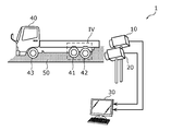
- FIG. 1A is a diagram showing a schematic configuration of an axle number measuring system according to the first embodiment.
- FIG. 1B is a diagram showing an installation example of the image pickup apparatus according to the first embodiment.
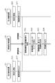
- FIG. 2 is a block diagram showing a functional configuration of the axle number measurement system according to the first embodiment.
- FIG. 3 is a sequence diagram showing the operation of the axle number measurement system according to the first embodiment.
- FIG. 4 is a diagram showing an example of a captured image according to the first embodiment.
- FIG. 5 is a diagram showing an example of a distance image according to the first embodiment.
- FIG. 6 is a flowchart showing the operation of the axle number measuring device according to the first embodiment.
- FIG. 7 is a diagram for explaining whether or not the tire according to the first embodiment is in contact with the road.
- FIG. 1A is a diagram showing a schematic configuration of an axle number measuring system according to the first embodiment.
- FIG. 1B is a diagram showing an installation example of the image pickup apparatus according to the first embodiment.
- FIG. 8 is a block diagram showing a functional configuration of the axle number measurement system according to the modified example of the first embodiment.
- FIG. 9 is a flowchart showing the operation of the axle number measuring device according to the modified example of the first embodiment.
- FIG. 10 is a block diagram showing a functional configuration of the axle number measurement system according to the second embodiment.
- FIG. 11 is a flowchart showing the operation of the axle number measuring device according to the second embodiment.
- a camera that captures an image for measuring the number of axles of a vehicle is installed, for example, near a tollhouse on a highway.
- road lights are installed near the tollhouse, and the road is illuminated to some extent.
- the camera shoots a vehicle at night in such a situation, the amount of light near the road is low, so that the captured image has a high noise ratio.
- it is difficult to accurately determine whether or not the tire is in contact with the ground.
- the exposure time becomes long.
- the exposure time at night is longer than the exposure time during the day.
- the obtained image becomes a blurred image in which the vehicle trails.
- the image will be blurred as if the tire had a tail.
- the blurred image is an example of an image containing noise.
- the axle number measuring device is an axle number measuring device that measures the number of axles of a vehicle traveling on a road, and includes a first acquisition unit that acquires a first captured image including the tires of the vehicle. , A detection unit that detects the tire from the first captured image, a plurality of first distances from a predetermined position to the tire, and a position outside the tire in the first captured image from the predetermined position.
- the first of the plurality of tires is arranged at a position from the tire to the outside of the tire and a second acquisition unit for acquiring a distance image including a plurality of second distances to the road below the tire.
- a measuring unit for measuring the number of axles supporting the tire in contact with the road is provided based on the continuity of the distance and the plurality of second distances.
- the axle number measuring device can measure the number of axles supporting the ground tire using the distance image, so that in an environment where noise in the first captured image increases, such as at night.
- the measuring unit can acquire the position of the tire in the distance image from the position of the tire in the first captured image.
- the measuring unit further determines whether the tire is in contact with the road from the first captured image.
- the number of axles is measured based on the specific result.
- external light may be incident on the image pickup device that measures the distance for generating a distance image.
- the generated distance image becomes an image containing noise due to external light. Therefore, when the number of axles is measured using a distance image including noise due to external light, the number of axles of the ground tire cannot be accurately measured.
- the axle number measuring device measures the number of axles of the ground tire by using the first captured image which is less affected by the noise without using the distance image including the noise due to the external light. Even in an environment with a brightness equal to or higher than a predetermined value, the number of axles of the ground tire can be accurately measured.
- the first captured image is captured in an environment having a brightness equal to or higher than a predetermined value such as in the daytime, the influence of noise due to the dark subject becomes small. That is, the number of axles of the ground tire can be measured more accurately from the first captured image captured in an environment having a brightness equal to or higher than a predetermined value.
- the measuring unit measures the continuity of the tire based on the amount of change from the first distance to the second distance.
- the axle number measuring device is said to have continuity between the first distance and the second distance when the amount of change from the first distance to the second distance is equal to or less than a predetermined value. Since it can be measured and measured as an axle that supports the tires in contact with the road, the number of axles can be measured more accurately.
- the tire when the tire is changed from the first distance to the second distance, if the second distance is larger than the first distance by a predetermined amount, the tire comes into contact with the road. Identify that you have not.
- the measuring unit can identify whether or not the tire is in contact with the road using a predetermined amount.
- the measuring unit can easily and accurately identify whether or not the tire is in contact with the road.
- the distance image includes the first distance and the second distance measured by the TOF (Time Of Flight) method.
- the axle number measuring device can acquire an accurate distance image even in an environment where noise in the image increases, such as at night.
- the second acquisition unit acquires a second captured image including the tire captured from a viewpoint different from the first captured image, and is based on the first captured image and the second captured image. To generate the distance image.
- the axle number measuring device can acquire a distance image (for example, a distance image including a first distance and a second distance) by using two captured images. Further, the distance image can be generated by using, for example, an existing imaging device without newly installing a TOF camera or the like to generate the distance image.
- a distance image for example, a distance image including a first distance and a second distance
- the distance image can be generated by using, for example, an existing imaging device without newly installing a TOF camera or the like to generate the distance image.
- the axle number measuring device is an axle number measuring device that measures the number of axles of a vehicle traveling on a road, and is a first acquisition that acquires a first captured image including a tire of the vehicle.
- the detection unit that detects the tire from the first captured image, and the first captured image are images captured in an environment having a brightness equal to or higher than a predetermined value, the tire is obtained from the first captured image. Whether or not it is in contact with the road is specified, and the number of axles is measured based on the specific result.
- the first captured image captured in an environment with a brightness equal to or higher than a predetermined value is not easily affected by noise due to the dark subject. That is, the number of axles of the ground tire can be accurately measured from the first captured image captured in an environment having a brightness equal to or higher than a predetermined value.
- a distance image acquired in an environment having a brightness equal to or higher than a predetermined value is an image including noise due to external light. Therefore, when the number of axles is measured using a distance image including noise due to external light, the number of axles of the ground tire cannot be accurately measured.
- grounding is performed as compared with the case where a distance image acquired in an environment having a brightness equal to or higher than a predetermined value is used. It is possible to accurately measure the number of axles of a tire.
- the axle number measuring system includes the axle number measuring device described above, the first imaging device that captures the first captured image, and imaging for generating the distance image. It is provided with a second imaging device for performing.
- the number of axles of the ground tire can be measured by using the first image captured image and the distance image from the first image pickup device and the second image pickup device provided in the own system without acquiring the captured image or the like from the outside. it can.
- the method for measuring the number of axles is a method for measuring the number of axles of a vehicle traveling on a road, and includes the first acquisition step of acquiring an image taken including the tires of the vehicle.
- a second acquisition step of acquiring a distance image including a plurality of second distances to the road below the tire, and the plurality of first distances and the plurality of tires arranged at positions from the tire to the outside of the tire. Includes a measurement step of measuring the number of axles supporting the tire in contact with the road based on continuity with the second distance.
- each figure is a schematic diagram and is not necessarily exactly illustrated. Further, in each figure, substantially the same configuration may be designated by the same reference numerals, and duplicate description may be omitted or simplified.
- the image is, for example, a still image, but may be a moving image. Further, the image is, for example, a color image, but may be a monochrome image.
- the axle is lifted by using an image captured by an imaging device for capturing a subject and a distance image obtained by another imaging device capturing the subject.
- An axle number measuring device for measuring the number of axles of ground tires in a vehicle that has been uploaded will be described.
- FIG. 1A is a schematic view showing the configuration of the axle number measuring system 1 according to the present embodiment.
- FIG. 1B is a diagram showing an installation example of an imaging device according to the present embodiment.
- FIG. 2 is a block diagram showing a functional configuration of the axle number measurement system 1 according to the present embodiment.
- the axle number measuring system 1 includes a first imaging device 10, a second imaging device 20, and an axle number measuring device 30.
- the axle number measurement system 1 is an information processing system for measuring the number of axles of a ground tire in a vehicle 40 traveling on a road 50.
- the first image pickup device 10 and the second image pickup device 20 take an image of the vehicle 40 traveling on the road 50 from the side of the vehicle 40.
- the first imaging device 10 and the second imaging device 20 are installed on the road 50 (or the side of the road) so as to image the same area, for example.
- the first imaging device 10 and the second imaging device 20 may image the vehicle 40 at the same angle of view, for example. Further, the first imaging device 10 and the second imaging device 20 may be installed close to each other, for example.
- the first imaging device 10 and the second imaging device 20 are installed adjacent to each other along the road 50 on which the vehicle 40 travels.
- the first imaging device 10 has an image sensor and captures one or more captured images (see captured image P1 shown in FIG. 4 described later) including one or more tires of a vehicle 40 traveling on a road 50.
- the image sensor has, for example, an image sensor.
- a solid-state image sensor such as a CMOS (Complementary Metal Oxide Semiconductor) image sensor or a CCD (Charge Coupled Device) image sensor can be used.
- the first imaging device 10 is realized by, for example, a camera (for example, a visible light camera), but is not limited thereto.
- the captured image is, for example, a visible light image.
- the second imaging device 20 has a distance sensor and acquires one or more distance images (see the distance image P2 shown in FIG. 5 described later) including one or more tires of the vehicle 40 traveling on the road 50.
- the distance sensor has a light emitting element and a light receiving element. That is, the second imaging device 20 is an imaging device different from the first imaging device 10.
- the distance sensor measures the time from when the light from the light emitting element is irradiated until when the light receiving element receives the light, and acquires a distance image by the TOF (Time Of Flight) method which converts the time difference into the distance.
- TOF Time Of Flight
- the method of acquiring the distance image is not limited to this.
- a PSD Position Sensitive Detector
- a distance image may be acquired by a triangular distance measuring method in which a change in the imaging position of the light receiving element due to a change in distance is converted into a distance.
- the second image pickup apparatus 20 is realized by, for example, a TOF type distance image camera, but is not limited thereto.
- the distance image includes a first distance between the second image pickup device 20 and one or more tires of the vehicle 40, and a second distance between the second image pickup device 20 and the road 50. It can be said that the second distance is the distance from the second imaging device 20 to the road surface. Further, one or more tires of the vehicle 40 imaged by the second imaging device 20 include one or more tires imaged by the first imaging device 10.
- each of the first imaging device 10 and the second imaging device 20 may have, for example, a timer device for measuring the current date and time.
- the timer device is realized by, for example, a real-time clock.
- the information obtained by the first imaging device 10 and the second imaging device 20 are different from each other.
- FIG. 1B is a view of the vehicle 40 as viewed from the front side. Although only the second imaging device 20 is shown in FIG. 1B, the same can be said for the first imaging device 10.
- the second imaging device 20 is installed at a predetermined angle ⁇ with respect to the road 50.
- the angle ⁇ is, for example, an angle at which the axle number measuring device 30 can acquire a distance image capable of measuring the number of axles of the ground tire.
- the angle ⁇ is, for example, an angle formed by the road 50 and the optical axis J of the second imaging device 20 when viewed from the front of the vehicle 40.
- the second imaging device 20 is fixed in such a posture that, for example, the optical axis J passes near the ground contact point or the installation point between the ground contact tire and the road 50.
- the angle ⁇ is, for example, 60 ° or less, more preferably 45 ° or less, and even more preferably 30 ° or less.
- the second imaging device 20 may be installed on the road 50 (on the road surface) where the angle ⁇ is 0 °, but from the viewpoint of suppressing the adhesion of objects such as sand and dust, the second imaging device 20 may be installed on the road 50.
- the predetermined value may be, for example, 50 cm, more preferably 100 cm, and even more preferably 150 cm.
- angle ⁇ of the first imaging device 10 and the angle ⁇ of the second imaging device 20 may be different from each other.
- the axle number measuring device 30 has the presence or absence of ground contact of the tires of the vehicle 40 based on the image captured by the first imaging device 10 and the distance image from the second imaging device 20. It is an information processing device that determines the number of axles of the ground tire, measures the number of axles, and outputs the measurement result.
- the axle number measuring device 30 includes a first communication unit 31, a second communication unit 32, a detection unit 33, and a measurement unit 34.
- the axle number measuring device 30 is realized, for example, by executing a program stored in the memory in a computer (not shown) including a microprocessor (not shown) and a memory (not shown).
- the first communication unit 31 is a communication circuit (in other words, a communication module) for the axle number measuring device 30 to communicate with the first imaging device 10.
- the first communication unit 31 acquires an captured image from, for example, the first imaging device 10.
- the first communication unit 31 is an example of the first acquisition unit.
- the second communication unit 32 is a communication circuit (in other words, a communication module) for the axle number measuring device 30 to communicate with the second imaging device 20.
- the second communication unit 32 acquires a distance image from, for example, the second imaging device 20.
- the second communication unit 32 is an example of the second acquisition unit.
- Each of the first communication unit 31 and the second communication unit 32 is, for example, a wireless communication circuit for performing wireless communication, but may be a wired communication circuit for performing wired communication.
- the communication standard of the communication performed by the first communication unit 31 and the second communication unit 32 is not particularly limited. Further, the first communication unit 31 and the second communication unit 32 may be configured by one communication circuit.
- the detection unit 33 detects one or more tires from one or more captured images acquired from the first imaging device 10.
- the method for detecting the tire in the detection unit 33 is not particularly limited, and the prior art may be used.
- the detection unit 33 may detect a tire by, for example, performing machine learning related to tire recognition in advance. That is, the detection unit 33 may detect the tire by using the trained model regarding the tire recognition. Further, the detection unit 33 may detect the tire by using, for example, a template matching method.
- the detection unit 33 can acquire information indicating the respective positions of one or more tires.
- the information indicating the position of the tire may be a position on the captured image (for example, a pixel position). Further, the position of the tire may be the center position of the tire or the region where the tire exists.
- the detection unit 33 may further detect the wheels in each of the detected one or more tires.
- the method for detecting the wheel in the detection unit 33 is not particularly limited as in the method for detecting the tire, and the prior art may be used.
- the detection unit 33 can acquire information indicating the position of each of the one or more wheels by detecting one or more wheels, for example.
- the information indicating the position of the wheel may be the position on the captured image. Further, the position of the wheel may be the center position of the wheel or the area where the wheel exists.
- the measuring unit 34 is a tire in contact with the road 50 in the vehicle 40 based on the position information indicating the position of each of the one or more tires detected by the detecting unit 33 and the distance image from the second imaging device 20. Measure the number of axles of the axle that supports (ground tire). The measuring unit 34 determines whether or not the tire is in contact with the road 50 based on the position information and the distance image, and measures the number of axles of the tire determined to be in contact.
- the measuring unit 34 is, for example, a plurality of first distances to the position of the tire in the distance image and a plurality of second distances to the road 50 below the tire, which are positions outside the tire in the captured image P1.
- the measuring unit 34 determines whether or not the tire is in contact with the road 50 based on the amount of change from the first distance to the second distance, and measures the number of axles of the tire determined to be in contact. To do.
- FIG. 3 is a sequence diagram showing the operation of the axle number measuring system 1 according to the present embodiment.
- the first imaging device 10 images the vehicle 40 (S11) and outputs the captured image obtained by the imaging to the axle number measuring device 30 (S12). Further, the second imaging device 20 images the vehicle 40 (S21), and outputs the distance image obtained by the imaging to the axle number measuring device 30 (S22).
- step S21 the light emitting element of the second imaging device 20 irradiates the pulsed light, and the light receiving element of the second imaging device 20 receives the reflected light reflected by the object.
- the calculation unit of the second image pickup apparatus 20 executes a calculation of converting the time difference from irradiating the pulsed light to receiving the reflected light into a distance. As a result, a distance image is obtained.
- the region imaged in step S11 and the region imaged in step S21 are regions including one or more tires of the vehicle 40, and may be, for example, the same region.
- the region imaged in step S11 and the region imaged in step S21 may be the broken line region IV shown in FIG. 1A, respectively.
- the captured image output in step S12 and the distance image output in step S22 may be images captured at the same time.
- the images captured at the same time may be images obtained by the imaging timings of the first imaging device 10 and the second imaging device 20 being synchronized and the imaging operations being executed at the same timing. ..
- the first imaging device 10 and the second imaging device 20 are constantly performing imaging, and the image captured at the same time may be an image obtained by cutting out the image captured at the same time. Good.
- the axle number measuring device 30 acquires an captured image from the first imaging device 10 and acquires a distance image from the second imaging device 20 (S31).
- the first communication unit 31 of the axle number measuring device 30 acquires an captured image from the first imaging device 10
- the second communication unit 32 of the axle number measuring device 30 is the second imaging device 20. Get a distance image from.
- the acquisition timings of the captured image and the distance image may be the same or different.
- Step S31 is an example of the first acquisition step and the second acquisition step.
- FIG. 4 is a diagram showing an example of the captured image P1 according to the present embodiment.
- FIG. 5 is a diagram showing an example of the distance image P2 according to the present embodiment.
- each of FIG. 4 and FIG. 5 is an image obtained by capturing the broken line region IV shown in FIG. 1A.
- the distance from the second imaging device 20 is shown in gray scale, and the closer it is, the whiter it is, and the farther it is, the blacker it is.
- the axle number measuring device 30 acquires the captured image P1 and the distance image P2 including the rear wheel tires 41 and 42 of the rear axle of the vehicle 40.
- the captured image P1 is an example of the first captured image.
- the distance image P2 is formed by a distance measured from a predetermined position.
- the predetermined position is, for example, the position where the second imaging device 20 is installed, but is not limited to this.
- the predetermined position may be, for example, a position where the first imaging device 10 is installed. In this case, the distance image captured by the second imaging device 20 is corrected for the distance according to the difference in the installation position between the first imaging device 10 and the second imaging device 20.
- step S31 the first communication unit 31 captures the captured image P1 including the front wheel tires 43 of the front axle of the vehicle 40 and the rear wheel tires 41 and 42 of the rear axle of the vehicle 40. It may be obtained from. Further, in step S31, the second communication unit 32 captures the distance image P2 including the front wheel tire 43 of the front axle of the vehicle 40 and the rear wheel tires 41 and 42 of the rear axle of the vehicle 40 in the second imaging device 20. It may be obtained from.
- the first communication unit 31 outputs the acquired captured image P1 to the detection unit 33. Further, the second communication unit 32 outputs the acquired distance image P2 to the measurement unit 34.
- the detection unit 33 detects one or more tires from the acquired captured image P1 (S32).
- the detection unit 33 detects the rear wheel tires 41 and 42.
- the detection unit 33 detects, for example, a tire region R1 indicating the position of the rear wheel tire 41 and a tire region R2 indicating the position of the rear wheel tire 42. Further, the detection unit 33 may detect the position of each wheel of one or more tires from the acquired captured image P1.
- the rear wheel tires 41 and 42 are examples of one or more tires.
- Step S32 is an example of a detection step.
- the tire can be detected even in the captured image P1 captured in an environment where the influence of noise such as at night is large.
- the first imaging device 10 can capture an image P1 having an image quality that allows the tire to be detected.
- the detection unit 33 outputs position information indicating the position of one or more detected tires to the measurement unit 34.
- the detection unit 33 outputs information indicating the tire regions R1 and R2 to the measurement unit 34 as position information.
- the measuring unit 34 measures the number of axles based on the distance image P2 (S33). Specifically, the measuring unit 34 identifies the positions of one or more tires in the distance image P2 based on the position information acquired from the detecting unit 33, and in each of the specified one or more tires, the road 50 It is determined whether or not the tire is in contact with the tire, and the number of axles of the ground tire is measured based on the determination result. The method of determining whether or not the tire and the road 50 are in contact with each other will be described later. Step S33 is an example of a measurement step.
- the measuring unit 34 outputs the number of axles measured in step S33 (S34).
- the measuring unit 34 may output the number of axles to an external device, or when the number of axles measuring device 30 has a display unit such as a display, the number of axles may be displayed on the display unit.
- the number of axles measured by the measuring unit 34 is an example of the measurement result.
- FIG. 6 is a flowchart showing the operation of the axle number measuring device 30 according to the present embodiment.
- the axle number measuring device 30 acquires the captured image P1 and the distance image P2 (S101).
- the captured image P1 is output to the detection unit 33. Further, the distance image P2 is output to the measurement unit 34.
- Step S101 corresponds to step S31 shown in FIG.
- the detection unit 33 detects one or more tires from the captured image P1 (S102).
- the detection unit 33 specifies, for example, the positions of one or more tires from the captured image P1.
- the detection unit 33 outputs position information indicating the detected positions of one or more tires to the measurement unit 34.
- Step S102 corresponds to step S32 shown in FIG.
- the measuring unit 34 identifies the positions of one or more tires in the distance image P2 based on the position information acquired from the detecting unit 33 (S103).
- the captured image P1 and the distance image P2 are images obtained by capturing the same region (for example, the broken line region IV). Therefore, the position of the tire in the captured image P1 and the position of the tire in the distance image P2 are equal. Therefore, for example, as shown in FIG. 5, the measuring unit 34 superimposes the tire regions R1 and R2 included in the position information on the distance image P2.
- the measuring unit 34 identifies the positions of one or more tires in the distance image P2 based on the position information acquired from the detecting unit 33.
- the captured image P1 is used to identify the position of one or more tires in the distance image P2.
- the captured image P1 is not used for determining whether or not the tire is in contact with the road 50.
- the measuring unit 34 may add a predetermined correction to the position information and specify the position of one or more tires in the distance image P2 based on the corrected position information.
- Adding a predetermined correction includes, for example, correcting at least one of the position and size of the tire region R1 in the captured image P1.
- the measuring unit 34 corresponds the tire regions R1 and R2 detected in the captured image P1 to the tire regions R1 and R2, for example, according to the difference in the installation state of the first imaging device 10 and the second imaging device 20.
- the process of converting to the region on the distance image P2 and superimposing it may be performed.
- the installation state includes the position where the first imaging device 10 and the second imaging device 20 are installed, the direction of the optical axis J, and the like.
- the measuring unit 34 determines whether or not the tire is in contact with the road 50 based on the distance image P2 in which the positions of one or more tires are specified (S104). In other words, the measuring unit 34 measures the number of axles of the tire in contact with the road 50 in the vehicle 40 based on the continuity of the distance values from the tire to the road 50 in the distance image P2. Specifically, the measuring unit 34 is the first distance from the second imaging device 20 to the tire in the distance image P2, and the position outside the tire in the captured image P1 from the second imaging device 20. The number of axles of the tire in contact with the road 50 in the vehicle 40 is measured based on the continuity with the second distance to the road 50 below the tire.
- the measuring unit 34 supports a tire in contact with the road 50, for example, based on the continuity of the plurality of first distances and the plurality of second distances arranged at a position from the tire to the outside of the tire. Measure the number of axles.
- the measuring unit 34 is, for example, a straight line passing through the center of the tire and on a straight line extending downward in the vertical direction when the vehicle 40 is viewed from the side, and the second imaging device on the road 50 from the tire. Based on the continuity of the distance to 20, the contact of the tires of the vehicle 40 with the road 50 is determined, and the number of axles of the tires in contact with the road 50 in the vehicle 40 is measured.
- the center of the tire may be, for example, the center of the wheel.
- the measurement unit 34 determines whether or not the rear wheel tire 41 is in contact with the road 50 based on the continuity of the distance within the measurement area R3.
- the measurement region R3 includes, for example, a part of the rear wheel tire 41 and a region below the tire region R1.
- the measurement area R3 is an area including the center of the rear tire 41 and the road 50 below the center of the rear tire 41.
- the measurement unit 34 determines whether or not the rear wheel tire 42 is in contact with the road 50 based on the continuity of the distance within the measurement area R4.
- the measurement region R4 includes, for example, a part of the rear wheel tire 42 and a region below the tire region R2.
- the measurement area R4 is an area including the center of the rear tire 42 and the road 50 below the center of the rear tire 42.
- FIG. 7 is a diagram for explaining whether or not the tire and the road 50 according to the present embodiment are in contact with each other.
- FIG. 7A is a diagram for explaining the determination of the continuity of the distance in the measurement area R3. That is, FIG. 7A shows the measurement result of the distance for determining whether or not the rear wheel tire 41 is in contact with the road 50.
- FIG. 7B is a diagram for explaining the determination of the continuity of the distance in the measurement area R4. That is, FIG. 7B shows the measurement result of the distance for determining whether or not the rear wheel tire 42 is in contact with the road 50.
- FIGS. 7A and 7B are measurement results obtained by measuring the distance from the wheel to the second imaging device 20 on the road 50, but at least the distance between the tire and the second imaging device 20. It is sufficient to include the measurement result of measuring the distance between the road 50 and the second imaging device 20 at a position immediately below the tire.
- the traveling direction of the vehicle 40 is the direction perpendicular to the paper surface of FIG. 7.
- the distances in FIGS. 7A and 7B are distances when the vehicle 40 is viewed from the side. “Distance: small” means that the distance to the second imaging device 20 is short.
- the distances are not continuous at the boundary between the rear tire 41 and the road 50. Specifically, in the two-dot chain line region shown in FIG. 7A, the distances are not continuous.
- the amount of change d1 in the distance is generated between the lowest point of the rear tire 41 and the position directly below the rear tire 41 on the distance image P2. This is because the rear wheel tire 41 is floating from the road 50, and in the distance image P2, the position directly below the rear wheel tire 41 is the road 50 farther than the rear wheel tire 41.
- the broken line at the boundary between the tire and the road 50 in FIG. 7A is the broken line on the lower side (road 50 side) of the broken lines extending in the traveling direction of the vehicle 40 constituting the tire region R1 in FIG. Indicates the position.
- the position directly below the rear wheel tire 41 is an example of a position adjacent to the tire in the road 50 direction. In the present embodiment, the position directly below the rear wheel tire 41 is, for example, the road 50.
- the position directly below the rear wheel tire 41 in the distance image P2 is a predetermined number of pixels below the pixel corresponding to the lowest point of the rear wheel tire 41 (hereinafter, also referred to as the lowest point pixel). It may be the position of a pixel (hereinafter, also referred to as a pixel directly below).
- the predetermined number of pixels may be any value as long as it can be determined by the lift axle mechanism that the tire is lifted to the extent that it does not come into contact with the road 50.
- the predetermined number of pixels may be 1, for example. That is, the immediate pixel may be a pixel adjacent to the lowest point pixel. Further, the predetermined number of pixels may be, for example, the number of pixels corresponding to a predetermined distance (for example, several centimeters) in real space conversion from the lowest point pixel.
- the measurement unit 34 determines that the rear wheel tire 41 is not in contact with the road 50. That is, the measuring unit 34 determines that the rear tire 41 has been lifted up.
- the predetermined amount may be any value as long as it can be determined whether or not the rear wheel tires 41 are in contact with each other.
- the predetermined amount is appropriately determined, for example, by the angle ⁇ in the second imaging device 20 and the like.
- the predetermined amount may be larger than, for example, the dent amount d2, which is the difference between the first distance to the rear wheel tire 41 and the third distance to the wheel.
- the predetermined amount may be, for example, larger than the dent amount d2 and smaller than the change amount d1.
- the measurement unit 34 determines that the rear wheel tire 41 is not in contact with the road 50 because the dent amount d2 is larger than the predetermined value. It is possible to prevent erroneous determination due to the above.
- the distance changes gently at the boundary between the rear tire 42 and the road 50. That is, the distance is continuous at the boundary between the rear tire 42 and the road 50.
- the lowest point of the rear wheel tire 42 and the position directly below the rear wheel tire 42 on the distance image P2 have the same distance. This is because the rear wheel tire 42 is in contact with the road 50, and in the distance image P2, the road 50 directly below the rear wheel tire 42 is at the same distance as the rear wheel tire 42.
- the broken line at the boundary between the tire and the road 50 in FIG. 7B is the broken line on the lower side (road 50 side) of the broken lines extending in the traveling direction of the vehicle 40 constituting the tire region R2 in FIG. Indicates the position.
- the position directly below the rear wheel tire 42 is an example of a position adjacent to the tire in the road direction. In the present embodiment, the position directly below the rear wheel tire 42 is, for example, the road 50.
- the measuring unit 34 determines that the rear wheel tire 42 is in contact with the road 50. That is, the measuring unit 34 determines that the rear tire 42 is not lifted up. Further, the measuring unit 34 may determine that the rear wheel tire 42 is in contact with the road 50 when the change amount d1 shown in FIG. 7A is not more than a predetermined amount.
- the measuring unit 34 measures the continuity of the distance in the tire based on the amount of change d1 from the first distance to the second distance. That is, the measuring unit 34 determines the continuity of the distance in the tire based on the amount of change d1 from the first distance to the second distance.
- the measuring unit 34 is, for example, a first distance to the lowest point of the rear wheel tire 42 and a position outside the tire region R2, as shown in FIG. 7 (b).
- the lowest point and the second distance to the adjacent position match, or the amount of change between the two distances is equal to or less than a predetermined amount
- the rear wheel tire 42 is in contact with the road 50. (Yes in S104), and the axle of the rear tire 42 is counted as the number of axles of the ground tire (S105).
- the measuring unit 34 adds 1 to the number of axles of the ground tire.
- the measuring unit 34 is, for example, as shown in FIG. 7A, a first distance to the lowest point of the rear wheel tire 41, a position outside the tire region R1, and the lowest point.
- the amount of change d1 from the second distance to the adjacent position is larger than the predetermined amount, it is determined that the tire is not in contact with the road 50 (No in S104), and the process proceeds to step S106. That is, in the tire, when the second distance is larger than the first distance by a predetermined amount at the time of the change from the first distance to the second distance in the distance image P2, the tire is not in contact with the road 50. To identify.
- the measuring unit 34 is not limited to making the above determination using the first distance to the lowest point of the tire.
- the measuring unit 34 may make the above determination using the first distance to the tire.
- the first distance may be, for example, the distance to the outer circumference of the tire, or the distance from the outer circumference of the tire to a position inside a predetermined distance.
- the measuring unit 34 has a first distance to a position other than the lowest point of the tire and a position outside the rear wheel tire 41 to a position adjacent to the lowest point of the rear wheel tire 41.
- the amount of change d1 with respect to the two distances is not more than a predetermined amount, it is determined that the rear wheel tire 41 is in contact with the road 50 (Yes in S104). This is also included in determining the tire in contact with the road 50 based on the continuity of the first distance and the second distance.
- the measurement unit 34 confirms whether or not all the tires have been determined when the process of step S105 is executed or when No is determined in step S104 (S106).
- the measuring unit 34 determines, for example, whether or not the determination in step S104 has been executed for each of the one or more tires detected in step S102.
- the measurement unit 34 determines all the tires (Yes in S106)
- the measurement unit 34 outputs the number of axles (S107) and ends the process. If the measurement unit 34 has not determined all the tires (No in S106), the measurement unit 34 returns to step S104 and executes the processes after step S104 for the remaining tires.
- steps S103 to S106 correspond to steps S33 shown in FIG. Further, step S107 corresponds to step S34 shown in FIG.
- Step S107 corresponds to step S34 shown in FIG.
- the axle number measuring device 30 has the acquisition unit (for example, the first communication unit 31 and the second communication unit 32) for acquiring the captured image P1 and the distance image P2, and the distance image P2.
- the detection unit 33 that detects one or more tires based on the captured image P1 and the continuity of the first distance and the second distance in the distance image P2 are used.
- It has a measuring unit 34 for measuring the number of axles of the ground tire. At the boundary (contact point) between the ground tire and the road 50, the measuring unit 34 has a continuous distance on the distance image P2, and the lifted tire and the road 50 are on the distance image P2. Utilizing the fact that the distances are not continuous, the contact between the tire and the road 50 is determined, and the number of axles of the grounded tire is measured from the continuity of the distance.
- the axle number measuring device 30 performs the above measurement using the distance image P2 having less noise in an environment where the noise in the captured image P1 increases such as at night. Therefore, the axle number measuring device 30 can accurately measure the number of axles of the ground tire even in an environment where noise in the captured image P1 increases, such as at night.
- FIG. 8 is a block diagram showing a functional configuration of the axle number measuring system 1a according to this modification.
- the same configuration as that of the axle number measurement system 1 according to the first embodiment is designated by the same reference numerals as those of the first embodiment, and the description thereof will be omitted or simplified.
- the axle number measuring system 1a includes a first imaging device 10, a second imaging device 20, and an axle number measuring device 30a.
- the axle number measuring device 30a has a determination unit 35 in addition to the axle number measuring device 30 according to the first embodiment.
- the first imaging device 10 outputs exposure time information indicating the exposure time to the axle number measuring device 30a.
- the timing at which the first imaging device 10 outputs the exposure time information to the axle number measuring device 30a is not particularly limited.
- the first image pickup apparatus 10 may, for example, include the exposure time information indicating the exposure time when the captured image P1 is imaged in the captured image P1 and output it to the axle number measuring device 30a. Further, the first imaging device 10 may output exposure time information to the axle number measuring device 30a at predetermined time intervals, for example. Further, the first imaging device 10 may output the exposure time information in the imaging to the axle number measuring device 30a before starting the imaging. Further, when the first imaging device 10 acquires, for example, information indicating that the vehicle 40 travels in front of the second imaging device 20, the exposure time before the vehicle 40 travels in front of the second imaging device 20. The information may be output to the axle number measuring device 30a.
- the first communication unit 31 is a communication circuit (in other words, a communication module) for the axle number measuring device 30a to communicate with the first imaging device 10.
- the first communication unit 31 acquires, for example, the captured image P1 and the exposure time information from the first imaging device 10.
- the first communication unit 31 is an example of the first acquisition unit.
- the determination unit 35 determines whether or not the captured image P1 acquired from the first imaging device 10 is an image captured in an environment having a brightness equal to or higher than a predetermined value.
- the determination unit 35 is an image in which the captured image P1 is captured in an environment having a brightness equal to or higher than a predetermined value based on the exposure time when the captured image P1 is captured by the first imaging device 10. It is determined whether or not it is. For example, when the exposure time when the captured image P1 is captured is a predetermined time or less, the determination unit 35 determines that the captured image P1 is an image captured in an environment having a brightness equal to or higher than a predetermined time.
- the predetermined time is such that noise due to external light does not affect the detection of the grounded tire in the imaging by the second imaging device 20.
- An environment having a brightness equal to or higher than a predetermined value is, for example, an environment in which the road 50 is irradiated with external light such as sunlight, for example, a daytime environment.
- the environment having a brightness equal to or higher than a predetermined value may be, for example, an environment in the imaging region of the first imaging device 10 and the second imaging device 20. It can also be said that the determination unit 35 determines whether or not the amount of external light applied to the road 50 is equal to or greater than a predetermined value.
- the imaging region is, for example, the broken line region IV shown in FIGS. 4 and 5.
- the outside light may be reflected by the road 50 and enter the second imaging device 20.
- the incident external light becomes noise in the distance image P2. That is, it is difficult for the second imaging device 20 to systematically measure the distance in an environment having a brightness equal to or higher than a predetermined value.
- the measurement unit 34 determines that the captured image P1 is an image captured in an environment having a brightness equal to or higher than a predetermined value by the determination unit 35. Of the captured image P1 and the distance image P2, only the captured image P1 is used to measure the number of axles of the ground tire.
- the external light is light other than the light emitted by the second image pickup apparatus 20, and is, for example, sunlight or illumination light.
- FIG. 9 is a flowchart showing the operation of the axle number measuring device 30a according to this modification.
- the same operations as those in the first embodiment are designated by the same reference numerals as those in the first embodiment, and the description thereof will be omitted or simplified. Further, in the following, the case where the first imaging device 10 outputs the exposure time information in the imaging to the axle number measuring device 30a before starting the imaging will be described.
- the first communication unit 31 of the axle number measuring device 30a acquires the exposure time information in the captured image P1 from the first imaging device 10 (S201).
- the first communication unit 31 may periodically acquire the exposure time information, and when it is detected in advance that the vehicle 40 passes, the vehicle 40 enters the imaging region of the second imaging device 20.
- the exposure time information may be acquired before.
- the first communication unit 31 outputs the exposure time information to the determination unit 35.
- the determination unit 35 determines whether or not the exposure time indicated by the exposure time information is equal to or less than a predetermined time (S202). Determining whether or not the exposure time indicated by the exposure time information is equal to or less than a predetermined time is an example of determining whether or not the captured image P1 is an image captured in an environment having a predetermined brightness or more. Is. For example, the determination unit 35 determines whether or not the amount of outside light near the road 50 is equal to or greater than a predetermined value.
- the determination unit 35 determines that the captured image P1 is an image captured in an environment having a brightness equal to or higher than the predetermined time (Yes in S202), and steps. Proceed to S203. Further, the determination unit 35 determines that the captured image P1 is not an image captured in an environment having a brightness equal to or higher than a predetermined time when the exposure time indicated by the exposure time information is longer than the predetermined time (No in S202). The process proceeds to step S101.
- the processing after step S101 is the same as that in FIG. 6 of the first embodiment, and the description thereof will be omitted.
- the determination unit 35 determines whether or not the captured image P1 is an image captured in an environment having a brightness equal to or higher than a predetermined value based on the exposure time information, but the present invention is not limited to this.
- the determination unit 35 may make a determination in step S202 based on, for example, the captured image P1 acquired from the first imaging device 10.
- the determination unit 35 may make a determination in step S202, for example, based on the pixel value for each pixel included in the captured image P1. For example, when the value based on the pixel value for each pixel is a predetermined value or more, the determination unit 35 may determine that the captured image P1 is an image captured in an environment having a brightness equal to or higher than a predetermined value. ..
- the first imaging device 10 outputs the captured image P1 to the axle number measuring device 30a.
- the first communication unit 31 outputs the acquired captured image P1 to both the measurement unit 34 and the determination unit 35.
- the value based on the pixel value for each pixel may be, for example, any of the maximum value, the minimum value, the average value, the median value, the mode value, etc. of the pixel value for each pixel, and is predetermined. It may be a pixel value of one or more pixels of, or it may be a value obtained by performing a predetermined calculation on the pixel value.
- the captured image P1 used for determining step S202 may be, for example, the captured image P1 acquired from the first imaging device 10 last time.
- the determination unit 35 acquires, for example, the illuminance near the road 50 (for example, the illuminance in the imaging region of the second imaging device 20) from an external illuminance sensor, and determines the determination in step S202 based on the acquired illuminance. You may go. Further, the determination unit 35 acquires, for example, the weather information of the area where the second imaging device 20 is installed from the weather information server that manages the weather information, and determines the determination in step S202 based on the acquired weather information. You may go. Meteorological information includes, for example, temperature, rainfall, cloud cover, solar radiation, weather, and weather.
- the determination unit 35 determines that the captured image P1 is an image captured in an environment having a brightness equal to or higher than the predetermined value, for example, when the amount of solar radiation is equal to or higher than a predetermined value or the weather is fine. You may.
- the illuminance and weather information are acquired, for example, via at least one of the first communication unit 31 and the second communication unit 32. Further, the determination unit 35 may acquire the current time and make a determination in step S202 based on the acquired current time.
- the determination unit 35 may determine that the captured image P1 is an image captured in an environment having a brightness equal to or higher than a predetermined value, for example, when the current time is a time indicating daytime.
- the determination unit 35 may output stop information indicating that the imaging of the second imaging device 20 is stopped to the second imaging device 20 via the second communication unit 32. Good. As a result, the second imaging device 20 stops the imaging operation, so that the power consumption of the second imaging device 20 can be reduced. Further, if the determination unit 35 determines Yes in step S202, the determination unit 35 may output measurement control information indicating that the number of axles of the ground contact tire is measured based on the captured image P1 to the measurement unit 34. Thereby, in the case of Yes in step S202, when the measuring unit 34 acquires the distance image P2, it is possible to prohibit the measuring unit 34 from measuring the number of axles of the ground tire using the distance image P2. ..
- the first communication unit 31 acquires the captured image P1 from the first imaging device 10 (S203).
- the first communication unit 31 outputs the acquired captured image P1 to the detection unit 33.
- the detection unit 33 detects one or more tires from the captured image P1 (S204). For example, when the captured image P1 is an image captured in an environment having a brightness equal to or higher than a predetermined value, the detection unit 33 further determines whether or not each of the tires 1 or higher from the captured image P1 is in contact with the road 50. To identify.
- the process of step S204 is the same as that of step S102, and the description thereof will be omitted.
- the measuring unit 34 determines whether or not the tire is in contact with the road 50 based on the captured image P1 in which the positions of one or more tires are specified (S205). That is, the measurement unit 34 identifies whether or not the tire is in contact with the road 50 based on the captured image P1.
- the determination method for determining whether or not the tire is in contact with the road 50 based on the captured image P1 is not particularly limited, and the prior art may be used.
- the measuring unit 34 calculates, for example, a reference line extending in the traveling direction of the vehicle 40 from the lowest point of the rear wheel tire 42.
- the measuring unit 34 has the lowest point of the tires on the upper side of the vehicle 40 with respect to the reference line with respect to the tires other than the front tire 43 and the rear tire 42 (for example, the rear tire 41). Whether or not the tire is in contact with the road 50 is determined based on whether or not the tire is separated by a predetermined value or more.
- the measuring unit 34 may calculate, for example, a straight line connecting the lowest point of the front tire 43 and the lowest point of the rear tire 42 as the reference line.
- the above-mentioned predetermined value is any value as long as it is a value indicating that the tires other than the front wheel tire 43 and the rear wheel tire 42 are lifted by the lift axle mechanism to the extent that they do not come into contact with the road 50. It may be.
- the above predetermined value may be, for example, a predetermined number of pixels in the captured image P1 (for example, 1000 pixels), or a predetermined number of pixels in the captured image P1 corresponding to a predetermined distance (for example, 10 cm) in real space conversion. It may be.
- the measuring unit 34 may determine whether or not the tire is in contact with the road 50 depending on whether or not the tire is rotating.
- the measurement unit 34 determines whether or not the tire is rotating based on, for example, two or more captured images P1 continuously imaged, and when the tire is rotating, the tire is referred to as the road 50. It may be determined that they are in contact.
- the measuring unit 34 determines that the tire is in contact with the road 50 (Yes in S205)
- the measuring unit 34 counts the axle of the tire as the number of axles of the grounded tire (S206). That is, when the captured image P1 is an image captured in an environment having a brightness equal to or higher than a predetermined value, the measuring unit 34 measures the number of axles based on the specific result of the detecting unit 33. For example, in the case of Yes in step S205, the measuring unit 34 adds 1 to the number of axles of the ground tire. Further, when the measurement unit 34 determines that the tire is not in contact with the road 50 (No in S205), the measurement unit 34 proceeds to step S207.
- the measurement unit 34 confirms whether or not all the tires have been determined when the process of step S206 is executed or when No is determined in step S205 (S207).
- the measuring unit 34 determines, for example, whether or not the process of step S205 has been executed for each of the one or more tires detected in step S204.
- the measurement unit 34 determines all the tires (Yes in S207)
- the measurement unit 34 outputs the number of axles (S107) and ends the process. If the measurement unit 34 has not determined all the tires (No in S207), the measurement unit 34 returns to step S205 and executes the process of step S205 for the remaining tires.
- the axle number measuring device 30a has a determination unit 35 for determining whether or not the captured image P1 is an image captured in an environment having a brightness equal to or higher than a predetermined value. Then, the measurement unit 34 switches the measurement method of the number of axles according to the determination result by the determination unit 35.
- the determination unit 35 determines that the captured image P1 is an image captured in an environment having a brightness equal to or higher than a predetermined value (corresponding to Yes in S202)
- the measuring unit 34 determines that the captured image P1 is a ground contact tire based on the captured image P1.
- the number of axles is measured (S203 to S207).
- the measurement unit 34 determines based on the distance image P2. The number of axles of the ground contact tire is measured (S101 to S107).
- the axle number measuring device 30a performs the above measurement using the captured image P1 having less noise in an environment where the noise in the distance image P2 increases such as in the daytime. Therefore, the axle number measuring device 30a can accurately measure the number of axles of the ground tire even in an environment where noise in the distance image P2 increases such as in the daytime.
- step S202 when No in step S202, an example in which the number of axles is counted based on the captured image and the distance image has been described, but the present invention is not limited to this.
- the axle number measuring device 30a when the number of axles measuring device 30a is No in step S202, it is not necessary to perform the process of counting the number of axles.
- the axle number measuring device 30a may perform a process of counting the number of axles using the captured image when at least Yes in step S202.
- the axle number measuring device 30a determines whether or not the captured image is an image captured in an environment having a brightness equal to or higher than a predetermined value, and the captured image is captured in an environment having a brightness equal to or higher than a predetermined value.
- the number of axles may be measured using the captured image. In this case, the distance image is not used for measuring the number of axles.
- FIG. 10 is a block diagram showing a functional configuration of the axle number measuring system 100 according to the present embodiment.
- the same configuration as that of the axle number measurement system 1 according to the first embodiment is designated by the same reference numerals as those of the first embodiment, and the description thereof will be omitted or simplified.
- the axle number measuring system 100 includes a first imaging device 10, a second imaging device 120, and an axle number measuring device 130.
- the configuration of the second imaging device 120 is, for example, the same as that of the first imaging device 10.
- the second imaging device 120 has an image sensor and captures one or more captured images including one or more tires of a vehicle 40 traveling on a road 50.
- the image sensor has, for example, an image sensor.
- a solid-state image sensor such as a CMOS image sensor or a CCD image sensor can be used.
- the second imaging device 120 is realized by, for example, a camera (for example, a visible light camera), but is not limited thereto.
- first imaging device 10 and the second imaging device 120 may be realized as one device.
- the first imaging device 10 and the second imaging device 120 may form a stereo camera.
- the first imaging device 10 and the second imaging device 120 perform synchronous imaging, for example.
- the positions where the first imaging device 10 and the second imaging device 120 are installed, the direction of the optical axis J, and the like are fixed in advance.
- the axle number measuring device 130 has a generation unit 136 in addition to the axle number measuring device 30 according to the first embodiment.
- the generation unit 136 acquires the captured image P1 from the first imaging device 10 via the first communication unit 31, and acquires the captured image (not shown) from the second imaging device 120 via the second communication unit 32.
- the captured image acquired from the second imaging device 120 is an example of the second captured image, and will be hereinafter also referred to as the second captured image.
- the generation unit 136 generates a distance image from the captured image P1 and the second captured image.
- the generation method in which the generation unit 136 generates a distance image is not particularly limited, but the distance to the subject is calculated from the parallax information obtained by comparing the captured images captured by the two image pickup devices arranged apart from each other. As a result, a distance image is generated.
- the generation unit 136 is an example of a second acquisition unit that acquires the distance image by generating a distance image from the captured image P1 and the second captured image.
- the generation unit 136 is not limited to generating a distance image from two captured images, and may generate a distance image from three or more captured images simultaneously captured, for example.
- the axle number measuring system 100 may include, for example, three or more imaging devices.
- the axle number measuring system 1a may include, for example, a first imaging device 10, a second imaging device 120, and a third imaging device (not shown). Then, the axle number measurement system 100 detects the tire based on the image captured by the first image pickup device 10, and the second image pickup device 120 and the third image pickup device, respectively.
- a distance image may be generated from two captured images obtained by imaging.
- FIG. 11 is a flowchart showing the operation of the axle number measuring device 130 according to the present embodiment.
- the same operations as those in the first embodiment are designated by the same reference numerals as those in the first embodiment, and the description thereof will be omitted or simplified.
- the axle number measuring device 130 acquires the first captured image (for example, captured image P1) and the second captured image simultaneously captured from different viewpoints (S301). Specifically, the first communication unit 31 of the axle number measuring device 130 acquires the first captured image from the first imaging device 10, and the second communication unit 32 of the axle number measuring device 130 takes the second image. The second captured image is acquired from the device 120. The acquisition timings of the first captured image and the second captured image may be the same or different.
- the first communication unit 31 outputs the acquired first captured image to the detection unit 33 and the generation unit 136.
- the second communication unit 32 outputs the acquired second captured image to the generation unit 136.
- the detection unit 33 detects one or more tires from the first captured image (S302).
- the detection unit 33 outputs position information indicating the detected positions of one or more tires to the measurement unit 34.
- the generation unit 136 generates the distance image P2 from the acquired first captured image and the second captured image (S303).
- Step S303 is an example of the second acquisition step.
- step S103 The processing after step S103 is the same as that of the first embodiment, and the description thereof will be omitted.
- the axle number measuring device 130 has a generation unit 136 that generates a distance image from two or more captured images.
- the axle number measuring device 130 can measure the number of axles of the ground tire without acquiring a distance image from the outside. Therefore, the axle number measuring system 100 does not have to be provided with a distance image sensor such as a TOF camera. Therefore, the configuration of the axle number measurement system 100 can be simplified. In addition, the cost of the axle number measuring system 100 can be reduced.
- the number of axles measuring system includes two imaging devices has been described, but three or more may be used.
- the acquisition unit may be, for example, a connection unit to which a recording medium is connected.
- the connection unit may be, for example, a USB terminal to which a USB (Universal Serial Bus) is connected, an SD card slot into which an SD card is inserted, an optical drive into which an optical disk is inserted, or the like.
- USB Universal Serial Bus
- each step in the flowchart is executed is for exemplifying in order to specifically explain the present disclosure, and may be an order other than the above. Further, a part of the above steps may be executed at the same time (parallel) as other steps.
- the division of the functional block in the block diagram is an example, and a plurality of functional blocks can be realized as one functional block, one functional block can be divided into a plurality of functional blocks, and some functions can be transferred to other functional blocks. You may. Further, the functions of a plurality of functional blocks having similar functions may be processed by a single hardware or software in parallel or in a time division manner.
- the axle number measuring device is realized by a single device, but it may be realized by a plurality of devices connected to each other.
- the axle number measuring device does not have the first imaging device and the second imaging device, that is, the axle number measuring device and the first imaging device and the second imaging device are not included.
- it may have at least one of a first imaging device and a second imaging device.
- the axle number measuring device may have both a first imaging device and a second imaging device.
- the first imaging device functions as a first imaging unit that is a part of the axle number measuring device
- the second imaging device functions as a second imaging device that is a part of the axle number measuring device.
- the axle number measuring system may be composed of one device (for example, an axle number measuring device having a first imaging unit and a second imaging unit).
- the communication method between the devices provided in the axle number measuring system in the above embodiment is not particularly limited. Wireless communication may be performed or wired communication may be performed between the devices. Further, wireless communication and wired communication may be combined between the devices.
- axle number measuring device may be composed of one system LSI (Large Scale Integration: large-scale integrated circuit).
- the axle number measuring device may be composed of a system LSI having a detection unit, a measurement unit, a determination unit, and a generation unit.
- a system LSI is an ultra-multifunctional LSI manufactured by integrating a plurality of processing units on a single chip. Specifically, a microprocessor, a ROM (Read Only Memory), a RAM (Random Access Memory), etc. It is a computer system configured to include. A computer program is stored in the ROM. The system LSI achieves its function by operating the microprocessor according to the computer program.
- system LSI Although it is referred to as a system LSI here, it may be referred to as an IC, an LSI, a super LSI, or an ultra LSI due to the difference in the degree of integration. Further, the method of making an integrated circuit is not limited to LSI, and may be realized by a dedicated circuit or a general-purpose processor. An FPGA (Field Programmable Gate Array) that can be programmed after the LSI is manufactured, or a reconfigurable processor that can reconfigure the connection and settings of the circuit cells inside the LSI may be used.
- FPGA Field Programmable Gate Array
- all or part of the above-mentioned various processes may be realized by hardware such as an electronic circuit or may be realized by software.
- the processing by the software is realized by the processor included in the axle number measuring device executing the program stored in the memory.
- one aspect of the present disclosure may be a computer program that causes a computer to execute each characteristic step included in the axle number measurement method.
- one aspect of the present disclosure may be a computer-readable, non-temporary recording medium on which such a program is recorded.
- such a program may be recorded on a recording medium and distributed or distributed. For example, by installing the distributed program on a device having another processor and causing the processor to execute the program, it is possible to cause the device to perform each of the above processes.
- the present disclosure can be widely used for an axle number measuring device or the like for measuring the number of axles of a tire that is in contact with a vehicle.
- Axle number measuring system 10 1st imaging device 20, 120 2nd imaging device 30, 30a, 130 Axle number measuring device 31 1st communication unit (1st acquisition unit) 32 Second communication department (second acquisition department) 33 Detection unit 34 Measurement unit 35 Judgment unit 40 Vehicle 41, 42 Rear wheel tire 43 Front wheel tire 50 Road 136 Generation unit (second acquisition unit) d1 Change amount d2 Depression amount J Optical axis P1 Captured image (1st captured image) P2 Distance image R1, R2 Tire area R3, R4 Measurement area ⁇ Angle
Landscapes
- Physics & Mathematics (AREA)
- General Physics & Mathematics (AREA)
- Engineering & Computer Science (AREA)
- Theoretical Computer Science (AREA)
- Computer Vision & Pattern Recognition (AREA)
- Multimedia (AREA)
- Traffic Control Systems (AREA)
- Length Measuring Devices By Optical Means (AREA)
- Image Analysis (AREA)
- Studio Devices (AREA)
Priority Applications (4)
| Application Number | Priority Date | Filing Date | Title |
|---|---|---|---|
| EP20855876.7A EP4024363B1 (en) | 2019-08-29 | 2020-05-26 | Axle number measurement device, axle number measurement system, and axle number measurement method |
| CN202080051161.7A CN114127820A (zh) | 2019-08-29 | 2020-05-26 | 车轴数计测装置、车轴数计测系统及车轴数计测方法 |
| JP2021542011A JP7515122B2 (ja) | 2019-08-29 | 2020-05-26 | 車軸数計測装置、車軸数計測システム、及び、車軸数計測方法 |
| JP2024100433A JP7769960B2 (ja) | 2019-08-29 | 2024-06-21 | 車軸数計測装置、車軸数計測システム、及び、車軸数計測方法 |
Applications Claiming Priority (2)
| Application Number | Priority Date | Filing Date | Title |
|---|---|---|---|
| JP2019-157448 | 2019-08-29 | ||
| JP2019157448 | 2019-08-29 |
Publications (1)
| Publication Number | Publication Date |
|---|---|
| WO2021038991A1 true WO2021038991A1 (ja) | 2021-03-04 |
Family
ID=74683623
Family Applications (1)
| Application Number | Title | Priority Date | Filing Date |
|---|---|---|---|
| PCT/JP2020/020800 Ceased WO2021038991A1 (ja) | 2019-08-29 | 2020-05-26 | 車軸数計測装置、車軸数計測システム、及び、車軸数計測方法 |
Country Status (4)
| Country | Link |
|---|---|
| EP (1) | EP4024363B1 (https=) |
| JP (2) | JP7515122B2 (https=) |
| CN (1) | CN114127820A (https=) |
| WO (1) | WO2021038991A1 (https=) |
Cited By (1)
| Publication number | Priority date | Publication date | Assignee | Title |
|---|---|---|---|---|
| JP2022139736A (ja) * | 2021-03-12 | 2022-09-26 | パナソニックIpマネジメント株式会社 | 計測装置、およびプログラム |
Families Citing this family (1)
| Publication number | Priority date | Publication date | Assignee | Title |
|---|---|---|---|---|
| EP4024363B1 (en) * | 2019-08-29 | 2024-04-17 | Panasonic Intellectual Property Management Co., Ltd. | Axle number measurement device, axle number measurement system, and axle number measurement method |
Citations (7)
| Publication number | Priority date | Publication date | Assignee | Title |
|---|---|---|---|---|
| JPH1186185A (ja) | 1997-09-03 | 1999-03-30 | Mitsubishi Heavy Ind Ltd | 車種判別装置 |
| JP2007323117A (ja) * | 2006-05-30 | 2007-12-13 | Kenwood Corp | 道路通信システム、移動体装置、および、移動体装置の情報処理方法 |
| JP2012022573A (ja) * | 2010-07-15 | 2012-02-02 | Toshiba Corp | 移動体検出装置 |
| WO2013076829A1 (ja) * | 2011-11-22 | 2013-05-30 | 株式会社日立製作所 | 自律移動システム |
| US20170330454A1 (en) * | 2014-11-27 | 2017-11-16 | Kapsch Trafficcom Ab | Method of controlling a traffic surveillance system |
| JP2017220076A (ja) * | 2016-06-09 | 2017-12-14 | 株式会社東芝 | 車種判別装置および車種判別方法 |
| WO2019064682A1 (ja) * | 2017-09-26 | 2019-04-04 | パナソニックIpマネジメント株式会社 | リフトアップ判定装置、及びリフトアップ判定方法 |
Family Cites Families (4)
| Publication number | Priority date | Publication date | Assignee | Title |
|---|---|---|---|---|
| JP2014215719A (ja) | 2013-04-23 | 2014-11-17 | 株式会社東芝 | 車種判定装置 |
| DE102014012285A1 (de) * | 2014-08-22 | 2016-02-25 | Jenoptik Robot Gmbh | Verfahren und Achsenzähl-Vorrichtung zur berührungslosen Achsenzählung eines Fahrzeugs sowie Achsenzählsystem für den Straßenverkehr |
| JP2016191993A (ja) | 2015-03-30 | 2016-11-10 | 株式会社東芝 | 車種判別装置および車種判別方法 |
| EP4024363B1 (en) * | 2019-08-29 | 2024-04-17 | Panasonic Intellectual Property Management Co., Ltd. | Axle number measurement device, axle number measurement system, and axle number measurement method |
-
2020
- 2020-05-26 EP EP20855876.7A patent/EP4024363B1/en active Active
- 2020-05-26 JP JP2021542011A patent/JP7515122B2/ja active Active
- 2020-05-26 WO PCT/JP2020/020800 patent/WO2021038991A1/ja not_active Ceased
- 2020-05-26 CN CN202080051161.7A patent/CN114127820A/zh active Pending
-
2024
- 2024-06-21 JP JP2024100433A patent/JP7769960B2/ja active Active
Patent Citations (7)
| Publication number | Priority date | Publication date | Assignee | Title |
|---|---|---|---|---|
| JPH1186185A (ja) | 1997-09-03 | 1999-03-30 | Mitsubishi Heavy Ind Ltd | 車種判別装置 |
| JP2007323117A (ja) * | 2006-05-30 | 2007-12-13 | Kenwood Corp | 道路通信システム、移動体装置、および、移動体装置の情報処理方法 |
| JP2012022573A (ja) * | 2010-07-15 | 2012-02-02 | Toshiba Corp | 移動体検出装置 |
| WO2013076829A1 (ja) * | 2011-11-22 | 2013-05-30 | 株式会社日立製作所 | 自律移動システム |
| US20170330454A1 (en) * | 2014-11-27 | 2017-11-16 | Kapsch Trafficcom Ab | Method of controlling a traffic surveillance system |
| JP2017220076A (ja) * | 2016-06-09 | 2017-12-14 | 株式会社東芝 | 車種判別装置および車種判別方法 |
| WO2019064682A1 (ja) * | 2017-09-26 | 2019-04-04 | パナソニックIpマネジメント株式会社 | リフトアップ判定装置、及びリフトアップ判定方法 |
Non-Patent Citations (1)
| Title |
|---|
| See also references of EP4024363A4 |
Cited By (2)
| Publication number | Priority date | Publication date | Assignee | Title |
|---|---|---|---|---|
| JP2022139736A (ja) * | 2021-03-12 | 2022-09-26 | パナソニックIpマネジメント株式会社 | 計測装置、およびプログラム |
| JP7759574B2 (ja) | 2021-03-12 | 2025-10-24 | パナソニックIpマネジメント株式会社 | 計測装置、およびプログラム |
Also Published As
| Publication number | Publication date |
|---|---|
| JP7769960B2 (ja) | 2025-11-14 |
| EP4024363A4 (en) | 2022-10-19 |
| EP4024363A1 (en) | 2022-07-06 |
| CN114127820A (zh) | 2022-03-01 |
| JPWO2021038991A1 (https=) | 2021-03-04 |
| JP7515122B2 (ja) | 2024-07-12 |
| JP2024129052A (ja) | 2024-09-26 |
| EP4024363B1 (en) | 2024-04-17 |
Similar Documents
| Publication | Publication Date | Title |
|---|---|---|
| US11834038B2 (en) | Methods and systems for providing depth maps with confidence estimates | |
| JP7769960B2 (ja) | 車軸数計測装置、車軸数計測システム、及び、車軸数計測方法 | |
| US9690997B2 (en) | Recognition object detecting apparatus | |
| US8976999B2 (en) | Vehicle detection apparatus | |
| JP7095640B2 (ja) | 物体検出装置 | |
| US11238608B2 (en) | Lift-up determining device and lift-up determining method | |
| JP2012226513A (ja) | 検知装置、及び検知方法 | |
| US11514595B2 (en) | Depth acquisition device and depth acquisition method including estimating a depth of a dust region based on a visible light image | |
| US11544918B2 (en) | Vehicle to infrastructure system and method with long wave infrared capability | |
| US20190226904A1 (en) | Load meter and load measurement method | |
| US20160165154A1 (en) | Operation input device, operation input method, and computer-readable recording medium | |
| US11373324B2 (en) | Depth acquisition device and depth acquisition method for providing a corrected depth image | |
| JP2013258596A (ja) | 撮像装置 | |
| JP2016178523A (ja) | 撮像装置、撮像方法、プログラム、車両制御システム、および車両 | |
| JP2019146012A (ja) | 撮像装置 | |
| US11749002B2 (en) | Lane line recognition apparatus | |
| EP3637758B1 (en) | Image processing device | |
| JP4165966B2 (ja) | 物体認識装置 | |
| JP5879990B2 (ja) | 付着物検出装置及び付着物検出方法 | |
| JP6654870B2 (ja) | 車外環境認識装置 | |
| CN114299465A (zh) | 障碍物感知方法、装置、设备及存储介质 | |
| US20250184630A1 (en) | Signal processing device, imaging device, and signal processing method | |
| EP3051384B1 (en) | Infrared based gesture detection | |
| JP2013029974A (ja) | 車軸検出装置 | |
| JP5849495B2 (ja) | 車軸検出装置 |
Legal Events
| Date | Code | Title | Description |
|---|---|---|---|
| 121 | Ep: the epo has been informed by wipo that ep was designated in this application |
Ref document number: 20855876 Country of ref document: EP Kind code of ref document: A1 |
|
| ENP | Entry into the national phase |
Ref document number: 2021542011 Country of ref document: JP Kind code of ref document: A |
|
| NENP | Non-entry into the national phase |
Ref country code: DE |
|
| ENP | Entry into the national phase |
Ref document number: 2020855876 Country of ref document: EP Effective date: 20220329 |