WO2021038864A1 - 電動機駆動装置、空気調和機及び冷凍サイクル装置 - Google Patents
電動機駆動装置、空気調和機及び冷凍サイクル装置 Download PDFInfo
- Publication number
- WO2021038864A1 WO2021038864A1 PCT/JP2019/034258 JP2019034258W WO2021038864A1 WO 2021038864 A1 WO2021038864 A1 WO 2021038864A1 JP 2019034258 W JP2019034258 W JP 2019034258W WO 2021038864 A1 WO2021038864 A1 WO 2021038864A1
- Authority
- WO
- WIPO (PCT)
- Prior art keywords
- electric motor
- connection
- power supply
- unit
- feedback current
- Prior art date
- Legal status (The legal status is an assumption and is not a legal conclusion. Google has not performed a legal analysis and makes no representation as to the accuracy of the status listed.)
- Ceased
Links
Images


Classifications
-
- H—ELECTRICITY
- H02—GENERATION; CONVERSION OR DISTRIBUTION OF ELECTRIC POWER
- H02P—CONTROL OR REGULATION OF ELECTRIC MOTORS, ELECTRIC GENERATORS OR DYNAMO-ELECTRIC CONVERTERS; CONTROLLING TRANSFORMERS, REACTORS OR CHOKE COILS
- H02P25/00—Arrangements or methods for the control of AC motors characterised by the kind of AC motor or by structural details
- H02P25/16—Arrangements or methods for the control of AC motors characterised by the kind of AC motor or by structural details characterised by the circuit arrangement or by the kind of wiring
- H02P25/18—Arrangements or methods for the control of AC motors characterised by the kind of AC motor or by structural details characterised by the circuit arrangement or by the kind of wiring with arrangements for switching the windings, e.g. with mechanical switches or relays
Definitions
- the present invention relates to an electric motor drive device for driving an electric motor, and an air conditioner and a refrigeration cycle device provided with the electric motor drive device.
- Patent Document 1 the rotation speed of the motor is changed by using an inverter having a variable frequency and a variable voltage, and the connection state of the stator winding is switched between the star connection and the delta connection according to the load. , Electric motor drive devices with reduced power consumption and increased efficiency are described.
- connection switching motor that performs such connection switching is used as a compressor for an air conditioner
- star connection under intermediate conditions (also called “low load conditions") that contribute to annual power consumption, resulting in a high load.
- intermediate conditions also called “low load conditions”
- the inverter output current and winding current have the same magnitude in star connection, but in delta connection, the inverter output current is ⁇ 3 times the winding current. Therefore, in the connection switching motor, the winding impedance differs depending on the connection specifications and needs to be taken into consideration in driving the motor.
- a weak current leaks to the ground via the floating capacitance between the electric motor and the ground.
- the weak current may go further to the power source via the ground.
- the magnitude varies depending on the environment, it is known that a weak current passing through the ground flows out to the outside of the device as common mode noise.
- the present invention has been made in view of the above, and when the connection switching motor is driven by any connection specification of star connection or delta connection, the outflow of common mode noise can be prevented by a relatively simple and inexpensive means.
- the purpose is to obtain an electric motor drive device that can be suppressed.
- the present invention is an electric motor drive device for driving an electric motor having a total of 6 lead wires drawn out with the neutral point separated.
- the electric motor drive device includes a connection switching unit that switches each phase winding of the electric motor to either star connection or delta connection, and a power supply unit that generates electric power to be supplied to the electric motor.
- the electric motor drive device has a power conversion unit that converts the voltage of DC power supplied from the power supply unit into AC power of a voltage of an arbitrary AC frequency, and a common mode in which the power conversion unit returns to the power supply unit via the electric motor.
- a feedback current adjusting unit for adjusting a feedback current including a current is provided.
- the electric motor drive device According to the electric motor drive device according to the present invention, it is possible to suppress the outflow of common mode noise by a relatively simple and inexpensive means regardless of whether the connection switching electric motor is driven by the connection specifications of star connection and delta connection. It has the effect of being able to do it.
- the figure which shows the structural example of the feedback current adjustment part shown in FIG. The figure which shows the configuration example when the AC / DC converter is included in the power-source part shown in FIGS. 1 and 6.
- FIG. 8 The figure which shows the configuration example different from FIG. 8 when the AC / DC converter is included in the power-source part.
- the figure which shows the configuration example which is different from FIG. 8 and FIG. A block diagram showing an example of a hardware configuration that realizes the function of the control unit according to the first embodiment.
- FIG. 1 is a diagram showing a configuration of an electric motor drive device 100 according to a first embodiment.
- FIG. 2 is a diagram showing a configuration of a DC / AC converter as an example of the power conversion unit 4 in the first embodiment.
- FIG. 3 is a diagram showing a configuration example of the connection switching unit 3 and the first connection state in the first embodiment.
- FIG. 4 is a diagram showing a configuration example of the connection switching unit 3 and the second connection state in the first embodiment.
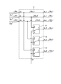
- FIG. 5 is a diagram showing a configuration example of the feedback current adjusting unit 5 according to the first embodiment.
- the electric motor drive device 100 includes a power supply unit 110, a control unit 200, a connection switching signal transmission unit 210, a drive signal transmission unit 220, and a feedback selection signal transmission unit 230.
- the power supply unit 110 includes a power supply unit 1, a feedback current adjusting unit 5, a power conversion unit 4, and a connection switching unit 3.
- the connection switching unit 3 switches each phase winding of the motor 2 to either star connection or delta connection.
- the power supply unit 1 generates electric power to be supplied to the electric motor 2.
- the power conversion unit 4 converts the voltage of the DC power supplied from the power supply unit 1 into AC power having a voltage of an arbitrary AC frequency, and supplies the converted power to the electric motor 2.
- the feedback current adjusting unit 5 performs an operation of adjusting the feedback current including the common mode current that returns from the power conversion unit 4 to the power supply unit 1 via the electric motor 2.
- the power supply unit 1 is a DC power supply that outputs a DC voltage, but the present invention is not limited to this.
- the power supply unit 1 may be a power supply device that generates a DC voltage based on the output of an AC power supply that outputs an AC voltage. In this case, the AC power supply is not included in the components of the power supply unit 1.
- the DC power supply or the AC power supply can be used properly by changing the configuration of the power supply unit 110.
- the electric motor 2 is a connection switching motor in which the connection state of each phase winding can be switched to either star connection or delta connection. Since the electric motor 2 is a connection switching electric motor, the neutral point is separated as shown in the figure. With this configuration, a total of six lead wires 50u_1,50u_2,50v_1,50v_2,50w_1,50w_2 are drawn from the motor 2. Leader wires 50u_1 and 50u_2 are U-phase AC wirings. Leader wires 50v_1, 50v_2 are V-phase AC wirings. The leader wires 50w_1 and 50w_2 are W-phase AC wirings.
- the electric motor 2 and the power supply unit 110 are electrically connected by lead wires 50u_1,50u_2,50v_1,50v_2,50w_1,50w_2.
- the operating power to the electric motor 2 is supplied from the power supply unit 110 through the three lead wires 50u_1, 50v_1, 50w_1 under the control of the control unit 200.
- the electric motor 2 includes a U-phase winding 21, a V-phase winding 22, and a W-phase winding 23. Further, the electric motor 2 has terminals 2u_1, 2, u_2, 2v_1, 2, v_2, 2w_1, 2w_2.
- one end of the U-phase winding 21 is connected to the terminal 2u_1, and the other end of the U-phase winding 21 is connected to the terminal 2u_1.
- One end of the V-phase winding 22 is connected to the terminal 2v_1, and the other end of the V-phase winding 22 is connected to the terminal 2v_1.
- One end of the W-phase winding 23 is connected to the terminal 2w_1, and the other end of the W-phase winding 23 is connected to the terminal 2w_1.
- connection switching unit 3 has a function of switching the connection state of each phase winding of the motor 2 from star connection to delta connection, or from delta connection to star connection.
- the connection switching unit 3 includes a switching device 31, a switching device 32, and a switching device 33, as shown in FIGS. 3 and 4. Further, the connection switching unit 3 has terminals 3u, 3v, 3w, 3u_1,3v_1,3w_1,3u_2,3v_2,3w_2,3N and connection wirings 3u_3,3v_3,3w_3.
- An example of the switch 31, the switch 32, and the switch 33 is a c-contact type switch having contacts d, e, and f, as shown in FIGS. 3 and 4.
- the contact f is connected to the contact d when the power is on, and is connected to the contact e when the power is off.
- the contact f is connected to the contact e when energized and is connected to the contact d when not energized.
- each switch is described as a c-contact type switch, but the present invention is not limited to these examples.
- Each switch may be a switch that can be opened and closed in both directions.
- each switch may be configured by a contact type switch, a b contact type switch, or a combination of both switches.
- each switch may be a semiconductor switch.
- the switch 31, the switch 32, and the switch 33 are driven by the drive signals S11, S21, and S31 output from the connection switching signal transmission unit 210.
- the drive signals S11, S21, and S31 are generated based on the control signals S1, S2, and S3 output from the control unit 200.
- each switch has a small conduction loss when it is turned on, and a mechanical switch such as a relay or a contactor can be used.
- a switching element formed of a wide bandgap semiconductor may be used instead of the mechanical switch.
- the contact d of the switch 31 is connected to the connection wiring 3v_3.
- the connection wiring 3v_3 is a connection wiring for electrically connecting the terminal 3v and the terminal 3v_1 inside the connection switching unit 3.
- the terminal 3v_1 is a terminal connected to the lead wire 50v_1.
- the contact d of the switch 32 is connected to the connection wiring 3w_3.
- the connection wiring 3w_3 is a connection wiring for electrically connecting the terminal 3w and the terminal 3w_1 inside the connection switching unit 3.
- the terminal 3w_1 is a terminal connected to the lead wire 50w_1.
- the contact d of the switch 33 is connected to the connection wiring 3u_3.
- the connection wiring 3u_3 is a connection wiring for electrically connecting the terminal 3u and the terminal 3u_1 inside the connection switching unit 3.
- the terminal 3u_1 is a terminal connected to the lead wire 50u_1.
- Each contact e of the switches 31, 32, 33 is connected to the terminal 3N.
- the contact f of the switch 31 is connected to the terminal 3u_2.
- the terminal 3u_2 is a terminal connected to the lead wire 50u_2. Therefore, the terminal 3u_2 and the terminal 2u_2 of the electric motor 2 are electrically connected by the lead wire 50u_2.
- the contact f of the switch 32 is connected to the terminal 3v_2.
- the terminal 3v_2 is a terminal connected to the lead wire 50v_2. Therefore, the terminal 3v_2 and the terminal 2v_2 of the electric motor 2 are electrically connected by the lead wire 50v_2.
- the contact f of the switch 33 is connected to the terminal 3w_2.
- the terminal 3w_2 is a terminal connected to the lead wire 50w_2. Therefore, the terminal 3w_2 and the terminal 2w_2 of the electric motor 2 are electrically connected by the lead wire 50w_2.
- the contact f of each switch is connected to the contact e. Therefore, the connection state of FIG. 3 in the motor 2 is a star connection. Further, in FIG. 4, the contact f of each switch is connected to the contact d. Therefore, the connection state of FIG. 4 in the motor 2 is a delta connection.
- the power conversion unit 4 has a leg 40u in which the upper arm element 41 and the lower arm element 42 are connected in series, and the upper arm element 43 and the lower arm element 44 are connected in series. It includes a leg 40v and a leg 40w in which an upper arm element 45 and a lower arm element 46 are connected in series.
- the legs 40u, 40v and 40w are connected in parallel to each other.
- the upper arm elements 41, 43, 45 and the lower arm elements 42, 44, 46 exemplify a metal oxide semiconductor field effect transistor (Metal Oxide Semiconductor Field Effect Transistor: MOSFET). Not limited. Insulated gate bipolar transistors (Insulated Gate Bipolar Transistors: IGBTs) may be used instead of the MOSFETs.
- the upper arm elements 41, 43, 45 and the lower arm elements 42, 44, 46 are driven by the drive signals Sup1, Sun1, Sbp1, Svn1, Swp1, Swn1 output from the drive signal transmission unit 220.
- the drive signals Sup1, Sun1, Subp1, Svn1, Swp1, Swn1 are generated based on the control signals Sup, Sun, Spp, Swn, Swp, Swn output from the control unit 200.
- the upper arm element 41 includes a transistor 40a and a diode 40b connected to the transistor 40a in antiparallel.
- the other upper arm elements 43, 45 and lower arm elements 42, 44, 46 have the same configuration.
- Opposite parallel means that the anode of the diode is connected to the source of the MOSFET and the cathode of the diode is connected to the collector of the MOSFET.
- FIG. 2 has a configuration including three legs in which the upper arm element and the lower arm element are connected in series, but the configuration is not limited to this configuration. The number of legs may be four or more.
- the transistor 40a of the upper arm elements 41, 43, 45 and the lower arm elements 42, 44, 46 is a MOSFET
- at least one of the upper arm elements 41, 43, 45 and the lower arm elements 42, 44, 46 is , Silicon carbide, gallium nitride, gallium oxide or diamond may be formed of a wide bandgap semiconductor. If a MOSFET formed of a wide bandgap semiconductor is used, the effects of withstand voltage and heat resistance can be enjoyed.
- the power conversion unit 4 has terminals 4a, 4b, 4u, 4v, 4w.
- the connection point 48u between the upper arm element 41 and the lower arm element 42 is connected to the terminal 4u.
- the connection point 48v between the upper arm element 43 and the lower arm element 44 is connected to the terminal 4v.
- the connection point 48w between the upper arm element 45 and the lower arm element 46 is connected to the terminal 4w.
- the terminal 4u and the terminal 3u of the connection switching unit 3 are electrically connected by the connection line 30u.
- the terminal 4v and the terminal 3v of the connection switching unit 3 are electrically connected by the connection line 30v.
- the terminal 4w and the terminal 3w of the connection switching unit 3 are electrically connected by the connection line 30w.
- connection points of the upper arm elements 41, 43, 45 are connected to the terminal 4a.
- a power line 50a on the high potential side is connected to the terminal 4a.
- the connection points of the lower arm elements 42, 44, 46 are connected to the terminal 4b.
- a power line 50b on the low potential side is connected to the terminal 4b.
- the power supply line 50a on the high potential side may be referred to as a "first power supply line”
- the power supply line 50b on the low potential side may be referred to as a "second power supply line”.
- the feedback current adjusting unit 5 includes bypass capacitors 51 and 52, open / close switches 53 and 55, and coupling capacitors 54, 56, 57, 58 and 59.
- the bypass capacitors 51 and 52 operate as so-called Y capacitors.
- the feedback current adjusting unit 5 has terminals 5u, 5v, 5w, 5N.
- the terminal 5u and the terminal 3u of the connection switching unit 3 are electrically connected by the connection line 32u.
- the terminal 5v and the terminal 3v of the connection switching unit 3 are electrically connected by the connection line 32v.
- the terminal 5w and the terminal 3w of the connection switching unit 3 are electrically connected by the connection line 32w.
- the terminal 5N and the terminal 3N of the connection switching unit 3 are electrically connected by the connection line 32N.
- the open / close switches 53 and 55 are driven by the selection signals Sa1 and Sb1 output from the feedback selection signal transmission unit 230.
- the selection signals Sa1 and Sb1 are generated based on the control signals Sa and Sb output from the control unit 200.
- Power lines 50a and 50b are routed inside the feedback current adjusting unit 5.
- One end of the power supply line 50a is connected to the terminal 4a of the power conversion unit 4 (FIG. 2), and the other end of the power supply line 50a is connected to the terminal 1a of the power supply unit 1 (FIG. 1).
- One end of the power supply line 50b is connected to the terminal 4b of the power conversion unit 4 (FIG. 2), and the other end of the power supply line 50b is connected to the terminal 1b of the power supply unit 1 (FIG. 1).
- the terminal 1a is a high potential side terminal and the terminal 1b is a low potential side terminal.
- the bypass capacitors 51 and 52 are connected in series and arranged between the power supply lines 50a and 50b.
- the bypass capacitor 51 is connected to the power supply line 50a, and the bypass capacitor 52 is connected to the power supply line 50b.
- One end of the coupling capacitor 54 is connected to the midpoint 50c, which is the connection point of the bypass capacitors 51 and 52, via the open / close switch 53.
- the other end of the coupling capacitor 54 is connected to the terminal 5N.
- One end of the coupling capacitor 56 is connected to the midpoint 50c via the open / close switch 55.
- the other end of the coupling capacitor 56 is connected to a connection point 50d between one ends of the coupling capacitors 57, 58, 59.
- the other end of the coupling capacitor 57 is connected to the terminal 5u
- the other end of the coupling capacitor 58 is connected to the terminal 5v
- the other end of the coupling capacitor 59 is connected to the terminal 5w.
- a DC voltage output from the power supply unit 1 is applied to the power conversion unit 4 via the feedback current adjustment unit 5.
- the upper arm elements 41, 43, 45 and the lower arm elements 42, 44, 46 in the power conversion unit 4 apply an AC voltage to the electric motor 2 while the upper and lower arm elements operate in a complementary manner.
- the electric motor 2 is driven by applying a rotating magnetic field by the applied AC voltage.
- connection state of the motor 2 is a star connection
- the contact f of each switch is connected to the contact e.
- the lead wire 50u_2, 50v_2, 50w_2 drawn out from the electric motor 2 is electrically connected to the terminal 3N of the connection switching unit 3 via each switch.
- the upper and lower arm elements of the power conversion unit 4 often perform complementary switching operations.
- the potential of the power supply line 50a on the high potential side and the potential of the power supply line 50b on the low potential side are alternately generated at the connection points 48u, 48v, 48w in the power conversion unit 4.
- the potentials of the connection points 48u, 48v, and 48w fluctuate greatly.
- the neutral point potential of the electric motor 2 also momentarily fluctuates greatly.
- the motor 2 Since the motor 2 is usually surrounded by a frame or the like, it has a stray capacitance between the motor winding and the frame. For example, in the case of an electric motor used in a compressor of an air conditioner, there is a stray capacitance between the electric motor winding and the compressor shell. When the neutral point potential of the motor 2 fluctuates momentarily through this kind of stray capacitance, a common mode current flows to the outside of the motor 2. This common mode current may pass through the ground to the power supply unit 1 and be conducted as common mode noise, which may adversely affect other devices.
- the power supply unit excluding the power supply unit 1 applies the common mode current that flows due to the momentary fluctuation of the neutral point potential of the electric motor 2.
- a current path that is, a circuit loop, is formed between the 110 and the electric motor 2.
- the open / close switch 53 is controlled to be turned on.
- the above-mentioned common mode current can be reduced to the terminal 3N, connection line 32N, terminal 5N, coupling capacitor 54, open / close switch 53, midpoint 50c, bypass capacitor 51 or bypass of the connection switching unit 3. It returns to the power conversion unit 4 via the capacitor 52. That is, the common mode current is fed back via the coupling capacitor 54 and the open / close switch 53 in the feedback current adjusting unit 5. Therefore, the common mode current from the electric motor 2 to the power supply unit 1 via the ground can be reduced. As a result, the outflow of the common mode current to the power supply unit 1 side can be suppressed, and the common mode noise that adversely affects other devices can be suppressed.
- the state of the open / close switch 55 which is the other open / close switch, may be either on or off.
- the common mode current is affected by the presence of the coupling capacitors 56, 57, 58, 59, it is desirable that the open / close switch 55 is controlled to be off.
- connection state of the motor 2 is a delta connection
- the contact f of each switch is connected to the contact d.
- the lead wire 50u_2 drawn out from the electric motor 2 is electrically connected to the terminal 5v of the feedback current adjusting unit 5 via the switch 31, the connecting wiring 3v_3, the terminal 3v, and the connecting wire 32v.
- the lead wire 50v_2 drawn out from the electric motor 2 is electrically connected to the terminal 5w of the feedback current adjusting unit 5 via the switch 32, the connecting wiring 3w_3, the terminal 3w, and the connecting wire 32w.
- the lead wire 50w_2 drawn out from the electric motor 2 is electrically connected to the terminal 5u of the feedback current adjusting unit 5 via the switch 33, the connection wiring 3u_3, the terminal 3u, and the connection line 32u.
- the above-mentioned common mode current is generated even when the connection state of the motor 2 is delta connection. Therefore, as in the case of star connection, control is performed to form a circuit loop for circulating a part of the common mode current toward the power supply unit 1 between the power supply unit 110 excluding the power supply unit 1 and the motor 2. Do.
- the open / close switch 55 is controlled to be turned on.
- the above-mentioned common mode current can be reduced to the terminal 3u, the connection line 32u, the terminal 5u, the coupling capacitor 57, the coupling capacitor 56, the open / close switch 55, and the midpoint 50c of the connection switching unit 3. It returns to the power conversion unit 4 via the bypass capacitor 51 or the bypass capacitor 52. Further, the common mode current passes through the terminal 3v, the connection line 32v, the terminal 5v, the coupling capacitor 58, the coupling capacitor 56, the open / close switch 55, the middle point 50c, the bypass capacitor 51 or the bypass capacitor 52 of the connection switching unit 3.
- the common mode current passes through the terminal 3w, the connection line 32w, the terminal 5w, the coupling capacitor 59, the coupling capacitor 56, the open / close switch 55, the midpoint 50c, the bypass capacitor 51 or the bypass capacitor 52 of the connection switching unit 3.
- the common mode current is fed back via the coupling capacitors 56, 57, 58, 59 and the open / close switch 55 in the feedback current adjusting unit 5. Therefore, the common mode current from the electric motor 2 to the power supply unit 1 via the ground can be reduced. As a result, the outflow of the common mode current to the power supply unit 1 side can be suppressed, and the common mode noise that adversely affects other devices can be suppressed.
- the terminals 5u, 5v, 5w, the coupling capacitors 56, 57, 58, 59 and the open / close switch 55 feed back the feedback current including the common mode current when the connection state of the motor 2 is delta connection. It operates as a first pull-in unit that draws into the current adjusting unit 5.
- the terminal 5N, the coupling capacitor 54, and the open / close switch 53 draw a feedback current including a common mode current into the feedback current adjusting unit 5 when the connection state of the motor 2 is a star connection. Operates as a pull-in part of.
- the winding resistance and inductance in the case of star connection are equivalently three times the winding resistance and inductance in the case of delta connection. Therefore, the impedance of the delta connection is lower than that of the star connection, and the common mode current easily flows. As a result, the common mode noise may be larger in the delta connection than in the star connection. Therefore, in the first embodiment, when the connection state of the motor 2 is a delta connection, the path of the common mode current circulating in the device via the feedback current adjusting unit 5 is tripled as in the case of the star connection. There is. As a result, in the case of delta connection, the amount of common mode current circulating in the device can be increased, and the amount of common mode current flowing out to the power supply unit 1 side can be made equal between the delta connection and the star connection. ..
- the state of the open / close switch 53 which is the other open / close switch, may be either on or off.
- the open / close switch 53 is controlled to be off.
- the capacitance of at least one of the coupling capacitors 54, 56, 57, 58, 59 can be adjusted. Something is desirable.
- the coupling capacitors 54 or the coupling capacitors 56, 57, 58, 59 are arranged in both paths so that the connection state of the motor 2 can correspond to both the case of the delta connection and the case of the star connection.
- the configuration is not limited to that shown in FIG. As mentioned above, the influence of the common mode current is considered to be greater in the delta connection. Therefore, from the configuration of FIG. 1, the open / close switch 53 and the coupling capacitor 54 may be omitted, and a configuration that can handle only the case of delta connection may be used.
- the open / close switch 55 is omitted, and a circuit loop for returning the common mode current is always formed through the coupling capacitors 56, 57, 58, 59.
- the feedback current adjusting unit 5 may be configured.
- the open / close switch 53 and the coupling capacitor 54 may be mounted or not mounted according to the motor type or the device configuration.
- a capacitor is illustrated as an example of an element for adjusting the common mode current, but the present invention is not limited to this. Any element may be used as long as it can adjust the common mode current.
- each of the coupling capacitors 54, 56, 57, 58, 59 may be replaced with a resistance element.
- the power supply unit 110 at least two components of the connection switching unit 3, the power conversion unit 4, and the feedback current adjusting unit 5 may be mounted on the same substrate.
- the connection switching unit 3 since the electric neutral point is inside the electric motor, the distance between the electric neutral point and the power conversion unit 4 becomes long. Therefore, the adjustment of the common mode current is easily affected by the AC wiring.
- the electrical neutral point is inside the connection switching unit 3. Therefore, if the connection switching unit 3 and the power conversion unit 4 are mounted on the same substrate, the distance between the electrical neutral point of the connection switching unit 3 and the power conversion unit 4 can be shortened. As a result, the influence of the AC wiring can be reduced when adjusting the common mode current. Further, since the distance between the electrical neutral point of the connection switching unit 3 and the power conversion unit 4 can be shortened, the stray capacitance existing between the wiring path and the ground can be reduced. Therefore, the magnitude of the common mode current itself that can flow from the electric motor 2 via the ground via the stray capacitance can be reduced. Thereby, the generation of common mode noise can be reduced.
- connection switching unit 3 and the feedback current adjusting unit 5 are mounted on the same substrate, the distance between the electrical neutral point of the wiring switching unit 3 and the feedback current adjusting unit 5 can be shortened. As a result, the influence of the AC wiring can be reduced when adjusting the common mode current.
- connection switching unit 3 the power conversion unit 4, and the feedback current adjusting unit 5 are mounted on the same board, the above-mentioned terminals can be provided on the board. With this configuration, the connection between the various lead wires drawn from the electric motor 2 and the various power supply lines drawn from the power supply unit 1 becomes easier than in the case of a general electric motor.
- FIG. 6 is a diagram showing a configuration of a modified example of the electric motor drive device 100A according to the first embodiment.
- the power supply unit 110 is replaced with the power supply unit 110A in the configuration of the electric motor drive device 100 shown in FIG.
- the feedback current adjusting unit 5 is replaced with the feedback current adjusting unit 5A.
- a terminal 5N_2 to be further grounded is provided in the feedback current adjusting unit 5A.
- the other configurations are the same as or equivalent to the configurations shown in FIG. 1, and the same or equivalent components are designated by the same reference numerals, and redundant description will be omitted.
- FIG. 7 is a diagram showing a configuration example of the feedback current adjusting unit 5A shown in FIG.
- the midpoint 50c is electrically connected to the terminal 5N_2.
- the potential at the midpoint 50c is set to the same potential as the ground (GND). That is, the potential at the midpoint 50c is the ground potential.
- the other configurations are the same as or equivalent to the configuration shown in FIG. 5, and the same or equivalent components are designated by the same reference numerals, and redundant description will be omitted.
- the potential at the midpoint 50c is set as the ground potential via the terminal 5N_2 provided in the feedback current adjusting unit 5A, but the configuration is not limited to this.
- the equivalent terminal and the midpoint 50c may be electrically connected.
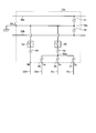
- FIG. 8 is a diagram showing a configuration example when the AC / DC converter is included in the power supply unit 1 shown in FIGS. 1 and 6.
- the power supply unit 1 includes an AC / DC converter 8 connected to the AC power supply 10.
- the AC / DC converter 8 includes four switching elements 11, 12, 13, and 14 that are bridge-connected.
- the AC voltage output from the AC power supply 10 is applied between the connection points of the switching elements 11 and 12 and the connection points of the switching elements 13 and 14 via the reactor 15.
- the switching elements 11, 12, 13, and 14 are switched and controlled by the control unit 200, generate a boosted voltage, and output the boosted voltage from the terminals 1a and 1b.
- the power supply unit 1 includes the AC / DC converter 8 having the configuration shown in FIG. 8, a common mode current is generated due to the switching operation of the switching elements 11, 12, 13, and 14. A part of this common mode current may be suppressed by the feedback current adjusting units 5 and 5A in the first embodiment. Therefore, the feedback current adjusting units 5 and 5A in the first embodiment are effective for adjusting the common mode current when the power supply unit 1 has the configuration shown in FIG.
- FIG. 9 is a diagram showing a configuration example different from that of FIG. 8 when the power supply unit 1A includes an AC / DC converter.
- the AC / DC converter 8A in which the switching element 11 is replaced with the diode 11a and the switching element 13 is replaced with the diode 13a is shown.
- a common mode current is generated by the switching operation of the switching elements 12 and 14. Therefore, the feedback current adjusting units 5 and 5A in the first embodiment are effective for adjusting the common mode current even when the power supply unit 1A includes the AC / DC converter 8A shown in FIG.
- FIG. 10 is a diagram showing a configuration example different from that of FIGS. 8 and 9 when the power supply unit 1B includes an AC / DC converter.
- the power supply unit 1B shown in FIG. 10 in the configuration of the power supply unit 1 shown in FIG. 8, the AC / DC converter 8B in which the switching element 13 is replaced with the diode 13b and the switching element 14 is replaced with the diode 14b is shown. ing. Also in the configuration shown in FIG. 10, a common mode current is generated by the switching operation of the switching elements 11 and 12. Therefore, the feedback current adjusting units 5 and 5A in the first embodiment are effective for adjusting the common mode current even when the power supply unit 1B includes the AC / DC converter 8B shown in FIG.
- the electric motor drive device for driving the electric motor configured so that the connection state of each phase winding can be switched to either star connection or delta connection is from the power conversion unit. It is provided with a feedback current adjusting unit that adjusts a feedback current including a common mode current that returns to the power supply unit via an electric motor. According to this feedback current adjusting unit, the common mode current from the electric motor to the power supply unit via the ground can be reduced. As a result, the outflow of the common mode current to the power supply unit side can be suppressed, and the common mode noise that adversely affects other devices can be suppressed.
- the feedback current adjusting unit includes a first lead-in unit that draws in the feedback current when the connection state of the motor is delta connection via the connection switching unit.
- the feedback current adjusting unit includes a second lead-in portion that draws in the feedback current when the connection state of the motor is star connection through the connection switching unit.
- the feedback current adjusting unit is configured to be able to select whether or not to draw in the feedback current. Thereby, it is possible to decide whether to mount or not to mount the motor according to the motor type or the device configuration.
- the power conversion unit the connection switching unit, and the feedback current adjusting unit, which are the components of the electric motor drive device, may be mounted on the same substrate.
- the influence of the AC wiring can be reduced when adjusting the common mode current.
- the connection between the various lead wires drawn from the electric motor and the various power supply lines drawn from the power supply unit becomes easier than in the case of a general electric motor.
- connection switching unit and the power conversion unit are mounted on the same board, the stray capacitance existing between the wiring path and the ground can be reduced. Thereby, the generation of common mode noise can be reduced.
- FIG. 11 is a block diagram showing an example of a hardware configuration that realizes the function of the control unit 200 according to the first embodiment.
- FIG. 12 is a block diagram showing another example of the hardware configuration that realizes the function of the control unit 200 according to the first embodiment.
- the processor 300 that performs the calculation
- the memory 302 that stores the program read by the processor 300
- the input / output of the signal are input / output. It can be configured to include the interface 304 to be performed.
- the processor 300 may be an arithmetic unit, a microprocessor, a microcomputer, a CPU (Central Processing Unit), or a DSP (Digital Signal Processor).
- the memory 302 includes a non-volatile or volatile semiconductor memory such as a RAM (Random Access Memory), a ROM (Read Only Memory), a flash memory, an EPROM (Erasable Program ROM), and an EPROM (registered trademark) (Electrically EPROM). Examples thereof include magnetic disks, flexible disks, optical disks, compact disks, mini disks, and DVDs (Digital entirely Disc).
- the memory 302 stores a program that executes the function of the control unit 200 according to the first embodiment.
- the processor 300 sends and receives necessary information via the interface 304, the processor 300 executes a program stored in the memory 302, and the processor 300 refers to a table stored in the memory 302 to perform the above-described processing. It can be carried out.
- the calculation result by the processor 300 can be stored in the memory 302.
- the processing circuit 305 shown in FIG. 12 can also be used.
- the processing circuit 305 corresponds to a single circuit, a composite circuit, an ASIC (Application Specific Integrated Circuit), an FPGA (Field-Programmable Gate Array), or a combination thereof.
- the information input to the processing circuit 305 and the information output from the processing circuit 305 can be obtained via the interface 304. Even in the configuration using the processing circuit 305, some processing in the control unit 200 may be performed by the processor 300 having the configuration shown in FIG.
- FIG. 13 is a diagram showing a configuration example of the air conditioner 240 according to the second embodiment.
- the air conditioner 240 according to the second embodiment includes the electric motor driving device 100 described in the first embodiment.
- the compressor 251 incorporating the electric motor 2 in the first embodiment, the four-way valve 259, the outdoor heat exchanger 252, the expansion valve 261 and the indoor heat exchanger 257 are connected via a refrigerant pipe 262. It is equipped with a refrigeration cycle installed in the air conditioner to form a separate air conditioner.
- the components having the same or equivalent functions as those of the first embodiment are designated by the same reference numerals as those of the first embodiment.
- a refrigeration cycle is configured in which the refrigerant circulates between the compressor 251 and the outdoor heat exchanger 252 and between the compressor 251 and the indoor heat exchanger 257 to perform heating and cooling.
- the configuration shown in FIG. 13 can be applied not only to an air conditioner but also to a refrigerating cycle apparatus including a refrigerating cycle such as a refrigerator and a freezer.
- 1,1A, 1B Power supply unit 1a, 1b, 2u_1,2u_2,2v_1,2v_2,2w_1,2w_2,3N, 3u, 3v, 3w, 3u_1,3v_1,3w_1,3u_2,3v_2,3w_2,4a, 4b, 4u, 4v, 4w, 5N, 5u, 5v, 5w terminal, 2 electric motor, 3 connection switching part, 3u_3, 3v_3, 3w_3 connection wiring, 4 power conversion part, 5,5A feedback current adjustment part, 8,8A, 8B AC / DC conversion Instrument, 10 AC power supply, 11, 12, 13, 14 switching element, 11a, 13a, 13b, 14b, 40b diode, 21 U-phase winding, 22 V-phase winding, 23 W-phase winding, 30u, 30v, 30w , 32N, 32u, 32v, 32w connection line, 31, 32, 33 switch, 40a transistor, 40u, 40v, 40w leg, 41, 43, 45 upper
Landscapes
- Engineering & Computer Science (AREA)
- Power Engineering (AREA)
- Control Of Ac Motors In General (AREA)
- Inverter Devices (AREA)
Priority Applications (2)
| Application Number | Priority Date | Filing Date | Title |
|---|---|---|---|
| JP2021541948A JP7221400B2 (ja) | 2019-08-30 | 2019-08-30 | 電動機駆動装置、空気調和機及び冷凍サイクル装置 |
| PCT/JP2019/034258 WO2021038864A1 (ja) | 2019-08-30 | 2019-08-30 | 電動機駆動装置、空気調和機及び冷凍サイクル装置 |
Applications Claiming Priority (1)
| Application Number | Priority Date | Filing Date | Title |
|---|---|---|---|
| PCT/JP2019/034258 WO2021038864A1 (ja) | 2019-08-30 | 2019-08-30 | 電動機駆動装置、空気調和機及び冷凍サイクル装置 |
Publications (1)
| Publication Number | Publication Date |
|---|---|
| WO2021038864A1 true WO2021038864A1 (ja) | 2021-03-04 |
Family
ID=74684368
Family Applications (1)
| Application Number | Title | Priority Date | Filing Date |
|---|---|---|---|
| PCT/JP2019/034258 Ceased WO2021038864A1 (ja) | 2019-08-30 | 2019-08-30 | 電動機駆動装置、空気調和機及び冷凍サイクル装置 |
Country Status (2)
| Country | Link |
|---|---|
| JP (1) | JP7221400B2 (https=) |
| WO (1) | WO2021038864A1 (https=) |
Citations (3)
| Publication number | Priority date | Publication date | Assignee | Title |
|---|---|---|---|---|
| JPH11235081A (ja) * | 1998-02-20 | 1999-08-27 | Hitachi Ltd | 負荷装置駆動システム |
| JP2008228513A (ja) * | 2007-03-15 | 2008-09-25 | Mitsubishi Electric Corp | 電動機駆動装置および電動機駆動方法並びに冷凍空調装置 |
| WO2019026257A1 (ja) * | 2017-08-03 | 2019-02-07 | 三菱電機株式会社 | 電動機システムおよび電動機システムを備える室外機 |
-
2019
- 2019-08-30 WO PCT/JP2019/034258 patent/WO2021038864A1/ja not_active Ceased
- 2019-08-30 JP JP2021541948A patent/JP7221400B2/ja active Active
Patent Citations (3)
| Publication number | Priority date | Publication date | Assignee | Title |
|---|---|---|---|---|
| JPH11235081A (ja) * | 1998-02-20 | 1999-08-27 | Hitachi Ltd | 負荷装置駆動システム |
| JP2008228513A (ja) * | 2007-03-15 | 2008-09-25 | Mitsubishi Electric Corp | 電動機駆動装置および電動機駆動方法並びに冷凍空調装置 |
| WO2019026257A1 (ja) * | 2017-08-03 | 2019-02-07 | 三菱電機株式会社 | 電動機システムおよび電動機システムを備える室外機 |
Also Published As
| Publication number | Publication date |
|---|---|
| JP7221400B2 (ja) | 2023-02-13 |
| JPWO2021038864A1 (https=) | 2021-03-04 |
Similar Documents
| Publication | Publication Date | Title |
|---|---|---|
| JP5584357B2 (ja) | 可変速駆動装置 | |
| JP5444381B2 (ja) | 可変速駆動装置内の直流リンクをプリチャージするシステム | |
| US9590540B2 (en) | Hybrid pulse width modulation method for variable speed drive | |
| US7005829B2 (en) | System for precharging a DC link in a variable speed drive | |
| US9698709B2 (en) | Motor driving device | |
| US20190348941A1 (en) | Electric-motor driving apparatus, refrigeration cycle apparatus, and air conditioner | |
| US7555912B2 (en) | System for precharging a DC link in a variable speed drive | |
| US6373728B1 (en) | Frequency converter with an intermediate buck-boost converter for controlling an electric motor | |
| CN105765851A (zh) | 电力转换装置、具备其的电动机驱动装置、具备其的鼓风机、压缩机、以及具备这些的空调机、冰箱和制冷机 | |
| AU2016404961B9 (en) | Motor drive apparatus and air conditioner | |
| WO2007029544A1 (ja) | インバータ装置および冷凍サイクル装置 | |
| JP7221400B2 (ja) | 電動機駆動装置、空気調和機及び冷凍サイクル装置 | |
| US10978982B2 (en) | Method and device for operating an electronically commutated electrical machine in the event of a fault | |
| WO2022009270A1 (ja) | モータ駆動装置及び空気調和装置 | |
| WO2020255249A1 (ja) | 電力変換装置、冷凍サイクル装置および空気調和装置 | |
| JP2011244576A (ja) | 誘導電動機の駆動装置 | |
| JP7471509B2 (ja) | 直流電源装置、冷凍サイクル装置、空気調和機および冷蔵庫 | |
| JP7631930B2 (ja) | インバータ装置及びインバータモジュール | |
| JP6921272B2 (ja) | 電動機駆動装置、冷凍サイクル装置及び空気調和機 | |
| TWI806989B (zh) | 電力轉換裝置及具備此之空調機 | |
| JPWO2020066029A1 (ja) | モータ駆動装置及び空気調和機 | |
| WO2023176281A1 (ja) | 電力変換装置 | |
| WO2025083865A1 (ja) | ヒートポンプ装置および駆動回路 | |
| JP2024101638A (ja) | モータユニット及びそれを備えた電動コンプレッサ | |
| JP2010124540A (ja) | モーター制御装置、この制御装置を用いた冷凍空調装置及び家電機器 |
Legal Events
| Date | Code | Title | Description |
|---|---|---|---|
| 121 | Ep: the epo has been informed by wipo that ep was designated in this application |
Ref document number: 19943081 Country of ref document: EP Kind code of ref document: A1 |
|
| ENP | Entry into the national phase |
Ref document number: 2021541948 Country of ref document: JP Kind code of ref document: A |
|
| NENP | Non-entry into the national phase |
Ref country code: DE |
|
| 122 | Ep: pct application non-entry in european phase |
Ref document number: 19943081 Country of ref document: EP Kind code of ref document: A1 |