WO2021033634A1 - Film optique - Google Patents
Film optique Download PDFInfo
- Publication number
- WO2021033634A1 WO2021033634A1 PCT/JP2020/030863 JP2020030863W WO2021033634A1 WO 2021033634 A1 WO2021033634 A1 WO 2021033634A1 JP 2020030863 W JP2020030863 W JP 2020030863W WO 2021033634 A1 WO2021033634 A1 WO 2021033634A1
- Authority
- WO
- WIPO (PCT)
- Prior art keywords
- liquid crystal
- optical film
- compound
- group
- crystal compound
- Prior art date
Links
- 239000012788 optical film Substances 0.000 title claims abstract description 79
- 150000001875 compounds Chemical class 0.000 claims abstract description 217
- 239000004973 liquid crystal related substance Substances 0.000 claims abstract description 148
- 239000011347 resin Substances 0.000 claims abstract description 105
- 229920005989 resin Polymers 0.000 claims abstract description 105
- 125000005842 heteroatom Chemical group 0.000 claims abstract description 33
- 239000000758 substrate Substances 0.000 claims abstract description 15
- 238000010884 ion-beam technique Methods 0.000 claims abstract description 8
- 239000000203 mixture Substances 0.000 claims description 97
- 239000000463 material Substances 0.000 claims description 77
- 239000010408 film Substances 0.000 claims description 48
- 229920000642 polymer Polymers 0.000 claims description 42
- 229920002678 cellulose Polymers 0.000 claims description 20
- 239000001913 cellulose Substances 0.000 claims description 18
- ODIGIKRIUKFKHP-UHFFFAOYSA-N (n-propan-2-yloxycarbonylanilino) acetate Chemical compound CC(C)OC(=O)N(OC(C)=O)C1=CC=CC=C1 ODIGIKRIUKFKHP-UHFFFAOYSA-N 0.000 claims description 17
- 125000003368 amide group Chemical group 0.000 claims description 8
- 125000004185 ester group Chemical group 0.000 claims description 8
- JOYRKODLDBILNP-UHFFFAOYSA-N urethane group Chemical group NC(=O)OCC JOYRKODLDBILNP-UHFFFAOYSA-N 0.000 claims description 8
- 230000001678 irradiating effect Effects 0.000 claims description 6
- 238000001004 secondary ion mass spectrometry Methods 0.000 claims description 4
- 125000005620 boronic acid group Chemical group 0.000 claims description 3
- 230000003287 optical effect Effects 0.000 abstract description 20
- 230000007547 defect Effects 0.000 abstract description 11
- 238000005011 time of flight secondary ion mass spectroscopy Methods 0.000 abstract description 9
- 238000002042 time-of-flight secondary ion mass spectrometry Methods 0.000 abstract description 9
- 239000010410 layer Substances 0.000 description 143
- UWCWUCKPEYNDNV-LBPRGKRZSA-N 2,6-dimethyl-n-[[(2s)-pyrrolidin-2-yl]methyl]aniline Chemical compound CC1=CC=CC(C)=C1NC[C@H]1NCCC1 UWCWUCKPEYNDNV-LBPRGKRZSA-N 0.000 description 104
- 230000001939 inductive effect Effects 0.000 description 53
- 238000000034 method Methods 0.000 description 36
- 230000000694 effects Effects 0.000 description 25
- 125000005647 linker group Chemical group 0.000 description 19
- 239000002904 solvent Substances 0.000 description 17
- 239000003795 chemical substances by application Substances 0.000 description 16
- 125000001931 aliphatic group Chemical group 0.000 description 13
- -1 Polyethylene Polymers 0.000 description 11
- 238000010438 heat treatment Methods 0.000 description 11
- QVGXLLKOCUKJST-UHFFFAOYSA-N atomic oxygen Chemical compound [O] QVGXLLKOCUKJST-UHFFFAOYSA-N 0.000 description 9
- 229910052760 oxygen Inorganic materials 0.000 description 9
- 239000001301 oxygen Substances 0.000 description 9
- 230000036961 partial effect Effects 0.000 description 9
- 125000001424 substituent group Chemical group 0.000 description 9
- 150000002500 ions Chemical class 0.000 description 8
- 238000006116 polymerization reaction Methods 0.000 description 8
- 230000001105 regulatory effect Effects 0.000 description 7
- YMWUJEATGCHHMB-UHFFFAOYSA-N Dichloromethane Chemical compound ClCCl YMWUJEATGCHHMB-UHFFFAOYSA-N 0.000 description 6
- OKKJLVBELUTLKV-UHFFFAOYSA-N Methanol Chemical compound OC OKKJLVBELUTLKV-UHFFFAOYSA-N 0.000 description 6
- 230000007423 decrease Effects 0.000 description 6
- 239000003505 polymerization initiator Substances 0.000 description 6
- 238000004804 winding Methods 0.000 description 6
- KLDXJTOLSGUMSJ-JGWLITMVSA-N Isosorbide Chemical compound O[C@@H]1CO[C@@H]2[C@@H](O)CO[C@@H]21 KLDXJTOLSGUMSJ-JGWLITMVSA-N 0.000 description 5
- NIXOWILDQLNWCW-UHFFFAOYSA-N acrylic acid group Chemical group C(C=C)(=O)O NIXOWILDQLNWCW-UHFFFAOYSA-N 0.000 description 5
- 229910052799 carbon Inorganic materials 0.000 description 5
- 230000008859 change Effects 0.000 description 5
- 229960002479 isosorbide Drugs 0.000 description 5
- 238000004519 manufacturing process Methods 0.000 description 5
- 238000007699 photoisomerization reaction Methods 0.000 description 5
- 239000007787 solid Substances 0.000 description 5
- LRHPLDYGYMQRHN-UHFFFAOYSA-N N-Butanol Chemical compound CCCCO LRHPLDYGYMQRHN-UHFFFAOYSA-N 0.000 description 4
- 150000001338 aliphatic hydrocarbons Chemical class 0.000 description 4
- 125000000217 alkyl group Chemical group 0.000 description 4
- 150000001721 carbon Chemical group 0.000 description 4
- 230000000052 comparative effect Effects 0.000 description 4
- 238000001723 curing Methods 0.000 description 4
- 230000003100 immobilizing effect Effects 0.000 description 4
- 150000002605 large molecules Chemical class 0.000 description 4
- 230000002829 reductive effect Effects 0.000 description 4
- 150000003384 small molecules Chemical class 0.000 description 4
- ZCYVEMRRCGMTRW-UHFFFAOYSA-N 7553-56-2 Chemical compound [I] ZCYVEMRRCGMTRW-UHFFFAOYSA-N 0.000 description 3
- UHOVQNZJYSORNB-UHFFFAOYSA-N Benzene Chemical group C1=CC=CC=C1 UHOVQNZJYSORNB-UHFFFAOYSA-N 0.000 description 3
- 239000004743 Polypropylene Substances 0.000 description 3
- 239000004793 Polystyrene Substances 0.000 description 3
- VYPSYNLAJGMNEJ-UHFFFAOYSA-N Silicium dioxide Chemical compound O=[Si]=O VYPSYNLAJGMNEJ-UHFFFAOYSA-N 0.000 description 3
- 150000001408 amides Chemical group 0.000 description 3
- 238000004458 analytical method Methods 0.000 description 3
- ZDZHCHYQNPQSGG-UHFFFAOYSA-N binaphthyl group Chemical group C1(=CC=CC2=CC=CC=C12)C1=CC=CC2=CC=CC=C12 ZDZHCHYQNPQSGG-UHFFFAOYSA-N 0.000 description 3
- 125000004432 carbon atom Chemical group C* 0.000 description 3
- 238000000576 coating method Methods 0.000 description 3
- 229920001577 copolymer Polymers 0.000 description 3
- 238000010894 electron beam technology Methods 0.000 description 3
- 239000003999 initiator Substances 0.000 description 3
- 229910052740 iodine Inorganic materials 0.000 description 3
- 239000011630 iodine Substances 0.000 description 3
- 229910052757 nitrogen Inorganic materials 0.000 description 3
- 125000004433 nitrogen atom Chemical group N* 0.000 description 3
- HXITXNWTGFUOAU-UHFFFAOYSA-N phenylboronic acid Chemical group OB(O)C1=CC=CC=C1 HXITXNWTGFUOAU-UHFFFAOYSA-N 0.000 description 3
- 229920002223 polystyrene Polymers 0.000 description 3
- 239000000126 substance Substances 0.000 description 3
- 238000012360 testing method Methods 0.000 description 3
- HRPVXLWXLXDGHG-UHFFFAOYSA-N Acrylamide Chemical group NC(=O)C=C HRPVXLWXLXDGHG-UHFFFAOYSA-N 0.000 description 2
- NIXOWILDQLNWCW-UHFFFAOYSA-M Acrylate Chemical compound [O-]C(=O)C=C NIXOWILDQLNWCW-UHFFFAOYSA-M 0.000 description 2
- 229910002012 Aerosil® Inorganic materials 0.000 description 2
- ZOXJGFHDIHLPTG-UHFFFAOYSA-N Boron Chemical group [B] ZOXJGFHDIHLPTG-UHFFFAOYSA-N 0.000 description 2
- RTZKZFJDLAIYFH-UHFFFAOYSA-N Diethyl ether Chemical compound CCOCC RTZKZFJDLAIYFH-UHFFFAOYSA-N 0.000 description 2
- 125000003647 acryloyl group Chemical group O=C([*])C([H])=C([H])[H] 0.000 description 2
- 238000012644 addition polymerization Methods 0.000 description 2
- 239000000654 additive Substances 0.000 description 2
- 125000002723 alicyclic group Chemical group 0.000 description 2
- 125000003118 aryl group Chemical group 0.000 description 2
- 125000000732 arylene group Chemical group 0.000 description 2
- DMLAVOWQYNRWNQ-UHFFFAOYSA-N azobenzene Chemical compound C1=CC=CC=C1N=NC1=CC=CC=C1 DMLAVOWQYNRWNQ-UHFFFAOYSA-N 0.000 description 2
- 229910052796 boron Inorganic materials 0.000 description 2
- ZADPBFCGQRWHPN-UHFFFAOYSA-N boronic acid Chemical compound OBO ZADPBFCGQRWHPN-UHFFFAOYSA-N 0.000 description 2
- 238000011088 calibration curve Methods 0.000 description 2
- 238000006243 chemical reaction Methods 0.000 description 2
- 239000011248 coating agent Substances 0.000 description 2
- 239000012792 core layer Substances 0.000 description 2
- 150000001925 cycloalkenes Chemical group 0.000 description 2
- 238000010586 diagram Methods 0.000 description 2
- 239000006185 dispersion Substances 0.000 description 2
- 238000001035 drying Methods 0.000 description 2
- 150000002148 esters Chemical class 0.000 description 2
- FKRCODPIKNYEAC-UHFFFAOYSA-N ethyl propionate Chemical compound CCOC(=O)CC FKRCODPIKNYEAC-UHFFFAOYSA-N 0.000 description 2
- 239000012634 fragment Substances 0.000 description 2
- 125000000524 functional group Chemical group 0.000 description 2
- 238000005227 gel permeation chromatography Methods 0.000 description 2
- 238000007756 gravure coating Methods 0.000 description 2
- 125000004435 hydrogen atom Chemical group [H]* 0.000 description 2
- 125000002887 hydroxy group Chemical group [H]O* 0.000 description 2
- 230000006872 improvement Effects 0.000 description 2
- 239000003112 inhibitor Substances 0.000 description 2
- 239000011254 layer-forming composition Substances 0.000 description 2
- 239000007788 liquid Substances 0.000 description 2
- 238000005259 measurement Methods 0.000 description 2
- QSHDDOUJBYECFT-UHFFFAOYSA-N mercury Chemical compound [Hg] QSHDDOUJBYECFT-UHFFFAOYSA-N 0.000 description 2
- 229910052753 mercury Inorganic materials 0.000 description 2
- 229910052751 metal Inorganic materials 0.000 description 2
- 239000002184 metal Substances 0.000 description 2
- 239000000178 monomer Substances 0.000 description 2
- JFNLZVQOOSMTJK-KNVOCYPGSA-N norbornene Chemical compound C1[C@@H]2CC[C@H]1C=C2 JFNLZVQOOSMTJK-KNVOCYPGSA-N 0.000 description 2
- 125000004430 oxygen atom Chemical group O* 0.000 description 2
- 229920003229 poly(methyl methacrylate) Polymers 0.000 description 2
- 239000004417 polycarbonate Substances 0.000 description 2
- 229920000515 polycarbonate Polymers 0.000 description 2
- 230000000379 polymerizing effect Effects 0.000 description 2
- 239000004926 polymethyl methacrylate Substances 0.000 description 2
- 229920000098 polyolefin Polymers 0.000 description 2
- 239000011148 porous material Substances 0.000 description 2
- 230000008569 process Effects 0.000 description 2
- 230000005855 radiation Effects 0.000 description 2
- 238000001228 spectrum Methods 0.000 description 2
- 238000004544 sputter deposition Methods 0.000 description 2
- PJANXHGTPQOBST-UHFFFAOYSA-N stilbene Chemical group C=1C=CC=CC=1C=CC1=CC=CC=C1 PJANXHGTPQOBST-UHFFFAOYSA-N 0.000 description 2
- 125000005504 styryl group Chemical group 0.000 description 2
- 229910052717 sulfur Inorganic materials 0.000 description 2
- 125000004434 sulfur atom Chemical group 0.000 description 2
- 239000004094 surface-active agent Substances 0.000 description 2
- DQFBYFPFKXHELB-VAWYXSNFSA-N trans-chalcone Chemical compound C=1C=CC=CC=1C(=O)\C=C\C1=CC=CC=C1 DQFBYFPFKXHELB-VAWYXSNFSA-N 0.000 description 2
- 238000002834 transmittance Methods 0.000 description 2
- 230000032258 transport Effects 0.000 description 2
- 125000000391 vinyl group Chemical group [H]C([*])=C([H])[H] 0.000 description 2
- KLDXJTOLSGUMSJ-BXKVDMCESA-N (3s,3as,6s,6as)-2,3,3a,5,6,6a-hexahydrofuro[3,2-b]furan-3,6-diol Chemical compound O[C@H]1CO[C@H]2[C@@H](O)CO[C@H]21 KLDXJTOLSGUMSJ-BXKVDMCESA-N 0.000 description 1
- OKTJSMMVPCPJKN-UHFFFAOYSA-N Carbon Chemical compound [C] OKTJSMMVPCPJKN-UHFFFAOYSA-N 0.000 description 1
- 239000004215 Carbon black (E152) Substances 0.000 description 1
- BVKZGUZCCUSVTD-UHFFFAOYSA-L Carbonate Chemical compound [O-]C([O-])=O BVKZGUZCCUSVTD-UHFFFAOYSA-L 0.000 description 1
- 229920000298 Cellophane Polymers 0.000 description 1
- 229920008347 Cellulose acetate propionate Polymers 0.000 description 1
- 229920001747 Cellulose diacetate Polymers 0.000 description 1
- 229920002284 Cellulose triacetate Polymers 0.000 description 1
- DQFBYFPFKXHELB-UHFFFAOYSA-N Chalcone Natural products C=1C=CC=CC=1C(=O)C=CC1=CC=CC=C1 DQFBYFPFKXHELB-UHFFFAOYSA-N 0.000 description 1
- 239000004986 Cholesteric liquid crystals (ChLC) Substances 0.000 description 1
- 229920000089 Cyclic olefin copolymer Polymers 0.000 description 1
- 239000004985 Discotic Liquid Crystal Substance Substances 0.000 description 1
- VGGSQFUCUMXWEO-UHFFFAOYSA-N Ethene Chemical compound C=C VGGSQFUCUMXWEO-UHFFFAOYSA-N 0.000 description 1
- 239000005977 Ethylene Substances 0.000 description 1
- YCKRFDGAMUMZLT-UHFFFAOYSA-N Fluorine atom Chemical compound [F] YCKRFDGAMUMZLT-UHFFFAOYSA-N 0.000 description 1
- DGAQECJNVWCQMB-PUAWFVPOSA-M Ilexoside XXIX Chemical compound C[C@@H]1CC[C@@]2(CC[C@@]3(C(=CC[C@H]4[C@]3(CC[C@@H]5[C@@]4(CC[C@@H](C5(C)C)OS(=O)(=O)[O-])C)C)[C@@H]2[C@]1(C)O)C)C(=O)O[C@H]6[C@@H]([C@H]([C@@H]([C@H](O6)CO)O)O)O.[Na+] DGAQECJNVWCQMB-PUAWFVPOSA-M 0.000 description 1
- CERQOIWHTDAKMF-UHFFFAOYSA-M Methacrylate Chemical compound CC(=C)C([O-])=O CERQOIWHTDAKMF-UHFFFAOYSA-M 0.000 description 1
- NTIZESTWPVYFNL-UHFFFAOYSA-N Methyl isobutyl ketone Chemical compound CC(C)CC(C)=O NTIZESTWPVYFNL-UHFFFAOYSA-N 0.000 description 1
- UIHCLUNTQKBZGK-UHFFFAOYSA-N Methyl isobutyl ketone Natural products CCC(C)C(C)=O UIHCLUNTQKBZGK-UHFFFAOYSA-N 0.000 description 1
- VVQNEPGJFQJSBK-UHFFFAOYSA-N Methyl methacrylate Chemical class COC(=O)C(C)=C VVQNEPGJFQJSBK-UHFFFAOYSA-N 0.000 description 1
- 239000004695 Polyether sulfone Substances 0.000 description 1
- 239000004698 Polyethylene Substances 0.000 description 1
- 239000004721 Polyphenylene oxide Substances 0.000 description 1
- 239000004372 Polyvinyl alcohol Substances 0.000 description 1
- 229910000831 Steel Inorganic materials 0.000 description 1
- WYURNTSHIVDZCO-UHFFFAOYSA-N Tetrahydrofuran Chemical compound C1CCOC1 WYURNTSHIVDZCO-UHFFFAOYSA-N 0.000 description 1
- NNLVGZFZQQXQNW-ADJNRHBOSA-N [(2r,3r,4s,5r,6s)-4,5-diacetyloxy-3-[(2s,3r,4s,5r,6r)-3,4,5-triacetyloxy-6-(acetyloxymethyl)oxan-2-yl]oxy-6-[(2r,3r,4s,5r,6s)-4,5,6-triacetyloxy-2-(acetyloxymethyl)oxan-3-yl]oxyoxan-2-yl]methyl acetate Chemical compound O([C@@H]1O[C@@H]([C@H]([C@H](OC(C)=O)[C@H]1OC(C)=O)O[C@H]1[C@@H]([C@@H](OC(C)=O)[C@H](OC(C)=O)[C@@H](COC(C)=O)O1)OC(C)=O)COC(=O)C)[C@@H]1[C@@H](COC(C)=O)O[C@@H](OC(C)=O)[C@H](OC(C)=O)[C@H]1OC(C)=O NNLVGZFZQQXQNW-ADJNRHBOSA-N 0.000 description 1
- 238000010521 absorption reaction Methods 0.000 description 1
- 125000000218 acetic acid group Chemical group C(C)(=O)* 0.000 description 1
- 230000000996 additive effect Effects 0.000 description 1
- 239000012790 adhesive layer Substances 0.000 description 1
- 239000005456 alcohol based solvent Substances 0.000 description 1
- 125000003545 alkoxy group Chemical group 0.000 description 1
- 125000004448 alkyl carbonyl group Chemical group 0.000 description 1
- 125000002947 alkylene group Chemical group 0.000 description 1
- 125000003277 amino group Chemical group 0.000 description 1
- 125000002029 aromatic hydrocarbon group Chemical group 0.000 description 1
- 150000004945 aromatic hydrocarbons Chemical class 0.000 description 1
- 238000007611 bar coating method Methods 0.000 description 1
- 230000015572 biosynthetic process Effects 0.000 description 1
- 238000004364 calculation method Methods 0.000 description 1
- 239000003660 carbonate based solvent Substances 0.000 description 1
- 229920006265 cellulose acetate-butyrate film Polymers 0.000 description 1
- 235000005513 chalcones Nutrition 0.000 description 1
- 229940125904 compound 1 Drugs 0.000 description 1
- 229940125782 compound 2 Drugs 0.000 description 1
- 210000002858 crystal cell Anatomy 0.000 description 1
- 238000005520 cutting process Methods 0.000 description 1
- 125000004093 cyano group Chemical group *C#N 0.000 description 1
- 125000006165 cyclic alkyl group Chemical group 0.000 description 1
- 125000004122 cyclic group Chemical group 0.000 description 1
- 230000003247 decreasing effect Effects 0.000 description 1
- 230000006866 deterioration Effects 0.000 description 1
- 238000007607 die coating method Methods 0.000 description 1
- HBGGXOJOCNVPFY-UHFFFAOYSA-N diisononyl phthalate Chemical compound CC(C)CCCCCCOC(=O)C1=CC=CC=C1C(=O)OCCCCCCC(C)C HBGGXOJOCNVPFY-UHFFFAOYSA-N 0.000 description 1
- 238000009826 distribution Methods 0.000 description 1
- 229920001971 elastomer Polymers 0.000 description 1
- 238000005401 electroluminescence Methods 0.000 description 1
- 239000003480 eluent Substances 0.000 description 1
- 238000005516 engineering process Methods 0.000 description 1
- 239000003759 ester based solvent Substances 0.000 description 1
- 239000004210 ether based solvent Substances 0.000 description 1
- JBTWLSYIZRCDFO-UHFFFAOYSA-N ethyl methyl carbonate Chemical compound CCOC(=O)OC JBTWLSYIZRCDFO-UHFFFAOYSA-N 0.000 description 1
- 238000011156 evaluation Methods 0.000 description 1
- 238000007765 extrusion coating Methods 0.000 description 1
- 239000000835 fiber Substances 0.000 description 1
- 239000010419 fine particle Substances 0.000 description 1
- 229910052731 fluorine Inorganic materials 0.000 description 1
- 239000011737 fluorine Substances 0.000 description 1
- 230000026030 halogenation Effects 0.000 description 1
- 238000005658 halogenation reaction Methods 0.000 description 1
- 125000005549 heteroarylene group Chemical group 0.000 description 1
- RYPKRALMXUUNKS-UHFFFAOYSA-N hex-2-ene Chemical group CCCC=CC RYPKRALMXUUNKS-UHFFFAOYSA-N 0.000 description 1
- 229930195733 hydrocarbon Natural products 0.000 description 1
- 150000002430 hydrocarbons Chemical group 0.000 description 1
- 230000006698 induction Effects 0.000 description 1
- 239000004615 ingredient Substances 0.000 description 1
- 230000010354 integration Effects 0.000 description 1
- 239000005453 ketone based solvent Substances 0.000 description 1
- 150000002576 ketones Chemical class 0.000 description 1
- 238000000691 measurement method Methods 0.000 description 1
- 230000007246 mechanism Effects 0.000 description 1
- 229910001507 metal halide Inorganic materials 0.000 description 1
- 150000005309 metal halides Chemical class 0.000 description 1
- 125000005395 methacrylic acid group Chemical group 0.000 description 1
- 238000002156 mixing Methods 0.000 description 1
- 125000001624 naphthyl group Chemical group 0.000 description 1
- 125000000449 nitro group Chemical group [O-][N+](*)=O 0.000 description 1
- 239000012299 nitrogen atmosphere Substances 0.000 description 1
- 229920001778 nylon Polymers 0.000 description 1
- 239000002245 particle Substances 0.000 description 1
- 125000001997 phenyl group Chemical group [H]C1=C([H])C([H])=C(*)C([H])=C1[H] 0.000 description 1
- 238000000016 photochemical curing Methods 0.000 description 1
- 239000004014 plasticizer Substances 0.000 description 1
- 229920001643 poly(ether ketone) Polymers 0.000 description 1
- 229920002492 poly(sulfone) Polymers 0.000 description 1
- 229920006289 polycarbonate film Polymers 0.000 description 1
- 150000004291 polyenes Chemical class 0.000 description 1
- 229920000728 polyester Polymers 0.000 description 1
- 229920006267 polyester film Polymers 0.000 description 1
- 229920000570 polyether Polymers 0.000 description 1
- 229920006393 polyether sulfone Polymers 0.000 description 1
- 229920000573 polyethylene Polymers 0.000 description 1
- 229920006290 polyethylene naphthalate film Polymers 0.000 description 1
- 229920000139 polyethylene terephthalate Polymers 0.000 description 1
- 239000005020 polyethylene terephthalate Substances 0.000 description 1
- 229920006254 polymer film Polymers 0.000 description 1
- 229920000193 polymethacrylate Polymers 0.000 description 1
- 239000011116 polymethylpentene Substances 0.000 description 1
- 229920000306 polymethylpentene Polymers 0.000 description 1
- 229920001155 polypropylene Polymers 0.000 description 1
- 229920006264 polyurethane film Polymers 0.000 description 1
- 229920002451 polyvinyl alcohol Polymers 0.000 description 1
- 238000002360 preparation method Methods 0.000 description 1
- 238000012545 processing Methods 0.000 description 1
- 238000003672 processing method Methods 0.000 description 1
- 230000001681 protective effect Effects 0.000 description 1
- 230000002441 reversible effect Effects 0.000 description 1
- 239000000377 silicon dioxide Substances 0.000 description 1
- 239000002356 single layer Substances 0.000 description 1
- 229910052708 sodium Inorganic materials 0.000 description 1
- 239000011734 sodium Substances 0.000 description 1
- 238000007711 solidification Methods 0.000 description 1
- 230000008023 solidification Effects 0.000 description 1
- 239000010959 steel Substances 0.000 description 1
- 125000003011 styrenyl group Chemical group [H]\C(*)=C(/[H])C1=C([H])C([H])=C([H])C([H])=C1[H] 0.000 description 1
- 125000005415 substituted alkoxy group Chemical group 0.000 description 1
- 238000006467 substitution reaction Methods 0.000 description 1
- 125000000020 sulfo group Chemical group O=S(=O)([*])O[H] 0.000 description 1
- 238000005211 surface analysis Methods 0.000 description 1
- 239000002344 surface layer Substances 0.000 description 1
- 238000012719 thermal polymerization Methods 0.000 description 1
- 229920001169 thermoplastic Polymers 0.000 description 1
- 229920001187 thermosetting polymer Polymers 0.000 description 1
- 239000004416 thermosoftening plastic Substances 0.000 description 1
- 230000007704 transition Effects 0.000 description 1
- XLYOFNOQVPJJNP-UHFFFAOYSA-N water Substances O XLYOFNOQVPJJNP-UHFFFAOYSA-N 0.000 description 1
Images


Classifications
-
- C—CHEMISTRY; METALLURGY
- C09—DYES; PAINTS; POLISHES; NATURAL RESINS; ADHESIVES; COMPOSITIONS NOT OTHERWISE PROVIDED FOR; APPLICATIONS OF MATERIALS NOT OTHERWISE PROVIDED FOR
- C09K—MATERIALS FOR MISCELLANEOUS APPLICATIONS, NOT PROVIDED FOR ELSEWHERE
- C09K19/00—Liquid crystal materials
- C09K19/52—Liquid crystal materials characterised by components which are not liquid crystals, e.g. additives with special physical aspect: solvents, solid particles
- C09K19/58—Dopants or charge transfer agents
- C09K19/586—Optically active dopants; chiral dopants
-
- C—CHEMISTRY; METALLURGY
- C08—ORGANIC MACROMOLECULAR COMPOUNDS; THEIR PREPARATION OR CHEMICAL WORKING-UP; COMPOSITIONS BASED THEREON
- C08J—WORKING-UP; GENERAL PROCESSES OF COMPOUNDING; AFTER-TREATMENT NOT COVERED BY SUBCLASSES C08B, C08C, C08F, C08G or C08H
- C08J5/00—Manufacture of articles or shaped materials containing macromolecular substances
- C08J5/18—Manufacture of films or sheets
-
- C—CHEMISTRY; METALLURGY
- C08—ORGANIC MACROMOLECULAR COMPOUNDS; THEIR PREPARATION OR CHEMICAL WORKING-UP; COMPOSITIONS BASED THEREON
- C08J—WORKING-UP; GENERAL PROCESSES OF COMPOUNDING; AFTER-TREATMENT NOT COVERED BY SUBCLASSES C08B, C08C, C08F, C08G or C08H
- C08J7/00—Chemical treatment or coating of shaped articles made of macromolecular substances
- C08J7/12—Chemical modification
- C08J7/16—Chemical modification with polymerisable compounds
-
- C—CHEMISTRY; METALLURGY
- C09—DYES; PAINTS; POLISHES; NATURAL RESINS; ADHESIVES; COMPOSITIONS NOT OTHERWISE PROVIDED FOR; APPLICATIONS OF MATERIALS NOT OTHERWISE PROVIDED FOR
- C09K—MATERIALS FOR MISCELLANEOUS APPLICATIONS, NOT PROVIDED FOR ELSEWHERE
- C09K19/00—Liquid crystal materials
- C09K19/04—Liquid crystal materials characterised by the chemical structure of the liquid crystal components, e.g. by a specific unit
-
- C—CHEMISTRY; METALLURGY
- C09—DYES; PAINTS; POLISHES; NATURAL RESINS; ADHESIVES; COMPOSITIONS NOT OTHERWISE PROVIDED FOR; APPLICATIONS OF MATERIALS NOT OTHERWISE PROVIDED FOR
- C09K—MATERIALS FOR MISCELLANEOUS APPLICATIONS, NOT PROVIDED FOR ELSEWHERE
- C09K19/00—Liquid crystal materials
- C09K19/52—Liquid crystal materials characterised by components which are not liquid crystals, e.g. additives with special physical aspect: solvents, solid particles
- C09K19/54—Additives having no specific mesophase characterised by their chemical composition
- C09K19/542—Macromolecular compounds
-
- G—PHYSICS
- G02—OPTICS
- G02B—OPTICAL ELEMENTS, SYSTEMS OR APPARATUS
- G02B1/00—Optical elements characterised by the material of which they are made; Optical coatings for optical elements
- G02B1/10—Optical coatings produced by application to, or surface treatment of, optical elements
- G02B1/11—Anti-reflection coatings
- G02B1/111—Anti-reflection coatings using layers comprising organic materials
-
- G—PHYSICS
- G02—OPTICS
- G02B—OPTICAL ELEMENTS, SYSTEMS OR APPARATUS
- G02B5/00—Optical elements other than lenses
- G02B5/30—Polarising elements
- G02B5/3016—Polarising elements involving passive liquid crystal elements
-
- G—PHYSICS
- G02—OPTICS
- G02B—OPTICAL ELEMENTS, SYSTEMS OR APPARATUS
- G02B5/00—Optical elements other than lenses
- G02B5/30—Polarising elements
- G02B5/3025—Polarisers, i.e. arrangements capable of producing a definite output polarisation state from an unpolarised input state
- G02B5/3033—Polarisers, i.e. arrangements capable of producing a definite output polarisation state from an unpolarised input state in the form of a thin sheet or foil, e.g. Polaroid
- G02B5/3041—Polarisers, i.e. arrangements capable of producing a definite output polarisation state from an unpolarised input state in the form of a thin sheet or foil, e.g. Polaroid comprising multiple thin layers, e.g. multilayer stacks
- G02B5/305—Polarisers, i.e. arrangements capable of producing a definite output polarisation state from an unpolarised input state in the form of a thin sheet or foil, e.g. Polaroid comprising multiple thin layers, e.g. multilayer stacks including organic materials, e.g. polymeric layers
-
- G—PHYSICS
- G02—OPTICS
- G02B—OPTICAL ELEMENTS, SYSTEMS OR APPARATUS
- G02B5/00—Optical elements other than lenses
- G02B5/30—Polarising elements
- G02B5/3083—Birefringent or phase retarding elements
-
- G—PHYSICS
- G02—OPTICS
- G02F—OPTICAL DEVICES OR ARRANGEMENTS FOR THE CONTROL OF LIGHT BY MODIFICATION OF THE OPTICAL PROPERTIES OF THE MEDIA OF THE ELEMENTS INVOLVED THEREIN; NON-LINEAR OPTICS; FREQUENCY-CHANGING OF LIGHT; OPTICAL LOGIC ELEMENTS; OPTICAL ANALOGUE/DIGITAL CONVERTERS
- G02F1/00—Devices or arrangements for the control of the intensity, colour, phase, polarisation or direction of light arriving from an independent light source, e.g. switching, gating or modulating; Non-linear optics
- G02F1/01—Devices or arrangements for the control of the intensity, colour, phase, polarisation or direction of light arriving from an independent light source, e.g. switching, gating or modulating; Non-linear optics for the control of the intensity, phase, polarisation or colour
- G02F1/13—Devices or arrangements for the control of the intensity, colour, phase, polarisation or direction of light arriving from an independent light source, e.g. switching, gating or modulating; Non-linear optics for the control of the intensity, phase, polarisation or colour based on liquid crystals, e.g. single liquid crystal display cells
- G02F1/133—Constructional arrangements; Operation of liquid crystal cells; Circuit arrangements
- G02F1/1333—Constructional arrangements; Manufacturing methods
- G02F1/1337—Surface-induced orientation of the liquid crystal molecules, e.g. by alignment layers
- G02F1/133711—Surface-induced orientation of the liquid crystal molecules, e.g. by alignment layers by organic films, e.g. polymeric films
-
- G—PHYSICS
- G02—OPTICS
- G02F—OPTICAL DEVICES OR ARRANGEMENTS FOR THE CONTROL OF LIGHT BY MODIFICATION OF THE OPTICAL PROPERTIES OF THE MEDIA OF THE ELEMENTS INVOLVED THEREIN; NON-LINEAR OPTICS; FREQUENCY-CHANGING OF LIGHT; OPTICAL LOGIC ELEMENTS; OPTICAL ANALOGUE/DIGITAL CONVERTERS
- G02F1/00—Devices or arrangements for the control of the intensity, colour, phase, polarisation or direction of light arriving from an independent light source, e.g. switching, gating or modulating; Non-linear optics
- G02F1/01—Devices or arrangements for the control of the intensity, colour, phase, polarisation or direction of light arriving from an independent light source, e.g. switching, gating or modulating; Non-linear optics for the control of the intensity, phase, polarisation or colour
- G02F1/13—Devices or arrangements for the control of the intensity, colour, phase, polarisation or direction of light arriving from an independent light source, e.g. switching, gating or modulating; Non-linear optics for the control of the intensity, phase, polarisation or colour based on liquid crystals, e.g. single liquid crystal display cells
- G02F1/137—Devices or arrangements for the control of the intensity, colour, phase, polarisation or direction of light arriving from an independent light source, e.g. switching, gating or modulating; Non-linear optics for the control of the intensity, phase, polarisation or colour based on liquid crystals, e.g. single liquid crystal display cells characterised by the electro-optical or magneto-optical effect, e.g. field-induced phase transition, orientation effect, guest-host interaction or dynamic scattering
- G02F1/13706—Devices or arrangements for the control of the intensity, colour, phase, polarisation or direction of light arriving from an independent light source, e.g. switching, gating or modulating; Non-linear optics for the control of the intensity, phase, polarisation or colour based on liquid crystals, e.g. single liquid crystal display cells characterised by the electro-optical or magneto-optical effect, e.g. field-induced phase transition, orientation effect, guest-host interaction or dynamic scattering the liquid crystal having positive dielectric anisotropy
-
- G—PHYSICS
- G02—OPTICS
- G02F—OPTICAL DEVICES OR ARRANGEMENTS FOR THE CONTROL OF LIGHT BY MODIFICATION OF THE OPTICAL PROPERTIES OF THE MEDIA OF THE ELEMENTS INVOLVED THEREIN; NON-LINEAR OPTICS; FREQUENCY-CHANGING OF LIGHT; OPTICAL LOGIC ELEMENTS; OPTICAL ANALOGUE/DIGITAL CONVERTERS
- G02F1/00—Devices or arrangements for the control of the intensity, colour, phase, polarisation or direction of light arriving from an independent light source, e.g. switching, gating or modulating; Non-linear optics
- G02F1/01—Devices or arrangements for the control of the intensity, colour, phase, polarisation or direction of light arriving from an independent light source, e.g. switching, gating or modulating; Non-linear optics for the control of the intensity, phase, polarisation or colour
- G02F1/13—Devices or arrangements for the control of the intensity, colour, phase, polarisation or direction of light arriving from an independent light source, e.g. switching, gating or modulating; Non-linear optics for the control of the intensity, phase, polarisation or colour based on liquid crystals, e.g. single liquid crystal display cells
- G02F1/137—Devices or arrangements for the control of the intensity, colour, phase, polarisation or direction of light arriving from an independent light source, e.g. switching, gating or modulating; Non-linear optics for the control of the intensity, phase, polarisation or colour based on liquid crystals, e.g. single liquid crystal display cells characterised by the electro-optical or magneto-optical effect, e.g. field-induced phase transition, orientation effect, guest-host interaction or dynamic scattering
- G02F1/13712—Devices or arrangements for the control of the intensity, colour, phase, polarisation or direction of light arriving from an independent light source, e.g. switching, gating or modulating; Non-linear optics for the control of the intensity, phase, polarisation or colour based on liquid crystals, e.g. single liquid crystal display cells characterised by the electro-optical or magneto-optical effect, e.g. field-induced phase transition, orientation effect, guest-host interaction or dynamic scattering the liquid crystal having negative dielectric anisotropy
-
- G—PHYSICS
- G09—EDUCATION; CRYPTOGRAPHY; DISPLAY; ADVERTISING; SEALS
- G09F—DISPLAYING; ADVERTISING; SIGNS; LABELS OR NAME-PLATES; SEALS
- G09F9/00—Indicating arrangements for variable information in which the information is built-up on a support by selection or combination of individual elements
-
- H—ELECTRICITY
- H05—ELECTRIC TECHNIQUES NOT OTHERWISE PROVIDED FOR
- H05B—ELECTRIC HEATING; ELECTRIC LIGHT SOURCES NOT OTHERWISE PROVIDED FOR; CIRCUIT ARRANGEMENTS FOR ELECTRIC LIGHT SOURCES, IN GENERAL
- H05B33/00—Electroluminescent light sources
- H05B33/02—Details
-
- C—CHEMISTRY; METALLURGY
- C08—ORGANIC MACROMOLECULAR COMPOUNDS; THEIR PREPARATION OR CHEMICAL WORKING-UP; COMPOSITIONS BASED THEREON
- C08J—WORKING-UP; GENERAL PROCESSES OF COMPOUNDING; AFTER-TREATMENT NOT COVERED BY SUBCLASSES C08B, C08C, C08F, C08G or C08H
- C08J2301/00—Characterised by the use of cellulose, modified cellulose or cellulose derivatives
- C08J2301/08—Cellulose derivatives
- C08J2301/10—Esters of organic acids
-
- C—CHEMISTRY; METALLURGY
- C09—DYES; PAINTS; POLISHES; NATURAL RESINS; ADHESIVES; COMPOSITIONS NOT OTHERWISE PROVIDED FOR; APPLICATIONS OF MATERIALS NOT OTHERWISE PROVIDED FOR
- C09K—MATERIALS FOR MISCELLANEOUS APPLICATIONS, NOT PROVIDED FOR ELSEWHERE
- C09K19/00—Liquid crystal materials
- C09K19/04—Liquid crystal materials characterised by the chemical structure of the liquid crystal components, e.g. by a specific unit
- C09K2019/0444—Liquid crystal materials characterised by the chemical structure of the liquid crystal components, e.g. by a specific unit characterized by a linking chain between rings or ring systems, a bridging chain between extensive mesogenic moieties or an end chain group
- C09K2019/0448—Liquid crystal materials characterised by the chemical structure of the liquid crystal components, e.g. by a specific unit characterized by a linking chain between rings or ring systems, a bridging chain between extensive mesogenic moieties or an end chain group the end chain group being a polymerizable end group, e.g. -Sp-P or acrylate
-
- G—PHYSICS
- G02—OPTICS
- G02F—OPTICAL DEVICES OR ARRANGEMENTS FOR THE CONTROL OF LIGHT BY MODIFICATION OF THE OPTICAL PROPERTIES OF THE MEDIA OF THE ELEMENTS INVOLVED THEREIN; NON-LINEAR OPTICS; FREQUENCY-CHANGING OF LIGHT; OPTICAL LOGIC ELEMENTS; OPTICAL ANALOGUE/DIGITAL CONVERTERS
- G02F1/00—Devices or arrangements for the control of the intensity, colour, phase, polarisation or direction of light arriving from an independent light source, e.g. switching, gating or modulating; Non-linear optics
- G02F1/01—Devices or arrangements for the control of the intensity, colour, phase, polarisation or direction of light arriving from an independent light source, e.g. switching, gating or modulating; Non-linear optics for the control of the intensity, phase, polarisation or colour
- G02F1/13—Devices or arrangements for the control of the intensity, colour, phase, polarisation or direction of light arriving from an independent light source, e.g. switching, gating or modulating; Non-linear optics for the control of the intensity, phase, polarisation or colour based on liquid crystals, e.g. single liquid crystal display cells
- G02F1/133—Constructional arrangements; Operation of liquid crystal cells; Circuit arrangements
- G02F1/1333—Constructional arrangements; Manufacturing methods
- G02F1/1335—Structural association of cells with optical devices, e.g. polarisers or reflectors
- G02F1/13363—Birefringent elements, e.g. for optical compensation
- G02F1/133633—Birefringent elements, e.g. for optical compensation using mesogenic materials
-
- G—PHYSICS
- G02—OPTICS
- G02F—OPTICAL DEVICES OR ARRANGEMENTS FOR THE CONTROL OF LIGHT BY MODIFICATION OF THE OPTICAL PROPERTIES OF THE MEDIA OF THE ELEMENTS INVOLVED THEREIN; NON-LINEAR OPTICS; FREQUENCY-CHANGING OF LIGHT; OPTICAL LOGIC ELEMENTS; OPTICAL ANALOGUE/DIGITAL CONVERTERS
- G02F2202/00—Materials and properties
- G02F2202/02—Materials and properties organic material
- G02F2202/022—Materials and properties organic material polymeric
-
- H—ELECTRICITY
- H01—ELECTRIC ELEMENTS
- H01J—ELECTRIC DISCHARGE TUBES OR DISCHARGE LAMPS
- H01J49/00—Particle spectrometers or separator tubes
- H01J49/02—Details
- H01J49/10—Ion sources; Ion guns
- H01J49/14—Ion sources; Ion guns using particle bombardment, e.g. ionisation chambers
-
- H—ELECTRICITY
- H01—ELECTRIC ELEMENTS
- H01J—ELECTRIC DISCHARGE TUBES OR DISCHARGE LAMPS
- H01J49/00—Particle spectrometers or separator tubes
- H01J49/26—Mass spectrometers or separator tubes
- H01J49/34—Dynamic spectrometers
- H01J49/40—Time-of-flight spectrometers
Definitions
- the present invention relates to an optical film.
- the optically anisotropic layer having refractive index anisotropy is applied to various applications such as an antireflection film of a display device and an optical compensation film of a liquid crystal display device.
- Patent Document 1 as a method of forming an optically anisotropic layer, a resin base material is subjected to a rubbing treatment, and a composition containing a liquid crystal compound is applied on the surface thereof to form an optically anisotropic layer. The method is disclosed.
- the present invention provides an optical film having excellent adhesion between the resin base material and the optically anisotropic layer and suppressing the occurrence of optical defects in the optically anisotropic layer. Is an issue.
- the optically anisotropic layer contains a liquid crystal compound and a compound having a hetero atom different from the liquid crystal compound.
- the surface of the optical film on the optically anisotropic layer side is the first surface
- the surface of the optical film on the resin substrate side is the second surface
- the optical film according to (1) wherein the compound having a heteroatom has at least one selected from the group consisting of a urethane group, an ester group, an amide group, and a boronic acid group.
- an optical film having excellent adhesion between a resin base material and an optically anisotropic layer and suppressing the occurrence of optical defects in the optically anisotropic layer.
- light means active light or radiation, for example, the emission line spectrum of a mercury lamp, far ultraviolet rays typified by an excimer laser, extreme ultraviolet rays (EUV light: Extreme Ultraviolet), X rays, ultraviolet rays, and the like. And, it means an electron beam (EB: Electron Beam) and the like. Of these, ultraviolet rays are preferable.
- visible light refers to light having a diameter of 380 to 780 nm. Further, in the present specification, unless otherwise specified, the measurement wavelength is 550 nm. In the present specification, when the liquid crystal compound is twist-oriented in the optically anisotropic layer, the twist angle is preferably more than 0 ° and less than 360 °.
- (meth) acrylic is a general term for acrylic and methacrylic
- (meth) acrylate” is a general term for acrylate and methacrylate.
- Re ( ⁇ ) and Rth ( ⁇ ) represent in-plane retardation and thickness direction retardation at wavelength ⁇ , respectively. Unless otherwise specified, the wavelength ⁇ is 550 nm.
- Re ( ⁇ ) and Rth ( ⁇ ) are values measured at a wavelength ⁇ in AxoScan and Axometrics.
- Slow phase axial direction (°) Re ( ⁇ ) R0 ( ⁇ )
- Rth ( ⁇ ) ((nx + ny) /2-nz) ⁇ d Is calculated.
- R0 ( ⁇ ) is displayed as a numerical value calculated by AxoScan, it means Re ( ⁇ ).
- cellulose acylate (1.48), cycloolefin polymer (1.52), polycarbonate (1.59), polymethylmethacrylate (1.49), And polystyrene (1.59).
- a feature of the optical film of the present invention is that a compound having a hetero atom, which will be described later (hereinafter, also simply referred to as “specific compound”), is distributed at a predetermined depth position in the depth direction of the optical film.
- specific compound a compound having a hetero atom
- Requirement 1 described later means that the specific compound is unevenly distributed on the resin base material side in the optically anisotropic layer, and by satisfying Requirement 1, the adhesion between the resin base material and the optically anisotropic layer Is improved.
- Requirement 2 described later represents an uneven distribution amount of the specific compound, and by satisfying Requirement 2, the orientation of the liquid crystal compound is ensured and the occurrence of optical defects is suppressed.
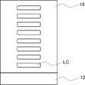
- FIG. 1 is a schematic view showing an example of an optical film.
- the optical film 10 has a resin base material 12 and an optically anisotropic layer 14 in this order. As shown in FIG. 1, the resin base material 12 and the optically anisotropic layer 14 are in direct contact with each other.
- each member constituting the optical film will be described in detail.
- the optical film has a resin base material.
- the resin base material has an orientation regulating force.
- the fact that the resin base material has an orientation regulating force means that the resin base material has a power to orient the liquid crystal compound when the liquid crystal compound is arranged on the surface of the resin base material. That is, the resin base material has an orientation regulating force for the liquid crystal compound.
- the resin base material having the orientation regulating force examples include a resin base material that has been subjected to a rubbing treatment and a resin base material that has been subjected to a stretching treatment, and a resin base material that has been subjected to a rubbing treatment is preferable. ..
- the direction of the rubbing treatment is not particularly limited, and the optimum direction is appropriately selected according to the direction in which the liquid crystal compound is desired to be oriented.
- a processing method widely adopted as a liquid crystal alignment processing step of an LCD (liquid crystal display) can be applied. That is, a method of obtaining orientation can be used by rubbing the surface of the resin base material in a certain direction with paper, gauze, felt, rubber, nylon fiber, polyester fiber, or the like.
- the transparent base material is intended to be a base material having a visible light transmittance of 60% or more, and the transmittance is preferably 80% or more, more preferably 90% or more.
- the resin constituting the resin base material a polymer having excellent optical performance transparency, mechanical strength, thermal stability, moisture shielding property, isotropic property and the like is preferable.
- the resin base material include a cellulose acylate film (for example, a cellulose triacetate film (refractive index 1.48), a cellulose diacetate film, a cellulose acetate butyrate film, a cellulose acetate propionate film), and a polyolefin film (for example, Polyethylene film and polypropylene film), polyester film (eg polyethylene terephthalate film and polyethylene naphthalate film), polyacrylic film (eg polymethylmethacrylate), polyethersulfone film, polyurethane film, polycarbonate film, polysulfone film, polyether film , Polymethylpentene film, polyether ketone film, (meth) acrylic nitrile film, and polymer film having an alicyclic structure (Norbornene resin (Arton: trade name, manufactured by JSR
- the adhesion between the resin base material and the optically anisotropic layer is more excellent, and the occurrence of optical defects in the optically anisotropic layer is further suppressed.
- Cellulose acylate, poly (meth) acrylate, polymer having an alicyclic structure, polystyrene, or in that the effect of at least one of the above can be obtained hereinafter, also simply referred to as "the point where the effect of the present invention is more excellent").
- Polycarbonate is preferred, and cellulose acylate is more preferred.
- the resin substrate contains various additives (for example, optical anisotropy adjuster, wavelength dispersion adjuster, fine particles, plasticizer, ultraviolet inhibitor, deterioration inhibitor, and release agent). May be good.
- additives for example, optical anisotropy adjuster, wavelength dispersion adjuster, fine particles, plasticizer, ultraviolet inhibitor, deterioration inhibitor, and release agent. May be good.
- the in-plane retardation of the resin base material at a wavelength of 550 nm is not particularly limited, but 10 nm or less is preferable in that the optical characteristics of the optically anisotropic layer can be more easily exhibited.
- the lower limit is not particularly limited, but 0 can be mentioned.
- SP (Solubility Parameter) value of the resin substrate is not particularly limited but is preferably 19.0 ⁇ 25.0 MPa 1/2, more preferably 20.0 ⁇ 23.0MPa 1/2.
- the SP value of the resin base material corresponds to the SP value of the resin constituting the resin base material.
- the sum is obtained by multiplying the squared value ( ⁇ d 2 , ⁇ p 2 , ⁇ h 2) of the three-dimensional SP value of each repeating unit by the body integration rate of each repeating unit.
- the squared value ( ⁇ d 2 , ⁇ p 2 , ⁇ h 2 ) of the three-dimensional SP value of the copolymer can be calculated and substituted into the above formula (X) to obtain the ⁇ a value of the copolymer.
- the thickness of the resin base material is not particularly limited, but is preferably 10 to 200 ⁇ m, more preferably 10 to 100 ⁇ m, and even more preferably 20 to 90 ⁇ m.
- the optically anisotropic layer contains a liquid crystal compound.
- the type of the liquid crystal compound is not particularly limited, and examples thereof include known liquid crystal compounds.
- the liquid crystal compound may be a low molecular weight compound or a high molecular weight compound.
- the low molecular weight compound means a compound having a molecular weight of 1000 or less
- the high molecular weight compound means a compound having a molecular weight of more than 1000.
- the liquid crystal compound contained in the optically anisotropic layer is preferably a polymer compound.
- the content of the liquid crystal compound in the optically anisotropic layer is not particularly limited, but is preferably 50% by mass or more, preferably 70% by mass or more, based on the total mass of the optically anisotropic layer in that the effect of the present invention is more excellent. Is more preferable.
- the upper limit is not particularly limited, but it is often 90% by mass or less.
- the optically anisotropic layer is preferably formed by using a composition containing a liquid crystal compound having a polymerizable group (hereinafter, also referred to as “polymerizable liquid crystal compound”). ..
- the liquid crystal compound contained in the optically anisotropic layer is preferably a polymer obtained by polymerizing a polymerizable liquid crystal compound.
- the type of the polymerizable liquid crystal compound is not particularly limited. In general, liquid crystal compounds can be classified into rod-shaped type (rod-shaped liquid crystal compound) and disk-shaped type (discotic liquid crystal compound) according to their shape. Further, the liquid crystal compound can be classified into a low molecular weight type and a high molecular weight type.
- a polymer generally refers to a polymer having a degree of polymerization of 100 or more (polymer physics / phase transition dynamics, by Masao Doi, p. 2, Iwanami Shoten, 1992).
- any liquid crystal compound can be used, but it is preferable to use a polymerizable rod-shaped liquid crystal compound or a polymerizable disk-shaped liquid crystal compound, and it is more preferable to use a polymerizable rod-shaped liquid crystal compound.
- Two or more kinds of polymerizable rod-shaped liquid crystal compounds, two or more kinds of polymerizable disk-shaped liquid crystal compounds, or a mixture of the polymerizable rod-shaped liquid crystal compound and the polymerizable disk-shaped liquid crystal compound may be used.
- polymerizable rod-shaped liquid crystal compound for example, those described in claim 1 of JP-A No. 11-513019 or paragraphs 0026 to 0098 of JP-A-2005-289980 can be preferably used.
- polymerizable disk-shaped liquid crystal compound for example, those described in paragraphs 0020 to 0067 of JP-A-2007-108732 or paragraphs 0013 to 0108 of JP-A-2010-2404038 can be preferably used.
- the type of the polymerizable group contained in the polymerizable liquid crystal compound is not particularly limited, and a functional group capable of an addition polymerization reaction is preferable, a polymerizable ethylenically unsaturated group or a ring-polymerizable group is more preferable, and an acryloyl group, a methacryloyl group, and the like.
- a vinyl group or a styryl group is more preferable.
- the optically anisotropic layer contains a compound having a hetero atom (specific compound), which is different from the liquid crystal compound described above. As will be described later, the specific compound is distributed at a predetermined position in the optical film.
- the specific compound has a heteroatom.
- the adhesion between the base material and the optically anisotropic layer is improved.
- the hetero atom an oxygen atom, a nitrogen atom, a sulfur atom, or a boron atom is preferable because the effect of the present invention is more excellent.
- the specific compound preferably has at least one selected from the group consisting of a urethane group, an ester group, an amide group, and a phenylboronic acid group in that the effect of the present invention is more excellent.
- the specific compound may be a low molecular weight compound or a high molecular weight compound.
- the low molecular weight compound means a compound having a molecular weight of 1000 or less
- the high molecular weight compound means a compound having a molecular weight of more than 1000.
- the specific compound contained in the optically anisotropic layer is preferably a polymer compound.
- the content of the specific compound in the optically anisotropic layer is not particularly limited, but is preferably 10% by mass or less, preferably 5% by mass or less, based on the total mass of the optically anisotropic layer in that the effect of the present invention is more excellent. Is more preferable, and 2% by mass or less is further preferable.
- the lower limit is not particularly limited, but is preferably 0.1% by mass or more, and more preferably 0.3% by mass or more.
- the optically anisotropic layer is preferably formed by using a composition containing a polymerizable compound having a heteroatom and a polymerizable group because the effect of the present invention is more excellent.
- the specific compound contained in the optically anisotropic layer is a polymer obtained by polymerizing a polymerizable compound having a heteroatom and a polymerizable group (hereinafter, also referred to as “specific polymerizable compound”). Is preferable.
- the specific polymerizable compound has a hetero atom.
- a hetero atom an oxygen atom, a nitrogen atom, a sulfur atom, or a boron atom is preferable because the effect of the present invention is more excellent.
- the specific polymerizable compound has at least one selected from the group consisting of a urethane group, an ester group, an amide group, and a phenylboronic acid group (-B (OH) 2) in that the effect of the present invention is more excellent. Is preferable.
- the specific polymerizable compound contains a repeating unit having a polymerizable group (hereinafter, also referred to as “unit 1”) and has a heteroatom in that the adhesion between the resin base material and the optically anisotropic layer is more excellent. It is preferably a polymer (hereinafter, also simply referred to as “specific polymerizable polymer”).
- the types of heteroatoms possessed by the specific polymerizable polymer are as described above.
- the specific polymerizable polymer preferably has at least one selected from the group consisting of a urethane group, an ester group, an amide group, and a phenylboronic acid group in that the effect of the present invention is more excellent. As will be described later, the specific polymerizable polymer may have a hetero atom in the unit 1.
- the type of the polymerizable group contained in the unit 1 is not particularly limited, a functional group capable of an addition polymerization reaction is preferable, a polymerizable ethylenically unsaturated group or a ring-polymerizable group is more preferable, and an acryloyl group, a methacryloyl group, and a vinyl group are preferable. , Or a styryl group is more preferred.
- the structure of the main chain of unit 1 is not particularly limited, and known structures can be mentioned, for example, (meth) acrylic skeleton, styrene skeleton, siloxane skeleton, cycloolefin skeleton, methylpentene skeleton, amide skeleton. , And a skeleton selected from the group consisting of aromatic ester-based skeletons is preferred. Of these, a skeleton selected from the group consisting of a (meth) acrylic skeleton, a siloxane skeleton, and a cycloolefin skeleton is more preferable, and a (meth) acrylic skeleton is even more preferable.
- the repeating unit represented by the formula (1) is preferable because the effect of the present invention is more excellent.
- R 1 represents a hydrogen atom or an alkyl group having 1 to 4 carbon atoms.
- L 1 represents a single bond or an n + 1 valent linking group.
- L 1 represents a divalent linking group
- L 1 represents a trivalent linking group.
- n represents 1.
- a divalent aliphatic hydrocarbon group for example, an alkylene group
- an arylene which may have a substituent
- Examples thereof include a group, a heteroarylene which may have a substituent, -O-, -CO-, -NH-, or a group in which two or more of these are combined.
- a divalent group which may have -CO-O-, -CO-NH-, -O-CO-NH-, and -CO-O- substituent may be used.
- Divalent aliphatic hydrocarbon group which may have an aliphatic hydrocarbon group-, -CO-NH- substituent-, a divalent aliphatic hydrocarbon which may have a -NH-substituted group.
- divalent aliphatic hydrocarbon group that may have a group-, -CO-O-substituted group-an arylene group that may have a substituent-, -CO-O-substituted group. May have divalent aliphatic hydrocarbon groups -O-, -CO-O- substituents may have divalent aliphatic hydrocarbon groups-NH-, -CO-O- substituents. Divalent aliphatic hydrocarbon group -O-CO-NH- which may have a divalent aliphatic hydrocarbon group which may have an -CO-O- substituent-O-CO- Examples thereof include a divalent aliphatic hydrocarbon group-O-which may have an NH-substituted group.
- the trivalent linking group examples include a trivalent aliphatic hydrocarbon group which may have a substituent, a trivalent aromatic group which may have a substituent, a nitrogen atom (> N-), and the like. Examples thereof include a group in which these groups and the above-mentioned divalent linking group are combined.
- L 1 preferably n + 1 valent linking group containing a hetero atom, more preferably a trivalent linking group containing a divalent linking group or a hetero atom containing a hetero atom, a urethane group, an ester group, and ,
- a divalent linking group containing at least one selected from the group consisting of amide groups is more preferred.
- the divalent linking group containing at least one selected from the group consisting of a urethane group, an ester group and an amide group includes at least one selected from the group consisting of a urethane group, an ester group and an amide group.
- a group in combination with an aliphatic hydrocarbon group is preferable, and examples thereof include a group exemplified in "a group in which two or more of these are combined" described in the above-mentioned divalent linking group.
- P 1 represents a polymerizable group.
- the definition of the polymerizable group is as described above.
- N represents an integer of 1 or more. Among them, 1 or 2 is preferable as n, and 1 is more preferable, from the viewpoint that the effect of the present invention is more excellent.
- the content of unit 1 in the specific polymerizable polymer is not particularly limited, but is preferably 20% by mass or more, preferably 50% by mass, based on all the repeating units of the specific polymerizable polymer in that the effect of the present invention is more excellent. % Or more is more preferable, and 70% by mass or more is further preferable.
- the upper limit is not particularly limited, but 100% by mass is mentioned, and in many cases, it is 95% by mass or less.
- Examples of the unit 1 include the repeating unit shown in Table 1 below.
- the specific polymerizable polymer may contain a repeating unit other than the unit 1 (hereinafter, also referred to as “unit 2”).
- the unit 2 is not particularly limited, but a repeating unit represented by the formula (2) can be mentioned because the effect of the present invention is more excellent.
- R 2 represents a hydrogen atom or an alkyl group having 1 to 4 carbon atoms.
- L 2 represents a single bond or a divalent linking group.
- Examples of the divalent linking group include the groups exemplified as the divalent linking group represented by L 1 described above.
- R 3 represents a hydrocarbon group which may have a substituent. Among them, an aliphatic hydrocarbon group or an aromatic hydrocarbon group (preferably a benzene ring), which may have a substituent, is preferable because the effect of the present invention is more excellent.
- the number of carbon atoms contained in the aliphatic hydrocarbon group is not particularly limited, but 1 to 20 is preferable, and 1 to 10 is more preferable.
- the aliphatic hydrocarbon group may be linear or branched.
- the aliphatic hydrocarbon group may have a cyclic structure.
- the substituent is not particularly limited, but for example, an alkyl group, an alkoxy group, an alkyl substituted alkoxy group, a cyclic alkyl group, an aryl group (for example, a phenyl group and a naphthyl group), a cyano group, an amino group, a nitro group, and an alkylcarbonyl.
- Examples include groups, sulfo groups, and hydroxyl groups.
- the content of unit 2 (for example, the repeating unit represented by the above formula (2)) is not particularly limited, but the specific polymerizable polymer can be used as all repeating units.
- 80% by mass or less is preferable, 50% by mass or less is more preferable, and 30% by mass or less is further preferable.
- the lower limit is not particularly limited, but may be 10% by mass or more.
- the weight average molecular weight of the specific polymerizable polymer is not particularly limited, but is preferably 5000 or more because the effect of the present invention is more excellent.
- the upper limit is not particularly limited, but 50,000 or less is preferable because the effect of the present invention is more excellent.
- the weight average molecular weight and the number average molecular weight in the present invention are values measured by a gel permeation chromatography (GPC) method under the conditions shown below.
- Equation (3) R 4- L 3- R 5 R 4 represents a polymerizable group.
- the definition of the polymerizable group is as described above.
- L 3 represents a single bond or a divalent linking group. Examples of the divalent linking group include the groups exemplified as the divalent linking group represented by L 1 described above.
- R 5 represents a boronic acid group or a hydroxy group.
- the absolute value of the difference between the SP value of the specific polymerizable compound and the SP value of the resin base material described above is not particularly limited, but 2.7 MPa 1/2 or less is preferable in that the effect of the present invention is more excellent. It is more preferably 0 MPa 1/2 or less.
- the lower limit is not particularly limited, but 0 can be mentioned.
- the optically anisotropic layer may contain components other than the liquid crystal compound and the specific compound described above. Examples of other components include other components (for example, chiral agents) that can be contained in the composition used for forming the optically anisotropic layer described later. Further, as will be described later, the optically anisotropic layer may contain a resin constituting a resin base material. In particular, the resin constituting the resin base material may be contained in the vicinity of the surface of the optically anisotropic layer on the resin base material side.
- the surface of the optical film on the optically anisotropic layer side is the first surface
- the surface of the optical film on the resin substrate side is the second surface
- the optical film of the present invention satisfies both the following requirements 1 and 2.
- Requirement 1 Derived from the resin constituting the resin base material, the depth position located on the second surface side showing the secondary ionic strength, which is 80% of the maximum strength of the secondary ionic strength derived from the liquid crystal compound, is set as the A position.
- the depth position located on the most first surface side showing the secondary ionic strength which is 80% of the maximum strength of the secondary ionic strength
- the maximum value Imax of the secondary ionic strength derived from the compound having a hetero atom is shown.
- Requirement 2 The peak position is the depth position showing the maximum value Imax of the secondary ionic strength derived from the compound having a hetero atom, and the peak position is on the first surface side of the peak position showing the secondary ionic strength of the maximum value Imax.
- the depth position closest to the peak position was defined as the C position, and the depth position closest to the peak position on the second surface side of the peak position, which shows the secondary ionic strength that is half of the maximum value Imax, was defined as the D position.
- the distance between the C position and the D position is 100 nm or less.
- FIG. 2 is an example of a profile obtained by analyzing the components in the depth direction in each layer by TOF-SIMS while ion-sputtering from the first surface 10A to the second surface 10B of the optically anisotropic layer of FIG. Shown.
- the depth direction is intended to be a direction toward the second surface with reference to the first surface of the optically anisotropic layer.
- the surface of the optical film 10 on the optically anisotropic layer 14 side is referred to as the first surface 10A
- the surface of the optical film 10 on the resin base material 12 side is referred to as the second surface 10B.
- the horizontal axis in FIG. 2, the axis extending in the left-right direction of the paper surface
- the vertical axis in FIG. 2.
- the axis extending in the vertical direction of the paper surface represents the secondary ionic strength of each component.
- the components in the depth direction of the optical film by TOF-SIMS while irradiating the ion beam after performing the component analysis in the surface depth region of 1 to 2 nm, the components are further analyzed in the depth direction from 1 nm to several hundreds. The series of operations of digging in nm and performing component analysis in the next surface depth region of 1 to 2 nm is repeated.
- the "secondary ionic strength derived from the liquid crystal compound" determined by the profile in the depth direction detected by analyzing the components in the depth direction of the optical film by TOF-SIMS is defined as the liquid crystal compound.
- the "secondary ionic strength derived from the resin” is intended to be the strength of the fragment ion derived from the resin constituting the resin base material, and is intended to be the “secondary ionic strength derived from a specific compound”. Means the intensity of fragment ions derived from a particular compound.
- the TOF-SIMS method is performed while irradiating an ion beam from the first surface 10A side to the second surface 10B side of the optical film 10 (toward the direction of the white arrow in FIG. 1).
- the secondary ion intensity derived from the liquid crystal compound in the optically anisotropic layer 14 is observed to be high, and when the ion beam is further irradiated in the depth direction, the liquid crystal is liquid crystal.
- the secondary ion intensity derived from the compound gradually decreases. This means that the optically anisotropic layer 14 is approaching the resin base material 12.
- the resin base material 12 is reached and the secondary ionic strength derived from the liquid crystal compound is not observed.
- the secondary ionic strength derived from the resin constituting the resin base material 12 is on the second surface 10B side. It increases as it goes toward.
- the resin base material 12 is reached, and the secondary ionic strength derived from the resin constituting the resin base material 12 becomes the highest.
- FIG. 2 the result of the secondary ionic strength derived from the specific compound (C3 in the figure) is shown.
- the secondary ion derived from the specific compound is strongly observed. More specifically, first, in the profile in the depth direction shown in FIG. 2, the depth located on the second surface side showing the secondary ionic strength which is 80% of the maximum strength of the secondary ionic strength derived from the liquid crystal compound.
- the position A is the position A, and the depth position located on the most first surface side showing the secondary ionic strength, which is 80% of the maximum strength of the secondary ionic strength derived from the resin constituting the resin base material, is the position B. ..
- the maximum intensity of the secondary ionic strength derived from the liquid crystal compound corresponds to M1
- the position close to the surface) is defined as the A position. Therefore, for example, when there are a plurality of depth positions showing 80% of the secondary ionic strength of M1, the depth position located closest to the second surface side is set as the A position. Further, in FIG.
- the closest position) is the B position. Therefore, for example, when there are a plurality of depth positions showing 80% of the secondary ionic strength of M2, the depth position located closest to the first surface side is set as the B position.
- a region between 50 nm from the first surface toward the second surface side hereinafter, also referred to as the first surface region.
- the secondary ionic strength of each component in the region between the second surface and the first surface side of 50 nm is the calculation of the maximum intensity described above. Do not take this into consideration. More specifically, the maximum intensity of the secondary ionic strength derived from the liquid crystal compound is defined in the region excluding the first surface region and the second surface region in the profile of the secondary ionic strength derived from the obtained liquid crystal compound. The maximum intensity of the secondary ionic strength derived from the liquid crystal compound is calculated as the maximum intensity.
- the maximum strength of the secondary ionic strength derived from the resin is the secondary ionic strength derived from the resin in the region excluding the first surface region and the second surface region in the profile of the secondary ionic strength derived from the obtained resin.
- the maximum strength of the strengths is calculated as the maximum strength.
- the maximum value Imax of the secondary ionic strength derived from the specific compound is shown at any depth position between the A position and the B position specified above.
- the maximum value Imax is shown at the peak position PP. That is, the maximum value Imax of the secondary ionic strength derived from the specific compound is observed between the A position and the B position.
- the specific compound is unevenly distributed on the resin substrate side in the tree optically anisotropic layer. By satisfying such requirement 1, the adhesion between the resin base material and the optically anisotropic layer becomes good.
- a peak showing the maximum value Imax is observed at the peak position PP located between the A position and the B position.
- the C position is a depth position located on the first surface side of the peak position and closest to the peak position, which shows a secondary ionic strength (Imax / 2) that is half of the maximum value Imax.
- the white arrow indicates the secondary ionic strength (Imax / 2), which is half of the maximum value Imax, when the depth position closest to the peak position on the second surface side of the peak position is the D position.
- the distance between the C position and the D position (hereinafter, also referred to as Iwid) is 100 nm or less. In the optical film satisfying the requirement 2, the amount of the specific compound unevenly distributed is not more than a predetermined amount.
- the Iwid becomes more than 100 nm.
- the orientation of the liquid crystal compound in the optically anisotropic layer is improved, and the occurrence of optical defects in the optically anisotropic layer is suppressed.
- the requirement 2 is not satisfied, the amount of the specific compound is too large, so that the orientation regulating force of the resin base material is weakened, and the orientation of the liquid crystal compound is deteriorated.
- the Iwid is preferably 50 nm or less in that the occurrence of optical defects in the optically anisotropic layer is further suppressed.
- the lower limit is not particularly limited, but it is often 1 nm or more, and more often 5 nm or more.
- the effect of the present invention is more excellent, when the average intensity of the secondary ionic strength derived from the specific compound from the first surface to the A position is set to the average value Iave, the maximum value Imax and the average value Iave are set. It is preferable to satisfy the relationship of the formula (A).
- Formula (A) 1.3 ⁇ Imax / Iave Among them, Imax / Iave is preferably 50 or more, more preferably 100 or more, in that the effect of the present invention is more excellent.
- the upper limit is not particularly limited, but Imax / Iave is often 1000 or less, and more often 500 or less.
- Ionic strength is not taken into account when calculating Iave as described above. More specifically, Iave is a 2 derived from a specific compound in the obtained profile of the secondary ionic strength derived from the specific compound in the region from the first surface to the A position excluding the first surface region. The average intensity of the next ionic strength.
- the method for producing the optical film of the present invention is not particularly limited, but a composition containing a polymerizable liquid crystal compound and a specific polymerizable compound (hereinafter, also simply referred to as “specific composition”” is obtained in that an optical film can be produced with high productivity.
- the method using) is preferable. More specifically, a specific composition is applied onto a resin base material having an orientation-regulating force to form a composition layer, the polymerizable liquid crystal compound in the composition layer is oriented, and then the polymerizable liquid crystal compound is formed.
- a method of producing an optical film having a resin base material and an optically anisotropic layer formed on the resin base material is preferable by immobilizing the orientation state of the above.
- the procedure of the above method will be described in detail.
- the resin base material having an orientation regulating force used in the above manufacturing method is as described above.
- the polymerizable liquid crystal compound and the specific polymerizable compound (preferably the specific polymerizable polymer) contained in the specific composition are as described above.
- the content of the polymerizable liquid crystal compound in the specific composition is not particularly limited, but is preferably 50% by mass or more, more preferably 70% by mass or more, based on the total solid content in the specific composition.
- the upper limit is not particularly limited, but it is often 90% by mass or less.
- the content of the specific polymerizable compound in the specific composition is preferably 10% by mass or less, more preferably 5% by mass or less, still more preferably 2% by mass or less, based on the total mass of the polymerizable liquid crystal compound.
- the lower limit is not particularly limited, but is preferably 0.1% by mass or more, and more preferably 0.3% by mass or more.
- the solid content means a component capable of forming an optically anisotropic layer from which the solvent in the specific composition has been removed, and is a solid content even if the property is liquid.
- the specific composition may contain components other than the above-mentioned polymerizable liquid crystal compound and the specific polymerizable compound.
- the specific composition may contain a solvent.
- the solvent include ester-based solvents, ether-based solvents, amide-based solvents, carbonate-based solvents, ketone-based solvents, aliphatic hydrocarbon-based solvents, alicyclic hydrocarbon-based solvents, aromatic hydrocarbon-based solvents, and halogenation.
- Examples include carbon-based solvents, water, and alcohol-based solvents. Of these, an ester solvent, an ether solvent, an amide solvent, a carbonate solvent, or a ketone solvent is preferable. Further, only one type of solvent may be used, or two or more types may be mixed and used.
- the specific composition may contain a polymerization initiator.
- the polymerization initiator include known polymerization initiators, photopolymerization initiators and thermal polymerization initiators, and photopolymerization initiators are preferable.
- the content of the polymerization initiator in the specific composition is not particularly limited, but is preferably 0.01 to 20% by mass, more preferably 0.5 to 10% by mass, based on the total solid content in the specific composition.
- the specific composition may contain a surfactant.
- the surfactant include conventionally known compounds, but fluorine-based compounds are preferable. Specifically, for example, the compounds described in paragraphs 0028 to 0056 of JP-A-2001-330725 and the compounds described in paragraphs 0069 to 0126 of JP-A-2005-062673 can be mentioned.
- the specific composition may include a polymer.
- the polymer include cellulose esters.
- examples of the cellulose ester include those described in paragraph 0178 in JP-A-2000-155216.
- the content of the polymer in the specific composition is not particularly limited, but is preferably 0.1 to 10% by mass, more preferably 0.1 to 8% by mass, based on the total mass of the polymerizable liquid crystal compound.
- the specific composition may contain an additive (orientation control agent) that promotes horizontal orientation or vertical orientation in order to bring the polymerizable liquid crystal compound into a horizontal or vertical orientation state.
- an additive orientation control agent
- the specific composition may further contain a chiral agent.
- the polymerizable liquid crystal compound can be twist-oriented along the spiral axis.
- the type of chiral auxiliary is not particularly limited. Use any of the known chiral agents (for example, "Liquid Crystal Device Handbook” edited by the 142nd Committee of the Japan Society for the Promotion of Science, Chapter 3, 4-3, TN, Chiral Auxiliary for STN, p. 199, 1989). Can be done.
- the spiral-inducing force (HTP) of the chiral agent is a factor indicating the spiral orientation ability represented by the following formula (X).
- Formula (X) HTP 1 / (length of spiral pitch (unit: ⁇ m) ⁇ concentration of chiral auxiliary to liquid crystal compound (mass%)) [ ⁇ m -1 ]
- the chiral agent may be a photosensitive chiral agent whose spiral-inducing force changes with light irradiation (hereinafter, also simply referred to as “chiral agent A”).
- the chiral agent A may be liquid crystal or non-liquid crystal.
- the chiral agent A generally contains an asymmetric carbon atom in many cases.
- the chiral agent A may be an axial asymmetric compound or a planar asymmetric compound that does not contain an asymmetric carbon atom.
- the chiral agent A may have a polymerizable group.
- the chiral agent A may be a chiral agent whose spiral-inducing force is increased or decreased by light irradiation. Of these, a chiral agent whose spiral inducing force is reduced by light irradiation is preferable.
- “increase and decrease of spiral-inducing force” means increase / decrease when the initial spiral direction (before light irradiation) of chiral agent A is "positive". Therefore, when the spiral inducing force continues to decrease due to light irradiation and the spiral direction becomes "negative" beyond 0 (that is, a spiral in the spiral direction opposite to the initial (before light irradiation) spiral direction is induced). (Case) also falls under the category of "chiral agent with reduced spiral inducing force".
- Examples of the chiral agent A include so-called photoreactive chiral agents.
- the photoreactive chiral agent is a compound having a chiral portion and a photoreactive portion whose structure is changed by light irradiation, and for example, the twisting force of the liquid crystal compound is significantly changed according to the irradiation amount.
- a compound having at least a photoisomerization site is preferable, and the photoisomerization site is more preferably having a photoisomerizable double bond.
- the photoisomerization site having a photoisomerizable double bond is a cinnamoyl site, a chalcone site, an azobenzene site or a azobenzene site in that photoisomerization is likely to occur and the difference in spiral-induced force before and after light irradiation is large.
- the stilbene moiety is preferred, and the cinnamoyl moiety, chalcone moiety or stilbene moiety is more preferred in that it absorbs less visible light.
- the photoisomerization site corresponds to the photoreaction site whose structure is changed by the above-mentioned light irradiation.
- the chiral agent A has one of a partial structure selected from a binaphthyl partial structure, an isosorbide partial structure (a partial structure derived from isosorbide), and an isomannide partial structure (a partial structure derived from isosorbide). Is preferable.
- the binaphthyl partial structure, the isosorbide partial structure, and the isosorbide partial structure are intended to have the following structures, respectively.
- the part of the binaphthyl substructure where the solid line and the broken line are parallel represents a single bond or a double bond. In the structure shown below, * represents the bonding position.
- the specific composition may contain two or more kinds of chiral auxiliary A, or a chiral agent whose spiral inducing force does not change by irradiation with at least one kind of chiral agent A and at least one kind of light (hereinafter, simply "chiral agent B"). It may also include.).
- the chiral agent B may be liquid crystal or non-liquid crystal.
- the chiral agent B generally contains an asymmetric carbon atom in many cases.
- the chiral agent B may be an axial asymmetric compound or a planar asymmetric compound that does not contain an asymmetric carbon atom.
- the chiral agent B may have a polymerizable group.
- As the chiral agent B a known chiral agent can be used.
- the chiral agent B is preferably a chiral agent that induces a spiral in the opposite direction to the above-mentioned chiral agent A. That is, for example, when the spiral induced by the chiral agent A is in the right direction, the spiral induced by the chiral agent B is in the left direction.
- the absolute value of the weighted average helical twisting power of the chiral agent is preferably 0.0 ⁇ 1.9 .mu.m -1, more preferably 0.0 ⁇ 1.5 ⁇ m -1, 0.0 ⁇ 1 . It is more preferably 0 ⁇ m -1 , particularly preferably 0.0 to 0.5 ⁇ m -1 , and most preferably zero.
- the absolute value of the weighted average spiral inducing force of the chiral auxiliary is in the above range, as will be described later, two or more layers having different optical characteristics along the thickness direction depending on the manufacturing conditions of the optically anisotropic layer. It is easy to form an optically anisotropic layer having.
- the weighted average spiral inducing force of the chiral auxiliary is the spiral inducing force of each chiral auxiliary and the concentration (mass) of each chiral agent with respect to the polymerizable liquid crystal compound when two or more kinds of chiral agents are contained in the specific composition. %) Divided by the total concentration (% by mass) of the chiral auxiliary with respect to the polymerizable liquid crystal compound.
- Y the following formula
- the spiral-inducing force is a negative value. That is, for example, if helical twisting power of the chiral agent of 10 [mu] m -1, when the spiral direction of the spiral, which is induced by the chiral agent is a right-handed represents a helical twisting power as 10 [mu] m -1. On the other hand, when the spiral direction of the spiral induced by the chiral agent is left-handed, the spiral-inducing force is expressed as -10 ⁇ m -1.
- the content of the chiral agent A in the specific composition is not particularly limited, but is preferably 5.0% by mass or less with respect to the total mass of the polymerizable liquid crystal compound in that the polymerizable liquid crystal compound is easily oriented uniformly. , 3.0% by mass or less is more preferable, and 2.0% by mass or less is further preferable.
- the lower limit is not particularly limited, but is preferably 0.01% by mass or more, and more preferably 0.02% by mass or more.
- the chiral auxiliary A may be used alone or in combination of two or more. When two or more of the above chiral agents A are used in combination, the total content is preferably within the above range.
- the content of the chiral agent B in the specific composition is not particularly limited, but is preferably 5.0% by mass or less with respect to the total mass of the polymerizable liquid crystal compound in that the polymerizable liquid crystal compound is easily oriented uniformly. , 3.0% by mass or less is more preferable, and 2.0% by mass or less is further preferable.
- the lower limit is not particularly limited, but is preferably 0.01% by mass or more, and more preferably 0.02% by mass or more.
- the chiral agent B may be used alone or in combination of two or more. When two or more of the above chiral agents B are used in combination, the total content is preferably within the above range.
- the total content of the chiral auxiliary (total content of all chiral agents) in the specific composition is preferably 5.0% by mass or less, preferably 4.0% by mass or less, based on the total mass of the polymerizable liquid crystal compound. More preferably, 2.0% by mass or less is even more preferable.
- the lower limit is not particularly limited, but is preferably 0.01% by mass or more, and more preferably 0.02% by mass or more.
- a specific composition is applied onto a resin base material to form a composition layer.
- the specific composition is applied directly onto the resin substrate.
- the specific composition is applied so that the surface of the resin base material is in contact with the specific composition.
- the coating method is not particularly limited, and examples thereof include a wire bar coating method, an extrusion coating method, a direct gravure coating method, a reverse gravure coating method, and a die coating method. If necessary, after the application of the specific composition, a treatment of drying the composition layer applied on the resin base material may be carried out. By carrying out a drying treatment, the solvent can be removed from the composition layer.
- the film thickness of the composition layer is not particularly limited, but is preferably 0.1 to 20 ⁇ m, more preferably 0.2 to 15 ⁇ m, and even more preferably 0.5 to 10 ⁇ m.
- the polymerizable liquid crystal compound in the composition layer is oriented.
- the treatment for orienting the polymerizable liquid crystal compound is not particularly limited, but heat treatment is preferable.
- the heat treatment conditions the optimum conditions are selected according to the polymerizable liquid crystal compound used.
- the heating temperature is often 10 to 250 ° C, more often 40 to 150 ° C, and even more often 50 to 130 ° C.
- the heating time is often 0.1 to 60 minutes, and more often 0.2 to 5 minutes.
- the orientation of the polymerizable liquid crystal compound depends on the material in the composition layer. Examples of the orientation state include homogenius orientation. When the composition layer contains a chiral agent, the polymerizable liquid crystal compound is twist-oriented along a spiral axis extending along the thickness direction of the composition layer.
- the orientation state of the polymerizable liquid crystal compound is fixed to form an optically anisotropic layer.
- the method for immobilizing the orientation state is not particularly limited, and the composition layer is subjected to a curing treatment to react the polymerizable groups in the polymerizable liquid crystal compound to form an optically anisotropic layer (cured layer). There is a way to do it.
- the method of curing treatment is not particularly limited, and examples thereof include photo-curing treatment and thermosetting treatment. Among them, the light irradiation treatment is preferable, and the ultraviolet irradiation treatment is more preferable.
- a light source such as an ultraviolet lamp is used for ultraviolet irradiation.
- the irradiation amount of light (for example, ultraviolet rays) is not particularly limited, but is generally preferably about 100 to 800 mJ / cm 2.
- the orientation state of the polymerizable liquid crystal compound is fixed.
- examples of the optically anisotropic layer include a layer formed by immobilizing a homogeneously oriented polymerizable liquid crystal compound.
- a layer formed by immobilizing a polymerizable liquid crystal compound twist-oriented having a spiral axis in the thickness direction can be mentioned.
- the "fixed” state means a state in which the orientation of the liquid crystal compound is maintained. It is not limited to that, and specifically, in the temperature range of 0 to 50 ° C., and more severely, -30 to 70 ° C., the layer has no fluidity, and is oriented by an external field or an external force. It is preferable that the fixed orientation form can be kept stable without causing a change. In the optically anisotropic layer, it is no longer necessary for the composition in the layer to finally exhibit liquid crystallinity.
- the optically anisotropic layer may have a single-layer structure or a multi-layer structure.
- the multi-layer structure means a structure in which two or more layers having different optical characteristics are laminated.
- steps A to E can be carried out to produce an optically anisotropic layer having two layers having different optical characteristics in one coating step. it can.
- Step A A specific composition containing a chiral agent A is applied onto a resin substrate to form a composition layer.
- Step B A heat treatment is applied to the composition layer to obtain a polymerizable liquid crystal compound in the composition layer.
- Step C After step B, the composition layer is irradiated with light under the condition of an oxygen concentration of 1% by volume or more.
- Step D After step C, the composition layer is heat-treated.
- step E After step D, the composition layer is cured to fix the orientation of the polymerizable liquid crystal compound and form an optically anisotropic layer. It will be described in detail.
- Step A Examples of the procedure of the step A include the above-mentioned procedure of applying the specific composition.
- the specific composition used in step A contains a chiral agent A in addition to the above-mentioned polymerizable liquid crystal compound and specific polymerizable compound.
- the specific composition may contain a chiral agent B.
- Step B The procedure of step B is not particularly limited, and examples thereof include a method of orienting the above-mentioned polymerizable liquid crystal compound.
- Step C Step C will be described below with reference to the drawings.
- the specific composition contains two types of chiral agents, chiral agent A and chiral agent B, and the absolute value of the weighted average spiral inducing force of the chiral agent in the composition layer formed by step A is 0. The case where is is typically described.
- the composition layer 16 in which the polymerizable liquid crystal compound LC is homogenically oriented is formed on the resin base material 12 by the step B.
- FIG. 3 is a schematic cross-sectional view of the resin base material 12 and the composition layer 16.
- step C the direction opposite to the composition layer 16 side of the resin base material 12 under the condition of an oxygen concentration of 1% by volume or more (the direction of the white arrow in FIG. 4). Light irradiation is performed from.
- the chiral agent A is also present in the lower region 16A, and the chiral agent A is also exposed to light, and the spiral inducing force changes.
- the orientation state of the polymerizable liquid crystal compound is fixed in the lower region 16A, the orientation of the liquid crystal compound is even if the step D of heat-treating the light-irradiated composition layer, which will be described later, is performed. There is no change in state.
- the oxygen concentration is high in the upper region 16B, even if light irradiation is performed, the polymerization of the polymerizable liquid crystal compound is inhibited by oxygen, and the polymerization is difficult to proceed.
- step D heat treatment
- step C the orientation state of the polymerizable liquid crystal compound is likely to be fixed in the region (lower region) of the composition layer on the resin substrate side. Further, in the region of the composition layer opposite to the resin base material side (upper region), the solidification of the oriented state of the polymerizable liquid crystal compound is difficult to proceed, and the spiral inducing force changes depending on the exposed chiral agent A. It will be in the state of.
- Step C is carried out under the condition that the oxygen concentration is 1% by volume or more.
- the oxygen concentration is preferably 2% by volume or more, more preferably 5% by volume or more, in that layers having different orientation states of the polymerizable liquid crystal compound are easily formed in the optically anisotropic layer.
- the upper limit is not particularly limited, but 100% by volume can be mentioned.
- the irradiation intensity of light irradiation in step C is not particularly limited and can be appropriately determined based on the spiral inducing force of the chiral agent A.
- the irradiation amount of light irradiation in the step C is not particularly limited, but is preferably 300 mJ / cm 2 or less, more preferably 200 mJ / cm 2 or less, in that a predetermined optically anisotropic layer is easily formed.
- the lower limit, in terms of easy predetermined optical anisotropic layer is formed is preferably 10 mJ / cm 2 or more, 30 mJ / cm 2 or more is more preferable.
- the light irradiation in step C is preferably carried out at 15 to 70 ° C. (preferably 15 to 50 ° C.).
- the light used for light irradiation may be the light that the chiral agent A is exposed to. That is, the light used for light irradiation is not particularly limited as long as it is an active ray or radiation that changes the spiral inducing force of the chiral agent A.
- the emission line spectrum of a mercury lamp far ultraviolet rays typified by an excimer laser, and poles. Examples include ultraviolet rays, X-rays, ultraviolet rays, and electron beams. Of these, ultraviolet rays are preferable.
- Step D is a step of heat-treating the composition layer after step C.
- the orientation state of the liquid crystal compound changes in the region where the spiral inducing force of the chiral auxiliary A in the composition layer subjected to light irradiation has changed.
- the orientation state of the polymerizable liquid crystal compound is fixed in the lower region 16A as shown in FIG.
- the polymerization of the polymerizable liquid crystal compound is difficult to proceed, and the orientation state of the polymerizable liquid crystal compound is not fixed.
- the spiral inducing force of the chiral agent A changes.
- the force for twisting the polymerizable liquid crystal compound changes in the upper region 16B as compared with the state before light irradiation. This point will be described in more detail.
- the chiral agent A and the chiral agent B are present in the composition layer 16 shown in FIG. 3 at the same concentration, the spiral direction induced by the chiral agent A is left-handed, and the chiral agent B causes the composition layer 16.
- the induced spiral direction is right-handed.
- the absolute value of the spiral-inducing force of the chiral agent A and the absolute value of the spiral-inducing force of the chiral agent B are the same. Therefore, the weighted average spiral inducing force of the chiral agent in the composition layer before light irradiation is 0.
- the vertical axis represents “the spiral inducing force of the chiral agent ( ⁇ m- 1 ) ⁇ the concentration of the chiral agent (mass%)”, and the farther the value is from zero, the greater the spiral inducing force.
- the horizontal axis represents "light irradiation amount (mJ / cm 2 )”.
- the relationship between the chiral agent A and the chiral agent B in the composition layer before light irradiation corresponds to the time when the light irradiation amount is 0, and "the spiral inducing force of the chiral auxiliary A ( ⁇ m- 1 ) ⁇ "
- the absolute value of "concentration of chiral auxiliary A (mass%)” and “spiral-inducing force of chiral agent B ( ⁇ m- 1 ) x concentration of chiral agent B (% by mass)” correspond to the same state. That is, the spiral-inducing forces of both the chiral agent A that induces left-handed winding and the chiral agent B that induces right-handed winding cancel each other out.
- the composition layer 16 after the step C in which such a change in the weighted average spiral inducing force is generated is heat-treated to promote the reorientation of the liquid crystal compound, as shown in FIG. 4, the upper side is shown.
- the polymerizable liquid crystal compound LC is twist-oriented along a spiral axis extending along the thickness direction of the composition layer 16.
- the polymerization of the polymerizable liquid crystal compound proceeds during step C and the orientation state of the polymerizable liquid crystal compound is fixed, so that the polymerizable liquid crystal compound is polymerizable. The reorientation of the liquid crystal compound does not proceed.
- step D by carrying out the step D, a plurality of regions having different orientation states of the polymerizable liquid crystal compound are formed along the thickness direction of the composition layer.
- the degree of twisting of the polymerizable liquid crystal compound LC can be appropriately adjusted depending on the type of chiral agent A used, the exposure amount in step C, and the like.
- the present invention is not limited to this embodiment.
- a chiral agent whose spiral inducing force is increased by light irradiation may be used as the chiral agent A.
- the spiral inducing force induced by the chiral agent A increases due to light irradiation, and the liquid crystal compound is twisted or oriented in the turning direction induced by the chiral auxiliary A.
- the mode in which the chiral agent A and the chiral agent B are used in combination has been described, but the mode is not limited to this mode.
- it may be an embodiment using two kinds of chiral agents A.
- the chiral agent A1 that induces left-handed winding and the chiral agent A2 that induces right-handed winding may be used in combination.
- the chiral agents A1 and A2 may be chiral agents whose spiral inducing force increases or chiral agents whose spiral inducing force decreases, respectively.
- a chiral agent that induces left-handed winding and whose spiral-inducing force increases by light irradiation and a chiral agent that induces right-handed winding and whose spiral-inducing force decreases by light irradiation are used in combination. You may.
- the optimum conditions are selected according to the liquid crystal compound used.
- the heating temperature is preferably a temperature for heating from the state of step C, often 35 to 250 ° C, more often 50 to 150 ° C, and more than 50 ° C and 150 ° C or less. Even more, especially at 60-130 ° C.
- the heating time is often 0.01 to 60 minutes, and more often 0.03 to 5 minutes.
- the absolute value of the weighted average spiral inducing force of the chiral agent in the composition layer after light irradiation is not particularly limited, but the weighted average spiral inducing force of the chiral agent in the composition layer after light irradiation and before light irradiation.
- the absolute value of the difference between the weighted average helical twisting power preferably 0.05 .mu.m -1 or more, more preferably 0.05 ⁇ 10.0 [mu] m -1, more preferably 0.1 ⁇ 10.0 [mu] m -1.
- the procedure of step E is not particularly limited, and examples thereof include the above-mentioned curing treatment.
- the optically anisotropic layer formed is a layer formed by fixing the orientation state of the homogeneously oriented polymerizable liquid crystal compound from the resin base material side. It includes two layers, one is a layer obtained by fixing the orientation state of the polymerizable liquid crystal compound twisted and oriented along a spiral axis extending along the thickness direction. That is, the formed optically anisotropic layer has a multi-layer structure.
- optical film can be applied to various uses, and examples thereof include an optical compensation film for optically compensating a liquid crystal cell and an antireflection film used in a display device such as an organic electroluminescence display device.
- the above-mentioned optical film may be used as a circular polarizing plate in combination with a polarizer.
- the polarizer may be a member having a function of converting natural light into specific linearly polarized light, and examples thereof include an absorption type polarizer.
- the type of the polarizer is not particularly limited, and a commonly used polarizer can be used, and examples thereof include an iodine-based polarizer, a dye-based polarizer using a dichroic dye, and a polyene-based polarizer.
- Iodine-based polarizers and dye-based polarizers are generally produced by adsorbing iodine or a dichroic dye on polyvinyl alcohol and stretching it.
- a protective film may be arranged on one side or both sides of the polarizer.
- the method for producing the circular polarizing plate is not particularly limited, and a known method can be adopted. For example, a method of adhering an optical film and a polarizer via an adhesive layer can be mentioned.
- the circularly polarizing plate can be suitably applied as an antireflection film for an organic EL display device.
- Example 1> Preparation of Cellulose Achillate Film (Substrate)
- the following components are put into a mixing tank, stirred, heated at 90 ° C. for 10 minutes, filtered through a filter paper having an average pore size of 34 ⁇ m and a sintered metal filter having an average pore size of 10 ⁇ m, and subjected to cellulose acylate dope (hereinafter, simply “” Also called “dope”) was manufactured.
- Cellulose acylate dope ⁇ Cellulose acylate (acetyl substitution degree 2.86, viscosity average degree of polymerization 310) 100 parts by mass sugar ester compound 1 (shown in chemical formula (S4)) 6.0 parts by mass sugar ester compound 2 (shown in chemical formula (S5)) 2.0 parts by mass silica particle dispersion (AEROSIL R972, Nippon Aerosil Co., Ltd.) Made) 0.1 parts by mass Solvent (methylene chloride / methanol / butanol) Predetermined amount ⁇
- the above-mentioned doping was cast using a drum film forming machine.
- the above-mentioned doping for forming the core layer so as to be in contact with the metal substrate cooled to 0 ° C. and the above-mentioned doping for forming the surface layer on the core layer were co-cast from the die, and then obtained.
- the film was peeled off.
- the drum was made of SUS (Steel Use Stainless).
- the film stripped from the drum was dried at 30-40 ° C. for 20 minutes during transport using a tenter device that clips and transports both ends of the film with clips.
- the obtained film was carried by roll and post-dried by zone heating. Then, the obtained film was knurled and then wound up.
- the film thickness of the obtained long cellulose acylate film was 40 ⁇ m
- the in-plane retardation Re (550) at a wavelength of 550 nm was 1 nm
- the retardation Rth (550) in the thickness direction at a wavelength of 550 nm was 26 nm, with an SP value.
- the cellulose acylate film produced above was continuously subjected to a rubbing treatment.
- the longitudinal direction of the long film and the conveying direction were parallel, and the angle formed by the film longitudinal direction (conveying direction) and the rotation axis of the rubbing roller was 72 °.
- the longitudinal direction of the film (conveyance direction) is 90 ° and the counterclockwise direction is represented by a positive value with respect to the width direction of the cellulose acylate film as a reference (0 °) when observed from the cellulose acylate film side, rubbing
- the axis of rotation of the roller was 18 °.
- the position of the rotation axis of the rubbing roller was a position rotated by 72 ° clockwise with reference to the longitudinal direction of the cellulose acylate film.
- composition (A) for forming an optically anisotropic layer containing the following rod-shaped liquid crystal compound is applied onto the rubbing-treated film using a Gieser coating machine, and the film on which the composition layer is formed is applied at 100 ° C. for 80 seconds. It was heated. Then, the composition layer was irradiated with the light of a 365 nm LED lamp (manufactured by Acroedge Co., Ltd.) at 40 ° C. under air (oxygen concentration: about 20% by volume) at an irradiation amount of 13 mJ / cm 2 . Further, the obtained composition layer was heated at 90 ° C. for 10 seconds.
- composition layer was irradiated with light from a metal halide lamp (manufactured by Eye Graphics Co., Ltd.) at 55 ° C. in a nitrogen atmosphere (irradiation amount: 500 mJ / cm 2 ) to fix the orientation of the liquid crystal compound.
- An optically anisotropic layer 1 was formed to prepare an optical film 1.
- composition of composition for forming an optically anisotropic layer (A) ⁇ ⁇
- the following polymerizable polymer (b-1) 0.5 parts by mass ⁇
- Rod-shaped liquid crystal compound (A) (hereinafter, corresponding to a mixture of liquid crystal compounds)
- Polymerizable polymer (b-1) (SP value: 23.2 MPa 1/2 ) (In the formula, the numerical value described in each repeating unit represents the content (mass%) of each repeating unit with respect to all repeating units).
- Polymer (A) (In the formula, the numerical value described in each repeating unit represents the content (mass%) of each repeating unit with respect to all repeating units.)
- Example 2 An optical film 2 was produced according to the same procedure as in Example 1 except that the polymer (b-1) was changed to the polymerizable polymer (b-2).
- Polymerizable polymer (b-2) (SP value: 23.7 MPa 1/2 ) (In the formula, the numerical value described in each repeating unit represents the content (mass%) of each repeating unit with respect to all repeating units).
- Example 3 An optical film 3 was produced according to the same procedure as in Example 1 except that the polymer (b-1) was changed to the polymerizable polymer (b-3).
- Polymerizable polymer (b-3) (SP value: 21.2 MPa 1/2 ) (In the formula, the numerical value described in each repeating unit represents the content (mass%) of each repeating unit with respect to all repeating units).
- Example 4 Same as Example 1 except that the cellulose acylate film was changed to a modified methyl methacrylate-based resin film (trade name "Finecast Film RZ-30NA-S" manufactured by Toyo Steel Sheet) (SP value: 20.5 MPa 1/2).
- the optical film 4 was produced according to the procedure of.
- Example 5 The optical film 5 was according to the same procedure as in Example 1 except that the cellulose acylate film was changed to a thermoplastic norbornene resin film (“Zeonoa” manufactured by Nippon Zeon Corporation) (SP value: 21 MPa 1/2). Was produced.
- Zeonoa thermoplastic norbornene resin film
- Example 6 An optical film 6 was produced according to the same procedure as in Example 1 except that the polymer (b-1) was changed to a boronic acid monomer (b-4).
- Cross-cut test A cross-cut test (a grid tape peeling test) based on JIS D0202-1988 was carried out on the optically anisotropic layer of the obtained optical film. Of the 100 squares formed by cutting in a grid pattern on the optically anisotropic layer, the number of squares peeled off by attaching and peeling cellophane tape (“CT24”, manufactured by Nichiban Co., Ltd.) is counted as follows. It was evaluated according to the criteria of.
- S The number of squares to be peeled is 0 "A”: The number of squares to be peeled is 1 to 30 "B”: The number of squares to be peeled is 31 to 50 "C”: The number of squares to be peeled is 51 or more
- the optical film of the present invention exhibited a desired effect. From the comparison of Examples 1, 4 and 5, it was confirmed that the effect was more excellent when the cellulose acylate film was used as the resin base material. From the comparison of Examples 1 to 3 and 6, it was confirmed that the effect was more excellent when the specific polymerizable polymer was used as the specific compound. From the comparison of Examples 1 to 3, it was confirmed that the effect was more excellent when Imax / Iave was 50 or more.
Landscapes
- Physics & Mathematics (AREA)
- Chemical & Material Sciences (AREA)
- General Physics & Mathematics (AREA)
- Optics & Photonics (AREA)
- Crystallography & Structural Chemistry (AREA)
- Nonlinear Science (AREA)
- Engineering & Computer Science (AREA)
- Organic Chemistry (AREA)
- Materials Engineering (AREA)
- Polymers & Plastics (AREA)
- Health & Medical Sciences (AREA)
- Chemical Kinetics & Catalysis (AREA)
- Medicinal Chemistry (AREA)
- Manufacturing & Machinery (AREA)
- Spectroscopy & Molecular Physics (AREA)
- Mathematical Physics (AREA)
- Analytical Chemistry (AREA)
- General Chemical & Material Sciences (AREA)
- Theoretical Computer Science (AREA)
- Polarising Elements (AREA)
- Liquid Crystal (AREA)
Abstract
Priority Applications (4)
| Application Number | Priority Date | Filing Date | Title |
|---|---|---|---|
| KR1020227004248A KR20220032586A (ko) | 2019-08-16 | 2020-08-14 | 광학 필름 |
| CN202080057702.7A CN114222937B (zh) | 2019-08-16 | 2020-08-14 | 光学膜 |
| JP2021540759A JP7376600B2 (ja) | 2019-08-16 | 2020-08-14 | 光学フィルム |
| US17/670,921 US11860338B2 (en) | 2019-08-16 | 2022-02-14 | Optical film |
Applications Claiming Priority (12)
| Application Number | Priority Date | Filing Date | Title |
|---|---|---|---|
| JP2019-149419 | 2019-08-16 | ||
| JP2019149419 | 2019-08-16 | ||
| JP2019175987 | 2019-09-26 | ||
| JP2019-175987 | 2019-09-26 | ||
| JP2019177831 | 2019-09-27 | ||
| JP2019-177831 | 2019-09-27 | ||
| JP2020095459 | 2020-06-01 | ||
| JP2020-095459 | 2020-06-01 | ||
| JP2020107171 | 2020-06-22 | ||
| JP2020-107171 | 2020-06-22 | ||
| JP2020132353 | 2020-08-04 | ||
| JP2020-132353 | 2020-08-04 |
Related Child Applications (1)
| Application Number | Title | Priority Date | Filing Date |
|---|---|---|---|
| US17/670,921 Continuation US11860338B2 (en) | 2019-08-16 | 2022-02-14 | Optical film |
Publications (1)
| Publication Number | Publication Date |
|---|---|
| WO2021033634A1 true WO2021033634A1 (fr) | 2021-02-25 |
Family
ID=74661130
Family Applications (1)
| Application Number | Title | Priority Date | Filing Date |
|---|---|---|---|
| PCT/JP2020/030863 WO2021033634A1 (fr) | 2019-08-16 | 2020-08-14 | Film optique |
Country Status (5)
| Country | Link |
|---|---|
| US (1) | US11860338B2 (fr) |
| JP (1) | JP7376600B2 (fr) |
| KR (1) | KR20220032586A (fr) |
| CN (1) | CN114222937B (fr) |
| WO (1) | WO2021033634A1 (fr) |
Cited By (1)
| Publication number | Priority date | Publication date | Assignee | Title |
|---|---|---|---|---|
| WO2021166802A1 (fr) * | 2020-02-18 | 2021-08-26 | 富士フイルム株式会社 | Composé et composition de cristaux liquides |
Families Citing this family (1)
| Publication number | Priority date | Publication date | Assignee | Title |
|---|---|---|---|---|
| JP7454597B2 (ja) * | 2020-02-06 | 2024-03-22 | 富士フイルム株式会社 | 光学フィルム、液晶フィルム |
Citations (4)
| Publication number | Priority date | Publication date | Assignee | Title |
|---|---|---|---|---|
| JP2011028026A (ja) * | 2009-07-27 | 2011-02-10 | Nitto Denko Corp | 光学積層体の製造方法 |
| WO2017164004A1 (fr) * | 2016-03-22 | 2017-09-28 | 富士フイルム株式会社 | Film optique, plaque de polarisation, dispositif d'affichage d'image, procédé de production de film optique et procédé de production de plaque de polarisation |
| WO2019009255A1 (fr) * | 2017-07-03 | 2019-01-10 | 富士フイルム株式会社 | Film de cristaux liquides, stratifié optique, plaque de polarisation circulaire et dispositif d'affichage électroluminescent organique |
| JP2020042149A (ja) * | 2018-09-10 | 2020-03-19 | 富士フイルム株式会社 | 液晶フィルム、光学積層体、円偏光板、および、有機エレクトロルミネッセンス表示装置 |
Family Cites Families (5)
| Publication number | Priority date | Publication date | Assignee | Title |
|---|---|---|---|---|
| US20080044596A1 (en) * | 2006-08-21 | 2008-02-21 | Fujifilm Corporation | Polymer film, production method thereof, and polarizing plate and liquid crystal display device using the polymer film |
| JP2014182217A (ja) | 2013-03-18 | 2014-09-29 | Fujifilm Corp | 光学フィルム材料 |
| JP6744418B2 (ja) | 2016-09-30 | 2020-08-19 | 富士フイルム株式会社 | 液晶組成物、光学フィルム、偏光板および画像表示装置 |
| WO2018174194A1 (fr) * | 2017-03-22 | 2018-09-27 | 富士フイルム株式会社 | Film optique, corps stratifié de film optique, plaque polarisante et dispositif d'affichage d'image |
| JP7293651B2 (ja) * | 2017-12-27 | 2023-06-20 | 大日本印刷株式会社 | 重合性液晶化合物、重合性組成物、重合体、位相差フィルム及びその製造方法、転写用積層体、光学部材及びその製造方法、並びに表示装置 |
-
2020
- 2020-08-14 KR KR1020227004248A patent/KR20220032586A/ko not_active Application Discontinuation
- 2020-08-14 WO PCT/JP2020/030863 patent/WO2021033634A1/fr active Application Filing
- 2020-08-14 CN CN202080057702.7A patent/CN114222937B/zh active Active
- 2020-08-14 JP JP2021540759A patent/JP7376600B2/ja active Active
-
2022
- 2022-02-14 US US17/670,921 patent/US11860338B2/en active Active
Patent Citations (4)
| Publication number | Priority date | Publication date | Assignee | Title |
|---|---|---|---|---|
| JP2011028026A (ja) * | 2009-07-27 | 2011-02-10 | Nitto Denko Corp | 光学積層体の製造方法 |
| WO2017164004A1 (fr) * | 2016-03-22 | 2017-09-28 | 富士フイルム株式会社 | Film optique, plaque de polarisation, dispositif d'affichage d'image, procédé de production de film optique et procédé de production de plaque de polarisation |
| WO2019009255A1 (fr) * | 2017-07-03 | 2019-01-10 | 富士フイルム株式会社 | Film de cristaux liquides, stratifié optique, plaque de polarisation circulaire et dispositif d'affichage électroluminescent organique |
| JP2020042149A (ja) * | 2018-09-10 | 2020-03-19 | 富士フイルム株式会社 | 液晶フィルム、光学積層体、円偏光板、および、有機エレクトロルミネッセンス表示装置 |
Cited By (2)
| Publication number | Priority date | Publication date | Assignee | Title |
|---|---|---|---|---|
| WO2021166802A1 (fr) * | 2020-02-18 | 2021-08-26 | 富士フイルム株式会社 | Composé et composition de cristaux liquides |
| JP7402306B2 (ja) | 2020-02-18 | 2023-12-20 | 富士フイルム株式会社 | 化合物、液晶組成物 |
Also Published As
| Publication number | Publication date |
|---|---|
| US20220171096A1 (en) | 2022-06-02 |
| CN114222937A (zh) | 2022-03-22 |
| KR20220032586A (ko) | 2022-03-15 |
| CN114222937B (zh) | 2024-02-06 |
| JP7376600B2 (ja) | 2023-11-08 |
| JPWO2021033634A1 (fr) | 2021-02-25 |
| US11860338B2 (en) | 2024-01-02 |
Similar Documents
| Publication | Publication Date | Title |
|---|---|---|
| JP4985550B2 (ja) | 位相差フィルム及びその製造方法、光学機能フィルム、偏光フィルム、並びに表示装置 | |
| US7527833B2 (en) | Biaxial film | |
| JP2015227947A (ja) | 積層体およびその製造方法、偏光板、液晶表示装置、有機el表示装置 | |
| WO2006002765A1 (fr) | Film biaxial a birefringence locale variant periodiquement | |
| WO2021033634A1 (fr) | Film optique | |
| KR20140138582A (ko) | 긴 패턴 배향막 및 그것을 사용한 긴 패턴 위상차 필름 | |
| WO2021182248A1 (fr) | Composition, procédé de production de film optique et film optique | |
| CN114222804B (zh) | 液晶组合物、光学膜、有机el显示器用圆偏振片、光学各向异性层的制造方法 | |
| CN114514451B (zh) | 光学膜、圆偏振片、有机电致发光显示装置 | |
| WO2016052404A1 (fr) | Film optique à couche de cristaux liquides cholestériques et procédé de production de film optique à couche de cristaux liquides cholestériques | |
| WO2021033631A1 (fr) | Procédé de production de couche anisotrope optique, procédé de production de stratifié, procédé de production de couche anisotrope optique équipée d'un polariseur, procédé de production de stratifié équipé d'un polariseur, composition et couche anisotrope optique | |
| WO2022054556A1 (fr) | Plaque de polarisation et dispositif d'affichage électroluminescent organique | |
| WO2022030308A1 (fr) | Couche optiquement anisotrope | |
| WO2021033639A1 (fr) | Procédé de production d'un film optique | |
| JP6045421B2 (ja) | 位相差フィルムの製造方法 | |
| WO2021132624A1 (fr) | Film optique, plaque de polarisation circulaire et dispositif d'affichage électroluminescent organique | |
| WO2022176884A1 (fr) | Procédé de production de film optique | |
| WO2022030218A1 (fr) | Couche optiquement anisotrope | |
| WO2022059569A1 (fr) | Film optique, plaque de polarisation circulaire et dispositif d'affichage électroluminescent organique | |
| WO2023276611A1 (fr) | Procédé de production d'une plaque de polarisation, procédé de production d'un dispositif d'affichage électroluminescent organique, plaque de polarisation, dispositif d'affichage électroluminescent organique et dispositif d'affichage à cristaux liquides | |
| CN116661045A (zh) | 层叠体、光学膜、偏振片及图像显示装置 |
Legal Events
| Date | Code | Title | Description |
|---|---|---|---|
| 121 | Ep: the epo has been informed by wipo that ep was designated in this application |
Ref document number: 20854352 Country of ref document: EP Kind code of ref document: A1 |
|
| ENP | Entry into the national phase |
Ref document number: 2021540759 Country of ref document: JP Kind code of ref document: A |
|
| ENP | Entry into the national phase |
Ref document number: 20227004248 Country of ref document: KR Kind code of ref document: A |
|
| NENP | Non-entry into the national phase |
Ref country code: DE |
|
| 122 | Ep: pct application non-entry in european phase |
Ref document number: 20854352 Country of ref document: EP Kind code of ref document: A1 |