WO2021033634A1 - Optical film - Google Patents
Optical film Download PDFInfo
- Publication number
- WO2021033634A1 WO2021033634A1 PCT/JP2020/030863 JP2020030863W WO2021033634A1 WO 2021033634 A1 WO2021033634 A1 WO 2021033634A1 JP 2020030863 W JP2020030863 W JP 2020030863W WO 2021033634 A1 WO2021033634 A1 WO 2021033634A1
- Authority
- WO
- WIPO (PCT)
- Prior art keywords
- liquid crystal
- optical film
- compound
- group
- crystal compound
- Prior art date
Links
- 239000012788 optical film Substances 0.000 title claims abstract description 79
- 150000001875 compounds Chemical class 0.000 claims abstract description 217
- 239000004973 liquid crystal related substance Substances 0.000 claims abstract description 148
- 239000011347 resin Substances 0.000 claims abstract description 105
- 229920005989 resin Polymers 0.000 claims abstract description 105
- 125000005842 heteroatom Chemical group 0.000 claims abstract description 33
- 239000000758 substrate Substances 0.000 claims abstract description 15
- 238000010884 ion-beam technique Methods 0.000 claims abstract description 8
- 239000000203 mixture Substances 0.000 claims description 97
- 239000000463 material Substances 0.000 claims description 77
- 239000010408 film Substances 0.000 claims description 48
- 229920000642 polymer Polymers 0.000 claims description 42
- 229920002678 cellulose Polymers 0.000 claims description 20
- 239000001913 cellulose Substances 0.000 claims description 18
- ODIGIKRIUKFKHP-UHFFFAOYSA-N (n-propan-2-yloxycarbonylanilino) acetate Chemical compound CC(C)OC(=O)N(OC(C)=O)C1=CC=CC=C1 ODIGIKRIUKFKHP-UHFFFAOYSA-N 0.000 claims description 17
- 125000003368 amide group Chemical group 0.000 claims description 8
- 125000004185 ester group Chemical group 0.000 claims description 8
- JOYRKODLDBILNP-UHFFFAOYSA-N urethane group Chemical group NC(=O)OCC JOYRKODLDBILNP-UHFFFAOYSA-N 0.000 claims description 8
- 230000001678 irradiating effect Effects 0.000 claims description 6
- 238000001004 secondary ion mass spectrometry Methods 0.000 claims description 4
- 125000005620 boronic acid group Chemical group 0.000 claims description 3
- 230000003287 optical effect Effects 0.000 abstract description 20
- 230000007547 defect Effects 0.000 abstract description 11
- 238000005011 time of flight secondary ion mass spectroscopy Methods 0.000 abstract description 9
- 238000002042 time-of-flight secondary ion mass spectrometry Methods 0.000 abstract description 9
- 239000010410 layer Substances 0.000 description 143
- UWCWUCKPEYNDNV-LBPRGKRZSA-N 2,6-dimethyl-n-[[(2s)-pyrrolidin-2-yl]methyl]aniline Chemical compound CC1=CC=CC(C)=C1NC[C@H]1NCCC1 UWCWUCKPEYNDNV-LBPRGKRZSA-N 0.000 description 104
- 230000001939 inductive effect Effects 0.000 description 53
- 238000000034 method Methods 0.000 description 36
- 230000000694 effects Effects 0.000 description 25
- 125000005647 linker group Chemical group 0.000 description 19
- 239000002904 solvent Substances 0.000 description 17
- 239000003795 chemical substances by application Substances 0.000 description 16
- 125000001931 aliphatic group Chemical group 0.000 description 13
- -1 Polyethylene Polymers 0.000 description 11
- 238000010438 heat treatment Methods 0.000 description 11
- QVGXLLKOCUKJST-UHFFFAOYSA-N atomic oxygen Chemical compound [O] QVGXLLKOCUKJST-UHFFFAOYSA-N 0.000 description 9
- 229910052760 oxygen Inorganic materials 0.000 description 9
- 239000001301 oxygen Substances 0.000 description 9
- 230000036961 partial effect Effects 0.000 description 9
- 125000001424 substituent group Chemical group 0.000 description 9
- 150000002500 ions Chemical class 0.000 description 8
- 238000006116 polymerization reaction Methods 0.000 description 8
- 230000001105 regulatory effect Effects 0.000 description 7
- YMWUJEATGCHHMB-UHFFFAOYSA-N Dichloromethane Chemical compound ClCCl YMWUJEATGCHHMB-UHFFFAOYSA-N 0.000 description 6
- OKKJLVBELUTLKV-UHFFFAOYSA-N Methanol Chemical compound OC OKKJLVBELUTLKV-UHFFFAOYSA-N 0.000 description 6
- 230000007423 decrease Effects 0.000 description 6
- 239000003505 polymerization initiator Substances 0.000 description 6
- 238000004804 winding Methods 0.000 description 6
- KLDXJTOLSGUMSJ-JGWLITMVSA-N Isosorbide Chemical compound O[C@@H]1CO[C@@H]2[C@@H](O)CO[C@@H]21 KLDXJTOLSGUMSJ-JGWLITMVSA-N 0.000 description 5
- NIXOWILDQLNWCW-UHFFFAOYSA-N acrylic acid group Chemical group C(C=C)(=O)O NIXOWILDQLNWCW-UHFFFAOYSA-N 0.000 description 5
- 229910052799 carbon Inorganic materials 0.000 description 5
- 230000008859 change Effects 0.000 description 5
- 229960002479 isosorbide Drugs 0.000 description 5
- 238000004519 manufacturing process Methods 0.000 description 5
- 238000007699 photoisomerization reaction Methods 0.000 description 5
- 239000007787 solid Substances 0.000 description 5
- LRHPLDYGYMQRHN-UHFFFAOYSA-N N-Butanol Chemical compound CCCCO LRHPLDYGYMQRHN-UHFFFAOYSA-N 0.000 description 4
- 150000001338 aliphatic hydrocarbons Chemical class 0.000 description 4
- 125000000217 alkyl group Chemical group 0.000 description 4
- 150000001721 carbon Chemical group 0.000 description 4
- 230000000052 comparative effect Effects 0.000 description 4
- 238000001723 curing Methods 0.000 description 4
- 230000003100 immobilizing effect Effects 0.000 description 4
- 150000002605 large molecules Chemical class 0.000 description 4
- 230000002829 reductive effect Effects 0.000 description 4
- 150000003384 small molecules Chemical class 0.000 description 4
- ZCYVEMRRCGMTRW-UHFFFAOYSA-N 7553-56-2 Chemical compound [I] ZCYVEMRRCGMTRW-UHFFFAOYSA-N 0.000 description 3
- UHOVQNZJYSORNB-UHFFFAOYSA-N Benzene Chemical group C1=CC=CC=C1 UHOVQNZJYSORNB-UHFFFAOYSA-N 0.000 description 3
- 239000004743 Polypropylene Substances 0.000 description 3
- 239000004793 Polystyrene Substances 0.000 description 3
- VYPSYNLAJGMNEJ-UHFFFAOYSA-N Silicium dioxide Chemical compound O=[Si]=O VYPSYNLAJGMNEJ-UHFFFAOYSA-N 0.000 description 3
- 150000001408 amides Chemical group 0.000 description 3
- 238000004458 analytical method Methods 0.000 description 3
- ZDZHCHYQNPQSGG-UHFFFAOYSA-N binaphthyl group Chemical group C1(=CC=CC2=CC=CC=C12)C1=CC=CC2=CC=CC=C12 ZDZHCHYQNPQSGG-UHFFFAOYSA-N 0.000 description 3
- 125000004432 carbon atom Chemical group C* 0.000 description 3
- 238000000576 coating method Methods 0.000 description 3
- 229920001577 copolymer Polymers 0.000 description 3
- 238000010894 electron beam technology Methods 0.000 description 3
- 239000003999 initiator Substances 0.000 description 3
- 229910052740 iodine Inorganic materials 0.000 description 3
- 239000011630 iodine Substances 0.000 description 3
- 229910052757 nitrogen Inorganic materials 0.000 description 3
- 125000004433 nitrogen atom Chemical group N* 0.000 description 3
- HXITXNWTGFUOAU-UHFFFAOYSA-N phenylboronic acid Chemical group OB(O)C1=CC=CC=C1 HXITXNWTGFUOAU-UHFFFAOYSA-N 0.000 description 3
- 229920002223 polystyrene Polymers 0.000 description 3
- 239000000126 substance Substances 0.000 description 3
- 238000012360 testing method Methods 0.000 description 3
- HRPVXLWXLXDGHG-UHFFFAOYSA-N Acrylamide Chemical group NC(=O)C=C HRPVXLWXLXDGHG-UHFFFAOYSA-N 0.000 description 2
- NIXOWILDQLNWCW-UHFFFAOYSA-M Acrylate Chemical compound [O-]C(=O)C=C NIXOWILDQLNWCW-UHFFFAOYSA-M 0.000 description 2
- 229910002012 Aerosil® Inorganic materials 0.000 description 2
- ZOXJGFHDIHLPTG-UHFFFAOYSA-N Boron Chemical group [B] ZOXJGFHDIHLPTG-UHFFFAOYSA-N 0.000 description 2
- RTZKZFJDLAIYFH-UHFFFAOYSA-N Diethyl ether Chemical compound CCOCC RTZKZFJDLAIYFH-UHFFFAOYSA-N 0.000 description 2
- 125000003647 acryloyl group Chemical group O=C([*])C([H])=C([H])[H] 0.000 description 2
- 238000012644 addition polymerization Methods 0.000 description 2
- 239000000654 additive Substances 0.000 description 2
- 125000002723 alicyclic group Chemical group 0.000 description 2
- 125000003118 aryl group Chemical group 0.000 description 2
- 125000000732 arylene group Chemical group 0.000 description 2
- DMLAVOWQYNRWNQ-UHFFFAOYSA-N azobenzene Chemical compound C1=CC=CC=C1N=NC1=CC=CC=C1 DMLAVOWQYNRWNQ-UHFFFAOYSA-N 0.000 description 2
- 229910052796 boron Inorganic materials 0.000 description 2
- ZADPBFCGQRWHPN-UHFFFAOYSA-N boronic acid Chemical compound OBO ZADPBFCGQRWHPN-UHFFFAOYSA-N 0.000 description 2
- 238000011088 calibration curve Methods 0.000 description 2
- 238000006243 chemical reaction Methods 0.000 description 2
- 239000011248 coating agent Substances 0.000 description 2
- 239000012792 core layer Substances 0.000 description 2
- 150000001925 cycloalkenes Chemical group 0.000 description 2
- 238000010586 diagram Methods 0.000 description 2
- 239000006185 dispersion Substances 0.000 description 2
- 238000001035 drying Methods 0.000 description 2
- 150000002148 esters Chemical class 0.000 description 2
- FKRCODPIKNYEAC-UHFFFAOYSA-N ethyl propionate Chemical compound CCOC(=O)CC FKRCODPIKNYEAC-UHFFFAOYSA-N 0.000 description 2
- 239000012634 fragment Substances 0.000 description 2
- 125000000524 functional group Chemical group 0.000 description 2
- 238000005227 gel permeation chromatography Methods 0.000 description 2
- 238000007756 gravure coating Methods 0.000 description 2
- 125000004435 hydrogen atom Chemical group [H]* 0.000 description 2
- 125000002887 hydroxy group Chemical group [H]O* 0.000 description 2
- 230000006872 improvement Effects 0.000 description 2
- 239000003112 inhibitor Substances 0.000 description 2
- 239000011254 layer-forming composition Substances 0.000 description 2
- 239000007788 liquid Substances 0.000 description 2
- 238000005259 measurement Methods 0.000 description 2
- QSHDDOUJBYECFT-UHFFFAOYSA-N mercury Chemical compound [Hg] QSHDDOUJBYECFT-UHFFFAOYSA-N 0.000 description 2
- 229910052753 mercury Inorganic materials 0.000 description 2
- 229910052751 metal Inorganic materials 0.000 description 2
- 239000002184 metal Substances 0.000 description 2
- 239000000178 monomer Substances 0.000 description 2
- JFNLZVQOOSMTJK-KNVOCYPGSA-N norbornene Chemical compound C1[C@@H]2CC[C@H]1C=C2 JFNLZVQOOSMTJK-KNVOCYPGSA-N 0.000 description 2
- 125000004430 oxygen atom Chemical group O* 0.000 description 2
- 229920003229 poly(methyl methacrylate) Polymers 0.000 description 2
- 239000004417 polycarbonate Substances 0.000 description 2
- 229920000515 polycarbonate Polymers 0.000 description 2
- 230000000379 polymerizing effect Effects 0.000 description 2
- 239000004926 polymethyl methacrylate Substances 0.000 description 2
- 229920000098 polyolefin Polymers 0.000 description 2
- 239000011148 porous material Substances 0.000 description 2
- 230000008569 process Effects 0.000 description 2
- 230000005855 radiation Effects 0.000 description 2
- 238000001228 spectrum Methods 0.000 description 2
- 238000004544 sputter deposition Methods 0.000 description 2
- PJANXHGTPQOBST-UHFFFAOYSA-N stilbene Chemical group C=1C=CC=CC=1C=CC1=CC=CC=C1 PJANXHGTPQOBST-UHFFFAOYSA-N 0.000 description 2
- 125000005504 styryl group Chemical group 0.000 description 2
- 229910052717 sulfur Inorganic materials 0.000 description 2
- 125000004434 sulfur atom Chemical group 0.000 description 2
- 239000004094 surface-active agent Substances 0.000 description 2
- DQFBYFPFKXHELB-VAWYXSNFSA-N trans-chalcone Chemical compound C=1C=CC=CC=1C(=O)\C=C\C1=CC=CC=C1 DQFBYFPFKXHELB-VAWYXSNFSA-N 0.000 description 2
- 238000002834 transmittance Methods 0.000 description 2
- 230000032258 transport Effects 0.000 description 2
- 125000000391 vinyl group Chemical group [H]C([*])=C([H])[H] 0.000 description 2
- KLDXJTOLSGUMSJ-BXKVDMCESA-N (3s,3as,6s,6as)-2,3,3a,5,6,6a-hexahydrofuro[3,2-b]furan-3,6-diol Chemical compound O[C@H]1CO[C@H]2[C@@H](O)CO[C@H]21 KLDXJTOLSGUMSJ-BXKVDMCESA-N 0.000 description 1
- OKTJSMMVPCPJKN-UHFFFAOYSA-N Carbon Chemical compound [C] OKTJSMMVPCPJKN-UHFFFAOYSA-N 0.000 description 1
- 239000004215 Carbon black (E152) Substances 0.000 description 1
- BVKZGUZCCUSVTD-UHFFFAOYSA-L Carbonate Chemical compound [O-]C([O-])=O BVKZGUZCCUSVTD-UHFFFAOYSA-L 0.000 description 1
- 229920000298 Cellophane Polymers 0.000 description 1
- 229920008347 Cellulose acetate propionate Polymers 0.000 description 1
- 229920001747 Cellulose diacetate Polymers 0.000 description 1
- 229920002284 Cellulose triacetate Polymers 0.000 description 1
- DQFBYFPFKXHELB-UHFFFAOYSA-N Chalcone Natural products C=1C=CC=CC=1C(=O)C=CC1=CC=CC=C1 DQFBYFPFKXHELB-UHFFFAOYSA-N 0.000 description 1
- 239000004986 Cholesteric liquid crystals (ChLC) Substances 0.000 description 1
- 229920000089 Cyclic olefin copolymer Polymers 0.000 description 1
- 239000004985 Discotic Liquid Crystal Substance Substances 0.000 description 1
- VGGSQFUCUMXWEO-UHFFFAOYSA-N Ethene Chemical compound C=C VGGSQFUCUMXWEO-UHFFFAOYSA-N 0.000 description 1
- 239000005977 Ethylene Substances 0.000 description 1
- YCKRFDGAMUMZLT-UHFFFAOYSA-N Fluorine atom Chemical compound [F] YCKRFDGAMUMZLT-UHFFFAOYSA-N 0.000 description 1
- DGAQECJNVWCQMB-PUAWFVPOSA-M Ilexoside XXIX Chemical compound C[C@@H]1CC[C@@]2(CC[C@@]3(C(=CC[C@H]4[C@]3(CC[C@@H]5[C@@]4(CC[C@@H](C5(C)C)OS(=O)(=O)[O-])C)C)[C@@H]2[C@]1(C)O)C)C(=O)O[C@H]6[C@@H]([C@H]([C@@H]([C@H](O6)CO)O)O)O.[Na+] DGAQECJNVWCQMB-PUAWFVPOSA-M 0.000 description 1
- CERQOIWHTDAKMF-UHFFFAOYSA-M Methacrylate Chemical compound CC(=C)C([O-])=O CERQOIWHTDAKMF-UHFFFAOYSA-M 0.000 description 1
- NTIZESTWPVYFNL-UHFFFAOYSA-N Methyl isobutyl ketone Chemical compound CC(C)CC(C)=O NTIZESTWPVYFNL-UHFFFAOYSA-N 0.000 description 1
- UIHCLUNTQKBZGK-UHFFFAOYSA-N Methyl isobutyl ketone Natural products CCC(C)C(C)=O UIHCLUNTQKBZGK-UHFFFAOYSA-N 0.000 description 1
- VVQNEPGJFQJSBK-UHFFFAOYSA-N Methyl methacrylate Chemical class COC(=O)C(C)=C VVQNEPGJFQJSBK-UHFFFAOYSA-N 0.000 description 1
- 239000004695 Polyether sulfone Substances 0.000 description 1
- 239000004698 Polyethylene Substances 0.000 description 1
- 239000004721 Polyphenylene oxide Substances 0.000 description 1
- 239000004372 Polyvinyl alcohol Substances 0.000 description 1
- 229910000831 Steel Inorganic materials 0.000 description 1
- WYURNTSHIVDZCO-UHFFFAOYSA-N Tetrahydrofuran Chemical compound C1CCOC1 WYURNTSHIVDZCO-UHFFFAOYSA-N 0.000 description 1
- NNLVGZFZQQXQNW-ADJNRHBOSA-N [(2r,3r,4s,5r,6s)-4,5-diacetyloxy-3-[(2s,3r,4s,5r,6r)-3,4,5-triacetyloxy-6-(acetyloxymethyl)oxan-2-yl]oxy-6-[(2r,3r,4s,5r,6s)-4,5,6-triacetyloxy-2-(acetyloxymethyl)oxan-3-yl]oxyoxan-2-yl]methyl acetate Chemical compound O([C@@H]1O[C@@H]([C@H]([C@H](OC(C)=O)[C@H]1OC(C)=O)O[C@H]1[C@@H]([C@@H](OC(C)=O)[C@H](OC(C)=O)[C@@H](COC(C)=O)O1)OC(C)=O)COC(=O)C)[C@@H]1[C@@H](COC(C)=O)O[C@@H](OC(C)=O)[C@H](OC(C)=O)[C@H]1OC(C)=O NNLVGZFZQQXQNW-ADJNRHBOSA-N 0.000 description 1
- 238000010521 absorption reaction Methods 0.000 description 1
- 125000000218 acetic acid group Chemical group C(C)(=O)* 0.000 description 1
- 230000000996 additive effect Effects 0.000 description 1
- 239000012790 adhesive layer Substances 0.000 description 1
- 239000005456 alcohol based solvent Substances 0.000 description 1
- 125000003545 alkoxy group Chemical group 0.000 description 1
- 125000004448 alkyl carbonyl group Chemical group 0.000 description 1
- 125000002947 alkylene group Chemical group 0.000 description 1
- 125000003277 amino group Chemical group 0.000 description 1
- 125000002029 aromatic hydrocarbon group Chemical group 0.000 description 1
- 150000004945 aromatic hydrocarbons Chemical class 0.000 description 1
- 238000007611 bar coating method Methods 0.000 description 1
- 230000015572 biosynthetic process Effects 0.000 description 1
- 238000004364 calculation method Methods 0.000 description 1
- 239000003660 carbonate based solvent Substances 0.000 description 1
- 229920006265 cellulose acetate-butyrate film Polymers 0.000 description 1
- 235000005513 chalcones Nutrition 0.000 description 1
- 229940125904 compound 1 Drugs 0.000 description 1
- 229940125782 compound 2 Drugs 0.000 description 1
- 210000002858 crystal cell Anatomy 0.000 description 1
- 238000005520 cutting process Methods 0.000 description 1
- 125000004093 cyano group Chemical group *C#N 0.000 description 1
- 125000006165 cyclic alkyl group Chemical group 0.000 description 1
- 125000004122 cyclic group Chemical group 0.000 description 1
- 230000003247 decreasing effect Effects 0.000 description 1
- 230000006866 deterioration Effects 0.000 description 1
- 238000007607 die coating method Methods 0.000 description 1
- HBGGXOJOCNVPFY-UHFFFAOYSA-N diisononyl phthalate Chemical compound CC(C)CCCCCCOC(=O)C1=CC=CC=C1C(=O)OCCCCCCC(C)C HBGGXOJOCNVPFY-UHFFFAOYSA-N 0.000 description 1
- 238000009826 distribution Methods 0.000 description 1
- 229920001971 elastomer Polymers 0.000 description 1
- 238000005401 electroluminescence Methods 0.000 description 1
- 239000003480 eluent Substances 0.000 description 1
- 238000005516 engineering process Methods 0.000 description 1
- 239000003759 ester based solvent Substances 0.000 description 1
- 239000004210 ether based solvent Substances 0.000 description 1
- JBTWLSYIZRCDFO-UHFFFAOYSA-N ethyl methyl carbonate Chemical compound CCOC(=O)OC JBTWLSYIZRCDFO-UHFFFAOYSA-N 0.000 description 1
- 238000011156 evaluation Methods 0.000 description 1
- 238000007765 extrusion coating Methods 0.000 description 1
- 239000000835 fiber Substances 0.000 description 1
- 239000010419 fine particle Substances 0.000 description 1
- 229910052731 fluorine Inorganic materials 0.000 description 1
- 239000011737 fluorine Substances 0.000 description 1
- 230000026030 halogenation Effects 0.000 description 1
- 238000005658 halogenation reaction Methods 0.000 description 1
- 125000005549 heteroarylene group Chemical group 0.000 description 1
- RYPKRALMXUUNKS-UHFFFAOYSA-N hex-2-ene Chemical group CCCC=CC RYPKRALMXUUNKS-UHFFFAOYSA-N 0.000 description 1
- 229930195733 hydrocarbon Natural products 0.000 description 1
- 150000002430 hydrocarbons Chemical group 0.000 description 1
- 230000006698 induction Effects 0.000 description 1
- 239000004615 ingredient Substances 0.000 description 1
- 230000010354 integration Effects 0.000 description 1
- 239000005453 ketone based solvent Substances 0.000 description 1
- 150000002576 ketones Chemical class 0.000 description 1
- 238000000691 measurement method Methods 0.000 description 1
- 230000007246 mechanism Effects 0.000 description 1
- 229910001507 metal halide Inorganic materials 0.000 description 1
- 150000005309 metal halides Chemical class 0.000 description 1
- 125000005395 methacrylic acid group Chemical group 0.000 description 1
- 238000002156 mixing Methods 0.000 description 1
- 125000001624 naphthyl group Chemical group 0.000 description 1
- 125000000449 nitro group Chemical group [O-][N+](*)=O 0.000 description 1
- 239000012299 nitrogen atmosphere Substances 0.000 description 1
- 229920001778 nylon Polymers 0.000 description 1
- 239000002245 particle Substances 0.000 description 1
- 125000001997 phenyl group Chemical group [H]C1=C([H])C([H])=C(*)C([H])=C1[H] 0.000 description 1
- 238000000016 photochemical curing Methods 0.000 description 1
- 239000004014 plasticizer Substances 0.000 description 1
- 229920001643 poly(ether ketone) Polymers 0.000 description 1
- 229920002492 poly(sulfone) Polymers 0.000 description 1
- 229920006289 polycarbonate film Polymers 0.000 description 1
- 150000004291 polyenes Chemical class 0.000 description 1
- 229920000728 polyester Polymers 0.000 description 1
- 229920006267 polyester film Polymers 0.000 description 1
- 229920000570 polyether Polymers 0.000 description 1
- 229920006393 polyether sulfone Polymers 0.000 description 1
- 229920000573 polyethylene Polymers 0.000 description 1
- 229920006290 polyethylene naphthalate film Polymers 0.000 description 1
- 229920000139 polyethylene terephthalate Polymers 0.000 description 1
- 239000005020 polyethylene terephthalate Substances 0.000 description 1
- 229920006254 polymer film Polymers 0.000 description 1
- 229920000193 polymethacrylate Polymers 0.000 description 1
- 239000011116 polymethylpentene Substances 0.000 description 1
- 229920000306 polymethylpentene Polymers 0.000 description 1
- 229920001155 polypropylene Polymers 0.000 description 1
- 229920006264 polyurethane film Polymers 0.000 description 1
- 229920002451 polyvinyl alcohol Polymers 0.000 description 1
- 238000002360 preparation method Methods 0.000 description 1
- 238000012545 processing Methods 0.000 description 1
- 238000003672 processing method Methods 0.000 description 1
- 230000001681 protective effect Effects 0.000 description 1
- 230000002441 reversible effect Effects 0.000 description 1
- 239000000377 silicon dioxide Substances 0.000 description 1
- 239000002356 single layer Substances 0.000 description 1
- 229910052708 sodium Inorganic materials 0.000 description 1
- 239000011734 sodium Substances 0.000 description 1
- 238000007711 solidification Methods 0.000 description 1
- 230000008023 solidification Effects 0.000 description 1
- 239000010959 steel Substances 0.000 description 1
- 125000003011 styrenyl group Chemical group [H]\C(*)=C(/[H])C1=C([H])C([H])=C([H])C([H])=C1[H] 0.000 description 1
- 125000005415 substituted alkoxy group Chemical group 0.000 description 1
- 238000006467 substitution reaction Methods 0.000 description 1
- 125000000020 sulfo group Chemical group O=S(=O)([*])O[H] 0.000 description 1
- 238000005211 surface analysis Methods 0.000 description 1
- 239000002344 surface layer Substances 0.000 description 1
- 238000012719 thermal polymerization Methods 0.000 description 1
- 229920001169 thermoplastic Polymers 0.000 description 1
- 229920001187 thermosetting polymer Polymers 0.000 description 1
- 239000004416 thermosoftening plastic Substances 0.000 description 1
- 230000007704 transition Effects 0.000 description 1
- XLYOFNOQVPJJNP-UHFFFAOYSA-N water Substances O XLYOFNOQVPJJNP-UHFFFAOYSA-N 0.000 description 1
Images


Classifications
-
- C—CHEMISTRY; METALLURGY
- C09—DYES; PAINTS; POLISHES; NATURAL RESINS; ADHESIVES; COMPOSITIONS NOT OTHERWISE PROVIDED FOR; APPLICATIONS OF MATERIALS NOT OTHERWISE PROVIDED FOR
- C09K—MATERIALS FOR MISCELLANEOUS APPLICATIONS, NOT PROVIDED FOR ELSEWHERE
- C09K19/00—Liquid crystal materials
- C09K19/52—Liquid crystal materials characterised by components which are not liquid crystals, e.g. additives with special physical aspect: solvents, solid particles
- C09K19/58—Dopants or charge transfer agents
- C09K19/586—Optically active dopants; chiral dopants
-
- C—CHEMISTRY; METALLURGY
- C08—ORGANIC MACROMOLECULAR COMPOUNDS; THEIR PREPARATION OR CHEMICAL WORKING-UP; COMPOSITIONS BASED THEREON
- C08J—WORKING-UP; GENERAL PROCESSES OF COMPOUNDING; AFTER-TREATMENT NOT COVERED BY SUBCLASSES C08B, C08C, C08F, C08G or C08H
- C08J5/00—Manufacture of articles or shaped materials containing macromolecular substances
- C08J5/18—Manufacture of films or sheets
-
- C—CHEMISTRY; METALLURGY
- C08—ORGANIC MACROMOLECULAR COMPOUNDS; THEIR PREPARATION OR CHEMICAL WORKING-UP; COMPOSITIONS BASED THEREON
- C08J—WORKING-UP; GENERAL PROCESSES OF COMPOUNDING; AFTER-TREATMENT NOT COVERED BY SUBCLASSES C08B, C08C, C08F, C08G or C08H
- C08J7/00—Chemical treatment or coating of shaped articles made of macromolecular substances
- C08J7/12—Chemical modification
- C08J7/16—Chemical modification with polymerisable compounds
-
- C—CHEMISTRY; METALLURGY
- C09—DYES; PAINTS; POLISHES; NATURAL RESINS; ADHESIVES; COMPOSITIONS NOT OTHERWISE PROVIDED FOR; APPLICATIONS OF MATERIALS NOT OTHERWISE PROVIDED FOR
- C09K—MATERIALS FOR MISCELLANEOUS APPLICATIONS, NOT PROVIDED FOR ELSEWHERE
- C09K19/00—Liquid crystal materials
- C09K19/04—Liquid crystal materials characterised by the chemical structure of the liquid crystal components, e.g. by a specific unit
-
- C—CHEMISTRY; METALLURGY
- C09—DYES; PAINTS; POLISHES; NATURAL RESINS; ADHESIVES; COMPOSITIONS NOT OTHERWISE PROVIDED FOR; APPLICATIONS OF MATERIALS NOT OTHERWISE PROVIDED FOR
- C09K—MATERIALS FOR MISCELLANEOUS APPLICATIONS, NOT PROVIDED FOR ELSEWHERE
- C09K19/00—Liquid crystal materials
- C09K19/52—Liquid crystal materials characterised by components which are not liquid crystals, e.g. additives with special physical aspect: solvents, solid particles
- C09K19/54—Additives having no specific mesophase characterised by their chemical composition
- C09K19/542—Macromolecular compounds
-
- G—PHYSICS
- G02—OPTICS
- G02B—OPTICAL ELEMENTS, SYSTEMS OR APPARATUS
- G02B1/00—Optical elements characterised by the material of which they are made; Optical coatings for optical elements
- G02B1/10—Optical coatings produced by application to, or surface treatment of, optical elements
- G02B1/11—Anti-reflection coatings
- G02B1/111—Anti-reflection coatings using layers comprising organic materials
-
- G—PHYSICS
- G02—OPTICS
- G02B—OPTICAL ELEMENTS, SYSTEMS OR APPARATUS
- G02B5/00—Optical elements other than lenses
- G02B5/30—Polarising elements
- G02B5/3016—Polarising elements involving passive liquid crystal elements
-
- G—PHYSICS
- G02—OPTICS
- G02B—OPTICAL ELEMENTS, SYSTEMS OR APPARATUS
- G02B5/00—Optical elements other than lenses
- G02B5/30—Polarising elements
- G02B5/3025—Polarisers, i.e. arrangements capable of producing a definite output polarisation state from an unpolarised input state
- G02B5/3033—Polarisers, i.e. arrangements capable of producing a definite output polarisation state from an unpolarised input state in the form of a thin sheet or foil, e.g. Polaroid
- G02B5/3041—Polarisers, i.e. arrangements capable of producing a definite output polarisation state from an unpolarised input state in the form of a thin sheet or foil, e.g. Polaroid comprising multiple thin layers, e.g. multilayer stacks
- G02B5/305—Polarisers, i.e. arrangements capable of producing a definite output polarisation state from an unpolarised input state in the form of a thin sheet or foil, e.g. Polaroid comprising multiple thin layers, e.g. multilayer stacks including organic materials, e.g. polymeric layers
-
- G—PHYSICS
- G02—OPTICS
- G02B—OPTICAL ELEMENTS, SYSTEMS OR APPARATUS
- G02B5/00—Optical elements other than lenses
- G02B5/30—Polarising elements
- G02B5/3083—Birefringent or phase retarding elements
-
- G—PHYSICS
- G02—OPTICS
- G02F—OPTICAL DEVICES OR ARRANGEMENTS FOR THE CONTROL OF LIGHT BY MODIFICATION OF THE OPTICAL PROPERTIES OF THE MEDIA OF THE ELEMENTS INVOLVED THEREIN; NON-LINEAR OPTICS; FREQUENCY-CHANGING OF LIGHT; OPTICAL LOGIC ELEMENTS; OPTICAL ANALOGUE/DIGITAL CONVERTERS
- G02F1/00—Devices or arrangements for the control of the intensity, colour, phase, polarisation or direction of light arriving from an independent light source, e.g. switching, gating or modulating; Non-linear optics
- G02F1/01—Devices or arrangements for the control of the intensity, colour, phase, polarisation or direction of light arriving from an independent light source, e.g. switching, gating or modulating; Non-linear optics for the control of the intensity, phase, polarisation or colour
- G02F1/13—Devices or arrangements for the control of the intensity, colour, phase, polarisation or direction of light arriving from an independent light source, e.g. switching, gating or modulating; Non-linear optics for the control of the intensity, phase, polarisation or colour based on liquid crystals, e.g. single liquid crystal display cells
- G02F1/133—Constructional arrangements; Operation of liquid crystal cells; Circuit arrangements
- G02F1/1333—Constructional arrangements; Manufacturing methods
- G02F1/1337—Surface-induced orientation of the liquid crystal molecules, e.g. by alignment layers
- G02F1/133711—Surface-induced orientation of the liquid crystal molecules, e.g. by alignment layers by organic films, e.g. polymeric films
-
- G—PHYSICS
- G02—OPTICS
- G02F—OPTICAL DEVICES OR ARRANGEMENTS FOR THE CONTROL OF LIGHT BY MODIFICATION OF THE OPTICAL PROPERTIES OF THE MEDIA OF THE ELEMENTS INVOLVED THEREIN; NON-LINEAR OPTICS; FREQUENCY-CHANGING OF LIGHT; OPTICAL LOGIC ELEMENTS; OPTICAL ANALOGUE/DIGITAL CONVERTERS
- G02F1/00—Devices or arrangements for the control of the intensity, colour, phase, polarisation or direction of light arriving from an independent light source, e.g. switching, gating or modulating; Non-linear optics
- G02F1/01—Devices or arrangements for the control of the intensity, colour, phase, polarisation or direction of light arriving from an independent light source, e.g. switching, gating or modulating; Non-linear optics for the control of the intensity, phase, polarisation or colour
- G02F1/13—Devices or arrangements for the control of the intensity, colour, phase, polarisation or direction of light arriving from an independent light source, e.g. switching, gating or modulating; Non-linear optics for the control of the intensity, phase, polarisation or colour based on liquid crystals, e.g. single liquid crystal display cells
- G02F1/137—Devices or arrangements for the control of the intensity, colour, phase, polarisation or direction of light arriving from an independent light source, e.g. switching, gating or modulating; Non-linear optics for the control of the intensity, phase, polarisation or colour based on liquid crystals, e.g. single liquid crystal display cells characterised by the electro-optical or magneto-optical effect, e.g. field-induced phase transition, orientation effect, guest-host interaction or dynamic scattering
- G02F1/13706—Devices or arrangements for the control of the intensity, colour, phase, polarisation or direction of light arriving from an independent light source, e.g. switching, gating or modulating; Non-linear optics for the control of the intensity, phase, polarisation or colour based on liquid crystals, e.g. single liquid crystal display cells characterised by the electro-optical or magneto-optical effect, e.g. field-induced phase transition, orientation effect, guest-host interaction or dynamic scattering the liquid crystal having positive dielectric anisotropy
-
- G—PHYSICS
- G02—OPTICS
- G02F—OPTICAL DEVICES OR ARRANGEMENTS FOR THE CONTROL OF LIGHT BY MODIFICATION OF THE OPTICAL PROPERTIES OF THE MEDIA OF THE ELEMENTS INVOLVED THEREIN; NON-LINEAR OPTICS; FREQUENCY-CHANGING OF LIGHT; OPTICAL LOGIC ELEMENTS; OPTICAL ANALOGUE/DIGITAL CONVERTERS
- G02F1/00—Devices or arrangements for the control of the intensity, colour, phase, polarisation or direction of light arriving from an independent light source, e.g. switching, gating or modulating; Non-linear optics
- G02F1/01—Devices or arrangements for the control of the intensity, colour, phase, polarisation or direction of light arriving from an independent light source, e.g. switching, gating or modulating; Non-linear optics for the control of the intensity, phase, polarisation or colour
- G02F1/13—Devices or arrangements for the control of the intensity, colour, phase, polarisation or direction of light arriving from an independent light source, e.g. switching, gating or modulating; Non-linear optics for the control of the intensity, phase, polarisation or colour based on liquid crystals, e.g. single liquid crystal display cells
- G02F1/137—Devices or arrangements for the control of the intensity, colour, phase, polarisation or direction of light arriving from an independent light source, e.g. switching, gating or modulating; Non-linear optics for the control of the intensity, phase, polarisation or colour based on liquid crystals, e.g. single liquid crystal display cells characterised by the electro-optical or magneto-optical effect, e.g. field-induced phase transition, orientation effect, guest-host interaction or dynamic scattering
- G02F1/13712—Devices or arrangements for the control of the intensity, colour, phase, polarisation or direction of light arriving from an independent light source, e.g. switching, gating or modulating; Non-linear optics for the control of the intensity, phase, polarisation or colour based on liquid crystals, e.g. single liquid crystal display cells characterised by the electro-optical or magneto-optical effect, e.g. field-induced phase transition, orientation effect, guest-host interaction or dynamic scattering the liquid crystal having negative dielectric anisotropy
-
- G—PHYSICS
- G09—EDUCATION; CRYPTOGRAPHY; DISPLAY; ADVERTISING; SEALS
- G09F—DISPLAYING; ADVERTISING; SIGNS; LABELS OR NAME-PLATES; SEALS
- G09F9/00—Indicating arrangements for variable information in which the information is built-up on a support by selection or combination of individual elements
-
- H—ELECTRICITY
- H05—ELECTRIC TECHNIQUES NOT OTHERWISE PROVIDED FOR
- H05B—ELECTRIC HEATING; ELECTRIC LIGHT SOURCES NOT OTHERWISE PROVIDED FOR; CIRCUIT ARRANGEMENTS FOR ELECTRIC LIGHT SOURCES, IN GENERAL
- H05B33/00—Electroluminescent light sources
- H05B33/02—Details
-
- H—ELECTRICITY
- H10—SEMICONDUCTOR DEVICES; ELECTRIC SOLID-STATE DEVICES NOT OTHERWISE PROVIDED FOR
- H10K—ORGANIC ELECTRIC SOLID-STATE DEVICES
- H10K50/00—Organic light-emitting devices
-
- H—ELECTRICITY
- H10—SEMICONDUCTOR DEVICES; ELECTRIC SOLID-STATE DEVICES NOT OTHERWISE PROVIDED FOR
- H10K—ORGANIC ELECTRIC SOLID-STATE DEVICES
- H10K59/00—Integrated devices, or assemblies of multiple devices, comprising at least one organic light-emitting element covered by group H10K50/00
-
- C—CHEMISTRY; METALLURGY
- C08—ORGANIC MACROMOLECULAR COMPOUNDS; THEIR PREPARATION OR CHEMICAL WORKING-UP; COMPOSITIONS BASED THEREON
- C08J—WORKING-UP; GENERAL PROCESSES OF COMPOUNDING; AFTER-TREATMENT NOT COVERED BY SUBCLASSES C08B, C08C, C08F, C08G or C08H
- C08J2301/00—Characterised by the use of cellulose, modified cellulose or cellulose derivatives
- C08J2301/08—Cellulose derivatives
- C08J2301/10—Esters of organic acids
-
- C—CHEMISTRY; METALLURGY
- C09—DYES; PAINTS; POLISHES; NATURAL RESINS; ADHESIVES; COMPOSITIONS NOT OTHERWISE PROVIDED FOR; APPLICATIONS OF MATERIALS NOT OTHERWISE PROVIDED FOR
- C09K—MATERIALS FOR MISCELLANEOUS APPLICATIONS, NOT PROVIDED FOR ELSEWHERE
- C09K19/00—Liquid crystal materials
- C09K19/04—Liquid crystal materials characterised by the chemical structure of the liquid crystal components, e.g. by a specific unit
- C09K2019/0444—Liquid crystal materials characterised by the chemical structure of the liquid crystal components, e.g. by a specific unit characterized by a linking chain between rings or ring systems, a bridging chain between extensive mesogenic moieties or an end chain group
- C09K2019/0448—Liquid crystal materials characterised by the chemical structure of the liquid crystal components, e.g. by a specific unit characterized by a linking chain between rings or ring systems, a bridging chain between extensive mesogenic moieties or an end chain group the end chain group being a polymerizable end group, e.g. -Sp-P or acrylate
-
- G—PHYSICS
- G02—OPTICS
- G02F—OPTICAL DEVICES OR ARRANGEMENTS FOR THE CONTROL OF LIGHT BY MODIFICATION OF THE OPTICAL PROPERTIES OF THE MEDIA OF THE ELEMENTS INVOLVED THEREIN; NON-LINEAR OPTICS; FREQUENCY-CHANGING OF LIGHT; OPTICAL LOGIC ELEMENTS; OPTICAL ANALOGUE/DIGITAL CONVERTERS
- G02F1/00—Devices or arrangements for the control of the intensity, colour, phase, polarisation or direction of light arriving from an independent light source, e.g. switching, gating or modulating; Non-linear optics
- G02F1/01—Devices or arrangements for the control of the intensity, colour, phase, polarisation or direction of light arriving from an independent light source, e.g. switching, gating or modulating; Non-linear optics for the control of the intensity, phase, polarisation or colour
- G02F1/13—Devices or arrangements for the control of the intensity, colour, phase, polarisation or direction of light arriving from an independent light source, e.g. switching, gating or modulating; Non-linear optics for the control of the intensity, phase, polarisation or colour based on liquid crystals, e.g. single liquid crystal display cells
- G02F1/133—Constructional arrangements; Operation of liquid crystal cells; Circuit arrangements
- G02F1/1333—Constructional arrangements; Manufacturing methods
- G02F1/1335—Structural association of cells with optical devices, e.g. polarisers or reflectors
- G02F1/13363—Birefringent elements, e.g. for optical compensation
- G02F1/133633—Birefringent elements, e.g. for optical compensation using mesogenic materials
-
- G—PHYSICS
- G02—OPTICS
- G02F—OPTICAL DEVICES OR ARRANGEMENTS FOR THE CONTROL OF LIGHT BY MODIFICATION OF THE OPTICAL PROPERTIES OF THE MEDIA OF THE ELEMENTS INVOLVED THEREIN; NON-LINEAR OPTICS; FREQUENCY-CHANGING OF LIGHT; OPTICAL LOGIC ELEMENTS; OPTICAL ANALOGUE/DIGITAL CONVERTERS
- G02F2202/00—Materials and properties
- G02F2202/02—Materials and properties organic material
- G02F2202/022—Materials and properties organic material polymeric
-
- H—ELECTRICITY
- H01—ELECTRIC ELEMENTS
- H01J—ELECTRIC DISCHARGE TUBES OR DISCHARGE LAMPS
- H01J49/00—Particle spectrometers or separator tubes
- H01J49/02—Details
- H01J49/10—Ion sources; Ion guns
- H01J49/14—Ion sources; Ion guns using particle bombardment, e.g. ionisation chambers
-
- H—ELECTRICITY
- H01—ELECTRIC ELEMENTS
- H01J—ELECTRIC DISCHARGE TUBES OR DISCHARGE LAMPS
- H01J49/00—Particle spectrometers or separator tubes
- H01J49/26—Mass spectrometers or separator tubes
- H01J49/34—Dynamic spectrometers
- H01J49/40—Time-of-flight spectrometers
Definitions
- the present invention relates to an optical film.
- the optically anisotropic layer having refractive index anisotropy is applied to various applications such as an antireflection film of a display device and an optical compensation film of a liquid crystal display device.
- Patent Document 1 as a method of forming an optically anisotropic layer, a resin base material is subjected to a rubbing treatment, and a composition containing a liquid crystal compound is applied on the surface thereof to form an optically anisotropic layer. The method is disclosed.
- the present invention provides an optical film having excellent adhesion between the resin base material and the optically anisotropic layer and suppressing the occurrence of optical defects in the optically anisotropic layer. Is an issue.
- the optically anisotropic layer contains a liquid crystal compound and a compound having a hetero atom different from the liquid crystal compound.
- the surface of the optical film on the optically anisotropic layer side is the first surface
- the surface of the optical film on the resin substrate side is the second surface
- the optical film according to (1) wherein the compound having a heteroatom has at least one selected from the group consisting of a urethane group, an ester group, an amide group, and a boronic acid group.
- an optical film having excellent adhesion between a resin base material and an optically anisotropic layer and suppressing the occurrence of optical defects in the optically anisotropic layer.
- light means active light or radiation, for example, the emission line spectrum of a mercury lamp, far ultraviolet rays typified by an excimer laser, extreme ultraviolet rays (EUV light: Extreme Ultraviolet), X rays, ultraviolet rays, and the like. And, it means an electron beam (EB: Electron Beam) and the like. Of these, ultraviolet rays are preferable.
- visible light refers to light having a diameter of 380 to 780 nm. Further, in the present specification, unless otherwise specified, the measurement wavelength is 550 nm. In the present specification, when the liquid crystal compound is twist-oriented in the optically anisotropic layer, the twist angle is preferably more than 0 ° and less than 360 °.
- (meth) acrylic is a general term for acrylic and methacrylic
- (meth) acrylate” is a general term for acrylate and methacrylate.
- Re ( ⁇ ) and Rth ( ⁇ ) represent in-plane retardation and thickness direction retardation at wavelength ⁇ , respectively. Unless otherwise specified, the wavelength ⁇ is 550 nm.
- Re ( ⁇ ) and Rth ( ⁇ ) are values measured at a wavelength ⁇ in AxoScan and Axometrics.
- Slow phase axial direction (°) Re ( ⁇ ) R0 ( ⁇ )
- Rth ( ⁇ ) ((nx + ny) /2-nz) ⁇ d Is calculated.
- R0 ( ⁇ ) is displayed as a numerical value calculated by AxoScan, it means Re ( ⁇ ).
- cellulose acylate (1.48), cycloolefin polymer (1.52), polycarbonate (1.59), polymethylmethacrylate (1.49), And polystyrene (1.59).
- a feature of the optical film of the present invention is that a compound having a hetero atom, which will be described later (hereinafter, also simply referred to as “specific compound”), is distributed at a predetermined depth position in the depth direction of the optical film.
- specific compound a compound having a hetero atom
- Requirement 1 described later means that the specific compound is unevenly distributed on the resin base material side in the optically anisotropic layer, and by satisfying Requirement 1, the adhesion between the resin base material and the optically anisotropic layer Is improved.
- Requirement 2 described later represents an uneven distribution amount of the specific compound, and by satisfying Requirement 2, the orientation of the liquid crystal compound is ensured and the occurrence of optical defects is suppressed.
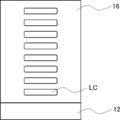
- FIG. 1 is a schematic view showing an example of an optical film.
- the optical film 10 has a resin base material 12 and an optically anisotropic layer 14 in this order. As shown in FIG. 1, the resin base material 12 and the optically anisotropic layer 14 are in direct contact with each other.
- each member constituting the optical film will be described in detail.
- the optical film has a resin base material.
- the resin base material has an orientation regulating force.
- the fact that the resin base material has an orientation regulating force means that the resin base material has a power to orient the liquid crystal compound when the liquid crystal compound is arranged on the surface of the resin base material. That is, the resin base material has an orientation regulating force for the liquid crystal compound.
- the resin base material having the orientation regulating force examples include a resin base material that has been subjected to a rubbing treatment and a resin base material that has been subjected to a stretching treatment, and a resin base material that has been subjected to a rubbing treatment is preferable. ..
- the direction of the rubbing treatment is not particularly limited, and the optimum direction is appropriately selected according to the direction in which the liquid crystal compound is desired to be oriented.
- a processing method widely adopted as a liquid crystal alignment processing step of an LCD (liquid crystal display) can be applied. That is, a method of obtaining orientation can be used by rubbing the surface of the resin base material in a certain direction with paper, gauze, felt, rubber, nylon fiber, polyester fiber, or the like.
- the transparent base material is intended to be a base material having a visible light transmittance of 60% or more, and the transmittance is preferably 80% or more, more preferably 90% or more.
- the resin constituting the resin base material a polymer having excellent optical performance transparency, mechanical strength, thermal stability, moisture shielding property, isotropic property and the like is preferable.
- the resin base material include a cellulose acylate film (for example, a cellulose triacetate film (refractive index 1.48), a cellulose diacetate film, a cellulose acetate butyrate film, a cellulose acetate propionate film), and a polyolefin film (for example, Polyethylene film and polypropylene film), polyester film (eg polyethylene terephthalate film and polyethylene naphthalate film), polyacrylic film (eg polymethylmethacrylate), polyethersulfone film, polyurethane film, polycarbonate film, polysulfone film, polyether film , Polymethylpentene film, polyether ketone film, (meth) acrylic nitrile film, and polymer film having an alicyclic structure (Norbornene resin (Arton: trade name, manufactured by JSR
- the adhesion between the resin base material and the optically anisotropic layer is more excellent, and the occurrence of optical defects in the optically anisotropic layer is further suppressed.
- Cellulose acylate, poly (meth) acrylate, polymer having an alicyclic structure, polystyrene, or in that the effect of at least one of the above can be obtained hereinafter, also simply referred to as "the point where the effect of the present invention is more excellent").
- Polycarbonate is preferred, and cellulose acylate is more preferred.
- the resin substrate contains various additives (for example, optical anisotropy adjuster, wavelength dispersion adjuster, fine particles, plasticizer, ultraviolet inhibitor, deterioration inhibitor, and release agent). May be good.
- additives for example, optical anisotropy adjuster, wavelength dispersion adjuster, fine particles, plasticizer, ultraviolet inhibitor, deterioration inhibitor, and release agent. May be good.
- the in-plane retardation of the resin base material at a wavelength of 550 nm is not particularly limited, but 10 nm or less is preferable in that the optical characteristics of the optically anisotropic layer can be more easily exhibited.
- the lower limit is not particularly limited, but 0 can be mentioned.
- SP (Solubility Parameter) value of the resin substrate is not particularly limited but is preferably 19.0 ⁇ 25.0 MPa 1/2, more preferably 20.0 ⁇ 23.0MPa 1/2.
- the SP value of the resin base material corresponds to the SP value of the resin constituting the resin base material.
- the sum is obtained by multiplying the squared value ( ⁇ d 2 , ⁇ p 2 , ⁇ h 2) of the three-dimensional SP value of each repeating unit by the body integration rate of each repeating unit.
- the squared value ( ⁇ d 2 , ⁇ p 2 , ⁇ h 2 ) of the three-dimensional SP value of the copolymer can be calculated and substituted into the above formula (X) to obtain the ⁇ a value of the copolymer.
- the thickness of the resin base material is not particularly limited, but is preferably 10 to 200 ⁇ m, more preferably 10 to 100 ⁇ m, and even more preferably 20 to 90 ⁇ m.
- the optically anisotropic layer contains a liquid crystal compound.
- the type of the liquid crystal compound is not particularly limited, and examples thereof include known liquid crystal compounds.
- the liquid crystal compound may be a low molecular weight compound or a high molecular weight compound.
- the low molecular weight compound means a compound having a molecular weight of 1000 or less
- the high molecular weight compound means a compound having a molecular weight of more than 1000.
- the liquid crystal compound contained in the optically anisotropic layer is preferably a polymer compound.
- the content of the liquid crystal compound in the optically anisotropic layer is not particularly limited, but is preferably 50% by mass or more, preferably 70% by mass or more, based on the total mass of the optically anisotropic layer in that the effect of the present invention is more excellent. Is more preferable.
- the upper limit is not particularly limited, but it is often 90% by mass or less.
- the optically anisotropic layer is preferably formed by using a composition containing a liquid crystal compound having a polymerizable group (hereinafter, also referred to as “polymerizable liquid crystal compound”). ..
- the liquid crystal compound contained in the optically anisotropic layer is preferably a polymer obtained by polymerizing a polymerizable liquid crystal compound.
- the type of the polymerizable liquid crystal compound is not particularly limited. In general, liquid crystal compounds can be classified into rod-shaped type (rod-shaped liquid crystal compound) and disk-shaped type (discotic liquid crystal compound) according to their shape. Further, the liquid crystal compound can be classified into a low molecular weight type and a high molecular weight type.
- a polymer generally refers to a polymer having a degree of polymerization of 100 or more (polymer physics / phase transition dynamics, by Masao Doi, p. 2, Iwanami Shoten, 1992).
- any liquid crystal compound can be used, but it is preferable to use a polymerizable rod-shaped liquid crystal compound or a polymerizable disk-shaped liquid crystal compound, and it is more preferable to use a polymerizable rod-shaped liquid crystal compound.
- Two or more kinds of polymerizable rod-shaped liquid crystal compounds, two or more kinds of polymerizable disk-shaped liquid crystal compounds, or a mixture of the polymerizable rod-shaped liquid crystal compound and the polymerizable disk-shaped liquid crystal compound may be used.
- polymerizable rod-shaped liquid crystal compound for example, those described in claim 1 of JP-A No. 11-513019 or paragraphs 0026 to 0098 of JP-A-2005-289980 can be preferably used.
- polymerizable disk-shaped liquid crystal compound for example, those described in paragraphs 0020 to 0067 of JP-A-2007-108732 or paragraphs 0013 to 0108 of JP-A-2010-2404038 can be preferably used.
- the type of the polymerizable group contained in the polymerizable liquid crystal compound is not particularly limited, and a functional group capable of an addition polymerization reaction is preferable, a polymerizable ethylenically unsaturated group or a ring-polymerizable group is more preferable, and an acryloyl group, a methacryloyl group, and the like.
- a vinyl group or a styryl group is more preferable.
- the optically anisotropic layer contains a compound having a hetero atom (specific compound), which is different from the liquid crystal compound described above. As will be described later, the specific compound is distributed at a predetermined position in the optical film.
- the specific compound has a heteroatom.
- the adhesion between the base material and the optically anisotropic layer is improved.
- the hetero atom an oxygen atom, a nitrogen atom, a sulfur atom, or a boron atom is preferable because the effect of the present invention is more excellent.
- the specific compound preferably has at least one selected from the group consisting of a urethane group, an ester group, an amide group, and a phenylboronic acid group in that the effect of the present invention is more excellent.
- the specific compound may be a low molecular weight compound or a high molecular weight compound.
- the low molecular weight compound means a compound having a molecular weight of 1000 or less
- the high molecular weight compound means a compound having a molecular weight of more than 1000.
- the specific compound contained in the optically anisotropic layer is preferably a polymer compound.
- the content of the specific compound in the optically anisotropic layer is not particularly limited, but is preferably 10% by mass or less, preferably 5% by mass or less, based on the total mass of the optically anisotropic layer in that the effect of the present invention is more excellent. Is more preferable, and 2% by mass or less is further preferable.
- the lower limit is not particularly limited, but is preferably 0.1% by mass or more, and more preferably 0.3% by mass or more.
- the optically anisotropic layer is preferably formed by using a composition containing a polymerizable compound having a heteroatom and a polymerizable group because the effect of the present invention is more excellent.
- the specific compound contained in the optically anisotropic layer is a polymer obtained by polymerizing a polymerizable compound having a heteroatom and a polymerizable group (hereinafter, also referred to as “specific polymerizable compound”). Is preferable.
- the specific polymerizable compound has a hetero atom.
- a hetero atom an oxygen atom, a nitrogen atom, a sulfur atom, or a boron atom is preferable because the effect of the present invention is more excellent.
- the specific polymerizable compound has at least one selected from the group consisting of a urethane group, an ester group, an amide group, and a phenylboronic acid group (-B (OH) 2) in that the effect of the present invention is more excellent. Is preferable.
- the specific polymerizable compound contains a repeating unit having a polymerizable group (hereinafter, also referred to as “unit 1”) and has a heteroatom in that the adhesion between the resin base material and the optically anisotropic layer is more excellent. It is preferably a polymer (hereinafter, also simply referred to as “specific polymerizable polymer”).
- the types of heteroatoms possessed by the specific polymerizable polymer are as described above.
- the specific polymerizable polymer preferably has at least one selected from the group consisting of a urethane group, an ester group, an amide group, and a phenylboronic acid group in that the effect of the present invention is more excellent. As will be described later, the specific polymerizable polymer may have a hetero atom in the unit 1.
- the type of the polymerizable group contained in the unit 1 is not particularly limited, a functional group capable of an addition polymerization reaction is preferable, a polymerizable ethylenically unsaturated group or a ring-polymerizable group is more preferable, and an acryloyl group, a methacryloyl group, and a vinyl group are preferable. , Or a styryl group is more preferred.
- the structure of the main chain of unit 1 is not particularly limited, and known structures can be mentioned, for example, (meth) acrylic skeleton, styrene skeleton, siloxane skeleton, cycloolefin skeleton, methylpentene skeleton, amide skeleton. , And a skeleton selected from the group consisting of aromatic ester-based skeletons is preferred. Of these, a skeleton selected from the group consisting of a (meth) acrylic skeleton, a siloxane skeleton, and a cycloolefin skeleton is more preferable, and a (meth) acrylic skeleton is even more preferable.
- the repeating unit represented by the formula (1) is preferable because the effect of the present invention is more excellent.
- R 1 represents a hydrogen atom or an alkyl group having 1 to 4 carbon atoms.
- L 1 represents a single bond or an n + 1 valent linking group.
- L 1 represents a divalent linking group
- L 1 represents a trivalent linking group.
- n represents 1.
- a divalent aliphatic hydrocarbon group for example, an alkylene group
- an arylene which may have a substituent
- Examples thereof include a group, a heteroarylene which may have a substituent, -O-, -CO-, -NH-, or a group in which two or more of these are combined.
- a divalent group which may have -CO-O-, -CO-NH-, -O-CO-NH-, and -CO-O- substituent may be used.
- Divalent aliphatic hydrocarbon group which may have an aliphatic hydrocarbon group-, -CO-NH- substituent-, a divalent aliphatic hydrocarbon which may have a -NH-substituted group.
- divalent aliphatic hydrocarbon group that may have a group-, -CO-O-substituted group-an arylene group that may have a substituent-, -CO-O-substituted group. May have divalent aliphatic hydrocarbon groups -O-, -CO-O- substituents may have divalent aliphatic hydrocarbon groups-NH-, -CO-O- substituents. Divalent aliphatic hydrocarbon group -O-CO-NH- which may have a divalent aliphatic hydrocarbon group which may have an -CO-O- substituent-O-CO- Examples thereof include a divalent aliphatic hydrocarbon group-O-which may have an NH-substituted group.
- the trivalent linking group examples include a trivalent aliphatic hydrocarbon group which may have a substituent, a trivalent aromatic group which may have a substituent, a nitrogen atom (> N-), and the like. Examples thereof include a group in which these groups and the above-mentioned divalent linking group are combined.
- L 1 preferably n + 1 valent linking group containing a hetero atom, more preferably a trivalent linking group containing a divalent linking group or a hetero atom containing a hetero atom, a urethane group, an ester group, and ,
- a divalent linking group containing at least one selected from the group consisting of amide groups is more preferred.
- the divalent linking group containing at least one selected from the group consisting of a urethane group, an ester group and an amide group includes at least one selected from the group consisting of a urethane group, an ester group and an amide group.
- a group in combination with an aliphatic hydrocarbon group is preferable, and examples thereof include a group exemplified in "a group in which two or more of these are combined" described in the above-mentioned divalent linking group.
- P 1 represents a polymerizable group.
- the definition of the polymerizable group is as described above.
- N represents an integer of 1 or more. Among them, 1 or 2 is preferable as n, and 1 is more preferable, from the viewpoint that the effect of the present invention is more excellent.
- the content of unit 1 in the specific polymerizable polymer is not particularly limited, but is preferably 20% by mass or more, preferably 50% by mass, based on all the repeating units of the specific polymerizable polymer in that the effect of the present invention is more excellent. % Or more is more preferable, and 70% by mass or more is further preferable.
- the upper limit is not particularly limited, but 100% by mass is mentioned, and in many cases, it is 95% by mass or less.
- Examples of the unit 1 include the repeating unit shown in Table 1 below.
- the specific polymerizable polymer may contain a repeating unit other than the unit 1 (hereinafter, also referred to as “unit 2”).
- the unit 2 is not particularly limited, but a repeating unit represented by the formula (2) can be mentioned because the effect of the present invention is more excellent.
- R 2 represents a hydrogen atom or an alkyl group having 1 to 4 carbon atoms.
- L 2 represents a single bond or a divalent linking group.
- Examples of the divalent linking group include the groups exemplified as the divalent linking group represented by L 1 described above.
- R 3 represents a hydrocarbon group which may have a substituent. Among them, an aliphatic hydrocarbon group or an aromatic hydrocarbon group (preferably a benzene ring), which may have a substituent, is preferable because the effect of the present invention is more excellent.
- the number of carbon atoms contained in the aliphatic hydrocarbon group is not particularly limited, but 1 to 20 is preferable, and 1 to 10 is more preferable.
- the aliphatic hydrocarbon group may be linear or branched.
- the aliphatic hydrocarbon group may have a cyclic structure.
- the substituent is not particularly limited, but for example, an alkyl group, an alkoxy group, an alkyl substituted alkoxy group, a cyclic alkyl group, an aryl group (for example, a phenyl group and a naphthyl group), a cyano group, an amino group, a nitro group, and an alkylcarbonyl.
- Examples include groups, sulfo groups, and hydroxyl groups.
- the content of unit 2 (for example, the repeating unit represented by the above formula (2)) is not particularly limited, but the specific polymerizable polymer can be used as all repeating units.
- 80% by mass or less is preferable, 50% by mass or less is more preferable, and 30% by mass or less is further preferable.
- the lower limit is not particularly limited, but may be 10% by mass or more.
- the weight average molecular weight of the specific polymerizable polymer is not particularly limited, but is preferably 5000 or more because the effect of the present invention is more excellent.
- the upper limit is not particularly limited, but 50,000 or less is preferable because the effect of the present invention is more excellent.
- the weight average molecular weight and the number average molecular weight in the present invention are values measured by a gel permeation chromatography (GPC) method under the conditions shown below.
- Equation (3) R 4- L 3- R 5 R 4 represents a polymerizable group.
- the definition of the polymerizable group is as described above.
- L 3 represents a single bond or a divalent linking group. Examples of the divalent linking group include the groups exemplified as the divalent linking group represented by L 1 described above.
- R 5 represents a boronic acid group or a hydroxy group.
- the absolute value of the difference between the SP value of the specific polymerizable compound and the SP value of the resin base material described above is not particularly limited, but 2.7 MPa 1/2 or less is preferable in that the effect of the present invention is more excellent. It is more preferably 0 MPa 1/2 or less.
- the lower limit is not particularly limited, but 0 can be mentioned.
- the optically anisotropic layer may contain components other than the liquid crystal compound and the specific compound described above. Examples of other components include other components (for example, chiral agents) that can be contained in the composition used for forming the optically anisotropic layer described later. Further, as will be described later, the optically anisotropic layer may contain a resin constituting a resin base material. In particular, the resin constituting the resin base material may be contained in the vicinity of the surface of the optically anisotropic layer on the resin base material side.
- the surface of the optical film on the optically anisotropic layer side is the first surface
- the surface of the optical film on the resin substrate side is the second surface
- the optical film of the present invention satisfies both the following requirements 1 and 2.
- Requirement 1 Derived from the resin constituting the resin base material, the depth position located on the second surface side showing the secondary ionic strength, which is 80% of the maximum strength of the secondary ionic strength derived from the liquid crystal compound, is set as the A position.
- the depth position located on the most first surface side showing the secondary ionic strength which is 80% of the maximum strength of the secondary ionic strength
- the maximum value Imax of the secondary ionic strength derived from the compound having a hetero atom is shown.
- Requirement 2 The peak position is the depth position showing the maximum value Imax of the secondary ionic strength derived from the compound having a hetero atom, and the peak position is on the first surface side of the peak position showing the secondary ionic strength of the maximum value Imax.
- the depth position closest to the peak position was defined as the C position, and the depth position closest to the peak position on the second surface side of the peak position, which shows the secondary ionic strength that is half of the maximum value Imax, was defined as the D position.
- the distance between the C position and the D position is 100 nm or less.
- FIG. 2 is an example of a profile obtained by analyzing the components in the depth direction in each layer by TOF-SIMS while ion-sputtering from the first surface 10A to the second surface 10B of the optically anisotropic layer of FIG. Shown.
- the depth direction is intended to be a direction toward the second surface with reference to the first surface of the optically anisotropic layer.
- the surface of the optical film 10 on the optically anisotropic layer 14 side is referred to as the first surface 10A
- the surface of the optical film 10 on the resin base material 12 side is referred to as the second surface 10B.
- the horizontal axis in FIG. 2, the axis extending in the left-right direction of the paper surface
- the vertical axis in FIG. 2.
- the axis extending in the vertical direction of the paper surface represents the secondary ionic strength of each component.
- the components in the depth direction of the optical film by TOF-SIMS while irradiating the ion beam after performing the component analysis in the surface depth region of 1 to 2 nm, the components are further analyzed in the depth direction from 1 nm to several hundreds. The series of operations of digging in nm and performing component analysis in the next surface depth region of 1 to 2 nm is repeated.
- the "secondary ionic strength derived from the liquid crystal compound" determined by the profile in the depth direction detected by analyzing the components in the depth direction of the optical film by TOF-SIMS is defined as the liquid crystal compound.
- the "secondary ionic strength derived from the resin” is intended to be the strength of the fragment ion derived from the resin constituting the resin base material, and is intended to be the “secondary ionic strength derived from a specific compound”. Means the intensity of fragment ions derived from a particular compound.
- the TOF-SIMS method is performed while irradiating an ion beam from the first surface 10A side to the second surface 10B side of the optical film 10 (toward the direction of the white arrow in FIG. 1).
- the secondary ion intensity derived from the liquid crystal compound in the optically anisotropic layer 14 is observed to be high, and when the ion beam is further irradiated in the depth direction, the liquid crystal is liquid crystal.
- the secondary ion intensity derived from the compound gradually decreases. This means that the optically anisotropic layer 14 is approaching the resin base material 12.
- the resin base material 12 is reached and the secondary ionic strength derived from the liquid crystal compound is not observed.
- the secondary ionic strength derived from the resin constituting the resin base material 12 is on the second surface 10B side. It increases as it goes toward.
- the resin base material 12 is reached, and the secondary ionic strength derived from the resin constituting the resin base material 12 becomes the highest.
- FIG. 2 the result of the secondary ionic strength derived from the specific compound (C3 in the figure) is shown.
- the secondary ion derived from the specific compound is strongly observed. More specifically, first, in the profile in the depth direction shown in FIG. 2, the depth located on the second surface side showing the secondary ionic strength which is 80% of the maximum strength of the secondary ionic strength derived from the liquid crystal compound.
- the position A is the position A, and the depth position located on the most first surface side showing the secondary ionic strength, which is 80% of the maximum strength of the secondary ionic strength derived from the resin constituting the resin base material, is the position B. ..
- the maximum intensity of the secondary ionic strength derived from the liquid crystal compound corresponds to M1
- the position close to the surface) is defined as the A position. Therefore, for example, when there are a plurality of depth positions showing 80% of the secondary ionic strength of M1, the depth position located closest to the second surface side is set as the A position. Further, in FIG.
- the closest position) is the B position. Therefore, for example, when there are a plurality of depth positions showing 80% of the secondary ionic strength of M2, the depth position located closest to the first surface side is set as the B position.
- a region between 50 nm from the first surface toward the second surface side hereinafter, also referred to as the first surface region.
- the secondary ionic strength of each component in the region between the second surface and the first surface side of 50 nm is the calculation of the maximum intensity described above. Do not take this into consideration. More specifically, the maximum intensity of the secondary ionic strength derived from the liquid crystal compound is defined in the region excluding the first surface region and the second surface region in the profile of the secondary ionic strength derived from the obtained liquid crystal compound. The maximum intensity of the secondary ionic strength derived from the liquid crystal compound is calculated as the maximum intensity.
- the maximum strength of the secondary ionic strength derived from the resin is the secondary ionic strength derived from the resin in the region excluding the first surface region and the second surface region in the profile of the secondary ionic strength derived from the obtained resin.
- the maximum strength of the strengths is calculated as the maximum strength.
- the maximum value Imax of the secondary ionic strength derived from the specific compound is shown at any depth position between the A position and the B position specified above.
- the maximum value Imax is shown at the peak position PP. That is, the maximum value Imax of the secondary ionic strength derived from the specific compound is observed between the A position and the B position.
- the specific compound is unevenly distributed on the resin substrate side in the tree optically anisotropic layer. By satisfying such requirement 1, the adhesion between the resin base material and the optically anisotropic layer becomes good.
- a peak showing the maximum value Imax is observed at the peak position PP located between the A position and the B position.
- the C position is a depth position located on the first surface side of the peak position and closest to the peak position, which shows a secondary ionic strength (Imax / 2) that is half of the maximum value Imax.
- the white arrow indicates the secondary ionic strength (Imax / 2), which is half of the maximum value Imax, when the depth position closest to the peak position on the second surface side of the peak position is the D position.
- the distance between the C position and the D position (hereinafter, also referred to as Iwid) is 100 nm or less. In the optical film satisfying the requirement 2, the amount of the specific compound unevenly distributed is not more than a predetermined amount.
- the Iwid becomes more than 100 nm.
- the orientation of the liquid crystal compound in the optically anisotropic layer is improved, and the occurrence of optical defects in the optically anisotropic layer is suppressed.
- the requirement 2 is not satisfied, the amount of the specific compound is too large, so that the orientation regulating force of the resin base material is weakened, and the orientation of the liquid crystal compound is deteriorated.
- the Iwid is preferably 50 nm or less in that the occurrence of optical defects in the optically anisotropic layer is further suppressed.
- the lower limit is not particularly limited, but it is often 1 nm or more, and more often 5 nm or more.
- the effect of the present invention is more excellent, when the average intensity of the secondary ionic strength derived from the specific compound from the first surface to the A position is set to the average value Iave, the maximum value Imax and the average value Iave are set. It is preferable to satisfy the relationship of the formula (A).
- Formula (A) 1.3 ⁇ Imax / Iave Among them, Imax / Iave is preferably 50 or more, more preferably 100 or more, in that the effect of the present invention is more excellent.
- the upper limit is not particularly limited, but Imax / Iave is often 1000 or less, and more often 500 or less.
- Ionic strength is not taken into account when calculating Iave as described above. More specifically, Iave is a 2 derived from a specific compound in the obtained profile of the secondary ionic strength derived from the specific compound in the region from the first surface to the A position excluding the first surface region. The average intensity of the next ionic strength.
- the method for producing the optical film of the present invention is not particularly limited, but a composition containing a polymerizable liquid crystal compound and a specific polymerizable compound (hereinafter, also simply referred to as “specific composition”” is obtained in that an optical film can be produced with high productivity.
- the method using) is preferable. More specifically, a specific composition is applied onto a resin base material having an orientation-regulating force to form a composition layer, the polymerizable liquid crystal compound in the composition layer is oriented, and then the polymerizable liquid crystal compound is formed.
- a method of producing an optical film having a resin base material and an optically anisotropic layer formed on the resin base material is preferable by immobilizing the orientation state of the above.
- the procedure of the above method will be described in detail.
- the resin base material having an orientation regulating force used in the above manufacturing method is as described above.
- the polymerizable liquid crystal compound and the specific polymerizable compound (preferably the specific polymerizable polymer) contained in the specific composition are as described above.
- the content of the polymerizable liquid crystal compound in the specific composition is not particularly limited, but is preferably 50% by mass or more, more preferably 70% by mass or more, based on the total solid content in the specific composition.
- the upper limit is not particularly limited, but it is often 90% by mass or less.
- the content of the specific polymerizable compound in the specific composition is preferably 10% by mass or less, more preferably 5% by mass or less, still more preferably 2% by mass or less, based on the total mass of the polymerizable liquid crystal compound.
- the lower limit is not particularly limited, but is preferably 0.1% by mass or more, and more preferably 0.3% by mass or more.
- the solid content means a component capable of forming an optically anisotropic layer from which the solvent in the specific composition has been removed, and is a solid content even if the property is liquid.
- the specific composition may contain components other than the above-mentioned polymerizable liquid crystal compound and the specific polymerizable compound.
- the specific composition may contain a solvent.
- the solvent include ester-based solvents, ether-based solvents, amide-based solvents, carbonate-based solvents, ketone-based solvents, aliphatic hydrocarbon-based solvents, alicyclic hydrocarbon-based solvents, aromatic hydrocarbon-based solvents, and halogenation.
- Examples include carbon-based solvents, water, and alcohol-based solvents. Of these, an ester solvent, an ether solvent, an amide solvent, a carbonate solvent, or a ketone solvent is preferable. Further, only one type of solvent may be used, or two or more types may be mixed and used.
- the specific composition may contain a polymerization initiator.
- the polymerization initiator include known polymerization initiators, photopolymerization initiators and thermal polymerization initiators, and photopolymerization initiators are preferable.
- the content of the polymerization initiator in the specific composition is not particularly limited, but is preferably 0.01 to 20% by mass, more preferably 0.5 to 10% by mass, based on the total solid content in the specific composition.
- the specific composition may contain a surfactant.
- the surfactant include conventionally known compounds, but fluorine-based compounds are preferable. Specifically, for example, the compounds described in paragraphs 0028 to 0056 of JP-A-2001-330725 and the compounds described in paragraphs 0069 to 0126 of JP-A-2005-062673 can be mentioned.
- the specific composition may include a polymer.
- the polymer include cellulose esters.
- examples of the cellulose ester include those described in paragraph 0178 in JP-A-2000-155216.
- the content of the polymer in the specific composition is not particularly limited, but is preferably 0.1 to 10% by mass, more preferably 0.1 to 8% by mass, based on the total mass of the polymerizable liquid crystal compound.
- the specific composition may contain an additive (orientation control agent) that promotes horizontal orientation or vertical orientation in order to bring the polymerizable liquid crystal compound into a horizontal or vertical orientation state.
- an additive orientation control agent
- the specific composition may further contain a chiral agent.
- the polymerizable liquid crystal compound can be twist-oriented along the spiral axis.
- the type of chiral auxiliary is not particularly limited. Use any of the known chiral agents (for example, "Liquid Crystal Device Handbook” edited by the 142nd Committee of the Japan Society for the Promotion of Science, Chapter 3, 4-3, TN, Chiral Auxiliary for STN, p. 199, 1989). Can be done.
- the spiral-inducing force (HTP) of the chiral agent is a factor indicating the spiral orientation ability represented by the following formula (X).
- Formula (X) HTP 1 / (length of spiral pitch (unit: ⁇ m) ⁇ concentration of chiral auxiliary to liquid crystal compound (mass%)) [ ⁇ m -1 ]
- the chiral agent may be a photosensitive chiral agent whose spiral-inducing force changes with light irradiation (hereinafter, also simply referred to as “chiral agent A”).
- the chiral agent A may be liquid crystal or non-liquid crystal.
- the chiral agent A generally contains an asymmetric carbon atom in many cases.
- the chiral agent A may be an axial asymmetric compound or a planar asymmetric compound that does not contain an asymmetric carbon atom.
- the chiral agent A may have a polymerizable group.
- the chiral agent A may be a chiral agent whose spiral-inducing force is increased or decreased by light irradiation. Of these, a chiral agent whose spiral inducing force is reduced by light irradiation is preferable.
- “increase and decrease of spiral-inducing force” means increase / decrease when the initial spiral direction (before light irradiation) of chiral agent A is "positive". Therefore, when the spiral inducing force continues to decrease due to light irradiation and the spiral direction becomes "negative" beyond 0 (that is, a spiral in the spiral direction opposite to the initial (before light irradiation) spiral direction is induced). (Case) also falls under the category of "chiral agent with reduced spiral inducing force".
- Examples of the chiral agent A include so-called photoreactive chiral agents.
- the photoreactive chiral agent is a compound having a chiral portion and a photoreactive portion whose structure is changed by light irradiation, and for example, the twisting force of the liquid crystal compound is significantly changed according to the irradiation amount.
- a compound having at least a photoisomerization site is preferable, and the photoisomerization site is more preferably having a photoisomerizable double bond.
- the photoisomerization site having a photoisomerizable double bond is a cinnamoyl site, a chalcone site, an azobenzene site or a azobenzene site in that photoisomerization is likely to occur and the difference in spiral-induced force before and after light irradiation is large.
- the stilbene moiety is preferred, and the cinnamoyl moiety, chalcone moiety or stilbene moiety is more preferred in that it absorbs less visible light.
- the photoisomerization site corresponds to the photoreaction site whose structure is changed by the above-mentioned light irradiation.
- the chiral agent A has one of a partial structure selected from a binaphthyl partial structure, an isosorbide partial structure (a partial structure derived from isosorbide), and an isomannide partial structure (a partial structure derived from isosorbide). Is preferable.
- the binaphthyl partial structure, the isosorbide partial structure, and the isosorbide partial structure are intended to have the following structures, respectively.
- the part of the binaphthyl substructure where the solid line and the broken line are parallel represents a single bond or a double bond. In the structure shown below, * represents the bonding position.
- the specific composition may contain two or more kinds of chiral auxiliary A, or a chiral agent whose spiral inducing force does not change by irradiation with at least one kind of chiral agent A and at least one kind of light (hereinafter, simply "chiral agent B"). It may also include.).
- the chiral agent B may be liquid crystal or non-liquid crystal.
- the chiral agent B generally contains an asymmetric carbon atom in many cases.
- the chiral agent B may be an axial asymmetric compound or a planar asymmetric compound that does not contain an asymmetric carbon atom.
- the chiral agent B may have a polymerizable group.
- As the chiral agent B a known chiral agent can be used.
- the chiral agent B is preferably a chiral agent that induces a spiral in the opposite direction to the above-mentioned chiral agent A. That is, for example, when the spiral induced by the chiral agent A is in the right direction, the spiral induced by the chiral agent B is in the left direction.
- the absolute value of the weighted average helical twisting power of the chiral agent is preferably 0.0 ⁇ 1.9 .mu.m -1, more preferably 0.0 ⁇ 1.5 ⁇ m -1, 0.0 ⁇ 1 . It is more preferably 0 ⁇ m -1 , particularly preferably 0.0 to 0.5 ⁇ m -1 , and most preferably zero.
- the absolute value of the weighted average spiral inducing force of the chiral auxiliary is in the above range, as will be described later, two or more layers having different optical characteristics along the thickness direction depending on the manufacturing conditions of the optically anisotropic layer. It is easy to form an optically anisotropic layer having.
- the weighted average spiral inducing force of the chiral auxiliary is the spiral inducing force of each chiral auxiliary and the concentration (mass) of each chiral agent with respect to the polymerizable liquid crystal compound when two or more kinds of chiral agents are contained in the specific composition. %) Divided by the total concentration (% by mass) of the chiral auxiliary with respect to the polymerizable liquid crystal compound.
- Y the following formula
- the spiral-inducing force is a negative value. That is, for example, if helical twisting power of the chiral agent of 10 [mu] m -1, when the spiral direction of the spiral, which is induced by the chiral agent is a right-handed represents a helical twisting power as 10 [mu] m -1. On the other hand, when the spiral direction of the spiral induced by the chiral agent is left-handed, the spiral-inducing force is expressed as -10 ⁇ m -1.
- the content of the chiral agent A in the specific composition is not particularly limited, but is preferably 5.0% by mass or less with respect to the total mass of the polymerizable liquid crystal compound in that the polymerizable liquid crystal compound is easily oriented uniformly. , 3.0% by mass or less is more preferable, and 2.0% by mass or less is further preferable.
- the lower limit is not particularly limited, but is preferably 0.01% by mass or more, and more preferably 0.02% by mass or more.
- the chiral auxiliary A may be used alone or in combination of two or more. When two or more of the above chiral agents A are used in combination, the total content is preferably within the above range.
- the content of the chiral agent B in the specific composition is not particularly limited, but is preferably 5.0% by mass or less with respect to the total mass of the polymerizable liquid crystal compound in that the polymerizable liquid crystal compound is easily oriented uniformly. , 3.0% by mass or less is more preferable, and 2.0% by mass or less is further preferable.
- the lower limit is not particularly limited, but is preferably 0.01% by mass or more, and more preferably 0.02% by mass or more.
- the chiral agent B may be used alone or in combination of two or more. When two or more of the above chiral agents B are used in combination, the total content is preferably within the above range.
- the total content of the chiral auxiliary (total content of all chiral agents) in the specific composition is preferably 5.0% by mass or less, preferably 4.0% by mass or less, based on the total mass of the polymerizable liquid crystal compound. More preferably, 2.0% by mass or less is even more preferable.
- the lower limit is not particularly limited, but is preferably 0.01% by mass or more, and more preferably 0.02% by mass or more.
- a specific composition is applied onto a resin base material to form a composition layer.
- the specific composition is applied directly onto the resin substrate.
- the specific composition is applied so that the surface of the resin base material is in contact with the specific composition.
- the coating method is not particularly limited, and examples thereof include a wire bar coating method, an extrusion coating method, a direct gravure coating method, a reverse gravure coating method, and a die coating method. If necessary, after the application of the specific composition, a treatment of drying the composition layer applied on the resin base material may be carried out. By carrying out a drying treatment, the solvent can be removed from the composition layer.
- the film thickness of the composition layer is not particularly limited, but is preferably 0.1 to 20 ⁇ m, more preferably 0.2 to 15 ⁇ m, and even more preferably 0.5 to 10 ⁇ m.
- the polymerizable liquid crystal compound in the composition layer is oriented.
- the treatment for orienting the polymerizable liquid crystal compound is not particularly limited, but heat treatment is preferable.
- the heat treatment conditions the optimum conditions are selected according to the polymerizable liquid crystal compound used.
- the heating temperature is often 10 to 250 ° C, more often 40 to 150 ° C, and even more often 50 to 130 ° C.
- the heating time is often 0.1 to 60 minutes, and more often 0.2 to 5 minutes.
- the orientation of the polymerizable liquid crystal compound depends on the material in the composition layer. Examples of the orientation state include homogenius orientation. When the composition layer contains a chiral agent, the polymerizable liquid crystal compound is twist-oriented along a spiral axis extending along the thickness direction of the composition layer.
- the orientation state of the polymerizable liquid crystal compound is fixed to form an optically anisotropic layer.
- the method for immobilizing the orientation state is not particularly limited, and the composition layer is subjected to a curing treatment to react the polymerizable groups in the polymerizable liquid crystal compound to form an optically anisotropic layer (cured layer). There is a way to do it.
- the method of curing treatment is not particularly limited, and examples thereof include photo-curing treatment and thermosetting treatment. Among them, the light irradiation treatment is preferable, and the ultraviolet irradiation treatment is more preferable.
- a light source such as an ultraviolet lamp is used for ultraviolet irradiation.
- the irradiation amount of light (for example, ultraviolet rays) is not particularly limited, but is generally preferably about 100 to 800 mJ / cm 2.
- the orientation state of the polymerizable liquid crystal compound is fixed.
- examples of the optically anisotropic layer include a layer formed by immobilizing a homogeneously oriented polymerizable liquid crystal compound.
- a layer formed by immobilizing a polymerizable liquid crystal compound twist-oriented having a spiral axis in the thickness direction can be mentioned.
- the "fixed” state means a state in which the orientation of the liquid crystal compound is maintained. It is not limited to that, and specifically, in the temperature range of 0 to 50 ° C., and more severely, -30 to 70 ° C., the layer has no fluidity, and is oriented by an external field or an external force. It is preferable that the fixed orientation form can be kept stable without causing a change. In the optically anisotropic layer, it is no longer necessary for the composition in the layer to finally exhibit liquid crystallinity.
- the optically anisotropic layer may have a single-layer structure or a multi-layer structure.
- the multi-layer structure means a structure in which two or more layers having different optical characteristics are laminated.
- steps A to E can be carried out to produce an optically anisotropic layer having two layers having different optical characteristics in one coating step. it can.
- Step A A specific composition containing a chiral agent A is applied onto a resin substrate to form a composition layer.
- Step B A heat treatment is applied to the composition layer to obtain a polymerizable liquid crystal compound in the composition layer.
- Step C After step B, the composition layer is irradiated with light under the condition of an oxygen concentration of 1% by volume or more.
- Step D After step C, the composition layer is heat-treated.
- step E After step D, the composition layer is cured to fix the orientation of the polymerizable liquid crystal compound and form an optically anisotropic layer. It will be described in detail.
- Step A Examples of the procedure of the step A include the above-mentioned procedure of applying the specific composition.
- the specific composition used in step A contains a chiral agent A in addition to the above-mentioned polymerizable liquid crystal compound and specific polymerizable compound.
- the specific composition may contain a chiral agent B.
- Step B The procedure of step B is not particularly limited, and examples thereof include a method of orienting the above-mentioned polymerizable liquid crystal compound.
- Step C Step C will be described below with reference to the drawings.
- the specific composition contains two types of chiral agents, chiral agent A and chiral agent B, and the absolute value of the weighted average spiral inducing force of the chiral agent in the composition layer formed by step A is 0. The case where is is typically described.
- the composition layer 16 in which the polymerizable liquid crystal compound LC is homogenically oriented is formed on the resin base material 12 by the step B.
- FIG. 3 is a schematic cross-sectional view of the resin base material 12 and the composition layer 16.
- step C the direction opposite to the composition layer 16 side of the resin base material 12 under the condition of an oxygen concentration of 1% by volume or more (the direction of the white arrow in FIG. 4). Light irradiation is performed from.
- the chiral agent A is also present in the lower region 16A, and the chiral agent A is also exposed to light, and the spiral inducing force changes.
- the orientation state of the polymerizable liquid crystal compound is fixed in the lower region 16A, the orientation of the liquid crystal compound is even if the step D of heat-treating the light-irradiated composition layer, which will be described later, is performed. There is no change in state.
- the oxygen concentration is high in the upper region 16B, even if light irradiation is performed, the polymerization of the polymerizable liquid crystal compound is inhibited by oxygen, and the polymerization is difficult to proceed.
- step D heat treatment
- step C the orientation state of the polymerizable liquid crystal compound is likely to be fixed in the region (lower region) of the composition layer on the resin substrate side. Further, in the region of the composition layer opposite to the resin base material side (upper region), the solidification of the oriented state of the polymerizable liquid crystal compound is difficult to proceed, and the spiral inducing force changes depending on the exposed chiral agent A. It will be in the state of.
- Step C is carried out under the condition that the oxygen concentration is 1% by volume or more.
- the oxygen concentration is preferably 2% by volume or more, more preferably 5% by volume or more, in that layers having different orientation states of the polymerizable liquid crystal compound are easily formed in the optically anisotropic layer.
- the upper limit is not particularly limited, but 100% by volume can be mentioned.
- the irradiation intensity of light irradiation in step C is not particularly limited and can be appropriately determined based on the spiral inducing force of the chiral agent A.
- the irradiation amount of light irradiation in the step C is not particularly limited, but is preferably 300 mJ / cm 2 or less, more preferably 200 mJ / cm 2 or less, in that a predetermined optically anisotropic layer is easily formed.
- the lower limit, in terms of easy predetermined optical anisotropic layer is formed is preferably 10 mJ / cm 2 or more, 30 mJ / cm 2 or more is more preferable.
- the light irradiation in step C is preferably carried out at 15 to 70 ° C. (preferably 15 to 50 ° C.).
- the light used for light irradiation may be the light that the chiral agent A is exposed to. That is, the light used for light irradiation is not particularly limited as long as it is an active ray or radiation that changes the spiral inducing force of the chiral agent A.
- the emission line spectrum of a mercury lamp far ultraviolet rays typified by an excimer laser, and poles. Examples include ultraviolet rays, X-rays, ultraviolet rays, and electron beams. Of these, ultraviolet rays are preferable.
- Step D is a step of heat-treating the composition layer after step C.
- the orientation state of the liquid crystal compound changes in the region where the spiral inducing force of the chiral auxiliary A in the composition layer subjected to light irradiation has changed.
- the orientation state of the polymerizable liquid crystal compound is fixed in the lower region 16A as shown in FIG.
- the polymerization of the polymerizable liquid crystal compound is difficult to proceed, and the orientation state of the polymerizable liquid crystal compound is not fixed.
- the spiral inducing force of the chiral agent A changes.
- the force for twisting the polymerizable liquid crystal compound changes in the upper region 16B as compared with the state before light irradiation. This point will be described in more detail.
- the chiral agent A and the chiral agent B are present in the composition layer 16 shown in FIG. 3 at the same concentration, the spiral direction induced by the chiral agent A is left-handed, and the chiral agent B causes the composition layer 16.
- the induced spiral direction is right-handed.
- the absolute value of the spiral-inducing force of the chiral agent A and the absolute value of the spiral-inducing force of the chiral agent B are the same. Therefore, the weighted average spiral inducing force of the chiral agent in the composition layer before light irradiation is 0.
- the vertical axis represents “the spiral inducing force of the chiral agent ( ⁇ m- 1 ) ⁇ the concentration of the chiral agent (mass%)”, and the farther the value is from zero, the greater the spiral inducing force.
- the horizontal axis represents "light irradiation amount (mJ / cm 2 )”.
- the relationship between the chiral agent A and the chiral agent B in the composition layer before light irradiation corresponds to the time when the light irradiation amount is 0, and "the spiral inducing force of the chiral auxiliary A ( ⁇ m- 1 ) ⁇ "
- the absolute value of "concentration of chiral auxiliary A (mass%)” and “spiral-inducing force of chiral agent B ( ⁇ m- 1 ) x concentration of chiral agent B (% by mass)” correspond to the same state. That is, the spiral-inducing forces of both the chiral agent A that induces left-handed winding and the chiral agent B that induces right-handed winding cancel each other out.
- the composition layer 16 after the step C in which such a change in the weighted average spiral inducing force is generated is heat-treated to promote the reorientation of the liquid crystal compound, as shown in FIG. 4, the upper side is shown.
- the polymerizable liquid crystal compound LC is twist-oriented along a spiral axis extending along the thickness direction of the composition layer 16.
- the polymerization of the polymerizable liquid crystal compound proceeds during step C and the orientation state of the polymerizable liquid crystal compound is fixed, so that the polymerizable liquid crystal compound is polymerizable. The reorientation of the liquid crystal compound does not proceed.
- step D by carrying out the step D, a plurality of regions having different orientation states of the polymerizable liquid crystal compound are formed along the thickness direction of the composition layer.
- the degree of twisting of the polymerizable liquid crystal compound LC can be appropriately adjusted depending on the type of chiral agent A used, the exposure amount in step C, and the like.
- the present invention is not limited to this embodiment.
- a chiral agent whose spiral inducing force is increased by light irradiation may be used as the chiral agent A.
- the spiral inducing force induced by the chiral agent A increases due to light irradiation, and the liquid crystal compound is twisted or oriented in the turning direction induced by the chiral auxiliary A.
- the mode in which the chiral agent A and the chiral agent B are used in combination has been described, but the mode is not limited to this mode.
- it may be an embodiment using two kinds of chiral agents A.
- the chiral agent A1 that induces left-handed winding and the chiral agent A2 that induces right-handed winding may be used in combination.
- the chiral agents A1 and A2 may be chiral agents whose spiral inducing force increases or chiral agents whose spiral inducing force decreases, respectively.
- a chiral agent that induces left-handed winding and whose spiral-inducing force increases by light irradiation and a chiral agent that induces right-handed winding and whose spiral-inducing force decreases by light irradiation are used in combination. You may.
- the optimum conditions are selected according to the liquid crystal compound used.
- the heating temperature is preferably a temperature for heating from the state of step C, often 35 to 250 ° C, more often 50 to 150 ° C, and more than 50 ° C and 150 ° C or less. Even more, especially at 60-130 ° C.
- the heating time is often 0.01 to 60 minutes, and more often 0.03 to 5 minutes.
- the absolute value of the weighted average spiral inducing force of the chiral agent in the composition layer after light irradiation is not particularly limited, but the weighted average spiral inducing force of the chiral agent in the composition layer after light irradiation and before light irradiation.
- the absolute value of the difference between the weighted average helical twisting power preferably 0.05 .mu.m -1 or more, more preferably 0.05 ⁇ 10.0 [mu] m -1, more preferably 0.1 ⁇ 10.0 [mu] m -1.
- the procedure of step E is not particularly limited, and examples thereof include the above-mentioned curing treatment.
- the optically anisotropic layer formed is a layer formed by fixing the orientation state of the homogeneously oriented polymerizable liquid crystal compound from the resin base material side. It includes two layers, one is a layer obtained by fixing the orientation state of the polymerizable liquid crystal compound twisted and oriented along a spiral axis extending along the thickness direction. That is, the formed optically anisotropic layer has a multi-layer structure.
- optical film can be applied to various uses, and examples thereof include an optical compensation film for optically compensating a liquid crystal cell and an antireflection film used in a display device such as an organic electroluminescence display device.
- the above-mentioned optical film may be used as a circular polarizing plate in combination with a polarizer.
- the polarizer may be a member having a function of converting natural light into specific linearly polarized light, and examples thereof include an absorption type polarizer.
- the type of the polarizer is not particularly limited, and a commonly used polarizer can be used, and examples thereof include an iodine-based polarizer, a dye-based polarizer using a dichroic dye, and a polyene-based polarizer.
- Iodine-based polarizers and dye-based polarizers are generally produced by adsorbing iodine or a dichroic dye on polyvinyl alcohol and stretching it.
- a protective film may be arranged on one side or both sides of the polarizer.
- the method for producing the circular polarizing plate is not particularly limited, and a known method can be adopted. For example, a method of adhering an optical film and a polarizer via an adhesive layer can be mentioned.
- the circularly polarizing plate can be suitably applied as an antireflection film for an organic EL display device.
- Example 1> Preparation of Cellulose Achillate Film (Substrate)
- the following components are put into a mixing tank, stirred, heated at 90 ° C. for 10 minutes, filtered through a filter paper having an average pore size of 34 ⁇ m and a sintered metal filter having an average pore size of 10 ⁇ m, and subjected to cellulose acylate dope (hereinafter, simply “” Also called “dope”) was manufactured.
- Cellulose acylate dope ⁇ Cellulose acylate (acetyl substitution degree 2.86, viscosity average degree of polymerization 310) 100 parts by mass sugar ester compound 1 (shown in chemical formula (S4)) 6.0 parts by mass sugar ester compound 2 (shown in chemical formula (S5)) 2.0 parts by mass silica particle dispersion (AEROSIL R972, Nippon Aerosil Co., Ltd.) Made) 0.1 parts by mass Solvent (methylene chloride / methanol / butanol) Predetermined amount ⁇
- the above-mentioned doping was cast using a drum film forming machine.
- the above-mentioned doping for forming the core layer so as to be in contact with the metal substrate cooled to 0 ° C. and the above-mentioned doping for forming the surface layer on the core layer were co-cast from the die, and then obtained.
- the film was peeled off.
- the drum was made of SUS (Steel Use Stainless).
- the film stripped from the drum was dried at 30-40 ° C. for 20 minutes during transport using a tenter device that clips and transports both ends of the film with clips.
- the obtained film was carried by roll and post-dried by zone heating. Then, the obtained film was knurled and then wound up.
- the film thickness of the obtained long cellulose acylate film was 40 ⁇ m
- the in-plane retardation Re (550) at a wavelength of 550 nm was 1 nm
- the retardation Rth (550) in the thickness direction at a wavelength of 550 nm was 26 nm, with an SP value.
- the cellulose acylate film produced above was continuously subjected to a rubbing treatment.
- the longitudinal direction of the long film and the conveying direction were parallel, and the angle formed by the film longitudinal direction (conveying direction) and the rotation axis of the rubbing roller was 72 °.
- the longitudinal direction of the film (conveyance direction) is 90 ° and the counterclockwise direction is represented by a positive value with respect to the width direction of the cellulose acylate film as a reference (0 °) when observed from the cellulose acylate film side, rubbing
- the axis of rotation of the roller was 18 °.
- the position of the rotation axis of the rubbing roller was a position rotated by 72 ° clockwise with reference to the longitudinal direction of the cellulose acylate film.
- composition (A) for forming an optically anisotropic layer containing the following rod-shaped liquid crystal compound is applied onto the rubbing-treated film using a Gieser coating machine, and the film on which the composition layer is formed is applied at 100 ° C. for 80 seconds. It was heated. Then, the composition layer was irradiated with the light of a 365 nm LED lamp (manufactured by Acroedge Co., Ltd.) at 40 ° C. under air (oxygen concentration: about 20% by volume) at an irradiation amount of 13 mJ / cm 2 . Further, the obtained composition layer was heated at 90 ° C. for 10 seconds.
- composition layer was irradiated with light from a metal halide lamp (manufactured by Eye Graphics Co., Ltd.) at 55 ° C. in a nitrogen atmosphere (irradiation amount: 500 mJ / cm 2 ) to fix the orientation of the liquid crystal compound.
- An optically anisotropic layer 1 was formed to prepare an optical film 1.
- composition of composition for forming an optically anisotropic layer (A) ⁇ ⁇
- the following polymerizable polymer (b-1) 0.5 parts by mass ⁇
- Rod-shaped liquid crystal compound (A) (hereinafter, corresponding to a mixture of liquid crystal compounds)
- Polymerizable polymer (b-1) (SP value: 23.2 MPa 1/2 ) (In the formula, the numerical value described in each repeating unit represents the content (mass%) of each repeating unit with respect to all repeating units).
- Polymer (A) (In the formula, the numerical value described in each repeating unit represents the content (mass%) of each repeating unit with respect to all repeating units.)
- Example 2 An optical film 2 was produced according to the same procedure as in Example 1 except that the polymer (b-1) was changed to the polymerizable polymer (b-2).
- Polymerizable polymer (b-2) (SP value: 23.7 MPa 1/2 ) (In the formula, the numerical value described in each repeating unit represents the content (mass%) of each repeating unit with respect to all repeating units).
- Example 3 An optical film 3 was produced according to the same procedure as in Example 1 except that the polymer (b-1) was changed to the polymerizable polymer (b-3).
- Polymerizable polymer (b-3) (SP value: 21.2 MPa 1/2 ) (In the formula, the numerical value described in each repeating unit represents the content (mass%) of each repeating unit with respect to all repeating units).
- Example 4 Same as Example 1 except that the cellulose acylate film was changed to a modified methyl methacrylate-based resin film (trade name "Finecast Film RZ-30NA-S" manufactured by Toyo Steel Sheet) (SP value: 20.5 MPa 1/2).
- the optical film 4 was produced according to the procedure of.
- Example 5 The optical film 5 was according to the same procedure as in Example 1 except that the cellulose acylate film was changed to a thermoplastic norbornene resin film (“Zeonoa” manufactured by Nippon Zeon Corporation) (SP value: 21 MPa 1/2). Was produced.
- Zeonoa thermoplastic norbornene resin film
- Example 6 An optical film 6 was produced according to the same procedure as in Example 1 except that the polymer (b-1) was changed to a boronic acid monomer (b-4).
- Cross-cut test A cross-cut test (a grid tape peeling test) based on JIS D0202-1988 was carried out on the optically anisotropic layer of the obtained optical film. Of the 100 squares formed by cutting in a grid pattern on the optically anisotropic layer, the number of squares peeled off by attaching and peeling cellophane tape (“CT24”, manufactured by Nichiban Co., Ltd.) is counted as follows. It was evaluated according to the criteria of.
- S The number of squares to be peeled is 0 "A”: The number of squares to be peeled is 1 to 30 "B”: The number of squares to be peeled is 31 to 50 "C”: The number of squares to be peeled is 51 or more
- the optical film of the present invention exhibited a desired effect. From the comparison of Examples 1, 4 and 5, it was confirmed that the effect was more excellent when the cellulose acylate film was used as the resin base material. From the comparison of Examples 1 to 3 and 6, it was confirmed that the effect was more excellent when the specific polymerizable polymer was used as the specific compound. From the comparison of Examples 1 to 3, it was confirmed that the effect was more excellent when Imax / Iave was 50 or more.
Abstract
Description
特許文献1においては、光学異方性層を形成する方法として、樹脂基材にラビング処理を施して、その表面上に液晶化合物を含む組成物を塗布して、光学異方性層を形成する方法が開示されている。 The optically anisotropic layer having refractive index anisotropy is applied to various applications such as an antireflection film of a display device and an optical compensation film of a liquid crystal display device.
In Patent Document 1, as a method of forming an optically anisotropic layer, a resin base material is subjected to a rubbing treatment, and a composition containing a liquid crystal compound is applied on the surface thereof to form an optically anisotropic layer. The method is disclosed.
また、形成される光学異方性層においては、液晶化合物の配向不良に起因する光学的欠陥の発生が抑制されることも望まれている。 On the other hand, in recent years, further improvement in adhesion between the resin base material and the optically anisotropic layer has been required. According to the studies by the present inventors, in the aspect disclosed in Patent Document 1, the adhesion between the resin base material and the optically anisotropic layer is not sufficient, and further improvement is required. I found out.
It is also desired that the formed optically anisotropic layer suppresses the occurrence of optical defects due to poor orientation of the liquid crystal compound.
光学異方性層は、液晶化合物と、液晶化合物とは異なる、ヘテロ原子を有する化合物とを含み、
光学フィルムの光学異方性層側の表面を第1表面とし、光学フィルムの樹脂基材側の表面を第2表面とし、第1表面から第2表面側に向かって、イオンビームを照射しながら飛行時間型2次イオン質量分析法で光学フィルムの深さ方向の成分を分析した際に、後述する要件1および要件2をいずれも満たす、光学フィルム。
(2) ヘテロ原子を有する化合物が、ウレタン基、エステル基、アミド基、および、ボロン酸基からなる群から選択される少なくとも1つを有する、(1)に記載の光学フィルム。
(3) 光学異方性層が、
重合性基を有する液晶化合物と、
重合性基を有する液晶化合物とは異なる、ヘテロ原子を有すると共に、重合性基を有する重合性化合物とを含む組成物を用いて形成された層である、(1)または(2)に記載の光学フィルム。
(4) ヘテロ原子を有すると共に、重合性基を有する重合性化合物が、重合性基を有する繰り返し単位を含み、ヘテロ原子を有する高分子である、(3)に記載の光学フィルム。
(5) 第1表面からA位置までにおける、ヘテロ原子を有する化合物由来の2次イオン強度の平均強度を平均値Iaveとした際、最大値Imaxと平均値Iaveとが式(A)の関係を満たす、(1)~(4)のいずれかに記載に光学フィルム。
式(A) 1.3≦Imax/Iave
(6) Imax/Iaveが、50以上である、(5)に記載の光学フィルム。
(7) C位置とD位置との間の距離が50nm以下である、(1)~(6)のいずれかに記載の光学フィルム。
(8) 樹脂基材が、セルロースアシレートを含む、(1)~(7)のいずれかに記載の光学フィルム。 (1) An optical film having a resin base material having an orientation regulating force and an optically anisotropic layer arranged on the resin base material.
The optically anisotropic layer contains a liquid crystal compound and a compound having a hetero atom different from the liquid crystal compound.
The surface of the optical film on the optically anisotropic layer side is the first surface, the surface of the optical film on the resin substrate side is the second surface, and while irradiating an ion beam from the first surface to the second surface side. An optical film that satisfies both Requirement 1 and
(2) The optical film according to (1), wherein the compound having a heteroatom has at least one selected from the group consisting of a urethane group, an ester group, an amide group, and a boronic acid group.
(3) The optically anisotropic layer
Liquid crystal compounds with polymerizable groups and
The layer according to (1) or (2), which is a layer formed by using a composition containing a polymerizable compound having a heteroatom and having a polymerizable group, which is different from a liquid crystal compound having a polymerizable group. Optical film.
(4) The optical film according to (3), wherein the polymerizable compound having a heteroatom and having a polymerizable group is a polymer containing a repeating unit having a polymerizable group and having a heteroatom.
(5) When the average intensity of the secondary ionic strength derived from the compound having a heteroatom from the first surface to the A position is defined as the average value Iave, the relationship between the maximum value Imax and the average value Iave is the relationship of the formula (A). The optical film according to any one of (1) to (4).
Formula (A) 1.3 ≤ Imax / Iave
(6) The optical film according to (5), wherein Imax / Iave is 50 or more.
(7) The optical film according to any one of (1) to (6), wherein the distance between the C position and the D position is 50 nm or less.
(8) The optical film according to any one of (1) to (7), wherein the resin base material contains cellulose acylate.
本明細書において、光学異方性層中において液晶化合物が捩れ配向している場合、その捩れ角は0°超360°未満であることが好ましい。
本明細書では、「(メタ)アクリル」とはアクリルおよびメタクリルの総称であり、「(メタ)アクリレート」とはアクリレートおよびメタクリレートの総称である。 As used herein, "visible light" refers to light having a diameter of 380 to 780 nm. Further, in the present specification, unless otherwise specified, the measurement wavelength is 550 nm.
In the present specification, when the liquid crystal compound is twist-oriented in the optically anisotropic layer, the twist angle is preferably more than 0 ° and less than 360 °.
As used herein, "(meth) acrylic" is a general term for acrylic and methacrylic, and "(meth) acrylate" is a general term for acrylate and methacrylate.
本発明において、Re(λ)およびRth(λ)はAxoScan、Axometrics社製において、波長λで測定した値である。AxoScanにて平均屈折率((nx+ny+nz)/3)と膜厚(d(μm))を入力することにより、
遅相軸方向(°)
Re(λ)=R0(λ)
Rth(λ)=((nx+ny)/2-nz)×d
が算出される。
なお、R0(λ)は、AxoScanで算出される数値として表示されるものであるが、Re(λ)を意味している。 In the present invention, Re (λ) and Rth (λ) represent in-plane retardation and thickness direction retardation at wavelength λ, respectively. Unless otherwise specified, the wavelength λ is 550 nm.
In the present invention, Re (λ) and Rth (λ) are values measured at a wavelength λ in AxoScan and Axometrics. By inputting the average refractive index ((nx + ny + nz) / 3) and film thickness (d (μm)) in AxoScan,
Slow phase axial direction (°)
Re (λ) = R0 (λ)
Rth (λ) = ((nx + ny) /2-nz) × d
Is calculated.
Although R0 (λ) is displayed as a numerical value calculated by AxoScan, it means Re (λ).
また、ポリマーハンドブック(JOHN WILEY&SONS,INC)、および、各種光学フィルムのカタログの値を使用できる。主な光学フィルムの平均屈折率の値を以下に例示する:セルロースアシレート(1.48)、シクロオレフィンポリマー(1.52)、ポリカーボネート(1.59)、ポリメチルメタクリレート(1.49)、および、ポリスチレン(1.59)。 In the present specification, the refractive indexes nx, ny, and nz are measured by using an Abbe refractometer (NAR-4T, manufactured by Atago Co., Ltd.) and using a sodium lamp (λ = 589 nm) as a light source. Further, when measuring the wavelength dependence, it can be measured with a multi-wavelength Abbe refractometer DR-M2 (manufactured by Atago Co., Ltd.) in combination with an interference filter.
In addition, the values in the Polymer Handbook (JOHN WILEY & SONS, INC) and the catalogs of various optical films can be used. The values of the average refractive index of the main optical films are illustrated below: cellulose acylate (1.48), cycloolefin polymer (1.52), polycarbonate (1.59), polymethylmethacrylate (1.49), And polystyrene (1.59).
後述する要件1は、特定化合物が光学異方性層中において樹脂基材側に偏在することを意味し、要件1を満たすことにより、樹脂基材と光学異方性層との間の密着性が向上する。
後述する要件2は、特定化合物の偏在量を表し、要件2を満たすことにより液晶化合物の配向性が担保され、光学的欠陥の発生が抑制される。 A feature of the optical film of the present invention is that a compound having a hetero atom, which will be described later (hereinafter, also simply referred to as “specific compound”), is distributed at a predetermined depth position in the depth direction of the optical film. Can be mentioned.
Requirement 1 described later means that the specific compound is unevenly distributed on the resin base material side in the optically anisotropic layer, and by satisfying Requirement 1, the adhesion between the resin base material and the optically anisotropic layer Is improved.
図1は、光学フィルムの一例を示す概略図である。光学フィルム10は、樹脂基材12と、光学異方性層14とをこの順で有する。図1に示すように、樹脂基材12と光学異方性層14とは直接接している。
以下、光学フィルムを構成する各部材について詳述する。 Hereinafter, an embodiment of the optical film will be described with reference to the drawings.
FIG. 1 is a schematic view showing an example of an optical film. The
Hereinafter, each member constituting the optical film will be described in detail.
光学フィルムは、樹脂基材を有する。
樹脂基材は、配向規制力を有する。樹脂基材が配向規制力を有するとは、樹脂基材の表面上に液晶化合物が配置された際に、液晶化合物を配向させる力を有することを意味する。つまり、樹脂基材は、液晶化合物に対する配向規制力を有する。 <Resin base material>
The optical film has a resin base material.
The resin base material has an orientation regulating force. The fact that the resin base material has an orientation regulating force means that the resin base material has a power to orient the liquid crystal compound when the liquid crystal compound is arranged on the surface of the resin base material. That is, the resin base material has an orientation regulating force for the liquid crystal compound.
ラビング処理の方向は特に制限されず、液晶化合物を配向させたい方向に応じて、適宜、最適な方向が選択される。
ラビング処理は、LCD(liquid crystal display)の液晶配向処理工程として広く採用されている処理方法を適用できる。即ち、樹脂基材の表面を、紙、ガーゼ、フェルト、ゴム、ナイロン繊維、または、ポリエステル繊維などを用いて一定方向に擦ることにより、配向を得る方法を用いることができる。 Examples of the resin base material having the orientation regulating force include a resin base material that has been subjected to a rubbing treatment and a resin base material that has been subjected to a stretching treatment, and a resin base material that has been subjected to a rubbing treatment is preferable. ..
The direction of the rubbing treatment is not particularly limited, and the optimum direction is appropriately selected according to the direction in which the liquid crystal compound is desired to be oriented.
As the rubbing process, a processing method widely adopted as a liquid crystal alignment processing step of an LCD (liquid crystal display) can be applied. That is, a method of obtaining orientation can be used by rubbing the surface of the resin base material in a certain direction with paper, gauze, felt, rubber, nylon fiber, polyester fiber, or the like.
樹脂基材としては、例えば、セルロースアシレートフィルム(例えば、セルローストリアセテートフィルム(屈折率1.48)、セルロースジアセテートフィルム、セルロースアセテートブチレートフィルム、セルロースアセテートプロピオネートフィルム)、ポリオレフィンフィルム(例えば、ポリエチレンフィルムおよびポリプロピレンフィルム)、ポリエステルフィルム(例えば、ポリエチレンテレフタレートフィルムおよびポリエチレンナフタレートフィルム)、ポリアクリルフィルム(例えば、ポリメチルメタクリレート)、ポリエーテルスルホンフィルム、ポリウレタンフィルム、ポリカーボネートフィルム、ポリスルホンフィルム、ポリエーテルフィルム、ポリメチルペンテンフィルム、ポリエーテルケトンフィルム、(メタ)アクリルニトリルフィルム、および、脂環式構造を有するポリマーのフィルム(ノルボルネン系樹脂(アートン:商品名、JSR社製、非晶質ポリオレフィン(ゼオネックス:商品名、日本ゼオン社製)))が挙げられる。
なかでも、樹脂基材を構成する樹脂としては、樹脂基材と光学異方性層との密着性がより優れる点、および、光学異方性層の光学的欠陥の発生がより抑制される点の少なくとも一方の効果が得られる点(以下、単に「本発明の効果がより優れる点」ともいう。)で、セルロースアシレート、ポリ(メタ)アクリレート、脂環式構造を有するポリマー、ポリスチレン、または、ポリカーボネートが好ましく、セルロースアシレートがより好ましい。 As the resin constituting the resin base material, a polymer having excellent optical performance transparency, mechanical strength, thermal stability, moisture shielding property, isotropic property and the like is preferable.
Examples of the resin base material include a cellulose acylate film (for example, a cellulose triacetate film (refractive index 1.48), a cellulose diacetate film, a cellulose acetate butyrate film, a cellulose acetate propionate film), and a polyolefin film (for example, Polyethylene film and polypropylene film), polyester film (eg polyethylene terephthalate film and polyethylene naphthalate film), polyacrylic film (eg polymethylmethacrylate), polyethersulfone film, polyurethane film, polycarbonate film, polysulfone film, polyether film , Polymethylpentene film, polyether ketone film, (meth) acrylic nitrile film, and polymer film having an alicyclic structure (Norbornene resin (Arton: trade name, manufactured by JSR), amorphous polyolefin (Zeonex: Product name, manufactured by Nippon Zeon Co., Ltd.)))).
Among them, as the resin constituting the resin base material, the adhesion between the resin base material and the optically anisotropic layer is more excellent, and the occurrence of optical defects in the optically anisotropic layer is further suppressed. Cellulose acylate, poly (meth) acrylate, polymer having an alicyclic structure, polystyrene, or in that the effect of at least one of the above can be obtained (hereinafter, also simply referred to as "the point where the effect of the present invention is more excellent"). , Polycarbonate is preferred, and cellulose acylate is more preferred.
なお、樹脂基材のSP値とは、樹脂基材を構成する樹脂のSP値に該当する。 SP (Solubility Parameter) value of the resin substrate is not particularly limited but is preferably 19.0 ~ 25.0 MPa 1/2, more preferably 20.0 ~ 23.0MPa 1/2.
The SP value of the resin base material corresponds to the SP value of the resin constituting the resin base material.
つまり、δa値は、Hoyらの方法により算出される3次元SP値(δd、δp、δh)を用いて、下記式(X)により算出することができる。
δa=(δp2+δh2)0.5 式(X)
Hoyらの方法に従うと、求めたい化合物の化学構造式よりδd、δp、および、δhの各々の値が算出できる。
なお、複数の繰り返し単位からなるコポリマーの場合、各繰り返し単位の3次元SP値の2乗値(δd2、δp2、δh2)に、各繰り返し単位の体積分率を乗じて和を求めることでコポリマーの3次元SP値の2乗値(δd2、δp2、δh2)を算出し、これを上記式(X)に代入することでコポリマーのδa値を求めることができる。 In the present specification, the SP value is the non-dispersive force of the SP value calculated by the method of Hoy et al. Intended for component δa.
That is, the δa value can be calculated by the following formula (X) using the three-dimensional SP values (δd, δp, δh) calculated by the method of Hoy et al.
δa = (δp 2 + δh 2 ) Equation 0.5 (X)
According to the method of Hoy et al., Each value of δd, δp, and δh can be calculated from the chemical structural formula of the compound to be obtained.
In the case of a copolymer composed of a plurality of repeating units, the sum is obtained by multiplying the squared value (δd 2 , δp 2 , δh 2) of the three-dimensional SP value of each repeating unit by the body integration rate of each repeating unit. The squared value (δd 2 , δp 2 , δh 2 ) of the three-dimensional SP value of the copolymer can be calculated and substituted into the above formula (X) to obtain the δa value of the copolymer.
(液晶化合物)
光学異方性層は、液晶化合物を含む。
液晶化合物の種類は特に制限されず、公知の液晶化合物が挙げられる。
液晶化合物としては、低分子化合物であっても、高分子化合物であってもよい。低分子化合物とは分子量が1000以下の化合物を意味し、高分子化合物は分子量が1000超の化合物を意味する。
光学異方性層に含まれる液晶化合物は、高分子化合物であることが好ましい。 <Optically anisotropic layer>
(Liquid crystal compound)
The optically anisotropic layer contains a liquid crystal compound.
The type of the liquid crystal compound is not particularly limited, and examples thereof include known liquid crystal compounds.
The liquid crystal compound may be a low molecular weight compound or a high molecular weight compound. The low molecular weight compound means a compound having a molecular weight of 1000 or less, and the high molecular weight compound means a compound having a molecular weight of more than 1000.
The liquid crystal compound contained in the optically anisotropic layer is preferably a polymer compound.
重合性液晶化合物の種類は、特に制限されない。一般的に、液晶化合物はその形状から、棒状タイプ(棒状液晶化合物)と円盤状タイプ(ディスコティック液晶化合物)とに分類できる。さらに、液晶化合物は、低分子タイプと高分子タイプとの分類できる。高分子とは一般に重合度が100以上のものを指す(高分子物理・相転移ダイナミクス,土井 正男著,2頁,岩波書店,1992)。本発明では、いずれの液晶化合物を用いることもできるが、重合性棒状液晶化合物または重合性円盤状液晶化合物を用いるのが好ましく、重合性棒状液晶化合物を用いるのがより好ましい。2種以上の重合性棒状液晶化合物、2種以上の重合性円盤状液晶化合物、または、重合性棒状液晶化合物と重合性円盤状液晶化合物との混合物を用いてもよい。
なお、重合性棒状液晶化合物としては、例えば、特表平11-513019号公報の請求項1または特開2005-289980号公報の段落0026~0098に記載のものを好ましく用いることができる。
重合性円盤状液晶化合物としては、例えば、特開2007-108732号公報の段落0020~0067または特開2010-244038号公報の段落0013~0108に記載のものを好ましく用いることができる。 In that the effect of the present invention is more excellent, the optically anisotropic layer is preferably formed by using a composition containing a liquid crystal compound having a polymerizable group (hereinafter, also referred to as “polymerizable liquid crystal compound”). .. In other words, the liquid crystal compound contained in the optically anisotropic layer is preferably a polymer obtained by polymerizing a polymerizable liquid crystal compound.
The type of the polymerizable liquid crystal compound is not particularly limited. In general, liquid crystal compounds can be classified into rod-shaped type (rod-shaped liquid crystal compound) and disk-shaped type (discotic liquid crystal compound) according to their shape. Further, the liquid crystal compound can be classified into a low molecular weight type and a high molecular weight type. A polymer generally refers to a polymer having a degree of polymerization of 100 or more (polymer physics / phase transition dynamics, by Masao Doi, p. 2, Iwanami Shoten, 1992). In the present invention, any liquid crystal compound can be used, but it is preferable to use a polymerizable rod-shaped liquid crystal compound or a polymerizable disk-shaped liquid crystal compound, and it is more preferable to use a polymerizable rod-shaped liquid crystal compound. Two or more kinds of polymerizable rod-shaped liquid crystal compounds, two or more kinds of polymerizable disk-shaped liquid crystal compounds, or a mixture of the polymerizable rod-shaped liquid crystal compound and the polymerizable disk-shaped liquid crystal compound may be used.
As the polymerizable rod-shaped liquid crystal compound, for example, those described in claim 1 of JP-A No. 11-513019 or paragraphs 0026 to 0098 of JP-A-2005-289980 can be preferably used.
As the polymerizable disk-shaped liquid crystal compound, for example, those described in paragraphs 0020 to 0067 of JP-A-2007-108732 or paragraphs 0013 to 0108 of JP-A-2010-2404038 can be preferably used.
光学異方性層は、上述した液晶化合物とは異なる、ヘテロ原子を有する化合物(特定化合物)を含む。後述するように、特定化合物は光学フィルム中において所定の位置に分布している。 (Compound with heteroatom)
The optically anisotropic layer contains a compound having a hetero atom (specific compound), which is different from the liquid crystal compound described above. As will be described later, the specific compound is distributed at a predetermined position in the optical film.
特定化合物は、本発明の効果がより優れる点で、ウレタン基、エステル基、アミド基、および、ボロン酸基からなる群から選択される少なくとも1つを有することが好ましい。 The specific compound has a heteroatom. When the specific compound has a hetero atom, the adhesion between the base material and the optically anisotropic layer is improved. As the hetero atom, an oxygen atom, a nitrogen atom, a sulfur atom, or a boron atom is preferable because the effect of the present invention is more excellent.
The specific compound preferably has at least one selected from the group consisting of a urethane group, an ester group, an amide group, and a phenylboronic acid group in that the effect of the present invention is more excellent.
光学異方性層に含まれる特定化合物は、高分子化合物であることが好ましい。 The specific compound may be a low molecular weight compound or a high molecular weight compound. The low molecular weight compound means a compound having a molecular weight of 1000 or less, and the high molecular weight compound means a compound having a molecular weight of more than 1000.
The specific compound contained in the optically anisotropic layer is preferably a polymer compound.
ヘテロ原子としては、本発明の効果がより優れる点で、酸素原子、窒素原子、硫黄原子、または、ホウ素原子が好ましい。
特定重合性化合物は、本発明の効果がより優れる点で、ウレタン基、エステル基、アミド基、および、ボロン酸基(-B(OH)2)からなる群から選択される少なくとも1つを有することが好ましい。 The specific polymerizable compound has a hetero atom.
As the hetero atom, an oxygen atom, a nitrogen atom, a sulfur atom, or a boron atom is preferable because the effect of the present invention is more excellent.
The specific polymerizable compound has at least one selected from the group consisting of a urethane group, an ester group, an amide group, and a phenylboronic acid group (-B (OH) 2) in that the effect of the present invention is more excellent. Is preferable.
特定重合性高分子が有するヘテロ原子の種類は、上述した通りである。
特定重合性高分子は、本発明の効果がより優れる点で、ウレタン基、エステル基、アミド基、および、ボロン酸基からなる群から選択される少なくとも1つを有することが好ましい。
後述するように、特定重合性高分子は、単位1中にヘテロ原子を有していてもよい。 The specific polymerizable compound contains a repeating unit having a polymerizable group (hereinafter, also referred to as “unit 1”) and has a heteroatom in that the adhesion between the resin base material and the optically anisotropic layer is more excellent. It is preferably a polymer (hereinafter, also simply referred to as “specific polymerizable polymer”).
The types of heteroatoms possessed by the specific polymerizable polymer are as described above.
The specific polymerizable polymer preferably has at least one selected from the group consisting of a urethane group, an ester group, an amide group, and a phenylboronic acid group in that the effect of the present invention is more excellent.
As will be described later, the specific polymerizable polymer may have a hetero atom in the unit 1.
これらのうち、(メタ)アクリル系骨格、シロキサン系骨格、および、シクロオレフィン系骨格からなる群から選択される骨格がより好ましく、(メタ)アクリル系骨格がさらに好ましい。 The structure of the main chain of unit 1 is not particularly limited, and known structures can be mentioned, for example, (meth) acrylic skeleton, styrene skeleton, siloxane skeleton, cycloolefin skeleton, methylpentene skeleton, amide skeleton. , And a skeleton selected from the group consisting of aromatic ester-based skeletons is preferred.
Of these, a skeleton selected from the group consisting of a (meth) acrylic skeleton, a siloxane skeleton, and a cycloolefin skeleton is more preferable, and a (meth) acrylic skeleton is even more preferable.

L1は、単結合またはn+1価の連結基を表す。例えば、nが1の場合、L1は2価の連結基を表し、nが2の場合、L1は3価の連結基を表す。なお、L1が単結合の場合、nは1を表す。
2価の連結基としては、2価の連結基としては、置換基を有していてもよい2価の脂肪族炭化水素基(例えば、アルキレン基)、置換基を有していてもよいアリーレン基、置換基を有していてもよいヘテロアリーレン、-O-、-CO-、-NH-、または、これらを2つ以上組み合わせた基が挙げられる。上記のこれらを2つ以上組み合わせた基としては、-CO-O-、-CO-NH-、-O-CO-NH-、-CO-O-置換基を有していてもよい2価の脂肪族炭化水素基-、-CO-NH-置換基を有していてもよい2価の脂肪族炭化水素基-、-NH-置換基を有していてもよい2価の脂肪族炭化水素基-、-CO-O-置換基を有していてもよい2価の脂肪族炭化水素基-置換基を有していてもよいアリーレン基-、-CO-O-置換基を有していてもよい2価の脂肪族炭化水素基-O-、-CO-O-置換基を有していてもよい2価の脂肪族炭化水素基-NH-、-CO-O-置換基を有していてもよい2価の脂肪族炭化水素基-O-CO-NH-、および、-CO-O-置換基を有していてもよい2価の脂肪族炭化水素基-O-CO-NH-置換基を有していてもよい2価の脂肪族炭化水素基-O-が挙げられる。
3価の連結基としては、置換基を有していてもよい3価の脂肪族炭化水素基、置換基を有していてもよい3価の芳香族基、窒素原子(>N-)、および、これらの基と上記2価の連結基とを組み合わせた基が挙げられる。
なかでも、L1としては、ヘテロ原子を含むn+1価の連結基が好ましく、ヘテロ原子を含む2価の連結基またはヘテロ原子を含む3価の連結基がより好ましく、ウレタン基、エステル基、および、アミド基からなる群から選択される少なくとも1つを含む2価の連結基がさらに好ましい。
ウレタン基、エステル基、および、アミド基からなる群から選択される少なくとも1つを含む2価の連結基としては、ウレタン基、エステル基、および、アミド基からなる群から選択される少なくとも1つと、脂肪族炭化水素基とを組み合わせた基が好ましく、例えば、上記2価の連結基で説明した「これらを2つ以上組み合わせた基」で例示した基が挙げられる。 R 1 represents a hydrogen atom or an alkyl group having 1 to 4 carbon atoms.
L 1 represents a single bond or an n + 1 valent linking group. For example, when n is 1, L 1 represents a divalent linking group, and when n is 2, L 1 represents a trivalent linking group. When L 1 is a single bond, n represents 1.
As the divalent linking group, as the divalent linking group, a divalent aliphatic hydrocarbon group (for example, an alkylene group) which may have a substituent and an arylene which may have a substituent may be used. Examples thereof include a group, a heteroarylene which may have a substituent, -O-, -CO-, -NH-, or a group in which two or more of these are combined. As a group in which two or more of the above are combined, a divalent group which may have -CO-O-, -CO-NH-, -O-CO-NH-, and -CO-O- substituent may be used. Divalent aliphatic hydrocarbon group which may have an aliphatic hydrocarbon group-, -CO-NH- substituent-, a divalent aliphatic hydrocarbon which may have a -NH-substituted group. It has a divalent aliphatic hydrocarbon group that may have a group-, -CO-O-substituted group-an arylene group that may have a substituent-, -CO-O-substituted group. May have divalent aliphatic hydrocarbon groups -O-, -CO-O- substituents may have divalent aliphatic hydrocarbon groups-NH-, -CO-O- substituents. Divalent aliphatic hydrocarbon group -O-CO-NH- which may have a divalent aliphatic hydrocarbon group which may have an -CO-O- substituent-O-CO- Examples thereof include a divalent aliphatic hydrocarbon group-O-which may have an NH-substituted group.
Examples of the trivalent linking group include a trivalent aliphatic hydrocarbon group which may have a substituent, a trivalent aromatic group which may have a substituent, a nitrogen atom (> N-), and the like. Examples thereof include a group in which these groups and the above-mentioned divalent linking group are combined.
Among these, as L 1, preferably n + 1 valent linking group containing a hetero atom, more preferably a trivalent linking group containing a divalent linking group or a hetero atom containing a hetero atom, a urethane group, an ester group, and , A divalent linking group containing at least one selected from the group consisting of amide groups is more preferred.
The divalent linking group containing at least one selected from the group consisting of a urethane group, an ester group and an amide group includes at least one selected from the group consisting of a urethane group, an ester group and an amide group. , A group in combination with an aliphatic hydrocarbon group is preferable, and examples thereof include a group exemplified in "a group in which two or more of these are combined" described in the above-mentioned divalent linking group.

単位2は特に制限されないが、本発明の効果がより優れる点から、式(2)で表される繰り返し単位が挙げられる。 The specific polymerizable polymer may contain a repeating unit other than the unit 1 (hereinafter, also referred to as “
The

L2は、単結合または2価の連結基を表す。2価の連結基としては、上述したL1で表される2価の連結基として例示した基が挙げられる。
R3は、置換基を有していてもよい炭化水素基を表す。なかでも、本発明の効果がより優れる点で、置換基を有していてもよい、脂肪族炭化水素基または芳香族炭化水素基(好ましくは、ベンゼン環)が好ましい。
上記脂肪族炭化水素基に含まれる炭素数は特に制限されないが、1~20が好ましく、1~10がより好ましい。
脂肪族炭化水素基は、直鎖状であっても、分岐鎖状であってもよい。また、脂肪族炭化水素基は、環状構造を有していてもよい。
置換基は特に制限されないが、例えば、アルキル基、アルコキシ基、アルキル置換アルコキシ基、環状アルキル基、アリール基(例えば、フェニル基、および、ナフチル基)、シアノ基、アミノ基、ニトロ基、アルキルカルボニル基、スルホ基、および、水酸基が挙げられる。 R 2 represents a hydrogen atom or an alkyl group having 1 to 4 carbon atoms.
L 2 represents a single bond or a divalent linking group. Examples of the divalent linking group include the groups exemplified as the divalent linking group represented by L 1 described above.
R 3 represents a hydrocarbon group which may have a substituent. Among them, an aliphatic hydrocarbon group or an aromatic hydrocarbon group (preferably a benzene ring), which may have a substituent, is preferable because the effect of the present invention is more excellent.
The number of carbon atoms contained in the aliphatic hydrocarbon group is not particularly limited, but 1 to 20 is preferable, and 1 to 10 is more preferable.
The aliphatic hydrocarbon group may be linear or branched. Further, the aliphatic hydrocarbon group may have a cyclic structure.
The substituent is not particularly limited, but for example, an alkyl group, an alkoxy group, an alkyl substituted alkoxy group, a cyclic alkyl group, an aryl group (for example, a phenyl group and a naphthyl group), a cyano group, an amino group, a nitro group, and an alkylcarbonyl. Examples include groups, sulfo groups, and hydroxyl groups.
本発明における重量平均分子量および数平均分子量は、以下に示す条件でゲル浸透クロマトグラフ(GPC)法により測定された値である。
・溶媒(溶離液):THF(テトラヒドロフラン)
・装置名:TOSOH HLC-8320GPC
・カラム:TOSOH TSKgel Super HZM-H(4.6mm×15cm)を3本接続して使用
・カラム温度:40℃
・試料濃度:0.1質量%
・流速:1.0ml/min
・校正曲線:TOSOH製TSK標準ポリスチレン Mw=2800000~1050(Mw/Mn=1.03~1.06)までの7サンプルによる校正曲線を使用 The weight average molecular weight of the specific polymerizable polymer is not particularly limited, but is preferably 5000 or more because the effect of the present invention is more excellent. The upper limit is not particularly limited, but 50,000 or less is preferable because the effect of the present invention is more excellent.
The weight average molecular weight and the number average molecular weight in the present invention are values measured by a gel permeation chromatography (GPC) method under the conditions shown below.
-Solvent (eluent): THF (tetrahydrofuran)
-Device name: TOSOH HLC-8320GPC
-Column: Use by connecting three TOSOH TSKgel Super HZM-H (4.6 mm x 15 cm) -Column temperature: 40 ° C
-Sample concentration: 0.1% by mass
-Flow velocity: 1.0 ml / min
-Calibration curve: TOSOH TSK standard polystyrene Mw = 2800000 to 1050 (Mw / Mn = 1.03 to 1.06) 7 samples calibration curve is used.
式(3) R4-L3-R5
R4は、重合性基を表す。重合性基の定義は、上述した通りである。
L3は、単結合または2価の連結基を表す。2価の連結基としては、上述したL1で表される2価の連結基として例示した基が挙げられる。
R5は、ボロン酸基またはヒドロキシ基を表す。 As the specific polymerizable compound, in addition to the above-mentioned polymerizable compound, a compound represented by the formula (3) is also preferable.
Equation (3) R 4- L 3- R 5
R 4 represents a polymerizable group. The definition of the polymerizable group is as described above.
L 3 represents a single bond or a divalent linking group. Examples of the divalent linking group include the groups exemplified as the divalent linking group represented by L 1 described above.
R 5 represents a boronic acid group or a hydroxy group.
光学異方性層には、上述した液晶化合物および特定化合物以外の他の成分が含まれていてもよい。
他の成分としては、後述する光学異方性層を形成するために用いられる組成物に含まれ得る他の成分(例えば、キラル剤)が挙げられる。
また、後述するように、光学異方性層には、樹脂基材を構成する樹脂が含まれていてもよい。特に、光学異方性層の樹脂基材側の表面付近に、樹脂基材を構成する樹脂が含まれていてもよい。 (Other ingredients)
The optically anisotropic layer may contain components other than the liquid crystal compound and the specific compound described above.
Examples of other components include other components (for example, chiral agents) that can be contained in the composition used for forming the optically anisotropic layer described later.
Further, as will be described later, the optically anisotropic layer may contain a resin constituting a resin base material. In particular, the resin constituting the resin base material may be contained in the vicinity of the surface of the optically anisotropic layer on the resin base material side.
光学フィルムの光学異方性層側の表面を第1表面とし、光学フィルムの樹脂基材側の表面を第2表面とし、第1表面から第2表面側に向かって、イオンビームを照射しながら飛行時間型2次イオン質量分析法で光学フィルムの深さ方向の成分を分析した際に、本発明の光学フィルムは、下記要件1および要件2をいずれも満たす。
要件1:液晶化合物由来の2次イオン強度の最大強度の80%となる2次イオン強度を示す最も第2表面側に位置する深さ位置をA位置とし、樹脂基材を構成する樹脂由来の2次イオン強度の最大強度の80%となる2次イオン強度を示す最も第1表面側に位置する深さ位置をB位置とした際に、A位置とB位置との間のいずれかの深さ位置において、ヘテロ原子を有する化合物由来の2次イオン強度の最大値Imaxを示す。
要件2:ヘテロ原子を有する化合物由来の2次イオン強度の最大値Imaxを示す深さ位置をピーク位置とし、最大値Imaxの2次イオン強度を示す、ピーク位置よりも第1表面側にあり、最もピーク位置に近い深さ位置をC位置とし、最大値Imaxの半分の2次イオン強度を示す、ピーク位置よりも第2表面側にあり、最もピーク位置に近い深さ位置をD位置とした際に、C位置とD位置との間の距離が100nm以下である。
以下、上記要件について、図面を用いて詳述する。なお、以下に示す図においては、発明の内容が理解しやすいように実際のデータとは縮尺などが異なる形で記載してある。 (Requirement 1 and Requirement 2)
The surface of the optical film on the optically anisotropic layer side is the first surface, the surface of the optical film on the resin substrate side is the second surface, and while irradiating an ion beam from the first surface to the second surface side. When the components in the depth direction of the optical film are analyzed by the flight time type secondary ion mass spectrometry, the optical film of the present invention satisfies both the following
Requirement 1: Derived from the resin constituting the resin base material, the depth position located on the second surface side showing the secondary ionic strength, which is 80% of the maximum strength of the secondary ionic strength derived from the liquid crystal compound, is set as the A position. When the depth position located on the most first surface side showing the secondary ionic strength, which is 80% of the maximum strength of the secondary ionic strength, is set to the B position, either the depth between the A position and the B position is set. At the position, the maximum value Imax of the secondary ionic strength derived from the compound having a hetero atom is shown.
Requirement 2: The peak position is the depth position showing the maximum value Imax of the secondary ionic strength derived from the compound having a hetero atom, and the peak position is on the first surface side of the peak position showing the secondary ionic strength of the maximum value Imax. The depth position closest to the peak position was defined as the C position, and the depth position closest to the peak position on the second surface side of the peak position, which shows the secondary ionic strength that is half of the maximum value Imax, was defined as the D position. At that time, the distance between the C position and the D position is 100 nm or less.
Hereinafter, the above requirements will be described in detail with reference to the drawings. In the figure shown below, the scale and the like are described in a form different from the actual data so that the content of the invention can be easily understood.
なお、本明細書では、深さ方向とは、光学異方性層の第1表面を基準にして、第2表面に向かう方向を意図する。
図1に示すように、光学フィルム10の光学異方性層14側の表面を第1表面10Aとし、光学フィルム10の樹脂基材12側の表面を第2表面10Bとする。 FIG. 2 is an example of a profile obtained by analyzing the components in the depth direction in each layer by TOF-SIMS while ion-sputtering from the
In the present specification, the depth direction is intended to be a direction toward the second surface with reference to the first surface of the optically anisotropic layer.
As shown in FIG. 1, the surface of the
なお、TOF-SIMS法については、具体的には日本表面科学会編「表面分析技術選書 2次イオン質量分析法」丸善株式会社(1999年発行)に記載されている。 In the profile in the depth direction shown in FIG. 2, the horizontal axis (in FIG. 2, the axis extending in the left-right direction of the paper surface) represents the depth with respect to the first surface, and the vertical axis (in FIG. 2). , The axis extending in the vertical direction of the paper surface) represents the secondary ionic strength of each component.
The TOF-SIMS method is specifically described in "Surface Analysis Technology Selection Book Secondary Ion Mass Spectrometry" edited by the Japan Surface Science Society, Maruzen Co., Ltd. (published in 1999).
なお、本明細書中、TOF-SIMSで光学フィルムの深さ方向の成分を分析して検出された深さ方向のプロファイルにより求められる「液晶化合物由来の2次イオン強度」とは、液晶化合物に由来するフラグメントイオンの強度を意図し、「樹脂由来の2次イオン強度」とは、樹脂基材を構成する樹脂に由来するフラグメントイオンの強度を意図し、「特定化合物由来の2次イオン強度」とは、特定化合物に由来するフラグメントイオンの強度を意図する。 In the profile in the depth direction shown in FIG. 2, the result of the secondary ionic strength derived from the liquid crystal compound (C1 in the figure) and the result of the secondary ionic strength derived from the resin constituting the resin base material (C2 in the figure). , And the result of the secondary ionic strength derived from the specific compound (C3 in the figure) is shown.
In the present specification, the "secondary ionic strength derived from the liquid crystal compound" determined by the profile in the depth direction detected by analyzing the components in the depth direction of the optical film by TOF-SIMS is defined as the liquid crystal compound. The "secondary ionic strength derived from the resin" is intended to be the strength of the fragment ion derived from the resin constituting the resin base material, and is intended to be the "secondary ionic strength derived from a specific compound". Means the intensity of fragment ions derived from a particular compound.
また、図2に示すように、第1表面10A側から第2表面10B側に向かって成分の分析を行うと、樹脂基材12を構成する樹脂由来の2次イオン強度が第2表面10B側に向かっていくにつれて増加していく。さらに、深さ方向に向かって成分の分析を行うと、樹脂基材12に到達して、樹脂基材12を構成する樹脂由来の2次イオン強度が最も高くなる。 As shown in FIG. 2, the TOF-SIMS method is performed while irradiating an ion beam from the
Further, as shown in FIG. 2, when the components are analyzed from the
より具体的には、まず、図2に示す深さ方向のプロファイルにおいて、液晶化合物由来の2次イオン強度の最大強度の80%となる2次イオン強度を示す最も第2表面側に位置する深さ位置をA位置とし、樹脂基材を構成する樹脂由来の2次イオン強度の最大強度の80%となる2次イオン強度を示す最も第1表面側に位置する深さ位置をB位置とする。
図2においては、液晶化合物由来の2次イオン強度の最大強度はM1に該当することから、M1の80%の2次イオン強度を示す最も第2表面側に位置する深さ位置(最も第2表面に近い位置)をA位置とする。よって、例えば、M1の80%の2次イオン強度を示す深さ位置が複数存在する場合、最も第2表面側に位置する深さ位置をA位置とする。
また、図2においては、樹脂由来の2次イオン強度の最大強度はM2に該当することから、M2の80%の強度を示す最も第1表面側に位置する深さ位置(最も第1表面に近い位置)をB位置とする。よって、例えば、M2の80%の2次イオン強度を示す深さ位置が複数存在する場合、最も第1表面側に位置する深さ位置をB位置とする。
なお、上記第1表面近傍および上記第2表面近傍においては異物によるノイズが発生する場合があるため、第1表面から第2表面側に向かって50nmの間の領域(以下、第1表面領域ともいう。)、および、第2表面から第1表面側に向かって50nmの間の領域(以下、第2表面領域ともいう。)における、各成分の2次イオン強度は、上述した最大強度の算出の際には考慮に入れない。より具体的には、上記液晶化合物由来の2次イオン強度の最大強度は、得られた液晶化合物由来の2次イオン強度のプロファイルにおいて上記第1表面領域および第2表面領域を除いた領域における、液晶化合物由来の2次イオン強度のうちの最大となる強度を最大強度として算出する。また、上記樹脂由来の2次イオン強度の最大強度は、得られた樹脂由来の2次イオン強度のプロファイルにおいて上記第1表面領域および第2表面領域を除いた領域における、樹脂由来の2次イオン強度のうちの最大となる強度を最大強度として算出する。 In FIG. 2, the result of the secondary ionic strength derived from the specific compound (C3 in the figure) is shown. As shown in FIG. 2, mainly in the region where both the secondary ion derived from the liquid crystal compound and the secondary ion derived from the resin are observed, the secondary ion derived from the specific compound is strongly observed.
More specifically, first, in the profile in the depth direction shown in FIG. 2, the depth located on the second surface side showing the secondary ionic strength which is 80% of the maximum strength of the secondary ionic strength derived from the liquid crystal compound. The position A is the position A, and the depth position located on the most first surface side showing the secondary ionic strength, which is 80% of the maximum strength of the secondary ionic strength derived from the resin constituting the resin base material, is the position B. ..
In FIG. 2, since the maximum intensity of the secondary ionic strength derived from the liquid crystal compound corresponds to M1, the depth position (the second most) located on the second surface side showing the secondary ionic strength of 80% of M1. The position close to the surface) is defined as the A position. Therefore, for example, when there are a plurality of depth positions showing 80% of the secondary ionic strength of M1, the depth position located closest to the second surface side is set as the A position.
Further, in FIG. 2, since the maximum intensity of the secondary ionic strength derived from the resin corresponds to M2, the depth position located on the first surface side showing 80% of the intensity of M2 (on the first surface). The closest position) is the B position. Therefore, for example, when there are a plurality of depth positions showing 80% of the secondary ionic strength of M2, the depth position located closest to the first surface side is set as the B position.
In addition, since noise due to foreign matter may be generated in the vicinity of the first surface and the vicinity of the second surface, a region between 50 nm from the first surface toward the second surface side (hereinafter, also referred to as the first surface region). The secondary ionic strength of each component in the region between the second surface and the first surface side of 50 nm (hereinafter, also referred to as the second surface region) is the calculation of the maximum intensity described above. Do not take this into consideration. More specifically, the maximum intensity of the secondary ionic strength derived from the liquid crystal compound is defined in the region excluding the first surface region and the second surface region in the profile of the secondary ionic strength derived from the obtained liquid crystal compound. The maximum intensity of the secondary ionic strength derived from the liquid crystal compound is calculated as the maximum intensity. Further, the maximum strength of the secondary ionic strength derived from the resin is the secondary ionic strength derived from the resin in the region excluding the first surface region and the second surface region in the profile of the secondary ionic strength derived from the obtained resin. The maximum strength of the strengths is calculated as the maximum strength.
要件1を満たす光学フィルムにおいては、特定化合物が樹光学異方性層中において樹脂基材側に偏在している。このような要件1を満たすことにより、樹脂基材と光学異方性層との間の密着性が良好となる。
なお、図2に示すように、光学フィルムにおいては、A位置とB位置との間に位置するピーク位置PPに最大値Imaxを示すピークが観測されることが好ましい。 In Requirement 1, the maximum value Imax of the secondary ionic strength derived from the specific compound is shown at any depth position between the A position and the B position specified above. In FIG. 2, the maximum value Imax is shown at the peak position PP. That is, the maximum value Imax of the secondary ionic strength derived from the specific compound is observed between the A position and the B position.
In the optical film satisfying the requirement 1, the specific compound is unevenly distributed on the resin substrate side in the tree optically anisotropic layer. By satisfying such requirement 1, the adhesion between the resin base material and the optically anisotropic layer becomes good.
As shown in FIG. 2, in the optical film, it is preferable that a peak showing the maximum value Imax is observed at the peak position PP located between the A position and the B position.
要件2を満たす光学フィルムにおいては、偏在している特定化合物の量が所定量以下である。つまり、偏在している特定化合物の量が多すぎる場合、上記Iwidが100nm超となる。このような要件2を満たすことにより、光学異方性層中の液晶化合物の配向性が良好となり、光学異方性層中における光学的欠陥の発生が抑制される。要件2を満たさない場合、特定化合物の量が多すぎるため、樹脂基材の配向規制力が弱まり、液晶化合物の配向性の劣化をもたらす。
なかでも、光学異方性層中における光学的欠陥の発生がより抑制される点で、上記Iwidは50nm以下が好ましい。下限は特に制限されないが、1nm以上の場合が多く、5nm以上の場合がより多い。 Further, as shown in FIG. 2, the C position is a depth position located on the first surface side of the peak position and closest to the peak position, which shows a secondary ionic strength (Imax / 2) that is half of the maximum value Imax. The white arrow indicates the secondary ionic strength (Imax / 2), which is half of the maximum value Imax, when the depth position closest to the peak position on the second surface side of the peak position is the D position. The distance between the C position and the D position (hereinafter, also referred to as Iwid) is 100 nm or less.
In the optical film satisfying the
Among them, the Iwid is preferably 50 nm or less in that the occurrence of optical defects in the optically anisotropic layer is further suppressed. The lower limit is not particularly limited, but it is often 1 nm or more, and more often 5 nm or more.
式(A) 1.3≦Imax/Iave
なかでも、本発明の効果がより優れる点で、Imax/Iaveは50以上が好ましく、100以上がより好ましい。上限は特に制限されないが、Imax/Iaveは1000以下の場合が多く、500以下の場合がより多い。
ただし、上記第1表面近傍においては異物によるノイズが発生する場合があるため、第1表面から第2表面側に向かって50nmの間の領域(第1表面領域)における、特定化合物由来の2次イオン強度は、上述したIaveの算出の際には考慮に入れない。より具体的には、Iaveは、得られた特定化合物由来の2次イオン強度のプロファイルにおいて、第1表面からA位置までの領域から上記第1表面領域を除いた領域における、特定化合物由来の2次イオン強度の平均強度とする。 Among them, in that the effect of the present invention is more excellent, when the average intensity of the secondary ionic strength derived from the specific compound from the first surface to the A position is set to the average value Iave, the maximum value Imax and the average value Iave are set. It is preferable to satisfy the relationship of the formula (A).
Formula (A) 1.3 ≤ Imax / Iave
Among them, Imax / Iave is preferably 50 or more, more preferably 100 or more, in that the effect of the present invention is more excellent. The upper limit is not particularly limited, but Imax / Iave is often 1000 or less, and more often 500 or less.
However, since noise due to foreign matter may be generated in the vicinity of the first surface, a secondary derived from a specific compound is generated in a region between the first surface and the second surface side of 50 nm (first surface region). Ionic strength is not taken into account when calculating Iave as described above. More specifically, Iave is a 2 derived from a specific compound in the obtained profile of the secondary ionic strength derived from the specific compound in the region from the first surface to the A position excluding the first surface region. The average intensity of the next ionic strength.
本発明の光学フィルムの製造方法は特に制限されないが、生産性良く光学フィルムを製造できる点で、重合性液晶化合物、および、特定重合性化合物を含む組成物(以下、単に「特定組成物」ともいう。)を用いる方法が好ましい。より具体的には、配向規制力を有する樹脂基材上に特定組成物を塗布して組成物層を形成し、組成物層中の重合性液晶化合物を配向させて、その後、重合性液晶化合物の配向状態を固定化して、樹脂基材と樹脂基材上に形成された光学異方性層とを有する光学フィルムを製造する方法が好ましい。
以下、上記方法の手順について詳述する。 <Manufacturing method>
The method for producing the optical film of the present invention is not particularly limited, but a composition containing a polymerizable liquid crystal compound and a specific polymerizable compound (hereinafter, also simply referred to as “specific composition”” is obtained in that an optical film can be produced with high productivity. The method using) is preferable. More specifically, a specific composition is applied onto a resin base material having an orientation-regulating force to form a composition layer, the polymerizable liquid crystal compound in the composition layer is oriented, and then the polymerizable liquid crystal compound is formed. A method of producing an optical film having a resin base material and an optically anisotropic layer formed on the resin base material is preferable by immobilizing the orientation state of the above.
Hereinafter, the procedure of the above method will be described in detail.
特定組成物に含まれる、重合性液晶化合物、および、特定重合性化合物(好ましくは、特定重合性高分子)は、上述した通りである。 The resin base material having an orientation regulating force used in the above manufacturing method is as described above.
The polymerizable liquid crystal compound and the specific polymerizable compound (preferably the specific polymerizable polymer) contained in the specific composition are as described above.
特定組成物中における特定重合性化合物の含有量は、重合性液晶化合物の全質量に対して、10質量%以下が好ましく、5質量%以下がより好ましく、2質量%以下がさらに好ましい。下限は特に制限されないが、0.1質量%以上が好ましく、0.3質量%以上がより好ましい。
なお、固形分とは、特定組成物中の溶媒を除去した光学異方性層を形成し得る成分を意味し、その性状が液体状であっても固形分とする。 The content of the polymerizable liquid crystal compound in the specific composition is not particularly limited, but is preferably 50% by mass or more, more preferably 70% by mass or more, based on the total solid content in the specific composition. The upper limit is not particularly limited, but it is often 90% by mass or less.
The content of the specific polymerizable compound in the specific composition is preferably 10% by mass or less, more preferably 5% by mass or less, still more preferably 2% by mass or less, based on the total mass of the polymerizable liquid crystal compound. The lower limit is not particularly limited, but is preferably 0.1% by mass or more, and more preferably 0.3% by mass or more.
The solid content means a component capable of forming an optically anisotropic layer from which the solvent in the specific composition has been removed, and is a solid content even if the property is liquid.
例えば、特定組成物は、溶媒を含んでいてもよい。
溶媒としては、例えば、エステル系溶媒、エーテル系溶媒、アミド系溶媒、カーボネート系溶媒、ケトン系溶媒、脂肪族炭化水素系溶媒、脂環式炭化水素系溶媒、芳香族炭化水素系溶媒、ハロゲン化炭素系溶媒、水、および、アルコール系溶媒が挙げられる。なかでも、エステル系溶媒、エーテル系溶媒、アミド系溶媒、カーボネート系溶媒、または、ケトン系溶媒が好ましい。
また、溶媒は1種のみを使用してもよいし、2種以上を混合して使用してもよい。 The specific composition may contain components other than the above-mentioned polymerizable liquid crystal compound and the specific polymerizable compound.
For example, the specific composition may contain a solvent.
Examples of the solvent include ester-based solvents, ether-based solvents, amide-based solvents, carbonate-based solvents, ketone-based solvents, aliphatic hydrocarbon-based solvents, alicyclic hydrocarbon-based solvents, aromatic hydrocarbon-based solvents, and halogenation. Examples include carbon-based solvents, water, and alcohol-based solvents. Of these, an ester solvent, an ether solvent, an amide solvent, a carbonate solvent, or a ketone solvent is preferable.
Further, only one type of solvent may be used, or two or more types may be mixed and used.
重合開始剤としては公知の重合開始剤が挙げられ、光重合開始剤、および、熱重合開始剤が挙げられ、光重合開始剤が好ましい。
特定組成物中における重合開始剤の含有量は特に制限されないが、特定組成物中の全固形分に対して、0.01~20質量%が好ましく、0.5~10質量%がより好ましい。 The specific composition may contain a polymerization initiator. When the specific composition contains a polymerization initiator, the polymerization of the polymerizable liquid crystal compound proceeds more efficiently.
Examples of the polymerization initiator include known polymerization initiators, photopolymerization initiators and thermal polymerization initiators, and photopolymerization initiators are preferable.
The content of the polymerization initiator in the specific composition is not particularly limited, but is preferably 0.01 to 20% by mass, more preferably 0.5 to 10% by mass, based on the total solid content in the specific composition.
特定組成物中のポリマーの含有量は特に制限されないが、重合性液晶化合物全質量に対して、0.1~10質量%が好ましく、0.1~8質量%がより好ましい。 The specific composition may include a polymer. Examples of the polymer include cellulose esters. Examples of the cellulose ester include those described in paragraph 0178 in JP-A-2000-155216.
The content of the polymer in the specific composition is not particularly limited, but is preferably 0.1 to 10% by mass, more preferably 0.1 to 8% by mass, based on the total mass of the polymerizable liquid crystal compound.
キラル剤の種類は、特に制限されない。公知のキラル剤(例えば、日本学術振興会第142委員会編「液晶デバイスハンドブック」,第3章4-3項,TN、STN用カイラル剤,199頁,1989年に記載)のいずれも用いることができる。
なお、キラル剤の螺旋誘起力(HTP)は、下記式(X)で表される螺旋配向能力を示すファクターである。
式(X) HTP=1/(螺旋ピッチの長さ(単位:μm)×液晶化合物に対するキラル剤の濃度(質量%))[μm-1]
螺旋ピッチの長さとは、コレステリック液晶相の螺旋構造のピッチP(=螺旋の周期)の長さをいい、液晶便覧(丸善株式会社出版)の196ページに記載の方法で測定できる。 The specific composition may further contain a chiral agent. When the specific composition contains a chiral agent, the polymerizable liquid crystal compound can be twist-oriented along the spiral axis.
The type of chiral auxiliary is not particularly limited. Use any of the known chiral agents (for example, "Liquid Crystal Device Handbook" edited by the 142nd Committee of the Japan Society for the Promotion of Science, Chapter 3, 4-3, TN, Chiral Auxiliary for STN, p. 199, 1989). Can be done.
The spiral-inducing force (HTP) of the chiral agent is a factor indicating the spiral orientation ability represented by the following formula (X).
Formula (X) HTP = 1 / (length of spiral pitch (unit: μm) × concentration of chiral auxiliary to liquid crystal compound (mass%)) [μm -1 ]
The length of the spiral pitch refers to the length of the pitch P (= spiral period) of the spiral structure of the cholesteric liquid crystal phase, and can be measured by the method described on page 196 of the Liquid Crystal Handbook (Maruzen Publishing Co., Ltd.).
キラル剤Aは、重合性基を有していてもよい。 The chiral agent may be a photosensitive chiral agent whose spiral-inducing force changes with light irradiation (hereinafter, also simply referred to as “chiral agent A”). The chiral agent A may be liquid crystal or non-liquid crystal. The chiral agent A generally contains an asymmetric carbon atom in many cases. The chiral agent A may be an axial asymmetric compound or a planar asymmetric compound that does not contain an asymmetric carbon atom.
The chiral agent A may have a polymerizable group.
なお、本明細書において「螺旋誘起力の増加および減少」とは、キラル剤Aの初期(光照射前)の螺旋方向を「正」としたときの増減を表す。従って、光照射により螺旋誘起力が減少し続け、0を超えて螺旋方向が「負」となった場合(つまり、初期(光照射前)の螺旋方向とは逆の螺旋方向の螺旋を誘起する場合)にも、「螺旋誘起力が減少するキラル剤」に該当する。 The chiral agent A may be a chiral agent whose spiral-inducing force is increased or decreased by light irradiation. Of these, a chiral agent whose spiral inducing force is reduced by light irradiation is preferable.
In addition, in this specification, "increase and decrease of spiral-inducing force" means increase / decrease when the initial spiral direction (before light irradiation) of chiral agent A is "positive". Therefore, when the spiral inducing force continues to decrease due to light irradiation and the spiral direction becomes "negative" beyond 0 (that is, a spiral in the spiral direction opposite to the initial (before light irradiation) spiral direction is induced). (Case) also falls under the category of "chiral agent with reduced spiral inducing force".
キラル剤Aとしては、なかでも、光異性化部位を少なくとも有する化合物が好ましく、光異性化部位は光異性化可能な二重結合を有することがより好ましい。上記光異性化可能な二重結合を有する光異性化部位としては、光異性化が起こりやすく、かつ、光照射前後の螺旋誘起力差が大きいという点で、シンナモイル部位、カルコン部位、アゾベンゼン部位またはスチルベン部位が好ましく、さらに可視光の吸収が小さいという点で、シンナモイル部位、カルコン部位またはスチルベン部位がより好ましい。なお、光異性化部位は、上述した光照射によって構造変化する光反応部位に該当する。
また、キラル剤Aは、ビナフチル部分構造、イソソルビド部分構造(イソソルビドに由来する部分構造)、および、イソマンニド部分構造(イソマンニドに由来する部分構造)から選ばれるいずれかの部分構造を有していることが好ましい。なお、ビナフチル部分構造、イソソルビド部分構造、および、イソマンニド部分構造とは、各々以下の構造を意図する。
ビナフチル部分構造中の実線と破線が平行している部分は、一重結合または二重結合を表す。なお、以下に示す構造において、*は、結合位置を表す。 Examples of the chiral agent A include so-called photoreactive chiral agents. The photoreactive chiral agent is a compound having a chiral portion and a photoreactive portion whose structure is changed by light irradiation, and for example, the twisting force of the liquid crystal compound is significantly changed according to the irradiation amount.
As the chiral auxiliary A, a compound having at least a photoisomerization site is preferable, and the photoisomerization site is more preferably having a photoisomerizable double bond. The photoisomerization site having a photoisomerizable double bond is a cinnamoyl site, a chalcone site, an azobenzene site or a azobenzene site in that photoisomerization is likely to occur and the difference in spiral-induced force before and after light irradiation is large. The stilbene moiety is preferred, and the cinnamoyl moiety, chalcone moiety or stilbene moiety is more preferred in that it absorbs less visible light. The photoisomerization site corresponds to the photoreaction site whose structure is changed by the above-mentioned light irradiation.
Further, the chiral agent A has one of a partial structure selected from a binaphthyl partial structure, an isosorbide partial structure (a partial structure derived from isosorbide), and an isomannide partial structure (a partial structure derived from isosorbide). Is preferable. The binaphthyl partial structure, the isosorbide partial structure, and the isosorbide partial structure are intended to have the following structures, respectively.
The part of the binaphthyl substructure where the solid line and the broken line are parallel represents a single bond or a double bond. In the structure shown below, * represents the bonding position.

キラル剤Bは、液晶性であっても、非液晶性であってもよい。キラル剤Bは、一般に不斉炭素原子を含む場合が多い。なお、キラル剤Bは、不斉炭素原子を含まない軸性不斉化合物または面性不斉化合物であってもよい。
キラル剤Bは重合性基を有していてもよい。
キラル剤Bとしては、公知のキラル剤を使用できる。
キラル剤Bは、上述したキラル剤Aと逆向きの螺旋を誘起するキラル剤であることが好ましい。つまり、例えば、キラル剤Aにより誘起する螺旋が右方向の場合には、キラル剤Bにより誘起する螺旋は左方向となる。 The specific composition may contain two or more kinds of chiral auxiliary A, or a chiral agent whose spiral inducing force does not change by irradiation with at least one kind of chiral agent A and at least one kind of light (hereinafter, simply "chiral agent B"). It may also include.).
The chiral agent B may be liquid crystal or non-liquid crystal. The chiral agent B generally contains an asymmetric carbon atom in many cases. The chiral agent B may be an axial asymmetric compound or a planar asymmetric compound that does not contain an asymmetric carbon atom.
The chiral agent B may have a polymerizable group.
As the chiral agent B, a known chiral agent can be used.
The chiral agent B is preferably a chiral agent that induces a spiral in the opposite direction to the above-mentioned chiral agent A. That is, for example, when the spiral induced by the chiral agent A is in the right direction, the spiral induced by the chiral agent B is in the left direction.
キラル剤の加重平均螺旋誘起力の絶対値が上記範囲である場合、後述するように、光学異方性層の製造条件によっては、厚み方向に沿って光学的な特性の異なる2つ以上の層を有する光学異方性層を形成しやすい。 The absolute value of the weighted average helical twisting power of the chiral agent is preferably 0.0 ~ 1.9 .mu.m -1, more preferably 0.0 ~ 1.5μm -1, 0.0 ~ 1 . It is more preferably 0 μm -1 , particularly preferably 0.0 to 0.5 μm -1 , and most preferably zero.
When the absolute value of the weighted average spiral inducing force of the chiral auxiliary is in the above range, as will be described later, two or more layers having different optical characteristics along the thickness direction depending on the manufacturing conditions of the optically anisotropic layer. It is easy to form an optically anisotropic layer having.
式(Y) 加重平均螺旋誘起力(μm-1)=(キラル剤Xの螺旋誘起力(μm-1)×重合性液晶化合物に対するキラル剤Xの濃度(質量%)+キラル剤Yの螺旋誘起力(μm-1)×重合性液晶化合物に対するキラル剤Yの濃度(質量%))/(重合性液晶化合物に対するキラル剤Xの濃度(質量%)+重合性液晶化合物に対するキラル剤Yの濃度(質量%))
ただし、上記式(Y)において、キラル剤の螺旋方向が右巻きの場合、その螺旋誘起力は正の値とする。また、キラル剤の螺旋方向が左巻きの場合、その螺旋誘起力は負の値とする。つまり、例えば、螺旋誘起力が10μm-1のキラル剤の場合、上記キラル剤により誘起される螺旋の螺旋方向が右巻きであるときは、螺旋誘起力を10μm-1として表す。一方、上記キラル剤により誘起される螺旋の螺旋方向が左巻きであるときは、螺旋誘起力を-10μm-1として表す。 The weighted average spiral inducing force of the chiral auxiliary is the spiral inducing force of each chiral auxiliary and the concentration (mass) of each chiral agent with respect to the polymerizable liquid crystal compound when two or more kinds of chiral agents are contained in the specific composition. %) Divided by the total concentration (% by mass) of the chiral auxiliary with respect to the polymerizable liquid crystal compound. For example, when two kinds of chiral agents (chiral agent X and chiral agent Y) are used in combination, it is represented by the following formula (Y).
Formula (Y) Weighted average spiral inducing force (μm -1 ) = (Spiral inducing force of chiral agent X (μm -1 ) × Concentration of chiral auxiliary X with respect to polymerizable liquid crystal compound (mass%) + Chiral auxiliary Y spiral induction Force (μm -1 ) × Concentration of chiral auxiliary Y with respect to polymerizable liquid crystal compound (% by mass)) / (Concentration of chiral auxiliary X with respect to polymerizable liquid crystal compound (% by mass) + Concentration of chiral auxiliary Y with respect to polymerizable liquid crystal compound (% by mass) mass%))
However, in the above formula (Y), when the spiral direction of the chiral auxiliary is right-handed, the spiral-inducing force is a positive value. When the spiral direction of the chiral auxiliary is left-handed, the spiral-inducing force is a negative value. That is, for example, if helical twisting power of the chiral agent of 10 [mu] m -1, when the spiral direction of the spiral, which is induced by the chiral agent is a right-handed represents a helical twisting power as 10 [mu] m -1. On the other hand, when the spiral direction of the spiral induced by the chiral agent is left-handed, the spiral-inducing force is expressed as -10 μm -1.
なお、上記キラル剤Aは1種を単独で用いても、2種以上を併用してもよい。2種以上の上記キラル剤Aを併用する場合には、合計含有量が上記範囲内であることが好ましい。 The content of the chiral agent A in the specific composition is not particularly limited, but is preferably 5.0% by mass or less with respect to the total mass of the polymerizable liquid crystal compound in that the polymerizable liquid crystal compound is easily oriented uniformly. , 3.0% by mass or less is more preferable, and 2.0% by mass or less is further preferable. The lower limit is not particularly limited, but is preferably 0.01% by mass or more, and more preferably 0.02% by mass or more.
The chiral auxiliary A may be used alone or in combination of two or more. When two or more of the above chiral agents A are used in combination, the total content is preferably within the above range.
なお、上記キラル剤Bは1種を単独で用いても、2種以上を併用してもよい。2種以上の上記キラル剤Bを併用する場合には、合計含有量が上記範囲内であることが好ましい。 The content of the chiral agent B in the specific composition is not particularly limited, but is preferably 5.0% by mass or less with respect to the total mass of the polymerizable liquid crystal compound in that the polymerizable liquid crystal compound is easily oriented uniformly. , 3.0% by mass or less is more preferable, and 2.0% by mass or less is further preferable. The lower limit is not particularly limited, but is preferably 0.01% by mass or more, and more preferably 0.02% by mass or more.
The chiral agent B may be used alone or in combination of two or more. When two or more of the above chiral agents B are used in combination, the total content is preferably within the above range.
光学フィルムを製造する際には、樹脂基材上に特定組成物を塗布して、組成物層を形成する。特定組成物は、樹脂基材上に直接塗布する。言い換えれば、樹脂基材表面と特定組成物とが接するように、特定組成物を塗布する。
塗布方法は特に制限されず、例えば、ワイヤーバーコーティング法、押し出しコーティング法、ダイレクトグラビアコーティング法、リバースグラビアコーティング法、および、ダイコーティング法が挙げられる。
なお、必要に応じて、特定組成物の塗布後に、樹脂基材上に塗布された組成物層を乾燥する処理を実施してもよい。乾燥処理を実施することにより、組成物層から溶媒を除去できる。 (procedure)
When producing an optical film, a specific composition is applied onto a resin base material to form a composition layer. The specific composition is applied directly onto the resin substrate. In other words, the specific composition is applied so that the surface of the resin base material is in contact with the specific composition.
The coating method is not particularly limited, and examples thereof include a wire bar coating method, an extrusion coating method, a direct gravure coating method, a reverse gravure coating method, and a die coating method.
If necessary, after the application of the specific composition, a treatment of drying the composition layer applied on the resin base material may be carried out. By carrying out a drying treatment, the solvent can be removed from the composition layer.
重合性液晶化合物を配向させる処理は特に制限されないが、加熱処理が好ましい。
加熱処理の条件としては、使用される重合性液晶化合物に応じて最適な条件が選択される。
なかでも、加熱温度としては、10~250℃の場合が多く、40~150℃の場合がより多く、50~130℃の場合がさらに多い。
加熱時間としては、0.1~60分間の場合が多く、0.2~5分間の場合がより多い。
重合性液晶化合物の配向状態は、組成物層中の材料によって異なる。配向状態としては、例えば、ホモジニアス配向が挙げられる。また、組成物層にキラル剤が含まれる場合は、組成物層の厚み方向に沿って延びる螺旋軸に沿って重合性液晶化合物は捩れ配向する。 Next, the polymerizable liquid crystal compound in the composition layer is oriented.
The treatment for orienting the polymerizable liquid crystal compound is not particularly limited, but heat treatment is preferable.
As the heat treatment conditions, the optimum conditions are selected according to the polymerizable liquid crystal compound used.
Among them, the heating temperature is often 10 to 250 ° C, more often 40 to 150 ° C, and even more often 50 to 130 ° C.
The heating time is often 0.1 to 60 minutes, and more often 0.2 to 5 minutes.
The orientation of the polymerizable liquid crystal compound depends on the material in the composition layer. Examples of the orientation state include homogenius orientation. When the composition layer contains a chiral agent, the polymerizable liquid crystal compound is twist-oriented along a spiral axis extending along the thickness direction of the composition layer.
配向状態を固定化するする方法は特に制限されず、組成物層に対して硬化処理を施して、重合性液晶化合物中の重合性基を反応させ、光学異方性層(硬化層)を形成する方法が挙げられる。 Next, the orientation state of the polymerizable liquid crystal compound is fixed to form an optically anisotropic layer.
The method for immobilizing the orientation state is not particularly limited, and the composition layer is subjected to a curing treatment to react the polymerizable groups in the polymerizable liquid crystal compound to form an optically anisotropic layer (cured layer). There is a way to do it.
紫外線照射には、紫外線ランプなどの光源が利用される。
光(例えば、紫外線)の照射量は特に制限されないが、一般的には、100~800mJ/cm2程度が好ましい。 The method of curing treatment is not particularly limited, and examples thereof include photo-curing treatment and thermosetting treatment. Among them, the light irradiation treatment is preferable, and the ultraviolet irradiation treatment is more preferable.
A light source such as an ultraviolet lamp is used for ultraviolet irradiation.
The irradiation amount of light (for example, ultraviolet rays) is not particularly limited, but is generally preferably about 100 to 800 mJ / cm 2.
例えば、光学異方性層としては、ホモジニアス配向した重合性液晶化合物を固定してなる層が挙げられる。また、光学異方性層としては、厚み方向を螺旋軸とする捩れ配向した重合性液晶化合物を固定してなる層も挙げられる。 In the optically anisotropic layer obtained by carrying out the curing treatment, the orientation state of the polymerizable liquid crystal compound is fixed.
For example, examples of the optically anisotropic layer include a layer formed by immobilizing a homogeneously oriented polymerizable liquid crystal compound. Further, as the optically anisotropic layer, a layer formed by immobilizing a polymerizable liquid crystal compound twist-oriented having a spiral axis in the thickness direction can be mentioned.
なお、光学異方性層においては、最終的に層中の組成物がもはや液晶性を示す必要はない。 The "fixed" state means a state in which the orientation of the liquid crystal compound is maintained. It is not limited to that, and specifically, in the temperature range of 0 to 50 ° C., and more severely, -30 to 70 ° C., the layer has no fluidity, and is oriented by an external field or an external force. It is preferable that the fixed orientation form can be kept stable without causing a change.
In the optically anisotropic layer, it is no longer necessary for the composition in the layer to finally exhibit liquid crystallinity.
例えば、特定組成物がキラル剤Aを含む場合、以下の工程A~工程Eを実施することにより、塗布工程1回で光学特性が異なる2つの層を有する光学異方性層を製造することができる。
工程A:キラル剤Aを含む特定組成物を樹脂基材上に塗布して、組成物層を形成する工程
工程B:組成物層に加熱処理を施して、組成物層中の重合性液晶化合物を配向させる工程
工程C:工程Bの後、酸素濃度1体積%以上の条件下にて、組成物層に対して光照射を行う工程
工程D:工程Cの後、組成物層に加熱処理を施す工程
工程E:工程Dの後、組成物層に対して硬化処理を施して、重合性液晶化合物の配向状態を固定し、光学異方性層を形成する工程
以下、上記各工程の手順について詳述する。 The optically anisotropic layer may have a single-layer structure or a multi-layer structure. The multi-layer structure means a structure in which two or more layers having different optical characteristics are laminated.
For example, when the specific composition contains the chiral agent A, the following steps A to E can be carried out to produce an optically anisotropic layer having two layers having different optical characteristics in one coating step. it can.
Step A: A specific composition containing a chiral agent A is applied onto a resin substrate to form a composition layer. Step B: A heat treatment is applied to the composition layer to obtain a polymerizable liquid crystal compound in the composition layer. Step C: After step B, the composition layer is irradiated with light under the condition of an oxygen concentration of 1% by volume or more. Step D: After step C, the composition layer is heat-treated. Step E: After step D, the composition layer is cured to fix the orientation of the polymerizable liquid crystal compound and form an optically anisotropic layer. It will be described in detail.
工程Aの手順としては、特定組成物を塗布する上述した手順が挙げられる。
なお、工程Aで使用される特定組成物には、上述した重合性液晶化合物および特定重合性化合物以外に、キラル剤Aが含まれる。後述するように、特定組成物はキラル剤Bを含んでいてもよい。 (Step A)
Examples of the procedure of the step A include the above-mentioned procedure of applying the specific composition.
The specific composition used in step A contains a chiral agent A in addition to the above-mentioned polymerizable liquid crystal compound and specific polymerizable compound. As will be described later, the specific composition may contain a chiral agent B.
工程Bの手順は特に制限されないが、上述した重合性液晶化合物を配向させる方法が挙げられる。 (Step B)
The procedure of step B is not particularly limited, and examples thereof include a method of orienting the above-mentioned polymerizable liquid crystal compound.
工程Cに関して、以下図面を用いて説明する。
以下の説明では、特定組成物にキラル剤Aおよびキラル剤Bの2種のキラル剤が含まれ、工程Aにより形成される組成物層中のキラル剤の加重平均螺旋誘起力の絶対値が0である場合について代表的に説明する。
図3に示すように、工程Bによって、樹脂基材12上に、重合性液晶化合物LCがホモジニアス配向した組成物層16が形成される。なお、図3は、樹脂基材12と組成物層16との断面の概略図である。なお、図3に示す組成物層16にはキラル剤Aとキラル剤Bとが同濃度で存在しており、キラル剤Aにより誘起される螺旋方向が左巻きであり、キラル剤Bにより誘起される螺旋方向が右巻きであるとする。また、キラル剤Aの螺旋誘起力の絶対値と、キラル剤Bの螺旋誘起力の絶対値は同じとする。
図4に示すように、上述した工程Cでは酸素濃度1体積%以上の条件下にて、樹脂基材12の組成物層16側とは反対側の方向(図4中の白矢印の方向)から光照射を行う。なお、図4では光照射は樹脂基材12側から実施されているが、組成物層16側から実施されてもよい。
その際、組成物層16の樹脂基材12側の下側領域16Aと、樹脂基材12側とは反対側の上側領域16Bとを比較すると、上側領域16Bの表面のほうが空気側にあるため、上側領域16B中の酸素濃度が高く、下側領域16A中の酸素濃度は低い。そのため、組成物層16に対して光照射がなされると、下側領域16Aにおいては重合性液晶化合物の重合が進行しやすく、重合性液晶化合物の配向状態が固定される。なお、下側領域16Aにおいてもキラル剤Aが存在しており、キラル剤Aも感光し、螺旋誘起力が変化する。しかしながら、下側領域16Aでは重合性液晶化合物の配向状態が固定されているため、後述する、光照射された組成物層に対して加熱処理を施す工程Dを実施しても、液晶化合物の配向状態の変化は生じない。
また、上側領域16Bにおいては酸素濃度が高いため、光照射がなされても、重合性液晶化合物の重合が酸素により阻害され、重合が進行しにくい。そして、上側領域16Bにおいてもキラル剤Aが存在しているため、キラル剤Aが感光し、螺旋誘起力が変化する。そのため、後述する工程D(加熱処理)を実施すると、変化した螺旋誘起力に沿って重合性液晶化合物の配向状態が変化する。 (Step C)
Step C will be described below with reference to the drawings.
In the following description, the specific composition contains two types of chiral agents, chiral agent A and chiral agent B, and the absolute value of the weighted average spiral inducing force of the chiral agent in the composition layer formed by step A is 0. The case where is is typically described.
As shown in FIG. 3, the
As shown in FIG. 4, in the above-described step C, the direction opposite to the
At that time, when the
Further, since the oxygen concentration is high in the
なお、工程Cでの光照射は、15~70℃(好ましくは、15~50℃)にて実施されることが好ましい。 The irradiation intensity of light irradiation in step C is not particularly limited and can be appropriately determined based on the spiral inducing force of the chiral agent A. The irradiation amount of light irradiation in the step C is not particularly limited, but is preferably 300 mJ / cm 2 or less, more preferably 200 mJ / cm 2 or less, in that a predetermined optically anisotropic layer is easily formed. The lower limit, in terms of easy predetermined optical anisotropic layer is formed is preferably 10 mJ / cm 2 or more, 30 mJ / cm 2 or more is more preferable.
The light irradiation in step C is preferably carried out at 15 to 70 ° C. (preferably 15 to 50 ° C.).
工程Dは、工程Cの後、組成物層に加熱処理を施す工程である。本工程を実施することにより、光照射が施された組成物層中のキラル剤Aの螺旋誘起力が変化した領域において、液晶化合物の配向状態が変化する。
以下では、図面を用いて本工程の機構を説明する。 (Step D)
Step D is a step of heat-treating the composition layer after step C. By carrying out this step, the orientation state of the liquid crystal compound changes in the region where the spiral inducing force of the chiral auxiliary A in the composition layer subjected to light irradiation has changed.
In the following, the mechanism of this process will be described with reference to the drawings.
上述したように、図3に示す組成物層16にはキラル剤Aとキラル剤Bとが同濃度で存在しており、キラル剤Aにより誘起される螺旋方向が左巻きであり、キラル剤Bにより誘起される螺旋方向が右巻きである。また、キラル剤Aの螺旋誘起力の絶対値と、キラル剤Bの螺旋誘起力の絶対値は同じである。よって、光照射を行う前の組成物層中のキラル剤の加重平均螺旋誘起力は0である。
上記の態様を図5に示す。図5においては、縦軸が「キラル剤の螺旋誘起力(μm-1)×キラル剤の濃度(質量%)」を表し、その値がゼロから離れるほど、螺旋誘起力が大きくなる。横軸は「光照射量(mJ/cm2)」を表す。
まず、光照射を行う前の組成物層中のキラル剤Aとキラル剤Bとの関係は、光照射量が0の時点に該当し、「キラル剤Aの螺旋誘起力(μm-1)×キラル剤Aの濃度(質量%)」の絶対値と、「キラル剤Bの螺旋誘起力(μm-1)×キラル剤Bの濃度(質量%)」の絶対値とが等しい状態に該当する。つまり、左巻きを誘起するキラル剤Aと右巻きを誘起するキラル剤Bとの両者の螺旋誘起力は相殺されている。
このような状態の上側領域16Bにおいて光照射が行われ、図5に示すように、光照射量によってキラル剤Aの螺旋誘起力が減少する場合、図6に示すように、上側領域16Bにおけるキラル剤の加重平均螺旋誘起力は大きくなり、右巻きの螺旋誘起力が強くなる。つまり、重合性液晶化合物の螺旋を誘起する螺旋誘起力は、照射量が大きいほど、キラル剤Bが誘起する螺旋の方向(+)に螺旋誘起力が大きくなる。
そのため、このような加重平均螺旋誘起力の変化が生じている工程C後の組成物層16に対して、加熱処理を施して液晶化合物の再配向を促すと、図4に示すように、上側領域16Bにおいては、組成物層16の厚み方向に沿って延びる螺旋軸に沿って重合性液晶化合物LCが捩れ配向する。
一方で、上述したように、組成物層16の下側領域16Aにおいては工程Cの際に重合性液晶化合物の重合が進行して重合性液晶化合物の配向状態が固定されているため、重合性液晶化合物の再配向は進行しない。
上記のように、工程Dを実施することにより、組成物層の厚み方向に沿って、重合性液晶化合物の配向状態が異なる領域が複数形成される。
上記重合性液晶化合物LCの捩れの程度は、使用されるキラル剤Aの種類、および、工程Cの露光量などによって適宜調整できる。 As described above, when the step C is carried out on the
As described above, the chiral agent A and the chiral agent B are present in the
The above aspect is shown in FIG. In FIG. 5, the vertical axis represents “the spiral inducing force of the chiral agent (μm- 1 ) × the concentration of the chiral agent (mass%)”, and the farther the value is from zero, the greater the spiral inducing force. The horizontal axis represents "light irradiation amount (mJ / cm 2 )".
First, the relationship between the chiral agent A and the chiral agent B in the composition layer before light irradiation corresponds to the time when the light irradiation amount is 0, and "the spiral inducing force of the chiral auxiliary A (μm- 1 ) ×" The absolute value of "concentration of chiral auxiliary A (mass%)" and "spiral-inducing force of chiral agent B (μm- 1 ) x concentration of chiral agent B (% by mass)" correspond to the same state. That is, the spiral-inducing forces of both the chiral agent A that induces left-handed winding and the chiral agent B that induces right-handed winding cancel each other out.
When light irradiation is performed in the
Therefore, when the
On the other hand, as described above, in the
As described above, by carrying out the step D, a plurality of regions having different orientation states of the polymerizable liquid crystal compound are formed along the thickness direction of the composition layer.
The degree of twisting of the polymerizable liquid crystal compound LC can be appropriately adjusted depending on the type of chiral agent A used, the exposure amount in step C, and the like.
また、上記図3および4においては、キラル剤Aとキラル剤Bとを併用する態様について説明したが、この態様には限定されない。例えば、2種のキラル剤Aを用いる態様であってもよい。具体的には、左巻きを誘起するキラル剤A1と、右巻きを誘起するキラル剤A2とを併用する態様であってもよい。キラル剤A1およびA2は、それぞれ独立に、螺旋誘起力が増加するキラル剤であってもよいし、螺旋誘起力が減少するキラル剤であってもよい。例えば、左巻きを誘起するキラル剤であって、光照射により螺旋誘起力が増加するキラル剤と、右巻きを誘起するキラル剤であって、光照射により螺旋誘起力が減少するキラル剤とを併用してもよい。 In addition, in FIGS. 3 and 4 above, the embodiment in which the chiral agent whose spiral inducing force is reduced by light irradiation is used as the chiral agent A has been described, but the present invention is not limited to this embodiment. For example, as the chiral agent A, a chiral agent whose spiral inducing force is increased by light irradiation may be used. In that case, the spiral inducing force induced by the chiral agent A increases due to light irradiation, and the liquid crystal compound is twisted or oriented in the turning direction induced by the chiral auxiliary A.
Further, in FIGS. 3 and 4 above, the mode in which the chiral agent A and the chiral agent B are used in combination has been described, but the mode is not limited to this mode. For example, it may be an embodiment using two kinds of chiral agents A. Specifically, the chiral agent A1 that induces left-handed winding and the chiral agent A2 that induces right-handed winding may be used in combination. The chiral agents A1 and A2 may be chiral agents whose spiral inducing force increases or chiral agents whose spiral inducing force decreases, respectively. For example, a chiral agent that induces left-handed winding and whose spiral-inducing force increases by light irradiation and a chiral agent that induces right-handed winding and whose spiral-inducing force decreases by light irradiation are used in combination. You may.
なかでも、加熱温度としては、工程Cの状態から加熱する温度であることが好ましく、35~250℃の場合が多く、50~150℃の場合がより多く、50℃超150℃以下の場合がさらに多く、60~130℃の場合が特に多い。
加熱時間としては、0.01~60分間の場合が多く、0.03~5分間の場合がより多い。 As the heat treatment conditions, the optimum conditions are selected according to the liquid crystal compound used.
Among them, the heating temperature is preferably a temperature for heating from the state of step C, often 35 to 250 ° C, more often 50 to 150 ° C, and more than 50 ° C and 150 ° C or less. Even more, especially at 60-130 ° C.
The heating time is often 0.01 to 60 minutes, and more often 0.03 to 5 minutes.
工程Eの手順は特に制限されないが、上述した硬化処理が挙げられる。
図7に示す組成物層に対して硬化処理が施される場合、形成される光学異方性層は、樹脂基材側から、ホモジニアス配向した重合性液晶化合物の配向状態を固定してなる層と、厚み方向に沿って延びる螺旋軸に沿って捩れ配向した重合性液晶化合物の配向状態を固定してなる層との2層を含む。つまり、形成される光学異方性層は、複層構造を有する。 (Step E)
The procedure of step E is not particularly limited, and examples thereof include the above-mentioned curing treatment.
When the composition layer shown in FIG. 7 is cured, the optically anisotropic layer formed is a layer formed by fixing the orientation state of the homogeneously oriented polymerizable liquid crystal compound from the resin base material side. It includes two layers, one is a layer obtained by fixing the orientation state of the polymerizable liquid crystal compound twisted and oriented along a spiral axis extending along the thickness direction. That is, the formed optically anisotropic layer has a multi-layer structure.
得られた光学フィルムは、種々の用途の適用でき、例えば、液晶セルを光学補償するための光学補償フィルム、および、有機エレクトロルミネッセンス表示装置などの表示装置に用いられる反射防止膜が挙げられる。 <Optical film>
The obtained optical film can be applied to various uses, and examples thereof include an optical compensation film for optically compensating a liquid crystal cell and an antireflection film used in a display device such as an organic electroluminescence display device.
上述した光学フィルムは、偏光子と組み合わせて、円偏光板として使用してもよい。
偏光子は、自然光を特定の直線偏光に変換する機能を有する部材であればよく、例えば、吸収型偏光子が挙げられる。
偏光子の種類は特に制限はなく、通常用いられている偏光子を利用でき、例えば、ヨウ素系偏光子、二色性染料を利用した染料系偏光子、および、ポリエン系偏光子が挙げられる。ヨウ素系偏光子および染料系偏光子は、一般に、ポリビニルアルコールにヨウ素または二色性染料を吸着させ、延伸することで作製される。
なお、偏光子の片面または両面には、保護膜が配置されていてもよい。 <Circular polarizing plate>
The above-mentioned optical film may be used as a circular polarizing plate in combination with a polarizer.
The polarizer may be a member having a function of converting natural light into specific linearly polarized light, and examples thereof include an absorption type polarizer.
The type of the polarizer is not particularly limited, and a commonly used polarizer can be used, and examples thereof include an iodine-based polarizer, a dye-based polarizer using a dichroic dye, and a polyene-based polarizer. Iodine-based polarizers and dye-based polarizers are generally produced by adsorbing iodine or a dichroic dye on polyvinyl alcohol and stretching it.
A protective film may be arranged on one side or both sides of the polarizer.
例えば、密着層を介して、光学フィルムおよび偏光子を貼り合わせる方法が挙げられる。 The method for producing the circular polarizing plate is not particularly limited, and a known method can be adopted.
For example, a method of adhering an optical film and a polarizer via an adhesive layer can be mentioned.
(セルロースアシレートフィルム(基板)の作製)
下記成分をミキシングタンクに投入し、攪拌して、90℃で10分間加熱した後、平均孔径34μmのろ紙および平均孔径10μmの焼結金属フィルターでろ過して、セルロースアシレートドープ(以下、単に「ドープ」ともいう。)を製造した。得られたドープの固形分濃度は23.5質量%であり、溶剤の質量割合は塩化メチレン/メタノール/ブタノール=81/18/1であった。 <Example 1>
(Preparation of Cellulose Achillate Film (Substrate))
The following components are put into a mixing tank, stirred, heated at 90 ° C. for 10 minutes, filtered through a filter paper having an average pore size of 34 μm and a sintered metal filter having an average pore size of 10 μm, and subjected to cellulose acylate dope (hereinafter, simply “” Also called "dope") was manufactured. The solid content concentration of the obtained dope was 23.5% by mass, and the mass ratio of the solvent was methylene chloride / methanol / butanol = 81/18/1.
セルロースアシレートドープ
――――――――――――――――――――――――――――――――――
セルロースアシレート(アセチル置換度2.86、粘度平均重合度310)
100質量部
糖エステル化合物1(化学式(S4)に示す) 6.0質量部
糖エステル化合物2(化学式(S5)に示す) 2.0質量部
シリカ粒子分散液(AEROSIL R972、日本アエロジル(株)製)
0.1質量部
溶剤(塩化メチレン/メタノール/ブタノール) 所定量
―――――――――――――――――――――――――――――――――― ――――――――――――――――――――――――――――――――――
Cellulose acylate dope ――――――――――――――――――――――――――――――――――
Cellulose acylate (acetyl substitution degree 2.86, viscosity average degree of polymerization 310)
100 parts by mass sugar ester compound 1 (shown in chemical formula (S4)) 6.0 parts by mass sugar ester compound 2 (shown in chemical formula (S5)) 2.0 parts by mass silica particle dispersion (AEROSIL R972, Nippon Aerosil Co., Ltd.) Made)
0.1 parts by mass Solvent (methylene chloride / methanol / butanol) Predetermined amount ――――――――――――――――――――――――――――――――――


得られた長尺状のセルロースアシレートフィルムの膜厚は40μmであり、波長550nmにおける面内レタデーションRe(550)は1nmであり、波長550nmにおける厚み方向のレタデーションRth(550)は26nm、SP値は22MPa1/2であった。 The film stripped from the drum was dried at 30-40 ° C. for 20 minutes during transport using a tenter device that clips and transports both ends of the film with clips. Next, the obtained film was carried by roll and post-dried by zone heating. Then, the obtained film was knurled and then wound up.
The film thickness of the obtained long cellulose acylate film was 40 μm, the in-plane retardation Re (550) at a wavelength of 550 nm was 1 nm, and the retardation Rth (550) in the thickness direction at a wavelength of 550 nm was 26 nm, with an SP value. Was 22 MPa 1/2 .
上記で作製したセルロースアシレートフィルムに、連続的にラビング処理を施した。このとき、長尺状のフィルムの長手方向と搬送方向は平行であり、フィルム長手方向(搬送方向)とラビングローラーの回転軸とのなす角度は72°であった。なお、フィルム長手方向(搬送方向)を90°とし、セルロースアシレートフィルム側から観察してセルロースアシレートフィルムの幅方向を基準(0°)に反時計回り方向を正の値で表すと、ラビングローラーの回転軸は18°であった。言い換えれば、ラビングローラーの回転軸の位置は、セルロースアシレートフィルムの長手方向を基準に、時計回りに72°回転させた位置であった。 (Formation of optically anisotropic layer)
The cellulose acylate film produced above was continuously subjected to a rubbing treatment. At this time, the longitudinal direction of the long film and the conveying direction were parallel, and the angle formed by the film longitudinal direction (conveying direction) and the rotation axis of the rubbing roller was 72 °. When the longitudinal direction of the film (conveyance direction) is 90 ° and the counterclockwise direction is represented by a positive value with respect to the width direction of the cellulose acylate film as a reference (0 °) when observed from the cellulose acylate film side, rubbing The axis of rotation of the roller was 18 °. In other words, the position of the rotation axis of the rubbing roller was a position rotated by 72 ° clockwise with reference to the longitudinal direction of the cellulose acylate film.
さらに、得られた組成物層を90℃で10秒間加熱した。
その後、窒素雰囲気下、55℃にて、メタルハライドランプ(アイグラフィックス(株)製)の光を組成物層に照射(照射量:500mJ/cm2)することで、液晶化合物の配向を固定した光学異方性層1を形成し、光学フィルム1を作製した。 The composition (A) for forming an optically anisotropic layer containing the following rod-shaped liquid crystal compound is applied onto the rubbing-treated film using a Gieser coating machine, and the film on which the composition layer is formed is applied at 100 ° C. for 80 seconds. It was heated. Then, the composition layer was irradiated with the light of a 365 nm LED lamp (manufactured by Acroedge Co., Ltd.) at 40 ° C. under air (oxygen concentration: about 20% by volume) at an irradiation amount of 13 mJ / cm 2 .
Further, the obtained composition layer was heated at 90 ° C. for 10 seconds.
Then, the composition layer was irradiated with light from a metal halide lamp (manufactured by Eye Graphics Co., Ltd.) at 55 ° C. in a nitrogen atmosphere (irradiation amount: 500 mJ / cm 2 ) to fix the orientation of the liquid crystal compound. An optically anisotropic layer 1 was formed to prepare an optical film 1.
光学異方性層形成用組成物(A)の組成
―――――――――――――――――――――――――――――――――
・下記の棒状液晶化合物(A) 80質量部
・下記の棒状液晶化合物(B) 10質量部
・下記の棒状液晶化合物(C) 10質量部
・エチレンオキサイド変性トリメチロールプロパントリアクリレート
(V#360、大阪有機化学(株)製) 4質量部
・光重合開始剤(イルガキュアー819、チバ・ジャパン社製)3質量部
・下記のキラル剤(A) 0.42質量部
・下記のキラル剤(B) 0.38質量部
・下記の重合性ポリマー(b-1) 0.5質量部
・下記のポリマー(A) 0.08質量部
・メチルイソブチルケトン 117質量部
・プロピオン酸エチル 39質量部
――――――――――――――――――――――――――――――――― ―――――――――――――――――――――――――――――――――
Composition of composition for forming an optically anisotropic layer (A) ――――――――――――――――――――――――――――――――――
・ The following rod-shaped liquid crystal compound (A) 80 parts by mass ・ The following rod-shaped liquid crystal compound (B) 10 parts by mass ・ The following rod-shaped liquid crystal compound (C) 10 parts by mass ・ Ethylene oxide-modified trimethyl propantriacrylate (V # 360, Osaka Organic Chemical Co., Ltd.) 4 parts by mass ・ Photopolymerization initiator (Irgacure 819, manufactured by Ciba Japan) 3 parts by mass ・ The following chiral agent (A) 0.42 parts by mass ・ The following chiral agent (B) ) 0.38 parts by mass ・ The following polymerizable polymer (b-1) 0.5 parts by mass ・ The following polymer (A) 0.08 parts by mass ・ Methyl isobutyl ketone 117 parts by mass ・ Ethyl propionate 39 parts by mass-- ―――――――――――――――――――――――――――――――


ポリマー(b-1)を重合性ポリマー(b-2)に変更した以外は、実施例1と同様の手順に従って、光学フィルム2を作製した。 <Example 2>
An

ポリマー(b-1)を重合性ポリマー(b-3)に変更した以外は、実施例1と同様の手順に従って、光学フィルム3を作製した。 <Example 3>
An optical film 3 was produced according to the same procedure as in Example 1 except that the polymer (b-1) was changed to the polymerizable polymer (b-3).

セルロースアシレートフィルムを変性メチルメタクリレート系樹脂フィルム(東洋鋼板製 商品名「ファインキャストフィルム RZ-30NA-S」)(SP値:20.5MPa1/2)に変更した以外は、実施例1と同様の手順に従って、光学フィルム4を作製した。 <Example 4>
Same as Example 1 except that the cellulose acylate film was changed to a modified methyl methacrylate-based resin film (trade name "Finecast Film RZ-30NA-S" manufactured by Toyo Steel Sheet) (SP value: 20.5 MPa 1/2). The optical film 4 was produced according to the procedure of.
セルロースアシレートフィルムを熱可塑性ノルボルネン系樹脂フィルム(日本ゼオン(株)製の「ゼオノア」)(SP値:21MPa1/2)に変更した以外は、実施例1と同様の手順に従って、光学フィルム5を作製した。 <Example 5>
The optical film 5 was according to the same procedure as in Example 1 except that the cellulose acylate film was changed to a thermoplastic norbornene resin film (“Zeonoa” manufactured by Nippon Zeon Corporation) (SP value: 21 MPa 1/2). Was produced.
ポリマー(b-1)をボロン酸モノマー(b-4)に変更した以外は、実施例1と同様の手順に従って、光学フィルム6を作製した。 <Example 6>
An optical film 6 was produced according to the same procedure as in Example 1 except that the polymer (b-1) was changed to a boronic acid monomer (b-4).

光学異方性層形成用組成物(A)の組成におけるポリマー(b-1)を除いた以外は、実施例1と同様の手順に従って、光学フィルムC1を作製した。 <Comparative example 1>
An optical film C1 was produced according to the same procedure as in Example 1 except that the polymer (b-1) in the composition of the optically anisotropic layer forming composition (A) was removed.
ポリマー(b-1)のかわりにアクリルアミドモノマー(b-5)を用いた以外は、実施例1と同様の手順に従って、光学フィルムC2を作製した。 <Comparative example 2>
An optical film C2 was prepared according to the same procedure as in Example 1 except that an acrylamide monomer (b-5) was used instead of the polymer (b-1).

光学異方性層形成用組成物(A)の組成におけるポリマー(X1)の添加量を11質量部に変更した以外は、実施例1と同様の手順に従って、光学フィルムC3を作製した。 <Comparative example 3>
An optical film C3 was produced according to the same procedure as in Example 1 except that the amount of the polymer (X1) added in the composition of the optically anisotropic layer forming composition (A) was changed to 11 parts by mass.
(配向性)
偏光顕微鏡においてクロスニコル状態で得られた光学フィルム中の光学異方性層を観察し、以下の基準に従って評価した。
「A」:光学的欠陥が観察されない。
「B」:光学的欠点がわずかに観察されるが、実用上問題がないレベルである。
「C」:光学的欠陥が多く観察され、実用上問題があるレベルである。 <Evaluation>
(Orientation)
The optically anisotropic layer in the optical film obtained in the cross Nicol state was observed with a polarizing microscope and evaluated according to the following criteria.
"A": No optical defects are observed.
"B": A slight optical defect is observed, but there is no problem in practical use.
"C": Many optical defects are observed, and there is a problem in practical use.
装置および条件
・装置:TOF-SIMSV(ION-TOF社製)
・深さ方向分析:Arイオンスパッタ併用
・測定範囲:一の方向およびその直交方向に各々128点ずつラスタースキャン
・極性:posi、nega
Imax、IaveおよびIwidは、上述した方法に従って、算出した。また、上述した手順に従って、要件1および要件2を満たすか否かを確認した。 (Measurement method of TOF-SIMS)
Equipment and conditions ・ Equipment: TOF-SIMSV (manufactured by ION-TOF)
・ Depth direction analysis: Combined with Ar ion sputtering ・ Measurement range: Raster scan of 128 points each in one direction and its orthogonal direction ・ Polarity: posi, nega
Imax, Iave and Iwid were calculated according to the methods described above. In addition, it was confirmed whether or not Requirement 1 and
得られた光学フィルムの光学異方性層に対して、JIS D0202-1988に準拠するクロスカット試験(碁盤目テープ剥離試験)を実施した。光学異方性層に格子状のカットで形成された100マスのうち、セロハンテープ(「CT24」,ニチバン(株)製)の貼り付けおよび剥ぎ取りにより、剥離したマス目の個数を数え、以下の基準に従って評価した。
「S」:剥がれるマス目の個数が0個
「A」:剥がれるマス目の個数が1~30個
「B」:剥がれるマス目の個数が31~50個
「C」:剥がれるマス目の個数が51個以上 (Crosscut test)
A cross-cut test (a grid tape peeling test) based on JIS D0202-1988 was carried out on the optically anisotropic layer of the obtained optical film. Of the 100 squares formed by cutting in a grid pattern on the optically anisotropic layer, the number of squares peeled off by attaching and peeling cellophane tape (“CT24”, manufactured by Nichiban Co., Ltd.) is counted as follows. It was evaluated according to the criteria of.
"S": The number of squares to be peeled is 0 "A": The number of squares to be peeled is 1 to 30 "B": The number of squares to be peeled is 31 to 50 "C": The number of squares to be peeled is 51 or more

実施例1、4および5の比較より、樹脂基材としてセルロースアシレートフィルムを用いた場合、より効果が優れることが確認された。
実施例1~3および6の比較より、特定化合物として特定重合性高分子を用いた場合、より効果が優れることが確認された。
実施例1~3の比較より、Imax/Iaveが50以上の場合、より効果が優れることが確認された。 As shown in the above table, it was confirmed that the optical film of the present invention exhibited a desired effect.
From the comparison of Examples 1, 4 and 5, it was confirmed that the effect was more excellent when the cellulose acylate film was used as the resin base material.
From the comparison of Examples 1 to 3 and 6, it was confirmed that the effect was more excellent when the specific polymerizable polymer was used as the specific compound.
From the comparison of Examples 1 to 3, it was confirmed that the effect was more excellent when Imax / Iave was 50 or more.
12 樹脂基材
14 光学異方性層
16 組成物層 10
Claims (8)
- 配向規制力を有する樹脂基材と、前記樹脂基材上に配置された光学異方性層とを有する光学フィルムであって、
前記光学異方性層は、液晶化合物と、前記液晶化合物とは異なる、ヘテロ原子を有する化合物とを含み、
前記光学フィルムの前記光学異方性層側の表面を第1表面とし、前記光学フィルムの前記樹脂基材側の表面を第2表面とし、前記第1表面から前記第2表面側に向かって、イオンビームを照射しながら飛行時間型2次イオン質量分析法で前記光学フィルムの深さ方向の成分を分析した際に、下記要件1および要件2をいずれも満たす、光学フィルム。
要件1:前記液晶化合物由来の2次イオン強度の最大強度の80%となる2次イオン強度を示す最も前記第2表面側に位置する深さ位置をA位置とし、前記樹脂基材を構成する樹脂由来の2次イオン強度の最大強度の80%となる2次イオン強度を示す最も前記第1表面側に位置する深さ位置をB位置とした際に、前記A位置と前記B位置との間のいずれかの深さ位置において、前記ヘテロ原子を有する化合物由来の2次イオン強度の最大値Imaxを示す。
要件2:前記ヘテロ原子を有する化合物由来の2次イオン強度の最大値Imaxを示す深さ位置をピーク位置とし、前記最大値Imaxの半分の2次イオン強度を示す、前記ピーク位置よりも前記第1表面側にあり、最も前記ピーク位置に近い深さ位置をC位置とし、前記最大値Imaxの半分の2次イオン強度を示す、前記ピーク位置よりも前記第2表面側にあり、最も前記ピーク位置に近い深さ位置をD位置とした際に、前記C位置と前記D位置との間の距離が100nm以下である。 An optical film having a resin base material having an orientation-regulating force and an optically anisotropic layer arranged on the resin base material.
The optically anisotropic layer contains a liquid crystal compound and a compound having a hetero atom different from the liquid crystal compound.
The surface of the optical film on the optically anisotropic layer side is the first surface, the surface of the optical film on the resin substrate side is the second surface, and the surface from the first surface toward the second surface side. An optical film that satisfies both the following requirements 1 and 2 when the components in the depth direction of the optical film are analyzed by the flight time type secondary ion mass spectrometry while irradiating the ion beam.
Requirement 1: The resin base material is formed by setting the depth position located closest to the second surface side showing the secondary ionic strength, which is 80% of the maximum strength of the secondary ionic strength derived from the liquid crystal compound, as the A position. When the depth position located on the first surface side, which shows the secondary ionic strength which is 80% of the maximum strength of the secondary ionic strength derived from the resin, is set to the B position, the A position and the B position The maximum value Imax of the secondary ionic strength derived from the compound having the hetero atom is shown at any depth position between.
Requirement 2: The peak position is a depth position showing the maximum value Imax of the secondary ionic strength derived from the compound having the hetero atom, and the second ionic strength is higher than the peak position, which is half of the maximum value Imax. The C position is located on the surface side of 1 and the depth position closest to the peak position, and the secondary ionic strength is half of the maximum value Imax. The peak position is closer to the second surface side than the peak position and is the peak. When the depth position close to the position is the D position, the distance between the C position and the D position is 100 nm or less. - 前記ヘテロ原子を有する化合物が、ウレタン基、エステル基、アミド基、および、ボロン酸基からなる群から選択される少なくとも1つを有する、請求項1に記載の光学フィルム。 The optical film according to claim 1, wherein the compound having a hetero atom has at least one selected from the group consisting of a urethane group, an ester group, an amide group, and a boronic acid group.
- 前記光学異方性層が、
重合性基を有する液晶化合物と、
前記重合性基を有する液晶化合物とは異なる、ヘテロ原子を有すると共に、重合性基を有する重合性化合物とを含む組成物を用いて形成された層である、請求項1または2に記載の光学フィルム。 The optically anisotropic layer
Liquid crystal compounds with polymerizable groups and
The optics according to claim 1 or 2, which is a layer formed by using a composition containing a polymerizable compound having a heteroatom and having a polymerizable group, which is different from the liquid crystal compound having a polymerizable group. the film. - 前記ヘテロ原子を有すると共に、重合性基を有する重合性化合物が、重合性基を有する繰り返し単位を含み、ヘテロ原子を有する高分子である、請求項3に記載の光学フィルム。 The optical film according to claim 3, wherein the polymerizable compound having a heteroatom and having a polymerizable group is a polymer containing a repeating unit having a polymerizable group and having a heteroatom.
- 前記第1表面から前記A位置までにおける、前記ヘテロ原子を有する化合物由来の2次イオン強度の平均強度を平均値Iaveとした際、前記最大値Imaxと前記平均値Iaveとが式(A)の関係を満たす、請求項1~4のいずれか1項に記載に光学フィルム。
式(A) 1.3≦Imax/Iave When the average intensity of the secondary ionic strength derived from the compound having the heteroatom from the first surface to the A position is defined as the average value Iave, the maximum value Imax and the average value Iave are of the formula (A). The optical film according to any one of claims 1 to 4, which satisfies the relationship.
Formula (A) 1.3 ≤ Imax / Iave - 前記Imax/Iaveが、50以上である、請求項5に記載の光学フィルム。 The optical film according to claim 5, wherein the Imax / Iave is 50 or more.
- 前記C位置と前記D位置との間の距離が50nm以下である、請求項1~6のいずれか1項に記載の光学フィルム。 The optical film according to any one of claims 1 to 6, wherein the distance between the C position and the D position is 50 nm or less.
- 前記樹脂基材が、セルロースアシレートを含む、請求項1~7のいずれか1項に記載の光学フィルム。 The optical film according to any one of claims 1 to 7, wherein the resin base material contains cellulose acylate.
Priority Applications (4)
| Application Number | Priority Date | Filing Date | Title |
|---|---|---|---|
| KR1020227004248A KR20220032586A (en) | 2019-08-16 | 2020-08-14 | optical film |
| JP2021540759A JP7376600B2 (en) | 2019-08-16 | 2020-08-14 | optical film |
| CN202080057702.7A CN114222937B (en) | 2019-08-16 | 2020-08-14 | Optical film |
| US17/670,921 US11860338B2 (en) | 2019-08-16 | 2022-02-14 | Optical film |
Applications Claiming Priority (12)
| Application Number | Priority Date | Filing Date | Title |
|---|---|---|---|
| JP2019149419 | 2019-08-16 | ||
| JP2019-149419 | 2019-08-16 | ||
| JP2019175987 | 2019-09-26 | ||
| JP2019-175987 | 2019-09-26 | ||
| JP2019177831 | 2019-09-27 | ||
| JP2019-177831 | 2019-09-27 | ||
| JP2020095459 | 2020-06-01 | ||
| JP2020-095459 | 2020-06-01 | ||
| JP2020107171 | 2020-06-22 | ||
| JP2020-107171 | 2020-06-22 | ||
| JP2020-132353 | 2020-08-04 | ||
| JP2020132353 | 2020-08-04 |
Related Child Applications (1)
| Application Number | Title | Priority Date | Filing Date |
|---|---|---|---|
| US17/670,921 Continuation US11860338B2 (en) | 2019-08-16 | 2022-02-14 | Optical film |
Publications (1)
| Publication Number | Publication Date |
|---|---|
| WO2021033634A1 true WO2021033634A1 (en) | 2021-02-25 |
Family
ID=74661130
Family Applications (1)
| Application Number | Title | Priority Date | Filing Date |
|---|---|---|---|
| PCT/JP2020/030863 WO2021033634A1 (en) | 2019-08-16 | 2020-08-14 | Optical film |
Country Status (5)
| Country | Link |
|---|---|
| US (1) | US11860338B2 (en) |
| JP (1) | JP7376600B2 (en) |
| KR (1) | KR20220032586A (en) |
| CN (1) | CN114222937B (en) |
| WO (1) | WO2021033634A1 (en) |
Cited By (1)
| Publication number | Priority date | Publication date | Assignee | Title |
|---|---|---|---|---|
| WO2021166802A1 (en) * | 2020-02-18 | 2021-08-26 | 富士フイルム株式会社 | Compound and liquid crystal composition |
Families Citing this family (1)
| Publication number | Priority date | Publication date | Assignee | Title |
|---|---|---|---|---|
| JP7454597B2 (en) * | 2020-02-06 | 2024-03-22 | 富士フイルム株式会社 | Optical film, liquid crystal film |
Citations (4)
| Publication number | Priority date | Publication date | Assignee | Title |
|---|---|---|---|---|
| JP2011028026A (en) * | 2009-07-27 | 2011-02-10 | Nitto Denko Corp | Method of manufacturing optical laminate |
| WO2017164004A1 (en) * | 2016-03-22 | 2017-09-28 | 富士フイルム株式会社 | Optical film, polarizing plate, image display device, method for producing optical film and method for producing polarizing plate |
| WO2019009255A1 (en) * | 2017-07-03 | 2019-01-10 | 富士フイルム株式会社 | Liquid crystal film, optical laminate, circularly polarizing plate, and organic electroluminescent display device |
| JP2020042149A (en) * | 2018-09-10 | 2020-03-19 | 富士フイルム株式会社 | Liquid crystal film, optical laminate, circularly polarizing plate, and organic electroluminescence display device |
Family Cites Families (5)
| Publication number | Priority date | Publication date | Assignee | Title |
|---|---|---|---|---|
| US20080044596A1 (en) * | 2006-08-21 | 2008-02-21 | Fujifilm Corporation | Polymer film, production method thereof, and polarizing plate and liquid crystal display device using the polymer film |
| JP2014182217A (en) | 2013-03-18 | 2014-09-29 | Fujifilm Corp | Optical film material |
| CN109791243B (en) | 2016-09-30 | 2021-06-01 | 富士胶片株式会社 | Liquid crystal composition, optical film, polarizing plate, and image display device |
| KR20190109548A (en) * | 2017-03-22 | 2019-09-25 | 후지필름 가부시키가이샤 | Optical film, optical film laminated body, polarizing plate, and image display device |
| JP7293651B2 (en) * | 2017-12-27 | 2023-06-20 | 大日本印刷株式会社 | POLYMERIZABLE LIQUID CRYSTAL COMPOUND, POLYMERIC COMPOSITION, POLYMER, RETARDATION FILM AND MANUFACTURING METHOD THEREOF, LAMINATED TRANSFER, OPTICAL MEMBER AND MANUFACTURING METHOD THEREOF, AND DISPLAY DEVICE |
-
2020
- 2020-08-14 KR KR1020227004248A patent/KR20220032586A/en not_active Application Discontinuation
- 2020-08-14 CN CN202080057702.7A patent/CN114222937B/en active Active
- 2020-08-14 WO PCT/JP2020/030863 patent/WO2021033634A1/en active Application Filing
- 2020-08-14 JP JP2021540759A patent/JP7376600B2/en active Active
-
2022
- 2022-02-14 US US17/670,921 patent/US11860338B2/en active Active
Patent Citations (4)
| Publication number | Priority date | Publication date | Assignee | Title |
|---|---|---|---|---|
| JP2011028026A (en) * | 2009-07-27 | 2011-02-10 | Nitto Denko Corp | Method of manufacturing optical laminate |
| WO2017164004A1 (en) * | 2016-03-22 | 2017-09-28 | 富士フイルム株式会社 | Optical film, polarizing plate, image display device, method for producing optical film and method for producing polarizing plate |
| WO2019009255A1 (en) * | 2017-07-03 | 2019-01-10 | 富士フイルム株式会社 | Liquid crystal film, optical laminate, circularly polarizing plate, and organic electroluminescent display device |
| JP2020042149A (en) * | 2018-09-10 | 2020-03-19 | 富士フイルム株式会社 | Liquid crystal film, optical laminate, circularly polarizing plate, and organic electroluminescence display device |
Cited By (2)
| Publication number | Priority date | Publication date | Assignee | Title |
|---|---|---|---|---|
| WO2021166802A1 (en) * | 2020-02-18 | 2021-08-26 | 富士フイルム株式会社 | Compound and liquid crystal composition |
| JP7402306B2 (en) | 2020-02-18 | 2023-12-20 | 富士フイルム株式会社 | Compounds, liquid crystal compositions |
Also Published As
| Publication number | Publication date |
|---|---|
| US20220171096A1 (en) | 2022-06-02 |
| CN114222937B (en) | 2024-02-06 |
| JP7376600B2 (en) | 2023-11-08 |
| US11860338B2 (en) | 2024-01-02 |
| KR20220032586A (en) | 2022-03-15 |
| JPWO2021033634A1 (en) | 2021-02-25 |
| CN114222937A (en) | 2022-03-22 |
Similar Documents
| Publication | Publication Date | Title |
|---|---|---|
| JP4985550B2 (en) | Retardation film and method for producing the same, optical functional film, polarizing film, and display device | |
| US7527833B2 (en) | Biaxial film | |
| JP2015227947A (en) | Laminate and manufacturing method of the same, polarization plate, liquid crystal display device, and organic el display device | |
| WO2006002765A1 (en) | Biaxial film having local birefringence that varies periodically | |
| WO2021033634A1 (en) | Optical film | |
| KR20140138582A (en) | Long pattern alignment film and long pattern phase difference film using same | |
| WO2021182248A1 (en) | Composition, method for producing optical film, and optical film | |
| CN114222804B (en) | Liquid crystal composition, optical film, circularly polarizing plate for organic EL display, and method for producing optically anisotropic layer | |
| CN114514451B (en) | Optical film, circularly polarizing plate, and organic electroluminescent display device | |
| WO2016052404A1 (en) | Optical film having cholesteric liquid crystal layer and production method for optical film having cholesteric liquid crystal layer | |
| WO2021033631A1 (en) | Optical anisotropic layer production method, laminate production method, polarizer-equipped optical anisotropic layer production method, polarizer-equipped laminate production method, composition, and optical anisotropic layer | |
| WO2022030308A1 (en) | Optically anisotropic layer | |
| WO2021033639A1 (en) | Method for producing optical film | |
| JP6045421B2 (en) | Method for producing retardation film | |
| WO2021132624A1 (en) | Optical film, circularly polarizing plate, and organic electroluminescence display device | |
| WO2022176884A1 (en) | Method for producing optical film | |
| WO2022030218A1 (en) | Optically anisotropic layer | |
| WO2022054556A1 (en) | Polarizing plate and organic electroluminescence display device | |
| WO2022059569A1 (en) | Optical film, circularly polarizing plate, and organic electroluminescent display device | |
| WO2023276611A1 (en) | Method for producing polarizing plate, method for producing organic electroluminescent display device, polarizing plate, organic electroluminescent display device, and liquid crystal display device | |
| CN116661045A (en) | Laminate, optical film, polarizing plate, and image display device |
Legal Events
| Date | Code | Title | Description |
|---|---|---|---|
| 121 | Ep: the epo has been informed by wipo that ep was designated in this application |
Ref document number: 20854352 Country of ref document: EP Kind code of ref document: A1 |
|
| ENP | Entry into the national phase |
Ref document number: 2021540759 Country of ref document: JP Kind code of ref document: A |
|
| ENP | Entry into the national phase |
Ref document number: 20227004248 Country of ref document: KR Kind code of ref document: A |
|
| NENP | Non-entry into the national phase |
Ref country code: DE |
|
| 122 | Ep: pct application non-entry in european phase |
Ref document number: 20854352 Country of ref document: EP Kind code of ref document: A1 |