WO2021033226A1 - スピーカユニット、及びスピーカ湾曲振動板 - Google Patents
スピーカユニット、及びスピーカ湾曲振動板 Download PDFInfo
- Publication number
- WO2021033226A1 WO2021033226A1 PCT/JP2019/032203 JP2019032203W WO2021033226A1 WO 2021033226 A1 WO2021033226 A1 WO 2021033226A1 JP 2019032203 W JP2019032203 W JP 2019032203W WO 2021033226 A1 WO2021033226 A1 WO 2021033226A1
- Authority
- WO
- WIPO (PCT)
- Prior art keywords
- diaphragm
- speaker
- driver unit
- plate
- curved
- Prior art date
- Legal status (The legal status is an assumption and is not a legal conclusion. Google has not performed a legal analysis and makes no representation as to the accuracy of the status listed.)
- Ceased
Links
Images








Classifications
-
- H—ELECTRICITY
- H04—ELECTRIC COMMUNICATION TECHNIQUE
- H04R—LOUDSPEAKERS, MICROPHONES, GRAMOPHONE PICK-UPS OR LIKE ACOUSTIC ELECTROMECHANICAL TRANSDUCERS; ELECTRIC HEARING AIDS; PUBLIC ADDRESS SYSTEMS
- H04R1/00—Details of transducers, loudspeakers or microphones
- H04R1/20—Arrangements for obtaining desired frequency or directional characteristics
- H04R1/22—Arrangements for obtaining desired frequency or directional characteristics for obtaining desired frequency characteristic only
- H04R1/24—Structural combinations of separate transducers or of two parts of the same transducer and responsive respectively to two or more frequency ranges
-
- H—ELECTRICITY
- H04—ELECTRIC COMMUNICATION TECHNIQUE
- H04R—LOUDSPEAKERS, MICROPHONES, GRAMOPHONE PICK-UPS OR LIKE ACOUSTIC ELECTROMECHANICAL TRANSDUCERS; ELECTRIC HEARING AIDS; PUBLIC ADDRESS SYSTEMS
- H04R1/00—Details of transducers, loudspeakers or microphones
- H04R1/02—Casings; Cabinets ; Supports therefor; Mountings therein
- H04R1/025—Arrangements for fixing loudspeaker transducers, e.g. in a box, furniture
-
- H—ELECTRICITY
- H04—ELECTRIC COMMUNICATION TECHNIQUE
- H04R—LOUDSPEAKERS, MICROPHONES, GRAMOPHONE PICK-UPS OR LIKE ACOUSTIC ELECTROMECHANICAL TRANSDUCERS; ELECTRIC HEARING AIDS; PUBLIC ADDRESS SYSTEMS
- H04R7/00—Diaphragms for electromechanical transducers; Cones
- H04R7/02—Diaphragms for electromechanical transducers; Cones characterised by the construction
- H04R7/12—Non-planar diaphragms or cones
-
- H—ELECTRICITY
- H04—ELECTRIC COMMUNICATION TECHNIQUE
- H04R—LOUDSPEAKERS, MICROPHONES, GRAMOPHONE PICK-UPS OR LIKE ACOUSTIC ELECTROMECHANICAL TRANSDUCERS; ELECTRIC HEARING AIDS; PUBLIC ADDRESS SYSTEMS
- H04R9/00—Transducers of moving-coil, moving-strip, or moving-wire type
- H04R9/02—Details
- H04R9/025—Magnetic circuit
- H04R9/027—Air gaps using a magnetic fluid
-
- H—ELECTRICITY
- H04—ELECTRIC COMMUNICATION TECHNIQUE
- H04R—LOUDSPEAKERS, MICROPHONES, GRAMOPHONE PICK-UPS OR LIKE ACOUSTIC ELECTROMECHANICAL TRANSDUCERS; ELECTRIC HEARING AIDS; PUBLIC ADDRESS SYSTEMS
- H04R7/00—Diaphragms for electromechanical transducers; Cones
- H04R7/16—Mounting or tensioning of diaphragms or cones
-
- H—ELECTRICITY
- H04—ELECTRIC COMMUNICATION TECHNIQUE
- H04R—LOUDSPEAKERS, MICROPHONES, GRAMOPHONE PICK-UPS OR LIKE ACOUSTIC ELECTROMECHANICAL TRANSDUCERS; ELECTRIC HEARING AIDS; PUBLIC ADDRESS SYSTEMS
- H04R9/00—Transducers of moving-coil, moving-strip, or moving-wire type
- H04R9/06—Loudspeakers
Definitions
- the present invention relates to a speaker and a speaker unit using a curved diaphragm, and more specifically, a higher-performance composite in which a hearing-impaired person can hear with a normal hearing person without wearing a hearing aid and the reproduction frequency band is expanded. Concerning a type of curved diaphragm speaker system.
- Hearing aids are generally used as a means of reducing the inconvenience of such deafness. Further, when watching TV, there is an FM transmitter that connects to the earphone jack of the TV, skips the sound by FM radio waves, receives the sound with the FM radio on hand, and acquires the sound of the TV.
- hearing aids are not often used because they are "troublesome” or “embarrassing to wear", and they are often used unavoidably. In addition, many hearing aids also pick up noise, which may result in high stress.
- the FM transmitter when used, there is a trouble that the FM transmitter must be prepared and the FM transmitter must be installed every time the TV is watched. Further, by connecting the FM transmitter to the earphone jack, the output destination of the sound is switched, and there is a problem that both the deaf person and the normal hearing person cannot watch TV without any inconvenience.
- a hollow structure housing a drive unit housed in the housing, and a curved diaphragm arranged on the surface of the housing are provided.
- the applicant has proposed a speaker in which the vibration of the drive unit is transmitted to the edge (face) portion of the curved diaphragm to emit sound (see, for example, Patent Documents 1 and 2).
- a speaker using such a curved diaphragm (hereinafter, simply referred to as a "curved diaphragm speaker”) can be heard by a hearing-impaired person without wearing a hearing aid, and can be heard by a normal hearing person without discomfort. is there. Moreover, it has been confirmed in subsequent demonstration experiments that the curved diaphragm speaker according to the invention described in Patent Documents 1 and 2 can be clearly heard not only near but also far away. That is, there is no sound cracking as when the volume is raised too much, and it is possible to hear without being too noisy even in the vicinity.
- the curved diaphragm speaker is a method in which the curved diaphragm is generally driven by a moving coil, a so-called voice coil, to make a sound.
- a moving coil a so-called voice coil
- the curved diaphragm itself emits an abnormal sound. Therefore, in order to reproduce low frequencies equivalent to those of conventional speakers, the area must be expanded by increasing the length of the curved diaphragm, and the dimensions cannot be said to be practical. Become.
- a dynamic speaker unit provided with a cone-shaped diaphragm is further mounted on a housing in which the curved diaphragm speaker unit is mounted, and both speaker units are driven to drive the respective speakers. It is conceivable to emit sound. As a result, the sound quality of the curved diaphragm, which is difficult to output on the low frequency side, is corrected by the sound emitted by the cone-shaped diaphragm, and a composite full-range speaker using the curved diaphragm and the cone-shaped diaphragm can be obtained.
- each speaker unit in order to ensure a favorable sound pressure feeling emitted from the two speakers, it is attempted to mount each speaker unit on the housing so that the sound emission directions of the curved diaphragm and the cone-shaped diaphragm are the same. Then, a larger installation area is required, and the housing becomes huge. On the other hand, if the sound emitting directions of the curved diaphragm and the cone-shaped diaphragm are different in consideration of the installation area, a sufficient sound pressure feeling cannot be obtained in either speaker.
- the present invention has been made in view of the above circumstances.
- sound quality is improved by expanding the reproduction frequency band, cost is reduced, and a housing is further provided. It is intended to provide a speaker in which a favorable sound pressure feeling is secured without enlarging the body.
- the first speaker unit includes a cone-shaped first diaphragm, a sheet-shaped second diaphragm having a single curved curved portion, and these first diaphragm and second diaphragm.
- the driver unit is provided with at least a driver unit for driving the diaphragm together with the diaphragm, and the driver unit is connected to a small diameter side of the first diaphragm and one end side of the second diaphragm.
- the second speaker unit includes a cone-shaped first diaphragm, a curved sheet-shaped second diaphragm, and the first diaphragm and the second diaphragm described above.
- a driver unit for driving the two diaphragms and a support member on which the first diaphragm, the second diaphragm and the driver unit are mounted are provided, and the support members include a flat plate-shaped support plate and the support plate of the support plate. It is composed of a convex portion protruding from one surface and a wide eaves-shaped support leg provided on the convex portion, and the small diameter side of the first diaphragm and one end side of the second diaphragm are connected to the driver unit.
- the large diameter side of the first diaphragm is connected to the support plate of the support member, and the other end side of the second diaphragm is connected to the support leg of the support member.
- connection structure of the second diaphragm to the driver unit is not particularly limited. Therefore, one end side of the second diaphragm is directly or indirectly attached to the driver unit. Specifically, the second diaphragm may be connected by inserting one end side into a notch provided at the tip of the coil bobbin of the driver unit.
- the second diaphragm may be connected to a center cap (sometimes referred to as a "dust cap” or “chamber”) or a sub-cone having one end side attached to the tip of the coil bobbin of the driver unit. .. At this time, the second diaphragm may be connected by inserting one end side into a notch provided in the center of the center cap.
- the second diaphragm may be attached to the driver unit by attaching a reinforcing plate to one surface on one end side. Further, in the speaker unit of the present invention, one end side of the second diaphragm may be further connected to the surface of the first diaphragm via a side edge portion of the reinforcing plate.
- the second diaphragm may have a constricted portion or a notched portion.
- the constriction portion has a region in which the side edge portion of the second diaphragm is narrowed, and the notch portion has an opening region in which the surface of the second diaphragm is notched. It means what is.
- the speaker according to the present invention is a driver that drives both a cone-shaped first diaphragm, a curved sheet-shaped second diaphragm, and these first diaphragm and second diaphragm. It includes at least a unit and a housing for accommodating the first diaphragm, the second diaphragm, and the driver unit, and the housing is equipped with the first diaphragm, the second diaphragm, and the driver unit.
- the support member is composed of a flat plate-shaped support plate, a convex portion protruding from one surface of the support plate, and a wide eaves-shaped support leg provided on the convex portion.
- the small diameter side of the diaphragm and one end side of the second diaphragm are connected to the driver unit, and the large diameter side of the first diaphragm is connected to the support plate of the support member forming a part of the housing.
- the other end of the second diaphragm is connected to a support leg of a support member forming a part of the housing.
- the convex portion may be provided in the vertical direction at the center portion in the width direction of the front plate, and the convex portion has an arc shape in which the protruding front surface is equal to the curvature of the second diaphragm. Further, it is desirable that the convex portion has a gap on the back surface that does not come into contact with the large diameter side of the first diaphragm.
- the housing can be a box-shaped hollow structure composed of six surfaces of a front plate, a back plate, a right side plate, a left side plate, a top plate, and a bottom plate.
- the support plate of the support member may also serve as the front plate of the housing, that is, the front plate of the housing may be the support plate of the support member.
- the housing has a skeleton structure in which the front region of the front plate has an open portion formed by a frame body.
- the driver unit for driving the first diaphragm and the second diaphragm are connected by connecting the small diameter side of the first diaphragm and one end side of the second diaphragm to the same driver unit. It is shared with the driver unit that drives the diaphragm of. Therefore, by using only one driver unit, the manufacturing cost and weight are reduced, and the product is compact and compact.
- the speaker unit of the present invention described above is housed in a housing, and the large diameter side of the first diaphragm is connected to a support plate of a support member forming a part of the housing.
- the other end side of the second diaphragm is connected to a support leg of a support member forming a part of the housing. Therefore, it is a hybrid type speaker system in which a dynamic type first speaker provided with a cone-shaped vibrating plate and a second speaker provided with a curved vibrating plate are combined, which is beyond the reach of the second speaker (curved vibrating plate speaker).
- the reproduction band on the low frequency side By supplementing the reproduction band on the low frequency side with the first speaker (dynamic type speaker), it is possible to reproduce a wider band of sound, and a speaker that is extremely effective for hearing-impaired people and a speaker for normal hearing people. It can be a speaker system equipped with.
- the first speaker dynamic type speaker
- the installation area is small, and the sound from the first speaker and the second speaker are second. It is possible to obtain a high-performance and high-quality hybrid speaker system in which the sound from the speaker is mixed and can be heard by both the hearing-impaired and the hearing-impaired.
- the sound quality is improved by expanding the reproduction frequency band, and the driver unit is shared so that only one driver unit is required, which reduces cost and weight. It is possible to provide a speaker in which a favorable sound pressure feeling is ensured without enlarging the body.
- FIG. 3 is a front perspective view showing a state in which the second diaphragm is removed in the speaker unit shown in FIG. It is a side view which shows the 2nd speaker unit which concerns on this invention. It is a front perspective view which shows the speaker which concerns on this invention.
- the speaker unit 10 has a cone-shaped first diaphragm (hereinafter referred to as “cone-shaped diaphragm”) 1 and a curved sheet-shaped speaker unit 10. At least a second diaphragm (hereinafter, referred to as “curved diaphragm”) 2 and a driver unit 3 for driving both the cone-shaped diaphragm 1 and the curved diaphragm 2 are provided.
- the cone-shaped diaphragm 1 is a mortar-shaped sheet-like member, and the small-diameter side 1a is connected to the driver unit 3 and the large-diameter side 1b is attached to the cone support frame 9.
- the cone support frame 9 is attached to the housing 50 described later, and the large-diameter side 1b of the cone-shaped diaphragm 1 is housing via the cone support frame 9. It will be connected to 50.
- the curved diaphragm 2 is a sheet-like member having flexibility capable of forming a curved curved surface portion, and the same driver unit to which one end side 2a is connected to the small diameter side 1a of the cone-shaped diaphragm 1 is connected. It will be connected to 3.
- a curved surface is formed by connecting one end side 2a to the driver unit 3 in an upright flat plate state and then elastically bending and deforming the other end side 2b, and the deformed curved convex surface side is forward.
- the other end side 2b is connected to the housing 50, which will be described later.
- the curved diaphragm 2 may be a member formed so as to have a curved curved surface portion that is curved in advance. In this case, after connecting one end side 2a to the driver unit 3, the curved convex surface faces forward.
- the other end side 2b is connected to the housing 50 described later.
- the curved diaphragm 2 has a shape in which the distance (width) between the side edges along the direction from one end side 1a to the other end side 1b gradually becomes smaller than that on the way from the other end side 2b to the one end side 2a. It has become. That is, the shape of the side edge portion of the curved diaphragm 2 closer to the one end side 2a is substantially the same shape that matches the mortar shape of the cone-shaped diaphragm 1, and is connected to the driver unit 3 to which the cone-shaped diaphragm 1 is connected. Even if one end side 2a of the curved diaphragm 2 is connected, the cone-shaped diaphragm 1 and the curved diaphragm 2 do not interfere with each other.
- the curved diaphragm 2 may have a constricted portion on the side edge portion and a notched portion on the surface thereof.
- the constricted portion has a region in which the side edge portion of the curved diaphragm 2 is gently cut out in a curved line to become narrow.
- the curved diaphragm 2 is viewed from the front and has a guitar shape. Alternatively, it can be in the shape of a snowman.
- the notch portion has an opening region whose surface is notched so that a single or a plurality of holes are formed near the center of the curved diaphragm 2, for example, a large round hole. It can be one formed or a pattern formed with small holes.
- the material of the curved diaphragm 2 paper such as carbon paper, flexible plastic such as polyimide or polyester, wood such as balsa material, and metals such as aluminum, beryllium, and boron can be used. Further, the thickness of the curved diaphragm 2 is not particularly limited as long as it can be formed so as to have a curved surface portion that is curved in advance, or can be elastically bent and deformed.
- the driver unit 3 is an actuator that vibrates both the cone diaphragm 1 and the curved diaphragm 2 in response to an input (energized) electric signal (voice signal).
- Examples of the driver unit 3 include a moving coil type or a moving magnet type electromagnetic actuator. Since these driver units 3 have a high coil space factor, they have high magnetic efficiency. Therefore, high volume and clear sound can be expected.
- the moving coil type actuator is connected to the voice coil by inserting and arranging the voice coil in the magnetic gap formed by the magnetic circuit and applying an electric signal or the like to the voice coil to generate vibration accompanying the applied signal.
- the vibration is transmitted to the diaphragm to drive it. That is, since one end of the voice coil is housed in a magnetic circuit (magnetic field) and the other end is connected to the diaphragm, the input electric signal moves the voice coil and the movement is transmitted to the diaphragm. Is converted into acoustic energy (sound).
- the driver unit 3 will be described as a moving coil type actuator in which one end of the voice coil 31 is inserted into the magnetic gap of the magnetic circuit 32 and the voice coil 31 is driven by applying an electric signal.
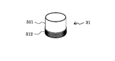
- the voice coil 31 is configured by winding a coil wire rod 312 having a desired diameter around the outer peripheral end of a cylindrical coil bobbin 311 with a desired number of turns.
- the magnetic circuit 32 has a shape corresponding to driving the voice coil 31, and the most commonly used general structure is a ring-shaped ferrite magnet 321.
- the plate 324 is arranged and mounted on the upper surface of the cylindrical ferrite magnet 321 and the disk portion of the yoke 322 provided with the columnar pole 323 is arranged and mounted on the lower surface of the ferrite magnet 321. Is formed by. That is, since the pole 323 and the plate 324 are mounted so that the outer diameter of the pole 323 and the inner diameter of the plate hole 324a are aligned with each other, a predetermined position is provided between the outer surface of the pole 323 and the inner surface of the hole 324a at the center of the plate 324. A ring-shaped gap having a width dimension, that is, a gap 33 is formed.
- the dimension of the gap 33 in the depth direction is determined by the thickness dimension of the plate 324. Therefore, the magnetism of the ferrite magnet 321 is guided to the gap 33 by the yoke 322 and the plate 324 and converged, so that a magnetic flux is generated in the gap 33 and a magnetic gap is formed. Then, the voice coil 31 is arranged at the center of the ring-shaped magnetic gap 33.
- the voice coil 31 is inserted into a hole (hereinafter, referred to as “neck portion”) 1a having a predetermined size provided in the center portion thereof, and the neck portion 1a is inserted.
- neck portion a hole having a predetermined size provided in the center portion thereof
- the neck portion 1a is inserted.
- the coil bobbin 311 is connected and fixed to the driver unit 3.
- the curved diaphragm 2 can be connected and fixed to the tip of the coil bobbin 311 by a predetermined means, for example, as shown in FIGS. 5 to 12.
- a notch 313 is provided at the tip of the voice coil 31, one end side 2a of the curved diaphragm 2 is inserted into the notch 313, and the curved diaphragm 2 is fixed to fix the curved diaphragm 2. 2 and the driver unit 3 (voice coil 31) can be directly connected.
- the notch 313 is provided so that the end surface of the curved diaphragm 2 on one end side 2a is in contact with the voice coil 31 at a substantially right angle in order to efficiently transmit the vibration from the driver unit 3 to the curved diaphragm 1. desirable.
- the curved diaphragm 2 has one end side 2a coated with an adhesive in two notches 313 and 313 provided on a horizontal straight line passing through the center of the voice coil 31 (coil bobbin 311). By inserting it, the state of being connected and fixed to the driver unit 3 is shown.
- the center cap (dust cap) 4 is covered and fixed to the tip of the voice coil 31, and the curved diaphragm 2 is fixed to the center of the center cap 4, so that the curved diaphragm 2 is fixed.
- the driver unit 3 can be directly connected. This means ensures that the curved diaphragm 2 and the driver unit 3 (voice coil 31) are as compared to the above-mentioned means in which a notch 313 is provided at the tip of the voice coil 31 and one end side 2a of the curved diaphragm 2 is inserted. It is desirable in that it can be connected to.
- the center cap (dust cap) 4 is a member that is attached to prevent dust from entering the coil bobbin 311.
- the same material as cone paper is used to enhance the sense of unity of tone, and a metal-based material is used. It can have the role of a dome tweeter.
- one end side 2a is bent downward to form a glue margin, and one surface (glue margin) coated with an adhesive is coated on the tip of a voice coil 31 (coil bobbin 311).
- the cap 4 is connected and fixed to the driver unit 3 by being attached to the surface of the cap 4.
- the surface of the center cap 4 is made flat, and the curved diaphragm 2 is in contact with the tip of the center cap 4 at a substantially right angle in order to efficiently transmit the vibration from the driver unit 3 to the curved diaphragm 1. It is desirable to bend and attach one end side 2a to the surface.
- a notch 41 is provided in the center of the center cap (dust cap) 4 coated on the tip of the voice coil 31, and one end side 2a of the curved diaphragm 2 is inserted into the notch 41.
- the curved diaphragm 2 and the driver unit 3 can be directly connected.
- This means also has a curved diaphragm 2 and a driver unit 3 (voice coil 31) as compared with the above-mentioned means in which a notch 313 is provided at the tip of the voice coil 31 and one end side 2a of the curved diaphragm 2 is inserted. It is desirable because it can be connected securely.
- the curved diaphragm 2 is formed by inserting an adhesive-coated one end side 2a into a notch 41 provided at a position on a horizontal straight line passing through the center of a voice coil 31 (coil bobbin 311). , The state of being connected and fixed to the driver unit 3 is shown.
- the one end side 2a of the curved diaphragm 2 may be folded back toward the back side of the center cap 4 after being inserted into the notch 41. As a result, it is possible to minimize the possibility that the one end side 2a of the curved diaphragm 2 will fall out of the notch 41.
- the tip of the voice coil 31 is covered with a sub-cone 5 and fixed, and the curved diaphragm 2 is fixed in the center of the sub-cone 5, whereby the curved diaphragm 2 and the driver unit 3 (voice). It can be directly connected to the coil 31).
- This means also secures the curved diaphragm 2 and the driver unit 3 (voice coil 31) as compared with the above-mentioned means in which a notch 313 is provided at the tip of the voice coil 31 and one end side 2a of the curved diaphragm 2 is inserted. It is desirable in that it can be connected to.
- the curved diaphragm 2 can be easily attached, and the treble range emitted from the sub-cone 5 itself directly attached to the tip of the voice coil 31 (coil bobbin 311) together with the cone-shaped diaphragm 1 can be generated. It can be stretched.
- one end side 2a is bent downward to form a glue margin, and one surface (glue margin) coated with an adhesive is coated on the tip of a voice coil 31 (coil bobbin 311).
- a state in which the driver unit 3 is connected and fixed by being attached to the surface of the driver unit 3 is shown.
- the curved diaphragm 2 is attached to the surface of the center cap 4, and the curved diaphragm 2 is the tip of the sub-cone 5 in order to efficiently transmit the vibration from the driver unit 3 to the curved diaphragm 1. It is desirable to bend and attach the one end side 2a so as to be in contact with the object at a substantially right angle.
- the curved diaphragm 2 may be attached to the driver unit 3 by attaching reinforcing plates 21, 22, 23 to one surface of one end side 2a.
- the resonance of the curved diaphragm 2 is reduced, and the curved diaphragm 2 can be easily and firmly attached to the voice coil 31 (center cap 4, subcone 5, etc.). Can be.
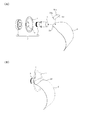
- FIG. 9A a reinforcing plate 21 having one end side bent upward is attached to the upper surface of the curved diaphragm 2 having one end side 2a bent downward, and one surface (glue) formed by bending the reinforcing plate 21.
- a state is shown in which an adhesive is applied to the substitute) and attached to the surface of the center cap 4 that covers the tip of the voice coil 31 (coil bobbin 311).
- FIG. 9B shows a state in which the curved diaphragm 2 with the reinforcing plate 21 is attached to the surface of the center cap 4 exposed at the center of the cone diaphragm 1 and connected and fixed to the driver unit 3. ing.
- a reinforcing plate 21 is attached to the upper surface of the curved diaphragm 2 on one end side 2a, and one end of the curved diaphragm 2 together with the reinforcing plate 21 is inserted into the notch 41 provided in the center of the center cap 4.
- the state in which the side 2a is inserted is shown.
- FIG. 10B one end side 2a of the curved diaphragm 2 with the reinforcing plate 21 coated with the adhesive is inserted into the notch 41 of the center cap 4 exposed at the center of the cone diaphragm 1 and attached. However, the state of being connected and fixed to the driver unit 3 is shown.
- FIG. 11A one surface formed by attaching a reinforcing plate 21 having one end side bent upward to the upper surface of the curved diaphragm 2 having one end side 2a bent downward and having the one end side bent upward.
- the state in which the adhesive is applied to (glue allowance) and attached to the surface of the sub-cone 5 covering the tip of the voice coil 31 (coil bobbin 311) is shown.
- FIG. 11B shows a state in which the curved diaphragm 2 with the reinforcing plate 21 is attached to the surface of the sub-cone 5 exposed at the center of the cone diaphragm 1 and connected and fixed to the driver unit 3. There is.
- a reinforcing plate 23 having a side edge portion 23a bent upward was attached to the upper surface of the curved diaphragm 2 having one end side 2a bent downward, and was formed by bending.
- a state in which an adhesive is applied to one surface (glue allowance) and the end surface of one end side 2a and attached to the surface of the center cap 4 and the surface of the cone diaphragm 1 covering the tip of the voice coil 31 (coil bobbin 311) has been done. Further, in FIG.
- the curved diaphragm 2 with the reinforcing plate 23 is attached to the surface of the center cap 4 exposed at the center of the cone diaphragm 1 and the surface of the cone diaphragm 1 to the driver unit 3. The state where the connection is fixed is shown.
- the small diameter side 1a of the cone diaphragm 1 and the end surface of one end side 2a of the curved diaphragm 2 are both connected to the driver unit 3 (voice coil 31), and the driver unit 3 is electrically connected.
- the voice coil 31 causes vibration accompanying the applied signal, and the vibration is transmitted to the cone diaphragm 1 and the curved diaphragm 2 connected to the voice coil to drive them together. ing.
- the voice coil 31 since one end (base end portion) of the voice coil 31 is housed in the magnetic circuit (magnetic field) 32 and the other end (tip portion) is connected to the cone diaphragm 1 and the curved diaphragm 2.
- the input electric signal moves the voice coil 31, and the movement is transmitted to the cone diaphragm 1 and the curved diaphragm 2 and converted into acoustic energy (sound).
- the direction in which the curved diaphragm 2 is driven by the driver unit 3 is the spreading direction on the surface of the curved diaphragm 2, that is, the other end side 1b (or the other) facing from one end side 1a of the curved diaphragm 1. It refers to the bending direction in which the curved surface portion expands from the end side 1b toward the opposite end side 1a).
- the curved diaphragm 2 is curved in a bow shape when viewed from the side surface (cross section).
- the speaker unit 10 can be a speaker unit 20 having a different form by being attached to the support member 51. That is, the small diameter side 1a of the cone diaphragm 1 and the one end side 2a end surface of the curved diaphragm 2 are connected to the driver unit 3 (voice coil 31), and the large diameter side 1b of the cone diaphragm 1 and the curved diaphragm 2 are connected. The other end side 2b of the above is connected to the support member 51.
- the support member 51 is composed of a flat plate-shaped support plate 511, a convex portion 512 protruding from one surface of the support plate 511, and a wide eaves-shaped support leg 513 provided on the convex portion 512. There is.
- the support plate 511 is provided with an opening (not shown) above which the back side of the cone diaphragm 1 can be inserted, and a cone support frame 9 to which the large diameter side 1b of the cone diaphragm 1 is connected is attached around the opening. As a result, the large diameter side 1b of the cone diaphragm 1 is connected to the support member 51 by the support plate 511.
- the support plate 511 has a vertically long rectangular shape, but the shape is not particularly limited.
- the convex portion 512 supports the support leg 513 to which the other end side 2b of the curved diaphragm 2 is attached, but the protruding front surface 512a is curved so as not to interfere with the attachment of the curved diaphragm 2 (do not collide). It has a curved surface that draws an arc that is substantially equal to the curvature of the diaphragm 2. Therefore, on the back surface side of the curved diaphragm 2, the front surface 512a of the convex portion 512 is located without being in contact with the back surface of the curved diaphragm 2.
- the convex portion 512 functions as an aid to prevent the curved diaphragm 2 from being deformed by an external force from the front surface side.
- the back surface 512b of the convex portion 512 is not entirely attached to the support plate 511, but as shown in FIG. 15, the back surface 512b region located on the sound emitting side of the cone diaphragm 1 is
- the cone diaphragm 1 has an appropriate gap that does not come into contact with the large diameter side 1b so as not to interfere with the vibration of the cone diaphragm 1.
- the convex portion 512 projects only one in the vertical direction in an arc shape at the center of the front surface of the support plate 511 so that the sound emitted from the cone diaphragm 1 is not interrupted. As a result, the sound generated from the cone diaphragm 1 is emitted through both sides of the convex portion 512. If there is no problem in emitting sound from the cone diaphragm 1, a plurality of convex portions 512 may be provided.
- the support leg 513 holds the other end side 2b of the attached curved diaphragm 2, but has a concave groove 513a on the upper surface along the width direction.
- the other end side 2b of the curved diaphragm 2 is connected to the support member 51 by the support leg 513.
- the small diameter side 1a of the cone diaphragm 1 and the end surface of one end side 2a of the curved diaphragm 2 are connected to the driver unit 3 (voice coil 31), and the diameter of the cone diaphragm 1 is
- the large side 1b and the other end side 2b of the curved diaphragm 2 are connected to the support member 51. Therefore, the cone diaphragm 1, the curved diaphragm 2, and the driver unit 3 are stably supported by the support member 51, are easily transported, and can be easily mounted on the housing.
- the speaker 100 is configured to include at least a cone diaphragm 1, a curved diaphragm 2, a driver unit 3, and a housing 50.
- a dynamic type first speaker provided with the cone diaphragm 1 and a second speaker provided with the curved diaphragm 2
- both the hearing-impaired person and the normal hearing person can hear each other. ..
- the housing 50 is a box-shaped hollow structure that accommodates the cone diaphragm 1, the curved diaphragm 2, and the driver unit 3, and is a mounted first speaker (cone diaphragm 1) or a second speaker.
- the front region emitted from the (curved diaphragm 2) has a skeleton structure having an open portion formed by a frame.
- the housing 50 has a structure composed of six surfaces of a front plate, a back plate, a right side plate, a left side plate, a top plate, and a bottom plate. Then, the first speaker unit 10 is attached to the front plate of the housing 50.
- the support plate 511 of the support member 51 on which the cone diaphragm 1, the curved diaphragm 2, and the driver unit 3 are mounted is the housing 50. It can be installed as a front plate of.
- the cone diaphragm 1 mounted on the housing 50 has a large diameter side 1b connected to the support plate 511 of the support member 51 forming a part of the housing 50.
- the other end side 2b of the curved diaphragm 2 is connected to the support leg 513 of the support member 51 forming a part of the housing 50.
- the open portion in this case will be described in front of the front plate constituting the housing 50, specifically, the front surface and the upper surface in the region from the support plate 511 to the support leg 513 of the support member 51 functioning as the front plate. And the left and right sides are open.
- This open portion is designed so that the sound generated from the cone diaphragm 1 and the curved diaphragm 2 is effectively emitted to the outside without being muffled.
- the speaker 100 configured as described above has higher performance, is lighter, and has a smaller installation area than the conventional speaker system for hearing-impaired and hearing-impaired people. It is possible to obtain a hybrid speaker system in which the number of speakers is reduced, the versatility of the speaker is further improved, and both the hearing-impaired and the hearing-impaired can listen with satisfaction.
- an audio signal output from a television, a radio, an audio player, a personal computer, a smart device such as a smartphone or a tablet, or the like can be mentioned.
- the back plate portion of the housing 50 is provided with holes for mounting an audio jack and a switch.
- the sound from the dynamic type first speaker provided with the cone-shaped diaphragm and the sound from the second speaker provided with the curved diaphragm are mixed to obtain a wide band sound (for the hearing impaired and for the hearing impaired). It is possible to reproduce sound waves for normal hearing people. Further, since the driver unit for driving the cone-shaped diaphragm and the driver unit for driving the curved diaphragm are shared, the manufacturing cost and the weight are reduced. Further, by integrally connecting the first speaker and the second speaker, the installation area can be reduced and the size can be reduced.
- 1 1st diaphragm (cone-shaped diaphragm), 1a small diameter side, 1b large diameter side, 2 2nd diaphragm (curved diaphragm), 2a one end side, 2b other end side, 3 driver unit, 4 center Cap (dust cap), 5 sub-cone, 9-cone support frame, 10 speaker unit, 21, 22, 23 reinforcing plate, 31 voice coil, 32 magnetic circuit, 41, 51 notch, 50 housing, 51 support member, 100 speaker ( Hybrid speaker system), 511 support plate (front plate), 512 convex parts, 513 support legs.
Landscapes
- Engineering & Computer Science (AREA)
- Physics & Mathematics (AREA)
- Acoustics & Sound (AREA)
- Signal Processing (AREA)
- Multimedia (AREA)
- Health & Medical Sciences (AREA)
- Otolaryngology (AREA)
- Audible-Bandwidth Dynamoelectric Transducers Other Than Pickups (AREA)
- Diaphragms For Electromechanical Transducers (AREA)
- Obtaining Desirable Characteristics In Audible-Bandwidth Transducers (AREA)
Priority Applications (13)
| Application Number | Priority Date | Filing Date | Title |
|---|---|---|---|
| US17/635,793 US12063468B2 (en) | 2019-08-17 | 2019-08-17 | Speaker unit and speaker |
| KR1020227003008A KR102625408B1 (ko) | 2019-08-17 | 2019-08-17 | 스피커유닛 및 스피커 만곡진동판 |
| JP2021541349A JP7369195B2 (ja) | 2019-08-17 | 2019-08-17 | スピーカ |
| PH1/2022/550228A PH12022550228A1 (en) | 2019-08-17 | 2019-08-17 | Speaker unit and speaker |
| MX2022002028A MX2022002028A (es) | 2019-08-17 | 2019-08-17 | Unidad de altavoz y altavoz. |
| CA3147331A CA3147331C (en) | 2019-08-17 | 2019-08-17 | Speaker unit and speaker |
| EP19942086.0A EP4017025A4 (en) | 2019-08-17 | 2019-08-17 | SPEAKER UNIT AND CURVED SPEAKER MEMBRANE |
| EP25156375.5A EP4529226B1 (en) | 2019-08-17 | 2019-08-17 | Speaker unit and speaker curved diaphragm |
| KR1020237041600A KR102759777B1 (ko) | 2019-08-17 | 2019-08-17 | 스피커유닛 및 스피커 |
| CN201980099404.1A CN114223213B (zh) | 2019-08-17 | 2019-08-17 | 扬声器单元及扬声器 |
| BR112022001254-3A BR112022001254B1 (pt) | 2019-08-17 | Unidade de alto-falante e alto-falante | |
| AU2019462145A AU2019462145B2 (en) | 2019-08-17 | 2019-08-17 | Speaker unit and speaker curved diaphragm |
| PCT/JP2019/032203 WO2021033226A1 (ja) | 2019-08-17 | 2019-08-17 | スピーカユニット、及びスピーカ湾曲振動板 |
Applications Claiming Priority (1)
| Application Number | Priority Date | Filing Date | Title |
|---|---|---|---|
| PCT/JP2019/032203 WO2021033226A1 (ja) | 2019-08-17 | 2019-08-17 | スピーカユニット、及びスピーカ湾曲振動板 |
Publications (1)
| Publication Number | Publication Date |
|---|---|
| WO2021033226A1 true WO2021033226A1 (ja) | 2021-02-25 |
Family
ID=74659881
Family Applications (1)
| Application Number | Title | Priority Date | Filing Date |
|---|---|---|---|
| PCT/JP2019/032203 Ceased WO2021033226A1 (ja) | 2019-08-17 | 2019-08-17 | スピーカユニット、及びスピーカ湾曲振動板 |
Country Status (10)
| Country | Link |
|---|---|
| US (1) | US12063468B2 (https=) |
| EP (2) | EP4529226B1 (https=) |
| JP (1) | JP7369195B2 (https=) |
| KR (2) | KR102625408B1 (https=) |
| CN (1) | CN114223213B (https=) |
| AU (1) | AU2019462145B2 (https=) |
| CA (1) | CA3147331C (https=) |
| MX (1) | MX2022002028A (https=) |
| PH (1) | PH12022550228A1 (https=) |
| WO (1) | WO2021033226A1 (https=) |
Families Citing this family (3)
| Publication number | Priority date | Publication date | Assignee | Title |
|---|---|---|---|---|
| JP7025833B2 (ja) * | 2019-09-17 | 2022-02-25 | 株式会社サウンドファン | スピーカユニット、及びスピーカ |
| CN116320924A (zh) * | 2023-03-03 | 2023-06-23 | 江西融贤声学科技有限公司 | 拓扑曲面带扬声器 |
| WO2025194373A1 (zh) * | 2024-03-20 | 2025-09-25 | 瑞声光电科技(常州)有限公司 | 扬声器 |
Citations (5)
| Publication number | Priority date | Publication date | Assignee | Title |
|---|---|---|---|---|
| JP5668233B1 (ja) | 2014-03-26 | 2015-02-12 | 株式会社サウンドファン | 万能スピーカ |
| JP2015188195A (ja) * | 2014-09-10 | 2015-10-29 | 株式会社サウンドファン | 万能スピーカ |
| JP2015233272A (ja) * | 2014-05-14 | 2015-12-24 | ヤマハ株式会社 | 電気音響変換器 |
| JP2016140060A (ja) | 2015-01-25 | 2016-08-04 | 株式会社サウンドファン | 万能スピーカ |
| US20160353206A1 (en) * | 2015-06-01 | 2016-12-01 | Alexander Manly STAHL | Audio transducer with hybrid diaphragm |
Family Cites Families (15)
| Publication number | Priority date | Publication date | Assignee | Title |
|---|---|---|---|---|
| US5418336A (en) * | 1990-10-17 | 1995-05-23 | Canon Research Centre Europe Ltd. | Sound output device |
| GB9215222D0 (en) * | 1992-07-17 | 1992-09-02 | Electro Acoustic Ind Ltd | Loudspeaker |
| GB9714050D0 (en) * | 1997-07-03 | 1997-09-10 | New Transducers Ltd | Panel-form loudspeakers |
| JP2006303777A (ja) * | 2005-04-19 | 2006-11-02 | Pioneer Electronic Corp | スピーカ装置 |
| JP2008131541A (ja) * | 2006-11-24 | 2008-06-05 | Yamaha Corp | スピーカ装置 |
| JP2013157798A (ja) * | 2012-01-30 | 2013-08-15 | Panasonic Corp | スピーカ、補聴器、インナーイヤーヘッドホン、携帯型情報処理装置、およびav機器 |
| JP6048469B2 (ja) * | 2013-10-22 | 2016-12-21 | ヤマハ株式会社 | 電気音響変換器 |
| FR3014628B1 (fr) * | 2013-12-05 | 2017-04-21 | Devialet | Haut-parleur electrodynamique compact a membrane convexe |
| JP6123838B2 (ja) * | 2014-09-29 | 2017-05-10 | ヤマハ株式会社 | 電気音響変換器 |
| JP2016096454A (ja) * | 2014-11-14 | 2016-05-26 | ヤマハ株式会社 | 電気音響変換器 |
| KR20160140060A (ko) | 2015-05-29 | 2016-12-07 | 부경대학교 산학협력단 | 수질 모니터링 시스템 및 이를 이용한 수질 모니터링 방법 |
| GB2542382A (en) * | 2015-09-17 | 2017-03-22 | Gp Acoustics (Uk) Ltd | Low-profile loudspeaker |
| JP6418556B2 (ja) * | 2015-12-17 | 2018-11-07 | オンキヨー株式会社 | スピーカー用振動板、これを備えたスピーカー、および、スピーカー用振動板の製造方法 |
| JP6439894B1 (ja) * | 2018-07-16 | 2018-12-19 | 株式会社サウンドファン | スピーカ湾曲振動板 |
| JP7816876B2 (ja) * | 2022-04-26 | 2026-02-18 | パナソニックオートモーティブシステムズ株式会社 | 副振動板、およびスピーカ |
-
2019
- 2019-08-17 KR KR1020227003008A patent/KR102625408B1/ko active Active
- 2019-08-17 WO PCT/JP2019/032203 patent/WO2021033226A1/ja not_active Ceased
- 2019-08-17 CA CA3147331A patent/CA3147331C/en active Active
- 2019-08-17 PH PH1/2022/550228A patent/PH12022550228A1/en unknown
- 2019-08-17 JP JP2021541349A patent/JP7369195B2/ja active Active
- 2019-08-17 EP EP25156375.5A patent/EP4529226B1/en active Active
- 2019-08-17 EP EP19942086.0A patent/EP4017025A4/en active Pending
- 2019-08-17 MX MX2022002028A patent/MX2022002028A/es unknown
- 2019-08-17 US US17/635,793 patent/US12063468B2/en active Active
- 2019-08-17 CN CN201980099404.1A patent/CN114223213B/zh active Active
- 2019-08-17 AU AU2019462145A patent/AU2019462145B2/en active Active
- 2019-08-17 KR KR1020237041600A patent/KR102759777B1/ko active Active
Patent Citations (5)
| Publication number | Priority date | Publication date | Assignee | Title |
|---|---|---|---|---|
| JP5668233B1 (ja) | 2014-03-26 | 2015-02-12 | 株式会社サウンドファン | 万能スピーカ |
| JP2015233272A (ja) * | 2014-05-14 | 2015-12-24 | ヤマハ株式会社 | 電気音響変換器 |
| JP2015188195A (ja) * | 2014-09-10 | 2015-10-29 | 株式会社サウンドファン | 万能スピーカ |
| JP2016140060A (ja) | 2015-01-25 | 2016-08-04 | 株式会社サウンドファン | 万能スピーカ |
| US20160353206A1 (en) * | 2015-06-01 | 2016-12-01 | Alexander Manly STAHL | Audio transducer with hybrid diaphragm |
Also Published As
| Publication number | Publication date |
|---|---|
| PH12022550228A1 (en) | 2022-12-12 |
| CN114223213A (zh) | 2022-03-22 |
| EP4017025A4 (en) | 2023-05-24 |
| CA3147331C (en) | 2023-06-27 |
| EP4529226A3 (en) | 2025-06-11 |
| MX2022002028A (es) | 2022-03-11 |
| AU2019462145B2 (en) | 2023-04-06 |
| AU2019462145A1 (en) | 2022-03-03 |
| EP4529226A2 (en) | 2025-03-26 |
| KR20220025035A (ko) | 2022-03-03 |
| KR102759777B1 (ko) | 2025-01-24 |
| BR112022001254A2 (pt) | 2022-04-05 |
| KR20230169451A (ko) | 2023-12-15 |
| JPWO2021033226A1 (https=) | 2021-02-25 |
| US12063468B2 (en) | 2024-08-13 |
| EP4529226C0 (en) | 2026-02-11 |
| CA3147331A1 (en) | 2021-02-25 |
| EP4529226B1 (en) | 2026-02-11 |
| KR102625408B1 (ko) | 2024-01-15 |
| JP7369195B2 (ja) | 2023-10-25 |
| US20220295173A1 (en) | 2022-09-15 |
| EP4017025A1 (en) | 2022-06-22 |
| CN114223213B (zh) | 2024-12-13 |
Similar Documents
| Publication | Publication Date | Title |
|---|---|---|
| JP6586702B1 (ja) | スピーカユニット、及びスピーカ湾曲振動板 | |
| WO2021033226A1 (ja) | スピーカユニット、及びスピーカ湾曲振動板 | |
| JPWO2021033226A5 (https=) | ||
| TWI871354B (zh) | 揚聲器單元及揚聲器 | |
| KR102911723B1 (ko) | 스피커 유닛 및 스피커 만곡진동판 | |
| JP6439894B1 (ja) | スピーカ湾曲振動板 | |
| JP7114827B1 (ja) | スピーカユニット、及びスピーカ湾曲振動板 | |
| TWI804679B (zh) | 揚聲器單元及揚聲器 | |
| JP7114826B1 (ja) | スピーカユニット、及びスピーカ湾曲振動板 | |
| JP7214090B1 (ja) | スピーカユニット、及びスピーカ湾曲振動板 | |
| RU2779044C1 (ru) | Блок громкоговорителя и громкоговоритель | |
| HK40064655A (en) | Speaker unit and speaker | |
| HK40065135B (zh) | 扬声器单元及扬声器 | |
| HK40065135A (en) | Speaker unit and speaker | |
| HK40064655B (zh) | 扬声器单元及扬声器 | |
| JP2020077925A (ja) | スピーカ、スピーカユニット及び振動板 |
Legal Events
| Date | Code | Title | Description |
|---|---|---|---|
| 121 | Ep: the epo has been informed by wipo that ep was designated in this application |
Ref document number: 19942086 Country of ref document: EP Kind code of ref document: A1 |
|
| ENP | Entry into the national phase |
Ref document number: 3147331 Country of ref document: CA |
|
| ENP | Entry into the national phase |
Ref document number: 20227003008 Country of ref document: KR Kind code of ref document: A |
|
| REG | Reference to national code |
Ref country code: BR Ref legal event code: B01A Ref document number: 112022001254 Country of ref document: BR |
|
| NENP | Non-entry into the national phase |
Ref country code: DE |
|
| ENP | Entry into the national phase |
Ref document number: 2019462145 Country of ref document: AU Date of ref document: 20190817 Kind code of ref document: A |
|
| WWE | Wipo information: entry into national phase |
Ref document number: 2022102648 Country of ref document: RU Ref document number: 2019942086 Country of ref document: EP |
|
| ENP | Entry into the national phase |
Ref document number: 2019942086 Country of ref document: EP Effective date: 20220317 |
|
| ENP | Entry into the national phase |
Ref document number: 112022001254 Country of ref document: BR Kind code of ref document: A2 Effective date: 20220124 |
|
| ENP | Entry into the national phase |
Ref document number: 2021541349 Country of ref document: JP Kind code of ref document: A |
|
| WWG | Wipo information: grant in national office |
Ref document number: MX/A/2022/002028 Country of ref document: MX |