WO2021031077A1 - Procédé et dispositif d'émission de signal, procédé et dispositif de traitement de signal, et système radar - Google Patents
Procédé et dispositif d'émission de signal, procédé et dispositif de traitement de signal, et système radar Download PDFInfo
- Publication number
- WO2021031077A1 WO2021031077A1 PCT/CN2019/101409 CN2019101409W WO2021031077A1 WO 2021031077 A1 WO2021031077 A1 WO 2021031077A1 CN 2019101409 W CN2019101409 W CN 2019101409W WO 2021031077 A1 WO2021031077 A1 WO 2021031077A1
- Authority
- WO
- WIPO (PCT)
- Prior art keywords
- burst
- measurement frame
- transmitting
- echo signal
- speed
- Prior art date
Links
Images


Classifications
-
- G—PHYSICS
- G01—MEASURING; TESTING
- G01S—RADIO DIRECTION-FINDING; RADIO NAVIGATION; DETERMINING DISTANCE OR VELOCITY BY USE OF RADIO WAVES; LOCATING OR PRESENCE-DETECTING BY USE OF THE REFLECTION OR RERADIATION OF RADIO WAVES; ANALOGOUS ARRANGEMENTS USING OTHER WAVES
- G01S7/00—Details of systems according to groups G01S13/00, G01S15/00, G01S17/00
- G01S7/003—Transmission of data between radar, sonar or lidar systems and remote stations
- G01S7/006—Transmission of data between radar, sonar or lidar systems and remote stations using shared front-end circuitry, e.g. antennas
-
- G—PHYSICS
- G01—MEASURING; TESTING
- G01S—RADIO DIRECTION-FINDING; RADIO NAVIGATION; DETERMINING DISTANCE OR VELOCITY BY USE OF RADIO WAVES; LOCATING OR PRESENCE-DETECTING BY USE OF THE REFLECTION OR RERADIATION OF RADIO WAVES; ANALOGOUS ARRANGEMENTS USING OTHER WAVES
- G01S13/00—Systems using the reflection or reradiation of radio waves, e.g. radar systems; Analogous systems using reflection or reradiation of waves whose nature or wavelength is irrelevant or unspecified
- G01S13/02—Systems using reflection of radio waves, e.g. primary radar systems; Analogous systems
- G01S13/06—Systems determining position data of a target
- G01S13/08—Systems for measuring distance only
- G01S13/32—Systems for measuring distance only using transmission of continuous waves, whether amplitude-, frequency-, or phase-modulated, or unmodulated
- G01S13/34—Systems for measuring distance only using transmission of continuous waves, whether amplitude-, frequency-, or phase-modulated, or unmodulated using transmission of continuous, frequency-modulated waves while heterodyning the received signal, or a signal derived therefrom, with a locally-generated signal related to the contemporaneously transmitted signal
- G01S13/343—Systems for measuring distance only using transmission of continuous waves, whether amplitude-, frequency-, or phase-modulated, or unmodulated using transmission of continuous, frequency-modulated waves while heterodyning the received signal, or a signal derived therefrom, with a locally-generated signal related to the contemporaneously transmitted signal using sawtooth modulation
-
- G—PHYSICS
- G01—MEASURING; TESTING
- G01S—RADIO DIRECTION-FINDING; RADIO NAVIGATION; DETERMINING DISTANCE OR VELOCITY BY USE OF RADIO WAVES; LOCATING OR PRESENCE-DETECTING BY USE OF THE REFLECTION OR RERADIATION OF RADIO WAVES; ANALOGOUS ARRANGEMENTS USING OTHER WAVES
- G01S13/00—Systems using the reflection or reradiation of radio waves, e.g. radar systems; Analogous systems using reflection or reradiation of waves whose nature or wavelength is irrelevant or unspecified
- G01S13/02—Systems using reflection of radio waves, e.g. primary radar systems; Analogous systems
- G01S13/50—Systems of measurement based on relative movement of target
- G01S13/58—Velocity or trajectory determination systems; Sense-of-movement determination systems
- G01S13/583—Velocity or trajectory determination systems; Sense-of-movement determination systems using transmission of continuous unmodulated waves, amplitude-, frequency-, or phase-modulated waves and based upon the Doppler effect resulting from movement of targets
- G01S13/584—Velocity or trajectory determination systems; Sense-of-movement determination systems using transmission of continuous unmodulated waves, amplitude-, frequency-, or phase-modulated waves and based upon the Doppler effect resulting from movement of targets adapted for simultaneous range and velocity measurements
-
- G—PHYSICS
- G01—MEASURING; TESTING
- G01S—RADIO DIRECTION-FINDING; RADIO NAVIGATION; DETERMINING DISTANCE OR VELOCITY BY USE OF RADIO WAVES; LOCATING OR PRESENCE-DETECTING BY USE OF THE REFLECTION OR RERADIATION OF RADIO WAVES; ANALOGOUS ARRANGEMENTS USING OTHER WAVES
- G01S13/00—Systems using the reflection or reradiation of radio waves, e.g. radar systems; Analogous systems using reflection or reradiation of waves whose nature or wavelength is irrelevant or unspecified
- G01S13/88—Radar or analogous systems specially adapted for specific applications
- G01S13/93—Radar or analogous systems specially adapted for specific applications for anti-collision purposes
- G01S13/931—Radar or analogous systems specially adapted for specific applications for anti-collision purposes of land vehicles
-
- G—PHYSICS
- G01—MEASURING; TESTING
- G01S—RADIO DIRECTION-FINDING; RADIO NAVIGATION; DETERMINING DISTANCE OR VELOCITY BY USE OF RADIO WAVES; LOCATING OR PRESENCE-DETECTING BY USE OF THE REFLECTION OR RERADIATION OF RADIO WAVES; ANALOGOUS ARRANGEMENTS USING OTHER WAVES
- G01S7/00—Details of systems according to groups G01S13/00, G01S15/00, G01S17/00
- G01S7/02—Details of systems according to groups G01S13/00, G01S15/00, G01S17/00 of systems according to group G01S13/00
- G01S7/35—Details of non-pulse systems
- G01S7/352—Receivers
- G01S7/354—Extracting wanted echo-signals
-
- H—ELECTRICITY
- H04—ELECTRIC COMMUNICATION TECHNIQUE
- H04B—TRANSMISSION
- H04B7/00—Radio transmission systems, i.e. using radiation field
- H04B7/02—Diversity systems; Multi-antenna system, i.e. transmission or reception using multiple antennas
- H04B7/04—Diversity systems; Multi-antenna system, i.e. transmission or reception using multiple antennas using two or more spaced independent antennas
- H04B7/0413—MIMO systems
Definitions
- This application relates to the field of sensor technology, and in particular to a signal transmission method and device, a signal processing method and device, and a radar system.
- Vehicle-mounted radar is an indispensable sensor in the automatic driving system.
- the vehicle-mounted radar can provide obstacle (also known as target) detection for the vehicle. Specifically, the distance, speed, and azimuth of obstacles around the vehicle can be detected.
- the frequency band has gradually evolved from 24GHz to 77GHz/79GHz, so as to obtain higher range resolution through larger scanning bandwidth; the number of channels is changed from single input multiple output (SIMO)
- SIMO single input multiple output
- MIMO multiple input multiple output
- multiple antennas can use time division multiplexing (TDM) to transmit chirp signals.
- TDM time division multiplexing
- the maximum speed range of MIMO radar is reduced.
- Tc_SIMO which can be called a time slot.
- the relationship between the maximum speed measurement range Vmax_MIMO when using Nt antennas to transmit chirp and the maximum speed measurement range Vmax_SIMO (that is, the speed measurement range of SIMO radar) when using a single antenna to transmit chirp can be expressed as: Vmax_SIMO ⁇ Nt*Vmax_MIMO.
- the embodiments of the present application provide a signal transmission method and device, a signal processing method and device, and a radar system, so that the MIMO radar can accurately restore the speed of the target to the speed measurement range of the SIMO radar.
- an embodiment of the present application provides a signal transmission method, which is applied to a multiple-input multiple-output MIMO radar.
- the MIMO radar includes a transmitter, and the transmitter includes multiple transmitting antennas.
- the signal transmission method includes: The first burst in a measurement frame. The first measurement frame is used to measure the speed of the target. When the first burst is sent, each of the multiple transmitting antennas transmits the chirp signal in a time-sharing manner; After the first burst in the first measurement frame, the transmitter sends the second burst in the first measurement frame. When sending the second burst, the number of transmitting antennas used to send the chirp signal is one.
- the target speed range can be achieved by using the echo signal formed after the reflection of the first burst sent in the MIMO mode and the echo signal formed after the reflection of the second burst sent in the SIMO mode after the first burst. Search to match the speed aliasing coefficient of one or more targets, and restore the speed range of the MIMO radar to the SIMO range. At the same time, it can also reduce the complexity of MIMO spectral peak search and reduce the influence of channel phase noise on overlapping arrays.
- sending the SIMO burst (that is, the second burst) after the MIMO burst (that is, the first burst) can make the fast moving target move to the SIMO.
- the method further includes: the transmitter sends the third burst in the first measurement frame; when the third burst is sent, it is used to transmit the chirp signal.
- the number of antennas is one, the transmitting antenna for transmitting the third burst and the transmitting antenna for transmitting the second burst are the same transmitting antenna; wherein, the transmitter transmits the first measurement frame with a P% duty cycle, P ⁇ 100, The duty cycle is equal to the ratio of the first duration to the second duration.
- the first duration is the duration of the first measurement frame
- the second duration is the time difference between two adjacent measurement frames sent by the transmitter.
- the first burst sent in the middle position is sent in MIMO mode, and its prefix and suffix are sent in SIMO format. Then, after one or more When processing the echo signal formed by the reflection of a target, two bursts sent in the SIMO mode can be selected for speed matching, which makes the calculation of the target speed easier. In addition, it can also alleviate the problem of the scattering center of fast-moving targets moving with the launch time to a certain extent.
- the transmitter sends the first measurement frame with a duty cycle of P%, so in each measurement period, after the measurement frame is sent, there is a certain amount of idle time and processing time, and then the next measurement frame is sent. There is a duty cycle P%.
- the transmitter after the transmitter sends the first measurement frame, it further includes: the transmitter sends the fourth burst in the second measurement frame, the second measurement frame is used to measure the speed of the target, and when the fourth burst is sent, multiple Each of the transmitting antennas sends the chirp signal in a time-sharing manner; after the transmitter sends the fourth burst in the second measurement frame, the transmitter sends the fifth burst in the second measurement frame, and then the fifth burst is sent At this time, the number of transmitting antennas used to transmit the chirp signal is one; the transmission parameters of the fifth burst, the second burst and the third burst are the same.
- the transmission parameters include the transmission slope, the transmission antenna, the number of transmitted chirp signals, the duration of each chirp signal, and so on.
- the number of chirp signals sent by each of the multiple transmitting antennas is different.
- the high-density transmitting antenna can be used to further reduce the complexity of spectral peak search.
- the first measurement frame is any one of FM continuous wave FMCW, multi-frequency shift keying MFSK, or phase-modulated continuous wave PMCW.
- the MIMO radar may also include a processing unit. Then, the method further includes: the processing unit determines the configuration of the first measurement frame, and sends the configuration of the first measurement frame to the monolithic microwave integrated circuit MMIC through the interface, and the MMIC is used for The configuration of the first measurement frame enables the transmitter to send the first measurement frame.
- relevant parameters can be configured for the MMIC, thereby completing the transmission of the first measurement frame.
- the embodiments of the present application also provide a signal processing method, which is applied to a MIMO radar.
- the MIMO radar includes a transmitter, a receiver, and a processing unit, and the transmitter includes multiple transmitting antennas.
- the signal processing method includes: the receiver receives the first echo signal and the second echo signal, the first echo signal is reflected by one or more targets after the first burst in the measurement frame sent by the transmitter Formed, the second echo signal is formed by the second burst in the measurement frame after being reflected by one or more targets.
- the second burst is sent after the first burst; when the first burst is sent, multiple transmit antennas Each transmitting antenna in the transmission antenna transmits the chirp signal in time sharing; when transmitting the second burst, the number of transmitting antennas used to transmit the chirp signal is one; the processing unit determines one or more targets according to the echo signal received by the receiver speed.
- the echo signal formed after the reflection of the first burst sent in the MIMO mode and the echo formed after the reflection of the second burst sent in the SIMO mode after the first burst can be adopted.
- the signal searches for the speed range of the target, so as to match the speed aliasing coefficient of one or more targets, and restore the speed measurement range of the MIMO radar to the SIMO speed measurement range.
- the processing unit determines the speed of one or more targets according to the echo signal received by the receiver, including: the processing unit determines the first identifier according to the first echo signal, and the first identifier is used to indicate a Distance measurement value and speed measurement value of one or more targets; the processing unit determines a second identifier according to the second echo signal, the second identifier is used to indicate the distance measurement value and speed measurement value of one or more targets; An identification and a second identification determine the speed of one or more targets.
- the speed aliasing coefficient of the target can be determined according to the two sets of target identifiers (ie, the first identifier and the second identifier), and then the speed of the target can be determined.
- the processing unit determines the speed of one or more targets according to the first identifier and the second identifier, including: the processing unit determines the corresponding first identifier according to the repetition period transmitted by the first transmitting antenna in the first burst The processing unit determines the aliasing coefficient subset according to the first identifier, the second identifier and the aliasing coefficient interval; the processing unit determines the speed aliasing coefficient according to the aliasing coefficient subset; the processing unit determines the speed aliasing coefficient according to the speed aliasing coefficient and The first identification determines the speed of one or more targets.
- the method further includes: the receiver receives a third echo signal, the third echo signal is formed by the third burst in the aforementioned measurement frame after being reflected by one or more targets, and the third burst is in the first burst.
- the processing unit determines the speed of one or more targets according to the echo signal received by the receiver, including: if one or more targets move away from the radar system, the processing unit according to the first echo signal and the first Three-echo signals determine the speed of one or more targets; if one or more targets move toward the radar system, the processing unit determines the speed of one or more targets according to the first echo signal and the second echo signal .
- the target actually moves on three bursts.
- this movement will affect the signal strength of the received target.
- the distance between the target and the second burst is getting farther and farther, so that the signal strength of the target is reduced, so the data in the third burst is more reliable.
- the distance between the target and the second burst is getting closer, so that the target signal strength increases, and the data in the second burst is more reliable.
- the processing unit determines the velocity aliasing coefficient according to the aliasing coefficient subset, including: the processing unit determines the observation result of the virtual MIMO sub-array according to the echo signal received by the receiver; The observation results of the array determine the velocity aliasing coefficient; among them, the virtual MIMO sub-array is a uniform planar sub-array or uniform line sub-array formed by the virtual array elements in the virtual array, and each transmitting antenna corresponds to the virtual array in the virtual MIMO sub-array The number of elements is the same, and the virtual array is formed by multiple transmitting antennas and multiple receiving antennas included in the receiver.
- a virtual MIMO sub-array can be formed by selecting multiple array elements in the virtual array, and performing FFT on the observation result of the virtual MIMO sub-array to calculate the angle spectrum.
- the processing unit determines the velocity aliasing coefficient according to the aliasing coefficient subset, including: the processing unit determines the observation result of the virtual MIMO sub-array according to the echo signal received by the receiver; The observation results of the array determine the velocity aliasing coefficient; among them, the virtual MIMO sub-array is a planar sub-array or a linear sub-array formed by the virtual array elements in the virtual array, and the uniform planar sub-array and uniform line sub-array obtained by linear interpolation, Each transmitting antenna corresponds to the same number of virtual array elements in the virtual MIMO sub-array, and the virtual array is formed by multiple transmitting antennas and multiple receiving antennas included in the receiver.
- a virtual MIMO sub-array can be formed by linear interpolation.
- an embodiment of the present application provides a signal transmission device, including: a transmitter including a plurality of transmitting antennas for transmitting a first burst in a first measurement frame, and the first measurement frame is used for measurement The speed of the target, when transmitting the first burst, each of the multiple transmitting antennas transmits the chirp signal in time sharing; and, after transmitting the first burst in the first measurement frame, the first measurement is transmitted For the second burst in the frame, when the second burst is sent, the number of transmitting antennas used to send the chirp signal is one.
- the transmitter is also used to: send the third burst in the first measurement frame before sending the first burst in the first measurement frame; when sending the third burst, use Since the number of transmitting antennas for sending chirp signals is one, the transmitting antenna for transmitting the third burst and the transmitting antenna for transmitting the second burst are the same transmitting antenna; wherein, the transmitter transmits the first measurement frame with a P% duty cycle , P ⁇ 100, the duty cycle is equal to the ratio of the first duration to the second duration, the first duration is the duration of the first measurement frame, and the second duration is the time difference between two adjacent measurement frames sent by the transmitter.
- the transmitter is also used to send the fourth burst in the second measurement frame after sending the first measurement frame, the second measurement frame is used to measure the speed of the target, and the fourth
- each of the multiple transmit antennas transmits the chirp signal in a time-sharing manner; after transmitting the fourth burst in the second measurement frame, the fifth burst in the second measurement frame is transmitted, and the fifth burst in the second measurement frame is transmitted.
- the number of transmitting antennas used to transmit a chirp signal is one; the transmission parameters of the fifth burst, the second burst, and the third burst are the same.
- the transmission parameter includes one or more of the following: a transmission slope, a transmission antenna, the number of transmitted chirp signals, or the duration of each chirp signal.
- the first measurement frame is any one of FM continuous wave FMCW, multi-frequency shift keying MFSK, or phase-modulated continuous wave PMCW.
- the device further includes: a processing unit, configured to determine the configuration of the first measurement frame, and send the configuration of the first measurement frame to the monolithic microwave integrated circuit MMIC through the interface, and the MMIC is used for The configuration of a measurement frame enables the transmitter to send the first measurement frame.
- a processing unit configured to determine the configuration of the first measurement frame, and send the configuration of the first measurement frame to the monolithic microwave integrated circuit MMIC through the interface, and the MMIC is used for The configuration of a measurement frame enables the transmitter to send the first measurement frame.
- an embodiment of the present application provides a signal processing device, including: a receiver for receiving a first echo signal and a second echo signal, and the first echo signal in the measurement frame sent by the first echo signal transmitter
- the burst is formed after being reflected by one or more targets
- the second echo signal is formed by the second burst in the measurement frame being reflected by one or more targets
- the second burst is sent after the first burst
- each of the multiple transmit antennas transmits the chirp signal in time sharing; when the second burst is transmitted, the number of transmit antennas used to transmit the chirp signal is one; the processing unit is used for receiving
- the echo signal received by the receiver determines the speed of one or more targets.
- the processing unit determines the speed of one or more targets according to the echo signal received by the receiver, it is specifically used to determine the first identifier according to the first echo signal, and the first identifier is used for Indicate the distance measurement value and speed measurement value of one or more targets; determine the second identifier according to the second echo signal, the second identifier is used to indicate the distance measurement value and speed measurement value of one or more targets; according to the first identifier And the second identification determines the speed of one or more targets.
- the processing unit determines the speed of one or more targets according to the first identifier and the second identifier, it is specifically configured to: determine the first burst according to the repetition period transmitted by the first transmitting antenna in the first burst. Identify the corresponding aliasing coefficient interval; determine the aliasing coefficient subset according to the first identification, the second identification and the aliasing coefficient interval; determine the speed aliasing coefficient according to the aliasing coefficient subset; determine the speed aliasing coefficient and the first identification The speed of one or more targets.
- the receiver is also used to: receive a third echo signal, the third echo signal is formed by reflecting the third burst in the aforementioned measurement frame by one or more targets, and the third burst Send before the first burst; when the processing unit determines the speed of one or more targets according to the echo signals received by the receiver, it is specifically used to: if one or more targets move away from the radar system, then Determine the speed of one or more targets based on the first echo signal and the third echo signal; if one or more targets move closer to the radar system, determine one based on the first echo signal and the second echo signal Or the speed of multiple targets.
- the processing unit determines the velocity aliasing coefficient according to the aliasing coefficient subset, it is specifically used to: determine the observation result of the virtual MIMO sub-array according to the echo signal received by the receiver; The observation results of the array determine the velocity aliasing coefficient; among them, the virtual MIMO sub-array is a uniform planar sub-array or uniform line sub-array formed by the virtual array elements in the virtual array, and each transmitting antenna corresponds to the virtual array in the virtual MIMO sub-array The number of elements is the same, and the virtual array is formed by multiple transmitting antennas and multiple receiving antennas included in the receiver.
- the processing unit determines the velocity aliasing coefficient according to the aliasing coefficient subset, it is specifically used to: determine the observation result of the virtual MIMO sub-array according to the echo signal received by the receiver; The observation results of the array determine the velocity aliasing coefficient; among them, the virtual MIMO sub-array is a planar sub-array or a linear sub-array formed by the virtual array elements in the virtual array, and the uniform planar sub-array and uniform line sub-array obtained by linear interpolation, Each transmitting antenna corresponds to the same number of virtual array elements in the virtual MIMO sub-array, and the virtual array is formed by multiple transmitting antennas and multiple receiving antennas included in the receiver.
- an embodiment of the present application provides a radar system, including: a transmitter, the transmitter includes a plurality of transmitting antennas, and is used to transmit the first burst in the measurement frame, and the measurement frame is used to measure the speed of the target.
- a radar system including: a transmitter, the transmitter includes a plurality of transmitting antennas, and is used to transmit the first burst in the measurement frame, and the measurement frame is used to measure the speed of the target.
- each of the multiple transmitting antennas transmits a chirp signal in time sharing; and, after transmitting the first burst in the measurement frame, transmits the second burst in the measurement frame.
- the number of transmitting antennas used to send the chirp signal is one; the receiver is used to receive the first echo signal and the second echo signal; the first echo signal is transferred from the first The burst is formed after being reflected by one or more targets, and the second echo signal is formed by the second burst being reflected by one or more targets; the processing unit is used to determine one or more echo signals received by the receiver The speed of each target.
- FIG. 1 is a schematic structural diagram of a MIMO radar provided by an embodiment of this application;
- FIG. 2 is a schematic structural diagram of a vehicle provided by an embodiment of the application.
- FIG. 3 is a schematic flowchart of a signal transmission method provided by an embodiment of this application.
- FIG. 4 is a schematic diagram of a chirp signal sent by the first MIMO radar according to an embodiment of the application
- FIG. 5 is a schematic diagram of a chirp signal sent by a second MIMO radar according to an embodiment of the application
- FIG. 6 is a schematic diagram of a chirp signal sent by a third MIMO radar provided by an embodiment of the application.
- FIG. 7 is a schematic diagram of a chirp signal sent by a fourth MIMO radar according to an embodiment of the application.
- FIG. 8 is a schematic diagram of a chirp signal sent by a fifth MIMO radar according to an embodiment of the application.
- FIG. 9 is a schematic flowchart of a signal processing method provided by an embodiment of this application.
- FIG. 10 is a schematic diagram of the first virtual MIMO sub-array provided by an embodiment of this application.
- FIG. 11 is a schematic diagram of an antenna array provided by an embodiment of this application.
- FIG. 12 is a schematic diagram of a second virtual MIMO sub-array provided by an embodiment of this application.
- FIG. 13 is a schematic diagram of a third virtual MIMO sub-array provided by an embodiment of this application.
- FIG. 14 is a schematic structural diagram of a signal transmission device provided by an embodiment of the application.
- 15 is a schematic structural diagram of a signal processing device provided by an embodiment of the application.
- FIG. 16 is a schematic structural diagram of a radar system provided by an embodiment of this application.
- Tc_SIMO which can be called a time slot.
- the relationship between the maximum velocity measurement range Vmax_MIMO when using Nt antennas to transmit chirp and the maximum velocity measurement range Vmax_SIMO when using a single antenna to transmit chirp can be expressed as: Vmax_SIMO ⁇ Nt*Vmax_MIMO.
- Radar is a device that uses the Doppler effect to measure speed. Due to the movement of the target or radar, the frequency or phase of the received signal of the radar changes. In the FMCW system, the distance between the target and the radar is measured by measuring the frequency of the echo signal in a chirp, and the speed of the target is measured by the phase difference between the echo signals of the same antenna in different time slots. Therefore, the dimension corresponding to the velocity is also called the Doppler domain, that is, the dimension corresponding to the doppler on the RD map.
- the radar signals on multiple antennas sent by time division cause the target's velocity to collide in the Doppler domain. That is, the reflected signal of multiple targets has the same observation value in the Doppler domain, which leads to the speed of each target.
- the complexity and accuracy of the solution face challenges. For example, when the SIMO mode is used for transmission, the maximum speed range is -120km/h-120km/h; when the four antennas are used for TDM MIMO transmission, the maximum speed range is reduced to -30km/h-30km/h. Then, compared with sending in the SIMO mode, when sending in the TDM MIMO mode, the probability of the target's velocity colliding in the Doppler domain becomes greater.
- embodiments of the present application provide a signal transmission method and device, a signal processing method and device, and a radar system, so that the MIMO radar can accurately restore the target speed to the speed measurement range of the SIMO radar.
- the MIMO radar system may include an antenna array 101, a monolithic microwave integrated circuit (monolithic microwave integrated circuit, MMIC) 102, and a processing unit 103.
- the antenna array 101 may include multiple transmitting antennas and multiple receiving antennas.
- the monolithic microwave integrated circuit 102 is used to generate radar signals, and then the radar signals are sent out through the antenna array 101.
- the radar signal is composed of one or more bursts, and each burst includes multiple chirp signals. After the radar signal is sent out, it is reflected by one or more targets to form an echo signal, and the echo signal is received by the receiving antenna.
- the monolithic microwave integrated circuit 102 is also used to perform processing such as transformation and sampling on the echo signal received by the antenna array 101, and transmit the processed echo signal to the processing unit 103.
- the processing unit 103 is configured to perform Fast Fourier Transformation (FFT), signal processing and other operations on the echo signal, so as to determine the distance, speed, azimuth angle and other information of the target according to the received echo signal.
- the processing unit 103 may be a microprocessor (microcontroller unit, MCU), a central processing unit (CPU), a digital signal processor (digital signal processor, DSP), or a field programmable gate array (field-programmable gate array). Programmable gate array, FPGA) and other devices with processing functions.
- the radar system shown in FIG. 1 may also include an electronic control unit (ECU) 104, which is used to control the vehicle according to the target distance, speed, azimuth and other information processed by the processing unit 103, such as determining The route of the vehicle, etc.
- ECU electronice control unit
- one MMIC can be set for the transmitting antenna array and the receiving antenna array, or only one MMIC can be set for the transmitting antenna array and the receiving antenna array.
- the former is illustrated in the example of FIG. 1 as an example.
- the transmitter in the embodiment of the present application may be composed of a transmitting antenna and the transmitting channel in the monolithic microwave integrated circuit 102
- the receiver may be composed of a receiving antenna and the receiving channel in the monolithic microwave integrated circuit 102.
- the transmitting antenna and the receiving antenna can be located on a printed circuit board (PCB), and the transmitting channel and the receiving channel can be located in the chip, namely AOB (antenna on PCB); or, the transmitting antenna and the receiving antenna can be located in the chip package Inside, the transmitting channel and the receiving channel can be located in the chip, namely AIP (antenna in package).
- the combination form is not specifically limited in the embodiments of the present application.
- the radar system described in the embodiments of the present application can be applied to various fields.
- the radar systems in the embodiments of the present application include, but are not limited to, vehicle-mounted radars, roadside traffic radars. Man-machine radar.
- the entire radar system may include multiple radio frequency chip cascades, which connect the data output by the analog-digital converter (ADC) channel to the processing unit 103, such as MCU, DSP, FPGA, and general processing unit (General Process Unit, GPU) etc.
- the entire vehicle may be equipped with one or more radar systems, which are connected to the central processing unit through the vehicle bus.
- the central processing unit controls one or more vehicle sensors, including one or more millimeter wave radar sensors.
- the MIMO radar system shown in Figure 1 can be applied to vehicles with autonomous driving functions.
- FIG. 2 is a functional block diagram of a vehicle 200 with an automatic driving function provided by an embodiment of this application.
- the vehicle 200 is configured in a fully or partially autonomous driving mode.
- the vehicle 200 can control itself while in the automatic driving mode, and can determine the current state of the vehicle and its surrounding environment through human operations, determine the possible behavior of at least one other vehicle in the surrounding environment, and determine the other vehicle
- the confidence level corresponding to the possibility of performing possible actions is controlled based on the determined information.
- the vehicle 200 can be set to operate without human interaction.
- the vehicle 200 may include various subsystems, such as a travel system 202, a sensor system 204, a control system 206, one or more peripheral devices 208 and a power source 210, a computer system 212, and a user interface 216.
- the vehicle 200 may include more or fewer subsystems, and each subsystem may include multiple elements.
- each subsystem and element of the vehicle 200 may be interconnected by wires or wirelessly.
- the travel system 202 may include components that provide power movement for the vehicle 200.
- the travel system 202 may include an engine 218, an energy source 219, a transmission 220, and wheels/tires 221.
- the engine 218 may be an internal combustion engine, an electric motor, an air compression engine, or other types of engine combinations, such as a hybrid engine composed of a gas oil engine and an electric motor, or a hybrid engine composed of an internal combustion engine and an air compression engine.
- the engine 218 converts the energy source 219 into mechanical energy.
- Examples of energy sources 219 include gasoline, diesel, other petroleum-based fuels, propane, other compressed gas-based fuels, ethanol, solar panels, batteries, and other sources of electricity.
- the energy source 219 may also provide energy for other systems of the vehicle 100.
- the transmission 220 can transmit the mechanical power from the engine 218 to the wheels 221.
- the transmission 220 may include a gearbox, a differential, and a drive shaft.
- the transmission device 220 may also include other components, such as a clutch.
- the drive shaft may include one or more shafts that can be coupled to one or more wheels 221.
- the sensor system 204 may include several sensors that sense information about the environment around the vehicle 200.
- the sensor system 204 may include a positioning system 222 (the positioning system may be a global positioning system (GPS) system, a Beidou system or other positioning systems), an inertial measurement unit (IMU) 224, Radar 226, laser rangefinder 228, and camera 230.
- the sensor system 204 may also include sensors of the internal system of the monitored vehicle 200 (for example, an in-vehicle air quality monitor, a fuel gauge, an oil temperature gauge, etc.). Sensor data from one or more of these sensors can be used to detect objects and their corresponding characteristics (position, shape, direction, speed, etc.). Such detection and identification are key functions for the safe operation of the autonomous vehicle 100.
- the positioning system 222 can be used to estimate the geographic location of the vehicle 200.
- the IMU 224 is used to sense the position and orientation changes of the vehicle 200 based on inertial acceleration.
- the IMU 224 may be a combination of an accelerometer and a gyroscope.
- the radar 226 may use radio signals to sense objects in the surrounding environment of the vehicle 200. In some embodiments, in addition to sensing the object, the radar 226 may also be used to sense the speed and/or direction of the object. In a specific example, the radar 226 can be implemented using the MIMO radar system shown in FIG. 1.
- the laser rangefinder 228 can use laser light to sense objects in the environment where the vehicle 100 is located.
- the laser rangefinder 228 may include one or more laser sources, laser scanners, and one or more detectors, as well as other system components.
- the camera 230 may be used to capture multiple images of the surrounding environment of the vehicle 200.
- the camera 230 may be a still camera or a video camera.
- the control system 206 controls the operation of the vehicle 200 and its components.
- the control system 206 may include various components, including a steering system 232, a throttle 234, a braking unit 236, a sensor fusion algorithm 238, a computer vision system 240, a route control system 242, and an obstacle avoidance system 244.
- the steering system 232 is operable to adjust the forward direction of the vehicle 200.
- it may be a steering wheel system in one embodiment.
- the throttle 234 is used to control the operating speed of the engine 218 and thereby control the speed of the vehicle 200.
- the braking unit 236 is used to control the vehicle 200 to decelerate.
- the braking unit 236 may use friction to slow the wheels 221.
- the braking unit 236 may convert the kinetic energy of the wheels 221 into electric current.
- the braking unit 236 may also take other forms to slow down the rotation speed of the wheels 221 to control the speed of the vehicle 200.
- the computer vision system 240 may be operable to process and analyze the images captured by the camera 230 in order to identify objects and/or features in the surrounding environment of the vehicle 200.
- the objects and/or features may include traffic signals, road boundaries and obstacles.
- the computer vision system 240 may use object recognition algorithms, structure from motion (SFM) algorithms, video tracking, and other computer vision technologies.
- the computer vision system 240 may be used to map the environment, track objects, estimate the speed of objects, and so on.
- the route control system 242 is used to determine the travel route of the vehicle 200.
- the route control system 142 may combine data from the sensor 238, the GPS 222, and one or more predetermined maps to determine the driving route for the vehicle 200.
- the obstacle avoidance system 244 is used to identify, evaluate, and avoid or otherwise cross over potential obstacles in the environment of the vehicle 200.
- control system 206 may add or alternatively include components other than those shown and described. Alternatively, a part of the components shown above may be reduced.
- the vehicle 200 interacts with external sensors, other vehicles, other computer systems, or users through peripheral devices 208.
- the peripheral device 208 may include a wireless communication system 246, a car computer 248, a microphone 250, and/or a speaker 252.
- the peripheral device 208 provides a means for the user of the vehicle 200 to interact with the user interface 216.
- the onboard computer 248 can provide information to the user of the vehicle 200.
- the user interface 216 can also operate the onboard computer 248 to receive user input.
- the on-board computer 248 can be operated through a touch screen.
- the peripheral device 208 may provide a means for the vehicle 200 to communicate with other devices located in the vehicle.
- the microphone 250 may receive audio (eg, voice commands or other audio input) from a user of the vehicle 200.
- the speaker 252 may output audio to the user of the vehicle 200.
- the wireless communication system 246 may wirelessly communicate with one or more devices directly or via a communication network.
- the wireless communication system 246 may use 3G cellular communication, such as code division multiple access (CDMA), EVD0, global system for mobile communications (GSM)/general packet radio service technology (general packet) radio service, GPRS), or 4G cellular communication, such as long term evolution (LTE), or 5G cellular communication.
- the wireless communication system 246 may use WiFi to communicate with a wireless local area network (WLAN).
- the wireless communication system 246 may directly communicate with the device using an infrared link, Bluetooth, or ZigBee.
- Other wireless protocols such as various vehicle communication systems.
- the wireless communication system 246 may include one or more dedicated short-range communication (DSRC) devices, which may include vehicles and/or roadside stations. Public and/or private data communications.
- DSRC dedicated short-range communication
- the power supply 210 may provide power to various components of the vehicle 200.
- the power source 210 may be a rechargeable lithium ion or lead acid battery.
- One or more battery packs of such batteries may be configured as a power source to provide power to various components of the vehicle 200.
- the power source 210 and the energy source 219 may be implemented together, such as in some all-electric vehicles.
- the computer system 212 may include at least one processor 223 that executes instructions 225 stored in a non-transitory computer readable medium such as the memory 224.
- the computer system 212 may also be multiple computing devices that control individual components or subsystems of the vehicle 200 in a distributed manner.
- the processor 223 may be any conventional processor, such as a commercially available central processing unit (CPU). Alternatively, the processor may be a dedicated device such as an application specific integrated circuit (ASIC) or other hardware-based processor.
- FIG. 2 functionally illustrates the processor, memory, and other elements of the computer 210 in the same block, those of ordinary skill in the art should understand that the processor, computer, or memory may actually include Multiple processors, computers, or memories stored in the same physical enclosure.
- the memory may be a hard disk drive or other storage medium located in a housing other than the computer 210. Therefore, a reference to a processor or computer will be understood to include a reference to a collection of processors or computers or memories that may or may not operate in parallel. Rather than using a single processor to perform the steps described here, some components such as steering components and deceleration components may each have its own processor that only performs calculations related to component-specific functions .
- the processor may be located away from the vehicle and wirelessly communicate with the vehicle.
- some of the processes described herein are executed on a processor disposed in the vehicle and others are executed by a remote processor, including taking the necessary steps to perform a single manipulation.
- the memory 224 may contain instructions 225 (eg, program logic), which may be executed by the processor 223 to perform various functions of the vehicle 200, including those functions described above.
- the memory 224 may also contain additional instructions, including those for sending data to, receiving data from, interacting with, and/or controlling one or more of the traveling system 202, the sensor system 204, the control system 206, and the peripheral device 208. instruction.
- the memory 224 may also store data, such as road maps, route information, the location, direction, and speed of the vehicle, and other such vehicle data, as well as other information. Such information may be used by the vehicle 200 and the computer system 212 during operation of the vehicle 200 in autonomous, semi-autonomous, and/or manual modes.
- the user interface 216 is used to provide information to or receive information from a user of the vehicle 200.
- the user interface 216 may include one or more input/output devices in the set of peripheral devices 208, such as a wireless communication system 246, a car computer 248, a microphone 250, and a speaker 252.
- the computer system 212 may control the functions of the vehicle 200 based on inputs received from various subsystems (eg, the travel system 202, the sensor system 204, and the control system 206) and from the user interface 216.
- the computer system 212 may utilize input from the control system 206 to control the steering unit 232 to avoid obstacles detected by the sensor system 204 and the obstacle avoidance system 244.
- the computer system 212 is operable to provide control of many aspects of the vehicle 200 and its subsystems.
- one or more of these components described above may be installed or associated with the vehicle 200 separately.
- the storage 224 may exist partially or completely separately from the vehicle 200.
- the aforementioned components may be communicatively coupled together in a wired and/or wireless manner.
- FIG. 2 should not be construed as a limitation to the embodiments of the present application.
- An autonomous vehicle traveling on a road can recognize objects in its surrounding environment to determine the adjustment to the current speed.
- the object may be other vehicles, traffic control equipment, or other types of objects.
- each recognized object can be considered independently, and based on the respective characteristics of the object, such as its current speed, acceleration, distance from the vehicle, etc., can be used to determine the speed to be adjusted by the autonomous vehicle.
- the self-driving vehicle 200 or the computing device associated with the self-driving vehicle 200 may be based on the characteristics of the recognized object and the state of the surrounding environment ( For example, traffic, rain, ice on the road, etc.) to predict the behavior of the identified object.
- each recognized object depends on each other's behavior, so all recognized objects can also be considered together to predict the behavior of a single recognized object.
- the vehicle 200 can adjust its speed based on the predicted behavior of the identified object.
- an autonomous vehicle can determine what stable state the vehicle will need to adjust to (for example, accelerate, decelerate, or stop) based on the predicted behavior of the object.
- other factors may also be considered to determine the speed of the vehicle 200, such as the lateral position of the vehicle 200 on the road on which it is traveling, the curvature of the road, the proximity of static and dynamic objects, and so on.
- the computing device can also provide instructions to modify the steering angle of the vehicle 200 so that the self-driving car follows a given trajectory and/or maintains an object near the self-driving car (such as , The safe horizontal and vertical distances of cars in adjacent lanes on the road.
- the above-mentioned vehicle 200 may be a car, truck, motorcycle, bus, boat, airplane, helicopter, lawn mower, recreational vehicle, playground vehicle, construction equipment, tram, golf cart, train, and trolley, etc.
- the application examples are not particularly limited.
- the MIMO radar includes a transmitter, and the transmitter includes multiple transmitting antennas.
- the method shown in FIG. 3 includes the following steps.
- S301 The transmitter sends the first burst in the first measurement frame.
- the first measurement frame is used to measure the speed of the target, and when the first burst is transmitted, each of the multiple transmitting antennas transmits the chirp signal in a time sharing manner.
- the number of transmitting antennas used for sending the chirp signal is one.
- the duration of a single chirp signal includes sweep time (ie, effective measurement time) and idle time (such as phase-locked loop stabilization time, analog-to-digital converter stabilization time, etc.).
- the first measurement frame may be frequency modulated continuous wave (FMCW).
- FMCW frequency modulated continuous wave
- the first measurement frame can also use waveforms used by other MIMO radars, for example, any of multiple frequency-shift keying (MFSK) and phase modulated continuous wave (PMCW) This application does not limit this.
- MFSK multiple frequency-shift keying
- PMCW phase modulated continuous wave
- the first transmitting antenna in the embodiment of the present application is not necessarily a transmitting antenna with a physical serial number of one, and the first transmitting antenna may be any one of multiple transmitting antennas.
- each transmit antenna transmits the chirp signal in a time sharing manner, that is, each transmit antenna transmits the chirp signal.
- the second burst only one transmitting antenna transmits the chirp signal, which is referred to as the first transmitting antenna in the embodiment of this application.
- the first burst can be regarded as being sent in MIMO mode, and the second burst can be regarded as being sent in SIMO mode.
- the transmitter includes Nt transmitting antennas, which are identified by 1, 2, 3...Nt-2, Nt-1, Nt, respectively.
- Nt transmitting antennas which are identified by 1, 2, 3...Nt-2, Nt-1, Nt, respectively.
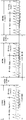
- a specific example of the first measurement frame including the first burst (burst1) and the second burst (burst2) sent by the Nt transmitting antennas may be shown in FIG. 4.
- a triangle represents a chirp signal, and each chirp signal occupies a time slot.
- which transmitting antenna transmits each chirp signal is represented by the number under the chirp signal.
- the first burst includes multiple chirp signals, which are transmitted by Nt transmitting antennas in time sharing; the second burst also includes multiple chirp signals, which are only transmitted by the first transmitting antenna.
- a long bar represents a chirp signal
- the shape of the long bar is only for illustration and does not represent the waveform of the chirp signal in practical applications.
- the specific waveform of the chirp signal is not limited in the embodiment of the present application.
- the order in which the Nt transmit antennas in the first burst transmits chirp signals is not limited.
- the transmission order can be 1, 2, 3...Nt-2, Nt-1, Nt, and the transmission order can also be Those not arranged according to the above-mentioned numbers, such as 5, 8, 7, 10...Nt, Nt-2, Nt-1. That is, in the first burst, the chirp signal can be sent sequentially according to the order of the transmit antennas, or sent out of order.
- Sequential transmission here means that the antenna transmission sequence is consistent with the spatial neighboring relationship of the physical antenna arrangement, and disorder means that the antenna transmission sequence is inconsistent with the spatial neighboring relationship of the antenna physical arrangement.
- the waveform parameters in the first burst can be dynamically configured according to the vehicle environment. Duration, etc. and waveform parameters in the second burst (the number of chirp signals sent by the first transmitting antenna, the duration of each chirp signal, etc.).
- ECUs use common vehicle-mounted buses, such as controller area network (CAN), controller area network with flexible data-rate (CAN-FD), and general ethernet (CAN-FD).
- GE controller area network
- CAN-FD controller area network with flexible data-rate
- CAN-FD general ethernet
- GE vehicle-mounted interfaces configure the waveform parameters of the first burst and the second burst to the radar module.
- the above parameters can be configured to a monolithic microwave integrated circuit (MMIC) through a serial peripheral interface (SPI).
- SPI serial peripheral interface
- flexible configuration can be achieved by configuring the master and slave RF front-end chips.
- the MMIC can be used to enable the transmitter to transmit the aforementioned first measurement frame according to the above configuration.
- the configured parameters are not limited to the above examples, and the configuration parameters are used to instruct the transmitting antenna how to send the chirp signal.
- the configuration parameter may be the number of chirp signals included in the first burst and the second burst, the transmission period of the transmitting antenna, the time period occupied by each transmitting antenna, and the specific value of the duration of each chirp signal , It can also be the equivalent parameters of the number of chirp signals included in the first burst, the transmission period of the transmitting antenna, the time period occupied by each transmitting antenna, and the specific value of the duration of each chirp signal.
- burst is a concept of time period, and burst may also be referred to as a time slot, subframe, frame, and other names.
- a time slot is the smallest unit of time, one burst includes at least one time slot, one subframe includes at least one burst, and one frame includes at least one subframe.
- the target speed range can be achieved by using the echo signal formed after the reflection of the first burst sent in the MIMO mode and the echo signal formed after the reflection of the second burst sent in the SIMO mode after the first burst. Search to match the speed aliasing coefficient of one or more targets, and restore the speed range of the MIMO radar to the SIMO range. At the same time, it can also reduce the complexity of MIMO spectral peak search and reduce the influence of channel phase noise on overlapping arrays.
- sending the SIMO burst (that is, the second burst) after the MIMO burst (that is, the first burst) can make the fast moving target move to the SIMO.
- Ndoppler rounds of chirp signals may be included, and each round includes M chirp signals.
- the sending order, number of signals, duration and other sending parameters of multiple rounds of chirp signals are consistent.
- the number of chirp signals sent by each transmitting antenna may be the same or different.
- Nt transmitting antennas 1, 2, 3...Nt-2, Nt-1, Nt transmit the first burst
- they are transmitted in the order of 1, 2, 3...Nt-2, Nt-1, Nt Ndoppler wheel (exemplarily, N can be 32, 48, 64, 128...)
- N can be 32, 48, 64, 128
- three chirp signals are sent by the transmitting antennas 1, 2, and 3.
- the number of chirp signals sent by the transmitting antennas labeled 1, 2, and 3 is more than the number of chirp signals sent by other transmitting antennas.
- Nt transmitting antennas 1, 2, 3...Nt-2, Nt-1, Nt transmit the first burst
- the second transmitting antenna is still in the first burst.
- a chirp signal is interspersed in a burst.
- the second transmitting antenna intersperses and transmits the chirp signal in the first burst, it may be transmitted periodically or non-periodically.
- the second transmitting antenna and the first transmitting antenna may be the same transmitting antenna or different transmitting antennas. It is not difficult to see that in the first burst, the number of chirp signals sent by the second transmitting antenna is more than the number of chirp signals sent by other transmitting antennas.
- the calculation process is relatively simple when calculating the target speed based on the echo signal reflected in the first measurement frame;
- the number of chirp signals transmitted by each transmitting antenna is different, and the high-density transmitting antenna can be used to further reduce the complexity of spectral peak search.
- the method before the transmitter executes S301 to send the first burst in the first measurement frame, the method further includes: the transmitter sends the third burst in the first measurement frame, and after sending the third burst When transmitting, the number of transmitting antennas used to transmit chirp signals is one, and the transmitting antenna for transmitting the third burst and the transmitting antenna for transmitting the second burst are the same transmitting antenna (that is, the first transmitting antenna);
- the first measurement frame is sent with a duty cycle of P%, P ⁇ 100, the duty cycle is equal to the ratio of the first duration to the second duration, the first duration is the duration of the first measurement frame, and the second duration is sent by the transmitter The time difference between two adjacent measurement frames.
- the third burst is transmitted in the SIMO mode.
- the first burst (burst1) is prefixed with the third burst (burst3), and the first measurement frame shown in FIG. 4 becomes the form shown in FIG. 6. .
- the first burst sent in the middle position is sent in MIMO mode, and its prefix and suffix are sent in SIMO form. Then, in the first measurement frame, one or more When the echo signal formed after the target reflection is processed, two bursts sent in the SIMO mode can be selected for speed matching, which makes the calculation of the target speed easier. In addition, it can also alleviate the problem of the scattering center of fast-moving targets moving with the launch time to a certain extent.
- the transmitter sends the first measurement frame with a P% duty cycle, P ⁇ 100. That is to say, after sending the first measurement frame, there is a certain idle time and processing time, and then the next measurement frame is sent, so there is a duty cycle P%, P ⁇ 100.
- P% duty cycle
- P ⁇ 100 the system power consumption will be relatively large, so in general, P ⁇ 100.
- each measurement frame cannot be greater than 50 ms.
- the transmitter may send three measurement frames as shown in FIG. 7. It can be seen from Figure 7 that after the first measurement frame is sent, there is still processing and idle time. During the processing or idle time, the radar system can process the echo signal of the sent first measurement frame reflected by the target or During the processing or idle time, no processing is performed, only the chirp signal is not sent.
- the transmitter after the transmitter sends the first measurement frame, it further includes: the transmitter sends the fourth burst in the second measurement frame, the second measurement frame is used to measure the speed of the target, and when the fourth burst is sent, multiple Each of the transmitting antennas sends the chirp signal in a time-sharing manner; after the transmitter sends the fourth burst in the second measurement frame, the transmitter sends the fifth burst in the second measurement frame, and then the fifth burst is sent At this time, the number of transmitting antennas used to transmit the chirp signal is one; the transmission parameters of the fifth burst, the second burst and the third burst are the same. Specifically, the transmission parameters include the transmission slope, the transmission antenna, the number of transmitted chirp signals, the duration of each chirp signal, and so on.
- the second burst in the first measurement frame can be regarded as the SIMO prefix in the second measurement frame , So as to achieve the effect of reducing transmission overhead.
- the first measurement frame (Frame0) sent by the transmitter includes Burst3 (equivalent to the third burst), Burst1 (equivalent to the first burst), and Burst2 (equivalent to the second burst). Send) three bursts, among which the sending parameters of Burst3 and Burst2 are the same.
- the second measurement frame (Frame1) can only include Burst1 (equivalent to the fourth burst) and Burst2 (equivalent to the fifth burst); when calculating the speed of the target, the Burst2 in the first measurement frame can be viewed as Is the SIMO prefix in the second measurement frame.
- the third measurement frame (Frame2) also only includes Burst1 and Burst2, and the third measurement frame multiplexes Burst2 in the second measurement frame.
- the second burst in the SIMO mode is used as the suffix after the first burst sent in the MIMO mode, and the echo signal formed after the reflection of the first burst and the second burst
- the echo signal formed after the burst reflection can search the speed range of the target, so as to match the speed aliasing coefficient of one or more targets, and restore the speed measurement range of the MIMO radar to the SIMO speed measurement range.
- the embodiment of the present application also provides a signal processing method for processing the echo signal formed after the transmitted measurement frame is reflected by one or more targets, so as to obtain The speed of one or more targets, and then obtain the azimuth angle of one or more targets (for example, horizontal azimuth angle and vertical azimuth angle).
- the method is applied to MIMO radar.
- the MIMO radar includes a transmitter, a receiver, and a processing unit.
- the transmitter includes multiple transmitting antennas, and the receiver includes multiple receiving antennas.
- the method includes the following steps:
- S901 The receiver receives the first echo signal and the second echo signal.
- the first echo signal is formed by the first burst in the measurement frame sent by the transmitter after being reflected by one or more targets
- the second echo signal is formed by the second burst in the measurement frame through one or more
- the target is formed after reflection, and the second burst is sent after the first burst; when the first burst is sent, each of the multiple transmit antennas sends the chirp signal in time sharing; when the second burst is sent, use
- the number of transmitting antennas for transmitting chirp signals is one.
- the echo signal received by the receiver is the echo signal of the first measurement frame sent by the transmitter in the method shown in FIG. 3 after being reflected by one or more targets.
- the receiver includes Nr receiving antennas, and the Nr receiving antennas receive Nt echo signals according to the transmission sequence of the Nt transmitting antennas, and then according to the Nt transmitting antennas and Nr receiving antennas.
- the positional relationship between the antennas and the transmission sequence of the transmitting antennas convert the received echo signal into a first echo signal and a second echo signal.
- the processing unit determines the speed of one or more targets according to the echo signal received by the receiver.
- the processing unit determines the speed of one or more targets according to the echo signal received by the receiver, which can be implemented in the following manner: the processing unit determines the first identifier according to the first echo signal, and the first identifier is used for Indicate the distance measurement value and speed measurement value of one or more targets; the processing unit determines the second identifier according to the second echo signal, and the second identifier is used to indicate the distance measurement value and speed measurement value of one or more targets; the processing unit The speed of one or more targets is determined according to the first identification and the second identification.
- the first identifier may include a first speed identifier and a first distance identifier
- the second identifier may include a second speed identifier and a second distance identifier.
- the range-Doppler map (RD) can be obtained through operations such as one-dimensional FFT (1D-FFT), two-dimensional FFT (2D-FFT), and coherent/incoherent combining.
- RDMap when detecting according to RDMap, there can be multiple detection methods, including but not limited to ordered statistical-constant false alarm rate (OS-CFAR) detection or unit average-constant false alarm rate Common detection methods such as cell-averaging constant false alarm rate (CA-CFAR) are not particularly limited in the embodiments of this application.
- OS-CFAR ordered statistical-constant false alarm rate
- CA-CFAR cell-averaging constant false alarm rate
- the threshold of CFAR used in the first burst and the second burst may be different.
- a lower threshold is used in the SIMO burst
- a higher threshold is used in the MIMO to ensure that the targets detected in the MIMO burst can find a relatively matching point in the distance among the targets detected in the SIMO burst.
- the first identification and the second identification obtained in the above manner are only used to indicate the possible distance and speed of the target. Among them, there is also a situation where the target speed is aliased. To determine the speed of the target, the first identification and the second identification need to be determined. Further processing.
- the processing unit determines the speed of one or more targets according to the first identifier and the second identifier, which may be implemented in the following manner: the processing unit determines the corresponding speed of the first identifier according to the repetition period transmitted by the first transmitting antenna in the first burst. The aliasing coefficient interval; the processing unit determines the aliasing coefficient subset according to the first identifier, the second identifier, and the aliasing coefficient interval; the processing unit determines the velocity aliasing coefficient according to the aliasing coefficient subset; the processing unit determines the velocity aliasing coefficient according to the velocity aliasing coefficient and the first An indicator determines the speed of one or more targets.
- the first burst includes Ndoppler round chirp signals, and each round includes M chirp signals. Then, if M is an even number, then the aliasing coefficient interval is [-M/2, M/2-1]; if M is an odd number, then the aliasing coefficient interval is [-M-1/2, M-1 /2].
- the speed range of the SIMO burst is M times that of the MIMO burst. Therefore, if there is only one target at the same distance in two bursts, the alias coefficient interval corresponding to MIMO can actually be obtained accurately.
- one element in the aliasing coefficient interval can be matched according to the second speed identifier of the SIMO burst. After multiple targets are matched, the matched elements can be combined. , And only keep the non-repeated part as a subset of aliasing coefficients.
- the RD Map is divided into 512 grids (RD cells) in distance. Take the speed identifier of the corresponding distance unit of the detected target in the SIMO burst and the MIMO burst within a certain threshold.
- the SIMO burst transmission time is 4 times the MIMO burst transmission time
- the speed resolution in the SIMO burst is 4 times the speed resolution of the MIMO burst.
- each grid in the velocity dimension in the SIMO burst is equivalent to 4 grids in the velocity dimension in MIMO.
- the speed resolution in the SIMO burst is dv_MIMO
- the speed resolution in the SIMO burst is 4*dv_MIMO.
- the entire SIMO speed measurement range is divided into 3*Vind_max_MIMO grids, that is, the value range of Vind_SIMO is 0 ⁇ 3*Vind_max_MIMO-1; and the speed resolution in MIMO burst
- the speed rate is dv_MIMO
- the speed measurement range is Vmax_MIMO.
- the entire MIMO speed measurement range is divided into Vind_max_MIMO grids, that is, the value range of Vind_MIMO is 0 ⁇ Vind_max_MIMO-1.
- the second speed identifier obtained in SIMO can be converted to the corresponding MIMO aliasing coefficient interval by the formula Floor(4*Vind_SIMO/Vind_max_MIMO) to obtain an element in the aliasing coefficient interval.
- Floor(4*Vind_SIMO/Vind_max_MIMO) 0, it corresponds to the first element of [-6,-5,-4,-3,-2,-1,0,1,2,3,4,5] , Which is -6.
- the aliasing coefficient subset is a subset of the aliasing coefficient interval.
- the echo signal received by the receiving antenna may be compensated according to (Rind_MIMO, Vind_MIMO) and the order in which the transmitting antenna sends the chirp signal in the first burst.
- the aliasing coefficient of the Vind_SIMO detected in the second burst corresponding to the first burst is calculated.
- G*Nt is a round of chirp signals (Nt is the number of transmitting antennas, and G is the number of chirp signals transmitted by each transmitting antenna in one round.
- the first burst can include multiple rounds of chirp. Signal), a total of N burst1_doppler chirp signals are transmitted in a round of chirp signals (or N burst1_doppler chirp signals are transmitted after zero padding).
- N burst2_doppler chirp signals are transmitted (or N burst2_doppler chirp signals are transmitted after zero padding).
- the repetition period of one transmit antenna in the first burst is Tc_MIMO
- the repetition period of one transmit antenna in the second burst is Tc_SIMO.
- Tc_MIMO G*Nt*Tc_SIMO
- the speed measurement range of the second burst is equivalent to G*Nt times of the first burst.
- Vind_SIMO is equivalent to dividing the G*Nt*Vmax_MIMO interval into N burst2_doppler grids
- Vind_MIMO is equivalent to dividing the Vmax_MIMO interval into N burst1_doppler intervals.
- the corresponding element in the floor (Vind_SIMO/(N burst2_doppler /G*Nt)) and the aforementioned aliasing coefficient interval can be obtained. Therefore, the corresponding element in the aliasing coefficient interval can be solved for each detected Vind_SIMO, and the set of all elements can be unioned and duplicate elements can be deleted as the aliasing coefficient subset S.
- the specific value of the above threshold threshold may be adaptively adjusted according to parameters such as the second speed identifier and the length of the first burst.
- the time interval between the transmission centers of the first burst and the second burst is Tgap
- the Rind_SIMO obtained on the second burst may be within Tgap time due to the existence of the Tgap time difference.
- the Map move K distance grids.
- the threshold can be determined according to the second speed identifier obtained in the second burst and the subset of aliasing coefficients that are less than K distance grids around the unit in the first burst.
- the second method is to solve the aliasing coefficient subset on each distance grid to achieve finer speed matching.
- the calculation complexity of threshold comparison will be introduced in the calculation.
- the method of transmitting chirp signals on two adjacent time slots through two transmitting antennas with overlapping physical positions can be referred to as overlapping.
- the phase difference of the receiving antennas corresponding to two or more adjacent time slots at the time of the overlap is determined only by the Doppler phase caused by the target velocity. Therefore, the corresponding velocity aliasing coefficient can be directly matched through the velocity identification of the target calculated on the two transmitting antennas with overlapping physical positions.
- overlapping arrays may be constructed during the sending process of the first burst and the second burst, so as to achieve the solution of the velocity aliasing coefficient subset.
- velocity aliasing coefficients can calculate the corresponding Doppler phase-compensated received echo data and the original Doppler phase compensation in the aliasing coefficient subsets of the soft overlapping array pairs (adjacent pairs are a pair). Multiply the conjugate of the overlapping sub-signals, sum multiple received signals, and find the alias coefficient corresponding to the minimum value among the multiple alias coefficients included in the alias coefficient subset as the velocity alias coefficient. Or directly calculate the velocity aliasing coefficient according to the phase difference of multiple soft overlapping array pairs.
- the transmitting antenna is used to transmit the measurement frame
- the receiving antenna is used to receive the echo signal formed after the measurement frame is reflected by the target.
- the antenna array can be virtualized into a virtual array including multiple virtual transmitting and receiving channels
- the processing unit converts the received echo signals into the observation result of the virtual array, and can process and calculate according to the observation result of the virtual array to obtain the distance, Speed, azimuth and other information.
- the process of calculating the angle spectrum performs FFT or digital beamforming (DBF) according to the observation result of the virtual array.
- the FFT operation can be accelerated.
- the virtual array is a uniform array or a non-uniform array with a large number of elements
- the virtual MIMO sub-array of the uniform array can be constructed, and the observation result of the virtual MIMO sub-array can be FFT, thereby using For angular spectrum calculation.
- the spacing between each element in the virtual MIMO sub-array is equal, and the number of elements in the virtual MIMO sub-array corresponding to each transmitting antenna is the same.
- the processing unit determines the velocity aliasing coefficient according to the aliasing coefficient subset, including: the processing unit determines the observation result of the virtual MIMO sub-array according to the echo signal received by the receiver; The observation results of the array determine the velocity aliasing coefficient; among them, the virtual MIMO sub-array is a uniform planar sub-array or uniform line sub-array formed by the virtual array elements in the virtual array, and each transmitting antenna corresponds to the virtual array in the virtual MIMO sub-array The number of elements is the same, and the virtual array is formed by multiple transmitting antennas and multiple receiving antennas included in the receiver.
- the positions of the transmitting antennas T1, T2, T3, T4 and the receiving antennas R1, R2, R3, R4 and the virtual array formed can be as shown in FIG. 10, then the virtual array is formed by selecting four elements in the virtual array.
- MIMO sub-array there are two vacancies in the virtual array formed by the transmitting antenna array and the receiving antenna array, and the sub-array is extracted to avoid these two non-uniform arrays
- the observation results of the virtual MIMO sub-array can be calculated by FFT Angle spectrum.
- the positions of the transmitting antenna and the receiving antenna are shown in Fig. 11, and the virtual array formed is shown in Fig. 12. Then, by selecting 16 elements in the virtual array to form a virtual MIMO sub-array, and comparing the virtual MIMO sub-array FFT of the observation result can be used to calculate the angle spectrum.
- the processing unit determines the velocity aliasing coefficient according to the aliasing coefficient subset, including: the processing unit determines the observation result of the virtual MIMO sub-array according to the echo signal received by the receiver; The observation results of the array determine the velocity aliasing coefficient; among them, the virtual MIMO sub-array is a planar sub-array or a linear sub-array formed by the virtual array elements in the virtual array, and the uniform planar sub-array and uniform line sub-array obtained by linear interpolation, Each transmitting antenna corresponds to the same number of virtual array elements in the virtual MIMO sub-array, and the virtual array is formed by multiple transmitting antennas and multiple receiving antennas included in the receiver.
- a virtual MIMO sub-array can be formed by linear interpolation.
- the positions of the transmitting antennas T1, T2, T3, T4 and the receiving antennas R1, R2, R3, R4 and the formed virtual array may be as shown in FIG. 13. It is not difficult to see that the virtual MIMO sub-array that meets the above conditions cannot be found in the virtual array (the R1, 3 and R4, 2 marked by the solid line cannot form a sub-array with R2, 4, R3, 1), and it can be found by interpolation Corresponding array elements, thereby forming a virtual MIMO sub-array, and then calculating the angle spectrum. Among them, the observation result of the interpolation point can be obtained by averaging.
- the processing unit can determine the velocity of one or more targets according to the velocity aliasing coefficient and the first identifier. For a specific manner, refer to the description in the prior art, which will not be repeated here.
- the method shown in FIG. 9 may further include: the receiver receives a third echo signal, the third echo signal is formed by the third burst in the measurement frame after being reflected by one or more targets, and the third burst Sent before the first burst. Then, the processing unit determines the speed of one or more targets according to the echo signals received by the receiver, which can be specifically implemented in the following manner: if one or more targets move away from the radar system, the processing unit according to the first return The wave signal and the third echo signal determine the speed of one or more targets; if one or more targets move toward the direction of the radar system, the processing unit determines one or more targets according to the first echo signal and the second echo signal. The speed of each target.
- the prefix (third burst) is used for the target in the far direction for matching
- the suffix (the second burst) is used for the target in the close direction for matching.
- the target Since the target will actually move on three bursts. For distant targets, this movement will affect the signal strength of the received target. When the target is far away, the distance between the target and the second burst is getting farther and farther, so that the signal strength of the target is reduced, so the data in the third burst is more reliable. When the target is close, the distance between the target and the second burst is getting closer, so that the target signal strength increases, and the data in the second burst is more reliable.
- the specific manner of determining the speed of one or more targets according to the first echo signal and the third echo signal can be achieved by determining the speed of one or more targets according to the first echo signal and the second echo signal. Ways, I won’t repeat them here.
- the processing unit can also determine the target point where the measured data in the two bursts sent in the SIMO mode, the second burst and the third burst, are consistent. Perform clustering and tracking.
- SIMO burst and MIMO burst are mainly inconsistent in judgment at higher speed points. This is caused by the micro-Doppler and multipath of the target.
- the local micro-Doppler characteristics of the target cause the target's macro-velocity and micro-velocity to be inconsistent.
- the speed of the wheel and the speed of the car body are different, and the speed of the human arm and the human torso are different; in multipath reflection, the measured target distance And the speed is greater than the real goal.
- the speed results of SIMO burst and MIMO burst have a large deviation. Therefore, consistent target points can be used for clustering and tracking, so as to obtain the correct macro-velocity of the target and predict the motion state of the target based on the macro-velocity.
- the echo signal formed after the reflection of the first burst sent in the MIMO mode and the second burst sent after the first burst in the SIMO mode are reflected.
- the echo signal of the MIMO radar is used to search the speed range of the target, so as to match the speed aliasing coefficient of one or more targets, and restore the speed measurement range of the MIMO radar to the SIMO speed measurement range.
- An embodiment of the present application provides a signal transmission device, which can be used to execute the signal transmission method shown in FIG. 3.
- the signal transmission device includes a transmitter 1401.
- the transmitter 1401 which includes multiple transmitting antennas, is used to transmit the first burst in the first measurement frame, and the first measurement frame is used to measure the speed of the target.
- the multiple transmitting antennas Each transmitting antenna in the transmitting antenna transmits the chirp signal in time sharing; and, after transmitting the first burst in the first measurement frame, transmitting the second burst in the first measurement frame, and when transmitting the second burst, The number of transmitting antennas used to transmit chirp signals is one.
- the transmitter 1401 is further configured to: before sending the first burst in the first measurement frame, send the third burst in the first measurement frame; when sending the third burst, send the chirp signal
- the number of transmitting antennas is one, and the transmitting antenna for transmitting the third burst and the transmitting antenna for transmitting the second burst are the same transmitting antenna; wherein, the transmitter 1401 transmits the first measurement frame with a P% duty cycle, P ⁇ 100, the duty cycle is equal to the ratio of the first duration to the second duration, the first duration is the duration of the first measurement frame, and the second duration is the time difference between two adjacent measurement frames sent by the transmitter 1401.
- the transmitter 1401 is further configured to: after sending the first measurement frame, send the fourth burst in the second measurement frame, the second measurement frame is used to measure the speed of the target, and when the fourth burst is sent, Each of the multiple transmitting antennas transmits the chirp signal in time sharing; after transmitting the fourth burst in the second measurement frame, the fifth burst in the second measurement frame is transmitted, and when the fifth burst is transmitted, The number of transmitting antennas used to transmit the chirp signal is one; the transmission parameters of the fifth burst, the second burst, and the third burst are the same.
- the transmission parameter includes one or more of the following: a transmission slope, a transmission antenna, the number of transmitted chirp signals, or the duration of each chirp signal.
- the first measurement frame is any one of FMCW, MFSK or PMCW.
- the number of chirp signals transmitted by each of the multiple transmitting antennas is different.
- the signal transmission device 1400 further includes: a processing unit 1402, configured to determine the configuration of the first measurement frame, and send the configuration of the first measurement frame to the monolithic microwave integrated circuit MMIC through the interface, and the MMIC is used to The configuration of a measurement frame enables the transmitter to send the first measurement frame.
- a processing unit 1402 configured to determine the configuration of the first measurement frame, and send the configuration of the first measurement frame to the monolithic microwave integrated circuit MMIC through the interface, and the MMIC is used to The configuration of a measurement frame enables the transmitter to send the first measurement frame.
- the signal transmission device 1400 shown in FIG. 14 can be used to implement the signal transmission method shown in FIG. 3, and the implementation of the signal transmission device 1400 that is not described in detail can be referred to the relevant information in the signal transmission method shown in FIG. description.
- the embodiment of the present application provides a signal processing device, which can be used to execute the signal processing method shown in FIG. 9.
- the signal transmission device 1500 includes a receiver 1501 and a processing unit 1502.
- the receiver 1501 is used to receive the first echo signal and the second echo signal.
- the first echo signal is formed by the first burst in the measurement frame sent by the transmitter after being reflected by one or more targets, and the second echo signal
- the wave signal is formed by the second burst in the measurement frame being reflected by one or more targets.
- the second burst is sent after the first burst; when the first burst is sent, each of the multiple transmitting antennas
- the transmitting antenna transmits the chirp signal in time sharing; when transmitting the second burst, the number of transmitting antennas used to transmit the chirp signal is one.
- the processing unit 1502 is configured to determine the speed of one or more targets according to the echo signal received by the receiver 1501.
- the processing unit 1502 determines the speed of one or more targets according to the echo signal received by the receiver 1501, it is specifically used to: determine a first identifier according to the first echo signal, and the first identifier is used to indicate one The distance measurement value and speed measurement value of one or more targets; the second identifier is determined according to the second echo signal, and the second identifier is used to indicate the distance measurement value and speed measurement value of one or more targets; The second identification determines the speed of one or more targets.
- the processing unit 1502 determines the speed of one or more targets according to the first identifier and the second identifier, it is specifically configured to: determine the corresponding to the first identifier according to the repetition period transmitted by the first transmitting antenna in the first burst.
- the aliasing coefficient interval; the aliasing coefficient subset is determined according to the first identification, the second identification and the aliasing coefficient interval; the velocity aliasing coefficient is determined according to the aliasing coefficient subset; one or more is determined according to the velocity aliasing coefficient and the first identification The speed of each target.
- the receiver 1501 is further configured to: receive a third echo signal, the third echo signal is formed by the third burst in the measurement frame after being reflected by one or more targets, and the third burst is in the Send before the first burst; when the processing unit 1502 determines the speed of one or more targets according to the echo signal received by the receiver 1501, it is specifically used for: if one or more targets move away from the radar system, Determine the speed of one or more targets according to the first echo signal and the third echo signal; if one or more targets move toward the radar system, determine the speed according to the first echo signal and the second echo signal The speed of one or more targets.
- the processing unit 1502 is specifically configured to: determine the observation result of the virtual MIMO sub-array according to the echo signal received by the receiver 1501; Observation results determine the velocity aliasing coefficient; among them, the virtual MIMO sub-array is a uniform planar sub-array or a uniform linear sub-array formed by the virtual elements in the virtual array, and each transmitting antenna corresponds to the number of virtual elements in the virtual MIMO sub-array Similarly, the virtual array is formed by multiple transmitting antennas and multiple receiving antennas included in the receiver 1501.
- the processing unit 1502 is specifically configured to: determine the observation result of the virtual MIMO sub-array according to the echo signal received by the receiver 1501; Observation results determine the velocity aliasing coefficient; among them, the virtual MIMO sub-array is a planar sub-array or a linear sub-array formed by the virtual array elements in the virtual array, and the uniform planar sub-array and uniform linear sub-array obtained by linear interpolation, each The transmitting antennas correspond to the same number of virtual array elements in the virtual MIMO sub-array, and the virtual array is formed by multiple transmitting antennas and multiple receiving antennas included in the receiver 1501.
- the signal processing device 1500 shown in FIG. 15 can be used to execute the signal processing method shown in FIG. 9, and the implementation manners that are not described in detail in the signal processing device 1500 can be referred to in the signal processing method shown in FIG. 3 description.
- the embodiments of the present application also provide a radar system.
- the radar system 1600 includes a transmitter 1601, a receiver 1602, and a processing unit 1603.
- the transmitter 1601 includes multiple transmitting antennas for transmitting the first burst in the measurement frame.
- the measurement frame is used to measure the speed of the target.
- each of the multiple transmitting antennas Two transmitting antennas transmit the chirp signal in time sharing; and, after transmitting the first burst in the measurement frame, transmit the second burst in the measurement frame, and when transmitting the second burst, it is used to transmit the chirp signal
- the number of transmitting antennas is one.
- the receiver 1602 is used to receive the first echo signal and the second echo signal; the first echo signal is formed by the first burst after being reflected by one or more targets, and the second echo signal is formed by the second burst One or more targets are formed after reflection.
- the processing unit 1603 is configured to determine the speed of one or more targets according to the echo signal received by the receiver 1602.
Landscapes
- Engineering & Computer Science (AREA)
- Radar, Positioning & Navigation (AREA)
- Remote Sensing (AREA)
- Computer Networks & Wireless Communication (AREA)
- Physics & Mathematics (AREA)
- General Physics & Mathematics (AREA)
- Electromagnetism (AREA)
- Signal Processing (AREA)
- Radar Systems Or Details Thereof (AREA)
Abstract
L'invention concerne un procédé et un dispositif d'émission de signal, un procédé et un dispositif de traitement de signal, et un système radar, capables d'activer un radar entrée multiple sortie multiple (MIMO) pour restaurer avec précision la vitesse d'une cible vers une plage de mesure de vitesse d'un radar SIMO, le procédé d'émission de signal étant appliqué au radar MIMO. Le radar MIMO comprend un émetteur comprenant une pluralité d'antennes d'émission. Le procédé d'émission de signal comprend les étapes suivantes : un émetteur envoie une première rafale dans une première trame de mesure, la première trame de mesure étant utilisée pour mesurer la vitesse d'une cible, pendant l'envoi de la première rafale, chacune de la pluralité d'antennes d'émission envoyant un signal chirp d'une manière en temps partagé ; et après l'envoi de la première rafale par l'émetteur dans la première trame de mesure, l'émetteur envoie une seconde rafale dans la première trame de mesure, lorsque la seconde rafale est envoyée, une antenne d'émission est utilisée pour envoyer le signal chirp.
Priority Applications (6)
| Application Number | Priority Date | Filing Date | Title |
|---|---|---|---|
| JP2022511088A JP2022545001A (ja) | 2019-08-19 | 2019-08-19 | 信号送信方法および装置、信号処理方法および装置、ならびにレーダシステム |
| CN201980059686.2A CN112689964B (zh) | 2019-08-19 | 2019-08-19 | 信号传输方法及装置、信号处理方法及装置以及雷达系统 |
| PCT/CN2019/101409 WO2021031077A1 (fr) | 2019-08-19 | 2019-08-19 | Procédé et dispositif d'émission de signal, procédé et dispositif de traitement de signal, et système radar |
| CN202210524903.4A CN115079095A (zh) | 2019-08-19 | 2019-08-19 | 信号传输方法及装置、信号处理方法及装置以及雷达系统 |
| EP19942231.2A EP4016884A4 (fr) | 2019-08-19 | 2019-08-19 | Procédé et dispositif d'émission de signal, procédé et dispositif de traitement de signal, et système radar |
| US17/675,258 US20220171021A1 (en) | 2019-08-19 | 2022-02-18 | Signal Transmission Method and Apparatus, Signal Processing Method and Apparatus, and Radar System |
Applications Claiming Priority (1)
| Application Number | Priority Date | Filing Date | Title |
|---|---|---|---|
| PCT/CN2019/101409 WO2021031077A1 (fr) | 2019-08-19 | 2019-08-19 | Procédé et dispositif d'émission de signal, procédé et dispositif de traitement de signal, et système radar |
Related Child Applications (1)
| Application Number | Title | Priority Date | Filing Date |
|---|---|---|---|
| US17/675,258 Continuation US20220171021A1 (en) | 2019-08-19 | 2022-02-18 | Signal Transmission Method and Apparatus, Signal Processing Method and Apparatus, and Radar System |
Publications (1)
| Publication Number | Publication Date |
|---|---|
| WO2021031077A1 true WO2021031077A1 (fr) | 2021-02-25 |
Family
ID=74659753
Family Applications (1)
| Application Number | Title | Priority Date | Filing Date |
|---|---|---|---|
| PCT/CN2019/101409 WO2021031077A1 (fr) | 2019-08-19 | 2019-08-19 | Procédé et dispositif d'émission de signal, procédé et dispositif de traitement de signal, et système radar |
Country Status (5)
| Country | Link |
|---|---|
| US (1) | US20220171021A1 (fr) |
| EP (1) | EP4016884A4 (fr) |
| JP (1) | JP2022545001A (fr) |
| CN (2) | CN112689964B (fr) |
| WO (1) | WO2021031077A1 (fr) |
Cited By (1)
| Publication number | Priority date | Publication date | Assignee | Title |
|---|---|---|---|---|
| CN113949610A (zh) * | 2021-09-30 | 2022-01-18 | 加特兰微电子科技(上海)有限公司 | 波形控制方法、无线电器件、无线电信号及其发射链路 |
Families Citing this family (2)
| Publication number | Priority date | Publication date | Assignee | Title |
|---|---|---|---|---|
| US11693107B2 (en) * | 2020-09-29 | 2023-07-04 | Steradian Semiconductors Private Limited | System, device and method for efficient MIMO radar |
| WO2023087232A1 (fr) * | 2021-11-19 | 2023-05-25 | 华为技术有限公司 | Système radar et procédé de détection de piéton, et véhicule |
Citations (6)
| Publication number | Priority date | Publication date | Assignee | Title |
|---|---|---|---|---|
| CN102783038A (zh) * | 2010-02-26 | 2012-11-14 | 索尼公司 | 提供递增冗余的编码器和编码方法 |
| CN105722234A (zh) * | 2016-02-05 | 2016-06-29 | 北京佰才邦技术有限公司 | 在非授权频段中调度资源的方法、基站和终端 |
| US9759810B1 (en) * | 2017-02-03 | 2017-09-12 | Scidea Research, Inc. | Hybrid pulse compression waveform for high resolution imaging |
| CN107925446A (zh) * | 2015-05-11 | 2018-04-17 | 凝聚技术股份有限公司 | 正交时间频率空间调制系统 |
| CN107925434A (zh) * | 2015-05-11 | 2018-04-17 | 凝聚技术公司 | 用于数据的辛正交时频移位调制和传输的系统和方法 |
| CN107979402A (zh) * | 2016-10-25 | 2018-05-01 | 华为技术有限公司 | 一种信道状态信息测量方法及装置 |
Family Cites Families (12)
| Publication number | Priority date | Publication date | Assignee | Title |
|---|---|---|---|---|
| JP4032881B2 (ja) * | 2002-08-28 | 2008-01-16 | 株式会社豊田中央研究所 | Fm−cwレーダ装置 |
| US9288026B2 (en) * | 2009-06-22 | 2016-03-15 | Qualcomm Incorporated | Transmission of reference signal on non-contiguous clusters of resources |
| JP5627780B2 (ja) * | 2011-06-24 | 2014-11-19 | パナソニック インテレクチュアル プロパティ コーポレーション オブアメリカPanasonic Intellectual Property Corporation of America | 送信装置、送信方法、受信装置および受信方法 |
| DE102014212284A1 (de) * | 2014-06-26 | 2015-12-31 | Robert Bosch Gmbh | MIMO-Radarmessverfahren |
| US9541638B2 (en) * | 2014-11-11 | 2017-01-10 | Nxp B.V. | MIMO radar system |
| US9326295B1 (en) * | 2014-12-10 | 2016-04-26 | Sony Corporation | Method and apparatus for transmitting a-priori information in a communication system |
| US11002829B2 (en) * | 2016-04-15 | 2021-05-11 | Mediatek Inc. | Radar interference mitigation method and apparatus |
| DE102016207871A1 (de) * | 2016-05-09 | 2017-11-09 | Robert Bosch Gmbh | Azimutbestimmung mittels eines Radarsensors |
| DE102016221947A1 (de) * | 2016-11-09 | 2018-05-09 | Robert Bosch Gmbh | Radarsensor für Kraftfahrzeuge |
| EP3425419B1 (fr) * | 2017-07-05 | 2024-01-03 | Stichting IMEC Nederland | Procédé et système de localisation et de surveillance des êtres vivantes |
| JP7057096B2 (ja) * | 2017-10-16 | 2022-04-19 | 株式会社デンソーテン | レーダ装置及びレーダ装置の送信処理方法 |
| GB201806593D0 (en) * | 2018-04-23 | 2018-06-06 | Trw Ltd | Improvements relating to radar apparatus |
-
2019
- 2019-08-19 EP EP19942231.2A patent/EP4016884A4/fr active Pending
- 2019-08-19 CN CN201980059686.2A patent/CN112689964B/zh active Active
- 2019-08-19 WO PCT/CN2019/101409 patent/WO2021031077A1/fr unknown
- 2019-08-19 CN CN202210524903.4A patent/CN115079095A/zh active Pending
- 2019-08-19 JP JP2022511088A patent/JP2022545001A/ja active Pending
-
2022
- 2022-02-18 US US17/675,258 patent/US20220171021A1/en active Pending
Patent Citations (6)
| Publication number | Priority date | Publication date | Assignee | Title |
|---|---|---|---|---|
| CN102783038A (zh) * | 2010-02-26 | 2012-11-14 | 索尼公司 | 提供递增冗余的编码器和编码方法 |
| CN107925446A (zh) * | 2015-05-11 | 2018-04-17 | 凝聚技术股份有限公司 | 正交时间频率空间调制系统 |
| CN107925434A (zh) * | 2015-05-11 | 2018-04-17 | 凝聚技术公司 | 用于数据的辛正交时频移位调制和传输的系统和方法 |
| CN105722234A (zh) * | 2016-02-05 | 2016-06-29 | 北京佰才邦技术有限公司 | 在非授权频段中调度资源的方法、基站和终端 |
| CN107979402A (zh) * | 2016-10-25 | 2018-05-01 | 华为技术有限公司 | 一种信道状态信息测量方法及装置 |
| US9759810B1 (en) * | 2017-02-03 | 2017-09-12 | Scidea Research, Inc. | Hybrid pulse compression waveform for high resolution imaging |
Non-Patent Citations (1)
| Title |
|---|
| See also references of EP4016884A4 * |
Cited By (1)
| Publication number | Priority date | Publication date | Assignee | Title |
|---|---|---|---|---|
| CN113949610A (zh) * | 2021-09-30 | 2022-01-18 | 加特兰微电子科技(上海)有限公司 | 波形控制方法、无线电器件、无线电信号及其发射链路 |
Also Published As
| Publication number | Publication date |
|---|---|
| CN112689964B (zh) | 2022-05-13 |
| EP4016884A1 (fr) | 2022-06-22 |
| JP2022545001A (ja) | 2022-10-24 |
| CN112689964A (zh) | 2021-04-20 |
| CN115079095A (zh) | 2022-09-20 |
| EP4016884A4 (fr) | 2022-08-24 |
| US20220171021A1 (en) | 2022-06-02 |
Similar Documents
| Publication | Publication Date | Title |
|---|---|---|
| CN113287036B (zh) | 一种速度解模糊的方法及回波信号处理装置 | |
| US20220171021A1 (en) | Signal Transmission Method and Apparatus, Signal Processing Method and Apparatus, and Radar System | |
| WO2020118582A1 (fr) | Procédé de traitement de signal, système radar et véhicule | |
| US20220171050A1 (en) | Signal transmission method and apparatus, signal processing method and apparatus, and radar system | |
| WO2021243491A1 (fr) | Procédé et dispositif d'émission et de réception de signal radar | |
| WO2022020995A1 (fr) | Procédé et dispositif de traitement de signal et support de stockage | |
| WO2021189268A1 (fr) | Procédé d'émission et de réception de signal radar, et radar | |
| CN112673271B (zh) | 一种近场估计的方法及装置 | |
| WO2021258292A1 (fr) | Procédé et dispositif de traitement de signal, dispositif radar et support de stockage | |
| CN115087881B (zh) | 一种波达角aoa估计方法和装置 | |
| CN112654889B (zh) | 拍频信号处理方法及装置 |
Legal Events
| Date | Code | Title | Description |
|---|---|---|---|
| 121 | Ep: the epo has been informed by wipo that ep was designated in this application |
Ref document number: 19942231 Country of ref document: EP Kind code of ref document: A1 |
|
| ENP | Entry into the national phase |
Ref document number: 2022511088 Country of ref document: JP Kind code of ref document: A |
|
| NENP | Non-entry into the national phase |
Ref country code: DE |
|
| ENP | Entry into the national phase |
Ref document number: 2019942231 Country of ref document: EP Effective date: 20220321 |