WO2021029292A1 - 画像診断支援装置、内視鏡システム、画像診断支援方法、及び画像診断支援プログラム - Google Patents
画像診断支援装置、内視鏡システム、画像診断支援方法、及び画像診断支援プログラム Download PDFInfo
- Publication number
- WO2021029292A1 WO2021029292A1 PCT/JP2020/029967 JP2020029967W WO2021029292A1 WO 2021029292 A1 WO2021029292 A1 WO 2021029292A1 JP 2020029967 W JP2020029967 W JP 2020029967W WO 2021029292 A1 WO2021029292 A1 WO 2021029292A1
- Authority
- WO
- WIPO (PCT)
- Prior art keywords
- notification
- mode
- unit
- voice
- image
- Prior art date
- Legal status (The legal status is an assumption and is not a legal conclusion. Google has not performed a legal analysis and makes no representation as to the accuracy of the status listed.)
- Ceased
Links
Images






Classifications
-
- A—HUMAN NECESSITIES
- A61—MEDICAL OR VETERINARY SCIENCE; HYGIENE
- A61B—DIAGNOSIS; SURGERY; IDENTIFICATION
- A61B1/00—Instruments for performing medical examinations of the interior of cavities or tubes of the body by visual or photographical inspection, e.g. endoscopes; Illuminating arrangements therefor
- A61B1/00002—Operational features of endoscopes
- A61B1/00043—Operational features of endoscopes provided with output arrangements
-
- A—HUMAN NECESSITIES
- A61—MEDICAL OR VETERINARY SCIENCE; HYGIENE
- A61B—DIAGNOSIS; SURGERY; IDENTIFICATION
- A61B1/00—Instruments for performing medical examinations of the interior of cavities or tubes of the body by visual or photographical inspection, e.g. endoscopes; Illuminating arrangements therefor
- A61B1/06—Instruments for performing medical examinations of the interior of cavities or tubes of the body by visual or photographical inspection, e.g. endoscopes; Illuminating arrangements therefor with illuminating arrangements
- A61B1/0638—Instruments for performing medical examinations of the interior of cavities or tubes of the body by visual or photographical inspection, e.g. endoscopes; Illuminating arrangements therefor with illuminating arrangements providing two or more wavelengths
-
- A—HUMAN NECESSITIES
- A61—MEDICAL OR VETERINARY SCIENCE; HYGIENE
- A61B—DIAGNOSIS; SURGERY; IDENTIFICATION
- A61B1/00—Instruments for performing medical examinations of the interior of cavities or tubes of the body by visual or photographical inspection, e.g. endoscopes; Illuminating arrangements therefor
- A61B1/00002—Operational features of endoscopes
- A61B1/00004—Operational features of endoscopes characterised by electronic signal processing
- A61B1/00009—Operational features of endoscopes characterised by electronic signal processing of image signals during a use of endoscope
- A61B1/000094—Operational features of endoscopes characterised by electronic signal processing of image signals during a use of endoscope extracting biological structures
-
- A—HUMAN NECESSITIES
- A61—MEDICAL OR VETERINARY SCIENCE; HYGIENE
- A61B—DIAGNOSIS; SURGERY; IDENTIFICATION
- A61B1/00—Instruments for performing medical examinations of the interior of cavities or tubes of the body by visual or photographical inspection, e.g. endoscopes; Illuminating arrangements therefor
- A61B1/00002—Operational features of endoscopes
- A61B1/00011—Operational features of endoscopes characterised by signal transmission
- A61B1/00013—Operational features of endoscopes characterised by signal transmission using optical means
-
- A—HUMAN NECESSITIES
- A61—MEDICAL OR VETERINARY SCIENCE; HYGIENE
- A61B—DIAGNOSIS; SURGERY; IDENTIFICATION
- A61B1/00—Instruments for performing medical examinations of the interior of cavities or tubes of the body by visual or photographical inspection, e.g. endoscopes; Illuminating arrangements therefor
- A61B1/00002—Operational features of endoscopes
- A61B1/00043—Operational features of endoscopes provided with output arrangements
- A61B1/00045—Display arrangement
- A61B1/0005—Display arrangement combining images e.g. side-by-side, superimposed or tiled
-
- A—HUMAN NECESSITIES
- A61—MEDICAL OR VETERINARY SCIENCE; HYGIENE
- A61B—DIAGNOSIS; SURGERY; IDENTIFICATION
- A61B1/00—Instruments for performing medical examinations of the interior of cavities or tubes of the body by visual or photographical inspection, e.g. endoscopes; Illuminating arrangements therefor
- A61B1/04—Instruments for performing medical examinations of the interior of cavities or tubes of the body by visual or photographical inspection, e.g. endoscopes; Illuminating arrangements therefor combined with photographic or television appliances
- A61B1/045—Control thereof
-
- G—PHYSICS
- G16—INFORMATION AND COMMUNICATION TECHNOLOGY [ICT] SPECIALLY ADAPTED FOR SPECIFIC APPLICATION FIELDS
- G16H—HEALTHCARE INFORMATICS, i.e. INFORMATION AND COMMUNICATION TECHNOLOGY [ICT] SPECIALLY ADAPTED FOR THE HANDLING OR PROCESSING OF MEDICAL OR HEALTHCARE DATA
- G16H30/00—ICT specially adapted for the handling or processing of medical images
- G16H30/40—ICT specially adapted for the handling or processing of medical images for processing medical images, e.g. editing
-
- G—PHYSICS
- G16—INFORMATION AND COMMUNICATION TECHNOLOGY [ICT] SPECIALLY ADAPTED FOR SPECIFIC APPLICATION FIELDS
- G16H—HEALTHCARE INFORMATICS, i.e. INFORMATION AND COMMUNICATION TECHNOLOGY [ICT] SPECIALLY ADAPTED FOR THE HANDLING OR PROCESSING OF MEDICAL OR HEALTHCARE DATA
- G16H50/00—ICT specially adapted for medical diagnosis, medical simulation or medical data mining; ICT specially adapted for detecting, monitoring or modelling epidemics or pandemics
- G16H50/20—ICT specially adapted for medical diagnosis, medical simulation or medical data mining; ICT specially adapted for detecting, monitoring or modelling epidemics or pandemics for computer-aided diagnosis, e.g. based on medical expert systems
Definitions
- the present invention relates to an image diagnosis support device for notifying a recognition result of a medical image, an endoscope system, an image diagnosis support method, and an image diagnosis support program.
- Patent Document 1 describes a capsule endoscope that outputs a notification sound (notice sound, notification sound, end sound) notifying that a feature image is displayed.
- the timing when notification is required is about a few seconds after the area of interest is detected, and once the operator discovers the area of interest and starts detailed observation, the notification rather hinders the observation. It may discourage the surgeon's willingness to perform the procedure or delay the discovery of new areas of interest.
- voice notification has high notification power, but on the other hand, it may interfere with the voice of other devices such as a heart rate monitor, and special measures are required.
- the present invention has been made in view of such circumstances, and provides an image diagnosis support device, an endoscope system, an image diagnosis support method, and an image diagnosis support program capable of appropriately performing screen display and voice notification.
- the purpose is to do.
- the image diagnosis support device includes an image acquisition unit that acquires a time-series medical image, a recognition unit that recognizes a region of interest in the acquired medical image, and a recognition unit. It is provided with a notification unit that notifies the recognition result by screen display and voice, and a judgment unit that determines the inspection status.
- the notification unit performs notification by screen display regardless of the judgment result, and the judgment result is obtained.
- the voice notification is performed by either the first mode using the voice having the first notification power and the second mode using the voice having the second notification power lower than the first notification power. ..
- the notification unit performs notification by screen display regardless of the result of the determination, and according to the result of the determination, the first mode using the voice having the first notification power and the first notification power
- the voice notification is performed by either the second mode using the voice having the lower second notification power.
- the "region of interest” may include a lesion region, a lesion candidate region, and a region after treatment
- "recognition" of the region of interest refers to the presence, number, position, size, shape, and It may include determining the type, movement in the image, degree of lesion, etc. (detection, measurement, classification, etc.).
- acquisition of medical image includes sequentially acquiring a plurality of medical images taken at a predetermined frame rate. The acquisition may or may not be real-time.
- the image acquisition unit may acquire a plurality of medical images by photographing an image with an imaging device including an imaging optical system and an image sensor, or acquire a plurality of pre-recorded medical images via a network and / or a recording medium. You may.
- the diagnostic imaging support device is the first or second aspect, and the notification unit is in the state of magnifying the medical image, observing the dye, observing the special light, treating, or cleaning the result of the determination. If any one or more of them are used, the notification in the second mode is performed.
- the notification unit is in the state of magnifying the medical image, observing the dye, observing the special light, treating, or cleaning the result of the determination. If any one or more of them are used, the notification in the second mode is performed.
- the notification when the medical image is being enlarged and displayed, it is considered that the user is aware of the area of interest, and the notification is performed in the second mode with low notification power.
- the recognition unit recognizes the feature of the region of interest, and the determination unit determines whether or not the feature satisfies the criterion.
- the notification unit performs notification in the second mode.
- “features” and “criteria” may be set according to the user's settings.
- the diagnostic imaging support device recognizes at least one of the size, position, shape, number, and disease type of the region of interest as a feature of the recognition unit, and the notification unit recognizes it.
- the notification in the second mode is performed.
- the fifth aspect specifically defines the "feature" of the region of interest, and the "reference" for the feature can be set for each of the size, position, shape, number, and disease type.
- the size is equal to or larger than the determined area
- the position is a specific position (for example, near the center) of the medical image
- the shape of the region of interest is a specific shape
- the number of regions of interest is a determined number.
- the diagnostic imaging support device is in any one of the first to fifth aspects, in which the notification unit lowers the volume of the voice in the second mode than in the first mode, as compared with the first mode. Notification is performed by at least one of lowering the pitch of the voice (lowering the sound), slowing the pitch of the voice compared to the first mode, and stopping the notification by voice.
- the sixth aspect defines a specific method for lowering the notification power.
- the endoscope system according to the seventh aspect of the present invention includes an image diagnosis support device according to any one of the first to sixth aspects and a display device for displaying a medical image. And an endoscopic scope that is inserted into a subject and has an imaging unit that captures a medical image. Since the endoscope system according to the seventh aspect includes the image diagnosis support device according to any one of the first to sixth aspects, screen display and voice notification can be appropriately performed.
- the image diagnosis support method includes an image acquisition step of acquiring a time-series medical image, a recognition step of recognizing a region of interest in the acquired medical image, and a recognition step. It has a notification process for notifying the recognition result by screen display and voice, and a determination process for determining the inspection status.
- notification is performed by screen display regardless of the determination result, and the determination result is obtained.
- voice notification is performed by either a first mode using a voice having a first notification power or a second mode using a voice having a second notification power lower than the first notification power.
- screen display and voice notification can be appropriately performed as in the first aspect.
- diagnostic imaging support method according to the eighth aspect may further include the same configurations as those of the second to sixth aspects.
- the image diagnosis support program has an image acquisition function for acquiring a time-series medical image and a recognition for recognizing a region of interest in the acquired medical image. It is an image diagnosis support program that executes a function, a notification function that notifies the recognition result by screen display and voice, and a judgment function that judges the inspection status, and the notification function does not depend on the judgment result.
- a first mode in which notification is performed by screen display and a voice having a first notification power is used according to the result of determination, and a second mode in which a voice having a second notification power lower than the first notification power is used.
- the notification by voice is performed by either.
- screen display and voice notification can be appropriately performed as in the first and eighth aspects.
- the diagnostic imaging support program according to the ninth aspect may further include the same configurations (functions) as those of the second to sixth aspects.
- a non-temporary recording medium on which a computer-readable code of the diagnostic imaging support program of these aspects is recorded can also be mentioned as an aspect of the present invention.
- the image diagnosis support device As described above, according to the image diagnosis support device, the endoscope system, the image diagnosis support method, and the image diagnosis support program according to the present invention, screen display and voice notification can be appropriately performed.
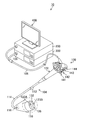
- FIG. 1 is a diagram showing a configuration of an endoscope system according to a first embodiment.
- FIG. 2 is another diagram showing the configuration of the endoscopic system.
- FIG. 3 is a functional block diagram of the image processing unit.
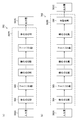
- FIG. 4 is a diagram showing a configuration example of a convolutional neural network.
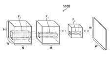
- FIG. 5 is a diagram showing a state of the convolution process by the filter.
- FIG. 6 is a diagram showing information recorded in the recording unit.
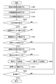
- FIG. 7 is a flowchart showing the procedure of the medical image processing method according to the first embodiment.
- FIG. 8 is a diagram showing an example of a setting screen of a notification mode by screen display.
- FIG. 9 is a diagram showing an example of a setting screen of a voice notification mode.
- FIG. 1 is an external view of the endoscope system 10 (imaging diagnosis support device, medical image processing device, endoscope system), and FIG. 2 is a block diagram showing a main configuration of the endoscope system 10.
- the endoscope system 10 includes an endoscope scope 100 (medical device, endoscope scope, endoscope main body), processor 200 (imaging diagnosis support device, medical image processing device), and the like. It is composed of a light source device 300 (light source device) and a monitor 400 (display device).
- the endoscope scope 100 includes a hand operation unit 102 and an insertion unit 104 connected to the hand operation unit 102.
- the operator grasps and operates the hand operation unit 102, inserts the insertion unit 104 into the body of the subject (living body), and observes it.
- the hand operation unit 102 is provided with an air supply / water supply button 141, a suction button 142, a function button 143 to which various functions are assigned, and a shooting button 144 for receiving a shooting instruction operation (still image, moving image). ..
- the insertion portion 104 is composed of a soft portion 112, a curved portion 114, and a tip hard portion 116 in this order from the hand operation portion 102 side.
- the curved portion 114 is connected to the base end side of the hard tip portion 116, and the soft portion 112 is connected to the base end side of the curved portion 114.
- the hand operation unit 102 is connected to the base end side of the insertion unit 104. The user can bend the curved portion 114 and change the direction of the hard tip portion 116 up, down, left and right by operating the hand operating portion 102.
- the tip rigid portion 116 is provided with a photographing optical system 130, an illumination portion 123, a forceps opening 126, and the like (see FIGS. 1 and 2).
- white light and / or narrow band light (red narrow band light, green narrow band light, etc.) are transmitted from the illumination lenses 123A and 123B of the illumination unit 123.
- narrow band light red narrow band light, green narrow band light, etc.
- One or more of blue narrow band light and purple narrow band light can be irradiated.
- cleaning water is discharged from a water supply nozzle (not shown) to clean the photographing lens 132 (photographing lens, photographing unit) of the photographing optical system 130 and the illumination lenses 123A and 123B. Can be done.
- a pipe line (not shown) communicates with the forceps opening 126 opened by the hard tip 116, and a treatment tool (not shown) for removing a tumor or the like is inserted into this pipe line, and the patient moves back and forth as appropriate to the subject. You can take the necessary measures.
- a photographing lens 132 (photographing portion) is arranged on the tip end surface 116A of the tip rigid portion 116.
- a CMOS (Complementary Metal-Oxide Semiconductor) type image sensor 134 (imaging element, photographing unit), a drive circuit 136, and an AFE138 (AFE: Analog Front End, photographing unit) are arranged behind the photographing lens 132.
- the image signal is output by the element of.
- the image sensor 134 is a color image sensor, and is composed of a plurality of light receiving elements arranged in a matrix (two-dimensional arrangement) in a specific pattern arrangement (Bayer arrangement, X-Trans (registered trademark) arrangement, honeycomb arrangement, etc.).
- Each pixel of the image sensor 134 includes a microlens, a red (R), green (G), or blue (B) color filter and a photoelectric conversion unit (photodiode or the like).
- the photographing optical system 130 can also generate a color image from pixel signals of three colors of red, green, and blue, and generate an image from a pixel signal of any one or two colors of red, green, and blue. You can also do it.
- the image sensor 134 may be a CCD (Charge Coupled Device) type.
- Each pixel of the image sensor 134 may further include a purple color filter corresponding to a purple light source 310V and / or an infrared filter corresponding to an infrared light source.
- the optical image of the subject is imaged on the light receiving surface (imaging surface) of the image sensor 134 by the photographing lens 132, converted into an electric signal, output to the processor 200 via a signal cable (not shown), and converted into a video signal.
- the endoscopic image is displayed on the monitor 400 connected to the processor 200.
- the illumination lenses 123A and 123B of the illumination portion 123 are provided adjacent to the photographing lens 132.
- An injection end of a light guide 170 which will be described later, is arranged behind the illumination lenses 123A and 123B, and the light guide 170 is inserted through an insertion portion 104, a hand operation portion 102, and a universal cable 106 to form a light guide 170.
- the incident end is arranged within the light guide connector 108.
- the user shoots at a predetermined frame rate while inserting or removing the endoscope scope 100 (insertion unit 104) having the above-described configuration into the living body as the subject (under the control of the imaging unit and the image acquisition unit 220). By doing so, it is possible to sequentially take images in the living body.
- the light source device 300 includes a light source 310 for illumination, a diaphragm 330, a condenser lens 340, a light source control unit 350, and the like, and causes observation light to enter the light guide 170.
- the light source 310 includes a red light source 310R, a green light source 310G, a blue light source 310B, and a purple light source 310V that irradiate narrow band light of red, green, blue, and purple, respectively, and narrow red, green, blue, and purple. It can irradiate band light.
- the illuminance of the observation light by the light source 310 is controlled by the light source control unit 350, and the illuminance of the observation light can be changed (increased or decreased) and the illumination can be stopped as needed.
- the light source 310 can emit red, green, blue, and purple narrow-band light in any combination.
- narrow-band light of red, green, blue, and purple can be emitted at the same time to irradiate white light (normal light) as observation light, or one or two of them can be emitted to emit narrow-band light. It is also possible to irradiate light (special light).
- the light source 310 may further include an infrared light source that irradiates infrared light (an example of narrow band light).
- white light or narrow band light may be irradiated as observation light by a light source that irradiates white light and a filter that transmits white light and each narrow band light.
- the light source 310 may be a light source having a white band or a light source having a plurality of wavelength bands as the light having a white band, or a light source having a specific wavelength band narrower than the white wavelength band.
- the specific wavelength band may be a blue band or a green band in the visible region, or a red band in the visible region.
- a specific wavelength band is a visible blue band or green band, it includes a wavelength band of 390 nm or more and 450 nm or less, or 530 nm or more and 550 nm or less, and peaks in a wavelength band of 390 nm or more and 450 nm or less or 530 nm or more and 550 nm or less. It may have a wavelength.
- the light in the specific wavelength band includes the wavelength band of 585 nm or more and 615 nm or less, or 610 nm or more and 730 nm or less, and the light in the specific wavelength band is 585 nm or more and 615 nm or less or 610 nm or more. It may have a peak wavelength in the wavelength band of 730 nm or less.
- the specific wavelength band includes a wavelength band of 400 ⁇ 10 nm, 440 ⁇ 10 nm, 470 ⁇ 10 nm, or 600 nm or more and 750 nm, and 400 ⁇ 10 nm, 440 ⁇ 10 nm, 470 ⁇ 10 nm, or 600 nm or more and 750 nm. It may have a peak wavelength in the following wavelength band.
- the light generated by the light source 310 may include a wavelength band of 790 nm or more and 820 nm or less, or 905 nm or more and 970 nm or less, and may have a peak wavelength in a wavelength band of 790 nm or more and 820 nm or less or 905 nm or more and 970 nm or less.
- the light source 310 may include a light source that irradiates excitation light having a peak of 390 nm or more and 470 nm or less.
- a medical image medical image, in-vivo image
- a dye for the fluorescence method fluorestin, acridine orange, etc.
- the light source type (laser light source, xenon light source, LED light source (LED: Light-Emitting Diode), etc.), wavelength, presence / absence of filter, etc. of the light source 310 are preferably configured according to the type of subject, the part, the purpose of observation, and the like.
- switching the wavelength for example, by rotating a disk-shaped filter (rotary color filter) arranged in front of the light source and provided with a filter that transmits or blocks light of a specific wavelength, the wavelength of the emitted light is switched. May be good.
- the image sensor used in carrying out the present invention is not limited to the color image sensor in which the color filter is arranged for each pixel like the image sensor 134, and may be a monochrome image sensor.
- the wavelength of the observation light can be sequentially switched to perform surface-sequential (color-sequential) imaging.
- the wavelength of the emitted observation light may be sequentially switched between (purple, blue, green, red), or a rotary color filter (red, green, blue, purple, etc.) is irradiated with broadband light (white light). You may switch the wavelength of the observation light emitted by.
- the wavelength of the observation light emitted by the rotary color filter may be switched by irradiating one or a plurality of narrow band lights (green, blue, purple, etc.).
- the narrow band light may be infrared light having two or more wavelengths (first narrow band light, second narrow band light) having different wavelengths.
- the observation light emitted from the light source device 300 is transmitted to the illumination lenses 123A and 123B via the light guide 170, and the illumination lens
- the observation range is irradiated from 123A and 123B.
- the configuration of the processor 200 will be described with reference to FIG.
- the processor 200 inputs the image signal output from the endoscope scope 100 via the image input controller 202, performs necessary image processing in the image processing unit 204, and outputs the image signal via the video output unit 206.
- the observation image (in-vivo image) is displayed on the monitor 400 (display device).
- These processes are performed under the control of the CPU 210 (CPU: Central Processing Unit).
- the communication control unit 205 controls communication about medical images and site information between an in-hospital system (HIS: Hospital Information System), an in-hospital LAN (Local Area Network), and / or an external system or network (not shown). I do.
- the recording unit 207 (recording device) records information such as an image of the subject (endoscopic image, medical image, medical image), recognition result (detection, classification, measurement, etc.) (FIG. 6 and related). See the description).
- the voice processing unit 209 (notification unit) outputs a message (voice signal) related to recognition and notification of the region of interest from the speaker 209A under the control of the CPU 210 and the image processing unit 204.
- the ROM 211 (ROM: Read Only Memory) is a non-volatile storage element (non-temporary recording medium), and various image processing methods are executed on the CPU 210 and / or the image processing unit 204 (medical image processing device, computer). A computer-readable code of a program to be operated (including a diagnostic imaging support program according to the present invention) is stored.
- the RAM 212 (RAM: Random Access Memory) is a storage element for temporary storage during various processes, and can also be used as a buffer for image acquisition.
- the user can specify the execution instruction of the medical image processing and the conditions necessary for the execution via the operation unit 208, and the notification unit 224, the determination unit 226, and the setting unit 228 display the screen at the time of these instructions. And the recognition result can be displayed on the monitor 400.
- FIG. 3 is a functional block diagram of the image processing unit 204.
- the image processing unit 204 includes an image acquisition unit 220 (image acquisition unit), a recognition unit 222 (recognition unit), a notification unit 224 (notification unit), a determination unit 226 (determination unit), and a setting unit 228 (setting unit). ) And a recording control unit 230 (recording control unit). Details of medical image processing using these functions will be described later.
- the image processing unit 204 uses the above-mentioned functions to calculate the feature amount of the medical image, process to emphasize or reduce the component of a specific frequency band, and emphasize or emphasize a specific target (area of interest, blood vessel of desired depth, etc.). It is possible to perform processing that makes it inconspicuous.
- the image processing unit 204 acquires special light having information in a specific wavelength band based on a normal light image obtained by irradiating light in a white band or light in a plurality of wavelength bands as light in the white band.
- An image acquisition unit may be provided.
- the signal of a specific wavelength band is used for RGB (R: red, G: green, B: blue) or CMY (C: cyan, M: magenta, Y: yellow) color information included in a normal optical image. It can be obtained by the calculation based on.
- the image processing unit 204 includes a normal light image obtained by irradiating light in a white band or light in a plurality of wavelength bands as light in the white band, and a special light image obtained by irradiating light in a specific wavelength band.
- a feature amount image generation unit that generates a feature amount image by an operation based on at least one of the above may be provided, and a feature amount image as a medical image (medical image) may be acquired and displayed. The above-mentioned processing is performed under the control of the CPU 210.
- the functions of each part of the image processing unit 204 described above can be realized by using various processors and recording media.
- the various processors include, for example, a CPU (Central Processing Unit), which is a general-purpose processor that executes software (programs) to realize various functions.
- the various processors described above include programmable logic devices (programmable logic devices) such as GPUs (Graphics Processing Units) and FPGAs (Field Programmable Gate Arrays), which are specialized processors for image processing, whose circuit configurations can be changed after manufacturing.
- Programmable Logic Device PLD
- the above-mentioned various processors also include a dedicated electric circuit, which is a processor having a circuit configuration specially designed for executing a specific process such as an ASIC (Application Specific Integrated Circuit).
- each part may be realized by one processor, or may be realized by a plurality of processors of the same type or different types (for example, a plurality of FPGAs, or a combination of a CPU and an FPGA, or a combination of a CPU and a GPU). Further, a plurality of functions may be realized by one processor. As an example of configuring a plurality of functions with one processor, first, as represented by a computer, one processor is configured by a combination of one or more CPUs and software, and this processor is used as a plurality of functions. There is a form to be realized.
- SoC System On Chip
- various functions are configured by using one or more of the above-mentioned various processors as a hardware structure.
- the hardware structure of these various processors is, more specifically, an electric circuit (circuitry) in which circuit elements such as semiconductor elements are combined.
- These electric circuits may be electric circuits that realize the above-mentioned functions by using logical sum, logical product, logical denial, exclusive logical sum, and logical operations combining these.
- the above-mentioned processor or electric circuit executes software (program), it can be read by a computer of the software (for example, various processors and electric circuits constituting the image processing unit 204, and / or a combination thereof).
- the code is stored in a non-temporary recording medium such as ROM 211 (ROM: Read Only Memory), and the computer refers to the software.
- the software stored in the non-temporary recording medium is used to specify the program for executing the image diagnosis support method according to the present invention (image diagnosis support program) and the data used for execution (image processing conditions and notification mode). Data etc.) are included.
- the code may be recorded on a non-temporary recording medium such as various optical magnetic recording devices or semiconductor memories instead of the ROM 211.
- the above-mentioned recognition unit 222 (recognition unit: detector, classifier, measuring instrument) is a trained model (image set composed of images of a living body) such as CNN (Convolutional Neural Network) and SVM (Support Vector Machine). It can be constructed using a model learned using.
- CNN Convolutional Neural Network
- SVM Small Vector Machine
- FIG. 4 is a diagram showing an example of the layer structure of CNN.
- the CNN 562 includes an input layer 562A, an intermediate layer 562B, and an output layer 562C.
- the input layer 562A inputs an endoscopic image (medical image) acquired by the image acquisition unit 220 and outputs a feature amount.
- the intermediate layer 562B includes a convolution layer 564 and a pooling layer 565, and the feature amount output by the input layer 562A is input to calculate other feature amounts.
- These layers have a structure in which a plurality of "nodes" are connected by "edges" and hold a plurality of weight parameters. The value of the weight parameter changes as the learning progresses.
- CNN562 may include a fully connected layer 566 as in the example shown in part (b) of FIG.
- the layer structure of the CNN 562 is not limited to the case where the convolution layer 564 and the pooling layer 565 are repeated one by one, and any one layer (for example, the convolution layer 564) may be continuously included. Further, a plurality of fully bonded layers 566 may be continuously included.
- the pooling process performed in the pooling layer 565 is a process of reducing (or enlarging) the feature map output by the convolution operation to make a new feature map so that the extracted features are not affected by translation or the like. It plays a role in giving robustness.
- the intermediate layer 562B can be composed of one or a plurality of layers that perform these processes.
- FIG. 5 is a schematic view showing a configuration example of the intermediate layer 562B of the CNN 562 shown in FIG.
- the convolution layer of the first intermediate layer 562B (1 th) image set (the learning image sets for learning, upon recognition recognition image set) comprised of a plurality of medical images are convolved with the filter F 1 Will be done.
- the image set is composed of N images (N channels) having an image size of H in the vertical direction and W in the horizontal direction.
- the images constituting the image set are three-channel images of R (red), G (green), and B (blue).
- the filter size is 5 ⁇ 5 ⁇ N.
- the filter F 2 used in the second convolution layer has a filter size of 3 ⁇ 3 ⁇ M, for example, in the case of a size 3 (3 ⁇ 3) filter.
- the second to nth convolution layers perform convolution operations using filters F 2 to F n .
- the size of the "feature map" in the nth convolution layer is smaller than the size of the "feature map” in the second convolution layer because it is downscaled by the convolution layer or pooling layer up to the previous stage. Is.
- lower-order feature extraction (edge extraction, etc.) is performed in the convolution layer closer to the input side, and higher-order feature extraction (features related to the shape, structure, etc. of the object) is performed as the intermediate layer 562B approaches the output side. Extraction) is performed.
- segmentation is performed for the purpose of measurement or the like, the convolution layer in the latter half is upscaled, and in the last convolution layer, a "feature map" having the same size as the input image set is obtained.
- upscaling is not essential because the position information may be output.
- the output layer 562C may be one that executes discrimination (classification) regarding lesions and outputs the discrimination result.
- the output layer 562C classifies endoscopic images into three categories of "neoplastic", “non-neoplastic", and “other”, and the discrimination results are “neoplastic”, “non-neoplastic", and “other”. It may be output as three scores corresponding to (the total of the three scores is 100%), or the classification result may be output when it can be clearly classified from the three scores.
- the output layer 562C may or may not include the fully connected layer as the last one or a plurality of layers (see the portion (b) of FIG. 4). ..
- the output layer 562C may output the measurement result of the region of interest.
- the target region of interest can be segmented as described above, and then the image processing unit 204 or the like can measure based on the result. Further, the measured value of the target region of interest can be directly output from the recognition unit 222. When the measured value is directly output, the measured value itself is learned for the image, which becomes a regression problem of the measured value.
- the loss is calculated by comparing the result output by the output layer 562C with the correct answer of the recognition for the image set in the learning process, and the intermediate layer 562B is reduced so that the loss is small. It is preferable to perform a process (error back propagation) in which the weight parameter in is updated from the output side layer to the input side layer.
- the recognition unit 222 may perform recognition (detection of a region of interest, etc.) by a method other than CNN.
- the region of interest can be detected based on the feature amount of the pixels of the acquired medical image.
- the recognition unit 222 divides the detection target image into, for example, a plurality of rectangular regions, sets each of the divided rectangular regions as a local region, and features the pixels in the local region for each local region of the detection target image (for example,). Hue) is calculated, and a local region having a specific hue is determined as a region of interest from each local region.
- the recognition unit 222 may perform classification and measurement based on the feature amount.
- FIG. 6 is a diagram showing an example of information recorded in the recording unit 207.
- the endoscopic image 260 medical image, medical image
- the recognition result 262 recognition result: detection, classification, measurement, etc.
- the processing condition 264 notification
- the recording control unit 230 may also record other information.
- the setting unit 228 sets the mode of notification (step S100: setting step).
- the setting unit 228 can make this setting according to the user's operation via the operation unit 208 and the monitor 400, for example, as described below.
- FIG. 8 is a diagram showing an example of a setting screen of the notification mode by screen display, and shows a state in which the setting unit 228 displays the screen 500 on the monitor 400 (dotted lines in the figure are virtual lines indicating an area in the screen).
- the screen 500 has areas 502 to 508 in which radio buttons are arranged and areas 510 to 514 in which numerical input fields are arranged.
- the radio button By operating the radio button, the user can set whether or not to perform notification by screen display (whether to turn on or off; area 502).
- the user operates the radio button to "whether or not to perform notification by displaying a frame in the image area (for example, the frame (a) in FIG. 14, the portion (a) in FIG.
- the setting unit 228 displays an image 601 (a frame 605 surrounding the region of interest 603 is shown) showing the lesion position in a region outside the observation image as shown in the portion (d) of FIG. You may set whether or not.
- the user inputs a numerical value to "elapsed time from the detection of the region of interest to the start of notification (from the non-notification state to the notification state)" (area 510) and "the notification after the start of notification". Elapsed time until the end of (from the notification state to the non-notification state) "(area 512) and” how many seconds before the switching notification of the first and second modes is "" (area 514) are set. be able to.
- the setting unit 228 may set to display the screen on the result obtained by accumulating the detection results in time according to the operation of the user. For example, the setting unit 228 can display a frame when five frames of interest are continuously detected, thereby preventing screen flicker due to erroneous detection.
- the notification unit 224 switches from the notification state to the non-notification state after the time (seconds) input to the area 512 has elapsed.
- Numerical value input may be a method of selecting a predetermined numerical value from a pull-down menu.
- the notification is on and the frame display is on, the time from detection to the start of notification is 1.0 second, the time from the start to end of notification is 1.5 seconds, and the mode switching notification is simultaneous with the switching.
- the above example is an example of mode setting, and other items (notification by light or vibration, etc.) may be set.
- the setting unit 228 may change the items that can be set according to the content of "recognition" (whether detection, discrimination, or measurement). For example, when performing differentiation, the setting unit 228 determines the type of lesion, the extent of the lesion, the size of the lesion, the macroscopic shape of the lesion, the stage diagnosis of cancer, the current position in the lumen, and the reliability of the discrimination result (calculated by CNN). It is possible to set the on / off of the notification and the mode of the notification.
- the notification unit 224 may notify the user that the notification state is switched between the notification state and the non-notification state, and the setting unit 228 notifies the user based on the user's operation via the operation unit 208 or the like. Aspects may be set.
- FIGS. 14 and 15 Specific modes of notification are illustrated in FIGS. 14 and 15 described later.
- an area for displaying the notification mode may be provided on the screen of the monitor 400 (see the notification mode display area 610 in FIG. 15).
- the user can set the mode of notification as needed, and the notification unit 224 supports (notifies) according to the set conditions.
- the mode may be set not only at the start of the medical image processing but also at any time during the processing.
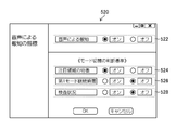
- FIG. 9 is a diagram showing an example of a setting screen of the notification mode by voice, and shows a state in which the setting unit 228 displays the screen 520 on the monitor 400.
- the screen 520 has areas 522 to 528 where radio buttons are arranged.
- the radio button By operating the radio button, the user can set whether or not to perform voice notification (on or off; area 522).
- the user can operate the radio button to "whether or not to switch the mode (first mode and second mode) according to the characteristics of the region of interest" (area 524) and "to the second mode according to the duration of the first mode".
- Whether or not to switch the mode (area 526) and "whether or not to switch the mode according to the inspection status (switching between the first mode and the second mode)" (area 528) can be set. ..
- the items of areas 524 to 528 (specific criteria for mode switching) can be set in detail via the screens (see FIGS. 10 to 13) described below. Further, switching between the first mode and the second mode is performed according to the determination result of the inspection status (described later).
- FIG. 10 is a diagram showing an example of a mode switching setting screen (details of the setting in the area 524 of FIG. 9) according to the characteristics of the region of interest, and shows a state in which the setting unit 228 displays the screen 530 on the monitor 400. ..
- the screen 530 has areas 532 to 542 in which radio buttons, numerical input areas, and pull-down menus are arranged. By operating the radio button, inputting or selecting a numerical value, the user can switch according to the size, shape, position, and number of the area of interest (areas 532 to 538, respectively) and the criteria for switching according to the disease type of the area of interest (area). 540,542) can be set.
- the notification unit 224 performs a second notification power lower than the first notification power. Notify in the second mode using the voice (continuation of the second mode).
- the size of the region of interest may be defined by the number of pixels.
- the area of interest is large, for example, in a situation where the user notices the area of interest and brings the tip (photographing unit) of the endoscope scope 100 closer to the area of interest.
- the size of the region of interest (the number of pixel values in the region of interest) in the image increases as the endoscope approaches the region of interest.
- the notification is performed in the first mode using the voice having the first notification power, the attention area approaches, and the size of the attention area is equal to or larger than the threshold value.
- the notification is performed in the second mode having the second notification power lower than the first notification power.
- the attention region smaller than the threshold value is detected after approaching the attention region once and performing the notification in the second mode, the notification is performed in the first mode.
- the notification may be continued in the first mode.
- FIG. 11 is a diagram showing an example of a mode switching setting screen (details of the setting in the area 526 of FIG. 9) according to the duration of the first mode, and shows a state in which the setting unit 228 displays the screen 550 on the monitor 400.
- the screen 550 has an area 552 in which a numerical value input area is arranged, and the user can continuously perform notification in the first mode for the same attention area by inputting a numerical value. Time spent; determination by determination unit 226) can be set.
- the notification in the first mode is performed for a set time or more (threshold value or more)
- the notification unit 224 switches to the second mode and performs voice notification.
- Switching modes according to the duration in this way is because if the notification in the first mode continues for a set time or longer, it is considered that the user has already noticed the area of interest, and in that situation, the notification power is high (first mode). This is because it can be a hindrance to continue the notification in.
- FIG. 12 is a diagram showing an example of a mode switching setting screen (details of the setting in the area 528 of FIG. 9) depending on the inspection status, and shows a state in which the setting unit 228 displays the screen 570 on the monitor 400.
- the screen 570 has areas 572 to 580 in which a numerical input area is arranged, and the user can turn on / off the mode switching according to the inspection status by operating a radio button. Specifically, when the radio button is turned on in the areas 572 to 580, the notification unit 224 is in the second mode when the medical image is being enlarged, displayed, dyed, observed with special light, treated, or washed. Notify at.
- the user is aware of the area of interest, or the need for notification is considered to be low.
- the user can turn on one or more of the radio buttons in the areas 572 to 580 (when all of them are to be turned off, that is, when the mode is not switched depending on the inspection status, the user can turn on the area 528 in FIG. You can turn off the radio button with ().
- FIG. 13 is a diagram showing an example of a setting screen of how to reduce the notification power in the second mode (comparison with the notification power in the first mode), and shows a state in which the setting unit 228 displays the screen 590 on the monitor 400.
- the screen 590 has areas 592 to 596 in which radio buttons are arranged, and the user can set one or more of volume reduction, pitch reduction, slow pitch, and voice notification stop by operating the radio buttons. it can.
- the image acquisition unit 220 acquires a time-series endoscopic image (medical image) (step S110: image acquisition step, execution of image acquisition function).
- the image acquisition unit 220 may acquire an endoscope image taken by the endoscope scope 100, or may acquire an endoscope image 260 recorded by the recording unit 207.
- the recording control unit 230 can record the acquired image as an endoscopic image 260 in the recording unit 207.
- the recognition unit 222 recognizes the region of interest in the endoscopic image acquired in step S110 (step S120: recognition step, execution of recognition function).
- the recognition unit 222 can perform one or more of detection, classification, and measurement by the above-mentioned CNN or the like.
- the region of interest (region of interest) to be detected include polyps, cancer, colonic diverticulum, inflammation, and treatment scars (EMR: Endoscopic Mucosal Resection).
- ESD scar ESD: Endoscopic Submucosal Dissection
- clip location etc.
- bleeding point perforation
- vascular atypia vascular atypia
- Examples of "differentiation" of the area of interest include the type of lesion (hyperplastic polyp, adenomas, intramucosal cancer, invasive cancer, etc.), the extent of the lesion, the size of the lesion, the macroscopic shape of the lesion, and the stage diagnosis of the cancer. , Current position in the lumen (upper part, pharynx, esophagus, stomach, duodenum, etc., lower part, cecum, ascending colon, transverse colon, descending colon, sigmoid colon, rectum, etc.) it can.
- Step S140 notification process, notification function
- Notification by screen display is performed, for example, when the setting is on (see area 502 in FIG. 8) and the time "from the detection of the area of interest to the start of notification" (see area 510 in FIG. 8) has elapsed. For example, when the setting is off, and when the setting is on, the time "from the detection of the region of interest to the start of notification" (see region 510 in FIG. 8) has not elapsed. It's time.
- Step S140 When performing notification by screen display (YES in step S140), the notification unit 224 switches from the non-notification state to the notification state, and the recognition result is determined according to the mode set in step S100 (for example, frame 604 or frame 606 in FIG. 12).
- Step S150 notification step, execution of notification function.
- the notification unit 224 performs notification by screen display regardless of the determination result of the inspection status, the screen display mode may be changed within a range that does not significantly affect the notification power. Further, when the region of interest is detected but the notification is not performed, the notification unit 224 may switch from the notification state to the non-notification state.
- the notification unit 224 determines whether or not to perform voice notification (step S160: notification step, execution of notification function).
- the voice notification is performed when the setting is on (see region 502 in FIG. 8).
- the notification unit 224 determines whether or not the notification power of the voice notification should be lowered, that is, whether the notification should be performed in the first mode or the second mode, according to the determination result in step S170 (step S180). : Notification process, execution of notification function).
- the notification unit 224 can determine step S180 according to the "mode switching determination criteria" set in step S100 (see regions 524 to 528 in FIG. 9; features of the region of interest in the example of FIG. 9).
- the notification unit 224 sets either the first mode or the second mode according to the determination result in step S180 (steps S190, S200: notification process, execution of notification function), and notifies by voice in the set mode.
- Step S210 notification step, execution of notification function.
- the notification unit 224 may switch from the first mode to the second mode or switch from the second mode to the first mode to perform voice notification according to the determination result of the inspection status. Further, the notification unit 224 may continue the notification in the first mode or the second mode depending on the determination result of the inspection status.
- the type of voice may be an electronic sound or a human voice. In the case of electronic sounds, sounds that are not confused with environmental sounds in the laboratory (heart rate monitor sounds, exhaust sounds, etc.) are preferable.
- FIG. 14 is a diagram showing an example of notification by screen display (step S150).
- the attention area 602 is displayed in the image display area 600 of the monitor 400, and the frame 604 surrounding the attention area 602 is displayed (the radio box is turned on in the area 504 of FIG. 8). If so) is shown.
- the part (b) of FIG. 14 is a state in which the frame 606 is displayed outside the image display area 600 (when the radio box is turned on in the area 506 of FIG. 8), and the part (c) of the figure is A state in which the star-shaped symbol 608 is displayed in the notification area 607 provided outside the image display area 600 is shown.
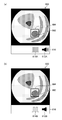
- FIG. 15 is a diagram showing a state of voice notification (step S210).
- the part (a) in FIG. 15 is an example showing the state of notification in the first mode.
- the notification mode display area 610 is provided outside the image display area 600, and the icon 612A (loud volume) indicating the volume of the voice output is provided.
- the icon 614A fast pitch and short cycle
- the part (b) in FIG. 15 is an example showing the notification state in the second mode, and the icon 612B (low volume) indicating the volume of the audio output and the icon 614B (on / off) indicating the pitch of the audio. The pitch is slow and the cycle is long) is displayed.
- the state shown in the portion (b) of FIG. 15 corresponds to the notification mode setting in FIG.
- the notification unit 224 may erase these icons and the notification mode display area 610 after a time determined from the start of notification or in response to a user operation via the operation unit 208 or the like.
- the image processing unit 204 repeats the processing of steps S110 to S210 until the processing is completed (until YES is obtained in step S220).
- the image processing unit 204 can end the processing according to the user's operation on the hand operation unit 102 or the operation unit 208, for example.
- the recognition unit 222 may recognize the region of interest without the image processing of the medical image (step S120: recognition). Process).
- the recognition unit 222 can recognize (detect, discriminate (classify), measure) the region of interest by, for example, voice input of the user, image recognition of gestures, or operation of a device such as a foot switch.
- notification and notification are given as in the above-described embodiment. This makes it possible for the user to fully recognize the operating state of the support function.
- the medical image analysis processing unit detects a region of interest, which is a region of interest, based on the feature amount of pixels of the medical image.
- the medical image analysis result acquisition unit is a medical image processing device that acquires the analysis results of the medical image analysis processing unit.
- the medical image analysis processing unit detects the presence or absence of a noteworthy object based on the feature amount of the pixel of the medical image.
- the medical image analysis result acquisition unit is a medical image processing device that acquires the analysis results of the medical image analysis processing unit.
- the medical image analysis result acquisition department Obtained from a recording device that records the analysis results of medical images
- the analysis result is a medical image processing apparatus that is a region of interest that is a region of interest included in a medical image, or a presence or absence of an object of interest, or both.
- a medical image is a medical image processing apparatus that is a normal light image obtained by irradiating light in a white band or light in a plurality of wavelength bands as light in a white band.
- a medical image is an image obtained by irradiating light in a specific wavelength band.
- a medical image processing device in which a specific wavelength band is narrower than the white wavelength band.
- a medical image processing device in which a specific wavelength band is a blue or green band in the visible range.
- the specific wavelength band includes a wavelength band of 585 nm or more and 615 nm or less or 610 nm or more and 730 nm or less, and the light of the specific wavelength band has a peak wavelength in the wavelength band of 585 nm or more and 615 nm or less or 610 nm or more and 730 nm or less.
- Image processing device includes a wavelength band of 585 nm or more and 615 nm or less or 610 nm or more and 730 nm or less, and the light of the specific wavelength band has a peak wavelength in the wavelength band of 585 nm or more and 615 nm or less or 610 nm or more and 730 nm or less.
- the specific wavelength band includes a wavelength band in which the absorption coefficient differs between the oxidized hemoglobin and the reduced hemoglobin, and the light in the specific wavelength band has a peak wavelength in the wavelength band in which the absorption coefficient differs between the oxidized hemoglobin and the reduced hemoglobin.
- Medical image processing device includes a wavelength band in which the absorption coefficient differs between the oxidized hemoglobin and the reduced hemoglobin, and the light in the specific wavelength band has a peak wavelength in the wavelength band in which the absorption coefficient differs between the oxidized hemoglobin and the reduced hemoglobin.
- the specific wavelength band includes 400 ⁇ 10 nm, 440 ⁇ 10 nm, 470 ⁇ 10 nm, or 600 nm or more and 750 nm or less, and the light in the specific wavelength band is 400 ⁇ 10 nm, 440 ⁇ 10 nm, 470 ⁇ .
- a medical image processing apparatus having a peak wavelength in a wavelength band of 10 nm or 600 nm or more and 750 nm or less.
- Fluorescence is a medical image processing device obtained by irradiating a living body with excitation light having a peak of 390 or more and 470 nm or less.
- a medical image in which a specific wavelength band includes a wavelength band of 790 nm or more and 820 nm or less or 905 nm or more and 970 nm or less, and light in a specific wavelength band has a peak wavelength in a wavelength band of 790 nm or more and 820 nm or less or 905 nm or more and 970 nm or less. Processing equipment.
- Appendix 17 A medical image processing device that obtains a signal in a specific wavelength band by calculation based on RGB or CMY color information included in a normal optical image.
- Appendix 18 By calculation based on at least one of a normal light image obtained by irradiating light in a white band or light in a plurality of wavelength bands as light in a white band and a special light image obtained by irradiating light in a specific wavelength band. Equipped with a feature amount image generator that generates a feature amount image A medical image is a medical image processing device that is a feature image.
Landscapes
- Health & Medical Sciences (AREA)
- Life Sciences & Earth Sciences (AREA)
- Surgery (AREA)
- Engineering & Computer Science (AREA)
- Public Health (AREA)
- Medical Informatics (AREA)
- General Health & Medical Sciences (AREA)
- Biomedical Technology (AREA)
- Pathology (AREA)
- Radiology & Medical Imaging (AREA)
- Nuclear Medicine, Radiotherapy & Molecular Imaging (AREA)
- Optics & Photonics (AREA)
- Heart & Thoracic Surgery (AREA)
- Molecular Biology (AREA)
- Animal Behavior & Ethology (AREA)
- Physics & Mathematics (AREA)
- Biophysics (AREA)
- Veterinary Medicine (AREA)
- Epidemiology (AREA)
- Primary Health Care (AREA)
- Data Mining & Analysis (AREA)
- Databases & Information Systems (AREA)
- Signal Processing (AREA)
- Endoscopes (AREA)
Priority Applications (2)
| Application Number | Priority Date | Filing Date | Title |
|---|---|---|---|
| JP2021539230A JP7290729B2 (ja) | 2019-08-13 | 2020-08-05 | 画像診断支援装置、内視鏡システム、画像診断支援装置の作動方法、及び画像診断支援プログラム |
| US17/591,343 US12588799B2 (en) | 2019-08-13 | 2022-02-02 | Image diagnosis assistance apparatus, endoscope system, image diagnosis assistance method, and image diagnosis assistance program |
Applications Claiming Priority (2)
| Application Number | Priority Date | Filing Date | Title |
|---|---|---|---|
| JP2019148334 | 2019-08-13 | ||
| JP2019-148334 | 2019-08-13 |
Related Child Applications (1)
| Application Number | Title | Priority Date | Filing Date |
|---|---|---|---|
| US17/591,343 Continuation US12588799B2 (en) | 2019-08-13 | 2022-02-02 | Image diagnosis assistance apparatus, endoscope system, image diagnosis assistance method, and image diagnosis assistance program |
Publications (1)
| Publication Number | Publication Date |
|---|---|
| WO2021029292A1 true WO2021029292A1 (ja) | 2021-02-18 |
Family
ID=74570391
Family Applications (1)
| Application Number | Title | Priority Date | Filing Date |
|---|---|---|---|
| PCT/JP2020/029967 Ceased WO2021029292A1 (ja) | 2019-08-13 | 2020-08-05 | 画像診断支援装置、内視鏡システム、画像診断支援方法、及び画像診断支援プログラム |
Country Status (3)
| Country | Link |
|---|---|
| US (1) | US12588799B2 (https=) |
| JP (1) | JP7290729B2 (https=) |
| WO (1) | WO2021029292A1 (https=) |
Cited By (5)
| Publication number | Priority date | Publication date | Assignee | Title |
|---|---|---|---|---|
| JPWO2022186109A1 (https=) * | 2021-03-01 | 2022-09-09 | ||
| WO2022202430A1 (ja) * | 2021-03-23 | 2022-09-29 | 富士フイルム株式会社 | 医用画像処理装置、医用画像処理方法、及びプログラム |
| JPWO2022264751A1 (https=) * | 2021-06-16 | 2022-12-22 | ||
| WO2022270582A1 (ja) * | 2021-06-24 | 2022-12-29 | 株式会社Aiメディカルサービス | 検査支援装置、検査支援方法および検査支援プログラム |
| WO2026069468A1 (ja) * | 2024-09-25 | 2026-04-02 | 日本電気株式会社 | 内視鏡検査支援装置、内視鏡検査支援方法、及び、記録媒体 |
Families Citing this family (2)
| Publication number | Priority date | Publication date | Assignee | Title |
|---|---|---|---|---|
| EP3838109A4 (en) * | 2018-08-17 | 2021-10-06 | FUJIFILM Corporation | ENDOSCOPIC SYSTEM |
| US12053160B2 (en) | 2020-01-10 | 2024-08-06 | Nec Corporation | Endoscopy support apparatus, endoscopy support method, and computer readable recording medium |
Citations (6)
| Publication number | Priority date | Publication date | Assignee | Title |
|---|---|---|---|---|
| WO2005011501A1 (ja) * | 2003-08-01 | 2005-02-10 | Hitachi Medical Corporation | 医用画像診断支援装置及び方法 |
| JP2006129950A (ja) * | 2004-11-02 | 2006-05-25 | Olympus Corp | 画像表示装置、画像表示方法および画像表示プログラム |
| JP2015112429A (ja) * | 2013-12-13 | 2015-06-22 | オリンパスメディカルシステムズ株式会社 | 画像処理装置 |
| JP2016540552A (ja) * | 2013-11-01 | 2016-12-28 | コーニンクレッカ フィリップス エヌ ヴェKoninklijke Philips N.V. | 音響アラーム検出及び妥当性検証のための装置及び方法 |
| WO2018179991A1 (ja) * | 2017-03-30 | 2018-10-04 | 富士フイルム株式会社 | 内視鏡システム及びその作動方法 |
| WO2019078102A1 (ja) * | 2017-10-20 | 2019-04-25 | 富士フイルム株式会社 | 医療画像処理装置 |
Family Cites Families (5)
| Publication number | Priority date | Publication date | Assignee | Title |
|---|---|---|---|---|
| JP4388318B2 (ja) * | 2003-06-27 | 2009-12-24 | オリンパス株式会社 | 画像処理装置 |
| KR100961591B1 (ko) * | 2004-08-30 | 2010-06-04 | 올림푸스 가부시키가이샤 | 내시경 장치 |
| KR100927286B1 (ko) * | 2005-06-08 | 2009-11-18 | 올림푸스 메디칼 시스템즈 가부시키가이샤 | 내시경 장치 및 화상 처리 장치 |
| JP5597021B2 (ja) * | 2010-04-15 | 2014-10-01 | オリンパス株式会社 | 画像処理装置及びプログラム |
| JP2019180966A (ja) * | 2018-04-13 | 2019-10-24 | 学校法人昭和大学 | 内視鏡観察支援装置、内視鏡観察支援方法、及びプログラム |
-
2020
- 2020-08-05 JP JP2021539230A patent/JP7290729B2/ja active Active
- 2020-08-05 WO PCT/JP2020/029967 patent/WO2021029292A1/ja not_active Ceased
-
2022
- 2022-02-02 US US17/591,343 patent/US12588799B2/en active Active
Patent Citations (6)
| Publication number | Priority date | Publication date | Assignee | Title |
|---|---|---|---|---|
| WO2005011501A1 (ja) * | 2003-08-01 | 2005-02-10 | Hitachi Medical Corporation | 医用画像診断支援装置及び方法 |
| JP2006129950A (ja) * | 2004-11-02 | 2006-05-25 | Olympus Corp | 画像表示装置、画像表示方法および画像表示プログラム |
| JP2016540552A (ja) * | 2013-11-01 | 2016-12-28 | コーニンクレッカ フィリップス エヌ ヴェKoninklijke Philips N.V. | 音響アラーム検出及び妥当性検証のための装置及び方法 |
| JP2015112429A (ja) * | 2013-12-13 | 2015-06-22 | オリンパスメディカルシステムズ株式会社 | 画像処理装置 |
| WO2018179991A1 (ja) * | 2017-03-30 | 2018-10-04 | 富士フイルム株式会社 | 内視鏡システム及びその作動方法 |
| WO2019078102A1 (ja) * | 2017-10-20 | 2019-04-25 | 富士フイルム株式会社 | 医療画像処理装置 |
Cited By (13)
| Publication number | Priority date | Publication date | Assignee | Title |
|---|---|---|---|---|
| JP7752678B2 (ja) | 2021-03-01 | 2025-10-10 | 富士フイルム株式会社 | 医療画像処理装置、内視鏡システム、医療画像処理方法、及び医療画像処理プログラム |
| WO2022186109A1 (ja) * | 2021-03-01 | 2022-09-09 | 富士フイルム株式会社 | 医療画像処理装置、内視鏡システム、医療画像処理方法、及び医療画像処理プログラム |
| JPWO2022186109A1 (https=) * | 2021-03-01 | 2022-09-09 | ||
| CN116887745A (zh) * | 2021-03-01 | 2023-10-13 | 富士胶片株式会社 | 医疗图像处理装置、内窥镜系统、医疗图像处理方法及医疗图像处理程序 |
| EP4302680A4 (en) * | 2021-03-01 | 2024-08-07 | FUJIFILM Corporation | Medical image processing device, endoscope system, medical image processing method, and medical image processing program |
| WO2022202430A1 (ja) * | 2021-03-23 | 2022-09-29 | 富士フイルム株式会社 | 医用画像処理装置、医用画像処理方法、及びプログラム |
| JPWO2022202430A1 (https=) * | 2021-03-23 | 2022-09-29 | ||
| JPWO2022264751A1 (https=) * | 2021-06-16 | 2022-12-22 | ||
| JP7846107B2 (ja) | 2021-06-16 | 2026-04-14 | 富士フイルム株式会社 | 医用画像処理装置、医用画像処理方法、及びプログラム |
| JP2023003458A (ja) * | 2021-06-24 | 2023-01-17 | 株式会社Aiメディカルサービス | 検査支援装置、検査支援方法および検査支援プログラム |
| JP7617622B2 (ja) | 2021-06-24 | 2025-01-20 | 株式会社Aiメディカルサービス | 検査支援装置、検査支援方法および検査支援プログラム |
| WO2022270582A1 (ja) * | 2021-06-24 | 2022-12-29 | 株式会社Aiメディカルサービス | 検査支援装置、検査支援方法および検査支援プログラム |
| WO2026069468A1 (ja) * | 2024-09-25 | 2026-04-02 | 日本電気株式会社 | 内視鏡検査支援装置、内視鏡検査支援方法、及び、記録媒体 |
Also Published As
| Publication number | Publication date |
|---|---|
| US12588799B2 (en) | 2026-03-31 |
| JP7290729B2 (ja) | 2023-06-13 |
| JPWO2021029292A1 (https=) | 2021-02-18 |
| US20220151462A1 (en) | 2022-05-19 |
Similar Documents
| Publication | Publication Date | Title |
|---|---|---|
| JP7629050B2 (ja) | 内視鏡システム及び内視鏡システムの作動方法 | |
| JP7290729B2 (ja) | 画像診断支援装置、内視鏡システム、画像診断支援装置の作動方法、及び画像診断支援プログラム | |
| JP7346285B2 (ja) | 医療画像処理装置、内視鏡システム、医療画像処理装置の作動方法及びプログラム | |
| JP7170032B2 (ja) | 画像処理装置、内視鏡システム、及び画像処理方法 | |
| US20210235980A1 (en) | Medical-use image processing device, endoscope system, and medical-use image processing method | |
| JP7038641B2 (ja) | 医療診断支援装置、内視鏡システム、及び作動方法 | |
| JP2023026480A (ja) | 医療画像処理装置、内視鏡システム、及び医療画像処理装置の作動方法 | |
| JP7507797B2 (ja) | 医用画像処理装置、内視鏡システム、医用画像処理装置の作動方法、プログラム、及び記録媒体 | |
| JPWO2019220859A1 (ja) | 画像処理装置、内視鏡システム、及び画像処理方法 | |
| JP7752678B2 (ja) | 医療画像処理装置、内視鏡システム、医療画像処理方法、及び医療画像処理プログラム | |
| US20250151974A1 (en) | Medical image processing apparatus, endoscope system, and medical image processing method | |
| JP7558982B2 (ja) | 医療画像処理装置、内視鏡システム、及び医療画像処理装置の作動方法 | |
| JP7774610B2 (ja) | 医療画像処理装置、内視鏡システム、医療画像処理方法、医療画像処理プログラム、及び記録媒体 | |
| JPWO2020059445A1 (ja) | 画像処理装置及び画像処理方法 | |
| JPWO2022181748A5 (https=) | ||
| JP7594015B2 (ja) | 医療画像処理装置、医療画像処理装置の作動方法、内視鏡システム、及び医療画像処理プログラム |
Legal Events
| Date | Code | Title | Description |
|---|---|---|---|
| 121 | Ep: the epo has been informed by wipo that ep was designated in this application |
Ref document number: 20852827 Country of ref document: EP Kind code of ref document: A1 |
|
| WWE | Wipo information: entry into national phase |
Ref document number: 2021539230 Country of ref document: JP |
|
| NENP | Non-entry into the national phase |
Ref country code: DE |
|
| 122 | Ep: pct application non-entry in european phase |
Ref document number: 20852827 Country of ref document: EP Kind code of ref document: A1 |