WO2021029234A1 - 超音波システムおよび超音波システムの制御方法 - Google Patents
超音波システムおよび超音波システムの制御方法 Download PDFInfo
- Publication number
- WO2021029234A1 WO2021029234A1 PCT/JP2020/029424 JP2020029424W WO2021029234A1 WO 2021029234 A1 WO2021029234 A1 WO 2021029234A1 JP 2020029424 W JP2020029424 W JP 2020029424W WO 2021029234 A1 WO2021029234 A1 WO 2021029234A1
- Authority
- WO
- WIPO (PCT)
- Prior art keywords
- ultrasonic
- image
- probe
- external
- terminal
- Prior art date
Links
Images


Classifications
-
- A—HUMAN NECESSITIES
- A61—MEDICAL OR VETERINARY SCIENCE; HYGIENE
- A61B—DIAGNOSIS; SURGERY; IDENTIFICATION
- A61B8/00—Diagnosis using ultrasonic, sonic or infrasonic waves
- A61B8/56—Details of data transmission or power supply
- A61B8/565—Details of data transmission or power supply involving data transmission via a network
-
- A—HUMAN NECESSITIES
- A61—MEDICAL OR VETERINARY SCIENCE; HYGIENE
- A61B—DIAGNOSIS; SURGERY; IDENTIFICATION
- A61B8/00—Diagnosis using ultrasonic, sonic or infrasonic waves
- A61B8/44—Constructional features of the ultrasonic, sonic or infrasonic diagnostic device
-
- A—HUMAN NECESSITIES
- A61—MEDICAL OR VETERINARY SCIENCE; HYGIENE
- A61B—DIAGNOSIS; SURGERY; IDENTIFICATION
- A61B8/00—Diagnosis using ultrasonic, sonic or infrasonic waves
- A61B8/44—Constructional features of the ultrasonic, sonic or infrasonic diagnostic device
- A61B8/4483—Constructional features of the ultrasonic, sonic or infrasonic diagnostic device characterised by features of the ultrasound transducer
- A61B8/4494—Constructional features of the ultrasonic, sonic or infrasonic diagnostic device characterised by features of the ultrasound transducer characterised by the arrangement of the transducer elements
-
- A—HUMAN NECESSITIES
- A61—MEDICAL OR VETERINARY SCIENCE; HYGIENE
- A61B—DIAGNOSIS; SURGERY; IDENTIFICATION
- A61B8/00—Diagnosis using ultrasonic, sonic or infrasonic waves
- A61B8/44—Constructional features of the ultrasonic, sonic or infrasonic diagnostic device
- A61B8/4444—Constructional features of the ultrasonic, sonic or infrasonic diagnostic device related to the probe
- A61B8/4472—Wireless probes
-
- A—HUMAN NECESSITIES
- A61—MEDICAL OR VETERINARY SCIENCE; HYGIENE
- A61B—DIAGNOSIS; SURGERY; IDENTIFICATION
- A61B8/00—Diagnosis using ultrasonic, sonic or infrasonic waves
- A61B8/44—Constructional features of the ultrasonic, sonic or infrasonic diagnostic device
- A61B8/4483—Constructional features of the ultrasonic, sonic or infrasonic diagnostic device characterised by features of the ultrasound transducer
- A61B8/4488—Constructional features of the ultrasonic, sonic or infrasonic diagnostic device characterised by features of the ultrasound transducer the transducer being a phased array
-
- A—HUMAN NECESSITIES
- A61—MEDICAL OR VETERINARY SCIENCE; HYGIENE
- A61B—DIAGNOSIS; SURGERY; IDENTIFICATION
- A61B8/00—Diagnosis using ultrasonic, sonic or infrasonic waves
- A61B8/46—Ultrasonic, sonic or infrasonic diagnostic devices with special arrangements for interfacing with the operator or the patient
- A61B8/461—Displaying means of special interest
- A61B8/462—Displaying means of special interest characterised by constructional features of the display
-
- A—HUMAN NECESSITIES
- A61—MEDICAL OR VETERINARY SCIENCE; HYGIENE
- A61B—DIAGNOSIS; SURGERY; IDENTIFICATION
- A61B8/00—Diagnosis using ultrasonic, sonic or infrasonic waves
- A61B8/46—Ultrasonic, sonic or infrasonic diagnostic devices with special arrangements for interfacing with the operator or the patient
- A61B8/461—Displaying means of special interest
- A61B8/463—Displaying means of special interest characterised by displaying multiple images or images and diagnostic data on one display
-
- A—HUMAN NECESSITIES
- A61—MEDICAL OR VETERINARY SCIENCE; HYGIENE
- A61B—DIAGNOSIS; SURGERY; IDENTIFICATION
- A61B8/00—Diagnosis using ultrasonic, sonic or infrasonic waves
- A61B8/46—Ultrasonic, sonic or infrasonic diagnostic devices with special arrangements for interfacing with the operator or the patient
- A61B8/461—Displaying means of special interest
- A61B8/465—Displaying means of special interest adapted to display user selection data, e.g. icons or menus
-
- A—HUMAN NECESSITIES
- A61—MEDICAL OR VETERINARY SCIENCE; HYGIENE
- A61B—DIAGNOSIS; SURGERY; IDENTIFICATION
- A61B8/00—Diagnosis using ultrasonic, sonic or infrasonic waves
- A61B8/46—Ultrasonic, sonic or infrasonic diagnostic devices with special arrangements for interfacing with the operator or the patient
- A61B8/467—Ultrasonic, sonic or infrasonic diagnostic devices with special arrangements for interfacing with the operator or the patient characterised by special input means
-
- A—HUMAN NECESSITIES
- A61—MEDICAL OR VETERINARY SCIENCE; HYGIENE
- A61B—DIAGNOSIS; SURGERY; IDENTIFICATION
- A61B8/00—Diagnosis using ultrasonic, sonic or infrasonic waves
- A61B8/52—Devices using data or image processing specially adapted for diagnosis using ultrasonic, sonic or infrasonic waves
- A61B8/5207—Devices using data or image processing specially adapted for diagnosis using ultrasonic, sonic or infrasonic waves involving processing of raw data to produce diagnostic data, e.g. for generating an image
-
- A—HUMAN NECESSITIES
- A61—MEDICAL OR VETERINARY SCIENCE; HYGIENE
- A61B—DIAGNOSIS; SURGERY; IDENTIFICATION
- A61B8/00—Diagnosis using ultrasonic, sonic or infrasonic waves
- A61B8/54—Control of the diagnostic device
-
- G—PHYSICS
- G16—INFORMATION AND COMMUNICATION TECHNOLOGY [ICT] SPECIALLY ADAPTED FOR SPECIFIC APPLICATION FIELDS
- G16H—HEALTHCARE INFORMATICS, i.e. INFORMATION AND COMMUNICATION TECHNOLOGY [ICT] SPECIALLY ADAPTED FOR THE HANDLING OR PROCESSING OF MEDICAL OR HEALTHCARE DATA
- G16H40/00—ICT specially adapted for the management or administration of healthcare resources or facilities; ICT specially adapted for the management or operation of medical equipment or devices
- G16H40/60—ICT specially adapted for the management or administration of healthcare resources or facilities; ICT specially adapted for the management or operation of medical equipment or devices for the operation of medical equipment or devices
- G16H40/67—ICT specially adapted for the management or administration of healthcare resources or facilities; ICT specially adapted for the management or operation of medical equipment or devices for the operation of medical equipment or devices for remote operation
Definitions
- the present invention relates to an ultrasonic system and a control method of an ultrasonic system, and more particularly to an ultrasonic system and a control method of an ultrasonic system for displaying an ultrasonic image on a personal digital assistant.
- this type of ultrasonic diagnostic apparatus has an ultrasonic probe having a built-in transducer array and an apparatus main body connected to the ultrasonic probe, and ultrasonic waves are directed from the ultrasonic probe toward a subject. Is transmitted, the ultrasonic echo from the subject is received by the ultrasonic probe, and the received signal is electrically processed by the main body of the apparatus to generate an ultrasonic image.
- Patent Document 1 an ultrasonic image acquired by using an ultrasonic probe is displayed on an external monitor arranged at a position away from the user, and the ultrasonic probe and the external monitor are displayed.
- An ultrasonic diagnostic apparatus has been developed to improve the convenience in ultrasonic diagnosis by providing a portable information terminal for performing the input operation of.
- an ultrasonic image is taken in a remote place outside the hospital such as at home nursing
- an operator who operates an ultrasonic probe to take an ultrasonic image and an ultrasonic image taken are shown.
- Observers such as doctors who observe and make a diagnosis may differ.
- the operator usually needs to operate the ultrasonic probe while checking the obtained ultrasonic image by himself / herself to take an ultrasonic image of the target site in the subject.
- the skill level of the operator is low, it may be difficult for the operator to determine whether or not the target site of the subject can be accurately observed.
- an operator with a low skill level may not be able to operate the ultrasonic probe by using an appropriate technique, and an ultrasonic image with low image quality may be obtained.
- the observer confirms the ultrasonic image taken by the operator of the ultrasonic diagnostic apparatus to make a diagnosis, but since the operator cannot grasp how the ultrasonic image is taken, the skill level is particularly high. When an ultrasonic image was taken by a low-level operator, it was sometimes difficult to accurately determine whether or not the captured ultrasonic image was taken by an appropriate procedure.
- the present invention has been made to solve such a conventional problem, and even when an ultrasonic image is taken at a remote place, an appropriate ultrasonic image can be obtained and ultrasonic diagnosis is performed. It is an object of the present invention to provide an ultrasonic system and a control method of an ultrasonic system capable of improving the accuracy of the ultrasonic system.
- the first ultrasonic system is an ultrasonic system including an ultrasonic probe, a portable information terminal, and an external device, and the ultrasonic probe includes an oscillator array and a vibrator array.
- a transmitter / receiver circuit that transmits ultrasonic waves from the transducer array and generates a sound line signal based on the received signal acquired by the transducer array, and an ultrasonic image is generated based on the sound line signal generated by the transmitter / receiver circuit.
- the mobile information terminal includes a camera unit and a camera unit that acquires a field image of the scanned portion of the ultrasonic probe in the subject, including an ultrasonic image generation unit and a probe-side wireless communication unit that wirelessly transmits the ultrasonic image.
- the external device includes at least an external wireless communication unit wirelessly connected to the terminal side wireless communication unit, an external monitor, and an ultrasonic probe, including a terminal-side wireless communication unit that wirelessly transmits the field image acquired by the unit. It includes a display control unit that displays the transmitted ultrasonic image and the field image wirelessly transmitted from the mobile information terminal on an external monitor, and an external input device.
- a probe freeze instruction is input from the external input device, the probe The freeze instruction is transmitted from the external wireless communication unit, and the transmission of ultrasonic waves from the transducer array by the transmission / reception circuit of the ultrasonic probe is stopped.
- the probe freeze instruction is transmitted from the external wireless communication unit to the probe side wireless communication unit via the terminal side wireless communication unit.
- the acquisition of the visual field image by the camera unit of the portable information terminal is stopped.
- the probe freeze instruction can be transmitted from the external wireless communication unit to the probe side wireless communication unit.
- the external wireless communication unit is wirelessly connected to both the probe-side wireless communication unit and the terminal-side wireless communication unit, and the probe-side wireless communication unit can wirelessly transmit an ultrasonic image to both the mobile information terminal and the external device. ..
- the probe-side wireless communication unit wirelessly transmits an ultrasonic image to the mobile information terminal
- the terminal-side wireless communication unit wirelessly transmits an ultrasonic image from the probe-side wireless communication unit and a field image acquired by the camera unit. Can also be wirelessly transmitted to an external device.
- the external monitor includes a microphone, and the suspension of ultrasonic wave transmission from the oscillator array can be released by the sound input through the microphone.
- the external device can include an image synchronization unit that synchronizes the ultrasonic image and the visual field image with each other.
- the external device is stored in the image memory and the image memory for storing the ultrasonic image and the field image synchronized with each other by the image synchronization unit.
- It can include a thumbnail image generation unit that generates a plurality of thumbnail images composed of an ultrasonic image and a field image and displays a list of the generated plurality of thumbnail images on an external monitor.
- the portable information terminal includes a terminal monitor, and an ultrasonic image and a visual field image can be displayed on the terminal monitor.
- the mobile information terminal includes the terminal input device, and when the probe freeze instruction is input from the external input device or the terminal input device, the fact that the probe freeze instruction is given is displayed on the external monitor and the terminal monitor. Can be done.
- the external input device has a touch sensor arranged on the external monitor
- the terminal input device has a touch sensor arranged on the terminal monitor
- the probe please from the external input device or the terminal input device.
- the release button displayed on the external monitor the indication that the probe freeze instruction is displayed on the external monitor
- the release button displayed on the terminal monitor By touching any of the indications indicating that the probe freezes, the stop of transmission of ultrasonic waves from the transducer array can be released.
- the portable information terminal may include a microphone, and the stop of transmission of ultrasonic waves from the vibrator array can be released by the voice input through the microphone.
- the portable information terminal can include an image synchronization unit that synchronizes the ultrasonic image and the visual field image with each other.
- the external wireless communication unit can wirelessly transmit the external advice information input via the external input device to the terminal side wireless communication unit, and the external advice information can be displayed on the terminal monitor.
- the external device can include a measuring unit that analyzes the ultrasonic image and measures the measurement object in the ultrasonic image.
- the portable information terminal may include a measuring unit that analyzes the ultrasonic image and measures the measurement object in the ultrasonic image.
- it is equipped with a mobile information terminal and a server connected to an external device.
- the server can also include a measuring unit that analyzes the ultrasonic image and measures the object to be measured in the ultrasonic image.
- voice data can be bidirectionally wirelessly communicated between the terminal-side wireless communication unit and the external wireless communication unit.
- the first method for controlling an ultrasonic system is a method for controlling an ultrasonic system including an ultrasonic probe, a portable information terminal, and an external device.
- the ultrasonic probe the transducer array of the ultrasonic probe.
- Ultrasound is transmitted from and a sound line signal is generated based on the received signal acquired by the transducer array, an ultrasonic image is generated based on the generated sound line signal, and the ultrasonic image is transmitted wirelessly.
- a field image obtained by capturing the scanning portion of the ultrasonic probe in the subject is acquired, the acquired field image is wirelessly transmitted, and in an external device, the ultrasonic image wirelessly transmitted from the ultrasonic probe and the portable information terminal.
- the probe freeze instruction is transmitted from the external device and the ultrasonic probe oscillator array. It is characterized in that the transmission of ultrasonic waves from is stopped.
- the second ultrasonic system is an ultrasonic system including an ultrasonic probe, a portable information terminal, and an external device, and the ultrasonic probe transmits ultrasonic waves from the vibrator array and the vibrator array.
- a transmission / reception circuit that generates a sound line signal based on the reception signal acquired by the oscillator array, and a reception that generates reception data before imaging by performing signal processing on the sound line signal generated by the transmission / reception circuit.
- the mobile information terminal includes a data generation unit and a probe-side wireless communication unit that wirelessly transmits received data, and the mobile information terminal acquires the field image obtained by capturing the scanning portion of the ultrasonic probe in the subject, and the camera unit.
- the external device includes at least the external wireless communication unit wirelessly connected to the terminal side wireless communication unit, the external monitor, and the ultrasonic probe, which includes the terminal-side wireless communication unit that wirelessly transmits the field image.
- a probe freeze instruction is input from the external input device, including a display control unit that displays the ultrasonic image generated based on the received data and the field image wirelessly transmitted from the mobile information terminal on the external monitor, and an external input device. When this is done, the probe freeze instruction is transmitted from the external wireless communication unit, and the transmission of ultrasonic waves from the transducer array by the transmission / reception circuit of the ultrasonic probe is stopped.
- the probe freeze instruction is transmitted from the external wireless communication unit to the probe side wireless communication unit via the terminal side wireless communication unit.
- the acquisition of the visual field image by the camera unit of the mobile information terminal can be stopped.
- the probe freeze instruction can be transmitted from the external wireless communication unit to the probe side wireless communication unit.
- the external wireless communication unit may be wirelessly connected to both the probe-side wireless communication unit and the terminal-side wireless communication unit, and the probe-side wireless communication unit may wirelessly transmit the received data to both the mobile information terminal and the external device. It can.
- the probe-side wireless communication unit wirelessly transmits the received data to the mobile information terminal
- the terminal-side wireless communication unit wirelessly transmits the ultrasonic image from the probe-side wireless communication unit and the field image acquired by the camera unit.
- the external device can include an image processing unit that generates an ultrasonic image based on received data wirelessly transmitted from the probe-side wireless communication unit.
- the probe-side wireless communication unit wirelessly transmits the received data to the mobile information terminal, and the mobile information terminal provides an image processing unit that generates an ultrasonic image based on the received data wirelessly transmitted from the probe-side wireless communication unit.
- the terminal-side wireless communication unit can also wirelessly transmit the ultrasonic image generated by the image processing unit and the field image acquired by the camera unit to an external device.
- the external monitor includes a microphone, and the suspension of ultrasonic wave transmission from the oscillator array can be released by the sound input through the microphone.
- the external device can include an image synchronization unit that synchronizes the ultrasonic image and the visual field image with each other.
- the external device is stored in the image memory and the image memory for storing the ultrasonic image and the field image synchronized with each other by the image synchronization unit.
- It can include a thumbnail image generation unit that generates a plurality of thumbnail images composed of an ultrasonic image and a field image and displays a list of the generated plurality of thumbnail images on an external monitor.
- the portable information terminal includes a terminal monitor, and an ultrasonic image and a visual field image can be displayed on the terminal monitor.
- the mobile information terminal includes the terminal input device, and when the probe freeze instruction is input from the external input device or the terminal input device, the fact that the probe freeze instruction is given is displayed on the external monitor and the terminal monitor. Is preferable.
- the external input device has a touch sensor arranged on the external monitor
- the terminal input device has a touch sensor arranged on the terminal monitor, and the probe freezes from the external input device or the terminal input device.
- the release button displayed on the external monitor the indication that the probe freeze instruction is displayed on the external monitor
- the release button displayed on the terminal monitor By touching any of the indications indicating that the probe freezes, the stop of transmission of ultrasonic waves from the transducer array can be released.
- the portable information terminal may include a microphone, and the stop of transmission of ultrasonic waves from the vibrator array can be released by the voice input through the microphone.
- the portable information terminal can include an image synchronization unit that synchronizes the ultrasonic image and the visual field image with each other.
- the external wireless communication unit can wirelessly transmit the external advice information input via the external input device to the terminal side wireless communication unit, and the external advice information can be displayed on the terminal monitor.
- the external device can include a measuring unit that analyzes the ultrasonic image and measures the measurement object in the ultrasonic image.
- the portable information terminal may include a measuring unit that analyzes the ultrasonic image and measures the measurement object in the ultrasonic image.
- the server may include a mobile information terminal and a server connected to an external device, and the server may include a measuring unit that analyzes the ultrasonic image and measures the measurement object in the ultrasonic image.
- voice data can be bidirectionally wirelessly communicated between the terminal-side wireless communication unit and the external wireless communication unit.
- the second method for controlling an ultrasonic system is a method for controlling an ultrasonic system including an ultrasonic probe, a portable information terminal, and an external device.
- the transducer array of the ultrasonic probe In the ultrasonic probe, the transducer array of the ultrasonic probe. Ultrasound is transmitted from and a sound line signal is generated based on the received signal acquired by the transducer array, an ultrasonic image is generated based on the generated sound line signal, and the ultrasonic image is transmitted wirelessly.
- a field image obtained by capturing the scanning portion of the ultrasonic probe in the subject is acquired, the acquired field image is wirelessly transmitted, and in an external device, the ultrasonic image wirelessly transmitted from the ultrasonic probe and the portable information terminal.
- the probe freeze instruction is transmitted from the external device and the ultrasonic probe oscillator array. It is characterized in that the transmission of ultrasonic waves from is stopped.
- the external device is wirelessly transmitted from at least the external wireless communication unit wirelessly communicated to the terminal side wireless communication unit, the external monitor, the ultrasonic image wirelessly transmitted from the ultrasonic probe, and the mobile information terminal.
- the display control unit that displays the field image on the external monitor includes an external input device, and when a probe freeze instruction is input from the external input device, the probe freeze instruction is transmitted from the external wireless communication unit, and the ultrasonic probe Since the transmission of ultrasonic waves from the transducer array by the transmission / reception circuit is stopped, an appropriate ultrasonic image can be obtained and the accuracy of ultrasonic diagnosis is improved even when an ultrasonic image is taken at a remote location. can do.
- Embodiment 1 of this invention It is a block diagram which shows the structure of the ultrasonic system which concerns on Embodiment 1 of this invention. It is a block diagram which shows the internal structure of the transmission / reception circuit in Embodiment 1 of this invention. It is a figure which shows typically the example of the mobile information terminal in Embodiment 1 of this invention. It is a figure which shows typically the example of the external device in Embodiment 1 of this invention. It is a figure which shows the example of the message which shows that the transmission of ultrasonic waves was stopped, which was displayed on the terminal monitor in the modification of Embodiment 1 of this invention.
- Embodiment 7 of this invention It is a block diagram which shows the structure of the external device in Embodiment 7 of this invention. It is a schematic diagram which shows the example of the thumbnail image displayed on the external monitor in Embodiment 7 of this invention. It is a block diagram which shows the structure of the external device in Embodiment 8 of this invention. It is a block diagram which shows the structure of the ultrasonic system which concerns on the modification of Embodiment 8 of this invention.
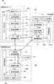
- FIG. 1 shows the configuration of the ultrasonic system 1 according to the first embodiment of the present invention.
- the ultrasonic system 1 includes an ultrasonic probe 2, a portable information terminal 3, and an external device 4.
- the mobile information terminal 3 and the external device 4 are connected to the ultrasonic probe 2 by wireless communication, and the mobile information terminal 3 and the external device 4 are connected to each other by wireless communication.
- the ultrasonic probe 2 includes an oscillator array 21, and a transmission / reception circuit 22, a signal processing unit 23, and a probe-side wireless communication unit 24 are sequentially connected to the oscillator array 21.
- the probe-side wireless communication unit 24 is connected to the mobile information terminal 3 and the external device 4 by wireless communication.
- the signal processing unit 23 constitutes a reception data generation unit.
- the probe control unit 26 is connected to the transmission / reception circuit 22, the signal processing unit 23, and the probe side wireless communication unit 24.
- the probe side processor 27 is composed of the signal processing unit 23, the probe side wireless communication unit 24, and the probe control unit 26.
- the mobile information terminal 3 includes a terminal-side wireless communication unit 31 connected to the ultrasonic probe 2 and the external device 4 by wireless communication, and the image processing unit 32 is connected to the terminal-side wireless communication unit 31. Further, the mobile information terminal 3 includes a camera unit 33, and the camera unit 33 is connected to the terminal side wireless communication unit 31. Further, the image synchronization unit 34 is connected to the image processing unit 32 and the camera unit 33. Further, the display control unit 35 and the terminal monitor 36 are sequentially connected to the image synchronization unit 34. Further, the terminal control unit 37 is connected to the terminal side wireless communication unit 31, the image processing unit 32, the camera unit 33, the image synchronization unit 34, and the display control unit 35. Further, an input device (terminal input device) 38 is connected to the terminal control unit 37. Further, the terminal side processor 39 is composed of the terminal side wireless communication unit 31, the image processing unit 32, the image synchronization unit 34, the display control unit 35, and the terminal control unit 37.
- the external device 4 includes an external wireless communication unit 41 that is connected to the ultrasonic probe 2 and the mobile information terminal 3 by wireless communication, and the image processing unit 42 and the image synchronization unit 43 are connected to the external wireless communication unit 41. ing. Further, the image processing unit 42 is connected to the image synchronization unit 43. Further, the display control unit 44 and the external monitor 45 are sequentially connected to the image synchronization unit 43. Further, the external control unit 46 is connected to the external wireless communication unit 41, the image processing unit 42, the image synchronization unit 43, and the display control unit 44. Further, an input device (external input device) 47 is connected to the external control unit 46. Further, the external device side processor 48 is composed of the external wireless communication unit 41, the image processing unit 42, the image synchronization unit 43, the display control unit 44, and the external control unit 46.
- the oscillator array 21 of the ultrasonic probe 2 has a plurality of oscillators arranged one-dimensionally or two-dimensionally. Each of these oscillators transmits ultrasonic waves according to the drive signal supplied from the transmission / reception circuit 22, receives ultrasonic echoes from the subject, and outputs a reception signal based on the ultrasonic echoes.
- Each transducer includes, for example, a piezoelectric ceramic represented by PZT (Lead Zirconate Titanate), a polymer piezoelectric element represented by PVDF (PolyVinylidene DiFluoride), and PMN-PT (PMN-PT (polyvinylidene fluoride)).
- piezoelectric material made of a piezoelectric single crystal or the like represented by Lead Magnesium Niobate-Lead Titanate (lead magnesiumidene fluoride-lead titanate solid solution).
- the transmission / reception circuit 22 transmits ultrasonic waves from the oscillator array 21 and generates a sound line signal based on the received signal acquired by the oscillator array 21.
- the transmission / reception circuit 22 includes a pulsar 51 connected to the oscillator array 21, an amplification unit 52 connected in series from the oscillator array 21, an AD (Analog Digital) conversion unit 53, and a beam former. Has 54.
- the pulsar 51 includes, for example, a plurality of pulse generators, and is transmitted from the plurality of oscillators of the oscillator array 21 based on a transmission delay pattern selected according to a control signal from the probe control unit 26.
- Each drive signal is supplied to a plurality of oscillators by adjusting the delay amount so that the ultrasonic waves form an ultrasonic beam.
- a pulsed or continuous wave voltage is applied to the electrodes of the vibrator of the vibrator array 21, the piezoelectric body expands and contracts, and pulsed or continuous wave ultrasonic waves are generated from each vibrator.
- An ultrasonic beam is formed from the combined waves of those ultrasonic waves.
- the transmitted ultrasonic beam is reflected by, for example, a target such as a site of a subject, and propagates toward the vibrator array 21 of the ultrasonic probe 2.
- the ultrasonic echo propagating toward the oscillator array 21 is expanded and contracted by each oscillator constituting the oscillator array 21 by receiving the propagating ultrasonic echo, and the received signal is an electric signal. Is generated, and these received signals are output to the amplification unit 52.
- the amplification unit 52 amplifies the signal input from each of the vibrators constituting the vibrator array 21, and transmits the amplified signal to the AD conversion unit 53.
- the AD conversion unit 53 converts the signal transmitted from the amplification unit 52 into digital reception data, and transmits these reception data to the beam former 54.
- the beam former 54 follows the sound velocity or sound velocity distribution set based on the reception delay pattern selected according to the control signal from the probe control unit 26, and is used for each reception data converted by the AD conversion unit 53.
- the so-called reception focus processing is performed by adding the delays of. By this reception focus processing, each received data converted by the AD conversion unit 53 is phase-adjusted and added, and a sound line signal in which the focus of the ultrasonic echo is narrowed down is acquired.
- the signal processing unit 23 generates reception data before imaging by performing signal processing based on the sound line signal generated by the beam former 54 of the transmission / reception circuit 22. More specifically, the signal processing unit 23 corrects the attenuation due to the propagation distance of the sound line signal generated by the beam former 54 of the transmission / reception circuit 22 according to the depth of the position where the ultrasonic waves are reflected. After that, the envelope detection process is performed to generate a signal representing tomographic image information about the tissue in the subject as the received data before imaging.
- the probe-side wireless communication unit 24 includes an antenna for transmitting and receiving radio waves, and modulates a carrier based on the received data before imaging generated by the signal processing unit 23 to perform the carrier before imaging. Generates a transmission signal that represents received data.
- the probe-side wireless communication unit 24 supplies the transmission signal generated in this way to the antenna and transmits radio waves from the antenna, thereby transmitting the received data before imaging to the terminal-side wireless communication unit 31 of the mobile information terminal 3. And wireless transmission to the external wireless communication unit 41 of the external device 4 in sequence.
- Carrier modulation methods include ASK (Amplitude Shift Keying), PSK (Phase Shift Keying: Phase Shift Keying), QPSK (Quadrature Phase Shift Keying: Quadrature Shift Keying), and 16QAM (16 Quadrature Amplitude). Modulation: 16 quadrature phase amplitude modulation) and the like are used.
- the wireless communication between the probe side wireless communication unit 24 of the ultrasonic probe 2, the terminal side wireless communication unit 31 of the mobile information terminal 3, and the external wireless communication unit 41 of the external device 4 is 5G (5th Generation: 5th generation).
- Mobile communication system communication standards related to mobile communication such as 4G (4th Generation: 4th generation mobile communication system), WiFi (registered trademark), Bluetooth (registered trademark), UWB (Ultra Wide Band: ultra-wideband wireless system), etc. It can be done according to the communication standard for short-range wireless communication.
- the wireless communication between the ultrasonic probe 2 and the mobile information terminal 3 includes mobile communication and short-range wireless communication. Any wireless communication method can be adopted. Further, since the external device 4 is assumed to be located at a remote location with respect to the ultrasonic probe 2 and the mobile information terminal 3, wireless communication between the external device 4 and the ultrasonic probe 2 and the external device 4 It is preferable that mobile communication is performed as wireless communication with the mobile information terminal 3.
- wireless communication between the external device 4 and the ultrasonic probe 2 and mobile communication between the external device 4 and the portable information terminal 3 As wireless communication with the information terminal 3, it is preferable that mobile communication according to 5G is performed.
- the probe control unit 26 controls each unit of the ultrasonic probe 2 based on a control program or the like stored in advance. Further, although not shown, a probe-side storage unit is connected to the probe control unit 26. The probe-side storage unit stores a control program for the ultrasonic probe 2 and the like. Further, as the probe side storage unit, for example, a flash memory, RAM (Random Access Memory), SD card (Secure Digital card), SSD (Solid State Drive) or the like is used. be able to. Further, although not shown, the ultrasonic probe 2 has a built-in battery, and power is supplied from this battery to each circuit of the ultrasonic probe 2.
- the probe-side processor 27 having the signal processing unit 23, the probe-side wireless communication unit 24, and the probe control unit 26 controls the CPU (Central Processing Unit) and the CPU to perform various processes. It consists of programs, but FPGA (Field Programmable Gate Array: Feed Programmable Gate Array), DSP (Digital Signal Processor: Digital Signal Processor), ASIC (Application Specific Integrated Circuit), GPU (Graphics Processing Unit). : Graphics processing unit) and other ICs (Integrated Circuits) may be used, or they may be combined.
- FPGA Field Programmable Gate Array: Feed Programmable Gate Array
- DSP Digital Signal Processor: Digital Signal Processor
- ASIC Application Specific Integrated Circuit
- GPU Graphics Processing Unit
- Graphics processing unit Graphics processing unit
- other ICs Integrated Circuits
- the signal processing unit 23 of the probe-side processor 27, the probe-side wireless communication unit 24, and the probe control unit 26 can be partially or wholly integrated into one CPU or the like.
- the terminal-side wireless communication unit 31 of the mobile information terminal 3 includes an antenna for transmitting and receiving radio waves, and is controlled by the probe-side wireless communication unit 24 of the ultrasonic probe 2 under the control of the terminal control unit 37.
- a transmission signal representing the transmitted received data before imaging is received via an antenna, and the received data before imaging is output by demodulating the received transmission signal. Further, the terminal-side wireless communication unit 31 sends the received data before imaging to the image processing unit 32.
- the image processing unit 32 rasterly converts the received data before imaging transmitted from the terminal-side wireless communication unit 31 into an image signal according to a normal television signal scanning method, and the terminal receives the converted image signal.
- B mode By performing various necessary image processing such as brightness correction, gradation correction, sharpness correction, image size correction, refresh rate correction, scanning frequency correction and color correction according to the display format for the monitor 36.
- Brightness mode Generates an image signal.
- the B-mode image signal generated in this way is simply called an ultrasonic image U. Further, the image processing unit 32 sends the generated ultrasonic image U to the image synchronization unit 34.
- the camera unit 33 acquires a visual field image C that captures the scanning portion of the ultrasonic probe 2 in the subject.
- the camera unit 33 captures a photographing lens, a scanning portion of the ultrasonic probe 2 through the photographing lens, an image sensor that acquires a field image signal that is an analog signal, and a field image acquired by the image sensor.
- It has a built-in analog signal processing circuit that amplifies the signal and converts it into a digital signal, and a digital signal processing circuit that generates a field image C by performing various corrections such as gain on the converted digital signal.
- the analog signal processing circuit and the digital signal processing circuit can also be incorporated in the terminal side processor 39.
- the camera unit 33 sends the generated field of view image C to the terminal-side wireless communication unit 31 and the image synchronization unit 34. Further, the field image C transmitted to the terminal-side wireless communication unit 31 is wirelessly transmitted to the external device 4 by the terminal-side wireless communication unit 31.
- the image synchronization unit 34 synchronizes the ultrasonic image U generated by the image processing unit 32 and the field image C generated by the camera unit 33 with each other, and creates the ultrasonic image U and the field image C synchronized with each other. Based on this, a composite image M is generated.
- synchronizing the ultrasonic image U and the visual field image C with each other means associating the ultrasonic image U and the visual field image C taken at the same timing with each other.
- the image processing unit 32 gives a time stamp indicating the time when the ultrasonic image U is generated to the ultrasonic image U
- the camera unit 33 gives a time stamp indicating the time when the field image C is generated.
- the image synchronization unit 34 When given to the field image C, the image synchronization unit 34 considers the time stamp of the ultrasonic image U to represent the time when the ultrasonic image U was taken, and uses the time stamp of the field image C as the field image. By assuming that C represents the time when the image was taken and referring to the time stamps of the ultrasonic image U and the field image C, the ultrasonic image U and the field image C taken at the same timing are synchronized with each other. be able to.
- the image synchronization unit 34 takes an ultrasonic image U by referring to, for example, the time stamp of the ultrasonic image U and the time stamp of the field image C. If the difference between the time and the time when the field image C is taken is within a certain range, for example, within 0.1 second, it is considered that the ultrasonic image U and the field image C are taken at the same timing. Can be associated. Further, the image synchronization unit 34 refers to, for example, the time stamp of the ultrasonic image U and the time stamp of the field image C, and takes a picture at the time closest to the time when the ultrasonic image U to be associated is taken.
- the image synchronization unit 34 selects, for example, the ultrasonic image U captured at the time closest to the time when the visual field image C to be associated is captured, and sets the ultrasonic image U with the selected ultrasonic image U. It can also be associated with the field image C.
- the image synchronization unit 34 sends the ultrasonic image U and the field image C synchronized in this way to the display control unit 35.
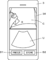
- the display control unit 35 Under the control of the terminal control unit 37, the display control unit 35 performs a predetermined process on the composite image M transmitted from the image synchronization unit 34, and as shown in FIG. 3, the terminal monitor 36 of the mobile information terminal 3 is subjected to predetermined processing. , The synchronized ultrasonic image U and the visual field image C are displayed together. Further, in the example shown in FIG. 3, in addition to the ultrasonic image U and the field image C, a freeze button B1 for freezing the ultrasonic image U and a save button B2 for saving the ultrasonic image U and the field image C Is displayed.
- freezing the ultrasonic image U means suspending the generation of the ultrasonic image U by stopping the transmission of ultrasonic waves from the vibrator array 21.
- the display control unit 35 can display the so-called user interface such as the freeze button B1 and the save button B2 on the terminal monitor 36 under the control of the terminal control unit 37.
- the terminal monitor 36 displays an ultrasonic image U, a field image C, and the like under the control of the display control unit 35.
- an LCD Liquid Crystal Display
- organic EL display Organic Electroluminescence Display
- Etc. including display devices.
- the input device 38 of the mobile information terminal 3 is for the operator to perform an input operation, and includes a touch sensor arranged so as to be superimposed on the terminal monitor 36.
- probe control information for controlling the ultrasonic probe 2 can be input by the operator via the input device 38.
- the probe control information input in this way is transmitted to the terminal side wireless communication unit 31 via the terminal control unit 37, and is wirelessly transmitted from the terminal side wireless communication unit 31 to the ultrasonic probe 2.
- the terminal control unit 37 controls each unit of the mobile information terminal 3 based on a control program or the like stored in advance. Further, although not shown, a terminal side storage unit is connected to the terminal control unit 37.
- the terminal-side storage unit stores a control program or the like of the mobile information terminal 3. Further, as the terminal side storage unit, for example, a flash memory, RAM, SD card, SSD or the like can be used. Further, although not shown, the mobile information terminal 3 has a built-in battery, and power is supplied from this battery to each circuit of the mobile information terminal 3.
- the terminal-side processor 39 having the terminal-side wireless communication unit 31, the image processing unit 32, the image synchronization unit 34, the display control unit 35, and the terminal control unit 37 is for causing the CPU and the CPU to perform various processes. Although it is composed of a control program, it may be configured by using FPGA, DSP, ASIC, GPU, or other IC, or may be configured by combining them. Further, the terminal-side wireless communication unit 31, the image processing unit 32, the image synchronization unit 34, the display control unit 35, and the terminal control unit 37 of the terminal-side processor 39 are partially or wholly integrated into one CPU or the like. It can also be configured.
- the external wireless communication unit 41 of the external device 4 includes an antenna for transmitting and receiving radio waves, and is transmitted by the probe-side wireless communication unit 24 of the ultrasonic probe 2 under the control of the external control unit 46.
- the transmission signal representing the received data before imaging and the transmission signal representing the field image C transmitted by the terminal-side wireless communication unit 31 of the mobile information terminal 3 are received via the antenna, and the received transmission signal is demolished. As a result, the received data before imaging and the field image C are output. Further, the external wireless communication unit 41 sends the received data before imaging to the image processing unit 42, and sends the visual field image C to the image synchronization unit 43.
- the image processing unit 42 rasterly converts the received data before imaging transmitted from the external wireless communication unit 41 into an image signal according to a normal television signal scanning method, and externally monitors the converted image signal.
- An ultrasonic image U is generated by performing various necessary image processing such as brightness correction, gradation correction, sharpness correction, image size correction, refresh rate correction, scanning frequency correction, and color correction according to the display format for 45. ..
- the image processing unit 42 sends the generated ultrasonic image U to the image synchronization unit 43.
- the image synchronization unit 43 of the external device 4 synchronizes the ultrasonic image U transmitted from the image processing unit 42 and the visual field image C transmitted from the external wireless communication unit 41 with each other, and the ultrasonic image U synchronized with each other. And the composite image M is generated based on the field image C.
- the image processing unit 42 of the external device 4 gives a time stamp indicating the time when the ultrasonic image U is generated to the ultrasonic image U, and the camera unit 33 of the mobile information terminal 3 generates the field image C.
- the image synchronization unit 43 considers the time stamp of the ultrasonic image U to represent the time when the ultrasonic image U was taken, and the field of view.
- the time stamp of the image C is regarded as representing the time when the field image C was taken, and by referring to the time stamps of the ultrasonic image U and the field image C, the ultrasonic image U and the ultrasonic image U taken at the same timing
- the field image C can be synchronized with each other.
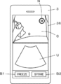
- the display control unit 44 Under the control of the external control unit 46, the display control unit 44 performs a predetermined process on the composite image M transmitted from the image synchronization unit 43, and causes the external monitor 45 of the external device 4 to perform a predetermined process as shown in FIG.
- the synchronized ultrasonic image U and the visual field image C are displayed together.
- the freeze button B1 and the save button B2 are displayed. In this way, the display control unit 44 can display the user interfaces such as the freeze button B1 and the save button B2 on the external monitor 45.
- the external monitor 45 displays the ultrasonic image U, the visual field image C, and the like under the control of the display control unit 44, and includes, for example, a display device such as an LCD or an organic EL display.
- the input device 47 of the external device 4 is for the operator to perform an input operation, and includes a touch sensor arranged so as to be superimposed on the external monitor 45.
- the external control unit 46 controls each unit of the external device 4 based on a control program or the like stored in advance.
- an external device side storage unit is connected to the external device 4.
- the storage unit on the external device side stores a control program or the like of the external device 4.
- a flash memory, RAM, SD card, SSD or the like can be used as the storage unit on the external device side.
- the external device 4 has a built-in battery, and power is supplied from this battery to each circuit of the external device 4.
- the external device side processor 48 having the external wireless communication unit 41, the image processing unit 42, the image synchronization unit 43, the display control unit 44, and the external control unit 46 is for causing the CPU and the CPU to perform various processes. Although it is composed of a control program, it may be configured by using FPGA, DSP, ASIC, GPU, or other IC, or may be configured by combining them. Further, the external wireless communication unit 41, the image processing unit 42, the image synchronization unit 43, the display control unit 44, and the external control unit 46 of the external device side processor 48 are partially or wholly integrated into one CPU or the like. It can also be configured.
- the operator contacts the ultrasonic probe 2 on the body surface of the subject, and under the control of the probe control unit 26, a plurality of oscillator arrays 21 follow the drive signals from the pulsar 51 of the transmission / reception circuit 22.
- An ultrasonic beam is transmitted from the oscillator into the subject.
- the ultrasonic echo based on the transmitted ultrasonic beam is received by each oscillator, the received signal which is an analog signal is output to the amplification unit 52 and amplified, and the AD conversion unit 53 performs AD conversion to acquire the received data. Will be done.
- a sound line signal is generated by performing reception focus processing on the received data by the beam former 54.
- the generated sound line signal is converted by the signal processing unit 23 into received data before imaging, which is a signal representing tomographic image information about the tissue in the subject.
- the signal processing unit 23 corrects the attenuation caused by the propagation distance of the sound line signal according to the depth of the position where the ultrasonic wave is reflected, and then performs the envelope detection process.
- the probe-side wireless communication unit 24 wirelessly transmits the generated sound line signal to the mobile information terminal 3 and the external device 4.
- the terminal-side wireless communication unit 31 of the mobile information terminal 3 receives the received data before imaging wirelessly transmitted from the ultrasonic probe 2 and sends the received received data before imaging to the image processing unit 32. ..
- the image processing unit 32 rasterly converts the received data before imaging transmitted from the terminal-side wireless communication unit 31 into an image signal according to a normal television signal scanning method, and the terminal receives the converted image signal.
- An ultrasonic image U is generated by performing various necessary image processing such as brightness correction, gradation correction, sharpness correction, image size correction, refresh rate correction, scanning frequency correction, and color correction according to the display format for the monitor 36. To do.
- the ultrasonic image U generated in this way is sent to the image synchronization unit 34.
- the camera unit 33 of the mobile information terminal 3 acquires the visual field image C obtained by capturing the scanning portion of the ultrasonic probe 2 in the subject under the control of the terminal control unit 37.
- the operator captures the field image C via the input device 38 of the portable information terminal 3 while pointing the photographing lens of the camera unit 33 toward the scanning portion of the ultrasonic probe 2 in the subject.
- Control information to that effect can be input.
- the control information input to the operator is input to the terminal control unit 37, and the terminal control unit 37 can control the camera unit 33 so as to capture the field image C according to the control information. ..
- the field-of-view image C thus acquired is sent to the terminal-side wireless communication unit 31 and the image synchronization unit 34.
- the image synchronization unit 34 When the image synchronization unit 34 receives the ultrasonic image U from the image processing unit 32 and the field image C from the camera unit 33, the received ultrasonic image U and the field image C are synchronized with each other and synchronized with each other. A composite image M in which the ultrasonic image U and the field image C are combined into one is generated.
- the image processing unit 32 gives a time stamp indicating the time when the ultrasonic image U is generated to the ultrasonic image U
- the camera unit 33 gives a time stamp indicating the time when the field image C is generated.
- the image synchronization unit 34 When given to the field image C, the image synchronization unit 34 considers the time stamp of the ultrasonic image U to represent the time when the ultrasonic image U was taken, and uses the time stamp of the field image C as the field image. Assuming that C represents the time when the image was taken, the ultrasonic image U and the field image C taken at the same timing are associated with each other by referring to the time stamps of the ultrasonic image U and the field image C. Can be done.
- the ultrasonic image U and the visual field image C synchronized with each other by the image synchronization unit 34 are sent to the display control unit 35 as a composite image M.
- the display control unit 35 sends the composite image M to the terminal monitor 36, and as shown in FIG. 3, the ultrasonic image U and the field image are displayed on the terminal monitor 36. Display with C.
- the visual field image C and the ultrasonic image U are displayed above and below the terminal monitor 36, respectively.
- the visual field image C depicts the state in which the ultrasonic probe 2 is in contact with the abdomen of the subject
- the ultrasonic image U depicts the internal tissue of the abdomen of the subject.
- the operator simultaneously obtains the field image C representing the scanning portion of the ultrasonic probe 2 in the subject and the ultrasonic image U corresponding to the field image C.
- the scanning location of the ultrasonic probe 2 in the subject and the tissue in the subject observed thereby can be easily associated and grasped.
- the field image C acquired by the camera unit 33 is wirelessly transmitted from the terminal side wireless communication unit 31 to the external device 4.
- the external wireless communication unit 41 of the external device 4 receives the received data before imaging wirelessly transmitted from the ultrasonic probe 2 and the field image C wirelessly transmitted from the mobile information terminal 3, and receives the received data before imaging.
- the received data is transmitted to the image processing unit 42, and the received field image C is transmitted to the image synchronization unit 43.
- the image processing unit 42 rasterly converts the received data before imaging transmitted from the external wireless communication unit 41 into an image signal according to a normal television signal scanning method, and externally monitors the converted image signal.
- An ultrasonic image U is generated by performing various necessary image processing such as brightness correction, gradation correction, sharpness correction, image size correction, refresh rate correction, scanning frequency correction, and color correction according to the display format for 45. ..
- the image processing unit 42 sends the generated ultrasonic image U to the image synchronization unit 43.
- the image synchronization unit 43 synchronizes the ultrasonic image U transmitted from the image processing unit 42 and the field image C transmitted from the external wireless communication unit 41 with each other, and the ultrasonic image U and the field image C synchronized with each other. Generates a composite image M in which For example, the image processing unit 42 of the external device 4 gives the ultrasonic image U a time stamp indicating the time when the ultrasonic image U was generated, and the camera unit 33 of the mobile information terminal 3 gives the field image C a field image C. When a time stamp representing the generated time is given to the field image C, the image synchronization unit 43 considers the time stamp of the ultrasonic image U to represent the time when the ultrasonic image U was taken.
- the time stamp of the field image C is regarded as representing the time when the field image C was taken, and by referring to the time stamps of the ultrasonic image U and the field image C, the ultrasonic image U taken at the same timing And the field image C can be synchronized with each other. At this time, the time on the portable information terminal 3 and the time on the external device 4 can be shared with each other.
- the time on the mobile information terminal 3 and the time on the external device 4 can be shared with each other. Specifically, for example, the time is shared based on either the mobile information terminal 3 or the external device 4. Can be done. Further, for example, when either the mobile information terminal 3 or the external device 4 is connected to the Internet, it is built in using a communication protocol such as NTP (Network Time Protocol) or NITZ (Network Identity and Time Zone). Clock time may be set.
- NTP Network Time Protocol
- NITZ Network Identity and Time Zone
- the ultrasonic image U and the visual field image C synchronized with each other by the image synchronization unit 43 are sent to the display control unit 44 as a composite image M.
- the display control unit 44 sends the composite image M to the external monitor 45, and as shown in FIG. 4, the ultrasonic image U and the visual field image are displayed on the external monitor 45. Display with C.
- the external device 4 is a portable terminal similar to the mobile information terminal 3, and the field image C and the ultrasonic image U are respectively above and below the terminal monitor 36 of the external device 4. Is displayed.
- the ultrasonic probe 2 is in contact with the visual field image C on the abdomen of the subject.
- the state is visualized, and the internal tissue of the abdomen of the subject is visualized on the ultrasonic image U.
- the field image C and the ultrasonic image U synchronized with each other are displayed on the terminal monitor 36 of the mobile information terminal 3 and the external monitor 45 of the external device 4, respectively, but the terminal monitor 36 and the external monitor 45 display each other. Displays the same field image C and ultrasonic image U almost at the same time. Therefore, for example, even when the external device 4 is located at a remote location with respect to the portable information terminal 3, the observer observing the external monitor 45 is the inspection site where the subject and the operator are located. The visual field image C and the ultrasonic image U captured in the above can be observed in almost real time.
- the input probe freeze is input.
- the instruction is input to the terminal control unit 37.
- the terminal control unit 37 controls the camera unit 33 so as to stop taking the field of view image C, triggered by the input of the probe freeze instruction.
- the terminal-side wireless communication unit 31 wirelessly transmits the probe freeze instruction sent from the terminal control unit 37 to the probe-side wireless communication unit 24 of the ultrasonic probe 2.
- the probe-side wireless communication unit 24 receives the probe freeze instruction wirelessly transmitted from the probe-side wireless communication unit 24, and inputs the received probe freeze instruction to the probe control unit 26.
- the probe control unit 26 controls the transmission / reception circuit 22 so as to stop the transmission of ultrasonic waves from the oscillator array 21 according to the probe freeze instruction, and the transmission of ultrasonic waves from the oscillator array 21 is stopped.
- the ultrasonic probe 2 transmits ultrasonic waves from the oscillator array 21 and the camera unit 33 of the mobile information terminal 3
- the shooting of the field image C is stopped.
- the display of the ultrasonic image U and the field image C is temporarily stopped on the terminal monitor 36 of the mobile information terminal 3, the transmission of ultrasonic waves from the transducer array 21 and the shooting of the field image C by the camera unit 33 are stopped.
- the ultrasonic image U and the visual field image C immediately before the image is displayed.
- the display of the ultrasonic image U and the field image C is temporarily stopped as in the terminal monitor 36 of the mobile information terminal 3, and the ultrasonic waves are transmitted from the transducer array 21 and transmitted.
- the ultrasonic image U and the field image C immediately before the shooting of the field image C by the camera unit 33 is stopped are displayed.
- an observer observing the ultrasonic image U and the visual field image C displayed on the external monitor 45 inputs a probe freeze instruction indicating that the ultrasonic image U is frozen via the input device 47 of the external device 4. Then, the input probe freeze instruction is sent to the external wireless communication unit 41 via the external control unit 46.
- the external wireless communication unit 41 wirelessly transmits a probe freeze instruction to the terminal side wireless communication unit 31 of the mobile information terminal 3.
- the terminal-side wireless communication unit 31 wirelessly transmits the probe freeze instruction wirelessly transmitted by the external wireless communication unit 41 of the external device 4 to the probe-side wireless communication unit 24 of the ultrasonic probe 2, and terminal-controls the probe freeze instruction. Input to unit 37.
- the probe-side wireless communication unit 24 of the ultrasonic probe 2 receives the probe freeze instruction wirelessly transmitted by the terminal-side wireless communication unit 31 of the mobile information terminal 3, and inputs the received probe freeze instruction to the probe control unit 26.
- the probe control unit 26 controls the transmission / reception circuit 22 so as to stop the transmission of ultrasonic waves from the oscillator array 21 in accordance with the probe freeze instruction.
- the terminal control unit 37 controls the camera unit 33 so as to stop taking the visual field image C by using the input of the probe freeze instruction as a trigger.
- the probe freeze instruction is input via the input device 47 of the external device 4
- the ultrasonic probe 2 transmits ultrasonic waves from the vibrator array 21 and the camera unit 33 of the portable information terminal 3 transmits the ultrasonic waves.
- Shooting of the field image C is stopped.
- the display of the ultrasonic image U and the field image C is temporarily stopped on the terminal monitor 36 of the mobile information terminal 3, the transmission of ultrasonic waves from the transducer array 21 and the shooting of the field image C by the camera unit 33 are stopped.
- the ultrasonic image U and the visual field image C immediately before the image is displayed.
- the display of the ultrasonic image U and the field image C is temporarily stopped as in the terminal monitor 36 of the mobile information terminal 3, and the ultrasonic waves are transmitted from the transducer array 21 and transmitted.
- the ultrasonic image U and the field image C immediately before the shooting of the field image C by the camera unit 33 is stopped are displayed.
- an ultrasonic image is taken in a remote place outside the hospital, such as at home nursing
- the operator who operates the ultrasonic probe to take the ultrasonic image and the photographed ultrasonic image are observed. Observers such as doctors making the diagnosis may differ from each other.
- the operator usually needs to operate the ultrasonic probe while checking the obtained ultrasonic image by himself / herself to take an ultrasonic image of a target site in the subject.
- the skill level of the operator is low, it may be difficult for the operator to determine whether or not the target site of the subject can be accurately observed.
- an operator with a low skill level may not be able to operate the ultrasonic probe by using an appropriate technique, and an ultrasonic image with low image quality may be obtained.
- the observer located at a remote location with respect to the subject and the operator will confirm the ultrasonic image taken by the operator of the ultrasonic diagnostic apparatus to make a diagnosis, but the operator will perform the ultrasonic image. Since it is not possible to grasp how to shoot the ultrasound image, it is accurate whether or not the captured ultrasound image was taken by an appropriate procedure, especially when the ultrasonic image was taken by an operator with low skill. It was sometimes difficult to judge.
- the same field image C and ultrasonic image U are displayed on the terminal monitor 36 and the external monitor 45 at almost the same time. Therefore, for example, the external device 4 Even when is located at a remote location with respect to the mobile information terminal 3, the observer observing the external monitor 45 can see the field image C taken at the inspection site where the subject and the operator are located. And the ultrasonic image U can be observed in almost real time. As a result, for example, a highly skilled observer can give advice to the operator in real time, so that even if the operator located at a remote location has a low skill level, the observer can be given advice in real time. An appropriate ultrasonic image U can be obtained, and the accuracy of ultrasonic diagnosis can be improved.
- the ultrasonic system 1 corresponds to a field image C showing a state in which a highly skilled operator operates the ultrasonic probe 2 and a field image C thereof. It is also possible to have the operator confirm the appropriate ultrasonic image U by an observer who is located at a remote location and has a low skill level. As described above, the ultrasonic system 1 according to the first embodiment of the present invention is very useful from the viewpoint of education.
- an observer observing the ultrasonic image U and the visual field image C displayed on the external monitor 45 passes through the input device 47 of the external device 4.
- the transmission of ultrasonic waves from the transducer array 21 of the ultrasonic probe 2 is stopped, and the acquisition of the field image C by the camera unit 33 of the mobile information terminal 3 is stopped, and the mobile information
- the display of the ultrasonic image U and the visual field image C is paused at the same time on the terminal monitor 36 of the terminal 3 and the external monitor 45 of the external device 4.
- the probe freeze instruction input by the observer observing the ultrasonic image U and the field image C displayed on the external monitor 45 via the input device 47 of the external device 4 is sent from the external wireless communication unit 41 to the mobile information terminal.
- wireless transmission is performed to the probe-side wireless communication unit 24 of the ultrasonic probe 2 via the terminal-side wireless communication unit 31 of 3, the method of wirelessly transmitting the probe freeze instruction is not limited to this.
- the external wireless communication unit 41 can wirelessly transmit the probe freeze instruction to both the probe-side wireless communication unit 24 of the ultrasonic probe 2 and the terminal-side wireless communication unit 31 of the mobile information terminal 3.
- the probe freeze instruction received by the probe side wireless communication unit 24 of the ultrasonic probe 2 is input to the probe control unit 26, and the probe control unit 26 is based on the input probe freeze instruction and the oscillator array.
- the transmission / reception circuit 22 is controlled so as to stop the transmission of ultrasonic waves from 21.
- the probe freeze instruction received by the terminal-side wireless communication unit 31 of the mobile information terminal 3 is input to the terminal control unit 37.
- the terminal control unit 37 controls the display control unit 35 so as to suspend the display of the ultrasonic image U and the field image C on the terminal monitor 36 by using the input of the probe freeze instruction as a trigger, and the terminal control unit 37 controls the display control unit 35 of the field image C.
- the camera unit 33 is controlled so as to stop shooting. As a result, the transmission of ultrasonic waves from the transducer array 21 and the acquisition of the field image C by the camera unit 33 are stopped, and the ultrasonic images are displayed on the terminal monitor 36 of the mobile information terminal 3 and the external monitor 45 of the external device 4.
- the display of U and the field image C is paused at the same time.
- the external wireless communication unit 41 can wirelessly transmit the probe freeze instruction only to the probe side wireless communication unit 24 of the ultrasonic probe 2.
- the probe freeze instruction received by the probe-side wireless communication unit 24 is input to the probe control unit 26 and wirelessly transmitted to the terminal-side wireless communication unit 31 of the mobile information terminal 3.
- the probe control unit 26 controls the transmission / reception circuit 22 so as to stop the transmission of ultrasonic waves from the vibrator array 21 according to the input probe freeze instruction.
- the terminal-side wireless communication unit 31 of the mobile information terminal 3 receives the probe freeze instruction wirelessly transmitted by the probe-side wireless communication unit 24 of the ultrasonic probe 2, and transmits the received probe freeze instruction to the terminal control unit 37. input.
- the terminal control unit 37 controls the display control unit 35 so as to suspend the display of the ultrasonic image U and the visual field image C on the terminal monitor 36 triggered by the input of the probe freeze instruction. Further, the terminal control unit 37 controls the camera unit 33 so as to stop taking the visual field image C by using the input of the probe freeze instruction as a trigger.
- the image processing unit 32 of the mobile information terminal 3 and the image processing unit 42 of the external device 4 each give a time stamp to the generated ultrasonic image U.
- the signal processing unit 23 of the ultrasonic probe 2 performed the envelope detection process. It is also possible to add a time stamp to the signal. In this case, for example, the time in the ultrasonic probe 2 and the time in the mobile information terminal 3 are shared with each other, so that the time is generated by the image processing unit 32 of the mobile information terminal 3 based on the time stamped signal.
- the ultrasonic image U and the field image C generated by the camera unit 33 are synchronized with each other, and the ultrasonic image U generated by the image processing unit 42 of the external device 4 and the field image generated by the camera unit 33 are synchronized with each other.
- C can be synchronized with each other.
- the time on the ultrasonic probe 2 and the time on the mobile information terminal 3 can be shared based on, for example, either the ultrasonic probe 2 or the mobile information terminal 3. Further, for example, when either one of the ultrasonic probe 2 and the mobile information terminal 3 is connected to the Internet, the time of the built-in clock may be set using a communication protocol such as NTP or NITZ.
- the method of synchronizing the ultrasonic image U and the visual field image C with each other is not limited to the method using the time stamp described above.
- the imaging timing of the ultrasonic image U by the ultrasonic probe 2 and the imaging timing of the field image C by the camera unit 33 of the mobile information terminal 3 are synchronized.
- the image synchronization unit 34 of the mobile information terminal 3 and The image synchronization unit 43 of the external device 4 considers that the ultrasonic image U and the field image C have been captured at the same timing, and can synchronize the ultrasonic image U and the field image C with each other.
- the image synchronization unit 34 of the mobile information terminal 3 generates a composite image M in which the ultrasonic image U and the visual field image C synchronized with each other are combined into one, and the generated composite image M is displayed in the display control unit 35.
- the ultrasonic image U and the field image C synchronized with each other can be transmitted to the display control unit 35, respectively.
- the display control unit 35 performs predetermined processing on the ultrasonic image U and the visual field image C transmitted from the image synchronization unit 34, and synchronizes with each other on the terminal monitor 36 as shown in FIG.
- the ultrasonic image U and the visual field image C are displayed together. Therefore, the operator can simultaneously confirm the position of the ultrasonic probe 2 and the state of the tissue in the subject corresponding thereto.
- the image synchronization unit 43 of the external device 4 can send the ultrasonic image U and the visual field image C synchronized with each other to the display control unit 44, respectively, instead of generating the composite image M. Also in this case, since the ultrasonic image U and the visual field image C synchronized with each other are simultaneously displayed on the external monitor 45, the observer looking at the external monitor 45 is positioned with the subject and the operator. It is possible to observe the visual field image C and the ultrasonic image U taken at the inspection site in almost real time.
- the ultrasonic probe 2 and the mobile information terminal 3 are connected to each other by wireless communication, for example, instead of the connection by wireless communication, they can be connected to each other by wired communication.
- the external device 4 is a portable thin computer called a so-called smartphone or tablet like the mobile information terminal 3, but the external device 4 is not limited to this.
- a so-called notebook type personal computer, a stationary type personal computer, or the like can be used as the external device 4.
- a second external device having a monitor is installed in the vicinity of the site where the subject is inspected by the operator, and the second external device is used as the ultrasonic probe 2 and the portable information terminal 3. Can also be connected to display the ultrasonic image U and the field image C on the monitor of the second external device.
- the operator can more clearly confirm the ultrasonic image U and the visual field image C, so that the scanning location of the ultrasonic probe 2 in the subject And, the tissue in the observed subject can be more clearly associated and grasped.
- the mobile information terminal 3 is exemplified as a portable thin computer called a so-called smartphone or tablet, but the portable information terminal is not limited to this.
- a terminal device that can be worn on the operator's head can also be used as the mobile information terminal 3.
- a terminal monitor 36 is arranged so as to face the operator's eyes when worn on the head, and a field image C representing a field of view in front of the operator is captured by the camera unit 33. Will be done.
- the operator can indirectly confirm the front field of view by checking the field of view image C displayed on the terminal monitor 36 instead of directly checking the front field of view.
- the operator does not need to hold the mobile information terminal 3 in his / her hand. Therefore, for example, the operator has one hand. It is possible to perform a wider variety of tests, such as performing a procedure of inserting a so-called puncture needle into a subject using the other hand while operating the ultrasonic probe 2 using the ultrasonic probe 2.
- the transmission / reception circuit 22 has a beam former 54 together with the amplification unit 52 and the AD conversion unit 53, but the beam former 54 is not inside the transmission / reception circuit 22 but the transmission / reception circuit 22. It may be arranged between the signal processing unit 23 and the signal processing unit 23. In this case, the beam former 54 can also be configured by the probe-side processor 27.
- the probe freeze instruction is input via the input device 38 of the mobile information terminal 3 and the probe freeze instruction is input via the input device 47 of the external device 4.
- the transmission of ultrasonic waves from the transducer array 21 of the ultrasonic probe 2 and the acquisition of the field image C by the camera unit 33 of the mobile information terminal 3 are stopped.
- the terminal monitor 36 of the mobile information terminal 3 is stopped.
- the instruction information indicating that the probe freeze instruction is input from the input device 38 of the mobile information terminal 3 or the probe freeze instruction is input from the input device 47 of the external device 4.
- Source information can be displayed.
- a probe freeze instruction is input via the input device 47 of the external device 4 by an observer observing the ultrasonic image U and the field image C displayed on the external monitor 45.
- a message K indicating that a probe freeze instruction has been input can be displayed via the input device 47 of the external device 4.
- the message K "remote freeze in progress" is displayed on the terminal monitor 36.
- the external monitor 45 also displays the same message K as the message K displayed on the terminal monitor 36.
- a probe freeze instruction is input by an operator of the ultrasonic probe 2 and the mobile information terminal 3 via the input device 38 of the mobile information terminal 3, although not shown, the terminal monitor 36 of the mobile information terminal 3 is not shown.
- a message K indicating that the probe freeze instruction has been input via the input device 38 of the mobile information terminal 3 such as “during local freeze” is displayed.
- FIG. 6 shows.
- the terminal monitor 36 of the mobile information terminal 3 can display the stop icon N indicating that the probe freeze instruction has been input via the input device 47 of the external device 4.
- the external monitor 45 also displays the same stop icon N as the stop icon N displayed on the terminal monitor 36.
- the terminal monitor 36 of the mobile information terminal 3 is not shown.
- a stop icon different from the stop icon N displayed when the probe freeze instruction is input via the input device 47 of the external device 4 is displayed.
- Examples of such a stop icon include a stop icon having a shape, size, color, or the like different from the stop icon N displayed when a probe freeze instruction is input via the input device 47 of the external device 4. Be done.
- FIG. 7 shows.
- the terminal monitor 36 of the mobile information terminal 3 can display the frame line H indicating that the probe freeze instruction has been input via the input device 47 of the external device 4.
- the external monitor 45 also displays the same frame line H as the frame line H displayed on the terminal monitor 36.
- the terminal monitor 36 of the mobile information terminal 3 is not shown.
- a frame line different from the frame line displayed when the probe freeze instruction is input via the input device 47 of the external device 4 is displayed.
- a border for example, a border having a shape, size, thickness, color, or the like different from the border displayed when the probe freeze instruction is input via the input device 47 of the external device 4. Can be mentioned.
- the probe freeze instruction is input from the input device 38 of the mobile information terminal 3 or the input device 47 of the external device 4.
- the operator of the ultrasonic probe 2 and the mobile information terminal 3 and the observer looking at the external monitor 45 can be viewed from either the mobile information terminal 3 side or the external device 4 side. It is possible to easily grasp whether the probe freeze instruction has been input. In particular, even when the display of the ultrasonic image U and the field image C is suddenly paused on the terminal monitor 36 of the mobile information terminal 3 by inputting the probe freeze instruction via the input device 47 of the external device 4.
- the operator of the ultrasonic probe 2 and the mobile information terminal 3 can easily grasp that the probe freeze instruction has been input via the input device 47 of the external device 4, and for example, the display of the ultrasonic probe is temporarily stopped. Operations such as saving the image U and the field image C can be performed without any confusion.
- the transmission of ultrasonic waves from the transducer array 21 and the acquisition of the field image C by the camera unit 33 are stopped, and the display of the ultrasonic image U and the field image C on the terminal monitor 36 and the external monitor 45 is temporarily stopped.
- the transmission of ultrasonic waves from the transducer array 21 is stopped by the input operation of the operator via the input device 38 of the mobile information terminal 3 and the input operation of the observer via the input device 47 of the external device 4.
- the stop of shooting the field image C by the camera unit 33 is released, and the ultrasonic image U and the field image C can be continuously displayed again on the terminal monitor 36 and the external monitor 45.
- the freeze button displayed on the terminal monitor 36 is displayed.
- the transmission of ultrasonic waves from the transducer array 21 and the camera unit 33 the transmission of ultrasonic waves from the transducer array 21 and the camera unit 33.
- the shooting of the field image C can be stopped, and the display of the ultrasonic image U and the field image C on the terminal monitor 36 and the external monitor 45 can be temporarily stopped.
- the freeze button B1 displayed on the terminal monitor 36 or the freeze displayed on the external monitor 45 is displayed.
- the button B1 is touched again, the stop of the transmission of ultrasonic waves from the transducer array 21 and the stop of the shooting of the field image C by the camera unit 33 are released, and the terminal monitor 36 and the external monitor 45 are superposed.
- the ultrasonic image U and the visual field image C can be continuously displayed again.
- the freeze button B1 displayed on the terminal monitor 36 and the freeze button B1 displayed on the external monitor 45 stop the transmission of ultrasonic waves from the oscillator array 21 and the field image C by the camera unit 33. It can be used as a release button to release the stop of shooting.
- the probe freeze instruction such as the message K shown in FIG. 5 and the stop icon N shown in FIG. 6 is the input device 38 of the mobile information terminal 3 and the input device 47 of the external device 4.
- the instruction information source information indicating which of the above is input
- the instruction information source information displayed on the terminal monitor 36 is touched by the operator, or the external monitor 45 is used.
- the transmission of ultrasonic waves from the transducer array 21 and the stoppage of the capture of the visual field image C by the camera unit 33 are released, and the terminal monitor 36 is released. And the ultrasonic image U and the field image C can be continuously displayed again on the external monitor 45.
- external input information such as a cursor A that can be moved by an observer's input operation via the input device 47 of the external device 4 is transmitted to the external monitor 45 of the external device 4 and the mobile information terminal. It can be displayed on the terminal monitor 36 of 3 at the same time.
- the terminal monitor 36 of the mobile information terminal 3 is moved.
- the displayed cursor A is also moved in the same manner. Thereby, for example, more detailed information sharing can be performed between the operator of the ultrasonic probe 2 and the portable information terminal 3A and the observer located in the vicinity of the external device 4A.
- a highly skilled observer observing the ultrasonic image U and the field image C on the external monitor 45 of the external device 4A may contact the less skilled operator of the ultrasonic probe 2 and the portable information terminal 3A. It is possible to easily support the inspection performed by the operator, such as indicating the position where the ultrasonic probe 2 should be scanned by using the cursor A.
- the cursor A that can be moved by the input operation of the operator via the input device 38 of the mobile information terminal 3 can be simultaneously displayed on the terminal monitor 36 of the mobile information terminal 3 and the external monitor 45 of the external device 4. it can.
- a highly skilled operator can more easily and in detail educate a less skilled observer located in the vicinity of the external device 4A on ultrasonic diagnosis.
- the shape of the cursor A is not limited to the arrow shape, and can have any shape such as a circular shape or a polygonal shape.
- FIG. 9 shows the configuration of the mobile information terminal 3A in the modified example of the first embodiment of the present invention.
- a microphone 61 and a speaker 62 are added, a terminal control unit 37A is provided instead of the terminal control unit 37, and a terminal side processor is provided instead of the terminal side processor 39. It is equipped with a 39A.
- the microphone 61 and the speaker 62 are connected to the terminal side wireless communication unit 31.
- FIG. 10 shows the configuration of the external device 4A in the modified example of the first embodiment of the present invention.
- a microphone 63 and a speaker 64 are added, an external control unit 46A is provided instead of the external control unit 46, and an external device side processor is provided instead of the external device side processor 48. It is equipped with 48A.
- the microphone 63 and the speaker 64 are connected to the external wireless communication unit 41.
- voice data is transmitted and received bidirectionally between the mobile information terminal 3A and the external device 4A.
- the emitted voice is input to the microphone 61 of the mobile information terminal 3A, and the voice data is generated by the microphone 61. Will be generated.
- the generated voice data is wirelessly transmitted from the terminal-side wireless communication unit 31 to the external device 4A.
- the external wireless communication unit 41 of the external device 4A receives the voice data wirelessly transmitted from the mobile information terminal 3A, and transmits the received voice data to the speaker 64.
- the speaker 64 reproduces the voice emitted by the operator of the ultrasonic probe 2 and the portable information terminal 3A based on the voice data received from the external wireless communication unit 41.
- the emitted sound is the external device 4A. It is input to the microphone 63, and audio data is generated by the microphone 63.
- the generated voice data is wirelessly transmitted from the external wireless communication unit 41 to the mobile information terminal 3A.
- the terminal-side wireless communication unit 31 of the mobile information terminal 3A receives the voice data wirelessly transmitted from the external device 4A, and transmits the received voice data to the speaker 62.
- the speaker 62 reproduces the voice emitted by the observer located in the vicinity of the external device 4 based on the voice data received from the terminal-side wireless communication unit 31.
- the voice of the operator input to the microphone 61 of the mobile information terminal 3A can be used as the input operation of the operator.
- the terminal control unit 37A acquires instruction information by analyzing the audio data generated based on the operator's voice by the microphone 61, and the camera unit 33 captures the field image C according to the acquired instruction information. It is possible to control each part of the mobile information terminal 3A, such as starting and stopping shooting.
- the ultrasonic probe 2 can be controlled based on the voice data analyzed by the terminal control unit 37A.
- the voice data analyzed by the terminal control unit 37A is wirelessly transmitted from the terminal side wireless communication unit 31 to the ultrasonic probe 2 as input information from the operator, and is transmitted via the probe side wireless communication unit 24.
- the probe control unit 26 controls each part of the ultrasonic probe 2 based on the input information, for example, transmission start and transmission stop of ultrasonic waves by the vibrator array 21, shooting start and shooting stop of the visual field image C by the camera unit 33, and the like. can do.
- the observer's voice input to the microphone 63 of the external device 4A can be used as the observer's input operation.
- the external control unit 46A acquires instruction information by analyzing the voice data generated based on the observer's voice by the microphone 63, and the camera unit 33 of the portable information terminal 3A follows the acquired instruction information. Control of each part of the portable information terminal 3A such as start and stop of photographing of the field image C, and control of each part of the ultrasonic probe 2 such as start and stop of transmission of ultrasonic waves by the transducer array 21 of the ultrasonic probe 2. You can also do it.
- the ultrasonic probe 2 generates the received data before imaging in which the sound line signal is subjected to the envelope detection processing, and the generated received data before imaging is the mobile information terminal 3 and the mobile information terminal 3.
- the ultrasonic image U is wirelessly transmitted to the external device 4
- the ultrasonic image U is generated by the ultrasonic probe 2, and the generated ultrasonic image U can be wirelessly transmitted to the portable information terminal 3 and the external device 4.
- FIG. 11 shows the configuration of the ultrasonic system 1B according to the second embodiment of the present invention.
- the ultrasonic system 1 is provided with an ultrasonic probe 2A instead of the ultrasonic probe 2 and a portable information terminal 3B instead of the portable information terminal 3.
- An external device 4B is provided instead of the external device 4.
- the image processing unit 71 is added to the ultrasonic probe 2 in the first embodiment, the probe control unit 26B is provided instead of the probe control unit 26, and the probe side processor is provided instead of the probe side processor 27. It is equipped with 27B.
- the image processing unit 71 is connected to the signal processing unit 23.
- the signal processing unit 23 and the image processing unit 71 constitute an ultrasonic image generation unit.
- the probe side wireless communication unit 24 and the probe control unit 26B are connected to the image processing unit 71.
- the image processing unit 32 is removed, the terminal control unit 37B is provided instead of the terminal control unit 37, and the terminal side processor is provided instead of the terminal side processor 39. It is equipped with 39B.
- the image synchronization unit 34 and the camera unit 33 are connected to the terminal side wireless communication unit 31.
- the external device 4B of the first embodiment the image processing unit 42 is removed, the external control unit 46B is provided in place of the external control unit 46, and the external device side processor 48 is replaced by the external device side processor 48. It is equipped with 48B.
- the image processing unit 71 of the ultrasonic probe 2B rasterly converts the signal subjected to the envelope detection processing by the signal processing unit 23 into an image signal according to a normal television signal scanning method, and the converted image signal is subjected to raster conversion. , Brightness correction, gradation correction, sharpness correction, image size correction, refresh rate correction, scanning frequency correction, color correction, and other necessary image processing to display for the terminal monitor 36 of the mobile information terminal 3B. An ultrasonic image U according to the format and an ultrasonic image U according to the format for the external monitor 45 of the external device 4B are generated.
- the image processing unit 71 wirelessly transmits an ultrasonic image U according to the display format for the terminal monitor 36 of the mobile information terminal 3B from the probe side wireless communication unit 24 to the mobile information terminal 3B, and is used for the external monitor 45 of the external device 4B.
- the ultrasonic image U according to the above format is wirelessly transmitted from the probe side wireless communication unit 24 to the external device 4B.
- the terminal-side wireless communication unit 31 of the mobile information terminal 3B receives the ultrasonic image U wirelessly transmitted from the ultrasonic probe 2B, and sends the received ultrasonic image U to the image synchronization unit 34.
- the image synchronization unit 34 synchronizes the ultrasonic image U transmitted from the terminal-side wireless communication unit 31 and the field image C generated by the camera unit 33 with each other, and the ultrasonic image U and the field image C synchronized with each other.
- a composite image M is generated based on.
- the image processing unit 71 of the ultrasonic probe 2B gives a time stamp indicating the time when the ultrasonic image U is generated to the ultrasonic image U
- the camera unit 33 of the mobile information terminal 3B gives the field image C.
- the image synchronization unit 34 determines the ultrasonic image U based on the ultrasonic image U and the time stamp given to the field image C. And the field image C can be synchronized with each other.
- the display control unit 35 After performing a predetermined process on the composite image M generated by the image synchronization unit 34, the display control unit 35 sends the composite image M to the terminal monitor 36, and as shown in FIG. 3, the terminal monitor 36 , The ultrasonic image U and the field image C synchronized with each other are displayed together.
- the external wireless communication unit 41 of the external device 4B receives the ultrasonic image U wirelessly transmitted from the ultrasonic probe 2B and the field image C wirelessly transmitted from the mobile information terminal 3B, and receives the received ultrasonic image U and the field image. C is sent to the image synchronization unit 43.
- the image synchronization unit 43 synchronizes the ultrasonic image U and the visual field image C transmitted from the external wireless communication unit 41 with each other, and generates a composite image M based on the ultrasonic image U and the visual field image C synchronized with each other. To do.
- the display control unit 44 sends the composite image M to the external monitor 45, and as shown in FIG. 4, the external monitor 45 ,
- the ultrasonic image U and the visual field image C synchronized with each other are displayed together.
- the portable information terminal 3 has the image processing unit 32.
- the same field image C and ultrasonic image U are displayed on the terminal monitor 36 and the external monitor 45 substantially at the same time as in the ultrasonic system 1 of the first embodiment in which the external device 4 is provided with the image processing unit 42. .. Therefore, for example, the observer who observes the field image C and the ultrasonic image U by the external device 4B arranged at a remote location can give advice to the operator of the ultrasonic probe 2B and the portable information terminal 3B. Therefore, an appropriate ultrasonic image U can be obtained, and the accuracy of ultrasonic diagnosis can be improved.
- the ultrasonic image U and the visual field image C displayed on the external monitor 45 are observed in the same manner as the ultrasonic system 1 of the first embodiment.
- the observer inputs the probe freeze instruction via the input device 47 of the external device 4B
- the transmission of ultrasonic waves from the transducer array 21 of the ultrasonic probe 2 is stopped and the camera unit 33 of the portable information terminal 3B is stopped.
- the imaging of the field image C is stopped, and the display of the ultrasonic image U and the field image C is paused at the same time on the terminal monitor 36 of the mobile information terminal 3B and the external monitor 45 of the external device 4B.
- the portable information terminal 3 is provided with the image processing unit 32 and the external device 4 is provided with the image processing unit 42.
- the ultrasonic probe 2B is provided with the image processing unit 71
- the portable information terminal 3B and the external device 4B do not need to have the image processing units 32 and 42, respectively, and the portable information terminal 3B and the external device 4B do not need to have the image processing units 32 and 42, respectively.
- the internal configuration of the external device 4B is simplified as compared with the internal configuration of the portable information terminal 3 and the external device 4 in the ultrasonic system 1 of the first embodiment. Therefore, according to the ultrasonic system 1B according to the second embodiment, it is possible to reduce the power consumption and the calculation load of the portable information terminal 3B and the external device 4B as compared with the ultrasonic system 1 of the first embodiment. Is.
- the ultrasonic image U and the visual field image C are synchronized in the mobile information terminal 3 and the external device 4, respectively.
- the ultrasonic image U and the visual field image C are synchronized only in the mobile information terminal 3. It can also be synchronized.
- FIG. 12 shows the configuration of the ultrasonic system 1C according to the third embodiment of the present invention.
- the ultrasonic system 1 includes an ultrasonic probe 2C having the same internal configuration as the ultrasonic probe 2 in the ultrasonic system 1 of the first embodiment shown in FIG. 1, and is provided with a portable information terminal instead of the portable information terminal 3.
- the 3C is provided, and the external device 4C is provided instead of the external device 4.
- the ultrasonic probe 2C is connected only to the mobile information terminal 3C by wireless communication, and the external device 4C is connected only to the mobile information terminal 3C by wireless communication.
- the mobile information terminal 3C is the mobile information terminal 3 according to the first embodiment, in which the terminal control unit 37C is provided instead of the terminal control unit 37, and the terminal side processor 39C is provided instead of the terminal side processor 39. ..
- the image synchronization unit 34 is connected to the terminal side wireless communication unit 31. Further, the camera unit 33 is connected to the image synchronization unit 34.
- the image processing unit 42 and the image synchronization unit 43 are removed, and the external device 4C is provided with the external control unit 46C instead of the external control unit 46, instead of the external device side processor 48. Is provided with an external device side processor 48C.
- the display control unit 44 is connected to the external wireless communication unit 41.
- the probe-side wireless communication unit 24 of the ultrasonic probe 2C wirelessly transmits the received data before imaging, which has been subjected to the envelope detection process by the signal processing unit 23, only to the mobile information terminal 3C.
- the terminal-side wireless communication unit 31 of the mobile information terminal 3C receives the received data before imaging wirelessly transmitted from the ultrasonic probe 2C, and sends the received received data before imaging to the image processing unit 32.
- the image processing unit 32 rasterly converts the received data before imaging transmitted from the terminal-side wireless communication unit 31 into an image signal according to a normal television signal scanning method, and brightens the converted image signal.
- the display format for the terminal monitor 36 of the mobile information terminal 3B by performing various necessary image processing such as correction, gradation correction, sharpness correction, image size correction, refresh rate correction, scanning frequency correction and color correction.
- the ultrasonic image U and the ultrasonic image U according to the format for the external monitor 45 of the external device 4B are generated.
- the image processing unit 32 sends an ultrasonic image U according to the display format for the terminal monitor 36 of the portable information terminal 3B and an ultrasonic image U according to the format for the external monitor 45 of the external device 4B to the image synchronization unit 34.
- the camera unit 33 acquires a visual field image C that captures the scanning portion of the ultrasonic probe 2C in the subject, and sends the acquired visual field image C to the image synchronization unit 34.
- the image synchronization unit 34 synchronizes the ultrasonic image U transmitted from the image processing unit 32 and the field image C transmitted from the camera unit 33 with each other. More specifically, the image synchronization unit 34 synchronizes the ultrasonic image U and the field image C according to the display format for the terminal monitor 36 of the mobile information terminal 3B with each other to generate a composite image M, and further, an external device.
- the ultrasonic image U and the field image C according to the display format for the external monitor 45 of 4C are synchronized with each other to generate the composite image M.
- the image synchronization unit 34 sends a composite image M generated based on the ultrasonic image U and the visual field image C according to the display format for the terminal monitor 36 of the portable information terminal 3B synchronized with each other to the display control unit 35. To do.
- the display control unit 35 performs a predetermined process on the composite image M sent from the image synchronization unit 34, then sends the composite image M to the terminal monitor 36, and as shown in FIG. 3, the terminal monitor 36 , The ultrasonic image U and the field image C synchronized with each other are displayed together. Further, the image synchronization unit 34 transmits the ultrasonic image U according to the display format for the external monitor 45 of the external device 4C and the composite image M generated based on the field image C to the terminal side wireless communication unit 31.
- the terminal-side wireless communication unit 31 wirelessly transmits the composite image M transmitted from the image synchronization unit 34 to the external device 4C.
- the external wireless communication unit 41 of the external device 4C receives the composite image M wirelessly transmitted from the mobile information terminal 3C, and sends the received composite image M to the display control unit 44.
- the display control unit 44 performs a predetermined process on the composite image M sent from the external wireless communication unit 41, then sends the composite image M to the external monitor 45, and as shown in FIG. 4, the external monitor 45 In, the ultrasonic image U and the visual field image C synchronized with each other are displayed together.
- the probe freeze instruction input via the input device 47 of the external device 4C by the observer observing the ultrasonic image U and the field image C displayed on the external monitor 45 is sent to the outside via the external control unit 46C. It is sent to the wireless communication unit 41.
- the external wireless communication unit 41 wirelessly transmits the probe freeze instruction only to the terminal-side wireless communication unit 31 of the mobile information terminal 3C.
- the terminal-side wireless communication unit 31 inputs the probe freeze instruction wirelessly transmitted from the external wireless communication unit 41 of the external device 4C to the terminal control unit 37C and wirelessly transmits the probe freeze instruction to the probe control unit 26 of the ultrasonic probe 2C.
- the terminal control unit 37C of the mobile information terminal 3C controls the camera unit 33 so as to stop the generation of the visual field image C when the probe freeze instruction is input as a trigger. Further, the probe-side wireless communication unit 24 of the ultrasonic probe 2C inputs a probe freeze instruction wirelessly transmitted by the terminal-side wireless communication unit 31 of the mobile information terminal 3C to the probe control unit 26. The probe control unit 26 controls the transmission / reception circuit 22 so as to stop the transmission of ultrasonic waves from the vibrator array 21 according to the input probe freeze instruction.
- the ultrasonic system 1C even when the image processing unit 32 and the image synchronization unit 34 are provided only in the mobile information terminal 3C, the mobile information terminal 3 Is provided with the image processing unit 32 and the external device 4 is provided with the image processing unit 42. Similar to the ultrasonic system 1 of the first embodiment, the terminal monitor 36 and the external monitor 45 are substantially the same field image C and ultrasonic image at the same time. U is displayed. Therefore, for example, the observer who observes the field image C and the ultrasonic image U by the external device 4C arranged at a remote location can give advice to the operator of the ultrasonic probe 2C and the portable information terminal 3C. Therefore, an appropriate ultrasonic image U can be obtained, and the accuracy of ultrasonic diagnosis can be improved.
- the ultrasonic image U and the visual field image C displayed on the external monitor 45 are observed in the same manner as the ultrasonic system 1 of the first embodiment.
- the observer inputs the probe freeze instruction via the input device 47 of the external device 4C
- the transmission of ultrasonic waves from the transducer array 21 of the ultrasonic probe 2 is stopped, and the camera unit 33 of the portable information terminal 3C
- the imaging of the field image C is stopped, and the display of the ultrasonic image U and the field image C is paused at the same time on the terminal monitor 36 of the mobile information terminal 3C and the external monitor 45 of the external device 4C.
- the external device 4 is provided with an image processing unit 42 and an image synchronization unit 43, but the ultrasonic system 1C according to the third embodiment is portable. Since the composite image M generated from the information terminal 3C based on the ultrasonic image U and the field image C is wirelessly transmitted to the external device 4C, the external device 4C does not need to have the image processing unit 42 and the image synchronization unit 43.
- the internal configuration of the external device 4C is simpler than the internal configuration of the external device 4 in the first embodiment. Therefore, according to the ultrasonic system 1C according to the third embodiment, it is possible to reduce the power consumption and the calculation load of the external device 4C.
- the display of the ultrasonic image U and the field image C on the external monitor 45 of the external device 4C and the terminal monitor 36 of the mobile information terminal 3C was temporarily stopped by inputting the probe freeze instruction via the input device 47 of the external device 4C.
- the timing at which the display of the ultrasonic image U and the visual field image C is temporarily stopped on the external monitor 45 and the ultrasonic image on the terminal monitor 36 There may be a discrepancy between U and the timing at which the display of the field image C is paused.
- the ultrasonic image U and the visual field image C in the past for several frames with respect to the ultrasonic image U and the visual field image C displayed in the paused state on the terminal monitor 36 are paused on the external monitor 45. It may be displayed in the state.
- the ultrasonic image U and the field image C displayed in the paused state on the terminal monitor 36 and the ultrasonic image U and the field image C displayed in the paused state on the external monitor 45 are displayed.
- the ultrasonic image U and the field image C displayed in the paused state on the terminal monitor 36 and the external monitor 45 can be continuously displayed as they are, assuming that they are substantially the same image.
- the mobile information terminal 3C is provided with a memory (not shown) for storing the ultrasonic image U synchronized with each other and the composite image M generated based on the field image C, and the external monitor 45 pauses from this memory. It is also possible to call up the same ultrasonic image U and visual field image C as the ultrasonic image U and visual field image C displayed in the state and display them on the terminal monitor 36.
- an ultrasonic probe 2 a mobile information terminal 3, and an external device 4 are connected to each other by wireless communication using a so-called 5G (5th Generation) 5th generation mobile communication system, and ultrasonic waves are generated on the terminal monitor 36 and the external monitor 45.
- 5G (5th Generation) 5th generation mobile communication system a so-called 5G (5th Generation) 5th generation mobile communication system
- ultrasonic waves are generated on the terminal monitor 36 and the external monitor 45.
- the frame rate for displaying the image U and the field image C is 30 Hz
- the time required for transmitting and receiving the probe freeze instruction between the ultrasonic probe 2, the personal digital assistant 3C, and the external device 4C is about 1 ms or less.
- the ultrasonic image U and the field image C displayed in the paused state on the external monitor 45 are wirelessly transmitted from the external wireless communication unit 41 to the terminal side wireless communication unit 31 of the mobile information terminal 3C to perform external wireless communication.
- the ultrasonic image U and the field image C wirelessly transmitted from the communication unit 41 can also be displayed on the terminal monitor 36 via the display control unit 35 of the mobile information terminal 3C.
- the same ultrasonic image U and field image C can be displayed on the terminal monitor 36 and the external monitor 45.
- Embodiment 4 In the third embodiment, the received data before imaging, which has been subjected to the envelope detection process by the signal processing unit 23 of the ultrasonic probe 2, is wirelessly transmitted to the mobile information terminal 3 and the external device 4, but the ultrasonic probe 2 An ultrasonic image U can also be generated in.
- FIG. 13 shows the configuration of the ultrasonic system 1D according to the fourth embodiment of the present invention.
- the ultrasonic system 1D is provided with an ultrasonic probe 2D instead of the ultrasonic probe 2C, and is provided with a portable information terminal 3D instead of the portable information terminal 3C.
- An external device 4D is provided instead of the external device 4C.
- the ultrasonic probe 2D is connected only to the mobile information terminal 3D by wireless communication, and the external device 4D is connected only to the mobile information terminal 3D by wireless communication.
- the image processing unit 81 is added to the ultrasonic probe 2C according to the third embodiment, the probe control unit 26D is provided instead of the probe control unit 26, and the probe side processor is provided instead of the probe side processor 27. It is equipped with 27D.
- the image processing unit 81 is connected to the signal processing unit 23, and the probe-side wireless communication unit 24 and the probe control unit 26D are connected to the image processing unit 81.
- the signal processing unit 23 and the image processing unit 81 constitute an ultrasonic image generation unit.
- the image processing unit 32 is removed, the terminal control unit 37D is provided instead of the terminal control unit 37C, and the terminal side processor is provided instead of the terminal side processor 39C. It is equipped with a 39D.
- the image synchronization unit 34 is connected to the terminal side wireless communication unit 31. Further, the camera unit 33 is connected to the image synchronization unit 34.
- the external device 4D is the external device 4C according to the third embodiment, in which the external control unit 46D is provided instead of the external control unit 46C, and the external device side processor 48D is provided instead of the external device side processor 48C. ..
- the image processing unit 81 of the ultrasonic probe 2D rasterly converts the signal subjected to the envelope detection processing by the signal processing unit 23 into an image signal according to a normal television signal scanning method, and the converted image signal is subjected to raster conversion. , Brightness correction, gradation correction, sharpness correction, image size correction, refresh rate correction, scanning frequency correction, color correction, and other necessary image processing to display for the terminal monitor 36 of the mobile information terminal 3D. An ultrasonic image U according to the format and an ultrasonic image U according to the format for the external monitor 45 of the external device 4D are generated. Further, the image processing unit 81 sends the generated ultrasonic image U to the probe side wireless communication unit 24.
- the probe-side wireless communication unit 24 wirelessly transmits the ultrasonic image U transmitted from the image processing unit 81 to the mobile information terminal 3D.
- the terminal-side wireless communication unit 31 receives the ultrasonic image U wirelessly transmitted from the ultrasonic probe 2D, and sends the received ultrasonic image U to the image synchronization unit 34.
- the camera unit 33 acquires a visual field image C that captures the scanning portion of the ultrasonic probe 2D in the subject, and sends the acquired visual field image C to the image synchronization unit 34.
- the image synchronization unit 34 synchronizes the ultrasonic image U transmitted from the terminal-side wireless communication unit 31 and the visual field image C transmitted from the camera unit 33 with each other, and creates the ultrasonic image U and the visual field image C synchronized with each other. Based on this, a composite image M is generated. Specifically, the image synchronization unit 34 synchronizes the ultrasonic image U and the field image C according to the format for the terminal monitor 36 of the mobile information terminal 3D with each other, and further follows the format for the external monitor 45 of the external device 4D. The ultrasonic image U and the visual field image C are synchronized with each other.
- the image synchronization unit 34 sends a composite image M generated based on the ultrasonic image U and the field image C according to the format for the terminal monitor 36 synchronized with each other to the display control unit 35.
- the display control unit 35 performs a predetermined process on the composite image M sent from the image synchronization unit 34, then sends the composite image M to the terminal monitor 36, and as shown in FIG. 3, the terminal monitor 36 , The ultrasonic image U and the field image C synchronized with each other are displayed together.
- the image synchronization unit 34 sends a composite image M generated based on the ultrasonic image U and the field image C according to the format for the external monitor 45 synchronized with each other to the terminal side wireless communication unit 31.
- the terminal-side wireless communication unit 31 wirelessly transmits the composite image M transmitted from the image synchronization unit 34 to the external device 4D.
- the external wireless communication unit 41 of the external device 4D receives the composite image M wirelessly transmitted from the mobile information terminal 3D, and sends the received composite image M to the display control unit 44.
- the display control unit 44 performs a predetermined process on the composite image M sent from the external wireless communication unit 41, then sends the composite image M to the external monitor 45, and as shown in FIG. 4, the external monitor 45 In, the ultrasonic image U and the visual field image C synchronized with each other are displayed together.
- the image processing unit 81 is provided only in the ultrasonic probe 2D, and the image synchronization unit 34 is provided only in the portable information terminal 3D.
- the terminal monitor 36 and the external monitor 45 have the same visual field at almost the same time.
- Image C and ultrasonic image U are displayed. Therefore, for example, an observer who observes the field image C and the ultrasonic image U by an external device 4D arranged at a remote location can give advice to the operator of the ultrasonic probe 2D and the portable information terminal 3D. Therefore, an appropriate ultrasonic image U can be obtained, and the accuracy of ultrasonic diagnosis can be improved.
- the ultrasonic image U and the visual field image C displayed on the external monitor 45 are observed in the same manner as the ultrasonic system 1 of the first embodiment.
- the observer inputs the probe freeze instruction via the input device 47 of the external device 4D
- the transmission of ultrasonic waves from the transducer array 21 of the ultrasonic probe 2 is stopped, and the camera unit 33 of the portable information terminal 3D
- the imaging of the field image C is stopped, and the display of the ultrasonic image U and the field image C is paused at the same time on the terminal monitor 36 of the mobile information terminal 3D and the external monitor 45 of the external device 4D.
- Embodiment 5 In the third embodiment, since the external device 4C receives the composite image M from the mobile information terminal 3C and displays the received composite image M on the external monitor 45, the ultrasonic image U displayed on the external monitor 45. Although the arrangement and size of the visual field image C could not be freely changed on the external device 4C side, it is displayed on the external monitor 45 according to the ultrasonic system 1E of the fifth embodiment shown in FIG. The arrangement and size of the ultrasonic image U and the visual field image C can be arbitrarily changed on the external device 4E side.
- FIG. 14 shows the configuration of the ultrasonic system 1E according to the fifth embodiment of the present invention.
- the ultrasonic system 1E includes an ultrasonic probe 2E having the same internal configuration as the ultrasonic probe 2C in the ultrasonic system 1C of the third embodiment, and is provided with a portable information terminal 3E instead of the mobile information terminal 3C.
- An external device 4E is provided instead of the external device 4C.
- the ultrasonic probe 2E is connected only to the mobile information terminal 3E by wireless communication, and the external device 4E is connected only to the mobile information terminal 3E by wireless communication.
- the mobile information terminal 3E is the mobile information terminal 3C according to the third embodiment, in which the terminal control unit 37E is provided instead of the terminal control unit 37, and the terminal side processor 39E is provided instead of the terminal side processor 39. ..
- the image synchronization unit 34 is connected to the camera unit 33, and the image synchronization unit 34 is connected to the terminal side wireless communication unit 31.
- the external device 4E is the external device 4C according to the third embodiment, in which the external control unit 46E is provided instead of the external control unit 46, and the external device side processor 48E is provided instead of the external device side processor 48. ..
- the probe-side wireless communication unit 24 of the ultrasonic probe 2E wirelessly transmits the received data before imaging that has been subjected to the envelope detection process by the signal processing unit 23 to the mobile information terminal 3E.
- the terminal-side wireless communication unit 31 of the mobile information terminal 3E receives the received data before imaging wirelessly transmitted from the ultrasonic probe 2E, and sends the received received data before imaging to the image processing unit 32.
- the image processing unit 32 has an ultrasonic image U according to the format for the terminal monitor 36 of the mobile information terminal 3E and an external monitor 45 of the external device 4E based on the received data before imaging transmitted from the terminal side wireless communication unit 31. Generates an ultrasonic image U according to the display format for. Further, the image processing unit 32 sends these ultrasonic images U to the image synchronization unit 34.
- the camera unit 33 acquires a visual field image C that captures the scanning portion of the ultrasonic probe 2E in the subject, and sends the acquired visual field image C to the image synchronization unit 34.
- the image synchronization unit 34 synchronizes the ultrasonic image U transmitted from the terminal-side wireless communication unit 31 and the field image C transmitted from the camera unit 33 with each other. Specifically, the image synchronization unit 34 synchronizes the ultrasonic image U and the field image C according to the format for the terminal monitor 36 of the mobile information terminal 3E with each other, and further follows the format for the external monitor 45 of the external device 4E. The ultrasonic image U and the visual field image C are synchronized with each other.
- the image synchronization unit 34 creates the ultrasonic image U and the visual field image C, respectively, without generating one composite image M based on the ultrasonic image U and the visual field image C according to the format for the terminal monitor 36 synchronized with each other. , Is sent to the display control unit 35.
- the display control unit 35 performs predetermined processing on the ultrasonic image U and the visual field image C transmitted from the image synchronization unit 34, and as shown in FIG. 3, the ultrasonic waves synchronized with each other on the terminal monitor 36.
- the image U and the field image C are displayed together.
- the image synchronization unit 34 creates the ultrasonic image U and the visual field image C without generating one composite image M based on the ultrasonic image U and the visual field image C according to the format for the external monitor 45 synchronized with each other.
- Each is sent to the terminal side wireless communication unit 31.
- the terminal-side wireless communication unit 31 wirelessly transmits the ultrasonic image U and the visual field image C transmitted from the image synchronization unit 34 to the external device 4E.
- the external wireless communication unit 41 of the external device 4E receives the ultrasonic image U and the visual field image C wirelessly transmitted from the mobile information terminal 3E, and sends the received ultrasonic image U and the visual field image C to the display control unit 44, respectively. To do.
- the display control unit 44 performs predetermined processing on the ultrasonic image U and the visual field image C transmitted from the external wireless communication unit 41, and the external monitor 45 displays the ultrasonic image U and the visual field image C synchronized with each other. Display together.
- the arrangement and size of the display positions and sizes of the ultrasonic image U and the visual field image C displayed on the external monitor 45 may be adjusted by an observer's input operation via the input device 47. it can.
- the observer inputs instruction information for adjusting the arrangement and size of the ultrasonic image U and the visual field image C on the external monitor 45 via the input device 47
- the input instruction information is input to the external control unit 46E. Is input to the display control unit 44 via.
- the display control unit 44 displays the ultrasonic image U and the visual field image C synchronized with each other based on the input instruction information, for example, by the arrangement and size as shown in FIG.
- the external device 4E, the ultrasonic image U, and the field image C are rotated by 90 degrees as compared with the example shown in FIG. 4, and the field image C is superimposed on a part of the ultrasonic image U.
- the ultrasonic image U and the visual field image C are displayed on the external monitor 45.
- the arrangement and size of the ultrasonic image U and the field image C displayed on the external monitor 45 of the external device 4E can be adjusted.
- An observer observing the ultrasonic image U and the field image C displayed on the monitor 45 can confirm the ultrasonic image U and the field image C more clearly according to his / her preference.
- Embodiment 6 In the fifth embodiment, the received data before imaging, which has been subjected to the envelope detection process by the signal processing unit 23, is wirelessly transmitted to the mobile information terminal 3E by the probe side wireless communication unit 24, but the ultrasonic probe 2 An ultrasonic image U can also be generated in.
- FIG. 16 shows the configuration of the ultrasonic system 1F according to the sixth embodiment of the present invention.
- the ultrasonic system 1F includes an ultrasonic probe 2F instead of the ultrasonic probe 2E, and a mobile information terminal 3F instead of the mobile information terminal 3E.
- the external device 4F is provided instead of the external device 4E.
- the ultrasonic probe 2F is connected only to the mobile information terminal 3F by wireless communication, and the external device 4F is connected only to the mobile information terminal 3F by wireless communication.
- the image processing unit 91 is added to the ultrasonic probe 2E according to the fifth embodiment, the probe control unit 26E is provided instead of the probe control unit 26, and the probe side processor is provided instead of the probe side processor 27. It is equipped with 27E.
- the image processing unit 91 is connected to the signal processing unit 23, and the probe-side wireless communication unit 24 and the probe control unit 26F are connected to the image processing unit 91. Further, although not shown, the signal processing unit 23 and the image processing unit 91 constitute an ultrasonic image generation unit.
- the image processing unit 32 is removed, the terminal control unit 37F is provided instead of the terminal control unit 37E, and the terminal side processor is provided instead of the terminal side processor 39E. It is equipped with 39F.
- the image synchronization unit 34 is connected to the terminal side wireless communication unit 31. Further, the camera unit 33 is connected to the image synchronization unit 34.
- the external device 4F is the external device 4E according to the fifth embodiment, in which the external control unit 46F is provided instead of the external control unit 46E, and the external device side processor 48F is provided instead of the external device side processor 48E. ..
- the image processing unit 91 of the ultrasonic probe 2F raster-converts the signal subjected to the envelope detection processing by the signal processing unit 23 into an image signal according to a normal television signal scanning method, and the converted image signal is subjected to raster conversion. , Brightness correction, gradation correction, sharpness correction, image size correction, refresh rate correction, scanning frequency correction, color correction, and other necessary image processing to display for the terminal monitor 36 on the 3rd floor of the mobile information terminal. An ultrasonic image U according to the format and an ultrasonic image U according to the format for the external monitor 45 of the external device 4F are generated. Further, the image processing unit 91 sends the generated ultrasonic image U to the probe side wireless communication unit 24.
- the terminal-side wireless communication unit 31 receives the ultrasonic image U wirelessly transmitted from the ultrasonic probe 2F, and sends the received ultrasonic image U to the image synchronization unit 34.
- the camera unit 33 acquires a visual field image C that captures the scanning portion of the ultrasonic probe 2F in the subject, and sends the acquired visual field image C to the image synchronization unit 34.
- the image synchronization unit 34 synchronizes the ultrasonic image U transmitted from the terminal-side wireless communication unit 31 and the field image C transmitted from the camera unit 33 with each other. Specifically, the image synchronization unit 34 synchronizes the ultrasonic image U and the field image C according to the format for the terminal monitor 36 of the mobile information terminal 3F with each other, and further follows the format for the external monitor 45 of the external device 4F. The ultrasonic image U and the visual field image C are synchronized with each other.
- the image synchronization unit 34 creates the ultrasonic image U and the visual field image C, respectively, without generating one composite image M based on the ultrasonic image U and the visual field image C according to the format for the terminal monitor 36 synchronized with each other. , Is sent to the display control unit 35.
- the display control unit 35 performs predetermined processing on the ultrasonic image U and the visual field image C transmitted from the image synchronization unit 34, and causes the ultrasonic image U and the visual field image C synchronized with each other on the terminal monitor 36. Display together.
- the image synchronization unit 34 creates the ultrasonic image U and the visual field image C without generating one composite image M based on the ultrasonic image U and the visual field image C according to the format for the external monitor 45 synchronized with each other.
- Each is sent to the terminal side wireless communication unit 31.
- the terminal-side wireless communication unit 31 wirelessly transmits the ultrasonic image U and the visual field image C transmitted from the image synchronization unit 34 to the external device 4F.
- the external wireless communication unit 41 of the external device 4F receives the ultrasonic image U and the visual field image C wirelessly transmitted from the mobile information terminal 3F, and sends the received ultrasonic image U and the visual field image C to the display control unit 44, respectively. To do.
- the display control unit 44 performs predetermined processing on the ultrasonic image U and the visual field image C transmitted from the external wireless communication unit 41, and the ultrasonic image U and the visual field image C synchronized with each other on the external monitor 45. To be displayed together.
- the display control unit 44 can adjust the arrangement and size of the ultrasonic image U and the visual field image C displayed on the external monitor 45 according to the input operation of the observer via the input device 47. As a result, for example, as shown in FIG. 15, the ultrasonic image U and the visual field image C synchronized with each other are displayed together on the external monitor 45.
- the ultrasonic system 1F according to the sixth embodiment of the present invention, even when the ultrasonic probe 2F includes the image processing unit 91, it is displayed on the external monitor 45 of the external device 4F. Since the arrangement and size of the ultrasonic image U and the field image C can be adjusted, the observer observing the ultrasonic image U and the field image C displayed on the external monitor 45 can more clearly superimpose the ultrasonic image U and the field image C according to his / her preference. The ultrasonic image U and the field image C can be confirmed.
- Embodiment 7 In the first embodiment, the ultrasonic image U and the field image C taken by the operator of the ultrasonic probe 2 and the mobile information terminal 3 are displayed in real time on the external monitor 45 of the external device 4, but are being inspected.
- the ultrasonic image U and the field image C captured in the above can be saved, and the saved ultrasonic image U and the field image C can be displayed on the external monitor 45 as so-called thumbnail images.
- FIG. 17 shows the configuration of the external device 4G according to the seventh embodiment of the present invention.
- the ultrasonic system according to the seventh embodiment is the ultrasonic system 1 of the first embodiment shown in FIG. 1 in which the external device 4G shown in FIG. 17 is provided instead of the external device 4, and the ultrasonic probe 2 ,
- the mobile information terminal 3 and the external device 4G are each connected to each other by wireless communication.
- the image memory 101 and the thumbnail image generation unit 102 are added, and the external control unit 46G is provided instead of the external control unit 46.
- the external device side processor 48G is provided instead of the external device side processor 48.
- the image memory 101 is connected to the image synchronization unit 43, and the thumbnail image generation unit 102 is connected to the image memory 101. Further, the display control unit 44 and the external control unit 46G are connected to the thumbnail image generation unit 102.
- the image memory 101 is a memory for storing the ultrasonic image U and the visual field image C synchronized with each other by the image synchronization unit 43.
- the image memory 101 for example, a flash memory, RAM, SD card, SSD, or the like can be used.
- the transmission of ultrasonic waves from the transducer array 21 of the ultrasonic probe 2 and the acquisition of the field image C by the camera unit 33 of the mobile information terminal 3 are stopped, and the terminal monitor 36 of the mobile information terminal 3 and the external device 4G are stopped.
- an instruction to save the ultrasonic image U and the field image C is given to the input device 47 of the external device 4G or the mobile information terminal 3.
- the ultrasonic image U and the visual field image C synchronized with each other can be stored in the image memory 101 by the image synchronization unit 43, triggered by the input via the input device 38 of the above.
- the thumbnail image generation unit 102 generates a thumbnail image TH composed of an ultrasonic image U and a field image C stored in the image memory 101, and monitors the generated thumbnail image TH externally. It is displayed on 45. For example, when the observer inputs instruction information to display the thumbnail image TH on the external monitor 45 via the input device 47 of the external device 4G, the thumbnail image TH is displayed on the external monitor 45. ..
- a plurality of thumbnail images TH composed of ultrasonic images U and field images C synchronized with each other are displayed in a list on the external monitor 45, and are synchronized with each other in the vicinity of the respective thumbnail images TH.
- the date and time DT at which the ultrasonic image U and the field image C were taken are displayed.
- the image synchronization unit 43 each time a probe freeze instruction is input from the input device 47 of the external device 4G and the input device 38 of the mobile information terminal 3, the image synchronization unit 43
- the ultrasonic image U and the field image C synchronized with each other are stored in the image memory 101, and the thumbnail image generation unit 102 creates a thumbnail image TH based on the ultrasonic image U and the field image C stored in the image memory 101. Since the generated and generated thumbnail image TH is displayed on the external monitor 45, for example, an observer looking at the external monitor 45 can check a plurality of thumbnail image THs listed on the external monitor 45. , A plurality of ultrasonic images U and field images C taken during the inspection can be compared and examined to give more appropriate advice to the operators of the ultrasonic probe 2 and the portable information terminal 3. As a result, the accuracy of ultrasonic diagnosis can be improved.
- the ultrasonic image U and the field image C synchronized with each other are stored in the image memory 101 by the image synchronization unit 43.
- the ultrasonic image U and the field image C are images, respectively.
- the composite image M generated based on the ultrasonic image U and the field image C synchronized with each other can be stored in the image memory 101.
- the image memory 101 is included in the external device 4G.
- the mobile information terminal 3 can include the image memory 101, and the external device 4G and the mobile information Both terminals 3 can also include the image memory 101.
- the mobile information terminal 3 includes the image memory 101 instead of the external device 4G including the image memory 101, for example, the ultrasonic image U and the field image C stored in the image memory 101 are the terminals of the mobile information terminal 3. It can be wirelessly transmitted from the side wireless communication unit 31 to the external wireless communication unit 41 of the external device 4G, and further transmitted from the external wireless communication unit 41 to the thumbnail image generation unit 102.
- the observer looking at the external monitor 45 selects one of the plurality of thumbnail images TH displayed on the external monitor 45 via the input device 47 of the external device 4G, and the selected thumbnail image TH is used.
- the corresponding ultrasonic image U and field image C can also be displayed on the external monitor 45 and the terminal monitor 36 of the mobile information terminal 3, as shown in FIGS. 3 and 4.
- the observer looking at the external monitor 45 makes the operator of the ultrasonic probe 2 and the portable information terminal 3 confirm the specific ultrasonic image U and the field image C, and for example, the ultrasonic image U. It is possible to improve the accuracy of ultrasonic diagnosis because it is possible to give instructions and advice for re-imaging of.
- the probe freeze instruction is input by the input device 47 of the external device 4G and the input device 38 of the mobile information terminal 3, and the instruction information to save the ultrasonic image U and the field image C is provided.
- the ultrasonic image U and the field image C are saved in the image memory 101.
- the external device 4G does not input the instruction information to save the ultrasonic image U and the field image C.
- the ultrasonic image U and the field image C can be automatically saved in the image memory 101 only by inputting the probe freeze instruction by the input device 47 and the input device 38 of the mobile information terminal 3. ..
- the observer observing the ultrasonic image U and the field image C displayed on the external monitor 45 and the operator of the ultrasonic probe 2 and the mobile information terminal 3 save the ultrasonic image U and the field image C. Therefore, the number of steps to be performed is reduced, and the ultrasonic image U and the field image C can be more easily stored in the image memory 101.
- the input device 38 of the mobile information terminal 3 and the input device 47 of the external device 4 The instruction information source information indicating through which the probe freeze instruction is input can be displayed on the external monitor 45 in correspondence with each thumbnail image TH.
- instruction information source information a message such as "remote freeze” or "local freeze” may be displayed in the vicinity of the thumbnail image TH, and the shapes, sizes, colors, etc. are different from each other in the vicinity of the thumbnail image TH.
- Two types of icons may be displayed, or two types of borders surrounding the thumbnail image TH, which are different in shape, size, thickness, color, etc., may be displayed.
- the observer looking at the external monitor 45 gives an instruction to freeze the thumbnail image TH displayed on the external monitor 45 via either the input device 38 of the mobile information terminal 3 or the input device 47 of the external device 4.
- the probe freeze instruction is input via the input device 38 of the mobile information terminal 3 or the input device 47 of the external device 4, so that the terminal monitor 36 of the mobile information terminal 3 and the external monitor of the external device 4 are externally monitored.
- the ultrasonic image U and the visual field image C synchronized with each other are displayed in the paused state, but the ultrasonic image U displayed in the paused state by the input operation via the input device 47 of the external device 4.
- the object to be measured refers to an object to be measured, such as a part of a subject included in the ultrasonic image U.
- FIG. 19 shows the configuration of the external device 4H according to the eighth embodiment of the present invention.
- the ultrasonic system according to the eighth embodiment is the ultrasonic system 1 of the first embodiment shown in FIG. 1 in which the external device 4H shown in FIG. 19 is provided instead of the external device 4, and the ultrasonic probe 2 ,
- the mobile information terminal 3 and the external device 4H are connected to each other by wireless communication.
- the measurement unit 111 is added, the external control unit 46H is provided instead of the external control unit 46, and the external device side processor 48 Instead, an external device side processor 48H is provided.
- the measurement unit 111 is connected to the image processing unit 42. Further, the external wireless communication unit 41, the display control unit 44, and the external control unit 46H are connected to the measurement unit 111.
- the measurement unit 111 analyzes the ultrasonic image U generated by the image processing unit 42 and measures the object to be measured in the ultrasonic image U. For example, when an instruction to perform measurement is input by the observer via the input device 47 of the external device 4H, the ultrasonic image U used for the measurement is displayed on the external monitor 45.
- the measuring unit 111 can perform measurement such as measuring the distance between two points in the displayed ultrasonic image U based on the input operation by the observer via the input device 47.
- the process of measurement and the measurement result in this way are displayed on the external monitor 45, and at the same time, they can be displayed on the terminal monitor 36 of the mobile information terminal 3.
- the measurement unit 111 can measure the object to be measured in the ultrasonic image U according to the input operation via the input device 47 of the external device 4H. Therefore, the observer looking at the external monitor 45 can obtain more detailed information about the captured ultrasonic image U. Therefore, for example, based on the obtained information, the ultrasonic probe 2 and the portable device 2 can be carried. More appropriate advice can be given to the operator of the information terminal 3.
- the external device 4H includes the measuring unit 111, and the measurement object in the ultrasonic image U is measured according to the input operation of the observer via the input device 47 of the external device 4H.
- the measurement unit 111 by equipping the mobile information terminal 3 with the measurement unit 111, it is possible to measure the measurement target in the ultrasonic image U according to the input operation of the operator via the input device 38 of the mobile information terminal 3. ..
- the measurement process and the result of the measurement performed by the mobile information terminal 3 can be displayed on the external monitor 45 of the external device 4H.
- the observer looking at the external monitor 45 can give advice to the operator regarding the measurement performed by the operator of the ultrasonic probe 2 and the portable information terminal 3.
- the measurement unit 111 may be provided in the server connected to the mobile information terminal 3 and the external device 4H by a network.
- FIG. 20 shows the configuration of the ultrasonic system 1K according to the modified example of the eighth embodiment of the present invention.
- the ultrasonic probe 2K is connected to the mobile information terminal 3K, and the mobile information terminal 3K and the external device 4K are connected to the server 121 via the network NW.
- the server 121 includes a measuring unit 122.
- the ultrasonic probe 2K, the portable information terminal 3K, and the external device 4K are the same as the ultrasonic probe 2, the mobile information terminal 3, and the external device 4 in the first embodiment, respectively.
- the measurement unit 122 of the server 121 uses the ultrasonic image U displayed on the external monitor 45 as a trigger when the instruction to perform the measurement is input by the observer via the input device 47 of the external device 4K.
- the measurement unit 122 of the server 121 uses the ultrasonic image U displayed on the external monitor 45 as a trigger when the instruction to perform the measurement is input by the observer via the input device 47 of the external device 4K.
- the transmission of ultrasonic waves from the transducer array 21 and the acquisition of the field image C by the camera unit 33 are stopped, and the display of the ultrasonic image U and the field image C on the terminal monitor 36 and the external monitor 45 is temporarily stopped.
- the measurement unit 122 of the server 121 uses the measurement target in the ultrasonic image U as a trigger when an instruction to perform measurement is input by the operator via the input device 38 of the mobile information terminal 3. It is also possible to measure objects.
- the server 121 when the server 121 connected to the mobile information terminal 3K and the external device 4K via the network NW includes the measurement unit 122, the server 121 can be constructed by a computer having high computing power, for example, artificially. It is possible to perform advanced calculations using intelligence (AI: Artificial Intelligence). Therefore, according to the measurement unit 122 of the server 121, for example, a bladder of the subject is included in the ultrasonic image U, and a complicated calculation such as calculating the urine volume in the bladder by calculating the volume thereof is performed. The observer looking at the external monitor 45 obtains more detailed information about the captured ultrasonic image U and informs the operator of the ultrasonic probe 2K and the portable information terminal 3K because it can be easily executed. More appropriate advice can be given to them.
- AI Artificial Intelligence
Landscapes
- Health & Medical Sciences (AREA)
- Life Sciences & Earth Sciences (AREA)
- Engineering & Computer Science (AREA)
- Biomedical Technology (AREA)
- Public Health (AREA)
- General Health & Medical Sciences (AREA)
- Medical Informatics (AREA)
- Surgery (AREA)
- Veterinary Medicine (AREA)
- Heart & Thoracic Surgery (AREA)
- Pathology (AREA)
- Molecular Biology (AREA)
- Physics & Mathematics (AREA)
- Animal Behavior & Ethology (AREA)
- Nuclear Medicine, Radiotherapy & Molecular Imaging (AREA)
- Biophysics (AREA)
- Radiology & Medical Imaging (AREA)
- Computer Networks & Wireless Communication (AREA)
- Gynecology & Obstetrics (AREA)
- Computer Vision & Pattern Recognition (AREA)
- Human Computer Interaction (AREA)
- Business, Economics & Management (AREA)
- General Business, Economics & Management (AREA)
- Epidemiology (AREA)
- Primary Health Care (AREA)
- Ultra Sonic Daignosis Equipment (AREA)
Abstract
超音波システム(1)は、超音波プローブ(2)と携帯情報端末(3)と外部装置(4)とを備え、超音波プローブ(2)は、振動子アレイ(21)から超音波を送信し音線信号を生成する送受信回路(22)と、音線信号に基づいて画像化前の受信データを生成する受信データ生成部とを含み、携帯情報端末(3)は、視野画像を取得するカメラ部(33)を含み、外部装置(4)は、受信データに基づいて生成された超音波画像と視野画像とを外部モニタ(45)に表示する表示制御部(44)と、入力装置(47)とを含み、入力装置(47)からプローブフリーズ指示が入力されると、振動子アレイ(21)からの超音波の送信が停止される。
Description
本発明は、超音波システムおよび超音波システムの制御方法に係り、特に、携帯情報端末に超音波画像を表示する超音波システムおよび超音波システムの制御方法に関する。
従来から、医療分野において、超音波画像を利用した超音波診断装置が実用化されている。一般に、この種の超音波診断装置は、振動子アレイを内蔵した超音波プローブと、この超音波プローブに接続された装置本体とを有しており、超音波プローブから被検体に向けて超音波を送信し、被検体からの超音波エコーを超音波プローブで受信し、その受信信号を装置本体で電気的に処理することにより超音波画像が生成される。
近年、例えば、特許文献1に開示されているように、超音波プローブを用いて取得された超音波画像を、ユーザから離れた位置に配置された外部モニタに表示し、超音波プローブおよび外部モニタの入力操作を行うための携帯情報端末を備えることにより、超音波診断における利便性を向上させようとする超音波診断装置が開発されている。
一般的に、特許文献1に開示されるような超音波診断装置を用いた超音波診断において、超音波画像を確認することにより超音波画像に描出されている被検体内の部位を正確に把握するためには、一定以上の熟練度が必要であることが知られている。また、生成される超音波画像の画質は、操作者の手技に大きく左右されることが知られている。
ここで、例えば、在宅看護等、病院外の遠隔地において超音波画像が撮影される場合には、超音波プローブを操作して超音波画像を撮影する操作者と、撮影された超音波画像を観察して診断を行う医師等の観察者が異なることがある。
この際に、操作者は、通常、得られた超音波画像を自分で確認しながら超音波プローブを操作して、目的とする被検体内の部位の超音波画像を撮影する必要があるため、特に、操作者の熟練度が低い場合には、操作者は、目的とする被検体の部位を正確に観察できているか否かを判断することが困難なことがあった。また、熟練度の低い操作者は、適切な手技を用いて超音波プローブを操作できない場合があり、画質の低い超音波画像が得られてしまうことがあった。また、観察者は、超音波診断装置の操作者が撮影した超音波画像を確認して診断を行うことになるが、操作者が超音波画像を撮影する様子を把握できないため、特に、熟練度の低い操作者により超音波画像が撮影された場合に、撮影された超音波画像が適切な手技により撮影されたものであるか否かを正確に判断することが困難なことがあった。
この際に、操作者は、通常、得られた超音波画像を自分で確認しながら超音波プローブを操作して、目的とする被検体内の部位の超音波画像を撮影する必要があるため、特に、操作者の熟練度が低い場合には、操作者は、目的とする被検体の部位を正確に観察できているか否かを判断することが困難なことがあった。また、熟練度の低い操作者は、適切な手技を用いて超音波プローブを操作できない場合があり、画質の低い超音波画像が得られてしまうことがあった。また、観察者は、超音波診断装置の操作者が撮影した超音波画像を確認して診断を行うことになるが、操作者が超音波画像を撮影する様子を把握できないため、特に、熟練度の低い操作者により超音波画像が撮影された場合に、撮影された超音波画像が適切な手技により撮影されたものであるか否かを正確に判断することが困難なことがあった。
本発明は、このような従来の問題点を解消するためになされたものであり、遠隔地において超音波画像が撮影される場合であっても、適切な超音波画像が得られ且つ超音波診断の精度を向上することができる超音波システムおよび超音波システムの制御方法を提供することを目的とする。
上記目的を達成するために、本発明に係る第1の超音波システムは、超音波プローブと携帯情報端末と外部装置とを備える超音波システムであって、超音波プローブは、振動子アレイと、振動子アレイから超音波を送信し且つ振動子アレイにより取得された受信信号に基づいて音線信号を生成する送受信回路と、送受信回路により生成された音線信号に基づいて超音波画像を生成する超音波画像生成部と、超音波画像を無線送信するプローブ側無線通信部とを含み、携帯情報端末は、被検体における超音波プローブの走査箇所を撮像した視野画像を取得するカメラ部と、カメラ部により取得された視野画像を無線送信する端末側無線通信部とを含み、外部装置は、少なくとも端末側無線通信部に無線接続された外部無線通信部と、外部モニタと、超音波プローブから無線送信された超音波画像と携帯情報端末から無線送信された視野画像とを外部モニタに表示する表示制御部と、外部入力装置とを含み、外部入力装置からプローブフリーズ指示が入力されると、プローブフリーズ指示が外部無線通信部から送信され、超音波プローブの送受信回路による振動子アレイからの超音波の送信が停止されることを特徴とする。
外部入力装置からプローブフリーズ指示が入力された場合に、プローブフリーズ指示が外部無線通信部から端末側無線通信部を介してプローブ側無線通信部に送信されることが好ましい。
この際に、外部入力装置からプローブフリーズ指示が入力された場合に、携帯情報端末のカメラ部による視野画像の取得が停止されることが好ましい。
もしくは、外部入力装置からプローブフリーズ指示が入力された場合に、プローブフリーズ指示が外部無線通信部からプローブ側無線通信部に送信されることもできる。
この際に、外部入力装置からプローブフリーズ指示が入力された場合に、携帯情報端末のカメラ部による視野画像の取得が停止されることが好ましい。
もしくは、外部入力装置からプローブフリーズ指示が入力された場合に、プローブフリーズ指示が外部無線通信部からプローブ側無線通信部に送信されることもできる。
外部無線通信部は、プローブ側無線通信部および端末側無線通信部の双方に無線接続され、プローブ側無線通信部は、超音波画像を携帯情報端末および外部装置の双方に無線送信することができる。
もしくは、プローブ側無線通信部は、超音波画像を携帯情報端末に無線送信し、端末側無線通信部は、プローブ側無線通信部から無線送信された超音波画像とカメラ部により取得された視野画像とを外部装置に無線送信することもできる。
もしくは、プローブ側無線通信部は、超音波画像を携帯情報端末に無線送信し、端末側無線通信部は、プローブ側無線通信部から無線送信された超音波画像とカメラ部により取得された視野画像とを外部装置に無線送信することもできる。
また、外部モニタは、マイクを含み、マイクを介して入力された音声により、振動子アレイからの超音波の送信の停止が解除されることもできる。
また、外部装置は、超音波画像と視野画像とを互いに同期させる画像同期部を含むことができる。
この際に、外部装置は、外部入力装置からプローブフリーズ指示が入力される毎に、画像同期部により互いに同期された超音波画像と視野画像とを保存する画像メモリと、画像メモリに保存された超音波画像と視野画像とからなる複数のサムネイル画像を生成し且つ生成された複数のサムネイル画像を外部モニタに一覧表示させるサムネイル画像生成部とを含むことができる。
この際に、外部装置は、外部入力装置からプローブフリーズ指示が入力される毎に、画像同期部により互いに同期された超音波画像と視野画像とを保存する画像メモリと、画像メモリに保存された超音波画像と視野画像とからなる複数のサムネイル画像を生成し且つ生成された複数のサムネイル画像を外部モニタに一覧表示させるサムネイル画像生成部とを含むことができる。
また、携帯情報端末は、端末モニタを含み、超音波画像と視野画像とが端末モニタに表示されることもできる。
この際に、携帯情報端末は、端末入力装置を含み、外部入力装置または端末入力装置からプローブフリーズ指示が入力された場合に、プローブフリーズ指示である旨が外部モニタおよび端末モニタに表示されることができる。
この際に、携帯情報端末は、端末入力装置を含み、外部入力装置または端末入力装置からプローブフリーズ指示が入力された場合に、プローブフリーズ指示である旨が外部モニタおよび端末モニタに表示されることができる。
さらに、外部入力装置は、外部モニタに重ねて配置されたタッチセンサを有し、端末入力装置は、端末モニタに重ねて配置されたタッチセンサを有し、外部入力装置または端末入力装置からプローブプリーズ指示が入力された場合に、外部モニタに表示されている解除ボタン、外部モニタに表示されているプローブフリーズ指示である旨の表示、端末モニタに表示されている解除ボタン、端末モニタに表示されているプローブフリーズ指示である旨の表示のいずれかがタッチされることにより、振動子アレイからの超音波の送信の停止が解除されることができる。
もしくは、携帯情報端末は、マイクを含み、マイクを介して入力された音声により、振動子アレイからの超音波の送信の停止が解除されることもできる。
もしくは、携帯情報端末は、マイクを含み、マイクを介して入力された音声により、振動子アレイからの超音波の送信の停止が解除されることもできる。
また、携帯情報端末は、超音波画像と視野画像とを互いに同期させる画像同期部を含むことができる。
また、外部無線通信部は、外部入力装置を介して入力された外部アドバイス情報を端末側無線通信部に無線送信し、外部アドバイス情報が端末モニタに表示されることができる。
また、外部無線通信部は、外部入力装置を介して入力された外部アドバイス情報を端末側無線通信部に無線送信し、外部アドバイス情報が端末モニタに表示されることができる。
また、外部装置は、超音波画像を解析して超音波画像内の計測対象物に対する計測を行う計測部を含むことができる。
もしくは、携帯情報端末は、超音波画像を解析して超音波画像内の計測対象物に対する計測を行う計測部を含むこともできる。
もしくは、携帯情報端末および外部装置に接続されたサーバを備え、
サーバは、超音波画像を解析して超音波画像内の計測対象物に対する計測を行う計測部を含むこともできる。
また、端末側無線通信部と外部無線通信部との間において音声データを双方向に無線通信することができる。
もしくは、携帯情報端末は、超音波画像を解析して超音波画像内の計測対象物に対する計測を行う計測部を含むこともできる。
もしくは、携帯情報端末および外部装置に接続されたサーバを備え、
サーバは、超音波画像を解析して超音波画像内の計測対象物に対する計測を行う計測部を含むこともできる。
また、端末側無線通信部と外部無線通信部との間において音声データを双方向に無線通信することができる。
本発明に係る第1の超音波システムの制御方法は、超音波プローブと携帯情報端末と外部装置とを備える超音波システムの制御方法であって、超音波プローブにおいて、超音波プローブの振動子アレイから超音波を送信し且つ振動子アレイにより取得された受信信号に基づいて音線信号を生成し、生成された音線信号に基づいて超音波画像を生成し、超音波画像を無線送信し、携帯情報端末において、被検体における超音波プローブの走査箇所を撮像した視野画像を取得し、取得された視野画像を無線送信し、外部装置において、超音波プローブから無線送信された超音波画像と携帯情報端末から無線送信された視野画像とを外部モニタに表示し、外部装置の外部入力装置からプローブフリーズ指示が入力されると、プローブフリーズ指示が外部装置から送信され、超音波プローブの振動子アレイからの超音波の送信が停止されることを特徴とする。
本発明に係る第2の超音波システムは、超音波プローブと携帯情報端末と外部装置とを備える超音波システムであって、超音波プローブは、振動子アレイと、振動子アレイから超音波を送信し且つ振動子アレイにより取得された受信信号に基づいて音線信号を生成する送受信回路と、送受信回路により生成された音線信号に信号処理を施すことにより画像化前の受信データを生成する受信データ生成部と、受信データを無線送信するプローブ側無線通信部とを含み、携帯情報端末は、被検体における超音波プローブの走査箇所を撮像した視野画像を取得するカメラ部と、カメラ部により取得された視野画像を無線送信する端末側無線通信部とを含み、外部装置は、少なくとも端末側無線通信部に無線接続された外部無線通信部と、外部モニタと、超音波プローブから無線送信された受信データに基づいて生成された超音波画像と携帯情報端末から無線送信された視野画像とを外部モニタに表示する表示制御部と、外部入力装置とを含み、外部入力装置からプローブフリーズ指示が入力されると、プローブフリーズ指示が外部無線通信部から送信され、超音波プローブの送受信回路による振動子アレイからの超音波の送信が停止されることを特徴とする。
外部入力装置からプローブフリーズ指示が入力された場合に、プローブフリーズ指示が外部無線通信部から端末側無線通信部を介してプローブ側無線通信部に送信されることが好ましい。
この際に、外部入力装置からプローブフリーズ指示が入力された場合に、携帯情報端末のカメラ部による視野画像の取得が停止されることができる。
もしくは、外部入力装置からプローブフリーズ指示が入力された場合に、プローブフリーズ指示が外部無線通信部からプローブ側無線通信部に送信されることもできる。
この際に、外部入力装置からプローブフリーズ指示が入力された場合に、携帯情報端末のカメラ部による視野画像の取得が停止されることができる。
もしくは、外部入力装置からプローブフリーズ指示が入力された場合に、プローブフリーズ指示が外部無線通信部からプローブ側無線通信部に送信されることもできる。
また、外部無線通信部は、プローブ側無線通信部および端末側無線通信部の双方に無線接続され、プローブ側無線通信部は、受信データを携帯情報端末および外部装置の双方に無線送信することができる。
もしくは、プローブ側無線通信部は、受信データを携帯情報端末に無線送信し、端末側無線通信部は、プローブ側無線通信部から無線送信された超音波画像とカメラ部により取得された視野画像とを外部装置に無線送信することもできる。
外部装置は、プローブ側無線通信部から無線送信された受信データに基づいて超音波画像を生成する画像処理部を含むことができる。
もしくは、プローブ側無線通信部は、受信データを携帯情報端末に無線送信し、端末側無線通信部は、プローブ側無線通信部から無線送信された超音波画像とカメラ部により取得された視野画像とを外部装置に無線送信することもできる。
外部装置は、プローブ側無線通信部から無線送信された受信データに基づいて超音波画像を生成する画像処理部を含むことができる。
もしくは、プローブ側無線通信部は、受信データを携帯情報端末に無線送信し、携帯情報端末は、プローブ側無線通信部から無線送信された受信データに基づいて超音波画像を生成する画像処理部を含み、端末側無線通信部は、画像処理部により生成された超音波画像とカメラ部により取得された視野画像とを外部装置に無線送信することもできる。
また、外部モニタは、マイクを含み、マイクを介して入力された音声により、振動子アレイからの超音波の送信の停止が解除されることもできる。
また、外部装置は、超音波画像と視野画像とを互いに同期させる画像同期部を含むことができる。
この際に、外部装置は、外部入力装置からプローブフリーズ指示が入力される毎に、画像同期部により互いに同期された超音波画像と視野画像とを保存する画像メモリと、画像メモリに保存された超音波画像と視野画像とからなる複数のサムネイル画像を生成し且つ生成された複数のサムネイル画像を外部モニタに一覧表示させるサムネイル画像生成部とを含むことができる。
この際に、外部装置は、外部入力装置からプローブフリーズ指示が入力される毎に、画像同期部により互いに同期された超音波画像と視野画像とを保存する画像メモリと、画像メモリに保存された超音波画像と視野画像とからなる複数のサムネイル画像を生成し且つ生成された複数のサムネイル画像を外部モニタに一覧表示させるサムネイル画像生成部とを含むことができる。
また、携帯情報端末は、端末モニタを含み、超音波画像と視野画像とが端末モニタに表示されることもできる。
この際に、携帯情報端末は、端末入力装置を含み、外部入力装置または端末入力装置からプローブフリーズ指示が入力された場合に、プローブフリーズ指示である旨が外部モニタおよび端末モニタに表示されることが好ましい。
この際に、携帯情報端末は、端末入力装置を含み、外部入力装置または端末入力装置からプローブフリーズ指示が入力された場合に、プローブフリーズ指示である旨が外部モニタおよび端末モニタに表示されることが好ましい。
さらに、外部入力装置は、外部モニタに重ねて配置されたタッチセンサを有し、端末入力装置は、端末モニタに重ねて配置されたタッチセンサを有し、外部入力装置または端末入力装置からプローブフリーズ指示が入力された場合に、外部モニタに表示されている解除ボタン、外部モニタに表示されているプローブフリーズ指示である旨の表示、端末モニタに表示されている解除ボタン、端末モニタに表示されているプローブフリーズ指示である旨の表示のいずれかがタッチされることにより、振動子アレイからの超音波の送信の停止が解除されることができる。
もしくは、携帯情報端末は、マイクを含み、マイクを介して入力された音声により、振動子アレイからの超音波の送信の停止が解除されることもできる。
もしくは、携帯情報端末は、マイクを含み、マイクを介して入力された音声により、振動子アレイからの超音波の送信の停止が解除されることもできる。
また、携帯情報端末は、超音波画像と視野画像とを互いに同期させる画像同期部を含むことができる。
また、外部無線通信部は、外部入力装置を介して入力された外部アドバイス情報を端末側無線通信部に無線送信し、外部アドバイス情報が端末モニタに表示されることができる。
また、外部無線通信部は、外部入力装置を介して入力された外部アドバイス情報を端末側無線通信部に無線送信し、外部アドバイス情報が端末モニタに表示されることができる。
また、外部装置は、超音波画像を解析して超音波画像内の計測対象物に対する計測を行う計測部を含むことができる。
もしくは、携帯情報端末は、超音波画像を解析して超音波画像内の計測対象物に対する計測を行う計測部を含むこともできる。
もしくは、携帯情報端末および外部装置に接続されたサーバを備え、サーバは、超音波画像を解析して超音波画像内の計測対象物に対する計測を行う計測部を含むこともできる。
また、端末側無線通信部と外部無線通信部との間において音声データを双方向に無線通信することができる。
もしくは、携帯情報端末は、超音波画像を解析して超音波画像内の計測対象物に対する計測を行う計測部を含むこともできる。
もしくは、携帯情報端末および外部装置に接続されたサーバを備え、サーバは、超音波画像を解析して超音波画像内の計測対象物に対する計測を行う計測部を含むこともできる。
また、端末側無線通信部と外部無線通信部との間において音声データを双方向に無線通信することができる。
本発明に係る第2の超音波システムの制御方法は、超音波プローブと携帯情報端末と外部装置とを備える超音波システムの制御方法であって、超音波プローブにおいて、超音波プローブの振動子アレイから超音波を送信し且つ振動子アレイにより取得された受信信号に基づいて音線信号を生成し、生成された音線信号に基づいて超音波画像を生成し、超音波画像を無線送信し、携帯情報端末において、被検体における超音波プローブの走査箇所を撮像した視野画像を取得し、取得された視野画像を無線送信し、外部装置において、超音波プローブから無線送信された超音波画像と携帯情報端末から無線送信された視野画像とを外部モニタに表示し、外部装置の外部入力装置からプローブフリーズ指示が入力されると、プローブフリーズ指示が外部装置から送信され、超音波プローブの振動子アレイからの超音波の送信が停止されることを特徴とする。
本発明によれば、外部装置が、少なくとも端末側無線通信部に無線通信された外部無線通信部と、外部モニタと、超音波プローブから無線送信された超音波画像と携帯情報端末から無線送信された視野画像とを外部モニタに表示する表示制御部とを外部入力装置を含み、外部入力装置からプローブフリーズ指示が入力されると、プローブフリーズ指示が外部無線通信部から送信され、超音波プローブの送受信回路による振動子アレイからの超音波の送信が停止されるため、遠隔地において超音波画像が撮影される場合であっても、適切な超音波画像が得られ且つ超音波診断の精度を向上することができる。
以下、この発明の実施の形態を添付図面に基づいて説明する。
以下に記載する構成要件の説明は、本発明の代表的な実施態様に基づいてなされるが、本発明はそのような実施態様に限定されるものではない。
なお、本明細書において、「~」を用いて表される数値範囲は、「~」の前後に記載される数値を下限値および上限値として含む範囲を意味する。
本明細書において、「同一」、「同じ」は、技術分野で一般的に許容される誤差範囲を含むものとする。
以下に記載する構成要件の説明は、本発明の代表的な実施態様に基づいてなされるが、本発明はそのような実施態様に限定されるものではない。
なお、本明細書において、「~」を用いて表される数値範囲は、「~」の前後に記載される数値を下限値および上限値として含む範囲を意味する。
本明細書において、「同一」、「同じ」は、技術分野で一般的に許容される誤差範囲を含むものとする。
実施の形態1
図1に、本発明の実施の形態1に係る超音波システム1の構成を示す。超音波システム1は、超音波プローブ2と携帯情報端末3と外部装置4とを備えている。超音波プローブ2に、携帯情報端末3および外部装置4が無線通信により接続されており、携帯情報端末3と外部装置4は、無線通信により互いに接続されている。
図1に、本発明の実施の形態1に係る超音波システム1の構成を示す。超音波システム1は、超音波プローブ2と携帯情報端末3と外部装置4とを備えている。超音波プローブ2に、携帯情報端末3および外部装置4が無線通信により接続されており、携帯情報端末3と外部装置4は、無線通信により互いに接続されている。
超音波プローブ2は、振動子アレイ21を備えており、振動子アレイ21に送受信回路22、信号処理部23およびプローブ側無線通信部24が順次接続されている。プローブ側無線通信部24は、携帯情報端末3および外部装置4に無線通信により接続されている。また、図示しないが、信号処理部23により、受信データ生成部が構成されている。
また、送受信回路22、信号処理部23およびプローブ側無線通信部24に、プローブ制御部26が接続されている。また、信号処理部23、プローブ側無線通信部24およびプローブ制御部26により、プローブ側プロセッサ27が構成されている。
また、送受信回路22、信号処理部23およびプローブ側無線通信部24に、プローブ制御部26が接続されている。また、信号処理部23、プローブ側無線通信部24およびプローブ制御部26により、プローブ側プロセッサ27が構成されている。
携帯情報端末3は、超音波プローブ2および外部装置4に無線通信により接続される端末側無線通信部31を備えており、端末側無線通信部31に、画像処理部32が接続されている。また、携帯情報端末3は、カメラ部33を備えており、カメラ部33は、端末側無線通信部31に接続されている。また、画像処理部32とカメラ部33に、画像同期部34が接続されている。
また、画像同期部34に、表示制御部35と端末モニタ36が順次接続されている。また、端末側無線通信部31、画像処理部32、カメラ部33、画像同期部34、表示制御部35に、端末制御部37が接続されている。また、端末制御部37に、入力装置(端末入力装置)38が接続されている。また、端末側無線通信部31、画像処理部32、画像同期部34、表示制御部35および端末制御部37により、端末側プロセッサ39が構成されている。
また、画像同期部34に、表示制御部35と端末モニタ36が順次接続されている。また、端末側無線通信部31、画像処理部32、カメラ部33、画像同期部34、表示制御部35に、端末制御部37が接続されている。また、端末制御部37に、入力装置(端末入力装置)38が接続されている。また、端末側無線通信部31、画像処理部32、画像同期部34、表示制御部35および端末制御部37により、端末側プロセッサ39が構成されている。
外部装置4は、超音波プローブ2および携帯情報端末3に無線通信により接続される外部無線通信部41を備えており、外部無線通信部41に、画像処理部42および画像同期部43が接続されている。また、画像処理部42は、画像同期部43に接続されている。また、画像同期部43に、表示制御部44と外部モニタ45が順次接続されている。
また、外部無線通信部41、画像処理部42、画像同期部43および表示制御部44に、外部制御部46が接続されている。また、外部制御部46に、入力装置(外部入力装置)47が接続されている。また、外部無線通信部41、画像処理部42、画像同期部43、表示制御部44および外部制御部46により、外部装置側プロセッサ48が構成されている。
また、外部無線通信部41、画像処理部42、画像同期部43および表示制御部44に、外部制御部46が接続されている。また、外部制御部46に、入力装置(外部入力装置)47が接続されている。また、外部無線通信部41、画像処理部42、画像同期部43、表示制御部44および外部制御部46により、外部装置側プロセッサ48が構成されている。
超音波プローブ2の振動子アレイ21は、1次元または2次元に配列された複数の振動子を有している。これらの振動子は、それぞれ送受信回路22から供給される駆動信号に従って超音波を送信すると共に、被検体からの超音波エコーを受信して、超音波エコーに基づく受信信号を出力する。各振動子は、例えば、PZT(Lead Zirconate Titanate:チタン酸ジルコン酸鉛)に代表される圧電セラミック、PVDF(Poly Vinylidene Di Fluoride:ポリフッ化ビニリデン)に代表される高分子圧電素子およびPMN-PT(Lead Magnesium Niobate-Lead Titanate:マグネシウムニオブ酸鉛-チタン酸鉛固溶体)に代表される圧電単結晶等からなる圧電体の両端に電極を形成することにより構成される。
送受信回路22は、プローブ制御部26による制御の下で、振動子アレイ21から超音波を送信し且つ振動子アレイ21により取得された受信信号に基づいて音線信号を生成する。送受信回路22は、図2に示すように、振動子アレイ21に接続されるパルサ51と、振動子アレイ21から順次直列に接続される増幅部52、AD(Analog Digital)変換部53、ビームフォーマ54を有している。
パルサ51は、例えば、複数のパルス発生器を含んでおり、プローブ制御部26からの制御信号に応じて選択された送信遅延パターンに基づいて、振動子アレイ21の複数の振動子から送信される超音波が超音波ビームを形成するようにそれぞれの駆動信号を、遅延量を調節して複数の振動子に供給する。このように、振動子アレイ21の振動子の電極にパルス状または連続波状の電圧が印加されると、圧電体が伸縮し、それぞれの振動子からパルス状または連続波状の超音波が発生して、それらの超音波の合成波から、超音波ビームが形成される。
送信された超音波ビームは、例えば、被検体の部位等の対象において反射され、超音波プローブ2の振動子アレイ21に向かって伝搬する。このように振動子アレイ21に向かって伝搬する超音波エコーは、振動子アレイ21を構成するそれぞれの振動子は、伝搬する超音波エコーを受信することにより伸縮して、電気信号である受信信号を発生させ、これらの受信信号を増幅部52に出力する。
増幅部52は、振動子アレイ21を構成するそれぞれの振動子から入力された信号を増幅し、増幅した信号をAD変換部53に送信する。AD変換部53は、増幅部52から送信された信号をデジタルの受信データに変換し、これらの受信データをビームフォーマ54に送信する。ビームフォーマ54は、プローブ制御部26からの制御信号に応じて選択された受信遅延パターンに基づいて設定される音速または音速の分布に従い、AD変換部53により変換された各受信データに対してそれぞれの遅延を与えて加算することにより、いわゆる受信フォーカス処理を行う。この受信フォーカス処理により、AD変換部53で変換された各受信データが整相加算され且つ超音波エコーの焦点が絞り込まれた音線信号が取得される。
信号処理部23は、送受信回路22のビームフォーマ54により生成された音線信号に基づいて、信号処理を施すことにより画像化前の受信データを生成する。より具体的には、信号処理部23は、送受信回路22のビームフォーマ54により生成された音線信号に対して、超音波が反射した位置の深度に応じて伝搬距離に起因する減衰の補正を施した後、包絡線検波処理を施して、画像化前の受信データとして、被検体内の組織に関する断層画像情報を表す信号を生成する。
プローブ側無線通信部24は、電波の送信および受信を行うためのアンテナを含んでおり、信号処理部23により生成された画像化前の受信データに基づいてキャリアを変調して、画像化前の受信データを表す伝送信号を生成する。プローブ側無線通信部24は、このようにして生成された伝送信号をアンテナに供給してアンテナから電波を送信することにより、画像化前の受信データを携帯情報端末3の端末側無線通信部31および外部装置4の外部無線通信部41に対して順次無線送信する。キャリアの変調方式としては、ASK(Amplitude Shift Keying:振幅偏移変調)、PSK(Phase Shift Keying:位相偏移変調)、QPSK(Quadrature Phase Shift Keying:四位相偏移変調)、16QAM(16 Quadrature Amplitude Modulation:16直角位相振幅変調)等が用いられる。
また、超音波プローブ2のプローブ側無線通信部24、携帯情報端末3の端末側無線通信部31および外部装置4の外部無線通信部41の間の無線通信は、5G(5th Generation:第5世代移動通信システム)、4G(4th Generation:第4世代移動通信システム)等の移動体通信に関する通信規格、WiFi(登録商標)、Bluetooth(登録商標)、UWB(Ultra Wide Band:超広帯域無線システム)等の近距離無線通信に関する通信規格に従ってなされることができる。
超音波プローブ2と携帯情報端末3とは、互いに近傍に位置することが想定されるため、超音波プローブ2と携帯情報端末3との間の無線通信として、移動体通信および近距離無線通信のいずれの無線通信方式が採用されることもできる。
また、外部装置4は、超音波プローブ2および携帯情報端末3に対して遠隔地に位置することが想定されるため、外部装置4と超音波プローブ2との間の無線通信および外部装置4と携帯情報端末3との間の無線通信として、移動体通信がなされることが好ましい。特に、外部装置4と超音波プローブ2および携帯情報端末3との間のデータの伝送におけるタイムラグを低減する観点から、外部装置4と超音波プローブ2との間の無線通信および外部装置4と携帯情報端末3との間の無線通信として、5Gに従う移動体通信がなされることが好ましい。
また、外部装置4は、超音波プローブ2および携帯情報端末3に対して遠隔地に位置することが想定されるため、外部装置4と超音波プローブ2との間の無線通信および外部装置4と携帯情報端末3との間の無線通信として、移動体通信がなされることが好ましい。特に、外部装置4と超音波プローブ2および携帯情報端末3との間のデータの伝送におけるタイムラグを低減する観点から、外部装置4と超音波プローブ2との間の無線通信および外部装置4と携帯情報端末3との間の無線通信として、5Gに従う移動体通信がなされることが好ましい。
プローブ制御部26は、予め記憶している制御プログラム等に基づいて、超音波プローブ2の各部の制御を行う。
また、図示しないが、プローブ制御部26に、プローブ側格納部が接続されている。プローブ側格納部は、超音波プローブ2の制御プログラム等を記憶している。また、プローブ側格納部としては、例えば、フラッシュメモリ、RAM(Random Access Memory:ランダムアクセスメモリ)、SDカード(Secure Digital card:セキュアデジタルカード)、SSD(Solid State Drive:ソリッドステートドライブ)等を用いることができる。
また、図示しないが、超音波プローブ2には、バッテリが内蔵されており、このバッテリから超音波プローブ2の各回路に電力が供給される。
また、図示しないが、プローブ制御部26に、プローブ側格納部が接続されている。プローブ側格納部は、超音波プローブ2の制御プログラム等を記憶している。また、プローブ側格納部としては、例えば、フラッシュメモリ、RAM(Random Access Memory:ランダムアクセスメモリ)、SDカード(Secure Digital card:セキュアデジタルカード)、SSD(Solid State Drive:ソリッドステートドライブ)等を用いることができる。
また、図示しないが、超音波プローブ2には、バッテリが内蔵されており、このバッテリから超音波プローブ2の各回路に電力が供給される。
なお、信号処理部23、プローブ側無線通信部24およびプローブ制御部26を有するプローブ側プロセッサ27は、CPU(Central Processing Unit:中央処理装置)、および、CPUに各種の処理を行わせるための制御プログラムから構成されるが、FPGA(Field Programmable Gate Array:フィードプログラマブルゲートアレイ)、DSP(Digital Signal Processor:デジタルシグナルプロセッサ)、ASIC(Application Specific Integrated Circuit:アプリケーションスペシフィックインテグレイテッドサーキット)、GPU(Graphics Processing Unit:グラフィックスプロセッシングユニット)、その他のIC(Integrated Circuit:集積回路)を用いて構成されてもよく、もしくはそれらを組み合わせて構成されてもよい。
また、プローブ側プロセッサ27の信号処理部23、プローブ側無線通信部24およびプローブ制御部26は、部分的にあるいは全体的に1つのCPU等に統合させて構成することもできる。
携帯情報端末3の端末側無線通信部31は、電波の送信および受信を行うためのアンテナを含んでおり、端末制御部37の制御の下で、超音波プローブ2のプローブ側無線通信部24により送信された画像化前の受信データを表す伝送信号を、アンテナを介して受信し、受信した伝送信号を復調することにより画像化前の受信データを出力する。さらに、端末側無線通信部31は、画像化前の受信データを画像処理部32に送出する。
画像処理部32は、端末側無線通信部31から送出された画像化前の受信データを、通常のテレビジョン信号の走査方式に従う画像信号にラスター変換し、変換された画像信号に対して、端末モニタ36用の表示フォーマットに従う明るさ補正、階調補正、シャープネス補正、画像サイズ補正、リフレッシュレート補正、走査周波数補正および色補正等の各種の必要な画像処理を施すことによりBモード(Brightness mode:輝度モード)画像信号を生成する。このようにして生成されたBモード画像信号を、単に、超音波画像Uと呼ぶ。また、画像処理部32は、生成された超音波画像Uを画像同期部34に送出する。
カメラ部33は、被検体における超音波プローブ2の走査箇所を撮像した視野画像Cを取得する。図示しないが、カメラ部33は、撮影レンズと、撮影レンズを通して超音波プローブ2の走査箇所を撮影して、アナログ信号である視野画像信号を取得するイメージセンサと、イメージセンサにより取得された視野画像信号を増幅し且つデジタル信号に変換するアナログ信号処理回路と、変換されたデジタル信号に対してゲイン等の各種の補正を行って視野画像Cを生成するデジタル信号処理回路が内蔵されている。アナログ信号処理回路およびデジタル信号処理回路は、端末側プロセッサ39に内蔵されることもできる。カメラ部33は、生成された視野画像Cを、端末側無線通信部31および画像同期部34に送出する。また、端末側無線通信部31に送出された視野画像Cは、端末側無線通信部31により、外部装置4に無線送信される。
画像同期部34は、画像処理部32により生成された超音波画像Uと、カメラ部33により生成された視野画像Cとを互いに同期させて、互いに同期された超音波画像Uと視野画像Cに基づいて合成画像Mを生成する。ここで、超音波画像Uと視野画像Cとを互いに同期させるとは、同一のタイミングで撮影された超音波画像Uと視野画像Cとを互いに関連付けることである。例えば、画像処理部32により、超音波画像Uが生成された時刻を表すタイムスタンプが超音波画像Uに対して付与され、カメラ部33により、視野画像Cが生成された時刻を表すタイムスタンプが視野画像Cに対して付与された場合に、画像同期部34は、超音波画像Uのタイムスタンプを超音波画像Uが撮影された時刻を表すものとみなし、視野画像Cのタイムスタンプを視野画像Cが撮影された時刻を表すものとみなして、超音波画像Uおよび視野画像Cのタイムスタンプを参照することにより、同一のタイミングで撮影された超音波画像Uと視野画像Cとを互いに同期することができる。
また、画像同期部34は、超音波画像Uと視野画像Cとを関連付ける際に、例えば、超音波画像Uのタイムスタンプと視野画像Cのタイムスタンプを参照して、超音波画像Uが撮影された時刻と視野画像Cが撮影された時刻との差が、一定の範囲内、例えば0.1秒以内であれば、超音波画像Uと視野画像Cが同一のタイミングで撮影されたものとみなして、関連付けを行うことができる。また、画像同期部34は、例えば、超音波画像Uのタイムスタンプと視野画像Cのタイムスタンプを参照し、関連付けの対象となる超音波画像Uが撮影された時刻に対して最も近い時刻に撮影された視野画像Cを選択して、選択された視野画像Cと超音波画像Uとを関連付けることもできる。また、画像同期部34は、例えば、関連付けの対象となる視野画像Cが撮影された時刻に対して最も近い時刻に撮影された超音波画像Uを選択して、選択された超音波画像Uと視野画像Cとを関連付けることもできる。
画像同期部34は、このようにして同期した超音波画像Uと視野画像Cを、表示制御部35に送出する。
画像同期部34は、このようにして同期した超音波画像Uと視野画像Cを、表示制御部35に送出する。
表示制御部35は、端末制御部37の制御の下、画像同期部34から送出された合成画像Mに所定の処理を施して、図3に示すように、携帯情報端末3の端末モニタ36に、同期された超音波画像Uと視野画像Cとを一緒に表示する。また、図3に示す例では、超音波画像Uと視野画像Cの他に、超音波画像UをフリーズするためのフリーズボタンB1と超音波画像Uおよび視野画像Cを保存するための保存ボタンB2が表示されている。ここで、超音波画像Uをフリーズするとは、振動子アレイ21からの超音波の送信を停止することにより、超音波画像Uの生成を一時停止することである。このように、表示制御部35は、端末制御部37の制御の下で、フリーズボタンB1および保存ボタンB2等の、いわゆるユーザインターフェースを端末モニタ36に表示させることができる。
端末モニタ36は、表示制御部35の制御の下、超音波画像Uおよび視野画像C等を表示するものであり、例えば、LCD(Liquid Crystal Display:液晶ディスプレイ)、有機ELディスプレイ(Organic Electroluminescence Display)等のディスプレイ装置を含む。
端末モニタ36は、表示制御部35の制御の下、超音波画像Uおよび視野画像C等を表示するものであり、例えば、LCD(Liquid Crystal Display:液晶ディスプレイ)、有機ELディスプレイ(Organic Electroluminescence Display)等のディスプレイ装置を含む。
携帯情報端末3の入力装置38は、操作者が入力操作を行うためのものであり、端末モニタ36に重ねて配置されたタッチセンサを含んでいる。例えば、入力装置38を介して操作者により、超音波プローブ2を制御するためのプローブ制御情報が入力されることができる。このようにして入力されたプローブ制御情報は、端末制御部37を経由して端末側無線通信部31に送出され、端末側無線通信部31から超音波プローブ2に無線送信される。
端末制御部37は、予め記憶している制御プログラム等に基づいて、携帯情報端末3の各部の制御を行う。
また、図示しないが、端末制御部37に、端末側格納部が接続されている。端末側格納部は、携帯情報端末3の制御プログラム等を記憶している。また、端末側格納部としては、例えば、フラッシュメモリ、RAM、SDカード、SSD等を用いることができる。
また、図示しないが、携帯情報端末3には、バッテリが内蔵されており、このバッテリから携帯情報端末3の各回路に電力が供給される。
また、図示しないが、端末制御部37に、端末側格納部が接続されている。端末側格納部は、携帯情報端末3の制御プログラム等を記憶している。また、端末側格納部としては、例えば、フラッシュメモリ、RAM、SDカード、SSD等を用いることができる。
また、図示しないが、携帯情報端末3には、バッテリが内蔵されており、このバッテリから携帯情報端末3の各回路に電力が供給される。
なお、端末側無線通信部31、画像処理部32、画像同期部34、表示制御部35および端末制御部37を有する端末側プロセッサ39は、CPU、および、CPUに各種の処理を行わせるための制御プログラムから構成されるが、FPGA、DSP、ASIC、GPU、その他のICを用いて構成されてもよく、もしくはそれらを組み合わせて構成されてもよい。
また、端末側プロセッサ39の端末側無線通信部31、画像処理部32、画像同期部34、表示制御部35および端末制御部37は、部分的にあるいは全体的に1つのCPU等に統合させて構成することもできる。
また、端末側プロセッサ39の端末側無線通信部31、画像処理部32、画像同期部34、表示制御部35および端末制御部37は、部分的にあるいは全体的に1つのCPU等に統合させて構成することもできる。
外部装置4の外部無線通信部41は、電波の送信および受信を行うためのアンテナを含んでおり、外部制御部46の制御の下で、超音波プローブ2のプローブ側無線通信部24により送信された画像化前の受信データを表す伝送信号および携帯情報端末3の端末側無線通信部31により送信された視野画像Cを表す伝送信号を、アンテナを介して受信し、受信した伝送信号を復調することにより画像化前の受信データおよび視野画像Cを出力する。さらに、外部無線通信部41は、画像化前の受信データを画像処理部42に送出し、視野画像Cを画像同期部43に送出する。
画像処理部42は、外部無線通信部41から送出された画像化前の受信データを、通常のテレビジョン信号の走査方式に従う画像信号にラスター変換し、変換された画像信号に対して、外部モニタ45用の表示フォーマットに従う明るさ補正、階調補正、シャープネス補正、画像サイズ補正、リフレッシュレート補正、走査周波数補正および色補正等の各種の必要な画像処理を施すことにより超音波画像Uを生成する。画像処理部42は、生成された超音波画像Uを画像同期部43に送出する。
外部装置4の画像同期部43は、画像処理部42から送出された超音波画像Uと外部無線通信部41から送出された視野画像Cとを互いに同期させて、互いに同期された超音波画像Uと視野画像Cに基づいて合成画像Mを生成する。例えば、外部装置4の画像処理部42により、超音波画像Uが生成された時刻を表すタイムスタンプが超音波画像Uに対して付与され、携帯情報端末3のカメラ部33により視野画像Cが生成された時刻を表すタイムスタンプが視野画像Cに対して付与された場合に、画像同期部43は、超音波画像Uのタイムスタンプを超音波画像Uが撮影された時刻を表すものとみなし、視野画像Cのタイムスタンプを視野画像Cが撮影された時刻を表すものとみなして、超音波画像Uおよび視野画像Cのタイムスタンプを参照することにより、同一のタイミングで撮影された超音波画像Uと視野画像Cとを互いに同期することができる。
表示制御部44は、外部制御部46の制御の下、画像同期部43から送出された合成画像Mに所定の処理を施して、図4に示すように、外部装置4の外部モニタ45に、同期された超音波画像Uと視野画像Cとを一緒に表示する。図4に示す例では、超音波画像Uと視野画像Cの他に、フリーズボタンB1と保存ボタンB2が表示されている。このように、表示制御部44は、フリーズボタンB1および保存ボタンB2等のユーザインターフェースを外部モニタ45に表示させることができる。
外部モニタ45は、表示制御部44の制御の下、超音波画像Uおよび視野画像C等を表示するものであり、例えば、LCD、有機ELディスプレイ等のディスプレイ装置を含む。
外部装置4の入力装置47は、操作者が入力操作を行うためのものであり、外部モニタ45に重ねて配置されたタッチセンサを含んでいる。
外部装置4の入力装置47は、操作者が入力操作を行うためのものであり、外部モニタ45に重ねて配置されたタッチセンサを含んでいる。
外部制御部46は、予め記憶している制御プログラム等に基づいて、外部装置4の各部の制御を行う。
また、図示しないが、外部装置4に、外部装置側格納部が接続されている。外部装置側格納部は、外部装置4の制御プログラム等を記憶している。また、外部装置側格納部としては、例えば、フラッシュメモリ、RAM、SDカード、SSD等を用いることができる。
また、図示しないが、外部装置4には、バッテリが内蔵されており、このバッテリから外部装置4の各回路に電力が供給される。
また、図示しないが、外部装置4に、外部装置側格納部が接続されている。外部装置側格納部は、外部装置4の制御プログラム等を記憶している。また、外部装置側格納部としては、例えば、フラッシュメモリ、RAM、SDカード、SSD等を用いることができる。
また、図示しないが、外部装置4には、バッテリが内蔵されており、このバッテリから外部装置4の各回路に電力が供給される。
なお、外部無線通信部41、画像処理部42、画像同期部43、表示制御部44および外部制御部46を有する外部装置側プロセッサ48は、CPU、および、CPUに各種の処理を行わせるための制御プログラムから構成されるが、FPGA、DSP、ASIC、GPU、その他のICを用いて構成されてもよく、もしくはそれらを組み合わせて構成されてもよい。
また、外部装置側プロセッサ48の外部無線通信部41、画像処理部42、画像同期部43、表示制御部44および外部制御部46は、部分的にあるいは全体的に1つのCPU等に統合させて構成することもできる。
また、外部装置側プロセッサ48の外部無線通信部41、画像処理部42、画像同期部43、表示制御部44および外部制御部46は、部分的にあるいは全体的に1つのCPU等に統合させて構成することもできる。
次に、本発明の実施の形態1に係る超音波システム1の動作について説明する。
まず、操作者により、被検体の体表面上に超音波プローブ2が接触されて、プローブ制御部26の制御の下で、送受信回路22のパルサ51からの駆動信号に従って振動子アレイ21の複数の振動子から被検体内に超音波ビームが送信される。送信された超音波ビームに基づく超音波エコーは、各振動子により受信され、アナログ信号である受信信号が増幅部52に出力されて増幅され、AD変換部53でAD変換されて受信データが取得される。この受信データに対してビームフォーマ54により受信フォーカス処理が施されることにより、音線信号が生成される。
まず、操作者により、被検体の体表面上に超音波プローブ2が接触されて、プローブ制御部26の制御の下で、送受信回路22のパルサ51からの駆動信号に従って振動子アレイ21の複数の振動子から被検体内に超音波ビームが送信される。送信された超音波ビームに基づく超音波エコーは、各振動子により受信され、アナログ信号である受信信号が増幅部52に出力されて増幅され、AD変換部53でAD変換されて受信データが取得される。この受信データに対してビームフォーマ54により受信フォーカス処理が施されることにより、音線信号が生成される。
生成された音線信号は、信号処理部23により、被検体内の組織に関する断層画像情報を表す信号である画像化前の受信データに変換される。この際に、信号処理部23は、音線信号に対して、超音波が反射した位置の深度に応じて伝搬距離に起因する減衰の補正を施した後、包絡線検波処理を施す。
プローブ側無線通信部24は、生成された音線信号を携帯情報端末3および外部装置4に対して無線送信する。
プローブ側無線通信部24は、生成された音線信号を携帯情報端末3および外部装置4に対して無線送信する。
携帯情報端末3の端末側無線通信部31は、超音波プローブ2から無線送信された画像化前の受信データを受信して、受信された画像化前の受信データを画像処理部32に送出する。画像処理部32は、端末側無線通信部31から送出された画像化前の受信データを、通常のテレビジョン信号の走査方式に従う画像信号にラスター変換し、変換された画像信号に対して、端末モニタ36用の表示フォーマットに従う明るさ補正、階調補正、シャープネス補正、画像サイズ補正、リフレッシュレート補正、走査周波数補正および色補正等の各種の必要な画像処理を施すことにより超音波画像Uを生成する。このようにして生成された超音波画像Uは、画像同期部34に送出される。
また、携帯情報端末3のカメラ部33は、端末制御部37の制御の下で、被検体における超音波プローブ2の走査箇所を撮像した視野画像Cを取得する。図示しないが、この際に、例えば操作者は、カメラ部33の撮影レンズを被検体における超音波プローブ2の走査箇所に向けながら携帯情報端末3の入力装置38を介して視野画像Cを撮影する旨の制御情報を入力することができる。この場合に、例えば、操作者に入力された制御情報が端末制御部37に入力されて、端末制御部37は、制御情報に従って視野画像Cを撮影するようにカメラ部33を制御することができる。このようにして取得された視野画像Cは、端末側無線通信部31および画像同期部34に送出される。
画像同期部34は、画像処理部32から超音波画像Uを受け取り且つカメラ部33から視野画像Cを受け取ると、受け取った超音波画像Uと視野画像Cとを互いに同期させて、互いに同期された超音波画像Uと視野画像Cが1つにまとめられた合成画像Mを生成する。例えば、画像処理部32により、超音波画像Uが生成された時刻を表すタイムスタンプが超音波画像Uに対して付与され、カメラ部33により、視野画像Cが生成された時刻を表すタイムスタンプが視野画像Cに対して付与された場合に、画像同期部34は、超音波画像Uのタイムスタンプを超音波画像Uが撮影された時刻を表すものとみなし、視野画像Cのタイムスタンプを視野画像Cが撮影された時刻を表すものとみなして、超音波画像Uおよび視野画像Cのタイムスタンプを参照することにより、同一のタイミングで撮影された超音波画像Uと視野画像Cとを互いに関連付けることができる。
画像同期部34により互いに同期された超音波画像Uと視野画像Cは、合成画像Mとして表示制御部35に送出される。表示制御部35は、合成画像Mに対して所定の処理を施した後、合成画像Mを端末モニタ36に送出し、図3に示すように、端末モニタ36において、超音波画像Uと視野画像Cとを一緒に表示させる。図3に示す例では、端末モニタ36の上下に視野画像Cと超音波画像Uのそれぞれが表示されている。また、この例では、視野画像Cに、被検体の腹部に超音波プローブ2が接触されている様子が描出され、超音波画像Uに、被検体の腹部の内部組織が描出されている。そのため、操作者は、携帯情報端末3の端末モニタ36を確認することにより、被検体における超音波プローブ2の走査箇所を表す視野画像Cと、視野画像Cに対応する超音波画像Uとを同時に確認して、被検体における超音波プローブ2の走査箇所と、それによって観察される被検体内の組織を容易に対応付けて把握することができる。
また、カメラ部33により取得された視野画像Cは、端末側無線通信部31から外部装置4へと無線送信される。
外部装置4の外部無線通信部41は、超音波プローブ2から無線送信された画像化前の受信データと携帯情報端末3から無線送信された視野画像Cを受信して、受信した画像化前の受信データを画像処理部42に送出し、受信した視野画像Cを画像同期部43に送出する。
外部装置4の外部無線通信部41は、超音波プローブ2から無線送信された画像化前の受信データと携帯情報端末3から無線送信された視野画像Cを受信して、受信した画像化前の受信データを画像処理部42に送出し、受信した視野画像Cを画像同期部43に送出する。
画像処理部42は、外部無線通信部41から送出された画像化前の受信データを、通常のテレビジョン信号の走査方式に従う画像信号にラスター変換し、変換された画像信号に対して、外部モニタ45用の表示フォーマットに従う明るさ補正、階調補正、シャープネス補正、画像サイズ補正、リフレッシュレート補正、走査周波数補正および色補正等の各種の必要な画像処理を施すことにより超音波画像Uを生成する。画像処理部42は、生成された超音波画像Uを画像同期部43に送出する。
画像同期部43は、画像処理部42から送出された超音波画像Uと外部無線通信部41から送出された視野画像Cとを互いに同期させて、互いに同期された超音波画像Uと視野画像Cが1つにまとめられた合成画像Mを生成する。例えば、外部装置4の画像処理部42により、超音波画像Uが生成された時刻を表すタイムスタンプが超音波画像Uに対して付与され、携帯情報端末3のカメラ部33により、視野画像Cが生成された時刻を表すタイムスタンプが視野画像Cに対して付与された場合に、画像同期部43は、超音波画像Uのタイムスタンプを超音波画像Uが撮影された時刻を表すものとみなし、視野画像Cのタイムスタンプを視野画像Cが撮影された時刻を表すものとみなして、超音波画像Uおよび視野画像Cのタイムスタンプを参照することにより、同一のタイミングで撮影された超音波画像Uと視野画像Cとを互いに同期することができる。この際に、携帯情報端末3における時刻と外部装置4における時刻とは、互いに共有されることができる。
なお、携帯情報端末3における時刻と外部装置4における時刻は、互いに共有されることができるが、具体的には、例えば、携帯情報端末3と外部装置4のいずれかを基準として、時刻が共有されることができる。また、例えば、携帯情報端末3と外部装置4のいずれか一方がインターネットに接続されている場合には、NTP(Network Time Protocol)、NITZ(Network Identity and Time Zone)等の通信プロトコルを用いて内蔵時計の時刻が設定されてもよい。
画像同期部43により互いに同期された超音波画像Uと視野画像Cは、合成画像Mとして表示制御部44に送出される。表示制御部44は、合成画像Mに対して所定の処理を施した後、合成画像Mを外部モニタ45に送出し、図4に示すように、外部モニタ45において、超音波画像Uと視野画像Cとを一緒に表示させる。図4の例では、外部装置4が携帯情報端末3と同様の携帯型の端末であることが示されており、外部装置4の端末モニタ36の上下に視野画像Cと超音波画像Uのそれぞれが表示されている。また、この例では、携帯情報端末3の端末モニタ36に表示されている超音波画像Uおよび視野画像Cと同様に、視野画像Cに、被検体の腹部に超音波プローブ2が接触されている様子が描出され、超音波画像Uに、被検体の腹部の内部組織が描出されている。
ここで、携帯情報端末3の端末モニタ36と外部装置4の外部モニタ45には、それぞれ、互いに同期された視野画像Cと超音波画像Uが表示されるが、端末モニタ36と外部モニタ45には、ほぼ同時に同一の視野画像Cと超音波画像Uが表示される。そのため、例えば、外部装置4が携帯情報端末3に対して遠隔地に位置している場合でも、外部モニタ45を観察している観察者は、被検体と操作者が位置している検査の現場において撮影された視野画像Cと超音波画像Uをほぼリアルタイムに観察することができる。
また、超音波プローブ2および携帯情報端末3の操作者により携帯情報端末3の入力装置38を介して超音波画像Uをフリーズする旨を表すプローブフリーズ指示が入力されると、入力されたプローブフリーズ指示は、端末制御部37に入力される。端末制御部37は、プローブフリーズ指示が入力されたことをトリガとして、視野画像Cの撮影を停止するようにカメラ部33を制御する。
また、端末側無線通信部31は、端末制御部37から送出されたプローブフリーズ指示を超音波プローブ2のプローブ側無線通信部24に無線送信する。プローブ側無線通信部24は、プローブ側無線通信部24から無線送信されたプローブフリーズ指示を受信し、受信したプローブフリーズ指示をプローブ制御部26に入力する。プローブ制御部26は、プローブフリーズ指示に従って振動子アレイ21からの超音波の送信を停止するように送受信回路22を制御し、振動子アレイ21からの超音波の送信が停止される。
このようにして、携帯情報端末3の入力装置38を介してプローブフリーズ指示が入力されることにより、超音波プローブ2の振動子アレイ21からの超音波の送信および携帯情報端末3のカメラ部33による視野画像Cの撮影が停止される。これにより、携帯情報端末3の端末モニタ36において、超音波画像Uと視野画像Cの表示が一時停止され、振動子アレイ21からの超音波の送信およびカメラ部33による視野画像Cの撮影が停止される直前の超音波画像Uと視野画像Cが表示される。また、外部装置4の外部モニタ45においても、携帯情報端末3の端末モニタ36と同様に、超音波画像Uと視野画像Cの表示が一時停止され、振動子アレイ21からの超音波の送信およびカメラ部33による視野画像Cの撮影が停止される直前の超音波画像Uと視野画像Cが表示される。
また、外部モニタ45に表示される超音波画像Uと視野画像Cを観察している観察者により外部装置4の入力装置47を介して超音波画像Uをフリーズする旨を表すプローブフリーズ指示が入力されると、入力されたプローブフリーズ指示は、外部制御部46を介して外部無線通信部41に送出される。外部無線通信部41は、携帯情報端末3の端末側無線通信部31にプローブフリーズ指示を無線送信する。端末側無線通信部31は、外部装置4の外部無線通信部41により無線送信されたプローブフリーズ指示を超音波プローブ2のプローブ側無線通信部24に無線送信し、且つ、プローブフリーズ指示を端末制御部37に入力する。
超音波プローブ2のプローブ側無線通信部24は、携帯情報端末3の端末側無線通信部31により無線送信されたプローブフリーズ指示を受信し、受信したプローブフリーズ指示をプローブ制御部26に入力する。プローブ制御部26は、プローブフリーズ指示に従って、振動子アレイ21からの超音波の送信を停止するように送受信回路22を制御する。
また、端末制御部37は、プローブフリーズ指示が入力されたことをトリガとして、視野画像Cの撮影を停止するようにカメラ部33を制御する。
このようにして、外部装置4の入力装置47を介してプローブフリーズ指示が入力されることにより、超音波プローブ2の振動子アレイ21からの超音波の送信および携帯情報端末3のカメラ部33による視野画像Cの撮影が停止される。これにより、携帯情報端末3の端末モニタ36において、超音波画像Uと視野画像Cの表示が一時停止され、振動子アレイ21からの超音波の送信およびカメラ部33による視野画像Cの撮影が停止される直前の超音波画像Uと視野画像Cが表示される。また、外部装置4の外部モニタ45においても、携帯情報端末3の端末モニタ36と同様に、超音波画像Uと視野画像Cの表示が一時停止され、振動子アレイ21からの超音波の送信およびカメラ部33による視野画像Cの撮影が停止される直前の超音波画像Uと視野画像Cが表示される。
このようにして、外部装置4の入力装置47を介してプローブフリーズ指示が入力されることにより、超音波プローブ2の振動子アレイ21からの超音波の送信および携帯情報端末3のカメラ部33による視野画像Cの撮影が停止される。これにより、携帯情報端末3の端末モニタ36において、超音波画像Uと視野画像Cの表示が一時停止され、振動子アレイ21からの超音波の送信およびカメラ部33による視野画像Cの撮影が停止される直前の超音波画像Uと視野画像Cが表示される。また、外部装置4の外部モニタ45においても、携帯情報端末3の端末モニタ36と同様に、超音波画像Uと視野画像Cの表示が一時停止され、振動子アレイ21からの超音波の送信およびカメラ部33による視野画像Cの撮影が停止される直前の超音波画像Uと視野画像Cが表示される。
ところで、一般的に、超音波画像を確認することにより超音波画像に描出されている被検体内の部位を正確に把握するためには、一定以上の熟練度が必要であることが知られている。また、超音波診断装置において生成される超音波画像の画質は、操作者の手技に大きく左右されることが知られている。
例えば、在宅看護等、病院外の遠隔地において超音波画像が撮影される場合には、超音波プローブを操作して超音波画像を撮影する操作者と、撮影された超音波画像を観察して診断を行う医師等の観察者が互いに異なることがある。この際に、操作者は、通常、得られた超音波画像を自分で確認しながら超音波プローブを操作して、目的とする被検体内の部位の超音波画像を撮影する必要がある。しかしながら、特に、操作者の熟練度が低い場合には、操作者は、目的とする被検体の部位を正確に観察できているか否かを判断することが困難なことがあった。また、熟練度の低い操作者は、適切な手技を用いて超音波プローブを操作できない場合があり、画質の低い超音波画像が得られてしまうことがあった。
また、被検体および操作者に対して遠隔地に位置する観察者は、超音波診断装置の操作者が撮影した超音波画像を確認して診断を行うことになるが、操作者が超音波画像を撮影する様子を把握できないため、特に、熟練度の低い操作者により超音波画像が撮影された場合に、撮影された超音波画像が適切な手技により撮影されたものであるか否かを正確に判断することが困難なことがあった。
本発明の実施の形態1に係る超音波システム1によれば、端末モニタ36と外部モニタ45には、ほぼ同時に同一の視野画像Cと超音波画像Uが表示されるため、例えば、外部装置4が携帯情報端末3に対して遠隔地に位置している場合でも、外部モニタ45を観察している観察者は、被検体と操作者が位置している検査の現場において撮影された視野画像Cと超音波画像Uをほぼリアルタイムに観察することができる。これにより、例えば、熟練度の高い観察者が操作者に対してリアルタイムに助言を与えることができるため、観察者に対して遠隔地に位置する操作者の熟練度が低い場合であっても、適切な超音波画像Uが得られ、且つ、超音波診断の精度を向上することができる。
また、本発明の実施の形態1に係る超音波システム1によれば、例えば、熟練度の高い操作者が超音波プローブ2を操作する様子を表す視野画像Cと、その視野画像Cに対応する適切な超音波画像Uを、操作者に対して遠隔地に位置し且つ熟練度の低い観察者に確認させることもできる。このように、本発明の実施の形態1に係る超音波システム1は、教育の観点においても非常に有用である。
また、本発明の実施の形態1に係る超音波システム1では、外部モニタ45に表示される超音波画像Uと視野画像Cを観察している観察者が外部装置4の入力装置47を介して、プローブフリーズ指示を入力することにより、超音波プローブ2の振動子アレイ21からの超音波の送信が停止され且つ携帯情報端末3のカメラ部33による視野画像Cの撮影が停止されて、携帯情報端末3の端末モニタ36および外部装置4の外部モニタ45において、超音波画像Uと視野画像Cの表示が、同時に一時停止される。そのため、例えば、超音波プローブ2および携帯情報端末3の操作者の熟練度が低く、適切な超音波画像Uが得られているか否かの判断が難しい場合であっても、熟練度の高い観察者が外部装置4の入力装置47を介してプローブフリーズ指示を入力することにより、端末モニタ36および外部モニタ45における超音波画像Uの表示を適切なタイミングで一時停止することにより、適切な超音波画像Uを得ることができる。また、これにより、超音波診断の精度を向上することが可能である。
なお、外部モニタ45に表示される超音波画像Uと視野画像Cを観察する観察者により外部装置4の入力装置47を介して入力されたプローブフリーズ指示が、外部無線通信部41から携帯情報端末3の端末側無線通信部31を介して超音波プローブ2のプローブ側無線通信部24に無線送信されることが説明されているが、プローブフリーズ指示を無線送信する方法は、これに限定されない。
例えば、外部無線通信部41は、プローブフリーズ指示を超音波プローブ2のプローブ側無線通信部24と携帯情報端末3の端末側無線通信部31の双方に、それぞれ、無線送信することができる。この場合に、超音波プローブ2のプローブ側無線通信部24により受信されたプローブフリーズ指示はプローブ制御部26に入力され、プローブ制御部26は、入力されたプローブフリーズ指示に基づいて、振動子アレイ21からの超音波の送信を停止するように送受信回路22を制御する。また、携帯情報端末3の端末側無線通信部31により受信されたプローブフリーズ指示は端末制御部37に入力される。端末制御部37は、プローブフリーズ指示が入力されたことをトリガとして、端末モニタ36における超音波画像Uと視野画像Cの表示を一時停止するように表示制御部35を制御し、視野画像Cの撮影を停止するようにカメラ部33を制御する。これにより、振動子アレイ21からの超音波の送信およびカメラ部33による視野画像Cの撮影が停止され、且つ、携帯情報端末3の端末モニタ36と外部装置4の外部モニタ45において、超音波画像Uと視野画像Cの表示が同時に一時停止される。
また、例えば、外部無線通信部41は、プローブフリーズ指示を超音波プローブ2のプローブ側無線通信部24のみに無線送信することができる。この場合に、プローブ側無線通信部24により受信されたプローブフリーズ指示はプローブ制御部26に入力され且つ携帯情報端末3の端末側無線通信部31に無線送信される。プローブ制御部26は、入力されたプローブフリーズ指示に従って振動子アレイ21からの超音波の送信を停止するように送受信回路22を制御する。また、携帯情報端末3の端末側無線通信部31は、超音波プローブ2のプローブ側無線通信部24により無線送信されたプローブフリーズ指示を受信して、受信したプローブフリーズ指示を端末制御部37に入力する。端末制御部37は、プローブフリーズ指示が入力されたことをトリガとして、端末モニタ36における超音波画像Uと視野画像Cの表示を一時停止するように表示制御部35を制御する。また、端末制御部37は、プローブフリーズ指示が入力されたことをトリガとして、視野画像Cの撮影を停止するようにカメラ部33を制御する。
また、携帯情報端末3の画像処理部32および外部装置4の画像処理部42において、それぞれ、生成された超音波画像Uに対してタイムスタンプが付与されることが説明されているが、携帯情報端末3の画像処理部32および外部装置4の画像処理部42が超音波画像Uに対してタイムスタンプを付与する代わりに、超音波プローブ2の信号処理部23が、包絡線検波処理を施した信号に対してタイムスタンプを付与することもできる。この場合に、例えば、超音波プローブ2における時刻と携帯情報端末3における時刻とが互いに共有されることにより、タイムスタンプが付与された信号に基づいて携帯情報端末3の画像処理部32により生成された超音波画像Uとカメラ部33により生成された視野画像Cとを互いに同期し、且つ、外部装置4の画像処理部42により生成された超音波画像Uとカメラ部33により生成された視野画像Cとを互いに同期することができる。
ここで、超音波プローブ2における時刻と携帯情報端末3における時刻とは、例えば、超音波プローブ2と携帯情報端末3のいずれかを基準として、共有されることができる。また、例えば、超音波プローブ2と携帯情報端末3のいずれか一方がインターネットに接続されている場合には、NTP、NITZ等の通信プロトコルを用いて内蔵時計の時刻が設定されてもよい。
また、超音波画像Uと視野画像Cとを互いに同期する方法は、上述したタイムスタンプを用いる方法に限定されない。例えば、特開2011-183056号公報に開示されているように、超音波プローブ2による超音波画像Uの撮影タイミングと携帯情報端末3のカメラ部33による視野画像Cの撮影タイミングとを同期させ、さらに、超音波画像Uが撮影された時点と視野画像Cが撮影された時点との時間差が一定の範囲内、例えば0.1秒以内である場合に、携帯情報端末3の画像同期部34および外部装置4の画像同期部43は、超音波画像Uと視野画像Cとが同一のタイミングで撮影されたとみなし、超音波画像Uと視野画像Cとを互いに同期することができる。
また、携帯情報端末3の画像同期部34は、互いに同期された超音波画像Uと視野画像Cが1つにまとめられた合成画像Mを生成し、生成された合成画像Mを表示制御部35に送出しているが、合成画像Mを生成する代わりに、互いに同期された超音波画像Uと視野画像Cをそれぞれ表示制御部35に送出することもできる。この場合に、表示制御部35は、画像同期部34から送出された超音波画像Uと視野画像Cに対してそれぞれ所定の処理を施し、端末モニタ36において、図3に示すように、互いに同期された超音波画像Uと視野画像Cとを一緒に表示させる。そのため、操作者は、超音波プローブ2の位置と、それに対応した被検体内の組織の様子を同時に確認することができる。
また、外部装置4の画像同期部43も同様に、合成画像Mを生成する代わりに、互いに同期された超音波画像Uと視野画像Cをそれぞれ表示制御部44に送出することができる。この場合にも、外部モニタ45には、互いに同期された超音波画像Uと視野画像Cが同時に表示されるため、外部モニタ45を見ている観察者は、被検体と操作者が位置している検査の現場において撮影された視野画像Cと超音波画像Uをほぼリアルタイムに観察することができる。
また、超音波プローブ2と携帯情報端末3とは、互いに無線通信により接続されているが、例えば、無線通信による接続の代わりに、有線通信により互いに接続されることもできる。
また、図4において、外部装置4が、携帯情報端末3と同様に、いわゆるスマートフォンまたはタブレットと呼ばれる携帯型の薄型コンピュータであることが例示されているが、外部装置4は、これに限定されない。例えば、外部装置4として、いわゆるノート型のパーソナルコンピュータおよび据え置き型のパーソナルコンピュータ等を用いることもできる。
また、図4において、外部装置4が、携帯情報端末3と同様に、いわゆるスマートフォンまたはタブレットと呼ばれる携帯型の薄型コンピュータであることが例示されているが、外部装置4は、これに限定されない。例えば、外部装置4として、いわゆるノート型のパーソナルコンピュータおよび据え置き型のパーソナルコンピュータ等を用いることもできる。
また、図示しないが、操作者により被検体の検査がなされている現場の近傍に、モニタを有する第2の外部装置を設置して、第2の外部装置を超音波プローブ2および携帯情報端末3を接続し、第2の外部装置のモニタに超音波画像Uと視野画像Cを表示することもできる。特に、第2の外部装置が大型のモニタを有している場合には、操作者は、超音波画像Uと視野画像Cをより明確に確認できるため、被検体における超音波プローブ2の走査箇所と、観察される被検体内の組織を、より明確に対応付けて把握することができる。
また、図3では、携帯情報端末3は、いわゆるスマートフォンまたはタブレットと呼ばれる携帯型の薄型コンピュータとして例示されているが、携帯型の情報端末であれば、これに限定されない。例えば、携帯情報端末3として、操作者の頭部に装着可能な端末装置を用いることもできる。このような端末装置は、例えば、頭部に装着された状態において操作者の眼に対面するように端末モニタ36が配置され且つカメラ部33により操作者の前方の視野を表す視野画像Cが撮影される。操作者は、前方の視野を直接的に確認する代わりに、端末モニタ36に表示された視野画像Cを確認することにより、間接的に前方の視野を確認することができる。このように、携帯情報端末3が操作者の頭部に装着される場合には、操作者は、携帯情報端末3をその手に持つ必要が無いため、例えば、操作者は、一方の手を用いて超音波プローブ2を操作しながら他方の手を用いて被検体にいわゆる穿刺針を挿入する手技を行う等、より多様な検査を行うことが可能である。
また、図2に示すように、送受信回路22が増幅部52およびAD変換部53と一緒にビームフォーマ54を有しているが、ビームフォーマ54は、送受信回路22の内部ではなく、送受信回路22と信号処理部23との間に配置されていてもよい。この場合に、プローブ側プロセッサ27によりビームフォーマ54を構成することもできる。
また、本発明の実施の形態1に係る超音波システム1においては、携帯情報端末3の入力装置38を介したプローブフリーズ指示の入力および外部装置4の入力装置47を介したプローブフリーズ指示の入力により、超音波プローブ2の振動子アレイ21からの超音波の送信と携帯情報端末3のカメラ部33による視野画像Cの撮影が停止されるが、この際に、携帯情報端末3の端末モニタ36および外部装置4の外部モニタ45において、携帯情報端末3の入力装置38から入力されたプローブフリーズ指示である旨または外部装置4の入力装置47から入力されたプローブフリーズ指示である旨を表す指示情報発信源情報が表示されることができる。
例えば、外部モニタ45に表示される超音波画像Uと視野画像Cを観察している観察者により外部装置4の入力装置47を介してプローブフリーズ指示が入力された場合に、図5に示すように、携帯情報端末3の端末モニタ36において、外部装置4の入力装置47を介してプローブフリーズ指示が入力されたことを表すメッセージKを表示させることができる。図5に示す例では、「リモートフリーズ中」というメッセージKが端末モニタ36に表示されている。この際に、図示しないが、外部モニタ45においても、端末モニタ36に表示されているメッセージKと同一のメッセージKが表示される。また、例えば、超音波プローブ2および携帯情報端末3の操作者により携帯情報端末3の入力装置38を介してプローブフリーズ指示が入力された場合に、図示しないが、携帯情報端末3の端末モニタ36および外部装置4の外部モニタ45において、「ローカルフリーズ中」等の、携帯情報端末3の入力装置38を介してプローブフリーズ指示が入力されたことを表すメッセージKが表示される。
また、例えば、外部モニタ45に表示される超音波画像Uと視野画像Cを観察している観察者により外部装置4の入力装置47を介してプローブフリーズ指示が入力された場合に、図6に示すように、携帯情報端末3の端末モニタ36において、外部装置4の入力装置47を介してプローブフリーズ指示が入力されたことを表す停止アイコンNを表示させることができる。この際に、図示しないが、外部モニタ45においても、端末モニタ36に表示されている停止アイコンNと同一の停止アイコンNが表示される。また、例えば、超音波プローブ2および携帯情報端末3の操作者により携帯情報端末3の入力装置38を介してプローブフリーズ指示が入力された場合に、図示しないが、携帯情報端末3の端末モニタ36および外部装置4の外部モニタ45において、外部装置4の入力装置47を介してプローブフリーズ指示が入力された場合に表示される停止アイコンNとは異なる停止アイコンが表示される。このような停止アイコンとして、例えば、外部装置4の入力装置47を介してプローブフリーズ指示が入力された場合に表示される停止アイコンNとは異なる形状、大きさまたは色等を有する停止アイコンが挙げられる。
また、例えば、外部モニタ45に表示される超音波画像Uと視野画像Cを観察している観察者により外部装置4の入力装置47を介してプローブフリーズ指示が入力された場合に、図7に示すように、携帯情報端末3の端末モニタ36において、外部装置4の入力装置47を介してプローブフリーズ指示が入力されたことを表す枠線Hを表示させることができる。この際に、図示しないが、外部モニタ45においても、端末モニタ36に表示されている枠線Hと同一の枠線Hが表示される。また、例えば、超音波プローブ2および携帯情報端末3の操作者により携帯情報端末3の入力装置38を介してプローブフリーズ指示が入力された場合に、図示しないが、携帯情報端末3の端末モニタ36および外部装置4の外部モニタ45において、外部装置4の入力装置47を介してプローブフリーズ指示が入力された場合に表示される枠線とは異なる枠線が表示される。このような枠線として、例えば、外部装置4の入力装置47を介してプローブフリーズ指示が入力された場合に表示される枠線とは異なる形状、大きさ、太さまたは色等を有する枠線が挙げられる。
このようにして、携帯情報端末3の端末モニタ36および外部装置4の外部モニタ45において、プローブフリーズ指示が携帯情報端末3の入力装置38と外部装置4の入力装置47のどちらから入力されたかを表す指示情報発信源情報が表示されることにより、超音波プローブ2および携帯情報端末3の操作者と外部モニタ45を見ている観察者は、携帯情報端末3側と外部装置4側のどちらからプローブフリーズ指示が入力されたかを容易に把握することができる。特に、外部装置4の入力装置47を介してプローブフリーズ指示が入力されることにより、携帯情報端末3の端末モニタ36において超音波画像Uと視野画像Cの表示が急に一時停止された場合でも、超音波プローブ2および携帯情報端末3の操作者は、外部装置4の入力装置47を介してプローブフリーズ指示が入力されたことを容易に把握して、例えば、表示が一時停止された超音波画像Uおよび視野画像Cの保存等の操作を戸惑うことなく行うことができる。
また、例えば、振動子アレイ21からの超音波の送信およびカメラ部33による視野画像Cの撮影が停止され且つ端末モニタ36および外部モニタ45における超音波画像Uと視野画像Cの表示が一時停止された状態において、携帯情報端末3の入力装置38を介した操作者の入力操作および外部装置4の入力装置47を介した観察者の入力操作により、振動子アレイ21からの超音波の送信の停止およびカメラ部33による視野画像Cの撮影の停止が解除され、端末モニタ36および外部モニタ45において、再度、超音波画像Uと視野画像Cが連続的に表示されることができる。
例えば、図3と図4に示すように、携帯情報端末3の端末モニタ36と外部装置4の外部モニタ45にフリーズボタンB1が表示されている場合に、端末モニタ36に表示されているフリーズボタンB1が操作者によりタッチされること、または、外部モニタ45に表示されているフリーズボタンB1が観察者によりタッチされることをトリガとして、振動子アレイ21からの超音波の送信およびカメラ部33による視野画像Cの撮影が停止され、且つ、端末モニタ36および外部モニタ45における超音波画像Uと視野画像Cの表示が一時停止されることができる。さらに、端末モニタ36および外部モニタ45における超音波画像Uと視野画像Cの表示が一時停止されている状態において、端末モニタ36に表示されているフリーズボタンB1または外部モニタ45に表示されているフリーズボタンB1が、再度、タッチされることにより、振動子アレイ21からの超音波の送信の停止およびカメラ部33による視野画像Cの撮影の停止が解除されて、端末モニタ36および外部モニタ45において超音波画像Uと視野画像Cが、再度、連続的に表示されることができる。
このように、端末モニタ36に表示されているフリーズボタンB1および外部モニタ45に表示されているフリーズボタンB1は、振動子アレイ21からの超音波の送信の停止およびカメラ部33による視野画像Cの撮影の停止を解除するための解除ボタンとして使用されることができる。
また、例えば、端末モニタ36および外部モニタ45において、図5に示すメッセージKおよび図6に示す停止アイコンN等の、プローブフリーズ指示が携帯情報端末3の入力装置38と外部装置4の入力装置47のどちらから入力されたかを表す指示情報発信源情報が表示されている場合には、端末モニタ36に表示されている指示情報発信源情報が操作者によりタッチされること、または、外部モニタ45に表示されている指示情報発信源情報が観察者によりタッチされることをトリガとして、振動子アレイ21からの超音波の送信およびカメラ部33による視野画像Cの撮影の停止が解除され、端末モニタ36および外部モニタ45において超音波画像Uと視野画像Cが、再度、連続的に表示されることができる。
また、例えば、図8に示すように、外部装置4の入力装置47を介した観察者の入力操作により移動可能なカーソルA等の外部入力情報を、外部装置4の外部モニタ45と携帯情報端末3の端末モニタ36に同時に表示することができる。この場合に、例えば、外部装置4の外部モニタ45に表示されたカーソルAが外部装置4の入力装置47を介した観察者の入力操作により移動されると、携帯情報端末3の端末モニタ36に表示されているカーソルAも同様に移動される。これにより、例えば、超音波プローブ2および携帯情報端末3Aの操作者と外部装置4Aの近傍に位置する観察者との間において、より詳細な情報共有を行うことができる。例えば、外部装置4Aの外部モニタ45で超音波画像Uと視野画像Cを観察している熟練度の高い観察者が超音波プローブ2および携帯情報端末3Aの熟練度の低い操作者に対して、超音波プローブ2を走査させるべき位置を、カーソルAを用いて示す等、操作者が行う検査を容易に支援することができる。
また、例えば、携帯情報端末3の入力装置38を介した操作者の入力操作により移動可能なカーソルAを、携帯情報端末3の端末モニタ36と外部装置4の外部モニタ45に同時に表示することもできる。この場合には、例えば、熟練度の高い操作者が、外部装置4Aの近傍に位置する熟練度の低い観察者に対して、より容易に且つ詳細に超音波診断についての教育を行うことができる。
なお、カーソルAの形状は、矢印形状には限定されず、円形状、多角形状等の任意の形状を有することができる。
なお、カーソルAの形状は、矢印形状には限定されず、円形状、多角形状等の任意の形状を有することができる。
また、例えば、携帯情報端末3と外部装置4との間で音声データを双方向に無線通信することもできる。図9に、本発明の実施の形態1の変形例における携帯情報端末3Aの構成を示す。携帯情報端末3Aは、図1に示す携帯情報端末3において、マイク61とスピーカ62が追加され、端末制御部37の代わりに端末制御部37Aが備えられ、端末側プロセッサ39の代わりに端末側プロセッサ39Aが備えられたものである。携帯情報端末3Aにおいて、端末側無線通信部31に、マイク61とスピーカ62が接続されている。
また、図10に、本発明の実施の形態1の変形例における外部装置4Aの構成を示す。外部装置4Aは、図1に示す外部装置4において、マイク63とスピーカ64が追加され、外部制御部46の代わりに外部制御部46Aが備えられ、外部装置側プロセッサ48の代わりに外部装置側プロセッサ48Aが備えられたものである。外部装置4Aにおいて、外部無線通信部41に、マイク63とスピーカ64が接続されている。
本発明の実施の形態1の変形例では、携帯情報端末3Aと外部装置4Aの間で音声データが双方向に送受信される。例えば、携帯情報端末3Aに向かって超音波プローブ2および携帯情報端末3Aの操作者が音声を発すると、発せられた音声は、携帯情報端末3Aのマイク61に入力され、マイク61により音声データが生成される。生成された音声データは、端末側無線通信部31から外部装置4Aに無線送信される。外部装置4Aの外部無線通信部41は、携帯情報端末3Aから無線送信された音声データを受信して、受信した音声データをスピーカ64に送出する。スピーカ64は、外部無線通信部41から受け取った音声データに基づいて、超音波プローブ2および携帯情報端末3Aの操作者が発した音声を再生する。
また、例えば、外部装置4Aの外部モニタ45で超音波画像Uと視野画像Cを観察している観察者が、外部装置4Aに向かって音声を発すると、発せられた音声は、外部装置4Aのマイク63に入力され、マイク63により音声データが生成される。生成された音声データは、外部無線通信部41から携帯情報端末3Aに無線送信される。携帯情報端末3Aの端末側無線通信部31は、外部装置4Aから無線送信された音声データを受信して、受信した音声データをスピーカ62に送出する。スピーカ62は、端末側無線通信部31から受け取った音声データに基づいて、外部装置4の近傍に位置する観察者が発した音声を再生する。
このようにして、携帯情報端末3Aと外部装置4Aの間で音声データが双方向に送受信されることにより、超音波プローブ2および携帯情報端末3Aの操作者と外部装置4Aの近傍に位置する観察者との間において、より詳細な情報共有を行うことができる。例えば、外部装置4Aの外部モニタ45で超音波画像Uと視野画像Cを観察している熟練度の高い観察者が超音波プローブ2および携帯情報端末3Aの熟練度の低い操作者に対して、より容易に且つ詳細に助言を行うことが可能となる。また、例えば、熟練度の高い操作者が、外部装置4Aの近傍に位置する熟練度の低い観察者に対して、より容易に且つ詳細に超音波診断についての教育を行うことも可能である。
また、携帯情報端末3Aのマイク61に入力された操作者の音声を、操作者の入力操作として使用することもできる。例えば、端末制御部37Aが、マイク61により操作者の音声に基づいて生成された音声データを解析することにより指示情報を取得し、取得された指示情報に従って、カメラ部33による視野画像Cの撮影開始および撮影停止等、携帯情報端末3Aの各部の制御を行うことができる。さらに、端末制御部37Aにより解析された音声データに基づいて超音波プローブ2の制御が行われることもできる。この場合に、例えば、端末制御部37Aにより解析された音声データが、操作者からの入力情報として端末側無線通信部31から超音波プローブ2に無線送信され、プローブ側無線通信部24を経由してプローブ制御部26に入力される。プローブ制御部26は、入力情報に基づいて、例えば振動子アレイ21による超音波の送信開始および送信停止、カメラ部33による視野画像Cの撮影開始および撮影停止等、超音波プローブ2の各部を制御することができる。
また、外部装置4Aのマイク63に入力された観察者の音声を、観察者の入力操作として使用することもできる。例えば、外部制御部46Aが、マイク63により観察者の音声に基づいて生成された音声データを解析することにより指示情報を取得し、取得された指示情報に従って、携帯情報端末3Aのカメラ部33による視野画像Cの撮影開始および撮影停止等の携帯情報端末3Aの各部の制御および超音波プローブ2の振動子アレイ21による超音波の送信開始および送信停止等の、超音波プローブ2の各部の制御を行うこともできる。
実施の形態2
実施の形態1では、超音波プローブ2において、音線信号に対して包絡線検波処理がなされた画像化前の受信データが生成され、生成された画像化前の受信データが携帯情報端末3および外部装置4に無線送信されているが、超音波プローブ2において超音波画像Uが生成され、生成された超音波画像Uが携帯情報端末3および外部装置4に無線送信されることもできる。
実施の形態1では、超音波プローブ2において、音線信号に対して包絡線検波処理がなされた画像化前の受信データが生成され、生成された画像化前の受信データが携帯情報端末3および外部装置4に無線送信されているが、超音波プローブ2において超音波画像Uが生成され、生成された超音波画像Uが携帯情報端末3および外部装置4に無線送信されることもできる。
図11に、本発明の実施の形態2に係る超音波システム1Bの構成を示す。超音波システム1は、図1に示す実施の形態1の超音波システム1において、超音波プローブ2の代わりに超音波プローブ2Aが備えられ、携帯情報端末3の代わりに携帯情報端末3Bが備えられ、外部装置4の代わりに外部装置4Bが備えられたものである。
超音波プローブ2Bは、実施の形態1における超音波プローブ2において、画像処理部71が追加され、プローブ制御部26の代わりにプローブ制御部26Bが備えられ、プローブ側プロセッサ27の代わりにプローブ側プロセッサ27Bが備えられたものである。超音波プローブ2Bにおいて、信号処理部23に、画像処理部71が接続されている。図示しないが、信号処理部23と画像処理部71により、超音波画像生成部が構成されている。また、画像処理部71に、プローブ側無線通信部24およびプローブ制御部26Bが接続されている。
携帯情報端末3Bは、実施の形態1における携帯情報端末3において、画像処理部32が取り除かれ、端末制御部37の代わりに端末制御部37Bが備えられ、端末側プロセッサ39の代わりに端末側プロセッサ39Bが備えられたものである。携帯情報端末3Bにおいて、端末側無線通信部31に画像同期部34およびカメラ部33が接続されている。
外部装置4Bは、実施の形態1における外部装置4において、画像処理部42が取り除かれ、外部制御部46の代わりに外部制御部46Bが備えられ、外部装置側プロセッサ48の代わりに外部装置側プロセッサ48Bが備えられたものである。
外部装置4Bは、実施の形態1における外部装置4において、画像処理部42が取り除かれ、外部制御部46の代わりに外部制御部46Bが備えられ、外部装置側プロセッサ48の代わりに外部装置側プロセッサ48Bが備えられたものである。
超音波プローブ2Bの画像処理部71は、信号処理部23により包絡線検波処理がなされた信号を、通常のテレビジョン信号の走査方式に従う画像信号にラスター変換し、変換された画像信号に対して、明るさ補正、階調補正、シャープネス補正、画像サイズ補正、リフレッシュレート補正、走査周波数補正および色補正等の各種の必要な画像処理を施すことにより、携帯情報端末3Bの端末モニタ36用の表示フォーマットに従う超音波画像Uと外部装置4Bの外部モニタ45用のフォーマットに従う超音波画像Uを生成する。さらに、画像処理部71は、携帯情報端末3Bの端末モニタ36用の表示フォーマットに従う超音波画像Uをプローブ側無線通信部24から携帯情報端末3Bに無線送信し、外部装置4Bの外部モニタ45用のフォーマットに従う超音波画像Uをプローブ側無線通信部24から外部装置4Bに無線送信する。
携帯情報端末3Bの端末側無線通信部31は、超音波プローブ2Bから無線送信された超音波画像Uを受信し、受信した超音波画像Uを画像同期部34に送出する。
画像同期部34は、端末側無線通信部31から送出された超音波画像Uとカメラ部33により生成された視野画像Cとを互いに同期させて、互いに同期された超音波画像Uと視野画像Cに基づいて合成画像Mを生成する。例えば、超音波プローブ2Bの画像処理部71により、超音波画像Uが生成された時刻を表すタイムスタンプが超音波画像Uに対して付与され、携帯情報端末3Bのカメラ部33により、視野画像Cが生成された時刻を表すタイムスタンプが視野画像Cに対して付与された場合に、画像同期部34は、超音波画像Uと視野画像Cに付与されたタイムスタンプに基づいて、超音波画像Uと視野画像Cとを互いに同期させることができる。
画像同期部34は、端末側無線通信部31から送出された超音波画像Uとカメラ部33により生成された視野画像Cとを互いに同期させて、互いに同期された超音波画像Uと視野画像Cに基づいて合成画像Mを生成する。例えば、超音波プローブ2Bの画像処理部71により、超音波画像Uが生成された時刻を表すタイムスタンプが超音波画像Uに対して付与され、携帯情報端末3Bのカメラ部33により、視野画像Cが生成された時刻を表すタイムスタンプが視野画像Cに対して付与された場合に、画像同期部34は、超音波画像Uと視野画像Cに付与されたタイムスタンプに基づいて、超音波画像Uと視野画像Cとを互いに同期させることができる。
表示制御部35は、画像同期部34により生成された合成画像Mに対して所定の処理を施した後、合成画像Mを端末モニタ36に送出し、図3に示すように、端末モニタ36において、互いに同期された超音波画像Uと視野画像Cを一緒に表示させる。
外部装置4Bの外部無線通信部41は、超音波プローブ2Bから無線送信された超音波画像Uと携帯情報端末3Bから無線送信された視野画像Cを受信し、受信した超音波画像Uと視野画像Cを画像同期部43に送出する。
画像同期部43は、外部無線通信部41から送出された超音波画像Uと視野画像Cとを互いに同期させて、互いに同期された超音波画像Uと視野画像Cに基づいて合成画像Mを生成する。
表示制御部44は、画像同期部43により生成された合成画像Mに対して所定の処理を施した後、合成画像Mを外部モニタ45に送出し、図4に示すように、外部モニタ45において、互いに同期された超音波画像Uと視野画像Cを一緒に表示させる。
画像同期部43は、外部無線通信部41から送出された超音波画像Uと視野画像Cとを互いに同期させて、互いに同期された超音波画像Uと視野画像Cに基づいて合成画像Mを生成する。
表示制御部44は、画像同期部43により生成された合成画像Mに対して所定の処理を施した後、合成画像Mを外部モニタ45に送出し、図4に示すように、外部モニタ45において、互いに同期された超音波画像Uと視野画像Cを一緒に表示させる。
以上のように、本発明の実施の形態2に係る超音波システム1Bによれば、超音波プローブ2Bが画像処理部71を備えている場合であっても、携帯情報端末3が画像処理部32を備え且つ外部装置4が画像処理部42を備える実施の形態1の超音波システム1と同様に、端末モニタ36と外部モニタ45にほぼ同時に同一の視野画像Cと超音波画像Uが表示される。そのため、例えば、超音波プローブ2Bおよび携帯情報端末3Bの操作者に対して、遠隔地に配置された外部装置4Bにより視野画像Cと超音波画像Uを観察する観察者が助言を与えることができるため、適切な超音波画像Uが得られ、且つ、超音波診断の精度を向上することができる。
また、本発明の実施の形態2に係る超音波システム1Bにおいて、実施の形態1の超音波システム1と同様に、外部モニタ45に表示される超音波画像Uと視野画像Cを観察している観察者が外部装置4Bの入力装置47を介して、プローブフリーズ指示を入力することにより、超音波プローブ2の振動子アレイ21からの超音波の送信が停止され且つ携帯情報端末3Bのカメラ部33による視野画像Cの撮影が停止されて、携帯情報端末3Bの端末モニタ36および外部装置4Bの外部モニタ45において、超音波画像Uと視野画像Cの表示が、同時に一時停止される。
そのため、例えば、超音波プローブ2および携帯情報端末3Bの操作者の熟練度が低く、適切な超音波画像Uが得られているか否かの判断が難しい場合であっても、熟練度の高い観察者が外部装置4Bの入力装置47を介してプローブフリーズ指示を入力することにより、端末モニタ36および外部モニタ45における超音波画像Uの表示を適切なタイミングで一時停止することにより、適切な超音波画像Uを得ることができる。また、これにより、超音波診断の精度を向上することが可能である。
また、図1に示す実施の形態1の超音波システム1では、携帯情報端末3に画像処理部32が備えられ且つ外部装置4に画像処理部42が備えられているが、実施の形態2に係る超音波システム1Bでは、超音波プローブ2Bに画像処理部71が備えられているため、携帯情報端末3Bおよび外部装置4Bがそれぞれ画像処理部32、42を有する必要がなく、携帯情報端末3Bおよび外部装置4Bの内部構成は、実施の形態1の超音波システム1における携帯情報端末3および外部装置4の内部構成と比較して簡略化されている。そのため、実施の形態2に係る超音波システム1Bによれば、実施の形態1の超音波システム1と比べて、携帯情報端末3Bおよび外部装置4Bの消費電力および計算負荷等を軽減することが可能である。
実施の形態3
実施の形態1では、携帯情報端末3と外部装置4において、それぞれ、超音波画像Uと視野画像Cを同期しているが、例えば、携帯情報端末3においてのみ超音波画像Uと視野画像Cを同期することもできる。
実施の形態1では、携帯情報端末3と外部装置4において、それぞれ、超音波画像Uと視野画像Cを同期しているが、例えば、携帯情報端末3においてのみ超音波画像Uと視野画像Cを同期することもできる。
図12に、本発明の実施の形態3に係る超音波システム1Cの構成を示す。超音波システム1は、図1に示す実施の形態1の超音波システム1において、超音波プローブ2と同一の内部構成を有する超音波プローブ2Cが備えられ、携帯情報端末3の代わりに携帯情報端末3Cが備えられ、外部装置4の代わりに外部装置4Cが備えられたものである。超音波プローブ2Cは、携帯情報端末3Cにのみ無線通信により接続され、外部装置4Cは、携帯情報端末3Cにのみ無線通信により接続される。
携帯情報端末3Cは、実施の形態1における携帯情報端末3において、端末制御部37の代わりに端末制御部37Cが備えられ、端末側プロセッサ39の代わりに端末側プロセッサ39Cが備えられたものである。携帯情報端末3Cにおいて、端末側無線通信部31に、画像同期部34が接続されている。また、カメラ部33は、画像同期部34に接続されている。
外部装置4Cは、実施の形態1における外部装置4において、画像処理部42と画像同期部43が取り除かれ、外部制御部46の代わりに外部制御部46Cが備えられ、外部装置側プロセッサ48の代わりに外部装置側プロセッサ48Cが備えられている。外部装置4Cにおいて、外部無線通信部41に、表示制御部44が接続されている。
超音波プローブ2Cのプローブ側無線通信部24は、信号処理部23により包絡線検波処理がなされた画像化前の受信データを携帯情報端末3Cのみに無線送信する。
携帯情報端末3Cの端末側無線通信部31は、超音波プローブ2Cから無線送信された画像化前の受信データを受信して、受信した画像化前の受信データを画像処理部32に送出する。
携帯情報端末3Cの端末側無線通信部31は、超音波プローブ2Cから無線送信された画像化前の受信データを受信して、受信した画像化前の受信データを画像処理部32に送出する。
画像処理部32は、端末側無線通信部31から送出された画像化前の受信データを、通常のテレビジョン信号の走査方式に従う画像信号にラスター変換し、変換された画像信号に対して、明るさ補正、階調補正、シャープネス補正、画像サイズ補正、リフレッシュレート補正、走査周波数補正および色補正等の各種の必要な画像処理を施すことにより、携帯情報端末3Bの端末モニタ36用の表示フォーマットに従う超音波画像Uと外部装置4Bの外部モニタ45用のフォーマットに従う超音波画像Uを生成する。さらに、画像処理部32は、携帯情報端末3Bの端末モニタ36用の表示フォーマットに従う超音波画像Uと外部装置4Bの外部モニタ45用のフォーマットに従う超音波画像Uを画像同期部34に送出する。
カメラ部33は、被検体における超音波プローブ2Cの走査箇所を撮像した視野画像Cを取得し、取得された視野画像Cを画像同期部34に送出する。
画像同期部34は、画像処理部32から送出された超音波画像Uとカメラ部33から送出された視野画像Cとを互いに同期させる。より具体的には、画像同期部34は、携帯情報端末3Bの端末モニタ36用の表示フォーマットに従う超音波画像Uと視野画像Cとを互いに同期させて合成画像Mを生成し、さらに、外部装置4Cの外部モニタ45用の表示フォーマットに従う超音波画像Uと視野画像Cとを互いに同期させて合成画像Mを生成する。
画像同期部34は、画像処理部32から送出された超音波画像Uとカメラ部33から送出された視野画像Cとを互いに同期させる。より具体的には、画像同期部34は、携帯情報端末3Bの端末モニタ36用の表示フォーマットに従う超音波画像Uと視野画像Cとを互いに同期させて合成画像Mを生成し、さらに、外部装置4Cの外部モニタ45用の表示フォーマットに従う超音波画像Uと視野画像Cとを互いに同期させて合成画像Mを生成する。
また、画像同期部34は、互いに同期された携帯情報端末3Bの端末モニタ36用の表示フォーマットに従う超音波画像Uと視野画像Cに基づいて生成された合成画像Mを、表示制御部35に送出する。表示制御部35は、画像同期部34から送出された合成画像Mに対して所定の処理を施した後、合成画像Mを端末モニタ36に送出し、図3に示すように、端末モニタ36において、互いに同期された超音波画像Uと視野画像Cを一緒に表示させる。また、画像同期部34は、外部装置4Cの外部モニタ45用の表示フォーマットに従う超音波画像Uと視野画像Cに基づいて生成された合成画像Mを端末側無線通信部31に送出する。
端末側無線通信部31は、画像同期部34から送出された合成画像Mを外部装置4Cに無線送信する。
外部装置4Cの外部無線通信部41は、携帯情報端末3Cから無線送信された合成画像Mを受信し、受信した合成画像Mを表示制御部44に送出する。表示制御部44は、外部無線通信部41から送出された合成画像Mに対して所定の処理を施した後、合成画像Mを外部モニタ45に送出し、図4に示すように、外部モニタ45において、互いに同期された超音波画像Uと視野画像Cを一緒に表示させる。
外部装置4Cの外部無線通信部41は、携帯情報端末3Cから無線送信された合成画像Mを受信し、受信した合成画像Mを表示制御部44に送出する。表示制御部44は、外部無線通信部41から送出された合成画像Mに対して所定の処理を施した後、合成画像Mを外部モニタ45に送出し、図4に示すように、外部モニタ45において、互いに同期された超音波画像Uと視野画像Cを一緒に表示させる。
また、外部モニタ45に表示される超音波画像Uと視野画像Cを観察する観察者により外部装置4Cの入力装置47を介して入力されたプローブフリーズ指示は、外部制御部46Cを経由して外部無線通信部41に送出される。外部無線通信部41は、携帯情報端末3Cの端末側無線通信部31にのみプローブフリーズ指示を無線送信する。端末側無線通信部31は、外部装置4Cの外部無線通信部41から無線送信されたプローブフリーズ指示を、端末制御部37Cに入力し且つ超音波プローブ2Cのプローブ制御部26に無線送信する。
携帯情報端末3Cの端末制御部37Cは、プローブフリーズ指示が入力されたことをトリガとして、視野画像Cの生成を停止するようにカメラ部33を制御する。また、超音波プローブ2Cのプローブ側無線通信部24は、携帯情報端末3Cの端末側無線通信部31により無線送信されたプローブフリーズ指示をプローブ制御部26に入力する。プローブ制御部26は、入力されたプローブフリーズ指示に従って振動子アレイ21からの超音波の送信を停止するように送受信回路22を制御する。
これにより、振動子アレイ21からの超音波の送信およびカメラ部33による視野画像Cの撮影が停止され、端末モニタ36および外部モニタ45における超音波画像Uと視野画像Cの表示が一時停止される。
これにより、振動子アレイ21からの超音波の送信およびカメラ部33による視野画像Cの撮影が停止され、端末モニタ36および外部モニタ45における超音波画像Uと視野画像Cの表示が一時停止される。
以上から、本発明の実施の形態3に係る超音波システム1Cによれば、画像処理部32と画像同期部34が携帯情報端末3Cにのみ備えられている場合であっても、携帯情報端末3が画像処理部32を備え且つ外部装置4が画像処理部42を備える実施の形態1の超音波システム1と同様に、端末モニタ36と外部モニタ45にほぼ同時に同一の視野画像Cと超音波画像Uが表示される。そのため、例えば、超音波プローブ2Cおよび携帯情報端末3Cの操作者に対して、遠隔地に配置された外部装置4Cにより視野画像Cと超音波画像Uを観察する観察者が助言を与えることができるため、適切な超音波画像Uが得られ、且つ、超音波診断の精度を向上することができる。
また、本発明の実施の形態3に係る超音波システム1Cにおいて、実施の形態1の超音波システム1と同様に、外部モニタ45に表示される超音波画像Uと視野画像Cを観察している観察者が外部装置4Cの入力装置47を介して、プローブフリーズ指示を入力することにより、超音波プローブ2の振動子アレイ21からの超音波の送信が停止され且つ携帯情報端末3Cのカメラ部33による視野画像Cの撮影が停止されて、携帯情報端末3Cの端末モニタ36および外部装置4Cの外部モニタ45において、超音波画像Uと視野画像Cの表示が、同時に一時停止される。
そのため、例えば、超音波プローブ2および携帯情報端末3Cの操作者の熟練度が低く、適切な超音波画像Uが得られているか否かの判断が難しい場合であっても、熟練度の高い観察者が外部装置4Cの入力装置47を介してプローブフリーズ指示を入力することにより、端末モニタ36および外部モニタ45における超音波画像Uの表示を適切なタイミングで一時停止することにより、適切な超音波画像Uを得ることができる。また、これにより、超音波診断の精度を向上することが可能である。
また、図1に示す実施の形態1の超音波システム1では、外部装置4に画像処理部42および画像同期部43が備えられているが、実施の形態3に係る超音波システム1Cでは、携帯情報端末3Cから超音波画像Uと視野画像Cに基づいて生成された合成画像Mが外部装置4Cに無線送信されるため、外部装置4Cが画像処理部42と画像同期部43を有する必要がなく、外部装置4Cの内部構成は、実施の形態1における外部装置4の内部構成よりも簡略化されている。そのため、実施の形態3に係る超音波システム1Cによれば、外部装置4Cの消費電力および計算負荷等を軽減することが可能である。
また、外部装置4Cの入力装置47を介したプローブフリーズ指示の入力により、外部装置4Cの外部モニタ45と携帯情報端末3Cの端末モニタ36における超音波画像Uと視野画像Cの表示を一時停止した場合に、外部装置4Cと携帯情報端末3Cとの間の無線通信状態によっては、外部モニタ45において超音波画像Uと視野画像Cの表示が一時停止されるタイミングと、端末モニタ36において超音波画像Uと視野画像Cの表示が一時停止されるタイミングとにズレが生じることがある。この際に、例えば、端末モニタ36において一時停止状態で表示された超音波画像Uと視野画像Cに対して数フレーム分だけ過去の超音波画像Uと視野画像Cが、外部モニタ45において一時停止状態で表示される場合がある。
この場合に、例えば、端末モニタ36において一時停止状態で表示されている超音波画像Uおよび視野画像Cと、外部モニタ45において一時停止状態で表示されている超音波画像Uおよび視野画像Cとを、それぞれ、ほぼ同一の画像であるとみなして、端末モニタ36および外部モニタ45において一時停止状態で表示されている超音波画像Uおよび視野画像Cを、そのまま表示し続けることができる。
また、例えば、携帯情報端末3Cに、互いに同期された超音波画像Uおよび視野画像Cに基づいて生成された合成画像Mを保存する図示しないメモリを備え、このメモリから、外部モニタ45において一時停止状態で表示されている超音波画像Uおよび視野画像Cと同一の超音波画像Uおよび視野画像Cを呼び出して端末モニタ36に表示させることもできる。
例えば、いわゆる5G(5th Generation)と呼ばれる第5世代移動通信システムを用いて超音波プローブ2、携帯情報端末3および外部装置4を互いに無線通信により接続し、端末モニタ36および外部モニタ45において超音波画像Uと視野画像Cを表示するフレームレートを30Hzとした場合に、超音波プローブ2、携帯情報端末3Cおよび外部装置4Cの間においてプローブフリーズ指示の送受信に要する時間は1ms以下程度である。この場合には、外部モニタ45において超音波画像Uと視野画像Cの表示が一時停止されるタイミングと、端末モニタ36において超音波画像Uと視野画像Cの表示が一時停止されるタイミングとのズレは、最大でも1フレーム分程度であると考えられる。そのため、外部モニタ45において超音波画像Uと視野画像Cの表示が一時停止されるタイミングと、端末モニタ36において超音波画像Uと視野画像Cの表示が一時停止されるタイミングとにズレが生じる場合には、携帯情報端末3Cの図示しないメモリから1フレーム分だけ過去の超音波画像Uと視野画像Cを呼び出して端末モニタ36に表示させることにより、外部モニタ45において一時停止状態で表示されている超音波画像Uおよび視野画像Cと同一の超音波画像Uおよび視野画像Cを端末モニタ36に表示させることができる。
また、例えば、外部モニタ45に一時停止状態で表示されている超音波画像Uと視野画像Cを、外部無線通信部41から携帯情報端末3Cの端末側無線通信部31に無線送信し、外部無線通信部41から無線送信された超音波画像Uと視野画像Cを、携帯情報端末3Cの表示制御部35を介して端末モニタ36に表示させることもできる。これにより、端末モニタ36および外部モニタ45において、同一の超音波画像Uと視野画像Cを表示させることができる。
実施の形態4
実施の形態3では、超音波プローブ2の信号処理部23により包絡線検波処理がなされた画像化前の受信データが携帯情報端末3と外部装置4に無線送信されているが、超音波プローブ2において超音波画像Uが生成されることもできる。
実施の形態3では、超音波プローブ2の信号処理部23により包絡線検波処理がなされた画像化前の受信データが携帯情報端末3と外部装置4に無線送信されているが、超音波プローブ2において超音波画像Uが生成されることもできる。
図13に、本発明の実施の形態4に係る超音波システム1Dの構成を示す。超音波システム1Dは、図12に示す実施の形態3の超音波システム1Cにおいて、超音波プローブ2Cの代わりに超音波プローブ2Dが備えられ、携帯情報端末3Cの代わりに携帯情報端末3Dが備えられ、外部装置4Cの代わりに外部装置4Dが備えられたものである。超音波プローブ2Dは、携帯情報端末3Dにのみ無線通信により接続され、外部装置4Dは、携帯情報端末3Dにのみ無線通信により接続される。
超音波プローブ2Dは、実施の形態3における超音波プローブ2Cにおいて、画像処理部81が追加され、プローブ制御部26の代わりにプローブ制御部26Dが備えられ、プローブ側プロセッサ27の代わりにプローブ側プロセッサ27Dが備えられたものである。超音波プローブ2Dにおいて、信号処理部23に画像処理部81が接続されており、画像処理部81に、プローブ側無線通信部24とプローブ制御部26Dが接続されている。図示しないが、信号処理部23と画像処理部81により、超音波画像生成部が構成されている。
携帯情報端末3Dは、実施の形態3における携帯情報端末3Cにおいて、画像処理部32が取り除かれ、端末制御部37Cの代わりに端末制御部37Dが備えられ、端末側プロセッサ39Cの代わりに端末側プロセッサ39Dが備えられたものである。携帯情報端末3Dにおいて、端末側無線通信部31に画像同期部34が接続されている。また、カメラ部33は、画像同期部34に接続している。
外部装置4Dは、実施の形態3における外部装置4Cにおいて、外部制御部46Cの代わりに外部制御部46Dが備えられ、外部装置側プロセッサ48Cの代わりに外部装置側プロセッサ48Dが備えられたものである。
超音波プローブ2Dの画像処理部81は、信号処理部23により包絡線検波処理がなされた信号を、通常のテレビジョン信号の走査方式に従う画像信号にラスター変換し、変換された画像信号に対して、明るさ補正、階調補正、シャープネス補正、画像サイズ補正、リフレッシュレート補正、走査周波数補正および色補正等の各種の必要な画像処理を施すことにより、携帯情報端末3Dの端末モニタ36用の表示フォーマットに従う超音波画像Uと外部装置4Dの外部モニタ45用のフォーマットに従う超音波画像Uを生成する。また、画像処理部81は、生成されたこれらの超音波画像Uをプローブ側無線通信部24に送出する。
プローブ側無線通信部24は、画像処理部81から送出された超音波画像Uを携帯情報端末3Dに無線送信する。
端末側無線通信部31は、超音波プローブ2Dから無線送信された超音波画像Uを受信し、受信された超音波画像Uを画像同期部34に送出する。
カメラ部33は、被検体における超音波プローブ2Dの走査箇所を撮像した視野画像Cを取得し、取得された視野画像Cを画像同期部34に送出する。
端末側無線通信部31は、超音波プローブ2Dから無線送信された超音波画像Uを受信し、受信された超音波画像Uを画像同期部34に送出する。
カメラ部33は、被検体における超音波プローブ2Dの走査箇所を撮像した視野画像Cを取得し、取得された視野画像Cを画像同期部34に送出する。
画像同期部34は、端末側無線通信部31から送出された超音波画像Uとカメラ部33から送出された視野画像Cとを互いに同期させ、互いに同期された超音波画像Uと視野画像Cに基づいて合成画像Mを生成する。具体的には、画像同期部34は、携帯情報端末3Dの端末モニタ36用のフォーマットに従う超音波画像Uと視野画像Cとを互いに同期させ、さらに、外部装置4Dの外部モニタ45用のフォーマットに従う超音波画像Uと視野画像Cとを互いに同期させる。
画像同期部34は、互いに同期された端末モニタ36用のフォーマットに従う超音波画像Uと視野画像Cに基づいて生成された合成画像Mを表示制御部35に送出する。
表示制御部35は、画像同期部34から送出された合成画像Mに対して所定の処理を施した後、合成画像Mを端末モニタ36に送出し、図3に示すように、端末モニタ36において、互いに同期された超音波画像Uと視野画像Cを一緒に表示する。
表示制御部35は、画像同期部34から送出された合成画像Mに対して所定の処理を施した後、合成画像Mを端末モニタ36に送出し、図3に示すように、端末モニタ36において、互いに同期された超音波画像Uと視野画像Cを一緒に表示する。
また、画像同期部34は、互いに同期された外部モニタ45用のフォーマットに従う超音波画像Uと視野画像Cに基づいて生成された合成画像Mを端末側無線通信部31に送出する。
端末側無線通信部31は、画像同期部34から送出された合成画像Mを外部装置4Dに無線送信する。
端末側無線通信部31は、画像同期部34から送出された合成画像Mを外部装置4Dに無線送信する。
外部装置4Dの外部無線通信部41は、携帯情報端末3Dから無線送信された合成画像Mを受信し、受信した合成画像Mを表示制御部44に送出する。
表示制御部44は、外部無線通信部41から送出された合成画像Mに対して所定の処理を施した後、合成画像Mを外部モニタ45に送出し、図4に示すように、外部モニタ45において、互いに同期された超音波画像Uと視野画像Cを一緒に表示する。
表示制御部44は、外部無線通信部41から送出された合成画像Mに対して所定の処理を施した後、合成画像Mを外部モニタ45に送出し、図4に示すように、外部モニタ45において、互いに同期された超音波画像Uと視野画像Cを一緒に表示する。
以上から、実施の形態4に係る超音波システム1Dによれば、画像処理部81が超音波プローブ2Dのみに備えられ、画像同期部34が携帯情報端末3Dにのみ備えられている場合であっても、携帯情報端末3Cが画像処理部32を備え且つ外部装置4が画像処理部42を備える実施の形態3の超音波システム1Cと同様に、端末モニタ36と外部モニタ45にほぼ同時に同一の視野画像Cと超音波画像Uが表示される。そのため、例えば、超音波プローブ2Dおよび携帯情報端末3Dの操作者に対して、遠隔地に配置された外部装置4Dにより視野画像Cと超音波画像Uを観察する観察者が助言を与えることができるため、適切な超音波画像Uが得られ、且つ、超音波診断の精度を向上することができる。
また、本発明の実施の形態4に係る超音波システム1Dにおいて、実施の形態1の超音波システム1と同様に、外部モニタ45に表示される超音波画像Uと視野画像Cを観察している観察者が外部装置4Dの入力装置47を介して、プローブフリーズ指示を入力することにより、超音波プローブ2の振動子アレイ21からの超音波の送信が停止され且つ携帯情報端末3Dのカメラ部33による視野画像Cの撮影が停止されて、携帯情報端末3Dの端末モニタ36および外部装置4Dの外部モニタ45において、超音波画像Uと視野画像Cの表示が、同時に一時停止される。
そのため、例えば、超音波プローブ2および携帯情報端末3Dの操作者の熟練度が低く、適切な超音波画像Uが得られているか否かの判断が難しい場合であっても、熟練度の高い観察者が外部装置4Dの入力装置47を介してプローブフリーズ指示を入力することにより、端末モニタ36および外部モニタ45における超音波画像Uの表示を適切なタイミングで一時停止することにより、適切な超音波画像Uを得ることができる。また、これにより、超音波診断の精度を向上することが可能である。
実施の形態5
実施の形態3において、外部装置4Cは、携帯情報端末3Cから合成画像Mを受信し、受信した合成画像Mを外部モニタ45に表示しているため、外部モニタ45に表示される超音波画像Uおよび視野画像Cの配置および大きさを外部装置4C側で自由に変更することができなかったが、図11に示す実施の形態5の超音波システム1Eによれば、外部モニタ45に表示される超音波画像Uおよび視野画像Cの配置および大きさを、外部装置4E側で任意に変更可能にすることができる。
実施の形態3において、外部装置4Cは、携帯情報端末3Cから合成画像Mを受信し、受信した合成画像Mを外部モニタ45に表示しているため、外部モニタ45に表示される超音波画像Uおよび視野画像Cの配置および大きさを外部装置4C側で自由に変更することができなかったが、図11に示す実施の形態5の超音波システム1Eによれば、外部モニタ45に表示される超音波画像Uおよび視野画像Cの配置および大きさを、外部装置4E側で任意に変更可能にすることができる。
図14に、本発明の実施の形態5に係る超音波システム1Eの構成を示す。超音波システム1Eは、実施の形態3の超音波システム1Cにおいて、超音波プローブ2Cと同一の内部構成を有する超音波プローブ2Eが備えられ、携帯情報端末3Cの代わりに携帯情報端末3Eが備えられ、外部装置4Cの代わりに外部装置4Eが備えられたものである。超音波プローブ2Eは、携帯情報端末3Eとのみ無線通信により接続され、外部装置4Eは、携帯情報端末3Eとのみ無線通信により接続されている。
携帯情報端末3Eは、実施の形態3における携帯情報端末3Cにおいて、端末制御部37の代わりに端末制御部37Eが備えられ、端末側プロセッサ39の代わりに端末側プロセッサ39Eが備えられたものである。携帯情報端末3Eにおいて、カメラ部33に画像同期部34が接続され、画像同期部34は、端末側無線通信部31に接続している。
外部装置4Eは、実施の形態3における外部装置4Cにおいて、外部制御部46の代わりに外部制御部46Eが備えられ、外部装置側プロセッサ48の代わりに外部装置側プロセッサ48Eが備えられたものである。
超音波プローブ2Eのプローブ側無線通信部24は、信号処理部23により包絡線検波処理がなされた画像化前の受信データを携帯情報端末3Eに無線送信する。
携帯情報端末3Eの端末側無線通信部31は、超音波プローブ2Eから無線送信された画像化前の受信データを受信し、受信した画像化前の受信データを画像処理部32に送出する。
携帯情報端末3Eの端末側無線通信部31は、超音波プローブ2Eから無線送信された画像化前の受信データを受信し、受信した画像化前の受信データを画像処理部32に送出する。
画像処理部32は、端末側無線通信部31から送出された画像化前の受信データに基づいて、携帯情報端末3Eの端末モニタ36用のフォーマットに従う超音波画像Uと外部装置4Eの外部モニタ45用の表示フォーマットに従う超音波画像Uを生成する。また、画像処理部32は、これらの超音波画像Uを画像同期部34に送出する。
カメラ部33は、被検体における超音波プローブ2Eの走査箇所を撮像した視野画像Cを取得し、取得された視野画像Cを画像同期部34に送出する。
カメラ部33は、被検体における超音波プローブ2Eの走査箇所を撮像した視野画像Cを取得し、取得された視野画像Cを画像同期部34に送出する。
画像同期部34は、端末側無線通信部31から送出された超音波画像Uとカメラ部33から送出された視野画像Cとを互いに同期させる。具体的には、画像同期部34は、携帯情報端末3Eの端末モニタ36用のフォーマットに従う超音波画像Uと視野画像Cとを互いに同期させ、さらに、外部装置4Eの外部モニタ45用のフォーマットに従う超音波画像Uと視野画像Cとを互いに同期させる。
画像同期部34は、互いに同期された端末モニタ36用のフォーマットに従う超音波画像Uと視野画像Cに基づいて1つの合成画像Mを生成することなく、超音波画像Uと視野画像Cを、それぞれ、表示制御部35に送出する。
表示制御部35は、画像同期部34から送出された超音波画像Uと視野画像Cに対して所定の処理を施して、図3に示すように、端末モニタ36において、互いに同期された超音波画像Uと視野画像Cを一緒に表示する。
表示制御部35は、画像同期部34から送出された超音波画像Uと視野画像Cに対して所定の処理を施して、図3に示すように、端末モニタ36において、互いに同期された超音波画像Uと視野画像Cを一緒に表示する。
また、画像同期部34は、互いに同期された外部モニタ45用のフォーマットに従う超音波画像Uと視野画像Cに基づいて1つの合成画像Mを生成することなく、超音波画像Uと視野画像Cを、それぞれ、端末側無線通信部31に送出する。
端末側無線通信部31は、画像同期部34から送出された超音波画像Uと視野画像Cを外部装置4Eに無線送信する。
外部装置4Eの外部無線通信部41は、携帯情報端末3Eから無線送信された超音波画像Uと視野画像Cを受信し、受信した超音波画像Uと視野画像Cをそれぞれ表示制御部44に送出する。
端末側無線通信部31は、画像同期部34から送出された超音波画像Uと視野画像Cを外部装置4Eに無線送信する。
外部装置4Eの外部無線通信部41は、携帯情報端末3Eから無線送信された超音波画像Uと視野画像Cを受信し、受信した超音波画像Uと視野画像Cをそれぞれ表示制御部44に送出する。
表示制御部44は、外部無線通信部41から送出された超音波画像Uと視野画像Cに対して所定の処理を施し、外部モニタ45において、互いに同期された超音波画像Uと視野画像Cを一緒に表示する。
ここで、外部モニタ45に表示される超音波画像Uと視野画像Cの表示位置および大きさ等の配置および大きさは、入力装置47を介した観察者の入力操作により、調整されることができる。例えば、観察者が入力装置47を介して超音波画像Uと視野画像Cの外部モニタ45における配置および大きさを調整する旨の指示情報を入力すると、入力された指示情報は、外部制御部46Eを経由して表示制御部44に入力される。表示制御部44は、入力された指示情報に基づいて、例えば、図15に示すような配置および大きさにより、互いに同期された超音波画像Uと視野画像Cを表示する。図15に示す例では、図4に示す例と比較して外部装置4E、超音波画像Uおよび視野画像Cが90度回転しており、超音波画像Uの一部に視野画像Cが重畳されるように、超音波画像Uと視野画像Cが外部モニタ45に表示されている。
ここで、外部モニタ45に表示される超音波画像Uと視野画像Cの表示位置および大きさ等の配置および大きさは、入力装置47を介した観察者の入力操作により、調整されることができる。例えば、観察者が入力装置47を介して超音波画像Uと視野画像Cの外部モニタ45における配置および大きさを調整する旨の指示情報を入力すると、入力された指示情報は、外部制御部46Eを経由して表示制御部44に入力される。表示制御部44は、入力された指示情報に基づいて、例えば、図15に示すような配置および大きさにより、互いに同期された超音波画像Uと視野画像Cを表示する。図15に示す例では、図4に示す例と比較して外部装置4E、超音波画像Uおよび視野画像Cが90度回転しており、超音波画像Uの一部に視野画像Cが重畳されるように、超音波画像Uと視野画像Cが外部モニタ45に表示されている。
以上から、本発明の実施の形態5に係る超音波システム1Eによれば、外部装置4Eの外部モニタ45において表示される超音波画像Uと視野画像Cの配置および大きさを調整できるため、外部モニタ45に表示される超音波画像Uと視野画像Cを観察する観察者は、その好みに合わせて、より明確に超音波画像Uと視野画像Cを確認することができる。
実施の形態6
実施の形態5では、信号処理部23により包絡線検波処理がなされた画像化前の受信データが、プローブ側無線通信部24により、携帯情報端末3Eに無線送信されているが、超音波プローブ2において超音波画像Uが生成されることもできる。
実施の形態5では、信号処理部23により包絡線検波処理がなされた画像化前の受信データが、プローブ側無線通信部24により、携帯情報端末3Eに無線送信されているが、超音波プローブ2において超音波画像Uが生成されることもできる。
図16に、本発明の実施の形態6に係る超音波システム1Fの構成を示す。超音波システム1Fは、図14に示す実施の形態5に係る超音波システム1Eにおいて、超音波プローブ2Eの代わりに超音波プローブ2Fが備えられ、携帯情報端末3Eの代わりに携帯情報端末3Fが備えられ、外部装置4Eの代わりに外部装置4Fが備えられたものである。超音波プローブ2Fは、携帯情報端末3Fにのみ無線通信により接続され、外部装置4Fは、携帯情報端末3Fにのみ無線通信により接続される。
超音波プローブ2Fは、実施の形態5における超音波プローブ2Eにおいて、画像処理部91が追加され、プローブ制御部26の代わりにプローブ制御部26Eが備えられ、プローブ側プロセッサ27の代わりにプローブ側プロセッサ27Eが備えられたものである。超音波プローブ2Fにおいて、信号処理部23に画像処理部91が接続されており、画像処理部91に、プローブ側無線通信部24とプローブ制御部26Fが接続されている。また、図示しないが、信号処理部23と画像処理部91により、超音波画像生成部が構成されている。
携帯情報端末3Fは、実施の形態5における携帯情報端末3Eにおいて、画像処理部32が取り除かれ、端末制御部37Eの代わりに端末制御部37Fが備えられ、端末側プロセッサ39Eの代わりに端末側プロセッサ39Fが備えられたものである。携帯情報端末3Fにおいて、端末側無線通信部31に画像同期部34が接続されている。また、カメラ部33は、画像同期部34に接続している。
外部装置4Fは、実施の形態5における外部装置4Eにおいて、外部制御部46Eの代わりに外部制御部46Fが備えられ、外部装置側プロセッサ48Eの代わりに外部装置側プロセッサ48Fが備えられたものである。
超音波プローブ2Fの画像処理部91は、信号処理部23により包絡線検波処理がなされた信号を、通常のテレビジョン信号の走査方式に従う画像信号にラスター変換し、変換された画像信号に対して、明るさ補正、階調補正、シャープネス補正、画像サイズ補正、リフレッシュレート補正、走査周波数補正および色補正等の各種の必要な画像処理を施すことにより、携帯情報端末3Fの端末モニタ36用の表示フォーマットに従う超音波画像Uと外部装置4Fの外部モニタ45用のフォーマットに従う超音波画像Uを生成する。また、画像処理部91は、生成されたこれらの超音波画像Uをプローブ側無線通信部24に送出する。
端末側無線通信部31は、超音波プローブ2Fから無線送信された超音波画像Uを受信し、受信された超音波画像Uを画像同期部34に送出する。
カメラ部33は、被検体における超音波プローブ2Fの走査箇所を撮像した視野画像Cを取得し、取得された視野画像Cを画像同期部34に送出する。
カメラ部33は、被検体における超音波プローブ2Fの走査箇所を撮像した視野画像Cを取得し、取得された視野画像Cを画像同期部34に送出する。
画像同期部34は、端末側無線通信部31から送出された超音波画像Uとカメラ部33から送出された視野画像Cとを互いに同期させる。具体的には、画像同期部34は、携帯情報端末3Fの端末モニタ36用のフォーマットに従う超音波画像Uと視野画像Cとを互いに同期させ、さらに、外部装置4Fの外部モニタ45用のフォーマットに従う超音波画像Uと視野画像Cとを互いに同期させる。
画像同期部34は、互いに同期された端末モニタ36用のフォーマットに従う超音波画像Uと視野画像Cに基づいて1つの合成画像Mを生成することなく、超音波画像Uと視野画像Cを、それぞれ、表示制御部35に送出する。
表示制御部35は、画像同期部34から送出された超音波画像Uと視野画像Cに対して所定の処理を施して、端末モニタ36において、互いに同期された超音波画像Uと視野画像Cを一緒に表示する。
表示制御部35は、画像同期部34から送出された超音波画像Uと視野画像Cに対して所定の処理を施して、端末モニタ36において、互いに同期された超音波画像Uと視野画像Cを一緒に表示する。
また、画像同期部34は、互いに同期された外部モニタ45用のフォーマットに従う超音波画像Uと視野画像Cに基づいて1つの合成画像Mを生成することなく、超音波画像Uと視野画像Cを、それぞれ、端末側無線通信部31に送出する。
端末側無線通信部31は、画像同期部34から送出された超音波画像Uと視野画像Cを外部装置4Fに無線送信する。
端末側無線通信部31は、画像同期部34から送出された超音波画像Uと視野画像Cを外部装置4Fに無線送信する。
外部装置4Fの外部無線通信部41は、携帯情報端末3Fから無線送信された超音波画像Uと視野画像Cを受信し、受信した超音波画像Uと視野画像Cをそれぞれ表示制御部44に送出する。
表示制御部44は、外部無線通信部41から送出された超音波画像Uと視野画像Cに対して所定の処理を施して、外部モニタ45において、互いに同期された超音波画像Uと視野画像Cを一緒に表示する。
表示制御部44は、外部無線通信部41から送出された超音波画像Uと視野画像Cに対して所定の処理を施して、外部モニタ45において、互いに同期された超音波画像Uと視野画像Cを一緒に表示する。
この際に、表示制御部44は、入力装置47を介した観察者の入力操作に従って外部モニタ45に表示される超音波画像Uと視野画像Cの配置および大きさを調整することができる。これにより、例えば、図15に示すように、外部モニタ45において、互いに同期された超音波画像Uと視野画像Cが一緒に表示される。
以上から、本発明の実施の形態6に係る超音波システム1Fによれば、超音波プローブ2Fが画像処理部91を備えている場合であっても、外部装置4Fの外部モニタ45において表示される超音波画像Uと視野画像Cの配置および大きさを調整できるため、外部モニタ45に表示される超音波画像Uと視野画像Cを観察する観察者は、その好みに合わせて、より明確に超音波画像Uと視野画像Cを確認することができる。
実施の形態7
実施の形態1では、超音波プローブ2および携帯情報端末3の操作者により撮影された超音波画像Uと視野画像Cが、外部装置4の外部モニタ45においてリアルタイムに表示されているが、検査中に撮影された超音波画像Uと視野画像Cを保存し、保存された超音波画像Uと視野画像Cを、いわゆるサムネイル画像として外部モニタ45に表示することもできる。
実施の形態1では、超音波プローブ2および携帯情報端末3の操作者により撮影された超音波画像Uと視野画像Cが、外部装置4の外部モニタ45においてリアルタイムに表示されているが、検査中に撮影された超音波画像Uと視野画像Cを保存し、保存された超音波画像Uと視野画像Cを、いわゆるサムネイル画像として外部モニタ45に表示することもできる。
図17に、本発明の実施の形態7における外部装置4Gの構成を示す。実施の形態7に係る超音波システムは、図1に示す実施の形態1の超音波システム1において、外部装置4の代わりに図17に示す外部装置4Gを備えたものであり、超音波プローブ2、携帯情報端末3および外部装置4Gは、それぞれ互いに無線通信により接続されている。
図17に示すように、外部装置4Gは、実施の形態1における外部装置4において、画像メモリ101とサムネイル画像生成部102が追加され、外部制御部46の代わりに外部制御部46Gが備えられ、外部装置側プロセッサ48の代わりに外部装置側プロセッサ48Gが備えられたものである。外部装置4Gにおいて、画像同期部43に画像メモリ101が接続され、画像メモリ101にサムネイル画像生成部102が接続されている。また、サムネイル画像生成部102に、表示制御部44と外部制御部46Gが接続されている。
画像メモリ101は、画像同期部43により、互いに同期された超音波画像Uと視野画像Cを保存するメモリである。画像メモリ101としては、例えば、フラッシュメモリ、RAM、SDカード、SSD等を用いることができる。
例えば、超音波プローブ2の振動子アレイ21からの超音波の送信および携帯情報端末3のカメラ部33による視野画像Cの撮影が停止され、且つ、携帯情報端末3の端末モニタ36および外部装置4Gの外部モニタ45における超音波画像Uと視野画像Cの表示が一時停止された状態において、超音波画像Uと視野画像Cを保存する旨の指示が外部装置4Gの入力装置47または携帯情報端末3の入力装置38を介して入力されることをトリガとして、画像同期部43により、互いに同期された超音波画像Uと視野画像Cが画像メモリ101に保存されることができる。
より具体的には、例えば、図3および図4に示すように、端末モニタ36に表示されたフリーズボタンB1または外部モニタ45に表示されたフリーズボタンB1がタッチされることにより、端末モニタ36および外部モニタ45における超音波画像Uと視野画像Cの表示が一時停止された状態で、さらに、端末モニタ36に表示された保存ボタンB2または外部モニタ45に表示された保存ボタンB2がタッチされることにより、端末モニタ36および外部モニタ45において一時停止状態で表示されている超音波画像Uと視野画像Cが画像メモリ101に保存されることができる。
サムネイル画像生成部102は、図18に示すように、画像メモリ101に保存された超音波画像Uと視野画像Cとからなるサムネイル画像THを生成し、且つ、生成されたサムネイル画像THを外部モニタ45に表示させる。例えば、観察者により、外部装置4Gの入力装置47を介して、外部モニタ45にサムネイル画像THを表示させる旨の指示情報が入力されることにより、外部モニタ45に、サムネイル画像THが表示される。図18の例では、外部モニタ45に、互いに同期された超音波画像Uと視野画像Cとからなる複数のサムネイル画像THが一覧表示されており、それぞれのサムネイル画像THの近傍に、互いに同期された超音波画像Uと視野画像Cが撮影された日時DTが表示されている。
以上から、本発明の実施の形態7に係る超音波システムによれば、外部装置4Gの入力装置47および携帯情報端末3の入力装置38からプローブフリーズ指示が入力される毎に、画像同期部43により互いに同期された超音波画像Uと視野画像Cが画像メモリ101に保存され、サムネイル画像生成部102により、画像メモリ101において保存された超音波画像Uと視野画像Cに基づいてサムネイル画像THが生成され、生成されたサムネイル画像THが外部モニタ45に表示されるため、例えば、外部モニタ45を見ている観察者は、外部モニタ45に一覧表示された複数のサムネイル画像THを確認することにより、検査中に撮影された複数の超音波画像Uと視野画像Cを比較検討して、超音波プローブ2および携帯情報端末3の操作者に対して、より適切な助言をすることができる。これにより、超音波診断の精度を向上させることができる。
なお、画像メモリ101には、画像同期部43により互いに同期された超音波画像Uと視野画像Cが保存されることが説明されているが、例えば、超音波画像Uと視野画像Cがそれぞれ画像メモリ101に保存される代わりに、互いに同期された超音波画像Uと視野画像Cに基づいて生成された合成画像Mが画像メモリ101に保存されることもできる。
また、画像メモリ101は、外部装置4Gに含まれているが、例えば、外部装置4Gが画像メモリ101を含む代わりに携帯情報端末3が画像メモリ101を含むことができ、外部装置4Gと携帯情報端末3の双方が画像メモリ101を含むこともできる。外部装置4Gが画像メモリ101を含む代わりに携帯情報端末3が画像メモリ101を含む場合には、例えば、画像メモリ101に保存された超音波画像Uおよび視野画像Cが、携帯情報端末3の端末側無線通信部31から外部装置4Gの外部無線通信部41に無線送信され、さらに、外部無線通信部41からサムネイル画像生成部102に送出されることができる。
また、外部モニタ45を見ている観察者により、外部装置4Gの入力装置47を介して、外部モニタ45に表示された複数のサムネイル画像THのうち1つが選択され、選択されたサムネイル画像THに対応する超音波画像Uと視野画像Cが、図3および図4に示すように、外部モニタ45および携帯情報端末3の端末モニタ36に表示されることもできる。これにより、外部モニタ45を見ている観察者は、超音波プローブ2および携帯情報端末3の操作者に対して特定の超音波画像Uと視野画像Cを確認させながら、例えば、超音波画像Uの再撮影の指示および助言等をすることができるため、超音波診断の精度を向上させることができる。
また、実施の形態7では、外部装置4Gの入力装置47および携帯情報端末3の入力装置38によりプローブフリーズ指示が入力され、且つ、超音波画像Uと視野画像Cを保存する旨の指示情報が入力される毎に、画像メモリ101に超音波画像Uと視野画像Cが保存されるが、例えば、超音波画像Uと視野画像Cを保存する旨の指示情報を入力することなく、外部装置4Gの入力装置47および携帯情報端末3の入力装置38によりプローブフリーズ指示が入力されるだけで、画像メモリ101に超音波画像Uと視野画像Cが自動的に保存されるように構成することもできる。これにより、外部モニタ45に表示された超音波画像Uと視野画像Cを観察している観察者および超音波プローブ2と携帯情報端末3の操作者が超音波画像Uと視野画像Cを保存するために行う工程が削減され、超音波画像Uと視野画像Cをより容易に画像メモリ101に保存することができる。
また、例えば、図示しないが、サムネイル画像THに対応する超音波画像Uと視野画像Cが画像メモリ101に保存された際に、携帯情報端末3の入力装置38と外部装置4の入力装置47のどちらを介してプローブフリーズ指示が入力されたかを表す指示情報発信源情報を、それぞれのサムネイル画像THに対応させて外部モニタ45に表示させることができる。例えば、指示情報発信源情報として、サムネイル画像THの近傍に「リモートフリーズ」または「ローカルフリーズ」等のメッセージを表示させてもよく、サムネイル画像THの近傍に形状、大きさ、色等が互いに異なる2種類のアイコンを表示させてもよく、サムネイル画像THを囲う、形状、大きさ、太さ、色等が互いに異なる2種類の枠線を表示させてもよい。これにより、外部モニタ45を見ている観察者は、外部モニタ45に表示されたサムネイル画像THが、携帯情報端末3の入力装置38と外部装置4の入力装置47のどちらを介してプローブフリーズ指示が入力されて保存された超音波画像Uと視野画像Cに対応しているかを、容易に把握して、複数のサムネイル画像THを比較検討する際の参考とすることができる。
また、実施の形態7の態様は、実施の形態1に適用されることが示されているが、実施の形態2~実施の形態6に対しても同様に適用されることができる。
実施の形態8
実施の形態1では、携帯情報端末3の入力装置38または外部装置4の入力装置47を介してプローブフリーズ指示が入力されることにより、携帯情報端末3の端末モニタ36と外部装置4の外部モニタ45において、互いに同期された超音波画像Uと視野画像Cが一時停止状態で表示されるが、外部装置4の入力装置47を介した入力操作により、一時停止状態で表示された超音波画像U内の計測対象物に対する計測を行うこともできる。ここで、計測対象物とは、超音波画像U内に含まれる被検体の部位等の、計測の対象となるものを指す。
実施の形態1では、携帯情報端末3の入力装置38または外部装置4の入力装置47を介してプローブフリーズ指示が入力されることにより、携帯情報端末3の端末モニタ36と外部装置4の外部モニタ45において、互いに同期された超音波画像Uと視野画像Cが一時停止状態で表示されるが、外部装置4の入力装置47を介した入力操作により、一時停止状態で表示された超音波画像U内の計測対象物に対する計測を行うこともできる。ここで、計測対象物とは、超音波画像U内に含まれる被検体の部位等の、計測の対象となるものを指す。
図19に、本発明の実施の形態8における外部装置4Hの構成を示す。実施の形態8に係る超音波システムは、図1に示す実施の形態1の超音波システム1において、外部装置4の代わりに図19に示す外部装置4Hを備えたものであり、超音波プローブ2、携帯情報端末3および外部装置4Hは、それぞれ互いに無線通信により接続されている。
図19に示すように、外部装置4Hは、実施の形態1における外部装置4において、計測部111が追加され、外部制御部46の代わりに外部制御部46Hが備えられ、外部装置側プロセッサ48の代わりに外部装置側プロセッサ48Hが備えられたものである。外部装置4Hにおいて、画像処理部42に計測部111が接続されている。また、計測部111に、外部無線通信部41、表示制御部44および外部制御部46Hが接続されている。
計測部111は、画像処理部42により生成された超音波画像Uを解析して、超音波画像U内の計測対象物に対する計測を行う。例えば、計測を行う旨の指示が、外部装置4Hの入力装置47を介して観察者により入力されることにより、計測に用いられる超音波画像Uが外部モニタ45に表示される。計測部111は、入力装置47を介した観察者による入力操作に基づいて、表示された超音波画像Uにおける2点間の距離を計測する等の計測を行うことができる。このようにして計測が行われる過程および計測結果は、外部モニタ45に表示されるが、それと同時に、携帯情報端末3の端末モニタ36にも表示されることができる。
以上から、本発明の実施の形態8に係る超音波システムによれば、外部装置4Hの入力装置47を介した入力操作に従って、計測部111により、超音波画像U内の計測対象物に対する計測がなされるため、外部モニタ45を見ている観察者は、撮影された超音波画像Uに対するより詳細な情報を得ることができるため、例えば、得られた情報に基づいて、超音波プローブ2および携帯情報端末3の操作者に対して、より適切な助言を与えることができる。
なお、実施の形態8では、外部装置4Hが計測部111を含み、外部装置4Hの入力装置47を介した観察者の入力操作に従って超音波画像U内の計測対象物に対する計測が行われるが、例えば、携帯情報端末3に計測部111を備えることにより、携帯情報端末3の入力装置38を介した操作者の入力操作に従って、超音波画像U内の計測対象物に対する計測が行われることもできる。この場合に、携帯情報端末3においてなされた計測の過程および結果を外部装置4Hの外部モニタ45に表示させることができる。これにより、例えば、超音波プローブ2および携帯情報端末3の操作者が行う計測について、外部モニタ45を見ている観察者が、操作者に対して助言を与えることができる。
また、例えば、計測部111は、携帯情報端末3および外部装置4Hとネットワークにより接続されたサーバに備えられていてもよい。図20に、本発明の実施の形態8の変形例に係る超音波システム1Kの構成を示す。超音波システム1Kにおいて、超音波プローブ2Kは、携帯情報端末3Kに接続されており、携帯情報端末3Kおよび外部装置4Kは、ネットワークNWを介してサーバ121に接続されている。また、サーバ121は、計測部122を備えている。超音波プローブ2K、携帯情報端末3Kおよび外部装置4Kは、実施の形態1における超音波プローブ2、携帯情報端末3および外部装置4と、それぞれ、同一である。
例えば、振動子アレイ21からの超音波の送信およびカメラ部33による視野画像Cの撮影が停止され且つ端末モニタ36および外部モニタ45における超音波画像Uおよび視野画像Cの表示が一時停止された状態において、計測を行う旨の指示が、外部装置4Kの入力装置47を介して観察者により入力されることをトリガとして、サーバ121の計測部122は、外部モニタ45に表示された超音波画像Uに対し、入力装置47を介して入力された観察者の計測指示に従って、超音波画像U内の計測対象物に対する計測を行うことができる。
また、例えば、振動子アレイ21からの超音波の送信およびカメラ部33による視野画像Cの撮影が停止され且つ端末モニタ36および外部モニタ45における超音波画像Uおよび視野画像Cの表示が一時停止された状態において、計測を行う旨の指示が、携帯情報端末3の入力装置38を介して操作者により入力されることをトリガとして、サーバ121の計測部122が、超音波画像U内の計測対象物に対する計測を行うこともできる。
このように、携帯情報端末3Kおよび外部装置4KとネットワークNWを介して接続されたサーバ121が計測部122を含む場合には、サーバ121を計算能力の高いコンピュータで構成することにより、例えば、人工知能(AI:Artificial Intelligence)を用いた高度な計算等を実行することができる。そのため、サーバ121の計測部122によれば、例えば、超音波画像U内に被検体の膀胱が含まれており、その容積を算出することにより膀胱内の尿量を計算するといった複雑な計算を、容易に実行することができるため、外部モニタ45を見ている観察者は、撮影された超音波画像Uに対するより詳細な情報を得て、超音波プローブ2Kおよび携帯情報端末3Kの操作者に対してより適切な助言を与えることができる。
また、実施の形態8の態様は、実施の形態1に適用されることが示されているが、実施の形態2~実施の形態7に対しても、同様に適用されることができる。
1,1B,1C,1D,1E,1F、1K 超音波システム、2,2B,2C,2D,2E,2F、2K 超音波プローブ、3,3A,3B,3C,3D,3E,3F、3K 携帯情報端末、4,4A,4B,4C,4D,4E,4F、4G、4H、4K 外部装置、21 振動子アレイ、22 送受信回路、23 信号処理部、24 プローブ側無線通信部、26,26B,26D,26F プローブ制御部、27,27B,27D,27F プローブ側プロセッサ、31 端末側無線通信部、32,42,71,81,91 画像処理部、33 カメラ部、34,43 画像同期部、35,44 表示制御部、36 端末モニタ、37,37A,37B,37C,37D,37E,37F 端末制御部、38,47 入力装置、39,39A,39B,39C,39D,39E,39F 端末側プロセッサ、41 外部無線通信部、45 外部モニタ、46,46A,46B,46C,46D,4E6,46F、46G、46H 外部制御部、48,48A,48B,48C,48D,48E,48F、48G、48H 外部装置側プロセッサ、51 パルサ、52 増幅部、53 AD変換部、54 ビームフォーマ、61,63 マイク、62,64 スピーカ、101 画像メモリ、102 サムネイル画像生成部、111,122 計測部、121 サーバ、A カーソル、B1 フリーズボタン、B2 保存ボタン、C 視野画像、DT 日時、H 枠線、K メッセージ、N 停止アイコン、NW ネットワーク、TH サムネイル画像、U 超音波画像。
Claims (42)
- 超音波プローブと携帯情報端末と外部装置とを備える超音波システムであって、
前記超音波プローブは、
振動子アレイと、
前記振動子アレイから超音波を送信し且つ前記振動子アレイにより取得された受信信号に基づいて音線信号を生成する送受信回路と、
前記送受信回路により生成された前記音線信号に基づいて超音波画像を生成する超音波画像生成部と、
前記超音波画像を無線送信するプローブ側無線通信部と
を含み、
前記携帯情報端末は、
被検体における前記超音波プローブの走査箇所を撮像した視野画像を取得するカメラ部と、
前記カメラ部により取得された前記視野画像を無線送信する端末側無線通信部と
を含み、
前記外部装置は、少なくとも前記端末側無線通信部に無線接続された外部無線通信部と、
外部モニタと、
前記超音波プローブから無線送信された前記超音波画像と前記携帯情報端末から無線送信された前記視野画像とを前記外部モニタに表示する表示制御部と、
外部入力装置と
を含み、
前記外部入力装置からプローブフリーズ指示が入力されると、前記プローブフリーズ指示が前記外部無線通信部から送信され、前記超音波プローブの前記送受信回路による前記振動子アレイからの超音波の送信が停止される超音波システム。 - 前記外部入力装置からプローブフリーズ指示が入力された場合に、前記プローブフリーズ指示が前記外部無線通信部から前記端末側無線通信部を介して前記プローブ側無線通信部に送信される請求項1に記載の超音波システム。
- 前記外部入力装置からプローブフリーズ指示が入力された場合に、前記携帯情報端末の前記カメラ部による前記視野画像の取得が停止される請求項2に記載の超音波システム。
- 前記外部入力装置からプローブフリーズ指示が入力された場合に、前記プローブフリーズ指示が前記外部無線通信部から前記プローブ側無線通信部に送信される請求項1に記載の超音波システム。
- 前記外部無線通信部は、前記プローブ側無線通信部および前記端末側無線通信部の双方に無線接続され、
前記プローブ側無線通信部は、前記超音波画像を前記携帯情報端末および前記外部装置の双方に無線送信する請求項1~4のいずれか一項に記載の超音波システム。 - 前記プローブ側無線通信部は、前記超音波画像を前記携帯情報端末に無線送信し、
前記端末側無線通信部は、前記プローブ側無線通信部から無線送信された前記超音波画像と前記カメラ部により取得された前記視野画像とを前記外部装置に無線送信する請求項1~4のいずれか一項に記載の超音波システム。 - 前記外部モニタは、マイクを含み、
前記マイクを介して入力された音声により、前記振動子アレイからの超音波の送信の停止が解除される請求項1~6のいずれか一項に記載の超音波システム。 - 前記外部装置は、前記超音波画像と前記視野画像とを互いに同期させる画像同期部を含む請求項1~7のいずれか一項に記載の超音波システム。
- 前記外部装置は、
前記外部入力装置からプローブフリーズ指示が入力される毎に、前記画像同期部により互いに同期された前記超音波画像と前記視野画像とを保存する画像メモリと、
前記画像メモリに保存された前記超音波画像と前記視野画像とからなる複数のサムネイル画像を生成し且つ生成された前記複数のサムネイル画像を前記外部モニタに一覧表示させるサムネイル画像生成部と
を含む請求項8に記載の超音波システム。 - 前記携帯情報端末は、端末モニタを含み、
前記超音波画像と前記視野画像とが前記端末モニタに表示される請求項5~7のいずれか一項に記載の超音波システム。 - 前記携帯情報端末は、端末入力装置を含み、
前記外部入力装置または前記端末入力装置からプローブフリーズ指示が入力された場合に、プローブフリーズ指示である旨が前記外部モニタおよび前記端末モニタに表示される請求項10に記載の超音波システム。 - 前記外部入力装置は、前記外部モニタに重ねて配置されたタッチセンサを有し、
前記端末入力装置は、前記端末モニタに重ねて配置されたタッチセンサを有し、
前記外部入力装置または前記端末入力装置からプローブプリーズ指示が入力された場合に、前記外部モニタに表示されている解除ボタン、前記外部モニタに表示されているプローブフリーズ指示である旨の表示、前記端末モニタに表示されている解除ボタン、前記端末モニタに表示されているプローブフリーズ指示である旨の表示のいずれかがタッチされることにより、前記振動子アレイからの超音波の送信の停止が解除される請求項11に記載の超音波システム。 - 前記携帯情報端末は、マイクを含み、
前記マイクを介して入力された音声により、前記振動子アレイからの超音波の送信の停止が解除される請求項10または11に記載の超音波システム。 - 前記携帯情報端末は、前記超音波画像と前記視野画像とを互いに同期させる画像同期部を含む請求項10~13のいずれか一項に記載の超音波システム。
- 前記外部無線通信部は、前記外部入力装置を介して入力された外部アドバイス情報を前記端末側無線通信部に無線送信し、
前記外部アドバイス情報が前記端末モニタに表示される請求項10~14のいずれか一項に記載の超音波システム。 - 前記外部装置は、前記超音波画像を解析して前記超音波画像内の計測対象物に対する計測を行う計測部を含む請求項1~15のいずれか一項に記載の超音波システム。
- 前記携帯情報端末は、前記超音波画像を解析して前記超音波画像内の計測対象物に対する計測を行う計測部を含む請求項1~15のいずれか一項に記載の超音波システム。
- 前記携帯情報端末および前記外部装置に接続されたサーバを備え、
前記サーバは、前記超音波画像を解析して前記超音波画像内の計測対象物に対する計測を行う計測部を含む請求項1~15のいずれか一項に記載の超音波システム。 - 前記端末側無線通信部と前記外部無線通信部との間において音声データを双方向に無線通信する請求項1~18のいずれか一項に記載の超音波システム。
- 超音波プローブと携帯情報端末と外部装置とを備える超音波システムの制御方法であって、
前記超音波プローブにおいて、
前記超音波プローブの振動子アレイから超音波を送信し且つ前記振動子アレイにより取得された受信信号に基づいて音線信号を生成し、
生成された前記音線信号に基づいて超音波画像を生成し、
前記超音波画像を無線送信し、
前記携帯情報端末において、
被検体における前記超音波プローブの走査箇所を撮像した視野画像を取得し、
取得された前記視野画像を無線送信し、
前記外部装置において、
前記超音波プローブから無線送信された前記超音波画像と前記携帯情報端末から無線送信された前記視野画像とを外部モニタに表示し、
前記外部装置の外部入力装置からプローブフリーズ指示が入力されると、前記プローブフリーズ指示が前記外部装置から送信され、前記超音波プローブの前記振動子アレイからの超音波の送信が停止される
超音波システムの制御方法。 - 超音波プローブと携帯情報端末と外部装置とを備える超音波システムであって、
前記超音波プローブは、
振動子アレイと、
前記振動子アレイから超音波を送信し且つ前記振動子アレイにより取得された受信信号に基づいて音線信号を生成する送受信回路と、
前記送受信回路により生成された前記音線信号に信号処理を施すことにより画像化前の受信データを生成する受信データ生成部と、
前記受信データを無線送信するプローブ側無線通信部と
を含み、
前記携帯情報端末は、
被検体における前記超音波プローブの走査箇所を撮像した視野画像を取得するカメラ部と、
前記カメラ部により取得された前記視野画像を無線送信する端末側無線通信部と
を含み、
前記外部装置は、少なくとも前記端末側無線通信部に無線接続された外部無線通信部と、
外部モニタと、
前記超音波プローブから無線送信された前記受信データに基づいて生成された超音波画像と前記携帯情報端末から無線送信された前記視野画像とを前記外部モニタに表示する表示制御部と、
外部入力装置と
を含み、
前記外部入力装置からプローブフリーズ指示が入力されると、前記プローブフリーズ指示が前記外部無線通信部から送信され、前記超音波プローブの前記送受信回路による前記振動子アレイからの超音波の送信が停止される超音波システム。 - 前記外部入力装置からプローブフリーズ指示が入力された場合に、前記プローブフリーズ指示が前記外部無線通信部から前記端末側無線通信部を介して前記プローブ側無線通信部に送信される請求項21に記載の超音波システム。
- 前記外部入力装置からプローブフリーズ指示が入力された場合に、前記携帯情報端末の前記カメラ部による前記視野画像の取得が停止される請求項22に記載の超音波システム。
- 前記外部入力装置からプローブフリーズ指示が入力された場合に、前記プローブフリーズ指示が前記外部無線通信部から前記プローブ側無線通信部に送信される請求項21に記載の超音波システム。
- 前記外部無線通信部は、前記プローブ側無線通信部および前記端末側無線通信部の双方に無線接続され、
前記プローブ側無線通信部は、前記受信データを前記携帯情報端末および前記外部装置の双方に無線送信する請求項21~24のいずれか一項に記載の超音波システム。 - 前記プローブ側無線通信部は、前記受信データを前記携帯情報端末に無線送信し、
前記端末側無線通信部は、前記プローブ側無線通信部から無線送信された前記超音波画像と前記カメラ部により取得された前記視野画像とを前記外部装置に無線送信する請求項21~24のいずれか一項に記載の超音波システム。 - 前記外部装置は、前記プローブ側無線通信部から無線送信された前記受信データに基づいて前記超音波画像を生成する画像処理部を含む請求項25または26に記載の超音波システム。
- 前記プローブ側無線通信部は、前記受信データを前記携帯情報端末に無線送信し、
前記携帯情報端末は、前記プローブ側無線通信部から無線送信された前記受信データに基づいて前記超音波画像を生成する画像処理部を含み、
前記端末側無線通信部は、前記画像処理部により生成された前記超音波画像と前記カメラ部により取得された前記視野画像とを前記外部装置に無線送信する請求項21~24のいずれか一項に記載の超音波システム。 - 前記外部モニタは、マイクを含み、
前記マイクを介して入力された音声により、前記振動子アレイからの超音波の送信の停止が解除される請求項21~28のいずれか一項に記載の超音波システム。 - 前記外部装置は、前記超音波画像と前記視野画像とを互いに同期させる画像同期部を含む請求項21~29のいずれか一項に記載の超音波システム。
- 前記外部装置は、
前記外部入力装置からプローブフリーズ指示が入力される毎に、前記画像同期部により互いに同期された前記超音波画像と前記視野画像とを保存する画像メモリと、
前記画像メモリに保存された前記超音波画像と前記視野画像とからなる複数のサムネイル画像を生成し且つ生成された前記複数のサムネイル画像を前記外部モニタに一覧表示させるサムネイル画像生成部と
を含む請求項30に記載の超音波システム。 - 前記携帯情報端末は、端末モニタを含み、
前記超音波画像と前記視野画像とが前記端末モニタに表示される請求項25~28のいずれか一項に記載の超音波システム。 - 前記携帯情報端末は、端末入力装置を含み、
前記外部入力装置または前記端末入力装置からプローブフリーズ指示が入力された場合に、プローブフリーズ指示である旨が前記外部モニタおよび前記端末モニタに表示される請求項32に記載の超音波システム。 - 前記外部入力装置は、前記外部モニタに重ねて配置されたタッチセンサを有し、
前記端末入力装置は、前記端末モニタに重ねて配置されたタッチセンサを有し、
前記外部入力装置または前記端末入力装置からプローブフリーズ指示が入力された場合に、前記外部モニタに表示されている解除ボタン、前記外部モニタに表示されているプローブフリーズ指示である旨の表示、前記端末モニタに表示されている解除ボタン、前記端末モニタに表示されているプローブフリーズ指示である旨の表示のいずれかがタッチされることにより、前記振動子アレイからの超音波の送信の停止が解除される請求項33に記載の超音波システム。 - 前記携帯情報端末は、マイクを含み、
前記マイクを介して入力された音声により、前記振動子アレイからの超音波の送信の停止が解除される請求項32または33に記載の超音波システム。 - 前記携帯情報端末は、前記超音波画像と前記視野画像とを互いに同期させる画像同期部を含む請求項32~35のいずれか一項に記載の超音波システム。
- 前記外部無線通信部は、前記外部入力装置を介して入力された外部アドバイス情報を前記端末側無線通信部に無線送信し、
前記外部アドバイス情報が前記端末モニタに表示される請求項32~36のいずれか一項に記載の超音波システム。 - 前記外部装置は、前記超音波画像を解析して前記超音波画像内の計測対象物に対する計測を行う計測部を含む請求項21~37のいずれか一項に記載の超音波システム。
- 前記携帯情報端末は、前記超音波画像を解析して前記超音波画像内の計測対象物に対する計測を行う計測部を含む請求項21~37のいずれか一項に記載の超音波システム。
- 前記携帯情報端末および前記外部装置に接続されたサーバを備え、
前記サーバは、前記超音波画像を解析して前記超音波画像内の計測対象物に対する計測を行う計測部を含む請求項21~37のいずれか一項に記載の超音波システム。 - 前記端末側無線通信部と前記外部無線通信部との間において音声データを双方向に無線通信する請求項21~40のいずれか一項に記載の超音波システム。
- 超音波プローブと携帯情報端末と外部装置とを備える超音波システムの制御方法であって、
前記超音波プローブにおいて、
前記超音波プローブの振動子アレイから超音波を送信し且つ前記振動子アレイにより取得された受信信号に基づいて音線信号を生成し、
生成された前記音線信号に基づいて超音波画像を生成し、
前記超音波画像を無線送信し、
前記携帯情報端末において、
被検体における前記超音波プローブの走査箇所を撮像した視野画像を取得し、
取得された前記視野画像を無線送信し、
前記外部装置において、
前記超音波プローブから無線送信された前記超音波画像と前記携帯情報端末から無線送信された前記視野画像とを外部モニタに表示し、
前記外部装置の外部入力装置からプローブフリーズ指示が入力されると、前記プローブフリーズ指示が前記外部装置から送信され、前記超音波プローブの前記振動子アレイからの超音波の送信が停止される
超音波システムの制御方法。
Priority Applications (4)
| Application Number | Priority Date | Filing Date | Title |
|---|---|---|---|
| JP2021539205A JP7391974B2 (ja) | 2019-08-15 | 2020-07-31 | 超音波システムおよび超音波システムの制御方法 |
| CN202080057401.4A CN114258287A (zh) | 2019-08-15 | 2020-07-31 | 超声波系统及超声波系统的控制方法 |
| EP20851688.0A EP4014887A4 (en) | 2019-08-15 | 2020-07-31 | ULTRASOUND SYSTEM AND METHOD OF CONTROLLING THE ULTRASOUND SYSTEM |
| US17/572,672 US20220125409A1 (en) | 2019-08-15 | 2022-01-11 | Ultrasound system and method of controlling ultrasound system |
Applications Claiming Priority (2)
| Application Number | Priority Date | Filing Date | Title |
|---|---|---|---|
| JP2019149088 | 2019-08-15 | ||
| JP2019-149088 | 2019-08-15 |
Related Child Applications (1)
| Application Number | Title | Priority Date | Filing Date |
|---|---|---|---|
| US17/572,672 Continuation US20220125409A1 (en) | 2019-08-15 | 2022-01-11 | Ultrasound system and method of controlling ultrasound system |
Publications (1)
| Publication Number | Publication Date |
|---|---|
| WO2021029234A1 true WO2021029234A1 (ja) | 2021-02-18 |
Family
ID=74571058
Family Applications (1)
| Application Number | Title | Priority Date | Filing Date |
|---|---|---|---|
| PCT/JP2020/029424 WO2021029234A1 (ja) | 2019-08-15 | 2020-07-31 | 超音波システムおよび超音波システムの制御方法 |
Country Status (5)
| Country | Link |
|---|---|
| US (1) | US20220125409A1 (ja) |
| EP (1) | EP4014887A4 (ja) |
| JP (1) | JP7391974B2 (ja) |
| CN (1) | CN114258287A (ja) |
| WO (1) | WO2021029234A1 (ja) |
Families Citing this family (2)
| Publication number | Priority date | Publication date | Assignee | Title |
|---|---|---|---|---|
| JP7183262B2 (ja) * | 2018-05-18 | 2022-12-05 | 富士フイルム株式会社 | 超音波システムおよび超音波システムの制御方法 |
| JP2023038507A (ja) * | 2021-09-07 | 2023-03-17 | ルネサスエレクトロニクス株式会社 | 表示制御装置および表示制御方法 |
Citations (5)
| Publication number | Priority date | Publication date | Assignee | Title |
|---|---|---|---|---|
| JP2011087729A (ja) * | 2009-10-22 | 2011-05-06 | Aloka Co Ltd | 超音波診断装置 |
| JP2011183056A (ja) | 2010-03-10 | 2011-09-22 | Fujifilm Corp | 超音波診断装置 |
| JP2015053957A (ja) * | 2013-09-10 | 2015-03-23 | 日立アロカメディカル株式会社 | 超音波診断装置 |
| JP2017086360A (ja) | 2015-11-09 | 2017-05-25 | 株式会社日立製作所 | 超音波診断システム |
| US20190038260A1 (en) * | 2016-02-05 | 2019-02-07 | Samsung Electronics Co., Ltd. | Electronic device and operation method thereof |
Family Cites Families (6)
| Publication number | Priority date | Publication date | Assignee | Title |
|---|---|---|---|---|
| US6540679B2 (en) * | 2000-12-28 | 2003-04-01 | Guided Therapy Systems, Inc. | Visual imaging system for ultrasonic probe |
| JP5484658B2 (ja) * | 2007-06-11 | 2014-05-07 | オリンパスメディカルシステムズ株式会社 | 内視鏡装置及び内視鏡画像制御装置 |
| JP6459451B2 (ja) * | 2013-12-12 | 2019-01-30 | コニカミノルタ株式会社 | 超音波診断装置、超音波画像処理方法、及びコンピュータ読み取り可能な非一時的な記録媒体 |
| KR101747305B1 (ko) * | 2014-10-08 | 2017-06-27 | 삼성전자주식회사 | 초음파 진단 장치 및 그에 따른 통신 연결 방법 |
| KR102490069B1 (ko) * | 2015-08-18 | 2023-01-19 | 삼성메디슨 주식회사 | 초음파 진단 장치 및 그 동작방법 |
| EP3364858B1 (en) * | 2015-10-22 | 2023-12-13 | Tyto Care Ltd. | System, method and computer program product for physiological monitoring |
-
2020
- 2020-07-31 JP JP2021539205A patent/JP7391974B2/ja active Active
- 2020-07-31 CN CN202080057401.4A patent/CN114258287A/zh active Pending
- 2020-07-31 WO PCT/JP2020/029424 patent/WO2021029234A1/ja unknown
- 2020-07-31 EP EP20851688.0A patent/EP4014887A4/en active Pending
-
2022
- 2022-01-11 US US17/572,672 patent/US20220125409A1/en active Pending
Patent Citations (5)
| Publication number | Priority date | Publication date | Assignee | Title |
|---|---|---|---|---|
| JP2011087729A (ja) * | 2009-10-22 | 2011-05-06 | Aloka Co Ltd | 超音波診断装置 |
| JP2011183056A (ja) | 2010-03-10 | 2011-09-22 | Fujifilm Corp | 超音波診断装置 |
| JP2015053957A (ja) * | 2013-09-10 | 2015-03-23 | 日立アロカメディカル株式会社 | 超音波診断装置 |
| JP2017086360A (ja) | 2015-11-09 | 2017-05-25 | 株式会社日立製作所 | 超音波診断システム |
| US20190038260A1 (en) * | 2016-02-05 | 2019-02-07 | Samsung Electronics Co., Ltd. | Electronic device and operation method thereof |
Non-Patent Citations (1)
| Title |
|---|
| See also references of EP4014887A4 |
Also Published As
| Publication number | Publication date |
|---|---|
| JPWO2021029234A1 (ja) | 2021-02-18 |
| EP4014887A1 (en) | 2022-06-22 |
| JP7391974B2 (ja) | 2023-12-05 |
| CN114258287A (zh) | 2022-03-29 |
| EP4014887A4 (en) | 2022-09-28 |
| US20220125409A1 (en) | 2022-04-28 |
Similar Documents
| Publication | Publication Date | Title |
|---|---|---|
| KR101643620B1 (ko) | 초음파 진단 장치 및 초음파 진단 장치의 동작 방법 | |
| WO2021029234A1 (ja) | 超音波システムおよび超音波システムの制御方法 | |
| EP2992830B1 (en) | Ultrasound probe and operating method thereof | |
| KR20160041621A (ko) | 초음파 진단 장치 및 그에 따른 통신 연결 방법 | |
| JP6258014B2 (ja) | 超音波診断システム、超音波診断装置および端末装置 | |
| JP2024026718A (ja) | 超音波システムおよび超音波システムの制御方法 | |
| JPWO2020149092A1 (ja) | 超音波システムおよび超音波システムの制御方法 | |
| JP2023130474A (ja) | 超音波システムおよび超音波システムの制御方法 | |
| JPWO2021029234A5 (ja) | ||
| US20230103571A1 (en) | Ultrasound diagnostic apparatus, control method for ultrasound diagnostic apparatus, and processor for ultrasound diagnostic apparatus | |
| JP7183262B2 (ja) | 超音波システムおよび超音波システムの制御方法 | |
| JP5525709B2 (ja) | 超音波診断装置 | |
| JP2008125530A (ja) | 超音波撮像システム | |
| KR101524112B1 (ko) | 3차원 초음파 진단기를 이용한 원격자문 시스템 | |
| JP7350179B2 (ja) | 超音波診断装置、超音波診断装置の制御方法および超音波診断装置用プロセッサ | |
| JPWO2021029179A5 (ja) | ||
| WO2021049148A1 (ja) | 超音波システムおよび超音波システムの制御方法 | |
| JP2017099785A (ja) | 超音波診断システム | |
| WO2023281987A1 (ja) | 超音波システムおよび超音波システムの制御方法 | |
| JP2019154623A (ja) | 医用画像表示処理装置および超音波診断装置 | |
| WO2020137162A1 (ja) | 超音波診断装置および超音波診断装置の制御方法 | |
| WO2022064868A1 (ja) | 超音波システムおよび超音波システムの制御方法 | |
| WO2022014088A1 (ja) | 超音波システムおよび超音波システムの制御方法 | |
| JP2023108868A (ja) | 超音波診断装置、超音波診断システム及び超音波診断装置制御プログラム | |
| JP2024068927A (ja) | 超音波診断システムの制御方法および超音波診断システム |
Legal Events
| Date | Code | Title | Description |
|---|---|---|---|
| 121 | Ep: the epo has been informed by wipo that ep was designated in this application |
Ref document number: 20851688 Country of ref document: EP Kind code of ref document: A1 |
|
| ENP | Entry into the national phase |
Ref document number: 2021539205 Country of ref document: JP Kind code of ref document: A |
|
| NENP | Non-entry into the national phase |
Ref country code: DE |
|
| ENP | Entry into the national phase |
Ref document number: 2020851688 Country of ref document: EP Effective date: 20220315 |