WO2021029018A1 - Dcdc変換装置の制御装置 - Google Patents
Dcdc変換装置の制御装置 Download PDFInfo
- Publication number
- WO2021029018A1 WO2021029018A1 PCT/JP2019/031870 JP2019031870W WO2021029018A1 WO 2021029018 A1 WO2021029018 A1 WO 2021029018A1 JP 2019031870 W JP2019031870 W JP 2019031870W WO 2021029018 A1 WO2021029018 A1 WO 2021029018A1
- Authority
- WO
- WIPO (PCT)
- Prior art keywords
- period
- cycle
- voltage
- switch
- load
- Prior art date
- Legal status (The legal status is an assumption and is not a legal conclusion. Google has not performed a legal analysis and makes no representation as to the accuracy of the status listed.)
- Ceased
Links
Images


Classifications
-
- H—ELECTRICITY
- H02—GENERATION; CONVERSION OR DISTRIBUTION OF ELECTRIC POWER
- H02M—APPARATUS FOR CONVERSION BETWEEN AC AND AC, BETWEEN AC AND DC, OR BETWEEN DC AND DC, AND FOR USE WITH MAINS OR SIMILAR POWER SUPPLY SYSTEMS; CONVERSION OF DC OR AC INPUT POWER INTO SURGE OUTPUT POWER; CONTROL OR REGULATION THEREOF
- H02M3/00—Conversion of DC power input into DC power output
- H02M3/22—Conversion of DC power input into DC power output with intermediate conversion into AC
- H02M3/24—Conversion of DC power input into DC power output with intermediate conversion into AC by static converters
- H02M3/28—Conversion of DC power input into DC power output with intermediate conversion into AC by static converters using discharge tubes with control electrode or semiconductor devices with control electrode to produce the intermediate AC
-
- Y—GENERAL TAGGING OF NEW TECHNOLOGICAL DEVELOPMENTS; GENERAL TAGGING OF CROSS-SECTIONAL TECHNOLOGIES SPANNING OVER SEVERAL SECTIONS OF THE IPC; TECHNICAL SUBJECTS COVERED BY FORMER USPC CROSS-REFERENCE ART COLLECTIONS [XRACs] AND DIGESTS
- Y02—TECHNOLOGIES OR APPLICATIONS FOR MITIGATION OR ADAPTATION AGAINST CLIMATE CHANGE
- Y02B—CLIMATE CHANGE MITIGATION TECHNOLOGIES RELATED TO BUILDINGS, e.g. HOUSING, HOUSE APPLIANCES OR RELATED END-USER APPLICATIONS
- Y02B70/00—Technologies for an efficient end-user side electric power management and consumption
- Y02B70/10—Technologies improving the efficiency by using switched-mode power supplies [SMPS], i.e. efficient power electronics conversion e.g. power factor correction or reduction of losses in power supplies or efficient standby modes
Definitions
- the present disclosure relates to a control device and a control method of an isolated resonance type DCDC converter, and an insulated resonance type DCDC converter.
- Patent Document 1 provides a control device for a power conversion circuit capable of suppressing a decrease in the effect of reducing a loss generated in a rectifying unit when synchronous rectification is performed.
- the control device described in Patent Document 1 includes a conversion circuit, a transformer, and a rectifying unit, and the rectifying unit detects a backflow of current from each output terminal side to the secondary coil side.
- the fifth and sixth switches of the rectifying unit which are separate from the first to fourth switching elements connected by the bridge, are turned off so that the backflow of current does not occur. Correct the timing.
- the present disclosure discloses a control device and a control method for digitally controlling an isolated resonance type DCDC converter, which generates less heat than the prior art, and an insulated resonance type DCDC converter.
- the control device of the insulation resonance type DCDC converter includes (A) a first current flowing between the first secondary winding and the load, and a second secondary winding and the load. The second current flowing between and the second current is detected, and the first and second on periods in which the first and second currents are equal to or more than a predetermined value in one cycle of the control operation are detected, or ( B) The first voltage across the first detection resistor inserted between the first secondary winding and the load is inserted between the second secondary winding and the load. The second voltage across the second detection resistor is detected, and the first and second on periods in which the first and second voltages are equal to or higher than a predetermined value in one cycle of the control operation are detected.
- the on-period detector and the first on-period in at least one cycle up to immediately before the current cycle, or a period in which the start timing of the first on-period is delayed by a predetermined time and the end timing is advanced by a predetermined time.
- the first switch is turned on, and in the second on period of at least one cycle, or in a period in which the start timing of the second on period is delayed by a predetermined time and the end timing is advanced by a predetermined time. It includes a switch control unit that turns on the second switch.
- control device and the like of the present disclosure it is possible to digitally control the insulation resonance type DCDC converter with less heat generation as compared with the prior art.
- FIG. It is a block diagram which shows the structural example of the resonance type converter 1 which concerns on Embodiment 1.
- FIG. It is a block diagram which shows the detailed configuration example of the control part 110 of FIG. It is a timing chart which shows the operation waveform of the signal and the like in each part of the resonance type converter 1 of FIG.
- FIG. It is a block diagram which shows the structural example of the resonance type converter 1A which concerns on Embodiment 2.
- FIG. It is a block diagram which shows the detailed configuration example of the control unit 110A of FIG. It is a graph which shows the example of the waveform of the current Id1 when the output current Iout is changed.
- It is a flowchart which shows the example of the switch control operation by the control unit 110A of FIG.
- FIG. 1B It is a block diagram which shows the structural example of the resonance type converter 1B which concerns on Embodiment 3.
- FIG. It is a block diagram which shows the structural example of the resonance type converter 1C which concerns on Embodiment 4.
- FIG. It is a block diagram which shows the structural example of the resonance type converter 1D which concerns on Embodiment 5.
- It is a timing chart which shows the operation waveform of the signal and the like in each part of the resonance type converter 1E of FIG.
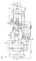
- FIG. 1 is a block diagram showing a configuration example of the resonance type converter 1 according to the first embodiment.
- the resonance type converter 1 is an insulating resonance type in which a DC input voltage Vin input from a DC voltage source 120 is converted into an AC and resonated, and then rectified and converted into a DC output voltage Vout again. It is a DCDC converter.
- the resonance type converter 1 includes a full bridge inverter 140, a transformer 100, a rectifying unit 150, a load R1, resistors R2, capacitors C1 and C2, current detecting units 131 and 132, and a control unit 110.
- the full bridge inverter 140 includes switching elements G1 to G4.
- the transformer 100 includes a primary winding 101, a first secondary winding 102, and a second secondary winding 103.
- the rectifying unit 150 is an example of the “secondary conversion unit” of the present disclosure, and includes a switch S1 and a diode D1 connected in parallel, and a switch S2 and a diode D2 connected in parallel.
- the switches S1 and S2 are switch elements such as a MOS transistor.
- the DC voltage source 120 generates a DC voltage Vin and supplies it to the full bridge inverter 140.
- the switching elements G1 to G4 of the full bridge inverter 140 are on / off controlled by the gate control signals Sg1 and Sg2 from the control unit 110. At this time, the switching elements G1 and G4 and the switching elements G2 and G3 are controlled to be turned on periodically and alternately. As a result, the input voltage Vin from the DC voltage source 120 is switched and smoothed by the capacitor C1, and the AC voltage is output to the primary winding 101 of the transformer 100.
- Excitation voltage is generated in the first and second secondary windings 102 and 103 by electromagnetic induction by the AC voltage flowing in the primary winding 101.
- the exciting voltages from the first and second secondary windings 102 and 103 are full-wave rectified by the switches S1 and S2 in a synchronous rectification method and smoothed by the resistor R2 and the capacitor C2 to generate a DC output voltage Vout. It is output.
- the current detection unit 131 outputs a signal SId1 indicating the current Id1 flowing from the first secondary winding 102 to the control unit 110, and the current detection unit 132 indicates the current Id2 flowing from the second secondary winding 103.
- the signal SId2 is output to the control unit 110.
- the control unit 110 has a gate control signal Sg1 that controls the switching elements G1 and G4, a gate control signal Sg2 that controls the switching elements G2 and G3 on and off, and a switch control signal Ss1 and Ss2 that controls the switches S1 and S2 on and off. Output.
- FIG. 2 is a block diagram showing a detailed configuration example of the control unit 110 of FIG.
- the control unit 110 includes a clock oscillator 111, an on-period detection unit 112, a gate control unit 113, and a switch control unit 114.
- the switch control unit 114 includes a storage unit 114m.
- the clock oscillator 111 outputs a clock signal Sklk to each of the on-period detection unit 112, the gate control unit 113, and the switch control unit 114, and causes the on-period detection unit 112, the gate control unit 113, and the switch control unit 114 to have a cycle.
- Periodic operation that is common in the cycle time Tc and has the same phase is performed.
- one cycle of this common periodic operation is referred to as "one cycle".
- the on-period detection unit 112 has the first on-period T1 in which the current Id1 is flowing in one cycle and the current Id2 flowing based on the signals SId1 and SId2 from the current detection units 131 and 132.
- the second ON period T2 is detected, and the information of the first and second ON periods T1 and T2 is output to the switch control unit 114.
- the gate control unit 113 has a gate control signal Sg1 that is on only for the first half of one cycle (the length of Tc / 2 from the start of the cycle) and is off for the rest of the cycle, and the first half of one cycle. It generates and outputs a gate control signal Sg2 that is off for a minute period and is on for the rest of the period.
- the switch control unit 114 stores the information of the first and second on periods T1 and T2 output from the on period detection unit in the storage unit 114m. Further, the switch control unit 114 reads the first on period T1 in the immediately preceding cycle from the storage unit 114m, and is on in the first on period T1 in the immediately preceding cycle of one cycle, and is off in the remaining period. The switch control signal Ss1 is generated. Similarly, the switch control unit 114 generates a switch control signal Ss2 that is on in the second on period T2 in the immediately preceding cycle of one cycle and is off in the other period. The switch control unit 114 outputs switch control signals Ss1 and Ss2 to the first and second switches S1 and S2, respectively.
- FIG. 3 is a timing chart showing operation waveforms of signals and the like in each part of the resonance type converter 1 of FIG.
- the switch control signal Ss1 that controls the switch S1 is turned on only during the period when the current Id1 is flowing, and is turned off during the other period.
- the switch control signal Ss2 is turned on only during the period when the current Id2 is flowing, and is turned off during the other period.
- the resonance type converter 1 turns on the switches S1 and S2, respectively, during the first and second on periods in the immediately preceding cycle. As a result, it is possible to prevent the current from flowing back through the switches S1 and S2, and to reduce the power conversion efficiency and the heat generation. Further, since there is a grace period from the detection of the first and second on periods T1 and T2 to the generation of the control signals Ss1 and Ss2, the influence of the delay of the switch control caused by the digital control can be reduced. it can.
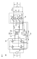
- FIG. 4 is a block diagram showing a configuration example of the resonance type converter 1A according to the second embodiment.
- FIG. 5 is a block diagram showing a detailed configuration example of the control unit 110A of FIG.
- the resonant converter 1A differs from the resonant converter 1 of FIG. 1 in the following points.
- a control unit 110A is provided in place of the control unit 110.
- a voltage detection unit 133 for detecting the output voltage Vout and a current detection unit 134 for detecting the output current Iout are further provided.
- the control unit 110A includes a switch control unit 114A instead of the switch control unit 114, and changes the control operation according to the value of the output current Iout. The operating principle when the output current Iout changes will be described below.
- FIG. 6 is a graph showing an example of the waveform of the current Id1 when the output current Iout is changed.
- the waveform when the output current Iout is large (for example, 175A) is shown in the curve 410
- the waveform when the output current Iout is small is shown in the curve 430
- the output current Iout is medium in magnitude (for example, 10A).
- the waveform in the case of 80A is shown in curve 420.
- the first and second on periods T1 and T2 detected for controlling the switches S1 and S2 in the first embodiment change depending on the value of the output current Iout, and the output current Iout is small.
- the start and end of the first and second on periods T1 and T2 are delayed. Therefore, when the output current Iout fluctuates greatly during one cycle, when the control as in the first embodiment is performed, the period during which the currents Id1 and Id2 are actually flowing in the forward direction and the switches S1 and S2 are turned on. The period does not match, and a backflow of current occurs.
- FIG. 7 is a flowchart showing an example of a switch control operation by the control unit 110A of FIG. In FIG. 7, the switch control operation includes steps S401 to S407.
- step S401 the control unit 110A turns on the switches S1 and S2 according to the first and second on periods T1 and T2 of the immediately preceding cycle, as in the first embodiment.
- step S401 the switch control operation proceeds to step S402.
- step S402 the control unit 110A determines whether or not the output current Iout fluctuates by a difference larger than a predetermined value during one cycle. If the output current Iout fluctuates, the switch control operation proceeds to step S403. If it has not changed, the switch control operation repeats step S401. Therefore, when the fluctuation of the output current Iout is sufficiently small, the switch is controlled in the same manner as in the first embodiment.
- step S403 the control unit 110A turns on the switches S1 and S2 according to the common on period Tc of FIG.
- the first on-period T1 also fluctuates.
- the common on-period Tc of FIG. 6 the current Id1 flows regardless of the value of the output current Iout. Therefore, even when the output current Iout fluctuates greatly, backflow can be prevented by turning on the switch S1 only during the common on period Pc.
- step S403 the switch control operation proceeds to step S404.
- step S404 the control unit 110A determines whether the output current Iout is smaller than the predetermined threshold value Is, that is, whether Iout ⁇ Ith is satisfied. If it is established, the switch control operation proceeds to step S405, and if not, the switch control operation proceeds to step S406.
- step S405 the control unit 110A leaves switches S1 and S2 off for one cycle. That is, the isolated resonance type converter is operated by the asynchronous rectification method.
- the output current Iout is sufficiently small, it is difficult to detect fluctuations in the output current Iout. Further, since the values of the currents Id1 and Id2 are small, the power consumption due to the resistors of the diodes D1 and D2 is small. Therefore, even if the switches S1 and S2 are always turned off and asynchronous rectification is performed, the same effect as when synchronous rectification is performed can be obtained.
- step S405 the switch control operation returns to step S404. Therefore, as long as the output voltage Iout is smaller than the predetermined threshold value Is, the control unit 110A repeats step S405.
- step S406 the control unit 110A determines whether or not the output current Iout has fluctuated for a predetermined number of cycles. If the output current Iout fluctuates, the switch control operation returns to step S404. If it has not changed, the switch control operation proceeds to step S407.
- step S407 the control unit 110A turns on the switches S1 and S2 during the first and second on periods one cycle before, as in step S401, for a period of a predetermined number of cycles. When the predetermined number of cycles has elapsed, the switch control operation returns to step S401. In other words, in step S407, the control unit 110A performs the same operation as in step S401 without monitoring the fluctuation of the output current Iout until the output current Iout stabilizes.
- the resonance type converter 1A changes the switch control operation according to the value of the output current Iout. As a result, even when the output current Iout changes significantly, it is possible to prevent the current from flowing back through the switches S1 and S2, and to reduce the power conversion efficiency and the heat generation.
- the monitoring value to be monitored to change the switch control operation is not limited to the output current Iout, and is, for example, the output current Iout, the input voltage Vin measured by the voltage detection unit 137, the output voltage Vout, and the temperature detection units 135 and 136. At least one of the measured temperatures tmp1 and tpp2 of the switches S1 and S2 may be set as a monitoring value and used as a reference for changing the switch control operation.
- FIG. 8 is a block diagram showing a configuration example of the resonance type converter 1B according to the third embodiment.
- the resonant converter 1B differs from the resonant converter 1 of FIG. 1 in the following points.
- (1) instead of the current detection units 131 and 132, the detection resistors Rd1 and Rd2 inserted at the positions of the current detection units 131 and 132 and the detection voltages Vd1 and Vd2 at both ends of the detection resistors Rd1 and Rd2 are detected.
- the voltage detection units 131B and 132B that output the signals SVd1 and SVd2 to the control unit 110B are provided.
- the control unit 110B detects the on-periods T1 and T2 based on the voltage signals SVd1 and SVd2 instead of the current signals SId1 and SId2.
- the detection resistors Rd1 and Rd2 generate detection voltages Vd1 and Vd2 by the currents Id1 and Id2 flowing through them, respectively. Therefore, by setting the periods in which the detection voltages Vd1 and Vd2 corresponding to the currents Id1 and Id2 are equal to or higher than the predetermined values as the on periods T1 and T2, the first and second on periods T1 and the same as in the first embodiment are set. T2 can be detected.
- FIG. 9 is a block diagram showing a configuration example of the resonance type converter 1C according to the fourth embodiment.
- the resonance type converter 1C differs from the resonance type converter 1A of FIG. 4 in the following points.
- (1) instead of the current detection units 131 and 132, the detection resistors Rd1 and Rd2 inserted at the positions of the current detection units 131 and 132 and the detection voltages Vd1 and Vd2 at both ends of the detection resistors Rd1 and Rd2 are detected.
- the voltage detection units 131B and 132B that output the signals SVd1 and SVd2 to the control unit 110C are provided.
- the control unit 110C detects the on-periods T1 and T2 based on the voltage signals SVd1 and SVd2 instead of the current signals SId1 and SId2. Thereby, the detection voltages Vd1 and Vd2 corresponding to the currents Id1 and Id2 can be detected, and the first and second on periods T1 and T2 can be detected as in the third embodiment.
- FIG. 10 is a block diagram showing a configuration example of the resonance type converter 1D according to the fifth embodiment.
- the resonant converter 1D differs from the resonant converter 1 of FIG. 1 in the following points.
- the switches S1D and S2D have a predetermined on-loss resistance when turned on.
- voltage detection units 131D and 132D are provided, which measure Vd1 and Vd2 for the voltages across the switches S1D and S2D and output the signals SVd1 and SVd2 to the control unit 110D.
- the control unit 110D detects the on-periods T1 and T2 based on the voltage signals SVd1 and SVd2 instead of the current signals SId1 and SId2.
- the currents Id1 and Id2 are detected by measuring the voltage across the switches S1D and S2D as in the third and fourth embodiments.
- the on period T1 and T2 can be detected.
- FIG. 11 is a block diagram showing a configuration of the resonance type converter 1E according to the sixth embodiment.
- the resonant converter 1E of FIG. 11 differs from the resonant converter 1 of FIG. 1 in the following points.
- the voltage detection units 131D and 132D are provided in place of the current detection units 131 and 132.
- a control unit 110E is provided in place of the control unit 110.
- the control unit 110E outputs the control signals Ss1E and Ss2E to the switches S1 and S2.
- FIG. 12 is a timing chart showing operation waveforms of signals and the like in each part of the resonance type converter 1E of FIG.
- the on period T1p indicates the on period in the immediately preceding cycle
- the on period T1m indicates the period for controlling the switch S1 to be turned on in the current cycle
- the on period T2p indicates the on period in the immediately preceding cycle
- the on period T2m indicates the period for controlling the switch S2 to be turned on in the current cycle.
- the periods Tdon and Tdoff are periods having a predetermined minute time ( ⁇ T1p, T2p), respectively. As shown in FIG.
- the control unit 110E delays the start timing by the period Tdon and advances the end timing by the period Tdoff, respectively, from the on periods T1p and T1p in the immediately preceding cycle, respectively, during the periods T1m and T2m.
- the switches S1 and S2 are turned on, respectively. The reason for advancing the end timing is to prevent backflow of current.
- the switches S1 and S2 are not turned on during the period Tdon and Tdoff.
- the currents Id1 and Id2 flow through the diodes D1 and D2, respectively. Therefore, for example, the currents Id1 and Id2 are detected by measuring the voltage across the switches S1 and S2, that is, the voltage across the diodes D1 and D2 using the voltage detection units 131D and 132D in FIG. The start timing and end timing of T2 can be substantially detected.
- the switches S1 and S2 are turned on during the period in which the start timing of the on period T1p and T2p of the immediately preceding cycle is delayed by the period Tdon and the end timing is advanced by the period Tdoff, and both ends of the diodes D1 and D2 are turned on.
- the start and end timings of the on periods T1 and T2 can be detected, and the on periods T1 and T2 can be substantially detected.
- the control units 110 and 110A turn on the switches S1 and S2 based on the first and second on periods in one cycle immediately before the current cycle.
- this is not limited to the one cycle immediately preceding the current cycle, and may be the on-periods T1 and T2 in at least one cycle up to immediately before the current cycle.
- the switches S1 and S2 are controlled to be turned on at the on period of the cycle two cycles before the current cycle, or at the average of the on periods T1 and T2 one cycle before and the on periods T1 and T2 two cycles before.
- the full bridge inverter 140 is used as the primary side conversion unit for converting the DC voltage into the AC voltage, but the present invention is not limited to this, and other primary side conversion such as a half bridge inverter or an LLC inverter is not limited to this. Parts may be used.
- control device and the like of the present disclosure can be applied to a digitally controlled and synchronous rectification type DCDC converter.
- 1,1A to 1E Resonant converter 100 Transformer 101 Primary winding 102, 103 Secondary winding 110, 110A to 110E Control unit 111 Clock oscillator 112 On-period detection unit 113 Gate control unit 114, 114A Switch control unit 114m Storage unit 120 DC voltage source 131, 132, 134 Current detection unit 131B, 131D, 131E, 132B, 132D, 132E Voltage detection unit 133,137 Voltage detection unit 135, 136 Temperature detection unit 140 Full bridge Inverter 150 Rectifier unit C1, C2 Capacitor D1, D2 Capacitor R1 Load R2 Resistor Rd1, Rd2 Detection resistor S1, S1D, S2, S2D Switch element
Landscapes
- Engineering & Computer Science (AREA)
- Power Engineering (AREA)
- Dc-Dc Converters (AREA)
Priority Applications (2)
| Application Number | Priority Date | Filing Date | Title |
|---|---|---|---|
| PCT/JP2019/031870 WO2021029018A1 (ja) | 2019-08-13 | 2019-08-13 | Dcdc変換装置の制御装置 |
| JP2021539749A JP7243839B2 (ja) | 2019-08-13 | 2019-08-13 | Dcdc変換装置の制御装置 |
Applications Claiming Priority (1)
| Application Number | Priority Date | Filing Date | Title |
|---|---|---|---|
| PCT/JP2019/031870 WO2021029018A1 (ja) | 2019-08-13 | 2019-08-13 | Dcdc変換装置の制御装置 |
Publications (1)
| Publication Number | Publication Date |
|---|---|
| WO2021029018A1 true WO2021029018A1 (ja) | 2021-02-18 |
Family
ID=74570965
Family Applications (1)
| Application Number | Title | Priority Date | Filing Date |
|---|---|---|---|
| PCT/JP2019/031870 Ceased WO2021029018A1 (ja) | 2019-08-13 | 2019-08-13 | Dcdc変換装置の制御装置 |
Country Status (2)
| Country | Link |
|---|---|
| JP (1) | JP7243839B2 (https=) |
| WO (1) | WO2021029018A1 (https=) |
Cited By (2)
| Publication number | Priority date | Publication date | Assignee | Title |
|---|---|---|---|---|
| JP2025004622A (ja) * | 2023-06-26 | 2025-01-15 | 本田技研工業株式会社 | 非接触電力伝送システム |
| WO2025197296A1 (ja) * | 2024-03-21 | 2025-09-25 | パナソニックIpマネジメント株式会社 | 電力変換器およびその制御方法 |
Citations (5)
| Publication number | Priority date | Publication date | Assignee | Title |
|---|---|---|---|---|
| JP2001309580A (ja) * | 2000-04-25 | 2001-11-02 | Matsushita Electric Works Ltd | 非接触電力伝達装置 |
| JP2008035641A (ja) * | 2006-07-28 | 2008-02-14 | Fuji Electric Device Technology Co Ltd | Dc−dcコンバータの制御回路及び方法 |
| US20150229226A1 (en) * | 2014-02-11 | 2015-08-13 | Fairchild Korea Semiconductor Ltd. | Resonant converter and driving method thereof |
| JP2018057132A (ja) * | 2016-09-28 | 2018-04-05 | サンケン電気株式会社 | 同期整流素子駆動装置及び同期整流素子駆動方法 |
| JP2018182882A (ja) * | 2017-04-11 | 2018-11-15 | 株式会社デンソー | 電力変換回路の制御装置、電力変換装置 |
-
2019
- 2019-08-13 WO PCT/JP2019/031870 patent/WO2021029018A1/ja not_active Ceased
- 2019-08-13 JP JP2021539749A patent/JP7243839B2/ja active Active
Patent Citations (5)
| Publication number | Priority date | Publication date | Assignee | Title |
|---|---|---|---|---|
| JP2001309580A (ja) * | 2000-04-25 | 2001-11-02 | Matsushita Electric Works Ltd | 非接触電力伝達装置 |
| JP2008035641A (ja) * | 2006-07-28 | 2008-02-14 | Fuji Electric Device Technology Co Ltd | Dc−dcコンバータの制御回路及び方法 |
| US20150229226A1 (en) * | 2014-02-11 | 2015-08-13 | Fairchild Korea Semiconductor Ltd. | Resonant converter and driving method thereof |
| JP2018057132A (ja) * | 2016-09-28 | 2018-04-05 | サンケン電気株式会社 | 同期整流素子駆動装置及び同期整流素子駆動方法 |
| JP2018182882A (ja) * | 2017-04-11 | 2018-11-15 | 株式会社デンソー | 電力変換回路の制御装置、電力変換装置 |
Cited By (4)
| Publication number | Priority date | Publication date | Assignee | Title |
|---|---|---|---|---|
| JP2025004622A (ja) * | 2023-06-26 | 2025-01-15 | 本田技研工業株式会社 | 非接触電力伝送システム |
| JP7682228B2 (ja) | 2023-06-26 | 2025-05-23 | 本田技研工業株式会社 | 非接触電力伝送システム |
| US12483070B2 (en) | 2023-06-26 | 2025-11-25 | Honda Motor Co., Ltd. | Non-contact power transmission system |
| WO2025197296A1 (ja) * | 2024-03-21 | 2025-09-25 | パナソニックIpマネジメント株式会社 | 電力変換器およびその制御方法 |
Also Published As
| Publication number | Publication date |
|---|---|
| JP7243839B2 (ja) | 2023-03-22 |
| JPWO2021029018A1 (https=) | 2021-02-18 |
Similar Documents
| Publication | Publication Date | Title |
|---|---|---|
| US12088190B2 (en) | Zero-voltage-switching control circuit, control method and switching power supply | |
| US10892687B2 (en) | Asymmetric power converter, power converters, and operating power converters | |
| JP4468011B2 (ja) | スイッチング電源及び画像形成装置 | |
| JP5115317B2 (ja) | スイッチング電源装置 | |
| EP2637295B1 (en) | Power supply device and image forming apparatus | |
| CN103780063B (zh) | 用于确定去磁零电流时间的方法和电路布置 | |
| US8295062B2 (en) | Switching power supply apparatus and semiconductor device | |
| JP4862432B2 (ja) | スイッチング電源装置 | |
| KR101468719B1 (ko) | 전력 변환기 및 그 구동 방법 | |
| US20140169049A1 (en) | Controller for a Power Converter and Method of Operating the Same | |
| JP5170241B2 (ja) | 絶縁型スイッチング電源装置 | |
| JP3116338B2 (ja) | スイッチング電源 | |
| WO2010146642A1 (ja) | スイッチング電源装置および半導体装置 | |
| CN114389456B (zh) | 同步整流器驱动器电路、集成电路、谐振转换器及方法 | |
| JP4835087B2 (ja) | Dc−dcコンバータ | |
| CN102396140A (zh) | 开关电源装置 | |
| TWI872457B (zh) | 用於llc電路的維持時間延長的功率轉換器及方法 | |
| JP2015122946A (ja) | 同期整流器及びそれを制御する方法 | |
| JP5644954B2 (ja) | 絶縁型スイッチング電源装置 | |
| JP7243839B2 (ja) | Dcdc変換装置の制御装置 | |
| JP2013251963A (ja) | 直流安定化電源 | |
| JP2017195664A (ja) | 共振形電源装置 | |
| JP4830467B2 (ja) | 共振形コンバータ | |
| JP2011083049A (ja) | 電圧変換装置 | |
| JPWO2021029018A5 (https=) |
Legal Events
| Date | Code | Title | Description |
|---|---|---|---|
| 121 | Ep: the epo has been informed by wipo that ep was designated in this application |
Ref document number: 19941761 Country of ref document: EP Kind code of ref document: A1 |
|
| ENP | Entry into the national phase |
Ref document number: 2021539749 Country of ref document: JP Kind code of ref document: A |
|
| NENP | Non-entry into the national phase |
Ref country code: DE |
|
| 122 | Ep: pct application non-entry in european phase |
Ref document number: 19941761 Country of ref document: EP Kind code of ref document: A1 |