WO2021024996A1 - 電子機器 - Google Patents
電子機器 Download PDFInfo
- Publication number
- WO2021024996A1 WO2021024996A1 PCT/JP2020/029710 JP2020029710W WO2021024996A1 WO 2021024996 A1 WO2021024996 A1 WO 2021024996A1 JP 2020029710 W JP2020029710 W JP 2020029710W WO 2021024996 A1 WO2021024996 A1 WO 2021024996A1
- Authority
- WO
- WIPO (PCT)
- Prior art keywords
- protective cover
- notch
- shape
- electronic device
- coin
- Prior art date
- Legal status (The legal status is an assumption and is not a legal conclusion. Google has not performed a legal analysis and makes no representation as to the accuracy of the status listed.)
- Ceased
Links
Images







Classifications
-
- G—PHYSICS
- G07—CHECKING-DEVICES
- G07F—COIN-FREED OR LIKE APPARATUS
- G07F1/00—Coin inlet arrangements; Coins specially adapted to operate coin-freed mechanisms
- G07F1/04—Coin chutes
- G07F1/041—Coin chutes with means, other than for testing currency, for dealing with inserted foreign matter, e.g. "stuffing", "stringing" or "salting"
- G07F1/045—Coin chutes with means, other than for testing currency, for dealing with inserted foreign matter, e.g. "stuffing", "stringing" or "salting" the foreign matter being in the form of liquids
-
- G—PHYSICS
- G07—CHECKING-DEVICES
- G07F—COIN-FREED OR LIKE APPARATUS
- G07F1/00—Coin inlet arrangements; Coins specially adapted to operate coin-freed mechanisms
- G07F1/02—Coin slots
-
- G—PHYSICS
- G06—COMPUTING OR CALCULATING; COUNTING
- G06Q—INFORMATION AND COMMUNICATION TECHNOLOGY [ICT] SPECIALLY ADAPTED FOR ADMINISTRATIVE, COMMERCIAL, FINANCIAL, MANAGERIAL OR SUPERVISORY PURPOSES; SYSTEMS OR METHODS SPECIALLY ADAPTED FOR ADMINISTRATIVE, COMMERCIAL, FINANCIAL, MANAGERIAL OR SUPERVISORY PURPOSES, NOT OTHERWISE PROVIDED FOR
- G06Q20/00—Payment architectures, schemes or protocols
- G06Q20/08—Payment architectures
- G06Q20/18—Payment architectures involving self-service terminals [SST], vending machines, kiosks or multimedia terminals
-
- G—PHYSICS
- G06—COMPUTING OR CALCULATING; COUNTING
- G06Q—INFORMATION AND COMMUNICATION TECHNOLOGY [ICT] SPECIALLY ADAPTED FOR ADMINISTRATIVE, COMMERCIAL, FINANCIAL, MANAGERIAL OR SUPERVISORY PURPOSES; SYSTEMS OR METHODS SPECIALLY ADAPTED FOR ADMINISTRATIVE, COMMERCIAL, FINANCIAL, MANAGERIAL OR SUPERVISORY PURPOSES, NOT OTHERWISE PROVIDED FOR
- G06Q20/00—Payment architectures, schemes or protocols
- G06Q20/08—Payment architectures
- G06Q20/20—Point-of-sale [POS] network systems
- G06Q20/208—Input by product or record sensing, e.g. weighing or scanner processing
-
- G—PHYSICS
- G07—CHECKING-DEVICES
- G07D—HANDLING OF COINS OR VALUABLE PAPERS, e.g. TESTING, SORTING BY DENOMINATIONS, COUNTING, DISPENSING, CHANGING OR DEPOSITING
- G07D1/00—Coin dispensers
- G07D1/02—Coin dispensers giving change
- G07D1/06—Coin dispensers giving change dispensing the difference between a sum paid and a sum charged
-
- G—PHYSICS
- G07—CHECKING-DEVICES
- G07D—HANDLING OF COINS OR VALUABLE PAPERS, e.g. TESTING, SORTING BY DENOMINATIONS, COUNTING, DISPENSING, CHANGING OR DEPOSITING
- G07D11/00—Devices accepting coins; Devices accepting, dispensing, sorting or counting valuable papers
- G07D11/10—Mechanical details
- G07D11/14—Inlet or outlet ports
-
- G—PHYSICS
- G07—CHECKING-DEVICES
- G07D—HANDLING OF COINS OR VALUABLE PAPERS, e.g. TESTING, SORTING BY DENOMINATIONS, COUNTING, DISPENSING, CHANGING OR DEPOSITING
- G07D11/00—Devices accepting coins; Devices accepting, dispensing, sorting or counting valuable papers
- G07D11/20—Controlling or monitoring the operation of devices; Data handling
- G07D11/26—Servicing, repairing or coping with irregularities, e.g. power failure or vandalism
-
- G—PHYSICS
- G07—CHECKING-DEVICES
- G07D—HANDLING OF COINS OR VALUABLE PAPERS, e.g. TESTING, SORTING BY DENOMINATIONS, COUNTING, DISPENSING, CHANGING OR DEPOSITING
- G07D11/00—Devices accepting coins; Devices accepting, dispensing, sorting or counting valuable papers
- G07D11/40—Device architecture, e.g. modular construction
-
- G—PHYSICS
- G07—CHECKING-DEVICES
- G07F—COIN-FREED OR LIKE APPARATUS
- G07F9/00—Details other than those peculiar to special kinds or types of apparatus
- G07F9/10—Casings or parts thereof, e.g. with means for heating or cooling
-
- G—PHYSICS
- G07—CHECKING-DEVICES
- G07G—REGISTERING THE RECEIPT OF CASH, VALUABLES, OR TOKENS
- G07G1/00—Cash registers
- G07G1/0018—Constructional details, e.g. of drawer, printing means, input means
-
- G—PHYSICS
- G07—CHECKING-DEVICES
- G07G—REGISTERING THE RECEIPT OF CASH, VALUABLES, OR TOKENS
- G07G1/00—Cash registers
- G07G1/0036—Checkout procedures
- G07G1/0045—Checkout procedures with a code reader for reading of an identifying code of the article to be registered, e.g. barcode reader or radio-frequency identity [RFID] reader
Definitions
- the present invention relates to an electronic device having a coin handling device.
- Electronic devices such as self-checkout (Point of Sales) terminal devices and self-payment devices (register devices) are provided with not only banknote handling devices that handle banknotes but also coin handling devices that handle coins.
- the electronic device having the coin handling device is provided with a coin insertion slot having a wide frontage so that a plurality of coins can be inserted at the same time.
- Japanese Patent Application Laid-Open No. 2013-088853 "Coin Handling Device” of Patent Document 1 assumes a small solid object such as a clip as a foreign substance and coins at the entrance of the coin slot.
- a lid member on which a coin is placed is provided, and a plurality of protrusions having a shape of removing foreign substances other than coins and moving only coins to a coin slot are formed on the lid member.
- An object of the present invention is to provide an electronic device capable of reducing the risk of foreign matter containing a liquid such as water invading a coin slot for inserting a plurality of coins at the same time.
- the electronic device mainly adopts the following characteristic configurations.
- the electronic device having a coin handling device that handles coins inserted from a coin slot. It has a plate-shaped protective cover to prevent foreign matter from entering through the coin slot.
- the protective cover has a notch having a size that allows a plurality of predetermined coins to pass through at the same time. It is characterized in that the peripheral portion of the notch portion adjacent to the notch portion of the protective cover or the surface of the protective cover is formed in a shape that allows drainage of liquid falling on the protective cover.
- an electronic device capable of reducing the risk of foreign matter containing a liquid such as water invading a coin slot for inserting a plurality of coins at the same time.
- FIG. 2A and FIG. 2B It is a schematic diagram which shows an example of the shape of the protective cover shown in FIG. 2A and FIG. 2B. It is a schematic diagram which shows an example of the shape of the protective cover shown in FIG. 2A and FIG. 2B. It is a schematic diagram which shows the 1st modification which makes the protective cover shown in FIG. 2A and FIG. 2B a protective cover having a shape different from FIG.
- FIG. 3A and FIG. 3B It is a schematic diagram which shows the 1st modification which makes the protective cover shown in FIG. 2A and FIG. 2B a protective cover having a shape different from FIG. 3A and FIG. 3B.
- 2 is a schematic view showing a second modification in which the protective cover shown in FIGS. 2A and 2B is a protective cover having a shape different from that of FIGS. 3A and 3B, 4A and 4B.
- 2 is a schematic view showing a second modification in which the protective cover shown in FIGS. 2A and 2B is a protective cover having a shape different from that of FIGS. 3A and 3B, 4A and 4B.
- FIGS. 2A and 2B a protective cover having a shape different from FIG. 3A and FIG. 3B, FIG. 4A and FIG. 4B, FIG. 5A and FIG. 5B.
- FIG. 2A and FIG. 2B a protective cover having a shape different from FIG. 3A and FIG. 3B, FIG. 4A and FIG. 4B, FIG. 5A and FIG.
- a fourth modification in which the protective cover shown in FIGS. 2A and 2B is a protective cover having a shape different from that of FIGS. 3A and 3B, 4A and 4B, 5A and 5B, and 6A and 6B.
- FIGS. 2A and 2B is a protective cover having a shape different from that of FIGS. 3A and 3B, 4A and 4B, 5A and 5B, and 6A and 6B.
- FIGS. 2A and 2B is a protective cover having a shape different from that of FIGS. 3A and 3B, 4A and 4B, 5A and 5B, and 6
- FIGS. 3A and 3B is a protective cover having a shape different from that of FIGS. 3A and 3B, 4A and 4B, 5A and 5B, and 6A and 6B.
- It is a schematic diagram which shows.
- it is a perspective view showing an example of the shape of a protective cover attached to an electronic device having a coin slot different from the shape of the coin slot of the electronic device shown in FIG. 1 as the second embodiment. ..
- it is a perspective view showing an example of the shape of a protective cover attached to an electronic device having a coin slot different from the shape of the coin slot of the electronic device shown in FIG. 1 as the second embodiment. ..
- As a first embodiment it is a perspective view showing an example of the shape of a protective cover attached to an electronic device having a coin slot different from the shape of the coin slot of the electronic device shown in FIG. 1 as the second embodiment. ..
- the present invention is an electronic device having a coin insertion slot for inserting coins, and has a plate shape having a notch portion having a size that allows a plurality of predetermined coins to pass through the surface of the coin insertion slot at the same time.
- the protective cover is attached, and the protective cover is mainly characterized by having a drainage groove or an inclined surface having a shape for draining the liquid falling on the protective cover around the notch. .. Therefore, the risk of foreign matter other than coins entering the coin slot is reduced, and the risk of liquid entering the coin slot even when liquid such as water or water droplets gets on the protective cover. Can be reduced.
- one of the main features is that it is possible to correspond to various coin insertion slots by making the shape of the protective cover match the shape of the coin insertion slot.
- FIG. 1 is a perspective view showing an example of an electronic device having a coin handling device according to the present invention.
- the electronic device an example of a self-POS terminal device that registers a product purchased by a customer himself / herself and settles the purchase price is shown.
- the self-POS terminal device that is, the electronic device 100
- the electronic device 100 has a bill slot 10 for a bill handling device that handles bills for cash settlement of the purchase price, and a coin slot 20 for a coin handling device that handles coins.
- It also has a bar code scanner 31 that reads the bar code of the product for product registration, a display 32 that displays the settlement information of the purchased product, etc., and a patrol lamp 41, etc. for notification of cash shortage etc. ing.
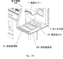
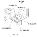
- FIGS. 2A and 2B are perspective views showing an example of the shape of the protective cover 1 attached to the coin slot 20 of the electronic device 100 shown in FIG.
- FIG. 2A shows a state in which the protective cover 1 is about to be attached to the coin slot 20
- FIG. 2B shows a state after the protective cover 1 is attached to the coin slot 20.
- the electronic device 100 has a coin insertion slot 20 that forms a substantially rectangular opening for inserting coins in the coin loading portion 20C on which coins for purchasing goods are placed. And a coin unfolding portion 22 formed of a U-shaped recess for unfolding coins.
- the coin insertion slot 20 forms an inclined surface in which the opening gradually narrows from the surface toward the lowermost end portion, and the lowermost lower end portion is a coin handling device mounted on the electronic device 100. It communicates with the coin slot of.
- the protective cover 1 has a substantially rectangular plate-like shape.
- One side of the protective cover 1 (the side in the front side direction of FIGS. 2A and 2B) is provided with a notch portion 2 having a size that allows a plurality of predetermined coins to pass through at the same time.
- the predetermined plurality of coins are, for example, two coins (500-yen coins) having the maximum size.
- the protective cover 1 covers the entire surface portion of the coin insertion slot 20 in a region other than the notch portion 2.
- the protective cover 1 when the protective cover 1 is attached to the surface of the coin insertion slot 20, the coin can be inserted into the coin insertion slot 20 only through the notch 2.
- the protective cover 1 is joined to the surface of the coin slot 20 by using an adhesive or the like so as to be in close contact with each other, and coins including liquids such as water and water droplets are contained from the periphery other than the notch portion 2. Any foreign matter other than the above is completely prevented from entering the coin slot 20.
- the customer when the customer performs self-payment of the purchased product, the customer deploys the coins for settlement to the coin expansion unit 22, selects an appropriate coin from the coins, takes them out from the coin expansion unit 22, and protects them. Since the operation of inserting the coin into the coin insertion slot 20 is performed through the notch 2 of the cover 1, it is possible to reduce the risk of foreign matter other than coins entering the coin insertion slot 20.
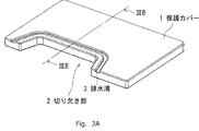
- FIGS. 2A and 2B are schematic views showing an example of the shape of the protective cover 1 shown in FIGS. 2A and 2B
- FIG. 3A shows a perspective view of the protective cover 1
- FIG. 3B is IIIB-IIIB of FIG. 3A.
- the cross-sectional shape of the protective cover 1 viewed from the direction is shown.
- a drainage groove 3 is formed on the surface of the protective cover 1 so as to be along the end edge of the notch peripheral portion 4.
- the notch portion peripheral portion 4 is a region having a constant width adjacent to the notch portion 2. Therefore, the drainage groove 3 is a protective cover 1 in which the notch portion 2 is formed at a position on the opposite end side of the notch portion peripheral portion 4 adjacent to the notch portion 2 and facing the notch portion 2. It can be said that it is formed so as to be parallel to the side, that is, along the end side of the notch peripheral portion 4.
- the drainage groove 3 has a shape that allows liquids such as water that may fall on the protective cover 1 to be drained to the outside of the protective cover 1 when coins are inserted, and is formed on the edge of the notch peripheral portion 4. As shown in the cross-sectional view of FIG. 3B, it has a side surface that is inclined so that the width gradually narrows toward the bottom surface, and has a shape that facilitates the collection of liquid on the bottom surface. I'm doing it.
- a plate-shaped protective cover 1 that reduces the risk of foreign matter other than coins invading the coin insertion slot 20 for inserting coins is attached.
- the protective cover 1 has a notch portion 2 having a size that allows a plurality of predetermined coins to pass through at the same time, and the periphery of the notch portion adjacent to the notch portion 2 in the protective cover 1.
- the surface shape of the part 4 is formed into a shape that enables drainage.
- the protective cover 1 has a shape that enables the drainage, and the liquid is formed along the edge of the notch peripheral portion 4 located on the opposite side of the notch portion 2.
- a drainage groove 3 is formed to drain water to the outside of the protective cover 1, and the side surface of the drainage groove 3 is formed so as to be inclined in a direction in which the opening gradually narrows toward the bottom surface of the drainage groove 3. doing.
- the shape of the bottom surface of the drainage groove 3 is also considered so that the liquid can be easily drained from the drainage groove 3 to the outside without accumulating on the bottom surface.
- the bottom surface of the drainage groove 3 has an inclined surface that is inclined from one end in the longitudinal direction of the drainage groove 3 toward the other end (for example, from the back side to the front side in FIGS. 3A and 3B).
- the protective cover 1 has a shape in which the thickness of the portion forming the bottom surface of the drainage groove 3 gradually becomes thinner toward the other end.
- the surface of the notch peripheral portion 4 of the plate-shaped protective cover 1 is also around the notch so as to have an inclined surface inclined in the opposite direction of the notch 2, that is, toward the drainage groove 3. It is desirable that the thickness of the portion 4 is formed so as to gradually become thinner toward the drainage groove 3.
- a notch portion 2 having a size that allows a plurality of predetermined coins to pass at the same time is excluded. Therefore, it is possible to prevent foreign substances other than coins, such as liquids such as water, from entering the coin slot 20. Further, even when a liquid such as water falls on the notch portion peripheral portion 4 adjacent to the notch portion 2, the dropped liquid flows down to the drainage groove 3 instead of the notch portion 2 side and is discharged. Therefore, it is possible to prevent a liquid such as water from flowing into the coin slot 20.
- the shape of the protective cover 1 that reduces the risk of foreign matter other than coins entering the coin slot 20 is not limited to the case shown in FIGS. 3A and 3B as a shape that enables drainage of the protective cover 1. Other shapes may be used.
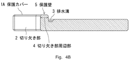
- FIGS. 4A and 4B are schematic views showing a first modification in which the protective cover 1 shown in FIGS. 2A and 2B is a protective cover 1A having a shape different from that of FIGS. 3A and 3B, and FIG. 4A is a protective diagram.
- a perspective view of the cover 1A is shown, and FIG. 4B shows a cross-sectional shape of the protective cover 1A viewed from the IVB-IVB direction of FIG. 4A (the same direction as the IIIB-IIIB direction of FIG. 3A).
- a drainage groove 3 similar to the protective cover 1 of FIGS. 3A and 3B is cut at the notch peripheral portion 4 adjacent to the notch 2. It is formed at the position of the end side opposite to the notch portion 2.
- the protective cover 1A of FIGS. 4A and 4B further protects the notched peripheral portion 4 to have a thicker shape than the other portions of the plate-shaped protective cover 1A as shown in the cross-sectional view of FIG. 4B. It is formed as a wall 5.
- the coin slot 20 is formed even when the liquid falls on the surface of the protective wall 5.
- the protective wall 5 has an inclined surface inclined in the opposite direction of the notch 2, that is, an inclined surface inclined toward the drainage groove 3 so as to facilitate the flow toward the drainage groove 3 without flowing to the side. It is desirable to form the shape so that the thickness gradually becomes thinner toward the opposite direction of the notch portion 2.
- a notch portion 2 having a size that allows a plurality of predetermined coins to pass at the same time is excluded. Therefore, foreign substances other than coins, such as liquids such as water, can be prevented from entering the coin slot 20 as in the case of the protective cover 1 of FIGS. 3A and 3B.
- the surface of the protective wall 5 formed in the peripheral portion 4 of the notch portion adjacent to the notch portion 2 is formed to be inclined in the opposite direction of the notch portion 2, that is, in the direction of the drainage groove 3. As a result, even if a liquid such as water falls on the protective wall 5, the dropped liquid will flow down to the drainage groove 3 instead of the notch 2 side and be discharged. Can be prevented from flowing into the coin slot 20.
- FIGS. 5A and 5B are schematic views showing a second modification in which the protective cover 1 shown in FIGS. 2A and 2B is a protective cover 1B having a shape different from that of FIGS. 3A and 3B, 4A and 4B.
- 5A shows a perspective view of the protective cover 1B
- FIG. 5B shows the cross-sectional shape of the protective cover 1B viewed from the VB-VB direction of FIG. 5A (the same direction as the IIIB-IIIB direction of FIG. 3A). ..
- the same protective wall 5 as in the case of the protective cover 1B of FIGS. 4A and 4B is formed in the peripheral portion 4 of the notch, but is cut.
- the drainage groove 3 is not formed at the position of the end side of the notch peripheral portion 4 opposite to the notch portion 2.
- the shape of the surface of the protective wall 5 formed around the notch portion 4 of the plate-shaped protective cover 1 is inclined toward the opposite direction of the notch portion 2 as in the case of FIGS. 4A and 4B. It is desirable to form the protective wall 5 in a shape in which the thickness of the protective wall 5 gradually becomes thinner in the opposite direction of the notch portion 2 so as to have an inclined surface.
- a notch portion 2 having a size that allows a plurality of predetermined coins to pass at the same time is excluded. Therefore, foreign substances other than coins, such as liquids such as water, can be prevented from entering the coin slot 20 as in the case of FIGS. 4A and 4B. Furthermore, liquids such as water are protected by forming the surface of the protective wall 5 formed in the peripheral portion 4 of the notch portion adjacent to the notch portion 2 so as to be inclined toward the opposite direction of the notch portion 2.
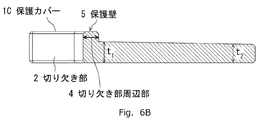
- FIGS. 6A and 6B show a third modification in which the protective cover 1 shown in FIGS. 2A and 2B is a protective cover 1C having a shape different from that of FIGS. 3A and 3B, 4A and 4B, and 5A and 5B.
- FIG. 6A is a schematic view showing an example
- FIG. 6A shows a perspective view of the protective cover 1C
- FIG. 6B shows the protective cover 1C viewed from the VIB-VIB direction of FIG. 6A (the same direction as the IIIB-IIIB direction of FIG. 3A).
- the cross-sectional shape is shown.
- the protective wall 5 is formed around the notch portion 4, but it is cut.
- the drainage groove 3 is not formed at the position of the end side of the notch portion peripheral portion 4 opposite to the notch portion 2.
- the surfaces of the protective cover 1C shown in FIGS. 6A and 6B other than the peripheral portion 4 of the notch portion are directed toward the opposite side of the notch portion 2, that is, the protective cover 1C in which the notch portion 2 is formed.
- a shape in which the thickness of the portion other than the notch portion peripheral portion 4 gradually becomes thinner toward the opposite direction of the notch portion 2 so as to have an inclined surface inclined toward the opposite side facing the side of To form.
- the thickness of the protective cover 1C in the vicinity of the notch peripheral portion 4 is t 1 , and the vicinity of the side opposite to the side of the protective cover 1C in which the notch portion 2 is formed.
- t 2 be the thickness of t 1 > t 2
- the thickness of the protective cover 1C is toward the opposite side of the notch portion 2, that is, on the side opposite to the side of the protective cover 1 in which the notch portion 2 is formed. It is formed into a shape that gradually becomes thinner toward the end.
- the shape of the surface of the protective wall 5 formed around the notch portion 4 of the plate-shaped protective cover 1 is inclined toward the opposite direction of the notch portion 2 as in the case of FIGS. 4A and 4B. It is desirable to form the protective wall 5 in a shape in which the thickness of the protective wall 5 gradually becomes thinner in the opposite direction of the notch portion 2 so as to have an inclined surface.
- the dropped liquid flows down in the direction opposite to the notch portion 2 instead of the notch portion 2 side. It is possible to prevent the coin from flowing down into the coin slot 20.
- the shape of the surface of the protective wall 5 formed around the notch portion 4 of the plate-shaped protective cover 1 is also directed in the direction opposite to the notch portion 2 as in the case of FIGS. 4A and 4B. It is desirable to have a shape with an inclined inclined surface.
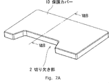
- FIGS. 7A and 7B show the protective cover 1 shown in FIGS. 2A and 2B having a different shape from that of FIGS. 3A and 3B, 4A and 4B, 5A and 5B, and 6A and 6B.
- 7A is a perspective view of the protective cover 1D
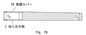
- FIG. 7B is an arrow from the VIIB-VIIB direction of FIG. 7A (the same direction as the IIIB-IIIB direction of FIG. 3A).
- the cross-sectional shape of the visible protective cover 1D is shown.
- the surface of the protective cover 1D of FIGS. 7A and 7B has an inclined surface inclined from each end side of the cutout portion of the protective cover 1D forming the notch portion 2 toward the outer peripheral side.
- the thickness of 1D is formed so as to gradually become thinner toward the opposite direction of the notch portion 2.
- the thickness in the vicinity of the side of the protective cover 1D in which the notch 2 is formed is t 0
- the thickness on the opposite side facing the side of the protective cover 1D in which the notch 2 is formed is t 0 .
- the thickness of the protective cover 1D gradually becomes thinner toward the opposite direction of the notch portion 2.
- FIGS. 8A, 8B and 8C are examples of the shape of the protective cover attached to the electronic device having a coin slot different from the shape of the coin slot 20 of the electronic device 100 shown in FIG. 1 as the first embodiment. Is a perspective view showing the second embodiment.
- FIGS. 1, 2A and 2B described above as the first embodiment the case of the electronic device 100 having the coin slot 20 having a substantially rectangular shape is shown, but FIG. 8A is the second embodiment.
- the electronic device 100A shown in FIGS. 8B and 8C shows a case where the coin slot 20A has a substantially circular shape.
- the protective cover 1E for reducing the risk of foreign matter such as water other than coins entering the coin slot 20A is also matched to the shape of the coin slot 20A. It is formed in a substantially circular shape.
- FIG. 8A shows a state in which a substantially circular protective cover 1E is to be attached to an electronic device 100A having a substantially circular coin slot 20A
- FIG. 8B shows a state in which the protective cover 1E is attached to the electronic device 100A. It shows the state after the operation.
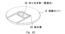
- FIG. 8C shows a perspective view of the protective cover 1E having a substantially circular shape.
- the substantially circular coin insertion slot 20A has an opening gradually increasing from the surface toward the lowermost end portion, as in the case of the coin insertion slot 20 of FIGS. 2A and 2B in the first embodiment. It forms an inclined surface that becomes narrower, and the lowermost end is at the coin slot of the coin handling device (not shown in FIGS. 8A, 8B, and 8C) mounted on the electronic device 100A. Communicating.
- the protective cover 1E has a notch portion 2A having a size that allows a plurality of predetermined coins to pass simultaneously in the vicinity of the central portion of the protective cover 1E. It has a plate-like shape with (in other words, a through hole). Then, as in the case shown in FIG. 2B as the first embodiment, the protective cover 1E covers the entire surface portion of the coin insertion slot 20A except for the notch portion 2A (through hole) as shown in FIG. 8B. It is attached to the surface of the coin insertion slot 20A so as to cover it, and the coin can be inserted into the coin insertion slot 20A only through the notch 2A.
- FIG. 8B the case of FIG.
- the protective cover 1E is joined to the surface of the coin slot 20A by using an adhesive or the like, and liquid such as water or water droplets is applied from the periphery other than the notch 2A. It is in a state of completely preventing foreign matter other than coins, including coins, from entering the coin slot 20A.
- drainage is formed in a U shape on the surface of the protective cover 1E so as to surround the notch 2A at the periphery of the notch adjacent to the notch 2A (through hole).
- a groove 3A is formed, and both ends of the drainage groove 3A reach the outer peripheral portion of the protective cover 1E.
- the drainage groove 3A is a groove for draining a liquid such as water that may be mixed when inserting coins to the outside of the protective cover 1E, as in the case of FIGS. 3A and 3B of the first embodiment. Similarly, it has a side surface that is inclined so that the width gradually narrows toward the bottom surface, so that the liquid can easily collect on the bottom surface.
- the liquid does not collect on the bottom surface and can be easily drained from the drainage groove 3A to the outside.
- the bottom surface of the drainage groove 3A has a shape inclined from the vicinity of the center in the length direction of the drainage groove 3A (the position substantially at the center of the peripheral portion of the notch) toward both ends.
- the surface of the plate-shaped protective cover 1E around the notch portion is also notched so as to have an inclined surface inclined in the opposite direction of the notch portion 2A, that is, in the direction of the drainage groove 3A. It is desirable to form the peripheral portion so that the thickness gradually becomes thinner in the direction opposite to the notch portion 2A, that is, in the direction of the drainage groove 3A.
- the substantially circular protective cover 1E as shown in FIG. 8 By attaching the substantially circular protective cover 1E as shown in FIG. 8 to the substantially circular coin slot 20A of the electronic device 100A, a plurality of predetermined coins pass at the same time as in the case of the first embodiment. Except for the notch portion 2A having a size that allows this, it is possible to reduce the risk of foreign matter other than coins, such as liquids such as water, entering the coin slot 20A. Further, even if a liquid such as water falls on the peripheral portion of the notch portion adjacent to the notch portion 2A, the dropped liquid flows down to the drainage groove 3A instead of the notch portion 2A side and is discharged. Therefore, it is possible to prevent the coin from flowing into the coin slot 20A.
- the shape of the coin slot 20A matches the surface shape of the coin slot 20A.
- the circular protective cover 1E attaches to the coin slot 20A, it is possible to reduce the risk of foreign matter other than coins entering the coin slot 20A.
- the shape of the protective cover attached to the electronic device to match the shape of the surface of the coin slot to be attached in order to reduce the risk of foreign matter other than coins entering, any shape can be obtained. It is also possible to handle coin slots.
Landscapes
- Physics & Mathematics (AREA)
- General Physics & Mathematics (AREA)
- Business, Economics & Management (AREA)
- Accounting & Taxation (AREA)
- Finance (AREA)
- Strategic Management (AREA)
- General Business, Economics & Management (AREA)
- Engineering & Computer Science (AREA)
- Theoretical Computer Science (AREA)
- Control Of Vending Devices And Auxiliary Devices For Vending Devices (AREA)
- Cash Registers Or Receiving Machines (AREA)
Abstract
硬貨取扱装置を有する電子機器において、硬貨を投入するための硬貨投入口(20)に対して硬貨以外の異物の侵入を防ぐための板状の保護カバー(1)を取り付け、かつ、該保護カバー(1)は、所定の複数枚の硬貨が同時に通過することを許容する大きさの切り欠き部(2)を有し、かつ、該保護カバー(1)の切り欠き部(2)に隣接する切り欠き部周辺部または保護カバー(1)の表面形状を、保護カバー(1)上に落ちる液体の排水を可能にする形状に形成する。例えば、液体の排水を可能にする前記形状として、切り欠き部周辺部において切り欠き部(2)の反対側に位置する該切り欠き部周辺部の端辺に沿って液体を保護カバー(1)の外側に排水するための排水溝を形成する。これにより、水等の液体を含む異物が硬貨投入口に侵入する恐れを低減することが可能な電子機器を提供する。
Description
本発明は、硬貨取扱装置を有する電子機器に関する。
近年、店舗における代金の精算作業に関してセルフレジ化が普及しつつあり、店舗の店員のみならず、顧客も自分自身で代金の精算を行うようになってきている。セルフレジを行うセルフPOS(Point of Sales)端末装置やセルフ精算装置(レジスタ装置)等の電子機器には、紙幣を取り扱う紙幣取扱装置だけではなく、硬貨を取り扱う硬貨取扱装置が配置される。そして、該硬貨取扱装置を有する電子機器には、複数枚の硬貨を同時に投入することが可能になるように、間口が広い硬貨投入口が設けられる。
硬貨投入口には、硬貨以外の異物が誤って投入される恐れがある。教育された店舗の店員ではない顧客が自らの購入商品の代金の精算を行う場合は、硬貨以外の異物を誤って投入してしまう事態が増加することが懸念される。
かかる異物侵入対策のために、例えば、特許文献1の特開2013-088853号公報「硬貨取扱装置」は、異物として例えばクリップ等の小型の固形物を想定して、硬貨投入口の入り口に硬貨を載置する蓋部材を設け、該蓋部材に硬貨以外の異物を排除し硬貨のみを硬貨投入口に移動させる形状の複数の突起部を形成するという技術を提案している。
しかしながら、本発明に関連する前記特許文献1等に記載のような現状の技術においては、複数枚の硬貨を同時に投入することができない。
(本発明の目的)
本発明の目的は、複数枚の硬貨を同時に投入する硬貨投入口に、水等の液体を含む異物が侵入する恐れを低減することが可能な電子機器を提供することにある。
本発明の目的は、複数枚の硬貨を同時に投入する硬貨投入口に、水等の液体を含む異物が侵入する恐れを低減することが可能な電子機器を提供することにある。
前述の課題を解決するため、本発明による電子機器は、主に、次のような特徴的な構成を採用している。
本発明による電子機器は、
硬貨投入口から投入される硬貨を取り扱う硬貨取扱装置を有する電子機器であって、
前記硬貨投入口からの異物の侵入を防ぐための板状の保護カバーを有し、
前記保護カバーは、所定の複数枚の硬貨が同時に通過することを許容する大きさの切り欠き部を有し、
前記保護カバーの前記切り欠き部に隣接する切り欠き部周辺部または前記保護カバーの表面が、前記保護カバー上に落ちる液体の排水を可能にする形状に形成してある
ことを特徴とする。
硬貨投入口から投入される硬貨を取り扱う硬貨取扱装置を有する電子機器であって、
前記硬貨投入口からの異物の侵入を防ぐための板状の保護カバーを有し、
前記保護カバーは、所定の複数枚の硬貨が同時に通過することを許容する大きさの切り欠き部を有し、
前記保護カバーの前記切り欠き部に隣接する切り欠き部周辺部または前記保護カバーの表面が、前記保護カバー上に落ちる液体の排水を可能にする形状に形成してある
ことを特徴とする。
本発明によれば、複数枚の硬貨を同時に投入する硬貨投入口に、水等の液体を含む異物が侵入する恐れを低減することが可能な電子機器を提供することができる。
以下、本発明による硬貨取扱装置を有する電子機器の好適な実施形態について添付図を参照して説明する。なお、以下の説明においては、硬貨取扱装置を有する電子機器について説明するが、電子機器を購入商品に関する現金による精算処理を顧客自身が行うセルフPOS端末やセルフ精算装置とすることも可能であることは言うまでもない。また、以下の各図面に付した図面参照符号は、理解を助けるための一例として各要素に便宜上付記したものであり、本発明を図示の態様に限定することを意図するものではないことも言うまでもない。
(本発明の特徴)
本発明の実施形態の説明に先立って、本発明の特徴についてその概要をまず説明する。本発明は、硬貨を投入する硬貨投入口を有する電子機器であって、前記硬貨投入口表面に、所定の複数枚の硬貨が同時に通過することを許容する大きさの切り欠き部を有する板状の保護カバーを取り付け、かつ、前記保護カバーは、該保護カバー上に落ちる液体を前記切り欠き部の周辺に排水を行うための形状からなる排水溝または傾斜面を有することを主要な特徴としている。而して、硬貨投入口に硬貨以外の異物が侵入する恐れを低減し、かつ、水や水滴等の液体が保護カバー上にかかった場合であっても、硬貨投入口へ液体が侵入する恐れを低減することができる。
本発明の実施形態の説明に先立って、本発明の特徴についてその概要をまず説明する。本発明は、硬貨を投入する硬貨投入口を有する電子機器であって、前記硬貨投入口表面に、所定の複数枚の硬貨が同時に通過することを許容する大きさの切り欠き部を有する板状の保護カバーを取り付け、かつ、前記保護カバーは、該保護カバー上に落ちる液体を前記切り欠き部の周辺に排水を行うための形状からなる排水溝または傾斜面を有することを主要な特徴としている。而して、硬貨投入口に硬貨以外の異物が侵入する恐れを低減し、かつ、水や水滴等の液体が保護カバー上にかかった場合であっても、硬貨投入口へ液体が侵入する恐れを低減することができる。
さらに、保護カバーの形状を、硬貨投入口の形状に合わせた形状にすることにより、種々の硬貨投入口にも対応することが可能であることも主要な特徴の一つとしている。
(本発明の第1の実施形態の構成例)
次に、本発明に係る電子機器の第1の実施形態における構成例について、図面を参照しながら詳細に説明する。
次に、本発明に係る電子機器の第1の実施形態における構成例について、図面を参照しながら詳細に説明する。
図1は、本発明に係る硬貨取扱装置を有する電子機器の一例を示す斜視図である。ここでは、該電子機器として、顧客自身が購入する商品の商品登録を行って、購入代金の精算を行うセルフPOS端末装置の一例を示している。
図1に示すように、セルフPOS端末装置すなわち電子機器100は、購入代金の現金による精算用として紙幣を取り扱う紙幣取扱装置用の紙幣投入口10、硬貨を取り扱う硬貨取扱装置用の硬貨投入口20等を有するとともに、商品登録用として商品のバーコードを読み取るバーコードスキャナ31、購入商品の精算情報を表示するディスプレイ32等を有し、かつ、現金不足等の通知用としてパトランプ41等を有している。
ここで、図1には示していないが、硬貨投入口20には、水等の液体を含む異物が侵入する恐れを低減するために、本発明に特有の保護カバーとして、図2A及び図2Bに示す保護カバー1が取り付けられている。図2A及び図2Bは、図1に示した電子機器100の硬貨投入口20に取り付けられる保護カバー1の形状の一例を示す斜視図である。図2Aは、保護カバー1を硬貨投入口20に取り付けようとしている状態を示し、図2Bは、保護カバー1を硬貨投入口20に取り付けた後の状態を示している。
図2A及び図2Bに示すように、電子機器100は、商品購入用の硬貨を載置する硬貨載置部20Cに、硬貨を投入するための略矩形状の開口部を形成する硬貨投入口20と硬貨を展開するためのU字形状の凹部からなる硬貨展開部22とを有している。ここで、硬貨投入口20は、表面から最下端部に向かって開口部が徐々に狭くなっていく傾斜面を形成しており、最下端部は、電子機器100に搭載されている硬貨取扱装置の硬貨投入口に連通している。
また、図2A及び図2Bに示すように、保護カバー1は略矩形の板状の形状をなしている。該保護カバー1の一辺(図2A及び図2Bの手前側方向の辺)には、所定の複数枚の硬貨が同時に通過することを許容する大きさの切り欠き部2が設けてある。所定の複数枚の硬貨とは、例えば、サイズが最大である硬貨(500円玉)2枚である。そして、保護カバー1は、硬貨投入口20に取り付けられたとき、図2Bに示すように、切り欠き部2を除く領域において、硬貨投入口20の表面部全体を覆う。そこで、保護カバー1が硬貨投入口20の表面に取り付けられると、切り欠き部2を通してのみ硬貨を硬貨投入口20に投入することが可能な状態になる。ここで、保護カバー1は、硬貨投入口20の表面と互いに密着するように接着剤等を用いて接合されており、切り欠き部2以外の周辺からは、水や水滴等の液体を含め硬貨以外の如何なる異物も、硬貨投入口20に侵入することが完全に防げる状態になっている。
また、顧客が購入商品のセルフ精算を行う場合には、顧客は精算用の硬貨を硬貨展開部22に展開し、その中から適当な硬貨を選択して、硬貨展開部22から取り出して、保護カバー1の切り欠き部2を通して硬貨投入口20に投入する操作を行うので、硬貨投入口20に硬貨以外の異物が侵入する恐れを低減することができる。
次に、図2A及び図2Bに示した保護カバー1の形状についてさらに具体的に説明する。図3A及び図3Bは、図2A及び図2Bに示した保護カバー1の形状の一例を示す模式図であり、図3Aが保護カバー1の斜視図を示し、図3Bが図3AのIIIB-IIIB方向から矢視した保護カバー1の断面形状を示している。
図3に示すように、保護カバー1の表面には、排水溝3が、切り欠き部周辺部4の端辺に沿うように、形成されている。切り欠き部周辺部4は、切り欠き部2に隣接する一定幅の領域である。したがって、排水溝3は、切り欠き部2に隣接する切り欠き部周辺部4において切り欠き部2と対向する反対側の端辺の位置に、切り欠き部2が形成されている保護カバー1の辺と平行するように、すなわち、該切り欠き部周辺部4の端辺に沿うように、形成されている、と言える。排水溝3は、硬貨を投入する際に保護カバー1上に落ちる可能性がある水等の液体を保護カバー1の外側に排水することを可能にする形状として切り欠き部周辺部4の端辺に沿うように形成した溝であり、図3Bの断面図に示すように、底面に向かって徐々に幅が狭くなるように傾斜した側面を有していて、液体が底面に集まり易くなる形状をなしている。
つまり、図2A及び図2Bに示したように、電子機器100では、硬貨を投入するための硬貨投入口20に対して硬貨以外の異物の侵入の恐れを低減する板状の保護カバー1を取り付け、かつ、保護カバー1は、所定の複数枚の硬貨が同時に通過することを許容する大きさの切り欠き部2を有し、かつ、保護カバー1における切り欠き部2に隣接する切り欠き部周辺部4の表面形状を、排水を可能にする形状に形成している。そして、図3A及び図3Bに示す例においては、保護カバー1の前記排水を可能にする形状として、切り欠き部周辺部4の切り欠き部2の反対側に位置する端辺に沿って、液体を保護カバー1の外側に排水するための排水溝3を形成し、かつ、排水溝3の側面を、該排水溝3の底面に向かって徐々に開口部が狭くなる方向に傾斜する形状に形成している。
さらに、排水溝3の底面の形状も、液体が該底面に溜まってしまわずに、排水溝3から外部へ排水し易くなるように考慮してある。排水溝3の底面は、排水溝3の長手方向の一方の端部から他方の端部に向かって(例えば、図3A及び図3Bの奥側から手前方向に向かって)、傾斜した傾斜面を形成するように、保護カバー1において排水溝3の底面を形成する部位の厚みが他方の端部に向かって徐々に肉薄になる形状を有している。さらに、板状の保護カバー1の切り欠き部周辺部4の表面についても、切り欠き部2の反対の方向すなわち排水溝3の方向に向かって傾斜した傾斜面を有するように、切り欠き部周辺部4の厚みが排水溝3に向かって徐々に肉薄になる形状に形成することが望ましい。
図3A及び図3Bのような形状の保護カバー1を電子機器100の硬貨投入口20に取り付けることにより、所定の複数枚の硬貨が同時に通過することを許容する大きさの切り欠き部2を除いて、水等の液体をはじめとする硬貨以外の異物が、硬貨投入口20に侵入することを防止することができる。さらには、切り欠き部2に隣接する切り欠き部周辺部4に水等の液体が落下した場合であっても、落下した液体は、切り欠き部2側ではなく、排水溝3に流れ落ちて排出されることになるので、水等の液体が硬貨投入口20に流れ込んでしまうことを防ぐことができる。
つまり、図3A及び図3Bに示した形状の保護カバー1を取り付けることにより、図1に示したセルフPOS端末装置等の電子機器100の硬貨投入口20に、硬貨以外の異物が侵入する恐れを低減することができる。
(本発明の第1の実施形態の変形例)
次に、本発明に係る電子機器の第1の実施形態における保護カバー1の変形例について、図面を参照しながら詳細に説明する。硬貨以外の異物が硬貨投入口20へ侵入する恐れを低減する保護カバー1の形状は、保護カバー1の排水を可能にする形状として、図3A及び図3Bに示した場合に限るものではなく、他の形状であっても差し支えない。
次に、本発明に係る電子機器の第1の実施形態における保護カバー1の変形例について、図面を参照しながら詳細に説明する。硬貨以外の異物が硬貨投入口20へ侵入する恐れを低減する保護カバー1の形状は、保護カバー1の排水を可能にする形状として、図3A及び図3Bに示した場合に限るものではなく、他の形状であっても差し支えない。
(第1の変形例)
図4A及び図4Bは、図2A及び図2Bに示した保護カバー1を図3A及び図3Bとは異なる形状の保護カバー1Aとする第1の変形例を示す模式図であり、図4Aが保護カバー1Aの斜視図を示し、図4Bが図4AのIVB-IVB方向(図3AのIIIB-IIIB方向と同じ方向)から矢視した保護カバー1Aの断面形状を示している。
図4A及び図4Bは、図2A及び図2Bに示した保護カバー1を図3A及び図3Bとは異なる形状の保護カバー1Aとする第1の変形例を示す模式図であり、図4Aが保護カバー1Aの斜視図を示し、図4Bが図4AのIVB-IVB方向(図3AのIIIB-IIIB方向と同じ方向)から矢視した保護カバー1Aの断面形状を示している。
図4A及び図4Bに示すように、保護カバー1Aの表面には、図3A及び図3Bの保護カバー1と同様の排水溝3が、切り欠き部2に隣接する切り欠き部周辺部4において切り欠き部2と対向する反対側の端辺の位置に形成されている。図4A及び図4Bの保護カバー1Aは、さらに、切り欠き部周辺部4が、図4Bの断面図に示すように、板状の保護カバー1Aの他の部位よりも肉厚の形状になる保護壁5として形成されている。
ここで、板状の保護カバー1の切り欠き部周辺部4に形成された保護壁5の表面の形状については、液体が保護壁5の表面に落下した場合であっても、硬貨投入口20側に流れずに、排水溝3に向かって流れ易くするように、切り欠き部2の反対方向に傾斜した傾斜面すなわち排水溝3に向かって傾斜した傾斜面を有するように、保護壁5の厚みが切り欠き部2の反対方向に向かって徐々に肉薄になる形状に形成することが望ましい。
図4A及び図4Bのような形状の保護カバー1Aを電子機器100の硬貨投入口20に取り付けることにより、所定の複数枚の硬貨が同時に通過することを許容する大きさの切り欠き部2を除いて、水等の液体をはじめとする硬貨以外の異物が、硬貨投入口20に侵入することを図3A及び図3Bの保護カバー1の場合と同様に防止することができる。さらには、切り欠き部2に隣接する切り欠き部周辺部4に形成した保護壁5の表面を切り欠き部2の反対方向に向かってすなわち排水溝3の方向に向かって傾斜させた形状にすることにより、水等の液体が保護壁5の上に落下した場合であっても、落下した液体は、切り欠き部2側ではなく、排水溝3に流れ落ちて排出されることになるので、液体が硬貨投入口20に流れ込んでしまうことを防ぐことができる。
(第2の変形例)
図5A及び図5Bは、図2A及び図2Bに示した保護カバー1を図3A及び図3B、図4A及び図4Bとは異なる形状の保護カバー1Bとする第2の変形例を示す模式図であり、図5Aが保護カバー1Bの斜視図を示し、図5Bが図5AのVB-VB方向(図3AのIIIB-IIIB方向と同じ方向)から矢視した保護カバー1Bの断面形状を示している。
図5A及び図5Bは、図2A及び図2Bに示した保護カバー1を図3A及び図3B、図4A及び図4Bとは異なる形状の保護カバー1Bとする第2の変形例を示す模式図であり、図5Aが保護カバー1Bの斜視図を示し、図5Bが図5AのVB-VB方向(図3AのIIIB-IIIB方向と同じ方向)から矢視した保護カバー1Bの断面形状を示している。
図5A及び図5Bに示すように、保護カバー1Bの表面には、図4A及び図4Bの保護カバー1Bの場合と同様の保護壁5が切り欠き部周辺部4に形成されているものの、切り欠き部周辺部4の切り欠き部2と対向する反対側の端辺の位置には図3A及び図3B、図4A及び図4Bの場合とは異なり、排水溝3は形成されていない。なお、板状の保護カバー1の切り欠き部周辺部4に形成された保護壁5の表面の形状については、図4A及び図4Bの場合と同様、切り欠き部2の反対方向に向かって傾斜した傾斜面を有するように、保護壁5の厚みが切り欠き部2の反対方向に向かって徐々に肉薄になる形状に形成することが望ましい。
図5A及び図5Bのような形状の保護カバー1Bを電子機器100の硬貨投入口20に取り付けることにより、所定の複数枚の硬貨が同時に通過することを許容する大きさの切り欠き部2を除いて、水等の液体をはじめとする硬貨以外の異物が、硬貨投入口20に侵入することを、図4A及び図4Bの場合と同様に防止することができる。さらには、切り欠き部2に隣接する切り欠き部周辺部4に形成した保護壁5の表面を切り欠き部2の反対方向に向かって傾斜させた形状にすることにより、水等の液体が保護壁5の上に落下した場合であっても、落下した液体は、図4A及び図4Bの場合と同様、切り欠き部2側ではなく、切り欠き部2とは反対方向に流れ落ちて排出されることになるので、液体が硬貨投入口20に流れ込んでしまうことを防ぐことができる。
(第3の変形例)
図6A及び図6Bは、図2A及び図2Bに示した保護カバー1を図3A及び図3B、図4A及び図4B、図5A及び図5Bとは異なる形状の保護カバー1Cとする第3の変形例を示す模式図であり、図6Aが保護カバー1Cの斜視図を示し、図6Bが図6AのVIB-VIB方向(図3AのIIIB-IIIB方向と同じ方向)から矢視した保護カバー1Cの断面形状を示している。
図6A及び図6Bは、図2A及び図2Bに示した保護カバー1を図3A及び図3B、図4A及び図4B、図5A及び図5Bとは異なる形状の保護カバー1Cとする第3の変形例を示す模式図であり、図6Aが保護カバー1Cの斜視図を示し、図6Bが図6AのVIB-VIB方向(図3AのIIIB-IIIB方向と同じ方向)から矢視した保護カバー1Cの断面形状を示している。
図6A及び図6Bに示すように、保護カバー1Cの表面には、図4A及び図4Bの保護カバー1Bの場合と同様、保護壁5が切り欠き部周辺部4に形成されているものの、切り欠き部周辺部4の切り欠き部2と対向する反対側の端辺の位置には排水溝3が形成されていない。しかし、図6A及び図6Bの保護カバー1Cの切り欠き部周辺部4以外の表面は、切り欠き部2の反対側の方向に向かって、すなわち、切り欠き部2が形成されている保護カバー1Cの辺に対向する反対側の辺に向かって、傾斜した傾斜面を有するように、切り欠き部周辺部4以外の部位の厚みが切り欠き部2の反対方向に向かって徐々に肉薄になる形状に形成する。
例えば、図6Bに示すように、切り欠き周辺部4の近傍の保護カバー1Cの厚さをt1、切り欠き部2が形成されている保護カバー1Cの辺に対向する反対側の辺の近傍の厚さをt2とすると、
t1>t2
の関係にあって、保護カバー1Cの厚みが、切り欠き部2の反対側の方向に向かって、すなわち、切り欠き部2が形成されている保護カバー1の辺に対向する反対側の辺に向かって徐々に肉薄になる形状に形成している。
t1>t2
の関係にあって、保護カバー1Cの厚みが、切り欠き部2の反対側の方向に向かって、すなわち、切り欠き部2が形成されている保護カバー1の辺に対向する反対側の辺に向かって徐々に肉薄になる形状に形成している。
なお、板状の保護カバー1の切り欠き部周辺部4に形成された保護壁5の表面の形状については、図4A及び図4Bの場合と同様、切り欠き部2の反対方向に向かって傾斜した傾斜面を有するように、保護壁5の厚みが切り欠き部2の反対方向に向かって徐々に肉薄になる形状に形成することが望ましい。
したがって、保護カバー1Cの切り欠き部周辺部4以外の表面に水等の液体が落下した場合には、落下した液体は、切り欠き部2側ではなく、切り欠き部2とは反対方向に流れ落ちて排出されることになるので、硬貨投入口20に流れ落ちてしまうことを防ぐことができる。なお、板状の保護カバー1の切り欠き部周辺部4に形成された保護壁5の表面の形状についても、図4A及び図4Bの場合と同様、切り欠き部2とは反対方向に向かって傾斜した傾斜面を有する形状にすることが望ましい。
(第4の変形例)
図7A及び図7Bは、図2A及び図2Bに示した保護カバー1を図3A及び図3B、図4A及び図4B、図5A及び図5B、図6A及び図6Bいずれとも異なる形状の保護カバー1Dとする第4の変形例を示す模式図であり、図7Aが保護カバー1Dの斜視図を示し、図7Bが図7AのVIIB-VIIB方向(図3AのIIIB-IIIB方向と同じ方向)から矢視した保護カバー1Dの断面形状を示している。
図7A及び図7Bは、図2A及び図2Bに示した保護カバー1を図3A及び図3B、図4A及び図4B、図5A及び図5B、図6A及び図6Bいずれとも異なる形状の保護カバー1Dとする第4の変形例を示す模式図であり、図7Aが保護カバー1Dの斜視図を示し、図7Bが図7AのVIIB-VIIB方向(図3AのIIIB-IIIB方向と同じ方向)から矢視した保護カバー1Dの断面形状を示している。
図7A及び図7Bに示すように、保護カバー1Dの表面には、図6A及び図6Bの場合と同様、切り欠き部周辺部4の切り欠き部2と対向する反対側の端辺の位置に排水溝3は形成されていなく、さらに、図6A及び図6Bの場合とは異なり、保護壁5も切り欠き部周辺部4に形成されていない。
しかし、図7A及び図7Bの保護カバー1Dの表面は、切り欠き部2を形成した保護カバー1Dの切り欠き部の各端辺から外周側に向かって傾斜した傾斜面を有するように、保護カバー1Dの厚みが切り欠き部2の反対方向に向かって徐々肉薄になる形状に形成している。
例えば、図7Bに示すように、切り欠き部2を形成した保護カバー1Dの辺の近傍の厚さをt0、切り欠き部2が形成されている保護カバー1Dの辺に対向する反対側の辺の近傍の厚さをt2とすると、
t0>t2
の関係にあって、保護カバー1Dの厚みが、切り欠き部2の反対方向に向かって徐々に肉薄になっている。
t0>t2
の関係にあって、保護カバー1Dの厚みが、切り欠き部2の反対方向に向かって徐々に肉薄になっている。
なお、切り欠き部2が形成されている保護カバー1Dの辺に隣接する保護カバー1Dの辺に向かっても、保護カバー1Dの切り欠き部2の各端辺からそれぞれの辺に向かって徐々に肉薄になっていくように、保護カバー1Dの表面を、保護カバー1Dの各切り欠き部端辺を頂点にした丸みを帯びた傾斜形状にするように、保護カバー1Dの厚みを、各切り欠き部端辺の反対方向に向かって徐々に肉薄になるように形成することがさらに望ましい。
図7A及び図7Bのような形状にすることにより、保護カバー1Dの表面に水等の液体が落下した場合には、落下した液体は、切り欠き部2側ではなく、切り欠き部2とは反対方向に流れ落ちて排出されることになるので、硬貨投入口20に流れ込んでしまうことを防ぐことができる。
(本発明の第2の実施形態の構成例)
次に、本発明に係る電子機器100の第2の実施形態における形状について、図8A、図8B及び図8Cを参照しながら詳細に説明する。
次に、本発明に係る電子機器100の第2の実施形態における形状について、図8A、図8B及び図8Cを参照しながら詳細に説明する。
図8A、図8B及び図8Cは、第1の実施形態として図1に示した電子機器100の硬貨投入口20の形状とは異なる硬貨投入口を有する電子機器に取り付けられる保護カバーの形状の一例を第2の実施形態として示す斜視図である。第1の実施形態として前述した図1、図2A及び図2Bの場合には、略矩形形状の硬貨投入口20を有する電子機器100の場合を示したが、本第2の実施形態として図8A、図8B及び図8Cに示す電子機器100Aにおいては、略円形形状の硬貨投入口20Aを有している場合を示している。そして、図8A、図8B及び図8Cにおいて該硬貨投入口20Aへの硬貨以外の水等の異物の侵入の恐れを低減するための保護カバー1Eについても、硬貨投入口20Aの形状に合わせて、略円形の形状に形成している。
なお、図8Aは、略円形形状の保護カバー1Eを、ほぼ円形形状の硬貨投入口20Aを有する電子機器100Aに取り付けようとしている状態を示し、図8Bは、保護カバー1Eを電子機器100Aに取り付けた後の状態を示している。また、図8Cは、略円形形状の保護カバー1Eの斜視図を示している。
図8Aに示すように、略円形形状の硬貨投入口20Aは、第1の実施形態における図2A及び図2Bの硬貨投入口20の場合と同様、表面から最下端部に向かって開口部が徐々に狭くなっていく傾斜面を形成しており、最下端部は、電子機器100Aに搭載されている硬貨取扱装置(図8A、図8B及び図8Cには図示していない)の硬貨投入口に連通している。
また、図8A、図8B及び図8Cに示すように、保護カバー1Eは、該保護カバー1Eの中央部付近に所定の複数枚の硬貨が同時に通過することを許容する大きさの切り欠き部2A(言い換えると貫通孔)を有する板状の形状としている。そして、保護カバー1Eは、第1の実施形態として図2Bに示した場合と同様、図8Bに示すように、切り欠き部2A(貫通孔)を除いて、硬貨投入口20Aの表面部全体を覆うように、硬貨投入口20Aの表面に取り付けられて、切り欠き部2Aを通してのみ硬貨を硬貨投入口20Aに投入することが可能な状態になる。ここで、保護カバー1Eは、図2Bの場合と同様、接着剤等を用いて硬貨投入口20Aの表面に接合されており、切り欠き部2A以外の周辺からは、水や水滴等の液体を含め、硬貨以外の異物が、硬貨投入口20Aに侵入することを完全に防ぐ状態になっている。
図8Cに示すように、保護カバー1Eの表面には、切り欠き部2A(貫通孔)に隣接する切り欠き部周辺部において切り欠き部2Aを囲むように、U字形状に穿設された排水溝3Aが形成され、該排水溝3Aの両端部は、保護カバー1Eの外周部に達している。
排水溝3Aは、硬貨を投入する際に混入する可能性がある水等の液体を保護カバー1Eの外側に排水するための溝であり、第1の実施形態の図3A及び図3Bの場合と同様、底面に向かって徐々に幅が狭まるように傾斜した側面を有していて、液体が底面に集まり易くなる形状にしている。
さらに、排水溝3Aの底面の形状に関しても、第1の実施形態の図3A及び図3Bの場合と同様、液体が該底面に溜まってしまわずに、排水溝3Aから外部へ排水し易くなるように、排水溝3Aの底面は、排水溝3Aの長さ方向の中央付近(切り欠き部周辺部の略中央の位置)から両端部に向かって傾斜した形状を有している。さらに、板状の保護カバー1Eの切り欠き部周辺部の表面についても、切り欠き部2Aの反対方向に向かってすなわち排水溝3Aの方向に向かって傾斜した傾斜面を有するように、切り欠き部周辺部の厚みが切り欠き部2Aの反対方向に向かってすなわち排水溝3Aの方向に向かって徐々に肉薄になる形状に形成することが望ましい。
図8のような略円形形状の保護カバー1Eを電子機器100Aの略円形形状の硬貨投入口20Aに取り付けることにより、第1の実施形態の場合と同様、所定の複数枚の硬貨が同時に通過することを許容する大きさの切り欠き部2Aを除いて、水等の液体をはじめとする硬貨以外の異物が、硬貨投入口20Aに侵入する恐れを低減することができる。さらには、切り欠き部2Aに隣接する切り欠き部周辺部に水等の液体が落下した場合であっても、落下した液体は、切り欠き部2A側ではなく、排水溝3Aに流れ落ちて排出されることになるので、硬貨投入口20Aに流れ込んでしまうことを防ぐことができる。
つまり、セルフPOS端末装置等の電子機器100Aの硬貨投入口が略円形形状の硬貨投入口20Aであっても、図8Cに示したように、硬貨投入口20Aの表面形状に合わせた形状すなわち略円形形状の保護カバー1Eを硬貨投入口20Aに取り付けることにより、硬貨投入口20Aに硬貨以外の異物が侵入する恐れを低減することができる。さらに言うと、硬貨以外の異物の侵入の恐れを低減するために電子機器に取り付ける保護カバーの形状を、取り付け対象とする硬貨投入口の表面の形状に合わせた形状にすることにより、如何なる形状の硬貨投入口に対しても対応することが可能である。
以上、本発明の好適な実施形態の構成を説明した。しかし、かかる実施形態は、本発明の単なる例示に過ぎず、何ら本発明を限定するものではないことに留意されたい。本発明の要旨を逸脱することなく、特定用途に応じて種々の変形変更が可能であることが、当業者には容易に理解できよう。
この出願は、2019年8月8日に出願された日本出願特願2019-146318を基礎とする優先権を主張し、その開示の全てをここに取り込む。
1 保護カバー
1A 保護カバー
1B 保護カバー
1C 保護カバー
1D 保護カバー
1E 保護カバー
2 切り欠き部
2A 切り欠き部
3 排水溝
3A 排水溝
4 切り欠き部周辺部
5 保護壁
10 紙幣投入口
20 硬貨投入口
20A 硬貨投入口
20C 硬貨載置部
22 硬貨展開部
31 バーコードスキャナ
32 ディスプレイ
41 パトランプ
100 電子機器(セルフPOS端末装置)
100A 電子機器
1A 保護カバー
1B 保護カバー
1C 保護カバー
1D 保護カバー
1E 保護カバー
2 切り欠き部
2A 切り欠き部
3 排水溝
3A 排水溝
4 切り欠き部周辺部
5 保護壁
10 紙幣投入口
20 硬貨投入口
20A 硬貨投入口
20C 硬貨載置部
22 硬貨展開部
31 バーコードスキャナ
32 ディスプレイ
41 パトランプ
100 電子機器(セルフPOS端末装置)
100A 電子機器
Claims (9)
- 硬貨投入口から投入される硬貨を取り扱う硬貨取扱装置を有する電子機器であって、
前記硬貨投入口からの異物の侵入を防ぐための板状の保護カバーを有し、
前記保護カバーは、所定の複数枚の硬貨が同時に通過することを許容する大きさの切り欠き部を有し、
前記保護カバーの前記切り欠き部に隣接する切り欠き部周辺部または前記保護カバーの表面が、前記保護カバー上に落ちる液体の排水を可能にする形状に形成してある
ことを特徴とする電子機器。 - 前記保護カバー上に落ちる液体の排水を可能にする前記形状として、
前記切り欠き部周辺部において前記切り欠き部の反対側に位置する該切り欠き部周辺部の端辺に沿って液体を前記保護カバーの外側に排水するための排水溝が形成されている、
ことを特徴とする請求項1に記載の電子機器。 - 前記排水溝の側面が、該排水溝の底面に向かって開口部が徐々に狭くなる方向に傾斜する形状か、または、前記排水溝の底面が、該排水溝の長手方向の一方の端部から他方の端部に向かって傾斜した傾斜面を形成するように、該底面を形成する部位の厚みが前記他方の端部に向かって徐々に肉薄になる形状か、のうちのいずれか少なくとも一方の形状が前記排水溝について採用されており、
かつ、
前記切り欠き部周辺部の表面が、前記排水溝に向かって傾斜した傾斜面を有するように、該切り欠き部周辺部の厚みが前記排水溝に向かって徐々に肉薄になる形状に形成されている
ことを特徴とする請求項2に記載の電子機器。 - 前記保護カバー上に落ちる液体の排水を可能にする前記形状として、
前記切り欠き部周辺部が、前記保護カバーの他の部位よりも肉厚の形状になる保護壁として形成され、
かつ、
前記保護壁の表面が、前記切り欠き部の反対方向に向かって傾斜した傾斜面を有するように、該保護壁の厚みが前記切り欠き部の反対方向に向かって徐々に肉薄になる形状に形成されている、
ことを特徴とする請求項1または2に記載の電子機器。 - 前記保護カバー上に落ちる液体の排水を可能にする前記形状として、
前記切り欠き部周辺部が、前記保護カバーの他の部位よりも肉厚の形状になる保護壁として形成され、
かつ、
前記切り欠き部周辺部以外の表面は、前記切り欠き部の反対側の方向に向かって傾斜した傾斜面を有するように、該切り欠き部周辺部以外の部位の厚みが前記切り欠き部の反対方向に向かって徐々に肉薄になる形状に形成され、
かつ、
前記保護壁の表面が、前記切り欠き部の反対方向に向かって傾斜した傾斜面を有するように、該保護壁の厚みが前記切り欠き部の反対方向に向かって徐々に肉薄になる形状に形成されている、
ことを特徴とする請求項1に記載の電子機器。 - 前記保護カバー上に落ちる液体の排水を可能にする前記形状として、
前記保護カバーの表面は、前記切り欠き部の反対側の方向に向かって傾斜した傾斜面を有するように、該保護カバーの部位の厚みが前記切り欠き部の反対方向に向かって徐々に肉薄になる形状に形成されている、
ことを特徴とする請求項1に記載の電子機器。 - 前記保護カバーの形状は、取り付け対象とする前記硬貨開口部投入口の表面の形状に合わせた形状とする、
ことを特徴とする請求項1ないし6のいずれかに記載の電子機器。 - 前記保護カバーと前記硬貨投入口との固定には、
前記保護カバーと前記硬貨投入口の表面とが互いに密着するように接着剤による接合がされている、
ことを特徴とする請求項1ないし7のいずれかに記載の電子機器。 - 商品を購入する顧客自身が該商品の精算を現金により行うセルフPOS(Point of Sales)端末またはセルフ精算装置である、
ことを特徴とする請求項1ないし8のいずれかに記載の電子機器。
Priority Applications (1)
| Application Number | Priority Date | Filing Date | Title |
|---|---|---|---|
| US17/631,733 US20220284756A1 (en) | 2019-08-08 | 2020-08-03 | Electronic equipment |
Applications Claiming Priority (2)
| Application Number | Priority Date | Filing Date | Title |
|---|---|---|---|
| JP2019146318A JP6820070B1 (ja) | 2019-08-08 | 2019-08-08 | 電子機器 |
| JP2019-146318 | 2019-08-08 |
Publications (1)
| Publication Number | Publication Date |
|---|---|
| WO2021024996A1 true WO2021024996A1 (ja) | 2021-02-11 |
Family
ID=74200258
Family Applications (1)
| Application Number | Title | Priority Date | Filing Date |
|---|---|---|---|
| PCT/JP2020/029710 Ceased WO2021024996A1 (ja) | 2019-08-08 | 2020-08-03 | 電子機器 |
Country Status (3)
| Country | Link |
|---|---|
| US (1) | US20220284756A1 (ja) |
| JP (1) | JP6820070B1 (ja) |
| WO (1) | WO2021024996A1 (ja) |
Cited By (1)
| Publication number | Priority date | Publication date | Assignee | Title |
|---|---|---|---|---|
| US20230237456A1 (en) * | 2022-01-24 | 2023-07-27 | Toshiba Tec Kabushiki Kaisha | Reading device and self-service point-of-sales terminal |
Families Citing this family (3)
| Publication number | Priority date | Publication date | Assignee | Title |
|---|---|---|---|---|
| JP7636923B2 (ja) * | 2021-03-23 | 2025-02-27 | 東芝テック株式会社 | 硬貨入金装置 |
| JP2024120382A (ja) * | 2023-02-24 | 2024-09-05 | グローリー株式会社 | カバー、現金入金口及び現金処理装置 |
| JP7836784B2 (ja) * | 2023-04-10 | 2026-03-27 | 東芝テック株式会社 | 金銭処理装置、及び販売データ処理装置 |
Citations (2)
| Publication number | Priority date | Publication date | Assignee | Title |
|---|---|---|---|---|
| JP2005332293A (ja) * | 2004-05-21 | 2005-12-02 | Aruze Corp | 遊技機 |
| JP2009282583A (ja) * | 2008-05-19 | 2009-12-03 | Oki Electric Ind Co Ltd | 硬貨取扱装置 |
Family Cites Families (4)
| Publication number | Priority date | Publication date | Assignee | Title |
|---|---|---|---|---|
| US8561887B1 (en) * | 2009-10-21 | 2013-10-22 | Diebold Self-Service Systems Division Of Diebold, Incorporated | Banking system controlled responsive to data read from data bearing records |
| JP6088626B1 (ja) * | 2015-11-20 | 2017-03-01 | 東芝テック株式会社 | 決済装置 |
| US10453289B1 (en) * | 2018-04-27 | 2019-10-22 | Ncr Corporation | Coin chute for a self-service terminal |
| US10691903B2 (en) * | 2018-11-06 | 2020-06-23 | Toshiba Tec Kabushiki Kaisha | Reading device and method of reading information from RFID tag attached to commodity by the same |
-
2019
- 2019-08-08 JP JP2019146318A patent/JP6820070B1/ja active Active
-
2020
- 2020-08-03 US US17/631,733 patent/US20220284756A1/en not_active Abandoned
- 2020-08-03 WO PCT/JP2020/029710 patent/WO2021024996A1/ja not_active Ceased
Patent Citations (2)
| Publication number | Priority date | Publication date | Assignee | Title |
|---|---|---|---|---|
| JP2005332293A (ja) * | 2004-05-21 | 2005-12-02 | Aruze Corp | 遊技機 |
| JP2009282583A (ja) * | 2008-05-19 | 2009-12-03 | Oki Electric Ind Co Ltd | 硬貨取扱装置 |
Cited By (1)
| Publication number | Priority date | Publication date | Assignee | Title |
|---|---|---|---|---|
| US20230237456A1 (en) * | 2022-01-24 | 2023-07-27 | Toshiba Tec Kabushiki Kaisha | Reading device and self-service point-of-sales terminal |
Also Published As
| Publication number | Publication date |
|---|---|
| JP6820070B1 (ja) | 2021-01-27 |
| US20220284756A1 (en) | 2022-09-08 |
| JP2021026667A (ja) | 2021-02-22 |
Similar Documents
| Publication | Publication Date | Title |
|---|---|---|
| JP6820070B1 (ja) | 電子機器 | |
| CN107251114B (zh) | 结账单元组件和用于结账单元组件的架台 | |
| CN102013129B (zh) | 货币存取单元及自助结账系统 | |
| JP5577307B2 (ja) | 販売商品売上登録データ処理装置 | |
| JP6397366B2 (ja) | セルフチェックアウト装置、セルフチェックアウト方法およびセルフチェックアウトプログラム | |
| US10672235B2 (en) | Settlement apparatus | |
| US11823520B2 (en) | Money depositing apparatus and checkout system | |
| US10950098B2 (en) | Cash processing apparatus | |
| JP2010086158A (ja) | レジ精算システム | |
| JP5417361B2 (ja) | 商品販売処理装置 | |
| CN113379980A (zh) | 信息处理装置及存储介质 | |
| JP5664511B2 (ja) | 販売商品登録システムおよび方法 | |
| JP2017130015A (ja) | 入金装置 | |
| JP5343329B2 (ja) | セルフチェックアウト用レジ | |
| JP6840406B2 (ja) | 商品販売データ処理装置及びプログラム | |
| US9792496B2 (en) | Cash processing apparatus | |
| JP6725905B2 (ja) | 金銭処理機用の硬貨載置部及びこれを備えたセルフ精算装置 | |
| JP2023052815A (ja) | 商品販売データ処理装置及びプログラム | |
| JP7238930B2 (ja) | 情報処理装置及び情報処理システム | |
| KR100665535B1 (ko) | 가변 할인율 적용을 통한 가맹점 광고시스템 및 광고방법 | |
| JP5269523B2 (ja) | セルフチェックアウト装置および精算方法 | |
| JP4050866B2 (ja) | 金券類入金処理機とレジとからなる金券類入金システム | |
| JP7425849B2 (ja) | 金銭処理装置 | |
| GB2457311A (en) | Secure cash register | |
| JP5792778B2 (ja) | 商品販売データ処理装置 |
Legal Events
| Date | Code | Title | Description |
|---|---|---|---|
| 121 | Ep: the epo has been informed by wipo that ep was designated in this application |
Ref document number: 20850949 Country of ref document: EP Kind code of ref document: A1 |
|
| NENP | Non-entry into the national phase |
Ref country code: DE |
|
| 122 | Ep: pct application non-entry in european phase |
Ref document number: 20850949 Country of ref document: EP Kind code of ref document: A1 |