WO2021024349A1 - 水処理装置 - Google Patents
水処理装置 Download PDFInfo
- Publication number
- WO2021024349A1 WO2021024349A1 PCT/JP2019/030688 JP2019030688W WO2021024349A1 WO 2021024349 A1 WO2021024349 A1 WO 2021024349A1 JP 2019030688 W JP2019030688 W JP 2019030688W WO 2021024349 A1 WO2021024349 A1 WO 2021024349A1
- Authority
- WO
- WIPO (PCT)
- Prior art keywords
- superconducting
- peripheral surface
- magnetic
- water
- drum
- Prior art date
- Legal status (The legal status is an assumption and is not a legal conclusion. Google has not performed a legal analysis and makes no representation as to the accuracy of the status listed.)
- Ceased
Links
Images





Classifications
-
- B—PERFORMING OPERATIONS; TRANSPORTING
- B03—SEPARATION OF SOLID MATERIALS USING LIQUIDS OR USING PNEUMATIC TABLES OR JIGS; MAGNETIC OR ELECTROSTATIC SEPARATION OF SOLID MATERIALS FROM SOLID MATERIALS OR FLUIDS; SEPARATION BY HIGH-VOLTAGE ELECTRIC FIELDS
- B03C—MAGNETIC OR ELECTROSTATIC SEPARATION OF SOLID MATERIALS FROM SOLID MATERIALS OR FLUIDS; SEPARATION BY HIGH-VOLTAGE ELECTRIC FIELDS
- B03C1/00—Magnetic separation
- B03C1/02—Magnetic separation acting directly on the substance being separated
- B03C1/10—Magnetic separation acting directly on the substance being separated with cylindrical material carriers
- B03C1/14—Magnetic separation acting directly on the substance being separated with cylindrical material carriers with non-movable magnets
-
- B—PERFORMING OPERATIONS; TRANSPORTING
- B03—SEPARATION OF SOLID MATERIALS USING LIQUIDS OR USING PNEUMATIC TABLES OR JIGS; MAGNETIC OR ELECTROSTATIC SEPARATION OF SOLID MATERIALS FROM SOLID MATERIALS OR FLUIDS; SEPARATION BY HIGH-VOLTAGE ELECTRIC FIELDS
- B03C—MAGNETIC OR ELECTROSTATIC SEPARATION OF SOLID MATERIALS FROM SOLID MATERIALS OR FLUIDS; SEPARATION BY HIGH-VOLTAGE ELECTRIC FIELDS
- B03C1/00—Magnetic separation
- B03C1/005—Pretreatment specially adapted for magnetic separation
- B03C1/01—Pretreatment specially adapted for magnetic separation by addition of magnetic adjuvants
-
- B—PERFORMING OPERATIONS; TRANSPORTING
- B03—SEPARATION OF SOLID MATERIALS USING LIQUIDS OR USING PNEUMATIC TABLES OR JIGS; MAGNETIC OR ELECTROSTATIC SEPARATION OF SOLID MATERIALS FROM SOLID MATERIALS OR FLUIDS; SEPARATION BY HIGH-VOLTAGE ELECTRIC FIELDS
- B03C—MAGNETIC OR ELECTROSTATIC SEPARATION OF SOLID MATERIALS FROM SOLID MATERIALS OR FLUIDS; SEPARATION BY HIGH-VOLTAGE ELECTRIC FIELDS
- B03C1/00—Magnetic separation
- B03C1/02—Magnetic separation acting directly on the substance being separated
- B03C1/025—High gradient magnetic separators
- B03C1/031—Component parts; Auxiliary operations
- B03C1/033—Component parts; Auxiliary operations characterised by the magnetic circuit
- B03C1/0335—Component parts; Auxiliary operations characterised by the magnetic circuit using coils
- B03C1/0337—Component parts; Auxiliary operations characterised by the magnetic circuit using coils superconductive
-
- C—CHEMISTRY; METALLURGY
- C02—TREATMENT OF WATER, WASTE WATER, SEWAGE, OR SLUDGE
- C02F—TREATMENT OF WATER, WASTE WATER, SEWAGE, OR SLUDGE
- C02F1/00—Treatment of water, waste water, or sewage
- C02F1/48—Treatment of water, waste water, or sewage with magnetic or electric fields
- C02F1/488—Treatment of water, waste water, or sewage with magnetic or electric fields for separation of magnetic materials, e.g. magnetic flocculation
-
- H—ELECTRICITY
- H01—ELECTRIC ELEMENTS
- H01F—MAGNETS; INDUCTANCES; TRANSFORMERS; SELECTION OF MATERIALS FOR THEIR MAGNETIC PROPERTIES
- H01F6/00—Superconducting magnets; Superconducting coils
- H01F6/06—Coils, e.g. winding, insulating, terminating or casing arrangements therefor
-
- B—PERFORMING OPERATIONS; TRANSPORTING
- B03—SEPARATION OF SOLID MATERIALS USING LIQUIDS OR USING PNEUMATIC TABLES OR JIGS; MAGNETIC OR ELECTROSTATIC SEPARATION OF SOLID MATERIALS FROM SOLID MATERIALS OR FLUIDS; SEPARATION BY HIGH-VOLTAGE ELECTRIC FIELDS
- B03C—MAGNETIC OR ELECTROSTATIC SEPARATION OF SOLID MATERIALS FROM SOLID MATERIALS OR FLUIDS; SEPARATION BY HIGH-VOLTAGE ELECTRIC FIELDS
- B03C2201/00—Details of magnetic or electrostatic separation
- B03C2201/22—Details of magnetic or electrostatic separation characterised by the magnetic field, e.g. its shape or generation
-
- C—CHEMISTRY; METALLURGY
- C02—TREATMENT OF WATER, WASTE WATER, SEWAGE, OR SLUDGE
- C02F—TREATMENT OF WATER, WASTE WATER, SEWAGE, OR SLUDGE
- C02F2209/00—Controlling or monitoring parameters in water treatment
- C02F2209/10—Solids, e.g. total solids [TS], total suspended solids [TSS] or volatile solids [VS]
-
- C—CHEMISTRY; METALLURGY
- C02—TREATMENT OF WATER, WASTE WATER, SEWAGE, OR SLUDGE
- C02F—TREATMENT OF WATER, WASTE WATER, SEWAGE, OR SLUDGE
- C02F2209/00—Controlling or monitoring parameters in water treatment
- C02F2209/40—Liquid flow rate
-
- C—CHEMISTRY; METALLURGY
- C02—TREATMENT OF WATER, WASTE WATER, SEWAGE, OR SLUDGE
- C02F—TREATMENT OF WATER, WASTE WATER, SEWAGE, OR SLUDGE
- C02F3/00—Biological treatment of water, waste water, or sewage
- C02F3/02—Aerobic processes
- C02F3/12—Activated sludge processes
- C02F3/1205—Particular type of activated sludge processes
- C02F3/1226—Particular type of activated sludge processes comprising an absorbent material suspended in the mixed liquor
-
- Y—GENERAL TAGGING OF NEW TECHNOLOGICAL DEVELOPMENTS; GENERAL TAGGING OF CROSS-SECTIONAL TECHNOLOGIES SPANNING OVER SEVERAL SECTIONS OF THE IPC; TECHNICAL SUBJECTS COVERED BY FORMER USPC CROSS-REFERENCE ART COLLECTIONS [XRACs] AND DIGESTS
- Y02—TECHNOLOGIES OR APPLICATIONS FOR MITIGATION OR ADAPTATION AGAINST CLIMATE CHANGE
- Y02W—CLIMATE CHANGE MITIGATION TECHNOLOGIES RELATED TO WASTEWATER TREATMENT OR WASTE MANAGEMENT
- Y02W10/00—Technologies for wastewater treatment
- Y02W10/10—Biological treatment of water, waste water, or sewage
Definitions
- the present invention relates to a water treatment device.
- Patent Document 1 discloses a configuration of a water treatment apparatus.
- the water treatment device described in Patent Document 1 is a magnetic separation device that separates activated sludge containing magnetic powder in an activated sludge suspension from the liquid by a magnetic force.
- the magnetic separation device includes a magnetic separation tank, a horizontal rotary drum, a scraper, a sludge recovery trough, a gantry, a drive device, and a support arm provided at the lower part of the gantry.
- the magnetic separation tank has an inflow part and an outflow part of the activated sludge suspension.
- a magnet is arranged on the outer peripheral surface of the horizontal rotating drum. The scraper scrapes off the magnetic powder-containing activated sludge adhering to the horizontal rotary drum.
- the separator magnetizes the activated sludge containing magnetic powder onto the drum using only permanent magnets. Since the strength of the magnetic field generated from the permanent magnet is relatively weak, when the size of the separator is increased, the magnetic powder-containing activated sludge is insufficiently magnetized.
- the present invention has been made in view of the above problems, and an object of the present invention is to provide a water treatment apparatus capable of easily scraping off magnetic powder-containing activated sludge magnetized by a superconducting magnet.
- the water treatment apparatus includes a treatment tank and a separator.
- the treatment tank stores water to be treated containing activated sludge containing magnetic powder.
- the separator is located in the treatment tank and separates the activated sludge containing magnetic powder from the water to be treated.
- the separator includes a drum, a superconducting magnet, a scraper, and a magnetic shield.
- the drum has a peripheral surface. The drum can rotate while its peripheral surface is in contact with the water to be treated.
- the superconducting magnets are arranged inside the peripheral surface along the direction of rotation of the drum. The superconducting magnet magnetizes the activated sludge containing magnetic powder on the peripheral surface.
- the scraper has a sliding contact portion that is in sliding contact with the peripheral surface.
- the scraper can scrape activated sludge containing magnetic powder.
- the magnetic shield is a superconductor.
- the magnetic shield is arranged along the rotation direction inside the peripheral surface so as to face the sliding contact portion via the peripheral surface.
- the magnetic shield is arranged at a position different from that of the superconducting magnet in the direction of rotation.
- the magnetic flux density at the sliding contact portion is reduced due to the Meissner effect of the magnetic shield, so that the magnetic powder-containing activated sludge magnetized on the peripheral surface by a superconducting magnet can be easily scraped off.
- FIG. 1 is a schematic view showing the configuration of a water treatment apparatus according to an embodiment of the present invention.
- the water treatment apparatus 100 according to the embodiment of the present invention includes a treatment tank 110, a magnetic powder tank 120, and a separator 130.
- a water supply line 111 to be treated is connected to the treatment tank 110.
- the water to be treated 1 such as sewage or organic wastewater is supplied from the water to be treated line 111 to the treatment tank 110.
- a flow meter 112 and an organic substance concentration measuring device 113 are arranged on the water supply line 111 to be treated.
- the flow meter 112 measures the inflow amount of the water to be treated 1 flowing into the treatment tank 110.
- the organic substance concentration measuring device 113 measures the organic substance concentration of the water to be treated 1 flowing into the treatment tank 110.
- the processing tank 110 is provided with a suspended matter concentration measuring device 114.
- the concentration of activated sludge suspended matter (MLSS: Mixed Liquor Suspended Solids) in the water to be treated 1 in the treatment tank 110 is measured by the suspended matter concentration measuring device 114.
- the organic matter concentration and the activated sludge suspended matter concentration are measured by a suspended substance analysis method based on JIS K 0101 (2017).
- the organic matter contained in the water to be treated 1 is decomposed by activated sludge.
- the water 1 to be treated in which the organic substance is treated in the treatment tank 110 is sent to the separator 130.
- the activated sludge and the purified water 1 to be treated with improved water quality are solid-liquid separated.
- the solid-liquid separated water 1 to be treated is discharged to the outside of the treatment tank 110 by the water treatment water discharge line 115 provided in the treatment tank 110. The details of the separation method will be described later.
- the treatment tank 110 includes an adjustment tank for adjusting the inflow amount of the water to be treated 1, a settling pond for removing suspended matter contained in the water 1 to be treated before flowing into the treatment tank 110, and water to be treated in the treatment tank 110.
- An aeration means for supplying oxygen to 1 and a disinfecting means for disinfecting the water to be treated 1 may be appropriately installed.
- a settling tank may be provided in the water discharge line 115 to be treated or between the separator 130 and the water discharge line 115 to be treated. In the settling tank, the solid matter that could not be completely removed from the water to be treated 1 by the separator 130 is settled and separated.
- the magnetic powder is added to the water 1 to be treated in the treatment tank 110.
- the magnetic powder is added from the magnetic powder tank 120 in a powdery state or in a state in which the magnetic powder is dispersed in a dispersion medium such as water.
- the magnetic powder may be either paramagnetic powder or ferromagnetic powder, and examples thereof include iron oxide, cobalt, chromium oxide, and ferrite.
- sludge containing microorganisms grown due to decomposition of organic substances forms flocs.
- the magnetic powder enters the holes or dents of the three-dimensional structure formed by the sludge flocs.
- the magnetic powder binds to sludge by electrostatic interaction. In this way, the magnetic powder-containing activated sludge 2 is formed. That is, in the treatment tank 110, the organic matter in the water to be treated 1 is treated by microorganisms, and the water to be treated 1 containing the magnetic powder-containing activated sludge is stored.
- the separator 130 is located in the treatment tank 110 and separates the magnetic powder-containing activated sludge from the water 1 to be treated.
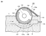
- FIG. 2 is a diagram showing a separator and a configuration around the separator in the water treatment apparatus according to the embodiment of the present invention. As shown in FIG. 2, the separator 130 includes a drum 131, a superconducting magnet 132, a scraper 133, and a magnetic shield 134.
- the drum 131 has a peripheral surface 131a.
- the peripheral surface 131a of the drum 131 is in contact with the water to be treated 1.
- the lower half portion of the drum 131 is arranged so as to be immersed in the water to be treated 1.
- the drum 131 is rotatable.
- a drive device 135 for rotating the drum 131 is provided at the center of the drum 131.
- the separator 130 further includes a separator tank 136 located below the drum 131 and in the processing tank 110.
- a separation path 137 is formed under the drum 131 by the separation tank 136.
- the water 1 to be treated that has flowed into the separation path 137 in the treatment tank 110 flows along the peripheral surface 131a of the drum 131 in the direction opposite to the rotation direction R of the drum 131.
- the water to be treated water discharge line 115 is connected to the separation tank 136, and the water to be treated 1 flowing through the separation path 137 is discharged from the water to be treated water discharge line 115.
- the superconducting magnet 132 is arranged inside the peripheral surface 131a along the rotation direction R of the drum 131.
- the superconducting magnet 132 magnetically magnetizes the magnetic powder-containing activated sludge 2 contained in the water to be treated 1 flowing through the separation path 137 on the peripheral surface 131a.
- details of the configuration of the superconducting magnet 132 will be described.
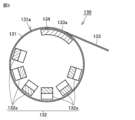
- FIG. 3 is a diagram showing a configuration of a separator in the water treatment apparatus according to the embodiment of the present invention.
- the superconducting magnet 132 is composed of one or more superconducting coils 132a, and specifically, is composed of an even number of superconducting coils 132a.
- An even number of superconducting coils 132a are arranged along the peripheral surface 131a.
- the polar orientation of each of the even number of superconducting coils 132a is along the radial direction of the drum 131.
- the polar directions of the adjacent superconducting coils 132a are different from each other in the radial direction.
- the direction of the polarity of the superconducting coil 132a can be controlled by the direction of the current applied to the superconducting coil 132a. Further, in the present embodiment, an even number of superconducting coils 132a are housed in a single cooling container.
- the superconducting coil 132a is formed by winding a superconducting wire and fixing and holding the superconducting wires with an adhesive such as epoxy resin or paraffin.
- the superconducting coil 132a generates a magnetic field for magnetizing the magnetic powder-containing activated sludge 2 on the peripheral surface 131a.
- a metal-based superconducting conductor made of NbTi (niobium-titanium) and copper can be used as the superconducting wire.
- the superconducting magnet 132 is formed of the high-temperature superconducting material.
- the cooling operation temperature of the superconducting coil 132a can be set higher than 4.2K, and the cooling efficiency of a refrigerator (not shown) for cooling the superconducting coil 132a is improved.
- the operating cost of the water treatment device 100 can be reduced.
- the cooling efficiency is improved by setting the operating temperature of the refrigerator high, and when the amount of water 1 to be treated temporarily increases due to heavy rain or the like, the operating temperature of the refrigerator is lowered to superconducting.
- the generated magnetic field is increased by lowering the cooling temperature of the coil 132a and increasing the energizing current of the superconducting coil 132a.
- the wastewater treatment capacity of the water treatment device 100 can be temporarily increased to cope with the increase in the amount of water to be treated 1.
- the superconducting coil 132a is operated in the permanent current mode by disconnecting the superconducting coil from the exciting power supply by using a permanent current switch (not shown) after the superconducting coil 132a is energized by connecting an exciting power source (not shown) and energizing the superconducting coil 132a. be able to. Since the exciting power supply is not connected to the superconducting coil 132a during the operation of the separator 130, the superconducting coil 132a does not immediately quench in the event of a trouble such as a power failure. Further, if the power failure is for a short time, the operation of the superconducting coil 132a can be continued as it is even after the power failure is resolved.
- the exciting power supply is not connected from the outside of the cooling container of the superconducting coil 132a during the operation of the separator 130, the amount of heat that enters the inside of the cooling container of the superconducting coil 132a from the portion connecting the superconducting coil 132a and the exciting power supply. Can be reduced.
- the superconducting coil 132a a race track-shaped superconducting coil having a length equivalent to the length of the drum 131 in the axial direction of the rotation axis of the drum 131 can be used.
- the magnetic powder-containing activated sludge 2 can be magnetized on the entire peripheral surface 131a in the axial direction of the rotation axis of the drum 131 without arranging a plurality of superconducting coils in the axial direction of the rotation axis of the drum 131.
- the water treatment device 100 can be easily assembled.
- the scraper 133 has a sliding contact portion 133a that is in sliding contact with the peripheral surface 131a.
- the sliding contact portion 133a is located above the water to be treated 1 stored in the treatment tank 110. That is, the peripheral surface 131a is in sliding contact with the sliding contact portion 133a at the portion exposed from the water to be treated 1.
- the scraper 133 can scrape the magnetic powder-containing activated sludge 2 magnetically attached to the peripheral surface 131a by the sliding contact portion 133a.
- the end of the scraper 133 on the side opposite to the sliding contact portion 133a side is in contact with the water 1 to be treated in the treatment tank 110.
- the magnetic powder-containing activated sludge 2 scraped from the peripheral surface 131a by the scraper 133 is transferred to the upper side of the scraper 133 and returned to the tank 110 to be treated.
- the magnetic shield 134 is arranged along the rotation direction R inside the peripheral surface 131a so as to face the sliding contact portion 133a via the peripheral surface 131a.
- the magnetic shield 134 is arranged at a position different from that of the superconducting magnet 132 in the rotation direction R.
- the magnetic shield 134 is arranged concentrically with the superconducting magnet 132 with respect to the center of the drum 131.
- the magnetic shield 134 is arranged at a position facing the superconducting magnet 132 with the center of the drum 131 interposed therebetween.
- the magnetic shield 134 is a superconductor. Further, the magnetic shield 134 is formed of a high-temperature superconducting material.
- the magnetic shield 134 composed of the superconductor shields the magnetic field that is generated by the superconducting magnet 132 and tries to pass through the magnetic shield 134 by utilizing the Meissner effect that the magnetic field lines cannot enter the inside of the superconductor.
- the magnetic shield 134 is used after being cooled to a critical temperature or lower and transferred to a superconducting state.
- the magnetic shield 134 is, for example, a superconductor formed by molding a metal-based superconductor, a bulk type superconductor, or a superconducting coil.
- the magnetic shield 134 is a bulk type superconductor
- the bulk type superconductor is formed by sintering fine particles of a ceramic superconductor at a high temperature such as 450 ° C. to 900 ° C.
- the magnetic shield 134 is a superconducting coil
- the magnetic shield 134 is a superconducting coil formed by winding a superconducting wire, and both ends are not short-circuited with each other.
- the superconducting coil is fixed and held by an adhesive such as epoxy resin or paraffin.
- a metal-based superconducting conductor made of NbTi (niobium titanium) and copper can be used as the superconducting wire material constituting the magnetic shield 134.
- the magnetic shield 134 shields the magnetic field generated by the superconducting magnet 132, the number of turns of the superconducting coils constituting the magnetic shield 134 is smaller than the number of turns of each of one or more superconducting coils 132a constituting the superconducting magnet 132.
- FIG. 4 is a diagram showing the configuration of the separator in the water treatment apparatus according to the embodiment of the present invention and the magnetic flux density distribution by the superconducting magnet in the separator in an overlapping manner.
- the magnitude of the magnetic flux density is shown by shading. That is, the darker the color, the higher the magnetic flux density, and the lighter the color, the lower the magnetic flux density.
- the magnetic flux density distribution by the superconducting magnet 132 in the present embodiment will be described by comparing with the magnetic flux density distribution in each of the comparative examples described below.
- FIG. 5 is a diagram showing a configuration of a separator in the water treatment apparatus according to Comparative Example 1.
- FIG. 6 is a diagram showing the configuration of the separator in the water treatment apparatus according to Comparative Example 1 and the magnetic flux density distribution by the superconducting magnet in the separator in an overlapping manner.
- the water treatment device according to Comparative Example 1 is different from the water treatment device 100 according to the embodiment of the present invention only in that the separator 730 does not include a magnetic shield.
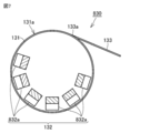
- FIG. 7 is a diagram showing a configuration of a separator in the water treatment apparatus according to Comparative Example 2.
- FIG. 8 is a diagram showing the configuration of the separator in the water treatment apparatus according to Comparative Example 2 and the magnetic flux density distribution by the superconducting magnet in the separator in an overlapping manner.
- the water treatment apparatus according to Comparative Example 2 is a Comparative Example only in that the polar directions of the adjacent superconducting coils 832a in the separator 830 are the same in the radial direction of the drum 131. It is different from the water treatment device according to 1.
- the magnetic flux density in the vicinity of the sliding contact portion 133a is smaller than that of Comparative Example 2. Therefore, it is easy to scrape off the magnetic powder-containing activated sludge 2 magnetically attached to the peripheral surface 131a of the drum 131.
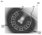
- FIG. 9 is a diagram showing a configuration of a separator in the water treatment apparatus according to Comparative Example 3.
- FIG. 10 is a diagram showing the configuration of the separator in the water treatment apparatus according to Comparative Example 3 and the magnetic flux density distribution by the superconducting magnet in the separator in an overlapping manner.
- the water treatment apparatus according to Comparative Example 3 is different from the water treatment apparatus according to Comparative Example 1 in that the superconducting magnet 932 is composed of an odd number of superconducting coils 932a in the separator 930. ..
- the superconducting magnet 132 is composed of an even number of superconducting coils 132a, it faces the superconducting magnet 132 with the center of the drum 131 interposed therebetween.
- a spot region S is formed at a position where the magnetic flux density is relatively small with respect to the periphery. Therefore, by arranging the sliding contact portion 133a of the scraper 133 in the vicinity of the spot region S, the magnetic force for magnetizing the magnetic powder-containing activated sludge 2 on the peripheral surface 131a of the drum 131 becomes small, and the circumference of the drum 131 becomes smaller.
- the magnetic powder-containing activated sludge 2 magnetically attached to the surface 131a can be easily scraped off.
- the superconducting magnet 932 is composed of an odd number of superconducting coils 932a instead of an even number, the spot region is not formed.
- the water treatment apparatus according to the comparative example 1 shown in FIGS. 5 and 6 can separate the magnetic powder-containing activated sludge 2 most efficiently.
- the spot region S where the magnetic flux density becomes small is located concentrically with the superconducting magnet 132 with respect to the center of the drum 131. That is, the spot region S is formed inside the drum 131 and does not overlap with the sliding contact portion 133a.
- the spot region S is located so as to overlap the sliding contact portion 133a.
- the magnetic shield 134 is arranged concentrically with the superconducting magnet 132 with respect to the center of the drum 131.
- the magnetic shield 134 is arranged at a position facing the superconducting magnet 132 with the center of the drum 131 interposed therebetween. That is, the magnetic shield 134 is arranged at the location where the spot region S is located in Comparative Example 1 shown in FIGS. 5 and 6.
- the spot region S moves outward in the radial direction of the drum 131 from the magnetic shield 134 so as to overlap the sliding contact portion 133a. To position.
- the separator 130 includes a drum 131, a superconducting magnet 132, a scraper 133, and a magnetic shield 134.
- the scraper 133 has a sliding contact portion 133a that is in sliding contact with the peripheral surface 131a.
- the magnetic shield 134 is a superconductor.
- the magnetic shield 134 is arranged along the rotation direction R inside the peripheral surface 131a so as to face the sliding contact portion 133a via the peripheral surface 131a.
- the magnetic shield 134 is arranged at a position different from that of the superconducting magnet 132 in the rotation direction R.
- the magnetic flux density at the sliding contact portion 133a becomes smaller due to the Meissner effect of the magnetic shield 134, so that the magnetic powder-containing activated sludge 2 magnetized on the peripheral surface 131a by the superconducting magnet 132 can be easily scraped off.
- the superconducting magnet 132 is composed of an even number of superconducting coils 132a.
- An even number of superconducting coils 132a are arranged along the peripheral surface 131a.
- the polar orientation of each of the even number of superconducting coils 132a is along the radial direction of the drum 131.
- the polar directions of the adjacent superconducting coils 132a are different from each other in the radial direction.
- the magnetic adhesion rate of the magnetic powder-containing activated sludge 2 on the peripheral surface 131a of the drum 131 is improved, and the purification efficiency of the water to be treated 1 can be improved.
- the magnetic powder-containing activated sludge 2 can be magnetized, so that the amount of magnetic powder charged into the water to be treated 1 is reduced. The cost can be reduced.
- the magnetic powder-containing activated sludge 2 can be more easily scraped off by the scraper 133.
- the volume of the magnetic shield 134 can be reduced, and the water treatment device 100 can be made inexpensive.
- the magnetic powder-containing activated sludge 2 can be easily scraped off, the wear of the scraper 133 and the peripheral surface 131a of the drum 131 can be reduced, and the maintenance cost can be reduced.
- the magnetic shield 134 is arranged concentrically with the superconducting magnet 132 with respect to the center of the drum 131.
- the magnetic shield 134 is arranged at a position facing the superconducting magnet 132 with the center of the drum 131 interposed therebetween.
- the magnetic shield 134 is, for example, a bulk type superconductor. As a result, the magnetic shield 134, which is a superconductor, can be formed into a desired shape.
- the magnetic shield 134 is, for example, a superconducting coil formed by winding a superconducting wire. As a result, the magnetic shield 134, which is a superconductor, can be manufactured at low cost.
- the superconducting magnet 132 is composed of one or more superconducting coils 132a.
- the number of turns of the superconducting coils constituting the magnetic shield 134 is less than the number of turns of each of one or more superconducting coils 132a constituting the superconducting magnet 132.
- the separator 130 using the superconducting magnet 132 can be manufactured at low cost.
- the superconducting magnet 132 and the magnetic shield 134 are formed of a high-temperature superconducting material. As a result, the cooling efficiency of the refrigerator that cools each of the superconducting magnet 132 and the magnetic shield 134 is improved, so that the operating cost of the water treatment device 100 can be reduced.
Landscapes
- Engineering & Computer Science (AREA)
- Chemical & Material Sciences (AREA)
- Power Engineering (AREA)
- Analytical Chemistry (AREA)
- Life Sciences & Earth Sciences (AREA)
- Hydrology & Water Resources (AREA)
- Environmental & Geological Engineering (AREA)
- Water Supply & Treatment (AREA)
- Organic Chemistry (AREA)
- Activated Sludge Processes (AREA)
- Treatment Of Sludge (AREA)
Abstract
水処理装置(100)は、処理槽(110)と、分離機(130)とを備えている。分離機(130)は、処理槽(110)内に位置し、被処理水(1)から磁性粉含有活性汚泥(2)を分離する。分離機(130)は、ドラム(131)と、超電導磁石(132)と、スクレーパ(133)と、磁気シールド(134)とを含んでいる。超電導磁石(132)は、磁性粉含有活性汚泥(2)を周面(131a)に磁着させる。スクレーパ(133)は、磁性粉含有活性汚泥(2)を掻き取り可能である。磁気シールド(134)は、超電導体である。磁気シールド(134)は、摺接部(133a)と周面(131a)を介して対向するように、周面(131a)の内側において回転方向(R)に沿って配置されている。磁気シールド(134)は、回転方向(R)において超電導磁石(132)とは異なる位置に配置されている。
Description
本発明は、水処理装置に関する。
水処理装置の構成を開示した文献として、特開2005-161161号公報(特許文献1)がある。特許文献1に記載された水処理装置は、磁気分離装置であって、活性汚泥懸濁液中の磁性粉含有活性汚泥を磁力によって液中から分離する。磁気分離装置は、磁気分離槽と、横型回転ドラムと、スクレーパーと、汚泥回収トラフと、架台と、駆動装置と、当該架台の下部に設けられた支持腕とを備えている。磁気分離槽は、活性汚泥懸濁液の流入部および流出部を有している。横型回転ドラムは、外周面に磁石が配置されている。スクレーパーは、該横型回転ドラムに付着した磁性粉含有活性汚泥を掻き落とす。
磁気により活性汚泥を分離する従来の水処理装置においては、分離機が、永久磁石のみにより磁性粉含有活性汚泥をドラムに磁着させる。永久磁石から発生する磁界の強さは比較的弱いため、分離機を大型化させた場合、磁性粉含有活性汚泥の磁着が不十分となる。
そこで、分離機の大型化のため、超電導磁石の強力な磁界で磁性粉含有活性汚泥を磁着させることが考えられる。しかし、超電導磁石を用いた場合、超電導磁石から発生する磁界の強さが非常に強いため、磁着させた磁性粉含有活性汚泥をスクレーパーで掻き取ることが困難となる。
本発明は上記課題に鑑みてなされたものであり、超電導磁石により磁着させた磁性粉含有活性汚泥を容易に掻き取ることができる、水処理装置を提供することを目的とする。
本発明に基づく水処理装置は、処理槽と、分離機とを備えている。処理槽は、磁性粉含有活性汚泥を含む被処理水が貯められている。分離機は、処理槽内に位置し、被処理水から磁性粉含有活性汚泥を分離する。分離機は、ドラムと、超電導磁石と、スクレーパと、磁気シールドとを含んでいる。ドラムは、周面を有している。ドラムは、周面が被処理水に接しつつ、回転可能である。超電導磁石は、周面の内側においてドラムの回転方向に沿って配置されている。超電導磁石は、磁性粉含有活性汚泥を周面に磁着させる。スクレーパは、周面と摺接する摺接部を有している。スクレーパは、磁性粉含有活性汚泥を掻き取り可能である。磁気シールドは、超電導体である。磁気シールドは、摺接部と周面を介して対向するように、周面の内側において回転方向に沿って配置されている。磁気シールドは、回転方向において超電導磁石とは異なる位置に配置されている。
本発明によれば、磁気シールドのマイスナー効果により、摺接部における磁束密度が小さくなるため、超電導磁石により周面に磁着させた磁性粉含有活性汚泥を容易に掻き取ることができる。
以下、本発明の一実施の形態に係る水処理装置について説明する。以下の実施の形態の説明においては、図中の同一または相当部分には同一符号を付して、その説明は繰り返さない。
図1は、本発明の一実施の形態に係る水処理装置の構成を示す概略図である。図1に示すように、本発明の一実施の形態に係る水処理装置100は、処理槽110と、磁性粉タンク120と、分離機130とを備えている。
処理槽110には、被処理水供給ライン111が接続されている。被処理水供給ライン111から、処理槽110に、下水または有機排水などの被処理水1が供給される。被処理水供給ライン111には、流量計112と有機物濃度測定器113とが配設されている。流量計112により、処理槽110に流入する被処理水1の流入量が測定される。有機物濃度測定器113により、処理槽110に流入する被処理水1の有機物濃度が測定される。
処理槽110には、浮遊物濃度測定器114が設けられている。浮遊物濃度測定器114により、処理槽110内の被処理水1中の活性汚泥浮遊物(MLSS:Mixed Liquor Suspended Solids)の濃度が測定される。なお、上記有機物濃度および上記活性汚泥浮遊物の濃度は、JIS K 0101(2017)に準拠する懸濁物質の分析方法により測定される。
処理槽110においては、被処理水1に含まれる有機物が、活性汚泥によって分解される。処理槽110において有機物が処理された被処理水1は、分離機130に送られる。分離機130において、活性汚泥と、浄化されて水質の向上した被処理水1とが、固液分離される。固液分離された被処理水1は、処理槽110に設けられた被処理水排出ライン115によって、処理槽110の外部へ排出される。分離方法の詳細については後述する。
処理槽110には、被処理水1の流入量を調整する調整槽、処理槽110へ流入する前の被処理水1に含まれる浮遊物を除去する沈澱池、処理槽110内の被処理水1に酸素を供給するための曝気手段、および、被処理水1を消毒するための消毒手段などが、適宜設置されてもよい。被処理水排出ライン115に、または、分離機130と被処理水排出ライン115との間に、沈殿槽を設けてもよい。当該沈殿槽においては、分離機130では被処理水1から除去しきれなかった固形物が沈殿し、分離される。
磁性粉タンク120からは、処理槽110内の被処理水1に磁性粉が添加される。磁性粉は、粉末状のままの状態で、あるいは、水などの分散媒に磁性粉を分散させた状態で、磁性粉タンク120から添加される。
上記磁性粉は、常磁性粉あるいは強磁性粉のいずれであってもよく、たとえば、酸化鉄、コバルト、酸化クロム、フェライトなどが挙げられる。処理槽110内の被処理水1においては、有機物の分解に伴い増殖した微生物を含む汚泥が、フロックを形成する。磁性粉は、この汚泥フロックによって形成される3次元構造体が有する孔、または、くぼみ等に入り込む。あるいは、磁性粉は、静電的な相互作用により、汚泥と結合する。このようにして、磁性粉含有活性汚泥2が形成される。すなわち、処理槽110においては、被処理水1内の有機物が微生物によって処理されるとともに、上記磁性粉含有活性汚泥を含む被処理水1が貯められている。
分離機130は、処理槽110内に位置し、被処理水1から磁性粉含有活性汚泥を分離する。図2は、本発明の一実施の形態に係る水処理装置における分離機および分離機周辺の構成を示す図である。図2に示すように、分離機130は、ドラム131と、超電導磁石132と、スクレーパ133と、磁気シールド134とを含んでいる。
ドラム131は、周面131aを有している。ドラム131は、周面131aが被処理水1に接している。本実施の形態においては、ドラム131の下半分の部分が、被処理水1に浸かるように配置されている。ドラム131は、回転可能である。ドラム131の中心部には、ドラム131を回転させる駆動装置135が設けられている。
分離機130は、ドラム131の下方に位置し、かつ、処理槽110内に位置する分離槽136をさらに含んでいる。分離槽136によって、ドラム131の下側に分離経路137が形成されている。処理槽110内において分離経路137内に流入した被処理水1は、ドラム131の周面131aに沿って、ドラム131の回転方向Rとは逆向きに流れる。被処理水排出ライン115は、分離槽136に接続されており、分離経路137を流れた被処理水1は、被処理水排出ライン115から排出される。
超電導磁石132は、周面131aの内側においてドラム131の回転方向Rに沿って配置されている。超電導磁石132は、分離経路137を流れる被処理水1に含まれている磁性粉含有活性汚泥2を周面131aに磁着させる。以下、超電導磁石132の構成の詳細について説明する。
図3は、本発明の一実施の形態に係る水処理装置における分離機の構成を示す図である。図3に示すように、超電導磁石132は、1以上の超電導コイル132aで構成されており、具体的には、偶数個の超電導コイル132aで構成されている。偶数個の超電導コイル132aは周面131aに沿って並んでいる。偶数個の超電導コイル132aの各々の極性の向きは、ドラム131の径方向に沿っている。隣接する超電導コイル132aの極性の向きは、径方向において互いに異なっている。超電導コイル132aの極性の向きは、超電導コイル132aに通電させる電流の向きにより制御することができる。また、本実施の形態においては、偶数個の超電導コイル132aが、単一の冷却容器に収納されている。
超電導コイル132aは、超電導線材が巻回され、エポキシ樹脂またはパラフィン等の接着剤で超電導線材同士が固定および保持されることによって、構成されている。超電導コイル132aは、磁性粉含有活性汚泥2を周面131aに磁着させるための磁場を発生させる。上記超電導線材としては、NbTi(ニオブチタン)および銅からなる金属系超電導導体を用いることができる。
このように、本実施の形態において、超電導磁石132は、高温超電導材料により形成されている。これにより、超電導コイル132aの冷却運転温度を4.2Kより高く設定でき、超電導コイル132aを冷却する図示しない冷凍機の冷却効率が向上する。これにより、水処理装置100の運転コストを低減することができる。また、通常時には、冷凍機の運転温度を高く設定することで冷却効率を向上させ、豪雨等により被処理水1の量が一時的に増加したときには、冷凍機の運転温度を低くすることで超電導コイル132aの冷却温度を低くし、かつ、超電導コイル132aの通電電流を増加させることで発生磁場を大きくする。これにより、一時的に水処理装置100の排水処理能力を増加させて、被処理水1の水量増加に対応することができる。
超電導コイル132aは、図示しない励磁電源を接続して超電導コイル132aに通電させて励磁が完了した後、図示しない永久電流スイッチを用いることで、超電導コイルを励磁電源から切り離して永久電流モードで運転することができる。分離機130の運転中は励磁電源が超電導コイル132aに接続されていないため、停電等のトラブルが発生した場合に、直ちに超電導コイル132aがクエンチすることがない。また、短時間の停電であれば、停電の解消後もそのまま超電導コイル132aの運転を継続することができる。さらに、分離機130の運転中は、超電導コイル132aの冷却容器の外部から励磁電源が接続されないため、超電導コイル132aと励磁電源とを接続する部分から超電導コイル132aの冷却容器の内部に浸入する熱量を低減できる。
本実施の形態においては、超電導コイル132aとして、ドラム131の回転軸の軸方向におけるドラム131の長さと同等の長さを有するレーストラック形状の超電導コイルを用いることができる。これにより、ドラム131の回転軸の軸方向において複数個の超電導コイルを並べることなく、ドラム131の回転軸の軸方向において周面131a全体に磁性粉含有活性汚泥2を磁着させることができる。ひいては、水処理装置100の組立が容易となる。
図2および図3に示すように、スクレーパ133は、周面131aと摺接する摺接部133aを有している。摺接部133aは、処理槽110に貯められた被処理水1より上方に位置している。すなわち、周面131aは、被処理水1から露出している部分において摺接部133aと摺接している。スクレーパ133は、摺接部133aによって、周面131aに磁着した磁性粉含有活性汚泥2を掻き取り可能である。
スクレーパ133の摺接部133a側とは反対側の端部は、処理槽110の被処理水1と接触している。スクレーパ133によって周面131aから掻き取られた磁性粉含有活性汚泥2は、スクレーパ133の上側で移送されて、被処理槽110内に戻される。
図2および図3に示すように、磁気シールド134は、摺接部133aと周面131aを介して対向するように、周面131aの内側において回転方向Rに沿って配置されている。磁気シールド134は、回転方向Rにおいて超電導磁石132とは異なる位置に配置されている。磁気シールド134は、ドラム131の中心に対して超電導磁石132と同心円上に配置されている。磁気シールド134は、ドラム131の中心を挟んで超電導磁石132と対向する位置に配置されている。
磁気シールド134は、超電導体である。また、磁気シールド134は、高温超電導材料により形成されている。超電導体で構成された磁気シールド134は、磁力線が超電導体の内部に入り込めないというマイスナー効果を利用して、超電導磁石132によって発生した、磁気シールド134を透過しようとする磁場をシールドする。磁気シールド134は、臨界温度以下に冷却して超電導状態に転移させて用いられる。
磁気シールド134は、たとえば、金属系超伝導体を成形した超電導体、バルク型超電導体、または、超電導コイルである。磁気シールド134がバルク型超電導体である場合、当該バルク型超電導体は、セラミック系超電導体の微細粒子をたとえば450℃から900℃などの高温で焼結して成形される。
磁気シールド134が超電導コイルである場合、磁気シールド134は、超電導線材を巻回して形成された超電導コイルであって、両端が互いに短絡されていない解放コイルである。当該超電導コイルは、エポキシ樹脂またはパラフィン等の接着剤で固定および保持される。磁気シールド134を構成する超電導線材には、NbTi(ニオブチタン)および銅からなる金属系超電導導体を用いることができる。また、磁気シールド134によって超電導磁石132により発生する磁場をシールドするため、磁気シールド134を構成する超電導コイルの巻数は、超電導磁石132を構成する1以上の超電導コイル132aの各々の巻数より少ない。
図4は、本発明の一実施の形態に係る水処理装置における分離機の構成と、分離機内の超電導磁石による磁束密度分布とを重ねて示す図である。図4においては、磁束密度の大きさが濃淡で示されている。すなわち、色が濃いほど磁束密度が大きく、色が薄いほど磁束密度が小さい。本実施の形態における超電導磁石132による磁束密度分布については、以下に説明する各比較例における磁束密度分布と比較することで説明する。
図5は、比較例1に係る水処理装置における分離機の構成を示す図である。図6は、比較例1に係る水処理装置における分離機の構成と、分離機内の超電導磁石による磁束密度分布とを重ねて示す図である。
図5に示すように、比較例1に係る水処理装置は、分離機730が磁気シールドを含んでいない点でのみ、本発明の一実施の形態に係る水処理装置100と異なっている。
図7は、比較例2に係る水処理装置における分離機の構成を示す図である。図8は、比較例2に係る水処理装置における分離機の構成と、分離機内の超電導磁石による磁束密度分布とを重ねて示す図である。
図7に示すように、比較例2に係る水処理装置は、分離機830において隣接する超電導コイル832aの各々の極性の向きが、ドラム131の径方向において互いに同一である点でのみ、比較例1に係る水処理装置と異なっている。
図6および図8に示すように、比較例1における分離機730においては、隣接する超電導コイル132aの各々の極性の向きが、ドラム131の径方向において互いに異なっているため、比較例2における分離機830と比較して、周面131aを挟んで超電導磁石132とは反対側の領域、磁束密度が大きくなり、かつ、磁場勾配も大きくなっている。このため、比較例1においては、比較例2と比較して、図2に示す分離経路137において磁性粉含有活性汚泥2を周面131aに磁着させる磁気力が大きくなり、磁着率が向上する。また、比較例1における分離機730においては、比較例2と比較して、摺接部133a付近の磁束密度が小さくなっている。このため、ドラム131の周面131aに磁着した磁性粉含有活性汚泥2を掻き取りやすくなっている。
図9は、比較例3に係る水処理装置における分離機の構成を示す図である。図10は、比較例3に係る水処理装置における分離機の構成と、分離機内の超電導磁石による磁束密度分布とを重ねて示す図である。
図9に示すように、比較例3に係る水処理装置は、分離機930において、超電導磁石932が奇数個の超電導コイル932aで構成されている点で、比較例1に係る水処理装置と異なる。
図6および図10に示すように、比較例1における分離機730においては、超電導磁石132が偶数個の超電導コイル132aで構成されているため、ドラムの131の中心を挟んで超電導磁石132と対向する位置に、磁束密度が周辺に対して相対的に小さくなるスポット領域Sが形成される。このため、スクレーパ133の摺接部133aを上記のスポット領域S付近に配置することにより、磁性粉含有活性汚泥2をドラム131の周面131aに磁着させる磁気力が小さくなり、ドラム131の周面131aに磁着した磁性粉含有活性汚泥2を掻き取りやすくなる。一方、比較例3においては、超電導磁石932が、偶数個ではなく奇数個の超電導コイル932aで構成されているため、スポット領域は形成されていない。
このように、各比較例のうち、図5および図6に示す比較例1に係る水処理装置が最も効率よく磁性粉含有活性汚泥2を分離できる。しかしながら、図6に示すように、磁束密度が小さくなるスポット領域Sは、ドラム131の中心に対して超電導磁石132と同心円状に位置している。すなわち、スポット領域Sは、ドラム131の内部に形成され、摺接部133aと重なっていない。
ここで、図4に示すように、本発明の一実施の形態に係る水処理装置100においては、スポット領域Sが、摺接部133aと重なるように位置している。
図3および図4に示すように、本発明の一実施の形態に係る水処理装置100においては、磁気シールド134が、ドラム131の中心に対して超電導磁石132と同心円上に配置されている。磁気シールド134は、ドラム131の中心を挟んで超電導磁石132と対向する位置に配置されている。すなわち、図5および図6に示す比較例1においてスポット領域Sが位置している場所に、磁気シールド134が配置されている。図4に示すように、マイスナー効果によって磁気シールド134内には磁束が侵入できないため、スポット領域Sは、磁気シールド134よりドラム131の径方向外側に移動して、摺接部133aと重なるように位置する。これにより、磁性粉含有活性汚泥2をスクレーパ133の摺接部133aでさらに掻き落とし易くなる。また、スクレーパ133の摺接部133aおよびドラム131の周面131aの摩耗を軽減することができるとともに、保守コストを削減できる。
上記のように、本発明の一実施の形態に係る水処理装置100においては、分離機130が、ドラム131と、超電導磁石132と、スクレーパ133と、磁気シールド134とを含んでいる。スクレーパ133は、周面131aと摺接する摺接部133aを有している。磁気シールド134は、超電導体である。磁気シールド134は、摺接部133aと周面131aを介して対向するように、周面131aの内側において回転方向Rに沿って配置されている。磁気シールド134は、回転方向Rにおいて超電導磁石132とは異なる位置に配置されている。
これにより、磁気シールド134のマイスナー効果によって、摺接部133aにおける磁束密度が小さくなるため、超電導磁石132により周面131aに磁着させた磁性粉含有活性汚泥2を容易に掻き取ることができる。
超電導磁石132は、偶数個の超電導コイル132aで構成されている。偶数個の超電導コイル132aは周面131aに沿って並んでいる。偶数個の超電導コイル132aの各々の極性の向きは、ドラム131の径方向に沿っている。隣接する超電導コイル132aの極性の向きは、径方向において互いに異なっている。
これにより、ドラム131の周面131aへの磁性粉含有活性汚泥2の磁着率が向上し、被処理水1の浄化効率を向上できる。また、磁性粉含有活性汚泥2中の磁性粉量が比較的少ない場合においても、磁性粉含有活性汚泥2を磁着させることができるため、被処理水1に投入する磁性粉量を少なくしてコストを低減できる。さらに、磁性粉含有活性汚泥2を、スクレーパ133でさらに掻き取り易くなる。ひいては、磁気シールド134の体積を小さくすることができ、水処理装置100を廉価にすることができる。また、磁性粉含有活性汚泥2が掻き取りやすくなることで、スクレーパ133とドラム131の周面131aの摩耗を軽減することができ、保守コストを削減できる。
磁気シールド134は、ドラム131の中心に対して超電導磁石132と同心円上に配置されている。磁気シールド134は、ドラム131の中心を挟んで超電導磁石132と対向する位置に配置されている。これにより、磁束密度が相対的に低い領域にスクレーパ133の摺接部133aが位置するため、磁性粉含有活性汚泥2をスクレーパ133で容易に掻き取ることができる。
磁気シールド134は、たとえば、バルク型超電導体である。これにより、超電導体である磁気シールド134を所望の形状に成形することがきる。
磁気シールド134は、たとえば、超電導線材を巻回して形成された超電導コイルである。これにより、超電導体である磁気シールド134を廉価に製造することができる。
超電導磁石132は、1以上の超電導コイル132aで構成されている。磁気シールド134を構成する超電導コイルの巻数は、超電導磁石132を構成する1以上の超電導コイル132aの各々の巻数より少ない。これにより、超電導磁石132を用いた分離機130を廉価に製造することができる。
超電導磁石132および磁気シールド134は、高温超電導材料により形成される。これにより、超電導磁石132および磁気シールド134の各々を冷却する冷凍機の冷却効率が向上するため、水処理装置100の運転コストを低減することができる。
なお、今回開示した上記実施の形態はすべての点で例示であって、限定的な解釈の根拠となるものではない。したがって、本発明の技術的範囲は、上記した実施の形態のみによって解釈されるものではなく、請求の範囲の記載に基づいて画定される。また、請求の範囲と均等の意味および範囲内でのすべての変更が含まれる。
1 被処理水、2 磁性粉含有活性汚泥、100 水処理装置、110 処理槽、111 被処理水供給ライン、112 流量計、113 有機物濃度測定器、114 浮遊物濃度測定器、115 被処理水排出ライン、120 磁性粉タンク、130,730,830,930 分離機、131 ドラム、131a 周面、132,932 超電導磁石、132a,832a,932a 超電導コイル、133 スクレーパ、133a 摺接部、134 磁気シールド、135 駆動装置、136 分離槽、137 分離経路、R 回転方向、S スポット領域。
Claims (7)
- 磁性粉含有活性汚泥を含む被処理水が貯められた処理槽と、
前記処理槽内に位置し、前記被処理水から前記磁性粉含有活性汚泥を分離する分離機とを備え、
前記分離機は、
周面を有し、該周面が前記被処理水に接しつつ、回転可能なドラムと、
前記周面の内側において前記ドラムの回転方向に沿って配置され、前記磁性粉含有活性汚泥を前記周面に磁着させる超電導磁石と、
前記周面と摺接する摺接部を有し、前記磁性粉含有活性汚泥を掻き取り可能なスクレーパと、
前記摺接部と前記周面を介して対向するように、前記周面の内側において前記回転方向に沿って配置され、かつ、前記回転方向において前記超電導磁石とは異なる位置に配置された超電導体の磁気シールドとを含む、水処理装置。 - 前記超電導磁石は、偶数個の超電導コイルで構成されており、
前記偶数個の超電導コイルは前記周面に沿って並び、
前記偶数個の超電導コイルの各々の極性の向きは、前記ドラムの径方向に沿っており、かつ、隣接する超電導コイルの極性の向きは、前記径方向において互いに異なっている、請求項1に記載の水処理装置。 - 前記磁気シールドは、前記ドラムの中心に対して前記超電導磁石と同心円上に配置され、かつ、前記ドラムの前記中心を挟んで前記超電導磁石と対向する位置に配置される、請求項1または請求項2に記載の水処理装置。
- 前記磁気シールドは、バルク型超電導体である、請求項1から請求項3のいずれか1項に記載の水処理装置。
- 前記磁気シールドは、超電導線材を巻回して形成された超電導コイルである、請求項1から請求項3のいずれか1項に記載の水処理装置。
- 前記超電導磁石は、1以上の超電導コイルで構成されており、
前記磁気シールドを構成する超電導コイルの巻数が、前記超電導磁石を構成する1以上の超電導コイルの各々の巻数より少ない、請求項5に記載の水処理装置。 - 前記超電導磁石および前記磁気シールドは、高温超電導材料により形成される、請求項1から請求項3のいずれか1項に記載の水処理装置。
Priority Applications (2)
| Application Number | Priority Date | Filing Date | Title |
|---|---|---|---|
| PCT/JP2019/030688 WO2021024349A1 (ja) | 2019-08-05 | 2019-08-05 | 水処理装置 |
| JP2021538564A JP7077490B2 (ja) | 2019-08-05 | 2019-08-05 | 水処理装置 |
Applications Claiming Priority (1)
| Application Number | Priority Date | Filing Date | Title |
|---|---|---|---|
| PCT/JP2019/030688 WO2021024349A1 (ja) | 2019-08-05 | 2019-08-05 | 水処理装置 |
Publications (1)
| Publication Number | Publication Date |
|---|---|
| WO2021024349A1 true WO2021024349A1 (ja) | 2021-02-11 |
Family
ID=74502550
Family Applications (1)
| Application Number | Title | Priority Date | Filing Date |
|---|---|---|---|
| PCT/JP2019/030688 Ceased WO2021024349A1 (ja) | 2019-08-05 | 2019-08-05 | 水処理装置 |
Country Status (2)
| Country | Link |
|---|---|
| JP (1) | JP7077490B2 (ja) |
| WO (1) | WO2021024349A1 (ja) |
Citations (5)
| Publication number | Priority date | Publication date | Assignee | Title |
|---|---|---|---|---|
| JPH08168790A (ja) * | 1994-10-17 | 1996-07-02 | Ishikawajima Harima Heavy Ind Co Ltd | 活性汚泥の磁気分離装置 |
| JPH09150180A (ja) * | 1995-12-01 | 1997-06-10 | Ishikawajima Harima Heavy Ind Co Ltd | 活性汚泥回収装置及び活性汚泥回収方法 |
| JPH09253683A (ja) * | 1996-03-25 | 1997-09-30 | Ishikawajima Harima Heavy Ind Co Ltd | 活性汚泥の磁気分離装置 |
| JP2000000573A (ja) * | 1998-06-15 | 2000-01-07 | Mitsubishi Electric Corp | 浄化装置 |
| JP2005125228A (ja) * | 2003-10-23 | 2005-05-19 | Yasukura Sakai | 有機排水の処理方法及び処理装置 |
Family Cites Families (2)
| Publication number | Priority date | Publication date | Assignee | Title |
|---|---|---|---|---|
| JP2005125249A (ja) * | 2003-10-24 | 2005-05-19 | Yasukura Sakai | 汚泥処理装置 |
| JP2013052374A (ja) * | 2011-09-06 | 2013-03-21 | Toyobo Co Ltd | 磁気分離用布帛及び磁気分離装置 |
-
2019
- 2019-08-05 JP JP2021538564A patent/JP7077490B2/ja not_active Expired - Fee Related
- 2019-08-05 WO PCT/JP2019/030688 patent/WO2021024349A1/ja not_active Ceased
Patent Citations (5)
| Publication number | Priority date | Publication date | Assignee | Title |
|---|---|---|---|---|
| JPH08168790A (ja) * | 1994-10-17 | 1996-07-02 | Ishikawajima Harima Heavy Ind Co Ltd | 活性汚泥の磁気分離装置 |
| JPH09150180A (ja) * | 1995-12-01 | 1997-06-10 | Ishikawajima Harima Heavy Ind Co Ltd | 活性汚泥回収装置及び活性汚泥回収方法 |
| JPH09253683A (ja) * | 1996-03-25 | 1997-09-30 | Ishikawajima Harima Heavy Ind Co Ltd | 活性汚泥の磁気分離装置 |
| JP2000000573A (ja) * | 1998-06-15 | 2000-01-07 | Mitsubishi Electric Corp | 浄化装置 |
| JP2005125228A (ja) * | 2003-10-23 | 2005-05-19 | Yasukura Sakai | 有機排水の処理方法及び処理装置 |
Also Published As
| Publication number | Publication date |
|---|---|
| JPWO2021024349A1 (ja) | 2021-11-04 |
| JP7077490B2 (ja) | 2022-05-30 |
Similar Documents
| Publication | Publication Date | Title |
|---|---|---|
| US5944986A (en) | Liquid purification apparatus | |
| US20090152176A1 (en) | Magnetic separation of fine particles from compositions | |
| JP5044403B2 (ja) | 純化装置および純化方法 | |
| JP7077490B2 (ja) | 水処理装置 | |
| JP2001314777A (ja) | 磁気固液分離装置 | |
| CN108380383B (zh) | 一种水平磁场立环高梯度磁选机 | |
| JP2005161161A (ja) | 排水処理装置及び磁気分離装置 | |
| JP2002066375A (ja) | 被除去物の磁気分離装置 | |
| US10875033B2 (en) | Removal of ferromagnetic material from a fluid stream | |
| CN113969182B (zh) | 一种催化裂化油浆中固体颗粒的分离装置及方法 | |
| JPH09117618A (ja) | 浄化装置 | |
| CN219092349U (zh) | 一种废水处理用高梯度磁选分离机及其复合磁系 | |
| RU2203124C1 (ru) | Высокоградиентный магнитный фильтр | |
| JP4288555B2 (ja) | 磁性体を用いた分離浄化装置 | |
| JP3799390B2 (ja) | 磁性体を用いた浄化装置 | |
| JP4179513B2 (ja) | 液体処理装置 | |
| JP3580117B2 (ja) | 磁気分離装置 | |
| JP2023149672A (ja) | 磁気分離装置及び磁気分離方法 | |
| JP3463254B2 (ja) | 磁気分離装置 | |
| JP2007098297A (ja) | 飲料水用浄水システム | |
| JP2005111342A (ja) | 汚泥処理装置 | |
| JPH10118518A (ja) | 磁気分離浄化装置 | |
| RU2360740C1 (ru) | Высокоградиентный магнитный фильтр | |
| CN212740830U (zh) | 一种超磁智能净化装置 | |
| JP2008094660A (ja) | 石炭灰による人工ゼオライト製造方法およびその装置 |
Legal Events
| Date | Code | Title | Description |
|---|---|---|---|
| 121 | Ep: the epo has been informed by wipo that ep was designated in this application |
Ref document number: 19940804 Country of ref document: EP Kind code of ref document: A1 |
|
| ENP | Entry into the national phase |
Ref document number: 2021538564 Country of ref document: JP Kind code of ref document: A |
|
| NENP | Non-entry into the national phase |
Ref country code: DE |
|
| 122 | Ep: pct application non-entry in european phase |
Ref document number: 19940804 Country of ref document: EP Kind code of ref document: A1 |