WO2021020466A1 - 眼底撮影装置 - Google Patents
眼底撮影装置 Download PDFInfo
- Publication number
- WO2021020466A1 WO2021020466A1 PCT/JP2020/029130 JP2020029130W WO2021020466A1 WO 2021020466 A1 WO2021020466 A1 WO 2021020466A1 JP 2020029130 W JP2020029130 W JP 2020029130W WO 2021020466 A1 WO2021020466 A1 WO 2021020466A1
- Authority
- WO
- WIPO (PCT)
- Prior art keywords
- light
- fundus
- green
- light source
- red
- Prior art date
- Legal status (The legal status is an assumption and is not a legal conclusion. Google has not performed a legal analysis and makes no representation as to the accuracy of the status listed.)
- Ceased
Links
Images




Classifications
-
- A—HUMAN NECESSITIES
- A61—MEDICAL OR VETERINARY SCIENCE; HYGIENE
- A61B—DIAGNOSIS; SURGERY; IDENTIFICATION
- A61B3/00—Apparatus for testing the eyes; Instruments for examining the eyes
- A61B3/10—Objective types, i.e. instruments for examining the eyes independent of the patients' perceptions or reactions
-
- A—HUMAN NECESSITIES
- A61—MEDICAL OR VETERINARY SCIENCE; HYGIENE
- A61B—DIAGNOSIS; SURGERY; IDENTIFICATION
- A61B3/00—Apparatus for testing the eyes; Instruments for examining the eyes
- A61B3/10—Objective types, i.e. instruments for examining the eyes independent of the patients' perceptions or reactions
- A61B3/12—Objective types, i.e. instruments for examining the eyes independent of the patients' perceptions or reactions for looking at the eye fundus, e.g. ophthalmoscopes
Definitions
- the present invention relates to a fundus photography apparatus that irradiates the fundus with light, receives the reflected light from the fundus, and photographs the fundus.
- the fundus imaging device irradiates the fundus with red, green, and blue lights to perform imaging, and obtains a color fundus image.
- a color fundus image For example, in Patent Document 1, laser light emitted from a semiconductor laser light source that emits red, green, and blue laser light is reflected by a dichroic mirror, and the fundus of the eye to be inspected is scanned two-dimensionally using a polygon mirror and a galvano mirror.
- a fundus imaging apparatus that causes a light receiving element to receive light reflected from the fundus and forms a fundus image of the eye to be inspected based on the received signal.
- the color fundus image obtained by the fundus camera is read by an ophthalmologist, and by observing the state of the retinal tissue and blood vessels to confirm the presence or absence of bleeding or white spots from the blood vessels, it is useful for appropriate diagnosis.
- the present invention has been made in view of such a point, and an object of the present invention is to provide a fundus photography apparatus capable of taking a fundus image having a high contrast of a blood vessel image.
- the present invention emits red light from a red light source, green light from a green light source, and blue light from a blue light source, and projects the light onto the fundus of the eye to be examined, and reflects the light from the fundus.
- a fundus imaging device that receives light and photographs the fundus, wherein the wavelength of the green light is set based on the ratio of the absorbance of hemoglobin to the absorbance of melanin.
- the inventors of the present application considered that it is very important to select the central wavelengths of red, green, and blue of the illumination light in order to clearly depict the blood vessel image in the fundus image by the color composite image.
- the difference between the color of the retinal tissue and the color of the blood vessel is clarified on the assumption that the color of the retinal tissue is represented by the color of melanin and the color of the blood vessel is represented by the color of hemoglobin. It was found that the contrast of the blood vessel image in the fundus image can be enhanced by selecting the central wavelength of the illumination light.
- the color of retinal tissue is set by setting the wavelength of green light based on the ratio of the absorbance of hemoglobin representing the color of blood vessels to the absorbance of melanin representing the color of retinal tissue.
- the difference between the color of the blood vessel and the color of the blood vessel becomes clear, and it becomes possible to take an image of the fundus of the eye with high contrast of the blood vessel image.
- the wavelength of the green light is set in the vicinity of the wavelength at which the value of the absorbance of hemoglobin / the absorbance of melanin peaks (Invention 2).
- the peak wavelength of the green light is in the range of 548 nm to 565 nm (Invention 3).
- the peak wavelength of the red light and the peak wavelength of the blue light are separated from the peak wavelength of the green light by 50 nm or more (Invention 4).
- the peak wavelength of the green light is 560 nm ⁇ 5 nm
- the peak wavelength of the blue light is 490 nm ⁇ 20 nm
- the peak wavelength of the red light is 650 nm ⁇ 30 nm. Is preferable (Invention 5).
- the red light, the green light, and the blue light are all monochromatic light (Invention 6).
- the amount of red light is larger than the amount of green light and blue light (Invention 7).
- the fundus imaging device of the present invention it is possible to capture a fundus image having a high contrast of a blood vessel image.
- FIG. 1 illustrates the optical configuration of the fundus photography apparatus according to the embodiment of the present invention.
- the measurement light emitted from the light source unit 1 is incident on the central reflection mirror 2, and the subject to be measured by the central reflection mirror 2.
- the measurement light whose direction is changed in the optometry direction is incident on the first scanning device 3.
- the first scanning device 3 is a scanning device for scanning in the lateral direction (horizontal direction), and the scanned measurement light is incident on the second scanning device 5 via the scanning relay lens system 4.
- the second scanning device 5 is a scanning device for scanning in the vertical direction (direction orthogonal to the scanning direction of the first scanning device 3), and the two scanning devices of the first scanning device 3 and the second scanning device 5 are used.
- the measurement light can scan the fundus of the eye to be examined two-dimensionally.
- the measurement light scanned by the second scanning device 5 enters the eye E to be inspected through the objective lens system 6, passes through the pupil of the eye E to be inspected, and is focused on the fundus Ef.
- the measurement light projected onto the fundus Ef is reflected by the fundus Ef, and the reflected light from the fundus Ef travels in the same optical path in the opposite direction, and the objective lens system 6, the second scanning device 5, and the scanning relay lens system 4
- the light enters the central reflection mirror 2 via the first scanning device 3, passes through the opening of the central reflection mirror 2, and enters the light receiving system 7 (light receiving optical system).
- the configuration from the central reflection mirror 2 to the eye E to be inspected is the objective optical system of the fundus imaging device according to the present embodiment, and the light source of the measurement light emitted from the light source unit 1 and the light received from the fundus Ef. It becomes a common optical path of the optical path.
- the fundus photography device has a control unit (not shown) to which each component device of the fundus photography device is connected, and the control unit performs various controls of the fundus photography device.
- the light source unit 1 includes four light sources: a red laser light source 11 that emits red light, a green laser light source 12 that emits green light, a blue laser light source 13 that emits blue light, and a near infrared laser light source 14 that emits near infrared light. It includes three mirrors, a first dichroic mirror 15, a second dichroic mirror 16, and a third dichroic mirror 17. The red light emitted from the red laser light source 11 passes through the first dichroic mirror 15, the second dichroic mirror 16 and the third dichroic mirror 17 and is incident on the central reflection mirror 2, and the green light emitted from the green laser light source 12.
- the near-infrared light emitted from the near-infrared laser light source 14 is reflected by the third dichroic mirror 17 and incident on the central reflection mirror 2 after being reflected by the third dichroic mirror 17. It is incident on 2.
- the near-infrared light is used in the continuous shooting mode described later, and the visible light red light, green light and blue light are used in the color image shooting mode described later.
- the first scanning device 3 is composed of a polygon mirror, and is rotationally driven by a driving means (not shown) connected to the first scanning device 3 and the control unit to scan the measurement light at high speed in the lateral direction (horizontal direction). Then, it is incident on the scanning relay lens system 4.
- the polygon mirror 3 which is the first scanning device 3 is driven by the driving means so as to perform continuous scanning 6600 times per second, for example.
- the scanning relay lens system 4 relays the measurement light laterally scanned by the first scanning device 3 to the second scanning device 5, and the scanned measurement light is focused on the second scanning device 5.
- the second scanning device 5 is composed of a galvano mirror, and is reciprocally driven by a driving means (not shown) connected to the second scanning device 5 and the control unit, so that the measurement light is transmitted in the vertical direction (of the first scanning device 3). It is scanned at a low speed in a direction orthogonal to the scanning direction) and incident on the objective lens system 6.
- the galvanometer mirror 5, which is the second scanning device 5, is driven by a driving means so as to perform scanning 15 times per second in the continuous shooting mode and scan once every 0.5 seconds in the color image shooting mode, for example. To.
- the objective lens system 6 relays the measurement light scanned in the vertical direction by the second scanning device 5 to the pupil of the eye E to be inspected, and the scanned measurement light is focused on the pupil of the eye E to be inspected. The light is projected onto the fundus Ef.
- the light receiving system 7 includes a red light receiving sensor 71 having a light receiving element that receives red light, a green light receiving sensor 72 having a light receiving element that receives green light, a blue light receiving sensor 73 having a light receiving element that receives blue light, and the like. It includes four sensors of the near-infrared light receiving sensor 74 provided with a light receiving element for receiving near infrared light, and three mirrors of the fourth dichroic mirror 75, the fifth dichroic mirror 76, and the sixth dichroic mirror 77. A condensing lens and a light receiving pinhole are arranged on the light receiving paths of the red light receiving sensor 71, the green light receiving sensor 72, the blue light receiving sensor 73, and the near infrared light receiving sensor 74, respectively.
- the near-infrared light receiving sensor 74 is composed of a filter that cuts a wavelength band other than near-infrared light and a light-receiving element (photodiode), thereby receiving luminance information at each point of the fundus Ef. It can be obtained by the sensor 74.
- a photographed image of the fundus Ef can be formed based on the obtained luminance information (output intensity of the near-infrared light receiving sensor 74) and the scanning position information of the first scanning device 3 and the second scanning device 5. it can.
- the photographed image data of the fundus Ef is stored in a storage device (not shown) connected to the control unit, displayed on a monitor (not shown), or printed by a printer (not shown).
- a part (blue) of the reflected light from the fundus Ef incident on the light receiving system 7 is transmitted by the fourth dichroic mirror 75 and then reflected by the fifth dichroic mirror 76, and the condensing lens 73a Is guided to the light receiving pin hole 73b, and the reflected light that has passed through the light receiving pin hole 73b is incident on the blue light receiving sensor 73.
- a part (green) of the reflected light passes through the 4th dichroic mirror 75 and the 5th dichroic mirror 76, is reflected by the 6th dichroic mirror 77, is guided to the light receiving pinhole 72b by the condenser lens 72a, and receives light.
- the reflected light that has passed through the pinhole 72b is incident on the green light receiving sensor 72. Further, a part of the reflected light (red) is transmitted through the 4th dichroic mirror 75, the 5th dichroic mirror 76 and the 6th dichroic mirror 77, and is guided to the light receiving pin hole 71b by the condenser lens 71a to pass the light receiving pin hole 71b.
- the passed reflected light is incident on the red light receiving sensor 71.
- the red light receiving sensor 71, the green light receiving sensor 72, and the blue light receiving sensor 73 are composed of a filter and a light receiving element (photodiode) that cut a wavelength band other than the light to be received, and thereby, respectively, of the fundus Ef.
- the brightness information of each point can be obtained by each sensor. Then, based on the obtained brightness information (output intensity of each sensor) and the scanning position information of the first scanning device 3 and the second scanning device 5, a photographed image of the fundus Ef can be formed, and red light is received.
- the red captured image data obtained by the sensor 71, the green captured image data obtained by the green light receiving sensor 72, and the blue captured image data obtained by the blue light receiving sensor 73 are combined and subjected to gamma processing or the like to perform a color fundus image. Data can be generated.
- each light receiving sensor can be configured without providing the filter that cuts the wavelength band described above.
- each light receiving pinhole 71b, 72b, 73b, 74b is arranged at a position conjugate with the fundus Ef of the eye E to be inspected.
- the light (stray light) unnecessary for measurement generated at a portion away from the fundus of the eye is the light receiving pinholes 71b, 72b, 73b, It is removed in 74b, and a high-contrast fundus image can be taken.
- the fundus photography device has a continuous shooting mode in which a fundus image is taken by near-infrared light and a color in which a color fundus image is taken by visible light such as red light, green light and blue light. It is configured so that it can be switched between the image shooting mode.
- near-infrared light is emitted from the near-infrared laser light source 14 while the first scanning device 3 (polygon mirror) and the second scanning device 5 (galvano mirror) are continuously scanning, and the near infrared light is emitted.
- the image of the fundus of the eye is displayed live on a monitor (not shown) connected to the control unit. Alignment and focus adjustment of the fundus image are performed using this continuous imaging mode using near-infrared light.
- the shooting button (not shown) to switch from continuous shooting mode to color image shooting mode.
- red light, green light, and blue light are simultaneously illuminated on the fundus of the eye, and the reflected light of each color is simultaneously received and photographed, and the obtained red photograph image data, green photograph image data, and blue photograph image data are taken.
- the color fundus image data is generated by synthesizing the images.
- the continuous scanning of the galvano mirror 5 is temporarily stopped, and the galvano mirror 5 moves to the shooting start position. Then, the near-infrared laser light source 14 is turned off, the red laser light source 11, the green laser light source 12, and the blue laser light source 13 are turned on at the same time, and the galvano mirror 5 starts moving again to start taking a color fundus image.
- image data of 3000 ⁇ 3000 is acquired simultaneously for each of red light, green light, and blue light by vertical scanning for 0.5 seconds.
- the obtained red fundus image data, green fundus image data, and blue fundus image data are combined and subjected to gamma processing or the like to generate color fundus image data.
- the generated color fundus image data is stored in a storage device (not shown) and displayed on a monitor (not shown).
- the red laser light source 11, the green laser light source 12, and the blue laser light source 13 are turned off, and the infrared fundus observation image is returned to the live display state on the monitor (not shown).
- the peak wavelength of red light emitted from the red laser light source 11 is 650 nm
- the peak wavelength of green light emitted from the green laser light source 12 is 560 nm
- the peak wavelength of blue light emitted from the blue laser light source 13 is 560 nm.
- the peak wavelength of the near-infrared light emitted from the near-infrared laser light source 14 is set to 780 nm. The method of setting the peak wavelength of the light emitted from each laser light source will be described in detail below.
- the inventors of the present application considered that it is very important to select the central wavelengths of red, green, and blue of the illumination light in order to clearly depict the blood vessel image in the fundus image by the color composite image.
- the difference between the color of the retinal tissue and the color of the blood vessel is clarified on the assumption that the color of the retinal tissue is represented by the color of melanin and the color of the blood vessel is represented by the color of hemoglobin. It was found that the contrast of the blood vessel image in the fundus image can be enhanced by selecting the central wavelength of the illumination light.
- FIG. 2 shows a graph showing the absorption wavelength distribution of melanin and hemoglobin.
- the vertical axis is the absorbance (common logarithm), and the horizontal axis is the wavelength.
- FIG. 3 is a graph showing the value of the absorbance of hemoglobin / the absorbance of melanin, that is, a graph for observing the ratio of light and darkness of blood to retinal pigment.
- the graph shows the result of calculating the ratio of the absorbance of hemoglobin to the absorbance of melanin shown in FIG. 2 for each wavelength.
- the vertical axis in FIG. 3 is the ratio of absorbance (common logarithm), and the horizontal axis is the wavelength.
- the wavelength at which the value of the absorbance of hemoglobin / the absorbance of melanin peaks exists in the vicinity of 425 nm in purple and in the vicinity of 560 nm in green.
- blue for example, around 480 nm
- red for example, around 650 nm
- the peak wavelength of the green light of the green light source used for taking a color fundus image is set in the vicinity of this 560 nm, in other words, the ratio of the absorbance of hemoglobin representing the color of blood vessels to the absorbance of melanin representing the color of retinal tissue.
- the peak wavelength of the green light is particularly 548 nm to 565 nm.
- the peak wavelength of green light is preferably 560 nm ⁇ 5 nm, and more preferably 560 nm ⁇ 2 nm.
- the peak wavelength of the red light of the red light source and the peak wavelength of the blue light of the blue light source used for capturing the color fundus image are the peak wavelengths of the green light of the green light source, respectively, considering the intensity distribution of the light emitted from each light source. It is preferable that the distance from the light source is 50 nm or more.
- the peak wavelength of green light is 560 nm ⁇ 5 nm
- the peak wavelength of blue light is preferably 490 nm ⁇ 20 nm, and at 490 nm ⁇ 10 nm. It is more preferably 490 nm ⁇ 5 nm.
- the peak wavelength of green light is 560 nm ⁇ 5 nm
- the peak wavelength of red light is preferably 650 nm ⁇ 30 nm, more preferably 650 nm ⁇ 20 nm, and even more preferably 650 nm ⁇ 10 nm. ..
- the red laser light source 11, the green laser light source 12, and the blue laser light source 13 are used as the red light source, the green light source, and the blue light source used for capturing the color fundus image, respectively.
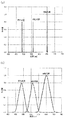
- FIG. 4 shows a graph showing the light intensity distributions of the red light source, the green light source, and the blue light source.
- FIG. 4A is a light intensity distribution when each light source is a laser light source
- FIG. 4B is a light intensity distribution. It is a light intensity distribution when each light source is an LED light source.
- the peak of luminosity is around 550 nm, so that the subject sees green most brightly. It is desirable for the subject to use illumination light with less glare, but if the total amount of light is reduced, there is a problem that a noisy fundus image is taken. Therefore, it is preferable that the amount of red light is larger than the amount of green light and blue light.
- the light amount of the red laser light source 11 is set to 450 ⁇ W
- the light amount of the green laser light source 12 is set to 350 ⁇ W
- the light amount of the blue laser light source 13 is set to 250 ⁇ W.
- the subject can feel less glare, and when the blue light becomes stronger, light damage to the retina is more likely to occur, so the blue color
- the amount of light By making the amount of light smaller than the amount of red light, the occurrence of light damage can be suppressed. As a result, it is possible to take a high-contrast fundus image of the blood vessel image with appropriate brightness without causing the subject to feel glare.
- the present invention is not limited to the above embodiment, and various modifications can be made.
- the central reflection mirror 2 which is an optical path dividing device may be changed to a beam splitter or the like, and the configuration of the first scanning device 3, the second scanning device 5, the light source unit 1, and the light receiving system 7 is not necessarily the present embodiment. It does not have to have the same configuration as.
- the peak wavelength of the red light emitted from the red laser light source 11 is 650 nm
- the peak wavelength of the green light emitted from the green laser light source 12 is 560 nm
- the peak wavelength of the blue light emitted from the blue laser light source 13 is 488 nm.
- the peak wavelength of the near-infrared light emitted from the near-infrared laser light source 14 is set to 780 nm
- the amount of light of the red laser light source 11 is 450 ⁇ W
- the amount of light of the green laser light source 12 is 350 ⁇ W
- the amount of light of the blue laser light source 13 is 350 ⁇ W.
- the fundus Ef was photographed at 250 ⁇ W.
- the photographed fundus image is shown in FIG. 5 (a).
- the difference in color and brightness between the blood vessel image and the retinal tissue is large, and the blood vessel image is very clearly visible. This is due to the clear black and white between the blood vessels and the retinal tissue in the green fundus image.
- the color composite image of FIG. 5B the color and brightness of the blood vessel image and the retinal tissue image are close to each other, and the blood vessel image looks unclear. This is due to the fact that there is little difference in black and white between the blood vessels and the retinal tissue in the green fundus image.
- the peak wavelength of the green light of the green light source used for taking a color fundus image is set based on the ratio of the absorbance of hemoglobin representing the color of blood vessels to the absorbance of melanin representing the color of retinal tissue, that is, 560 nm.
- the difference between the color of the retinal tissue and the color of the blood vessel becomes clear, and it can be seen that a high-contrast fundus image of the blood vessel image can be taken.
Landscapes
- Life Sciences & Earth Sciences (AREA)
- Health & Medical Sciences (AREA)
- Medical Informatics (AREA)
- Biophysics (AREA)
- Ophthalmology & Optometry (AREA)
- Engineering & Computer Science (AREA)
- Biomedical Technology (AREA)
- Heart & Thoracic Surgery (AREA)
- Physics & Mathematics (AREA)
- Molecular Biology (AREA)
- Surgery (AREA)
- Animal Behavior & Ethology (AREA)
- General Health & Medical Sciences (AREA)
- Public Health (AREA)
- Veterinary Medicine (AREA)
- Eye Examination Apparatus (AREA)
Priority Applications (1)
| Application Number | Priority Date | Filing Date | Title |
|---|---|---|---|
| JP2021535400A JPWO2021020466A1 (https=) | 2019-07-30 | 2020-07-29 |
Applications Claiming Priority (2)
| Application Number | Priority Date | Filing Date | Title |
|---|---|---|---|
| JP2019139821 | 2019-07-30 | ||
| JP2019-139821 | 2019-07-30 |
Publications (1)
| Publication Number | Publication Date |
|---|---|
| WO2021020466A1 true WO2021020466A1 (ja) | 2021-02-04 |
Family
ID=74229962
Family Applications (1)
| Application Number | Title | Priority Date | Filing Date |
|---|---|---|---|
| PCT/JP2020/029130 Ceased WO2021020466A1 (ja) | 2019-07-30 | 2020-07-29 | 眼底撮影装置 |
Country Status (2)
| Country | Link |
|---|---|
| JP (1) | JPWO2021020466A1 (https=) |
| WO (1) | WO2021020466A1 (https=) |
Citations (4)
| Publication number | Priority date | Publication date | Assignee | Title |
|---|---|---|---|---|
| JPH02295539A (ja) * | 1989-05-08 | 1990-12-06 | Kowa Co | 眼底血管識別方法及び装置 |
| US20010007494A1 (en) * | 2000-01-07 | 2001-07-12 | Nidek Co., Ltd. | Ophthalmic apparatus |
| JP2001517521A (ja) * | 1997-10-01 | 2001-10-09 | アプライド スペクトラル イメージング リミテッド | 眼のスペクトル生物画像診断 |
| US20100085537A1 (en) * | 2008-10-06 | 2010-04-08 | The Catholic University Of America | Lenslet array for retinal oximetry |
-
2020
- 2020-07-29 JP JP2021535400A patent/JPWO2021020466A1/ja active Pending
- 2020-07-29 WO PCT/JP2020/029130 patent/WO2021020466A1/ja not_active Ceased
Patent Citations (5)
| Publication number | Priority date | Publication date | Assignee | Title |
|---|---|---|---|---|
| JPH02295539A (ja) * | 1989-05-08 | 1990-12-06 | Kowa Co | 眼底血管識別方法及び装置 |
| JP2001517521A (ja) * | 1997-10-01 | 2001-10-09 | アプライド スペクトラル イメージング リミテッド | 眼のスペクトル生物画像診断 |
| US20010007494A1 (en) * | 2000-01-07 | 2001-07-12 | Nidek Co., Ltd. | Ophthalmic apparatus |
| JP2001190499A (ja) * | 2000-01-07 | 2001-07-17 | Nidek Co Ltd | 眼科装置 |
| US20100085537A1 (en) * | 2008-10-06 | 2010-04-08 | The Catholic University Of America | Lenslet array for retinal oximetry |
Also Published As
| Publication number | Publication date |
|---|---|
| JPWO2021020466A1 (https=) | 2021-02-04 |
Similar Documents
| Publication | Publication Date | Title |
|---|---|---|
| JP5209377B2 (ja) | 眼底撮影装置 | |
| US20110001927A1 (en) | Fundus scanning apparatus | |
| JP6734642B2 (ja) | 眼科装置 | |
| JP7302342B2 (ja) | 眼底撮影装置 | |
| JP7226426B2 (ja) | 眼底撮影装置 | |
| JP5179265B2 (ja) | 眼科撮影装置 | |
| JP2016028687A (ja) | 走査型レーザー検眼鏡 | |
| JP2010259675A (ja) | 網膜機能計測装置 | |
| JP7376847B2 (ja) | 眼底画像処理装置および眼底画像処理プログラム | |
| JP5255514B2 (ja) | 眼科撮影装置 | |
| JP4585814B2 (ja) | 眼科装置 | |
| CN112367902A (zh) | 眼摄影装置以及眼摄影系统 | |
| JP2020156705A (ja) | 眼科装置及びその制御方法、並びに、プログラム | |
| JP6884995B2 (ja) | 眼科撮影装置および画像処理プログム | |
| JP7200516B2 (ja) | 眼底撮影装置 | |
| JP7355194B2 (ja) | 眼底撮影装置 | |
| JP7024294B2 (ja) | 眼科撮影装置 | |
| JP2003305009A (ja) | 眼科検査装置 | |
| WO2021020466A1 (ja) | 眼底撮影装置 | |
| JP7098964B2 (ja) | 眼底撮影装置 | |
| JP5508140B2 (ja) | 眼底撮像装置及びその処理方法 | |
| JP7447902B2 (ja) | 眼科撮影装置 | |
| JP6739183B2 (ja) | 眼科装置 | |
| JP4659173B2 (ja) | 眼底カメラ | |
| JP2022117831A (ja) | 眼底撮影装置 |
Legal Events
| Date | Code | Title | Description |
|---|---|---|---|
| 121 | Ep: the epo has been informed by wipo that ep was designated in this application |
Ref document number: 20846830 Country of ref document: EP Kind code of ref document: A1 |
|
| ENP | Entry into the national phase |
Ref document number: 2021535400 Country of ref document: JP Kind code of ref document: A |
|
| NENP | Non-entry into the national phase |
Ref country code: DE |
|
| 122 | Ep: pct application non-entry in european phase |
Ref document number: 20846830 Country of ref document: EP Kind code of ref document: A1 |