WO2021020237A1 - Batterie secondaire, bloc-batterie, dispositif électronique, outil électrique, aéronef électrique et véhicule électrique - Google Patents
Batterie secondaire, bloc-batterie, dispositif électronique, outil électrique, aéronef électrique et véhicule électrique Download PDFInfo
- Publication number
- WO2021020237A1 WO2021020237A1 PCT/JP2020/028295 JP2020028295W WO2021020237A1 WO 2021020237 A1 WO2021020237 A1 WO 2021020237A1 JP 2020028295 W JP2020028295 W JP 2020028295W WO 2021020237 A1 WO2021020237 A1 WO 2021020237A1
- Authority
- WO
- WIPO (PCT)
- Prior art keywords
- active material
- negative electrode
- positive electrode
- secondary battery
- electrode active
- Prior art date
Links
- 238000004804 winding Methods 0.000 claims abstract description 38
- 239000007773 negative electrode material Substances 0.000 claims abstract description 34
- 239000007774 positive electrode material Substances 0.000 claims abstract description 31
- 239000011888 foil Substances 0.000 claims abstract description 30
- 238000005452 bending Methods 0.000 claims abstract description 12
- 239000011149 active material Substances 0.000 claims description 54
- 239000000463 material Substances 0.000 claims description 19
- 238000006243 chemical reaction Methods 0.000 claims description 10
- PXHVJJICTQNCMI-UHFFFAOYSA-N Nickel Chemical compound [Ni] PXHVJJICTQNCMI-UHFFFAOYSA-N 0.000 claims description 8
- RYGMFSIKBFXOCR-UHFFFAOYSA-N Copper Chemical compound [Cu] RYGMFSIKBFXOCR-UHFFFAOYSA-N 0.000 claims description 6
- 230000010365 information processing Effects 0.000 claims description 6
- 229910052782 aluminium Inorganic materials 0.000 claims description 5
- XAGFODPZIPBFFR-UHFFFAOYSA-N aluminium Chemical compound [Al] XAGFODPZIPBFFR-UHFFFAOYSA-N 0.000 claims description 5
- 239000002131 composite material Substances 0.000 claims description 5
- 229910052802 copper Inorganic materials 0.000 claims description 4
- 239000010949 copper Substances 0.000 claims description 4
- 229910052759 nickel Inorganic materials 0.000 claims description 4
- 239000000126 substance Substances 0.000 claims description 4
- 229910000838 Al alloy Inorganic materials 0.000 claims description 3
- 229910000881 Cu alloy Inorganic materials 0.000 claims description 3
- 229910000990 Ni alloy Inorganic materials 0.000 claims description 3
- 238000003466 welding Methods 0.000 description 24
- HBBGRARXTFLTSG-UHFFFAOYSA-N Lithium ion Chemical compound [Li+] HBBGRARXTFLTSG-UHFFFAOYSA-N 0.000 description 22
- 229910001416 lithium ion Inorganic materials 0.000 description 22
- 238000000034 method Methods 0.000 description 16
- -1 polybutylene terephthalate Polymers 0.000 description 15
- WHXSMMKQMYFTQS-UHFFFAOYSA-N Lithium Chemical compound [Li] WHXSMMKQMYFTQS-UHFFFAOYSA-N 0.000 description 14
- 238000001514 detection method Methods 0.000 description 14
- 229910052744 lithium Inorganic materials 0.000 description 14
- 150000001875 compounds Chemical class 0.000 description 13
- 239000008151 electrolyte solution Substances 0.000 description 11
- 238000007599 discharging Methods 0.000 description 10
- 238000010586 diagram Methods 0.000 description 9
- 229920000642 polymer Polymers 0.000 description 9
- 235000002639 sodium chloride Nutrition 0.000 description 9
- 239000003575 carbonaceous material Substances 0.000 description 8
- 150000003839 salts Chemical class 0.000 description 8
- 238000003860 storage Methods 0.000 description 8
- OKTJSMMVPCPJKN-UHFFFAOYSA-N Carbon Chemical compound [C] OKTJSMMVPCPJKN-UHFFFAOYSA-N 0.000 description 7
- 230000000052 comparative effect Effects 0.000 description 6
- 230000000694 effects Effects 0.000 description 6
- 239000003792 electrolyte Substances 0.000 description 6
- 230000007246 mechanism Effects 0.000 description 6
- 229910052751 metal Inorganic materials 0.000 description 6
- 239000006258 conductive agent Substances 0.000 description 5
- 239000002184 metal Substances 0.000 description 5
- 230000008569 process Effects 0.000 description 5
- 239000011810 insulating material Substances 0.000 description 4
- 239000002033 PVDF binder Substances 0.000 description 3
- 229910000147 aluminium phosphate Inorganic materials 0.000 description 3
- 239000003125 aqueous solvent Substances 0.000 description 3
- 239000011248 coating agent Substances 0.000 description 3
- 238000000576 coating method Methods 0.000 description 3
- 239000013078 crystal Substances 0.000 description 3
- 239000011883 electrode binding agent Substances 0.000 description 3
- 229910002804 graphite Inorganic materials 0.000 description 3
- 239000010439 graphite Substances 0.000 description 3
- 229910003002 lithium salt Inorganic materials 0.000 description 3
- 159000000002 lithium salts Chemical class 0.000 description 3
- 238000004519 manufacturing process Methods 0.000 description 3
- 239000007769 metal material Substances 0.000 description 3
- 230000004048 modification Effects 0.000 description 3
- 238000012986 modification Methods 0.000 description 3
- NBIIXXVUZAFLBC-UHFFFAOYSA-N phosphoric acid Substances OP(O)(O)=O NBIIXXVUZAFLBC-UHFFFAOYSA-N 0.000 description 3
- 229920001707 polybutylene terephthalate Polymers 0.000 description 3
- 229920002981 polyvinylidene fluoride Polymers 0.000 description 3
- 239000002904 solvent Substances 0.000 description 3
- 230000037303 wrinkles Effects 0.000 description 3
- XEEYBQQBJWHFJM-UHFFFAOYSA-N Iron Chemical compound [Fe] XEEYBQQBJWHFJM-UHFFFAOYSA-N 0.000 description 2
- 239000000571 coke Substances 0.000 description 2
- 239000000470 constituent Substances 0.000 description 2
- 239000011889 copper foil Substances 0.000 description 2
- 238000000354 decomposition reaction Methods 0.000 description 2
- 239000010419 fine particle Substances 0.000 description 2
- 230000006870 function Effects 0.000 description 2
- 229910021469 graphitizable carbon Inorganic materials 0.000 description 2
- 239000010954 inorganic particle Substances 0.000 description 2
- 238000009413 insulation Methods 0.000 description 2
- 238000005304 joining Methods 0.000 description 2
- MHCFAGZWMAWTNR-UHFFFAOYSA-M lithium perchlorate Chemical compound [Li+].[O-]Cl(=O)(=O)=O MHCFAGZWMAWTNR-UHFFFAOYSA-M 0.000 description 2
- 229910001496 lithium tetrafluoroborate Inorganic materials 0.000 description 2
- 239000012528 membrane Substances 0.000 description 2
- 229920000620 organic polymer Polymers 0.000 description 2
- 239000003960 organic solvent Substances 0.000 description 2
- 230000002093 peripheral effect Effects 0.000 description 2
- BBEAQIROQSPTKN-UHFFFAOYSA-N pyrene Chemical compound C1=CC=C2C=CC3=CC=CC4=CC=C1C2=C43 BBEAQIROQSPTKN-UHFFFAOYSA-N 0.000 description 2
- 238000007789 sealing Methods 0.000 description 2
- 239000000243 solution Substances 0.000 description 2
- 229920003051 synthetic elastomer Polymers 0.000 description 2
- 239000000057 synthetic resin Substances 0.000 description 2
- 229920003002 synthetic resin Polymers 0.000 description 2
- 239000005061 synthetic rubber Substances 0.000 description 2
- YCKRFDGAMUMZLT-UHFFFAOYSA-N Fluorine atom Chemical compound [F] YCKRFDGAMUMZLT-UHFFFAOYSA-N 0.000 description 1
- 229910010238 LiAlCl 4 Inorganic materials 0.000 description 1
- 229910015015 LiAsF 6 Inorganic materials 0.000 description 1
- 229910013063 LiBF 4 Inorganic materials 0.000 description 1
- 229910013870 LiPF 6 Inorganic materials 0.000 description 1
- BPQQTUXANYXVAA-UHFFFAOYSA-N Orthosilicate Chemical compound [O-][Si]([O-])([O-])[O-] BPQQTUXANYXVAA-UHFFFAOYSA-N 0.000 description 1
- 239000004698 Polyethylene Substances 0.000 description 1
- 239000004642 Polyimide Substances 0.000 description 1
- 239000004743 Polypropylene Substances 0.000 description 1
- 208000037062 Polyps Diseases 0.000 description 1
- FAPWRFPIFSIZLT-UHFFFAOYSA-M Sodium chloride Chemical compound [Na+].[Cl-] FAPWRFPIFSIZLT-UHFFFAOYSA-M 0.000 description 1
- JJVGROTXXZVGGN-UHFFFAOYSA-H [Li+].[Li+].[Li+].[Li+].[Li+].[Li+].[F-].[F-].[F-].[F-].[F-].[F-] Chemical compound [Li+].[Li+].[Li+].[Li+].[Li+].[Li+].[F-].[F-].[F-].[F-].[F-].[F-] JJVGROTXXZVGGN-UHFFFAOYSA-H 0.000 description 1
- 230000002159 abnormal effect Effects 0.000 description 1
- 230000001133 acceleration Effects 0.000 description 1
- 239000006230 acetylene black Substances 0.000 description 1
- 239000000654 additive Substances 0.000 description 1
- 229910045601 alloy Inorganic materials 0.000 description 1
- 239000000956 alloy Substances 0.000 description 1
- 229910003481 amorphous carbon Inorganic materials 0.000 description 1
- 239000010426 asphalt Substances 0.000 description 1
- 238000001354 calcination Methods 0.000 description 1
- 229910052799 carbon Inorganic materials 0.000 description 1
- 239000006229 carbon black Substances 0.000 description 1
- 235000019241 carbon black Nutrition 0.000 description 1
- 238000010000 carbonizing Methods 0.000 description 1
- 150000001733 carboxylic acid esters Chemical class 0.000 description 1
- 239000000919 ceramic Substances 0.000 description 1
- 150000005678 chain carbonates Chemical class 0.000 description 1
- 230000008859 change Effects 0.000 description 1
- 239000012141 concentrate Substances 0.000 description 1
- 229920001940 conductive polymer Polymers 0.000 description 1
- 239000004020 conductor Substances 0.000 description 1
- PMHQVHHXPFUNSP-UHFFFAOYSA-M copper(1+);methylsulfanylmethane;bromide Chemical compound Br[Cu].CSC PMHQVHHXPFUNSP-UHFFFAOYSA-M 0.000 description 1
- 150000005676 cyclic carbonates Chemical class 0.000 description 1
- 230000007547 defect Effects 0.000 description 1
- SMBQBQBNOXIFSF-UHFFFAOYSA-N dilithium Chemical compound [Li][Li] SMBQBQBNOXIFSF-UHFFFAOYSA-N 0.000 description 1
- 238000001035 drying Methods 0.000 description 1
- 229920001971 elastomer Polymers 0.000 description 1
- 238000000605 extraction Methods 0.000 description 1
- GVEPBJHOBDJJJI-UHFFFAOYSA-N fluoranthrene Natural products C1=CC(C2=CC=CC=C22)=C3C2=CC=CC3=C1 GVEPBJHOBDJJJI-UHFFFAOYSA-N 0.000 description 1
- 239000011737 fluorine Substances 0.000 description 1
- 229910052731 fluorine Inorganic materials 0.000 description 1
- 239000007849 furan resin Substances 0.000 description 1
- 239000011809 glassy carbon fiber Substances 0.000 description 1
- 230000020169 heat generation Effects 0.000 description 1
- 150000002500 ions Chemical class 0.000 description 1
- 229910052742 iron Inorganic materials 0.000 description 1
- 239000003273 ketjen black Substances 0.000 description 1
- 150000002596 lactones Chemical class 0.000 description 1
- AMXOYNBUYSYVKV-UHFFFAOYSA-M lithium bromide Chemical compound [Li+].[Br-] AMXOYNBUYSYVKV-UHFFFAOYSA-M 0.000 description 1
- KWGKDLIKAYFUFQ-UHFFFAOYSA-M lithium chloride Chemical compound [Li+].[Cl-] KWGKDLIKAYFUFQ-UHFFFAOYSA-M 0.000 description 1
- 229910001486 lithium perchlorate Inorganic materials 0.000 description 1
- 229910001537 lithium tetrachloroaluminate Inorganic materials 0.000 description 1
- OWNSEPXOQWKTKG-UHFFFAOYSA-M lithium;methanesulfonate Chemical compound [Li+].CS([O-])(=O)=O OWNSEPXOQWKTKG-UHFFFAOYSA-M 0.000 description 1
- MCVFFRWZNYZUIJ-UHFFFAOYSA-M lithium;trifluoromethanesulfonate Chemical compound [Li+].[O-]S(=O)(=O)C(F)(F)F MCVFFRWZNYZUIJ-UHFFFAOYSA-M 0.000 description 1
- 238000005259 measurement Methods 0.000 description 1
- MPDOUGUGIVBSGZ-UHFFFAOYSA-N n-(cyclobutylmethyl)-3-(trifluoromethyl)aniline Chemical compound FC(F)(F)C1=CC=CC(NCC2CCC2)=C1 MPDOUGUGIVBSGZ-UHFFFAOYSA-N 0.000 description 1
- 239000011331 needle coke Substances 0.000 description 1
- 150000002825 nitriles Chemical class 0.000 description 1
- 229910021470 non-graphitizable carbon Inorganic materials 0.000 description 1
- 239000010450 olivine Substances 0.000 description 1
- 229910052609 olivine Inorganic materials 0.000 description 1
- TWNQGVIAIRXVLR-UHFFFAOYSA-N oxo(oxoalumanyloxy)alumane Chemical compound O=[Al]O[Al]=O TWNQGVIAIRXVLR-UHFFFAOYSA-N 0.000 description 1
- 230000003071 parasitic effect Effects 0.000 description 1
- 239000002245 particle Substances 0.000 description 1
- 239000002006 petroleum coke Substances 0.000 description 1
- 239000005011 phenolic resin Substances 0.000 description 1
- 239000006253 pitch coke Substances 0.000 description 1
- 229920000573 polyethylene Polymers 0.000 description 1
- 229920001721 polyimide Polymers 0.000 description 1
- 239000002861 polymer material Substances 0.000 description 1
- 229920001155 polypropylene Polymers 0.000 description 1
- 229920001343 polytetrafluoroethylene Polymers 0.000 description 1
- 239000004810 polytetrafluoroethylene Substances 0.000 description 1
- 238000010248 power generation Methods 0.000 description 1
- 238000003825 pressing Methods 0.000 description 1
- 239000002296 pyrolytic carbon Substances 0.000 description 1
- 230000001172 regenerating effect Effects 0.000 description 1
- 230000003014 reinforcing effect Effects 0.000 description 1
- 238000007788 roughening Methods 0.000 description 1
- 239000005060 rubber Substances 0.000 description 1
- 238000010079 rubber tapping Methods 0.000 description 1
- 239000004065 semiconductor Substances 0.000 description 1
- 239000011780 sodium chloride Substances 0.000 description 1
- 229910052596 spinel Inorganic materials 0.000 description 1
- 239000011029 spinel Substances 0.000 description 1
- 229920003048 styrene butadiene rubber Polymers 0.000 description 1
- 230000008961 swelling Effects 0.000 description 1
- 229920001059 synthetic polymer Polymers 0.000 description 1
- RIUWBIIVUYSTCN-UHFFFAOYSA-N trilithium borate Chemical compound [Li+].[Li+].[Li+].[O-]B([O-])[O-] RIUWBIIVUYSTCN-UHFFFAOYSA-N 0.000 description 1
- 238000005406 washing Methods 0.000 description 1
- XLYOFNOQVPJJNP-UHFFFAOYSA-N water Substances O XLYOFNOQVPJJNP-UHFFFAOYSA-N 0.000 description 1
- 239000002023 wood Substances 0.000 description 1
Images


Classifications
-
- H—ELECTRICITY
- H01—ELECTRIC ELEMENTS
- H01M—PROCESSES OR MEANS, e.g. BATTERIES, FOR THE DIRECT CONVERSION OF CHEMICAL ENERGY INTO ELECTRICAL ENERGY
- H01M4/00—Electrodes
- H01M4/02—Electrodes composed of, or comprising, active material
- H01M4/64—Carriers or collectors
- H01M4/66—Selection of materials
- H01M4/661—Metal or alloys, e.g. alloy coatings
-
- H—ELECTRICITY
- H01—ELECTRIC ELEMENTS
- H01M—PROCESSES OR MEANS, e.g. BATTERIES, FOR THE DIRECT CONVERSION OF CHEMICAL ENERGY INTO ELECTRICAL ENERGY
- H01M50/00—Constructional details or processes of manufacture of the non-active parts of electrochemical cells other than fuel cells, e.g. hybrid cells
- H01M50/20—Mountings; Secondary casings or frames; Racks, modules or packs; Suspension devices; Shock absorbers; Transport or carrying devices; Holders
- H01M50/249—Mountings; Secondary casings or frames; Racks, modules or packs; Suspension devices; Shock absorbers; Transport or carrying devices; Holders specially adapted for aircraft or vehicles, e.g. cars or trains
-
- B—PERFORMING OPERATIONS; TRANSPORTING
- B64—AIRCRAFT; AVIATION; COSMONAUTICS
- B64D—EQUIPMENT FOR FITTING IN OR TO AIRCRAFT; FLIGHT SUITS; PARACHUTES; ARRANGEMENT OR MOUNTING OF POWER PLANTS OR PROPULSION TRANSMISSIONS IN AIRCRAFT
- B64D27/00—Arrangement or mounting of power plants in aircraft; Aircraft characterised by the type or position of power plants
- B64D27/02—Aircraft characterised by the type or position of power plants
- B64D27/24—Aircraft characterised by the type or position of power plants using steam or spring force
-
- B—PERFORMING OPERATIONS; TRANSPORTING
- B64—AIRCRAFT; AVIATION; COSMONAUTICS
- B64U—UNMANNED AERIAL VEHICLES [UAV]; EQUIPMENT THEREFOR
- B64U50/00—Propulsion; Power supply
- B64U50/30—Supply or distribution of electrical power
-
- H—ELECTRICITY
- H01—ELECTRIC ELEMENTS
- H01M—PROCESSES OR MEANS, e.g. BATTERIES, FOR THE DIRECT CONVERSION OF CHEMICAL ENERGY INTO ELECTRICAL ENERGY
- H01M10/00—Secondary cells; Manufacture thereof
- H01M10/05—Accumulators with non-aqueous electrolyte
- H01M10/058—Construction or manufacture
- H01M10/0587—Construction or manufacture of accumulators having only wound construction elements, i.e. wound positive electrodes, wound negative electrodes and wound separators
-
- H—ELECTRICITY
- H01—ELECTRIC ELEMENTS
- H01M—PROCESSES OR MEANS, e.g. BATTERIES, FOR THE DIRECT CONVERSION OF CHEMICAL ENERGY INTO ELECTRICAL ENERGY
- H01M50/00—Constructional details or processes of manufacture of the non-active parts of electrochemical cells other than fuel cells, e.g. hybrid cells
- H01M50/50—Current conducting connections for cells or batteries
- H01M50/531—Electrode connections inside a battery casing
-
- B—PERFORMING OPERATIONS; TRANSPORTING
- B64—AIRCRAFT; AVIATION; COSMONAUTICS
- B64U—UNMANNED AERIAL VEHICLES [UAV]; EQUIPMENT THEREFOR
- B64U50/00—Propulsion; Power supply
- B64U50/10—Propulsion
- B64U50/19—Propulsion using electrically powered motors
-
- H—ELECTRICITY
- H01—ELECTRIC ELEMENTS
- H01M—PROCESSES OR MEANS, e.g. BATTERIES, FOR THE DIRECT CONVERSION OF CHEMICAL ENERGY INTO ELECTRICAL ENERGY
- H01M2220/00—Batteries for particular applications
- H01M2220/20—Batteries in motive systems, e.g. vehicle, ship, plane
-
- H—ELECTRICITY
- H01—ELECTRIC ELEMENTS
- H01M—PROCESSES OR MEANS, e.g. BATTERIES, FOR THE DIRECT CONVERSION OF CHEMICAL ENERGY INTO ELECTRICAL ENERGY
- H01M2220/00—Batteries for particular applications
- H01M2220/30—Batteries in portable systems, e.g. mobile phone, laptop
-
- Y—GENERAL TAGGING OF NEW TECHNOLOGICAL DEVELOPMENTS; GENERAL TAGGING OF CROSS-SECTIONAL TECHNOLOGIES SPANNING OVER SEVERAL SECTIONS OF THE IPC; TECHNICAL SUBJECTS COVERED BY FORMER USPC CROSS-REFERENCE ART COLLECTIONS [XRACs] AND DIGESTS
- Y02—TECHNOLOGIES OR APPLICATIONS FOR MITIGATION OR ADAPTATION AGAINST CLIMATE CHANGE
- Y02E—REDUCTION OF GREENHOUSE GAS [GHG] EMISSIONS, RELATED TO ENERGY GENERATION, TRANSMISSION OR DISTRIBUTION
- Y02E60/00—Enabling technologies; Technologies with a potential or indirect contribution to GHG emissions mitigation
- Y02E60/10—Energy storage using batteries
-
- Y—GENERAL TAGGING OF NEW TECHNOLOGICAL DEVELOPMENTS; GENERAL TAGGING OF CROSS-SECTIONAL TECHNOLOGIES SPANNING OVER SEVERAL SECTIONS OF THE IPC; TECHNICAL SUBJECTS COVERED BY FORMER USPC CROSS-REFERENCE ART COLLECTIONS [XRACs] AND DIGESTS
- Y02—TECHNOLOGIES OR APPLICATIONS FOR MITIGATION OR ADAPTATION AGAINST CLIMATE CHANGE
- Y02P—CLIMATE CHANGE MITIGATION TECHNOLOGIES IN THE PRODUCTION OR PROCESSING OF GOODS
- Y02P70/00—Climate change mitigation technologies in the production process for final industrial or consumer products
- Y02P70/50—Manufacturing or production processes characterised by the final manufactured product
Definitions
- the present invention relates to a secondary battery, a battery pack, an electronic device, an electric tool, an electric aircraft, and an electric vehicle.
- Lithium-ion batteries are being developed for applications that require high output, such as power tools and automobiles.
- One method of achieving high output is high-rate discharge in which a relatively large current is passed from the battery. In high-rate discharge, a large current flows, so the internal resistance of the battery becomes a problem.
- Patent Document 1 describes a core in which an active material is not coated on the end faces of a spiral electrode body in which an active material is coated on a strip-shaped electrode core body and a negative electrode plate is wound via a separator. It is equipped with an exposed body part, and before forming a flat surface at the end in the tapping process, eight radial bending auxiliary grooves are provided in the protruding part of the exposed part of the core body so that the flat surface is formed in the portion without the groove.
- the battery structure and the manufacturing method are disclosed in which the battery is formed to ensure welding with the current collector plate.
- one of the objects of the present invention is to provide a battery for high-rate discharge that can be reliably welded.
- the present invention includes the above-mentioned secondary battery and A control unit that controls the secondary battery and It is a battery pack having an exterior body containing a secondary battery.
- the present invention is an electronic device having the above-mentioned secondary battery or the above-mentioned battery pack.
- the present invention is a power tool having the above-mentioned battery pack and using the battery pack as a power source.
- the present invention includes the above-mentioned battery pack and With multiple rotors, A motor that rotates each rotor and Support shafts that support the rotor and motor, respectively, A motor control unit that controls the rotation of the motor, Equipped with a power supply line that supplies power to the motor An electric aircraft with a battery pack connected to a power supply line.
- the present invention has the secondary battery described above.
- a converter that receives power from a secondary battery and converts it into vehicle driving force, It is an electric vehicle having a control device that performs information processing on vehicle control based on information on a secondary battery.
- the foil and the current collector plate can be reliably welded, the internal resistance of the battery can be reduced, or a high output battery can be realized. It should be noted that the contents of the present invention are not limitedly interpreted by the effects exemplified in the present specification.
- FIG. 1 is a cross-sectional view of a battery according to an embodiment.
- FIG. 2 is a diagram illustrating an example of the arrangement relationship between the positive electrode, the negative electrode, and the separator in the electrode winding body.
- FIG. 3A is a plan view of the positive electrode current collector plate
- FIG. 3B is a plan view of the negative electrode current collector plate.
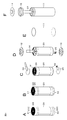
- 4A to 4F are diagrams illustrating a battery assembly process according to the embodiment.
- FIG. 5 is a front view and a bottom view of the jig used in the embodiment of the embodiment.
- FIG. 6 is a front view of another jig used in the embodiment of one embodiment.
- FIG. 7A is a diagram showing an end face of the embodiment, and FIG.
- a cylindrical lithium ion battery will be described as an example of the secondary battery.
- a battery other than the lithium ion battery or a battery other than the cylindrical shape may be used.
- FIG. 1 is a schematic cross-sectional view of the lithium ion battery 1.
- the lithium ion battery 1 is, for example, a cylindrical lithium ion battery 1 in which an electrode winding body 20 is housed inside an outer can 11.
- the lithium ion battery 1 includes, for example, a pair of insulating plates 12 and 13 and an electrode winding body 20 inside a cylindrical outer can 11.
- the lithium ion battery 1 may further include, for example, any one or more of the thermal resistance (PTC) element and the reinforcing member inside the outer can 11.
- PTC thermal resistance
- the outer can 11 is mainly a member for accommodating the electrode winding body 20.
- the outer can 11 is, for example, a cylindrical container in which one end is open and the other end is closed. That is, the outer can 11 has an open end portion (open end portion 11N).
- the outer can 11 contains any one or more of metal materials such as iron, aluminum and alloys thereof. However, the surface of the outer can 11 may be plated with any one or more of metal materials such as nickel.
- Each of the insulating plates 12 and 13 is, for example, a dish-shaped plate having a surface perpendicular to the winding axis of the electrode winding body 20, that is, a surface perpendicular to the Z axis in FIG. Further, the insulating plates 12 and 13 are arranged so as to sandwich the electrode winding body 20 with each other, for example.
- the battery lid 14 and the safety valve mechanism 30 are crimped to the open end portion 11N of the outer can 11 via the gasket 15.
- the battery lid 14 is the "lid member” of the embodiment of the present invention
- the gasket 15 is the “sealing member” of the embodiment of the present invention.
- the outer can 11 is sealed in a state where the electrode winding body 20 and the like are housed inside the outer can 11. Therefore, a structure (caulking structure 11R) in which the battery lid 14 and the safety valve mechanism 30 are crimped via the gasket 15 is formed at the open end portion 11N of the outer can 11. That is, the bent portion 11P is a so-called crimp portion, and the caulking structure 11R is a so-called crimp structure.
- the battery lid 14 is a member that mainly closes the open end 11N of the outer can 11 when the electrode winding body 20 or the like is housed inside the outer can 11.
- the battery lid 14 contains, for example, the same material as the material for forming the outer can 11.
- the central region of the battery lid 14 projects, for example, in the + Z direction. As a result, the region (peripheral region) of the battery lid 14 other than the central region is in contact with, for example, the safety valve mechanism 30.
- the gasket 15 contains, for example, any one or more of the insulating materials.
- the type of the insulating material is not particularly limited, and is, for example, a polymer material such as polybutylene terephthalate (PBT) and polyp-mouth pyrene (PP). Above all, the insulating material is preferably polybutylene terephthalate. This is because the gap between the bent portion 11P and the battery lid 14 is sufficiently sealed while the outer can 11 and the battery lid 14 are electrically separated from each other.
- the safety valve mechanism 30 mainly releases the internal pressure of the outer can 11 by releasing the sealed state of the outer can 11 as necessary when the internal pressure (internal pressure) of the outer can 11 rises.
- the cause of the increase in the internal pressure of the outer can 11 is, for example, a gas generated due to a decomposition reaction of the electrolytic solution during charging / discharging.
- the negative electrode 22 has a negative electrode active material layer 22B formed on one side or both sides of the negative electrode foil 22A, and the material of the negative electrode foil 22A is, for example, a metal foil made of nickel, a nickel alloy, copper, or a copper alloy.
- the separator 23 is a porous and insulating film that electrically insulates the positive electrode 21 and the negative electrode 22 while allowing the movement of substances such as ions and electrolytes.
- the positive electrode active material layer 21B and the negative electrode active material layer 22B each cover many parts of the positive electrode foil 21A and the negative electrode foil 22A, respectively, but both intentionally cover the periphery of one end in the minor axis direction of the band. Absent.
- the portion where the active material layers 21B and 22B are not coated is hereinafter appropriately referred to as an active material uncoated portion.
- the electrode winding body 20 is wound by stacking the positive electrode uncoated portion 21C and the negative electrode active material uncoated portion 22C via a separator 23 so as to face in opposite directions. ..
- the positive electrode active material uncoated portion 21C is made of, for example, aluminum and the negative electrode active material uncoated portion 22C is made of, for example, copper
- the positive electrode active material uncoated portion 21C is generally more negative electrode active material non-coated portion 21C. Softer than the covering portion 22C (low Young rate). Therefore, in one embodiment, A> B and C> D are more preferable.
- the positive electrode active material uncoated portion 21C and the negative electrode active material uncoated portion 22C are bent at the same pressure from both electrode sides at the same time. At that time, the height measured from the tip of the separator 23 of the bent portion may be about the same for the positive electrode 21 and the negative electrode 22.
- the through hole 26 is a hole for inserting the winding core for assembling the electrode winding body 20 and the electrode rod for welding. Since the electrode winding body 20 is wound so that the active material uncoated portion 21C of the positive electrode and the active material uncoated portion 22C of the negative electrode face each other in opposite directions, one end (end) of the electrode winding body is wound. The positive electrode active material uncoated portion 21C gathers in the portion 41), and the negative electrode active material uncoated portion 22C gathers in the other end (end 42) of the electrode winding body 20.
- the active material uncoated portions 21C and 22C are bent, and the end portions 41 and 42 form a surface.
- the bending direction is from the outer edges 27 and 28 of the ends 41 and 42 toward the through hole 26, and the active material uncoated portions on the adjacent circumferences are overlapped and bent in a wound state.
- this surface may be a flat surface or a surface having a raised portion. In any case, the surface may be smooth enough not to affect the bonding with the current collector plate even if there are some irregularities.
- a flat surface will be described as an example.
- a groove 43 (see, for example, FIG. 4B) is formed in the radial direction from the through hole 26. The groove 43 extends from the outer edges 27, 28 of the ends 41, 42 to the through hole 26 having the central axis.
- the groove 43 remains in the flat surface even after the active material uncoated portions 21C and 22C are bent, and the portion without the groove 43 is joined (welded or the like) to the positive electrode current collector plate 24 or the negative electrode current collector plate 25. ing. In addition to the flat surface, the groove 43 may be joined to a part of the current collector plates 24 and 25.
- the detailed configuration of the electrode winding body 20, that is, the detailed configurations of the positive electrode 21, the negative electrode 22, the separator 23, and the electrolytic solution will be described later.
- FIGS. 3A and 3B show an example of a current collector plate.
- FIG. 3A is a positive electrode current collector plate 24, and FIG. 3B is a negative electrode current collector plate 25.
- the material of the positive current collector plate 24 is, for example, a metal plate made of aluminum or an aluminum alloy alone or a composite material
- the material of the negative electrode current collector plate 25 is, for example, a nickel, a nickel alloy, a copper or a copper alloy single unit or a composite material. It is a metal plate made of wood.
- the shape of the positive electrode current collector plate 24 is a flat fan-shaped fan-shaped portion 31 with a rectangular strip-shaped portion 32 attached. There is a hole 35 near the center of the fan-shaped portion 31, and the position of the hole 35 is a position corresponding to the through hole 26.
- the negative electrode current collector plate 25 has a hole 36 near the center of the fan-shaped portion 33, and the position of the hole 36 is a position corresponding to the through hole 26. Since the fan-shaped portion 31 of the positive electrode current collector plate 24 and the fan-shaped portion 33 of the negative electrode current collector plate 25 have a fan shape, they cover a part of the ends 41 and 42. The reason why it does not cover the whole is to allow the electrolytic solution to smoothly penetrate into the electrode winding body when assembling the battery, or to release the gas generated when the battery becomes abnormally high temperature or overcharged to the outside of the battery. This is to make it easier.
- the positive electrode active material layer 21B contains, as the positive electrode active material, any one or more of the positive electrode materials capable of occluding and releasing lithium. However, the positive electrode active material layer 21B may further contain any one or more of other materials such as a positive electrode binder and a positive electrode conductive agent.
- the positive electrode material is preferably a lithium-containing compound, and more specifically, a lithium-containing composite oxide, a lithium-containing phosphoric acid compound, or the like.
- the organic polymer compound calcined product is obtained by calcining (carbonizing) a polymer compound such as a phenol resin and a furan resin at an appropriate temperature.
- the carbon material may be low crystalline carbon heat-treated at a temperature of about 1000 ° C. or lower, or amorphous carbon.
- the shape of the carbon material may be any of fibrous, spherical, granular and scaly.
- the separator 23 may include, for example, the above-mentioned porous film (base material layer) and a polymer compound layer provided on one side or both sides of the base material layer. This is because the adhesion of the separator 23 to each of the positive electrode 21 and the negative electrode 22 is improved, so that the distortion of the electrode winding body 20 is suppressed. As a result, the decomposition reaction of the electrolytic solution is suppressed, and the leakage of the electrolytic solution impregnated in the base material layer is also suppressed. Therefore, the resistance is less likely to increase even if charging and discharging are repeated, and battery swelling is suppressed. Will be done.
- the polymer compound layer contains a polymer compound such as polyvinylidene fluoride. This is because it has excellent physical strength and is electrochemically stable. However, the polymer compound may be other than polyvinylidene fluoride.
- a solution in which the polymer compound is dissolved in an organic solvent or the like is applied to the base material layer, and then the base material layer is dried. After immersing the base material layer in the solution, the base material layer may be dried.
- the polymer compound layer may contain any one or more of insulating particles such as inorganic particles.
- the types of inorganic particles are, for example, aluminum oxide and aluminum nitride.
- the electrolyte contains a solvent and an electrolyte salt. However, the electrolytic solution may further contain any one or more of other materials such as additives.
- the solvent contains any one or more of non-aqueous solvents such as organic solvents.
- the electrolytic solution containing a non-aqueous solvent is a so-called non-aqueous electrolytic solution.
- Non-aqueous solvents are, for example, cyclic carbonates, chain carbonates, lactones, chain carboxylic acid esters and nitriles (mononitriles).
- the electrolyte salt contains, for example, any one or more of salts such as lithium salt.
- the electrolyte salt may contain, for example, a salt other than the lithium salt.
- the salt other than lithium is, for example, a salt of a light metal other than lithium.
- Lithium salts include, for example, lithium hexafluorophosphate (LiPF 6 ), lithium tetrafluoroborate (LiBF 4 ), lithium perchlorate (LiClO 4 ), lithium hexafluorophosphate (LiAsF 6 ), and tetraphenyl.
- Lithium borate LiB (C 6 H 5 ) 4
- lithium methanesulfonate LiCH 3 SO 3
- lithium trifluoromethanesulfonate LiCF 3 SO 3
- lithium tetrachloroaluminate LiAlCl 4
- LiCl lithium chloride
- LiBr lithium bromide
- any one or more of lithium hexafluorophosphate, lithium tetrafluoroborate, lithium perchlorate and lithium hexafluoride is preferable, and lithium hexafluorophosphate is more preferable. ..
- the content of the electrolyte salt is not particularly limited, but is preferably 0.3 mol / kg to 3 mol / kg with respect to the solvent.
- the positive electrode active material is applied to the surface of the strip-shaped positive electrode foil 21A, which is used as the coating portion of the positive electrode 21, and the negative electrode active material is applied to the surface of the band-shaped negative electrode foil 22A, which is applied to the negative electrode 22. It was used as a covering part.
- the active material uncoated portions 21C and 22C in which the positive electrode active material and the negative electrode active material were not coated were produced on one end in the lateral direction of the positive electrode 21 and one end in the lateral direction of the negative electrode 22.
- FIG. 4B by pressing the end of a thin flat plate (for example, 0.5 mm in thickness) perpendicular to the ends 41 and 42, the ends 41 and 42 are locally bent and the groove 43 is formed.
- a groove 43 extending from the through hole 26 in the radial direction toward the central axis was produced.
- the number and arrangement of the grooves 43 shown in FIG. 4B are merely examples.
- FIG. 4C the same pressure is simultaneously applied from both poles in a direction substantially perpendicular to the ends 41 and 42, and the positive electrode active material uncoated portion 21C and the negative electrode active material uncoated portion 22C are bent.
- the ends 41 and 42 were formed so as to be a flat surface.
- the strips 32 and 34 of the current collector plates 24 and 25 are bent, and the insulating plates 12 and 13 (or insulating tape) are attached to the positive electrode current collector plate 24 and the negative electrode current collector plate 25.
- the electrode winding body 20 assembled as described above was inserted into the outer can 11 shown in 4E, and the bottom of the outer can 11 was welded. After the electrolytic solution was injected into the outer can 11, it was sealed with the gasket 15 and the battery lid 14 as shown in FIG. 4F.
- the present invention will be specifically described based on an example in which the lithium ion battery 1 produced as described above is used and the difference in the structure of the active material uncoated portion is compared.
- the present invention is not limited to the examples described below.
- the battery size was 18650 and the number of grooves 43 was 4, 6, or 8.
- the thickness of the active material uncoated portions 21C and 22C was set to 10 ⁇ m.
- the jig 51 shown in FIG. 5 was used to form the groove 43.
- a flat surface portion 52 is provided at the bottom of the jig 51 in FIG. 5, and pins 53 are erected at the center position of the flat surface portion 52 in a direction perpendicular to the flat surface portion 52, and are radially and equiangularly spaced from the pins 53. Therefore, the flat plate portion 54 is erected in the direction perpendicular to the flat surface portion 52.
- the pin 53 was inserted into the through hole 26 of the electrode winding body 20, and the flat plate portion 54 was pressed against the ends 41 and 42 to form the groove 43. Subsequently, the jig 61 shown in FIG. 6 was used to bend the ends 41 and 42.
- the bottom of the jig 61 of FIG. 6 has a flat surface portion 62, and a pin 63 is erected in the center of the flat surface portion 62 in a direction perpendicular to the flat surface portion 62.
- the pin 63 was inserted into the through hole 26 of the electrode winding body 20, and the flat surface portion 62 was pressed against the end portions 41 and 42 to prepare a flat surface.
- the groove 43 was prepared by a jig having no pin 53 and the pin 63, and the ends 41 and 42 were bent to prepare a flat surface.
- FIGS. 8A and 8B show a schematic view of the ends 41 and 42 of the comparative example.
- the through hole 26 was not blocked, whereas the comparison was made.
- the through hole 26 is closed by the bent active material uncoated portions 21C and 22C.
- a welding rod was inserted in the welding process of the bottom of the outer can (FIG. 4D) and welding was possible, but in the comparative example, the welding rod was not inserted and welding was not possible.
- the active material uncoated portions 21C and 22C in the vicinity of the through hole 26 of the end portions 41 and 42 is multiplely bent and densely packed in a region of about 0.7 mm in the depth direction from the surface, and does not protrude into the through hole 26. Therefore, as a result of performing laser welding after stacking the current collector plates 24 and 25, laser welding was possible even in the vicinity of the through hole 26 (there was no welding defect due to perforation or the like).
- the active material uncoated portions 21C and 22C are not bent multiple times and are not densely packed in the vicinity of the through hole 26, and as a result of laser welding, holes and the like are formed. Welding failure occurred.
- the multiplely bent region is 0.1 mm or more and 1.5 mm or less from the surface formed by bending toward the central axis of the structure in which the active material uncoated portions 21C and 22C are wound and overlapping. It is preferably present in the region of the depth of.
- a wall is formed so as not to fall into the through hole 26, so that the active material non-active material that has fallen from the outside near the through hole 26 is formed. It is possible to create a structure in which the covering portions 21C and 22C are densely packed and become denser than the outer peripheral portion. At this time, since the ends 41 and 42 form a flat surface, not only is laser welding sufficiently possible, but also at a location where the welding point density near the through hole 26 is high and a thermal effect occurs during laser welding. However, it can be welded without creating holes.
- the number of grooves 43 was set to 4, 6, or 8, but other numbers may be used.
- the battery size was 18650, but it may be 21700 or a size other than these.
- the positive electrode current collector plate 24 and the negative electrode current collector plate 25 are provided with fan-shaped portions 31 and 33, but may have other shapes.
- FIG. 9 is a block diagram showing a circuit configuration example when a battery according to an embodiment of the present invention (hereinafter, appropriately referred to as a secondary battery) is applied to the battery pack 330.
- the battery pack 300 includes a switch unit 304 including an assembled battery 301, an exterior, a charge control switch 302a, and a discharge control switch 303a, a current detection resistor 307, a temperature detection element 308, and a control unit 310.
- the battery pack 300 includes a positive electrode terminal 321 and a negative electrode terminal 322, and at the time of charging, the positive electrode terminal 321 and the negative electrode terminal 322 are connected to the positive electrode terminal and the negative electrode terminal of the charger, respectively, and charging is performed. Further, when using an electronic device, the positive electrode terminal 321 and the negative electrode terminal 322 are connected to the positive electrode terminal and the negative electrode terminal of the electronic device, respectively, and discharge is performed.
- the assembled battery 301 is formed by connecting a plurality of secondary batteries 301a in series and / or in parallel.
- the secondary battery 301a is the secondary battery of the present invention.
- FIG. 9 shows an example in which six secondary batteries 301a are connected in two parallels and three series (2P3S), but in addition, u parallel v series (u and v are integers). In addition, any connection method may be used.
- the discharge control switch 303a is turned off when the battery voltage becomes the over-discharge detection voltage, and is controlled by the control unit 310 so that the discharge current does not flow in the current path of the assembled battery 301. After the discharge control switch 303a is turned off, only charging is possible via the diode 303b. Further, it is controlled by the control unit 310 so as to be turned off when a large current flows during discharging and to cut off the discharging current flowing in the current path of the assembled battery 301.
- the temperature detection element 308 is, for example, a thermistor, which is provided in the vicinity of the assembled battery 301, measures the temperature of the assembled battery 301, and supplies the measured temperature to the control unit 310.
- the voltage detection unit 311 measures the voltage of the assembled battery 301 and each of the secondary batteries 301a constituting the assembled battery 301, A / D converts the measured voltage, and supplies the measured voltage to the control unit 310.
- the current measuring unit 313 measures the current using the current detection resistor 307, and supplies the measured current to the control unit 310.
- the switch control unit 314 controls the charge control switch 302a and the discharge control switch 303a of the switch unit 304 based on the voltage and current input from the voltage detection unit 311 and the current measurement unit 313.
- the switch control unit 314 sends a control signal to the switch unit 304 when any voltage of the secondary battery 301a becomes equal to or lower than the overcharge detection voltage or the overdischarge detection voltage, or when a large current suddenly flows. By sending, overcharge, overdischarge, and overcurrent charge / discharge are prevented.
- the charge / discharge switch a semiconductor switch such as a MOSFET can be used.
- the parasitic diode of the MOSFET functions as the diodes 302b and 303b.
- the switch control unit 314 supplies control signals DO and CO to the respective gates of the charge control switch 302a and the discharge control switch 303a, respectively.
- the charge control switch 302a and the discharge control switch 303a are of the P channel type, they are turned on by a gate potential lower than a predetermined value by a predetermined value or more. That is, in the normal charging / discharging operation, the control signals CO and DO are set to the low level, and the charging control switch 302a and the discharging control switch 303a are turned on.
- the temperature detection unit 318 measures the temperature using the temperature detection element 308, performs charge / discharge control when abnormal heat generation occurs, and corrects the calculation of the remaining capacity.
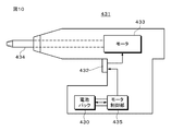
- the battery pack 430 and the motor control unit 435 are housed in the lower housing of the handle of the electric screwdriver 431.
- the battery pack 300 can be used as the battery pack 430.
- the motor control unit 435 controls the motor 433.
- Each part of the electric screwdriver 431 other than the motor 433 may be controlled by the motor control unit 435.
- the battery pack 430 and the electric screwdriver 431 are engaged with each other by engaging members provided therein.
- each of the battery pack 430 and the motor control unit 435 is provided with a microcomputer. Battery power is supplied from the battery pack 430 to the motor control unit 435, and information on the battery pack 430 is communicated between both microcomputers.
- the motor control unit 435 controls, for example, the rotation / stop of the motor 433 and the rotation direction. Further, the power supply to the load is cut off at the time of over-discharging.
- the trigger switch 432 is inserted between the motor 433 and the motor control unit 435, for example, and when the user pushes the trigger switch 432, power is supplied to the motor 433 and the motor 433 rotates. When the user returns the trigger switch 432, the rotation of the motor 433 is stopped.
- FIG. 11 is a plan view of an unmanned aerial vehicle.
- the airframe is composed of a cylindrical or square tubular body portion as a central portion and support shafts 442a to 442f fixed to the upper part of the body portion.
- the body portion has a hexagonal tubular shape, and six support shafts 442a to 442f extend radially from the center of the body portion at equiangular intervals.
- the body portion and the support shafts 442a to 442f are made of a lightweight and high-strength material.
- Motors 443a to 443f as drive sources for rotary blades are attached to the tips of the support shafts 442a to 442f, respectively.
- Rotor blades 444a to 444f are attached to the rotating shafts of the motors 443a to 443f.
- the circuit unit 445 including the motor control circuit for controlling each motor is attached to the central portion (upper part of the body portion) where the support shafts 442a to 442f intersect.
- the battery section as a power source is located at the lower position of the fuselage section.
- the battery section has three battery packs to supply power to a pair of motors and rotor blades having a 180 degree facing distance.
- Each battery pack has, for example, a lithium ion secondary battery and a battery control circuit that controls charging and discharging.
- the battery pack 300 can be used as the battery pack.
- the motor 443a and the rotary blade 444a and the motor 443d and the rotary blade 444d form a pair.
- FIG. 12 schematically shows an example of the configuration of a hybrid vehicle adopting the series hybrid system to which the present invention is applied.
- the series hybrid system is a vehicle that runs on a power driving force converter using the electric power generated by a generator powered by an engine or the electric power temporarily stored in a battery.
- the hybrid vehicle 600 includes an engine 601, a generator 602, a power driving force converter 603, a drive wheel 604a, a drive wheel 604b, a wheel 605a, a wheel 605b, a battery 608, a vehicle control device 609, various sensors 610, and a charging port 611. Is installed.
- the battery pack 300 of the present invention described above is applied to the battery 608.
- the hybrid vehicle 600 runs on the power driving force conversion device 603 as a power source.
- An example of the power driving force conversion device 603 is a motor.
- the electric power of the battery 608 operates the electric power driving force conversion device 603, and the rotational force of the electric power driving force conversion device 603 is transmitted to the drive wheels 604a and 604b.
- DC-AC DC-AC
- AC-DC conversion AC-DC conversion
- the power driving force conversion device 603 can be applied to both an AC motor and a DC motor.
- the various sensors 610 control the engine speed via the vehicle control device 609, and control the opening degree (throttle opening degree) of a throttle valve (not shown).
- the various sensors 610 include a speed sensor, an acceleration sensor, an engine speed sensor, and the like.
- the rotational force of the engine 601 is transmitted to the generator 602, and the electric power generated by the generator 602 by the rotational force can be stored in the battery 608.
- the resistance force at the time of deceleration is applied to the power driving force conversion device 603 as a rotational force, and the regenerative power generated by the power driving force conversion device 603 by this rotational force is the battery 608. Accumulate in.
- the battery 608 By connecting the battery 608 to an external power source of the hybrid vehicle 600, it is possible to receive electric power from the external power source using the charging port 611 as an input port and store the received electric power.
- an information processing device that performs information processing related to vehicle control based on information related to the secondary battery may be provided.
- an information processing device for example, there is an information processing device that displays the remaining battery level based on information on the remaining battery level.
- the present invention is also effective for a parallel hybrid vehicle in which the outputs of the engine and the motor are used as drive sources, and the three methods of traveling only by the engine, traveling only by the motor, and traveling by the engine and the motor are appropriately switched and used. Applicable. Further, the present invention can be effectively applied to a so-called electric vehicle that travels by being driven only by a drive motor without using an engine.
- Negative electrode current collector plate 26 ... through hole, 27, 28 ... outer edge, 41, 42 ... end, 43 ... groove, 52 ... pin, 53 ... flat plate Convex part, 55 ... pin, 56 ... flat part, 101 ... insulating layer
Landscapes
- Chemical & Material Sciences (AREA)
- Engineering & Computer Science (AREA)
- Chemical Kinetics & Catalysis (AREA)
- Electrochemistry (AREA)
- General Chemical & Material Sciences (AREA)
- Aviation & Aerospace Engineering (AREA)
- Materials Engineering (AREA)
- Manufacturing & Machinery (AREA)
- Combustion & Propulsion (AREA)
- Secondary Cells (AREA)
- Connection Of Batteries Or Terminals (AREA)
- Battery Electrode And Active Subsutance (AREA)
Abstract
L'invention concerne une batterie secondaire, dans laquelle : une électrode positive (21) a une section revêtue (21B) qui est revêtue d'une couche de matériau actif d'électrode positive et a également une section non revêtue de matériau actif d'électrode positive (21C), toutes deux étant disposées sur une feuille d'électrode positive en forme de courroie (21A) ; une électrode négative (22) a une section revêtue (22B) qui est revêtue d'une couche de matériau actif d'électrode négative et a également une section non revêtue de matériau actif d'électrode négative (22C), toutes deux étant disposées sur une feuille d'électrode négative en forme de courroie (22A) ; la section non revêtue de matériau actif d'électrode positive (21C) est reliée à un collecteur de courant d'électrode positive (24) au niveau d'une extrémité d'un enroulement d'électrode ; la section non revêtue de matériau actif d'électrode négative (22C) est reliée à un collecteur de courant d'électrode négative (25) au niveau de l'autre extrémité de l'enroulement d'électrode ; la section non revêtue de matériau actif d'électrode positive (21C) et/ou la section non revêtue de matériau actif d'électrode négative (22C) présentent des surfaces (41, 42) qui sont formées en se chevauchant l'une par rapport à l'autre par pliage vers l'axe central de la structure d'enroulement ; et une observation des sections transversales des sections non revêtues de matériau actif (21C, 22C) le long d'un plan qui contient ledit axe central révèle qu'au moins des sections des sections non revêtues de matériau actif à proximité de l'axe central sont pliées en de multiples plis.
Priority Applications (3)
| Application Number | Priority Date | Filing Date | Title |
|---|---|---|---|
| CN202080047979.1A CN114128023B (zh) | 2019-07-30 | 2020-07-21 | 二次电池、电池包、电子设备、电动工具、电动航空器及电动车辆 |
| JP2021536974A JP7287467B2 (ja) | 2019-07-30 | 2020-07-21 | 二次電池、電池パック、電子機器、電動工具、電動式航空機及び電動車両 |
| US17/581,286 US20220149444A1 (en) | 2019-07-30 | 2022-01-21 | Secondary battery, battery pack, electronic device, electric tool, electric aircraft, and electric vehicle |
Applications Claiming Priority (2)
| Application Number | Priority Date | Filing Date | Title |
|---|---|---|---|
| JP2019139813 | 2019-07-30 | ||
| JP2019-139813 | 2019-07-30 |
Related Child Applications (1)
| Application Number | Title | Priority Date | Filing Date |
|---|---|---|---|
| US17/581,286 Continuation US20220149444A1 (en) | 2019-07-30 | 2022-01-21 | Secondary battery, battery pack, electronic device, electric tool, electric aircraft, and electric vehicle |
Publications (1)
| Publication Number | Publication Date |
|---|---|
| WO2021020237A1 true WO2021020237A1 (fr) | 2021-02-04 |
Family
ID=74230270
Family Applications (1)
| Application Number | Title | Priority Date | Filing Date |
|---|---|---|---|
| PCT/JP2020/028295 WO2021020237A1 (fr) | 2019-07-30 | 2020-07-21 | Batterie secondaire, bloc-batterie, dispositif électronique, outil électrique, aéronef électrique et véhicule électrique |
Country Status (4)
| Country | Link |
|---|---|
| US (1) | US20220149444A1 (fr) |
| JP (1) | JP7287467B2 (fr) |
| CN (1) | CN114128023B (fr) |
| WO (1) | WO2021020237A1 (fr) |
Cited By (6)
| Publication number | Priority date | Publication date | Assignee | Title |
|---|---|---|---|---|
| WO2022158857A2 (fr) | 2021-01-19 | 2022-07-28 | 주식회사 엘지에너지솔루션 | Ensemble électrode et batterie, et bloc-batterie et véhicule le comprenant |
| WO2023054579A1 (fr) * | 2021-10-01 | 2023-04-06 | 株式会社村田製作所 | Batterie secondaire |
| WO2023090367A1 (fr) * | 2021-11-18 | 2023-05-25 | 株式会社村田製作所 | Batterie rechargeable, bloc-batterie, dispositif électronique, outil électrique, aéronef électrique et véhicule électrique |
| WO2023090370A1 (fr) * | 2021-11-18 | 2023-05-25 | 株式会社村田製作所 | Batterie secondaire, bloc-batterie, dispositif électronique, outil électrique, aéronef électrique et véhicule électrique |
| WO2023189636A1 (fr) * | 2022-03-28 | 2023-10-05 | 株式会社村田製作所 | Batterie secondaire, bloc-batterie, dispositif électronique, outil électrique, aéronef électrique, véhicule électrique, et procédé de fabrication de corps d'enroulement d'électrode pour batterie secondaire |
| WO2023189564A1 (fr) * | 2022-03-30 | 2023-10-05 | 株式会社村田製作所 | Batterie |
Citations (8)
| Publication number | Priority date | Publication date | Assignee | Title |
|---|---|---|---|---|
| JP2001028274A (ja) * | 1999-02-24 | 2001-01-30 | Sanyo Electric Co Ltd | 電気エネルギー蓄積素子 |
| JP2003022842A (ja) * | 2001-05-02 | 2003-01-24 | Ngk Insulators Ltd | リチウム二次電池 |
| JP2008166030A (ja) * | 2006-12-27 | 2008-07-17 | Sanyo Electric Co Ltd | 渦巻電極体の製造方法及びこれを用いた密閉型電池の製造方法 |
| JP2010257851A (ja) * | 2009-04-27 | 2010-11-11 | Toyota Motor Corp | 電池の製造方法 |
| WO2011001639A1 (fr) * | 2009-06-30 | 2011-01-06 | パナソニック株式会社 | Batterie secondaire à électrolyte non aqueux |
| JP2016532990A (ja) * | 2013-09-25 | 2016-10-20 | コミッサリア ア レネルジー アトミーク エ オ ゼネルジ ザルタナテイヴ | リチウム電池の電気化学バンドルの製造方法 |
| WO2017061066A1 (fr) * | 2015-10-05 | 2017-04-13 | ソニー株式会社 | Dispositif de mesure de quantité résiduelle, bloc-batterie, outil électrique, aéronef de type électrique, véhicule électrique et alimentation électrique |
| JP2019003789A (ja) * | 2017-06-14 | 2019-01-10 | オートモーティブエナジーサプライ株式会社 | リチウムイオン二次電池素子およびリチウムイオン二次電池 |
Family Cites Families (11)
| Publication number | Priority date | Publication date | Assignee | Title |
|---|---|---|---|---|
| JP2000268803A (ja) * | 1999-03-19 | 2000-09-29 | Nec Corp | 非水電解液二次電池 |
| JP3831595B2 (ja) * | 2000-09-26 | 2006-10-11 | 三洋電機株式会社 | 円筒型二次電池 |
| JP2002198100A (ja) * | 2000-12-26 | 2002-07-12 | Shin Kobe Electric Mach Co Ltd | 電 池 |
| JP2006012801A (ja) * | 2004-05-28 | 2006-01-12 | M & G Eco Battery Institute Co Ltd | 二次電池 |
| JP4222292B2 (ja) * | 2004-11-08 | 2009-02-12 | ソニー株式会社 | 二次電池 |
| JP2008218203A (ja) * | 2007-03-05 | 2008-09-18 | Sony Corp | 電極および電池 |
| JP2008243672A (ja) * | 2007-03-28 | 2008-10-09 | Toshiba Corp | 二次電池用捲回電極、リチウムイオン二次電池および二次電池パック |
| JP5326645B2 (ja) * | 2009-02-20 | 2013-10-30 | 新神戸電機株式会社 | リチウムイオンキャパシタ |
| JP5428988B2 (ja) * | 2010-03-25 | 2014-02-26 | トヨタ自動車株式会社 | 捲回電極体型電池とその製造方法及び車両及び機器及び電極捲回装置 |
| KR101484832B1 (ko) * | 2010-05-18 | 2015-01-20 | 도요타지도샤가부시키가이샤 | 비수전해액 2차 전지, 차량 및 전지 사용 기기 |
| JP6801722B2 (ja) * | 2016-12-16 | 2020-12-16 | 株式会社村田製作所 | 二次電池、電池パック、電動車両、電力貯蔵システム、電動工具および電子機器 |
-
2020
- 2020-07-21 JP JP2021536974A patent/JP7287467B2/ja active Active
- 2020-07-21 CN CN202080047979.1A patent/CN114128023B/zh active Active
- 2020-07-21 WO PCT/JP2020/028295 patent/WO2021020237A1/fr active Application Filing
-
2022
- 2022-01-21 US US17/581,286 patent/US20220149444A1/en active Pending
Patent Citations (8)
| Publication number | Priority date | Publication date | Assignee | Title |
|---|---|---|---|---|
| JP2001028274A (ja) * | 1999-02-24 | 2001-01-30 | Sanyo Electric Co Ltd | 電気エネルギー蓄積素子 |
| JP2003022842A (ja) * | 2001-05-02 | 2003-01-24 | Ngk Insulators Ltd | リチウム二次電池 |
| JP2008166030A (ja) * | 2006-12-27 | 2008-07-17 | Sanyo Electric Co Ltd | 渦巻電極体の製造方法及びこれを用いた密閉型電池の製造方法 |
| JP2010257851A (ja) * | 2009-04-27 | 2010-11-11 | Toyota Motor Corp | 電池の製造方法 |
| WO2011001639A1 (fr) * | 2009-06-30 | 2011-01-06 | パナソニック株式会社 | Batterie secondaire à électrolyte non aqueux |
| JP2016532990A (ja) * | 2013-09-25 | 2016-10-20 | コミッサリア ア レネルジー アトミーク エ オ ゼネルジ ザルタナテイヴ | リチウム電池の電気化学バンドルの製造方法 |
| WO2017061066A1 (fr) * | 2015-10-05 | 2017-04-13 | ソニー株式会社 | Dispositif de mesure de quantité résiduelle, bloc-batterie, outil électrique, aéronef de type électrique, véhicule électrique et alimentation électrique |
| JP2019003789A (ja) * | 2017-06-14 | 2019-01-10 | オートモーティブエナジーサプライ株式会社 | リチウムイオン二次電池素子およびリチウムイオン二次電池 |
Cited By (6)
| Publication number | Priority date | Publication date | Assignee | Title |
|---|---|---|---|---|
| WO2022158857A2 (fr) | 2021-01-19 | 2022-07-28 | 주식회사 엘지에너지솔루션 | Ensemble électrode et batterie, et bloc-batterie et véhicule le comprenant |
| WO2023054579A1 (fr) * | 2021-10-01 | 2023-04-06 | 株式会社村田製作所 | Batterie secondaire |
| WO2023090367A1 (fr) * | 2021-11-18 | 2023-05-25 | 株式会社村田製作所 | Batterie rechargeable, bloc-batterie, dispositif électronique, outil électrique, aéronef électrique et véhicule électrique |
| WO2023090370A1 (fr) * | 2021-11-18 | 2023-05-25 | 株式会社村田製作所 | Batterie secondaire, bloc-batterie, dispositif électronique, outil électrique, aéronef électrique et véhicule électrique |
| WO2023189636A1 (fr) * | 2022-03-28 | 2023-10-05 | 株式会社村田製作所 | Batterie secondaire, bloc-batterie, dispositif électronique, outil électrique, aéronef électrique, véhicule électrique, et procédé de fabrication de corps d'enroulement d'électrode pour batterie secondaire |
| WO2023189564A1 (fr) * | 2022-03-30 | 2023-10-05 | 株式会社村田製作所 | Batterie |
Also Published As
| Publication number | Publication date |
|---|---|
| JPWO2021020237A1 (fr) | 2021-02-04 |
| JP7287467B2 (ja) | 2023-06-06 |
| CN114128023B (zh) | 2024-03-29 |
| CN114128023A (zh) | 2022-03-01 |
| US20220149444A1 (en) | 2022-05-12 |
Similar Documents
| Publication | Publication Date | Title |
|---|---|---|
| WO2021020237A1 (fr) | Batterie secondaire, bloc-batterie, dispositif électronique, outil électrique, aéronef électrique et véhicule électrique | |
| WO2021020119A1 (fr) | Batterie secondaire, bloc-batterie, dispositif électronique, outil électrique, aéronef à alimentation électrique, et véhicule à propulsion électrique | |
| JP7074263B2 (ja) | 二次電池、電池パック、電子機器、電動工具、電動式航空機及び電動車両 | |
| WO2021020235A1 (fr) | Batterie secondaire, bloc-batterie, outil électrique, aéronef électrique et véhicule électrique | |
| WO2021176906A1 (fr) | Batterie secondaire, dispositif électronique et outil électrique | |
| WO2021177149A1 (fr) | Batterie secondaire, dispositif électronique et outil électrique | |
| US20220149441A1 (en) | Secondary battery, battery pack, electronic device, electric tool, electric aircraft, and electric vehicle | |
| US20220123372A1 (en) | Secondary battery, battery pack, electronic device, electric tool, electric aircraft, and electric vehicle | |
| WO2021024940A1 (fr) | Batterie secondaire, bloc-batterie, dispositif électronique, outil électrique, aéronef électrique et véhicule électrique | |
| WO2021020277A1 (fr) | Batterie secondaire, bloc-batterie, dispositif électronique, outil électrique, avion électrique et véhicule électrique | |
| WO2021153231A1 (fr) | Batterie secondaire, appareil électronique, et outil électrique | |
| WO2021153230A1 (fr) | Batterie secondaire, dispositif électronique et outil électrique | |
| WO2021020279A1 (fr) | Batterie secondaire, bloc-batterie, dispositif électronique, outil électrique, aéronef électrique et véhicule électrique | |
| US20230344094A1 (en) | Secondary battery, electronic equipment, and electric tool | |
| WO2022054642A1 (fr) | Batterie secondaire, appareil électronique et outil électrique | |
| WO2021149554A1 (fr) | Batterie secondaire, dispositif électronique et outil électrique | |
| WO2021149555A1 (fr) | Batterie secondaire, dispositif électronique et outil électrique |
Legal Events
| Date | Code | Title | Description |
|---|---|---|---|
| 121 | Ep: the epo has been informed by wipo that ep was designated in this application |
Ref document number: 20848207 Country of ref document: EP Kind code of ref document: A1 |
|
| ENP | Entry into the national phase |
Ref document number: 2021536974 Country of ref document: JP Kind code of ref document: A |
|
| NENP | Non-entry into the national phase |
Ref country code: DE |
|
| 122 | Ep: pct application non-entry in european phase |
Ref document number: 20848207 Country of ref document: EP Kind code of ref document: A1 |