WO2021019600A1 - レンズ制御装置およびレンズ制御方法 - Google Patents
レンズ制御装置およびレンズ制御方法 Download PDFInfo
- Publication number
- WO2021019600A1 WO2021019600A1 PCT/JP2019/029417 JP2019029417W WO2021019600A1 WO 2021019600 A1 WO2021019600 A1 WO 2021019600A1 JP 2019029417 W JP2019029417 W JP 2019029417W WO 2021019600 A1 WO2021019600 A1 WO 2021019600A1
- Authority
- WO
- WIPO (PCT)
- Prior art keywords
- time
- lens
- drive
- stepping motor
- period
- Prior art date
- Legal status (The legal status is an assumption and is not a legal conclusion. Google has not performed a legal analysis and makes no representation as to the accuracy of the status listed.)
- Ceased
Links
Images









Classifications
-
- G—PHYSICS
- G03—PHOTOGRAPHY; CINEMATOGRAPHY; ANALOGOUS TECHNIQUES USING WAVES OTHER THAN OPTICAL WAVES; ELECTROGRAPHY; HOLOGRAPHY
- G03B—APPARATUS OR ARRANGEMENTS FOR TAKING PHOTOGRAPHS OR FOR PROJECTING OR VIEWING THEM; APPARATUS OR ARRANGEMENTS EMPLOYING ANALOGOUS TECHNIQUES USING WAVES OTHER THAN OPTICAL WAVES; ACCESSORIES THEREFOR
- G03B5/00—Adjustment of optical system relative to image or object surface other than for focusing
- G03B5/04—Vertical adjustment of lens; Rising fronts
-
- H—ELECTRICITY
- H02—GENERATION; CONVERSION OR DISTRIBUTION OF ELECTRIC POWER
- H02P—CONTROL OR REGULATION OF ELECTRIC MOTORS, ELECTRIC GENERATORS OR DYNAMO-ELECTRIC CONVERTERS; CONTROLLING TRANSFORMERS, REACTORS OR CHOKE COILS
- H02P8/00—Arrangements for controlling dynamo-electric motors rotating step by step
- H02P8/40—Special adaptations for controlling two or more stepping motors
-
- G—PHYSICS
- G02—OPTICS
- G02B—OPTICAL ELEMENTS, SYSTEMS OR APPARATUS
- G02B7/00—Mountings, adjusting means, or light-tight connections, for optical elements
- G02B7/02—Mountings, adjusting means, or light-tight connections, for optical elements for lenses
- G02B7/04—Mountings, adjusting means, or light-tight connections, for optical elements for lenses with mechanism for focusing or varying magnification
- G02B7/08—Mountings, adjusting means, or light-tight connections, for optical elements for lenses with mechanism for focusing or varying magnification adapted to co-operate with a remote control mechanism
-
- G—PHYSICS
- G03—PHOTOGRAPHY; CINEMATOGRAPHY; ANALOGOUS TECHNIQUES USING WAVES OTHER THAN OPTICAL WAVES; ELECTROGRAPHY; HOLOGRAPHY
- G03B—APPARATUS OR ARRANGEMENTS FOR TAKING PHOTOGRAPHS OR FOR PROJECTING OR VIEWING THEM; APPARATUS OR ARRANGEMENTS EMPLOYING ANALOGOUS TECHNIQUES USING WAVES OTHER THAN OPTICAL WAVES; ACCESSORIES THEREFOR
- G03B3/00—Focusing arrangements of general interest for cameras, projectors or printers
- G03B3/10—Power-operated focusing
-
- G—PHYSICS
- G03—PHOTOGRAPHY; CINEMATOGRAPHY; ANALOGOUS TECHNIQUES USING WAVES OTHER THAN OPTICAL WAVES; ELECTROGRAPHY; HOLOGRAPHY
- G03B—APPARATUS OR ARRANGEMENTS FOR TAKING PHOTOGRAPHS OR FOR PROJECTING OR VIEWING THEM; APPARATUS OR ARRANGEMENTS EMPLOYING ANALOGOUS TECHNIQUES USING WAVES OTHER THAN OPTICAL WAVES; ACCESSORIES THEREFOR
- G03B5/00—Adjustment of optical system relative to image or object surface other than for focusing
-
- H—ELECTRICITY
- H02—GENERATION; CONVERSION OR DISTRIBUTION OF ELECTRIC POWER
- H02P—CONTROL OR REGULATION OF ELECTRIC MOTORS, ELECTRIC GENERATORS OR DYNAMO-ELECTRIC CONVERTERS; CONTROLLING TRANSFORMERS, REACTORS OR CHOKE COILS
- H02P8/00—Arrangements for controlling dynamo-electric motors rotating step by step
- H02P8/14—Arrangements for controlling speed or speed and torque
-
- G—PHYSICS
- G03—PHOTOGRAPHY; CINEMATOGRAPHY; ANALOGOUS TECHNIQUES USING WAVES OTHER THAN OPTICAL WAVES; ELECTROGRAPHY; HOLOGRAPHY
- G03B—APPARATUS OR ARRANGEMENTS FOR TAKING PHOTOGRAPHS OR FOR PROJECTING OR VIEWING THEM; APPARATUS OR ARRANGEMENTS EMPLOYING ANALOGOUS TECHNIQUES USING WAVES OTHER THAN OPTICAL WAVES; ACCESSORIES THEREFOR
- G03B2205/00—Adjustment of optical system relative to image or object surface other than for focusing
- G03B2205/0046—Movement of one or more optical elements for zooming
-
- G—PHYSICS
- G03—PHOTOGRAPHY; CINEMATOGRAPHY; ANALOGOUS TECHNIQUES USING WAVES OTHER THAN OPTICAL WAVES; ELECTROGRAPHY; HOLOGRAPHY
- G03B—APPARATUS OR ARRANGEMENTS FOR TAKING PHOTOGRAPHS OR FOR PROJECTING OR VIEWING THEM; APPARATUS OR ARRANGEMENTS EMPLOYING ANALOGOUS TECHNIQUES USING WAVES OTHER THAN OPTICAL WAVES; ACCESSORIES THEREFOR
- G03B2205/00—Adjustment of optical system relative to image or object surface other than for focusing
- G03B2205/0053—Driving means for the movement of one or more optical element
-
- G—PHYSICS
- G03—PHOTOGRAPHY; CINEMATOGRAPHY; ANALOGOUS TECHNIQUES USING WAVES OTHER THAN OPTICAL WAVES; ELECTROGRAPHY; HOLOGRAPHY
- G03B—APPARATUS OR ARRANGEMENTS FOR TAKING PHOTOGRAPHS OR FOR PROJECTING OR VIEWING THEM; APPARATUS OR ARRANGEMENTS EMPLOYING ANALOGOUS TECHNIQUES USING WAVES OTHER THAN OPTICAL WAVES; ACCESSORIES THEREFOR
- G03B2205/00—Adjustment of optical system relative to image or object surface other than for focusing
- G03B2205/0053—Driving means for the movement of one or more optical element
- G03B2205/0084—Driving means for the movement of one or more optical element using other types of actuators
Definitions
- the present invention relates to a lens control device and a lens control method capable of controlling a plurality of lenses independently and displaying and / or recording a live view image or a moving image during zooming.
- the imaging device disclosed in Patent Document 1 includes a DC motor A (DCMA) for driving the zoom lens A, a stepping motor B (STMB) for driving the zoom lens B, and an STMC for driving the focus lens C. ..
- DCMA DC motor A
- STMB stepping motor B
- STMC STMC for driving the focus lens C.
- the STMB is driven in synchronization with the position detection pulse of DCMA, and the position of the lens B is confirmed for each position detection pulse.
- the normal synchronous drive amount is usually driven by one pulse, and when the position of the lens B is shorter than the predetermined distance and the distance between the STMB and the lens A is widened, the synchronous drive amount of the STMB is the normal synchronous drive amount (The drive speed is accelerated by changing from (1 pulse drive) to a high-speed synchronous drive amount (3 pulse drive). By performing such drive control, it is possible to prevent the lens groups from interfering with each other and deviating from each other, and it is possible to prevent step-out.
- Patent Document 1 controls each lens position so as to approach a predetermined position within a predetermined section during zoom drive.
- Patent Document 1 only discloses that interference between lenses is prevented, and by ensuring the accuracy of each lens position during zoom drive, the appearance of a live view image or a moving image is improved. There is no mention of improvement.
- the present invention has been made in view of such circumstances, and is a lens control device that ensures the accuracy of the lens position while driving the lens and improves the appearance of the live view image and / or the moving image image. It is an object of the present invention to provide a lens control method.
- the lens control device includes a first stepping motor for driving a zoom lens included in the photographic lens in a lens control device having a photographic lens capable of zooming and focusing.
- the drive time is set according to a predetermined control unit time for each drive pulse of the second stepping motor for driving the focus lens included in the photographing lens and the first stepping motor and the second stepping motor. It is possible, and the first stepping motor and the control unit for controlling the second stepping motor are provided, and the first stepping motor and the first stepping motor are provided within a period in which the zoom lens and the focus lens drive a predetermined section.
- the control unit has a period for driving at least one of the second stepping motors at a constant speed, and the control unit sets the time required to move the predetermined section with a predetermined number of pulses as a predetermined time.
- the driving time obtained by dividing the driving time of all the driving pulses in the driving period by the number of pulses in that period is taken as the average driving time
- the driving period at a constant speed is divided into a plurality of periods
- the average driving time is divided into a plurality of periods.
- a lens control device characterized in that a plurality of the driving times sandwiching the lens are set to the driving pulses of the plurality of periods.
- the lens control device divides the variable range of the zoom position of the zoom lens into a plurality of sections, and at least one of the plurality of sections.
- the shortest time that the zoom lens and the focus lens can move in the section is calculated, and if at least one of the shortest times exceeds the predetermined reference time, the predetermined time is extended.
- the control unit sets the shortest time exceeding the predetermined reference time as the predetermined time.
- the lens control device has a third stepping motor for driving the second zoom lens included in the photographing lens, and the control unit is the first stepping motor.
- the zoom lens, the focus lens, and the second zoom lens define a predetermined section.
- the period of driving at the constant speed is divided into a plurality of periods, and the plurality of driving times sandwiching the average time are divided into the driving pulses of the plurality of periods.
- the lens control method drives a photographing lens capable of zooming and focusing, a first stepping motor for driving the zoom lens included in the photographing lens, and a focus lens included in the photographing lens.
- the drive time can be set according to a predetermined control unit time for each drive pulse of the first stepping motor and the second stepping motor.
- the zoom has a period of driving at least one of the first stepping motor and the second stepping motor at a constant speed.
- the drive times of all the drive pulses in the period of driving at the constant speed are divided by the number of pulses in that period.
- the drive time is set to the average drive time
- the period of driving at the constant speed is divided into a plurality of periods, and the plurality of drive times sandwiching the average drive time are set to the drive pulses of the plurality of periods.
- the lens control device is a lens control device having a photographing lens capable of zooming and focusing, and includes a first stepping motor for driving the zoom lens included in the photographing lens and the photographing lens.
- the drive time can be set according to a predetermined control unit time for each drive pulse of the second stepping motor that drives the focus lens, the first stepping motor, and the second stepping motor.
- a control unit for controlling one stepping motor and a second stepping motor is provided, and the control unit drives the zoom lens and the focus lens in parallel in a predetermined section between their respective predetermined positions.
- the drive time of the drive pulse is set so that the times are the same.
- the present invention it is possible to provide a lens control device and a lens control method that ensure the accuracy of the lens position while driving the lens and improve the appearance of the live view image and / or the moving image.
- This camera has an imaging unit, the subject image is converted into image data by the imaging unit, and the subject image is displayed in a live view on a display unit arranged on the back surface of the main body based on the converted image data.
- the photographer determines the composition and shutter timing by observing the live view display.
- the image data is recorded on the recording medium.
- the image data recorded on the recording medium can be reproduced and displayed on the display unit when the reproduction mode is selected.
- this camera controls the position by driving a zoom lens, a focus lens, and a correction lens (for example, for correcting curvature of field) with individual stepping motors.
- the area between the wide end and the tele end of the zoom lens is finely divided into predetermined "sections" (see FIG. 6).
- Each stepping motor adjusts the time by controlling the pulse applied to the stepping motor in order to drive each section with the above-mentioned fixed drive time (“fixed drive time”).
- the acceleration period and deceleration period of the stepping motor cannot be used for time adjustment due to load and motor characteristic restrictions, so the time is adjusted in a constant speed period.
- the time is adjusted by pulse distribution of "two drive times" determined by the control resolution sandwiching the "average drive time” which is the ideal drive time, and the error of the actual operation with respect to the "determined drive life time” is suppressed ( For example, see FIGS. 18 to 22 described later).
- FIG. 1 is a block diagram showing a mainly electrical configuration of the camera 1 according to the embodiment of the present invention.
- the camera 1 includes a main unit 100 and a mirror frame unit 200.
- the mirror frame unit 200 and the main unit 100 may be configured separately, but here, it will be described as being integrally configured.
- the mirror frame unit 200 includes a zoom lens 250, a focus lens 253, and a correction lens 254 as photographing lenses.
- the zoom lens 250 is moved in the optical axis direction by the lens driving mechanism A205, and the focal length is adjusted.
- the focus lens 253 is moved in the optical axis direction by the lens driving mechanism B230, and the focus is adjusted.
- the correction lens 254 is moved in the optical axis direction by the lens driving mechanism C240, and optical aberration (for example, curvature of field aberration) is corrected.
- the lens drive mechanism A205, the lens drive mechanism B230, and the lens drive mechanism C240 have a stepping motor as a mechanism for moving each lens and a drive source. Details of these drive mechanisms will be described later with reference to FIG.
- Aperture 251 and shutter 252 are arranged on the optical axis of the zoom lens 250, the focus lens 253, and the correction lens 254.
- the aperture diameter of the diaphragm 251 is changed by the diaphragm drive mechanism 210 in order to adjust the amount of light of the light flux passing through the photographing lens.
- the aperture 251 When the aperture state is unknown, such as immediately after the power is turned on, the aperture 251 once drives the stepping motor step by step from the maximum aperture state to the open state. By this drive, the aperture can be set to the open position regardless of the aperture state. This operation is called “aperture reset drive". After opening once, the aperture state is managed by counting the number of driven steps based on the opening position.
- the shutter 252 adjusts the time of the light flux passing through the photographing lens by the shutter drive mechanism 220.
- the shutter 252 is driven by a moving magnet coil (not shown) provided in the shutter drive mechanism 220.
- the shutter 252 is controlled by an H-bridge circuit provided in the motor driver IC 120, and when energized in one direction, the shutter 252 is opened, and when energized in the opposite direction, light is shielded.
- the lens drive mechanism A205, the aperture drive mechanism 210, the shutter drive mechanism 220, the lens drive mechanism B230, and the lens drive mechanism 240 are connected to the motor driver IC 120 arranged in the main unit 100.
- the motor driver IC 120 receives signals such as lens position information from the lens drive mechanism A205, the lens drive mechanism B230, and the lens drive mechanism C240, and outputs these information to the control microcomputer 101.
- the motor driver IC 120 is a drive circuit for driving actuators such as a lens drive mechanism A205, an aperture drive mechanism 210, a shutter drive mechanism 220, a lens drive mechanism B230, and a stepping motor arranged in the lens drive mechanism C240.
- the stepping motor has an H-bridge circuit, etc.) and controls the drive of actuators such as stepping motors in response to control signals from the control microcomputer 101.
- the driving method of the stepping motor is to change the excitation state for each edge (or one pulse) of the clock, and drive the stepping motor by an amount corresponding to the clock.
- the excitation state of the stepping motor changes by one step, and the motor shaft is rotationally driven by one step.
- the unit indicating the amount of movement of the lens will be described as “pulse”.
- the stepping motor provided in the lens drive mechanism A205 functions as a first stepping motor for driving the zoom lens 250 included in the photographing lens. Further, the stepping motor provided in the lens driving mechanism B230 functions as a second stepping motor for driving the focus lens 253 included in the photographing lens.
- the drive time can be set for each drive pulse of the first stepping motor and the second stepping motor according to a predetermined control time unit.
- the lens driving mechanism C240 functions as a third stepping motor that drives the correction lens 254 included in the photographing lens. In the case of a photographing lens including the first and second zoom lenses, the third stepping motor may drive the second zoom lens.
- a third and fourth stepping motors for driving the respective lenses may be arranged.
- the image sensor 111 is arranged in the main unit 100 near a position where a subject image is formed on the optical axis of the photographing lens.
- the image sensor 111 is an image sensor such as a CCD image sensor or a CMOS image sensor.
- photodiodes are arranged two-dimensionally, and each photodiode performs photoelectric conversion of a subject image and outputs a photoelectric conversion signal (analog signal).
- the image sensor 111 is connected to the image sensor drive IC 110, and the image sensor IC 110 controls the exposure time of the image sensor 111 and reads out a photoelectric conversion signal (analog signal).
- the image pickup device IC 110 performs processing such as AD conversion on the read photoelectric conversion signal and outputs it to the image processing IC 102.
- the image processing IC 102 generates image data from the image signal output from the image sensor drive IC, and stores the generated image data in the SDRAM (Synchronous Dynamic Random Access Memory) 103. In generating image data, various image processing such as exposure compensation, noise processing, WB (White Balance) gain correction, contour enhancement, and false color correction are performed. Further, the image processing IC 102 also performs a process (development processing) of converting the image data subjected to the above-mentioned image processing into a recording data format.
- SDRAM Synchronous Dynamic Random Access Memory
- the image data processed for recording by the image processing IC 102 is recorded on the recording medium 131 through the communication connector 130.
- the recording medium 131 is a recording medium that can be inserted into and removed from the main unit 100, and the communication connector 130 can record image data on the recording medium and can read the image data.
- the image data processed by the image processing IC 102 for live view display or playback display is output to the liquid crystal monitor 140, and the liquid crystal monitor 140 displays the image.
- An image such as a menu image is also displayed on the liquid crystal monitor 140.
- the liquid crystal monitor 140 is not limited to the liquid crystal display, and may be another display monitor such as an organic EL monitor.
- the operation member 150 is a user interface for the user to instruct the camera 1, and includes a switch, a dial, a touch panel, and the like and a detection circuit thereof.
- Examples of the operation member 150 include a power on / off switch, a release button, a zoom operation switch, a touch panel arranged on the front surface of the liquid crystal monitor 140, and the like.
- the zoom operation switch has a neutral position, a wide side position, and a tele side position, and the zoom operation is performed by the user turning on the wide side position or the tele side position of the zoom operation switch.
- the control microcomputer 101 is a processor having a CPU (Central Processing Unit), its peripheral circuits, memory, and the like.
- the CPU executes the entire camera by controlling each part in the camera 1 according to a program stored in the memory. For example, based on the power-on signal from the operating member 150, the control microcomputer 101 starts the operation of the camera 1 and displays the live view image on the liquid crystal monitor 140. Further, based on the half-press operation signal of the release button, the control microcomputer 101 executes a focusing operation, a calculation for proper exposure, and the like.
- the control microcomputer 101 drives the zoom lens 250 in the zoom direction (wide side position or tele side position) of the operated switch by the lens drive mechanism A205. Further, in accordance with the movement of the zoom lens 250, the control microscope 101 sets the correction lens 254 at a position where the focus lens 253 is maintained at the subject distance (the distance from the camera to the focus position). To a position where it can be corrected appropriately.
- the control microcomputer 101 has functions such as a counting unit, a mode setting unit, a detection unit, a determination unit, and a calculation unit, in addition to a control unit that controls the overall operation of the camera.
- the control microcomputer 101 is connected to a motor driver IC 120, a camera operation switch (SW) 150, and a power supply (not shown).
- the control microcomputer 101 functions as a control unit that controls a first stepping motor that drives the zoom lens and a second stepping motor that drives the focus lens.
- the first stepping motor and the second stepping are performed within the period in which the zoom lens and the focus lens drive a predetermined section (see the fixed section time dt in FIG. 12 and the target drive time Tmov_tar in FIG. 22). It has a period for driving at least one of the motors at a constant speed (see, for example, a constant speed period Tc in FIGS. 19 and 22).
- This control unit drives all the drive pulses during the period of driving at a constant speed in order to set the time required to move the predetermined section with a predetermined number of pulses as a predetermined time (see, for example, the fixed section time td in FIG. 12).
- the drive time obtained by dividing the time by the number of pulses in that period is taken as the average drive time
- the period for driving at a constant speed is divided into multiple periods, and the multiple drive times with the average drive time in between are the drive pulses for multiple periods. (See, for example, FIGS. 19 and 22).
- control unit divides the variable range of the zoom position of the zoom lens into a plurality of sections, and calculates the shortest time that the zoom lens and the focus lens can move within the section for at least one of the plurality of sections. If at least one of the shortest time exceeds the predetermined reference time, the predetermined time is extended (see, for example, S33 in FIG. 11 and FIG. 12 (b)). The control unit sets the shortest time exceeding the predetermined reference time as the predetermined time (see, for example, S33 in FIG. 11 and FIG. 12B).
- control unit has a period for driving at least one of the first stepping motor, the second stepping motor, and the third stepping motor at a constant speed, and has the zoom lens, the focus lens, and the first stepping lens.
- the period of driving at a constant speed is divided into a plurality of periods, and a plurality of periods having an average time are sandwiched.
- the drive time of is set to drive pulses of a plurality of periods (see, for example, FIGS. 19 and 22).
- the third stepping motor drives the correction lens 254, but the present invention is not limited to this, the third stepping motor drives the second zoom lens, and the control unit drives the third stepping motor. May be controlled. Further, the control unit sets the drive time of the drive pulse so that the drive time for the zoom lens and the focus lens to be driven in parallel in a predetermined section between the respective predetermined positions is the same (for example, FIG. 22). reference).
- the control microcomputer 101 causes the image processing IC 102 to input image data from the image sensor driving IC 110.
- the image processing IC 102 saves the input image data in the SDRAM 104, which is a temporary storage memory.
- the SDRAM 104 is also used as a work area for image processing by the image processing IC 102.
- the image processing IC 102 can perform image processing for converting image data into JPEG data, and can store the converted image data in the recording medium 131.
- the image sensor 111 continuously exposes a subject image at a rate of, for example, about 30 images per second.
- the image sensor drive IC 110 outputs the image data photoelectrically converted by the image sensor 111 to the image processing IC 102, and the image processing IC 102 converts the image data into a video signal and outputs the image data to the liquid crystal monitor 140.
- the liquid crystal monitor 140 displays a moving image of the subject. Such a display is called “live view” and is well known.
- the user may select the live view mode by operating the mode change switch in the operation member 150.
- the live view may be abbreviated as "LV".
- the luminous flux transmitted through the zoom lens 250, the focus lens 253, and the correction lens 254 in the mirror frame unit 200 is always guided to the image sensor 111. Since the photoelectric conversion output of the image sensor 111 is output to the image sensor drive IC 110, the image data output from the image sensor drive IC 110 can perform photometric processing according to the brightness of the subject and distance measurement processing according to the distance of the subject.
- the image processing IC 102 may perform the operation based on the above. Based on the image data that is photoelectrically converted by the image sensor 111 and output from the image sensor drive IC 110, the light metering process and the distance measurement / automatic focusing process performed by the image processing IC 102 and the control microcomputer 101 are performed by "LV", respectively. It is referred to as "photometer” and "LVAF".
- FIG. 2 shows a drive mechanism for driving the focus lens 253
- the lens drive mechanism A205 for driving the zoom lens 250 and the lens drive mechanism C240 for driving the correction lens 254 also have the same configuration.
- the focus lens 253 is held by the frame 236, and a hole is provided in the lower part of the frame 236, and the screw 232 penetrates through this hole.
- the screw 232 is arranged along the optical axis direction of the focus lens 253.
- the image pickup side of the lower part of the frame 236 is urged to the image pickup side by the spring 235, and the nut 231 is screwed into the screw 232. Therefore, the frame 236 that holds the focus lens 253 is in a position where it engages with the nut 231 by the urging force of the spring 235.
- the end of the screw 232 on the object side is fixed to the rotating shaft of the stepping motor 233. Therefore, when the stepping motor 233 rotates, the screw 232 rotates, and the position of the nut 231 also moves. When the position of the nut 231 moves, the frame 236 holding the focus lens 253 also moves in the optical axis direction.
- the bottom surface of the above-mentioned frame 236 is a reflective surface 238. Further, the position sensor 237 is arranged within the moving range of the frame 236. The position sensor 237 and the stepping motor 233 are connected to the motor driver IC 120. The position sensor 237 has a light emitting unit and a light receiving unit, and when the projected light from the light emitting unit is reflected by the reflecting surface 238, it can be detected by the light receiving unit.
- the frame 236a shows the frame 236 at the reference position.
- the position sensor 237 receives the reflected light from the reflecting surface 238. Since the reflecting surface 238 has a certain area, an edge is generated in the signal based on the reflected light. In this embodiment, the right edge is used as a reference.
- the time point when the position sensor 237 detects the right edge of the signal is set as the reference position, and the position of the focus lens 253 is managed by the number of pulses from the reference position. For example, in the example shown in FIG.
- the control microcomputer 101 manages the position assuming that the focus lens position is at the position of "50 pulses", and the "number of pulses" driven from the reference position is expressed as "absolute pulse value (unit is pls)”. ) ”.
- the position of the lens can be determined by using the same method.
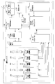
- This flowchart (the same applies to the flowcharts shown in FIGS. 11 and 18) is realized by the CPU in the control microcomputer 101 controlling each part in the camera 1 based on the program stored in the memory.
- the setup is performed first (S1).
- the control microprocessor 101 controls the mirror frame unit 200 so that the live view operation is possible.
- the zoom lens 250, the focus lens 253, and the correction lens 254 are driven to the reference lens position. Specifically, all the lenses are driven toward the imaging side until the position sensor 237 (see FIGS. 2 and 3) detects the reflected light from the reflecting surface 238. After that, it is driven to a predetermined zoom position.
- the zoom position (zoom position) is divided into 100 stages, and at the time of setup, it is set to the third position among the 100 stages of zoom positions (see FIG. 5). Further, the shutter 252 is opened, and the aperture 251 is set to the open state by performing the above-mentioned "reset drive".
- the above-mentioned "live view display” is started (S3).
- the above-mentioned "LV metering” and the live view exposure are updated (S5).
- the image processing IC 102 causes the image sensor drive IC 110 to change the amplification factor (ISO sensitivity) so that the exposure for live view becomes appropriate, and also controls the micro.
- the computer 101 changes the aperture value (AV value) of the aperture 251.
- the above-mentioned "LVAV” is performed, and the focus lens 253 is moved so that the subject is in focus.
- the control microcomputer 101 determines whether or not the zoom operation switch in the operation member 150 is turned on to either the tele side or the wide side.
- step S9 the lens position at each zoom position (Zp) is calculated (S9).
- the control microcomputer 101 calculates the position of each lens at each zoom position from the current position to the tele end (or wide end). Details of the calculation of the lens position will be described later with reference to FIGS. 5 to 7.
- step S9 the lens position at each Zp is calculated.
- the lens driving speed between each Zp and the next Zp, that is, in each section is calculated.
- the driving speed of the lens is determined by the time of the pulse applied to the stepping motor. The longer the drive time for each pal, the lower the speed.
- the section speed is adjusted so that the zoom lens 250, the focus lens 253, and the correction lens 254 reach each Zp at substantially the same timing (see FIG. 8).
- the details of the section velocity are calculated for all sections (100 sections in this embodiment). The detailed calculation of the section speed will be described later with reference to FIGS. 8 to 11.
- the lens is driven next (S13).
- the control microcomputer 101 drives the zoom lens 250, the focus lens 253, and the correction lens 254 by the motor driver IC 120 based on the section speed calculated in step S11.
- the section speed is calculated for the entire section, so that the control microcomputer 101 uses the zoom lens based on the section speed calculated in advance according to the section to which the zoom lens 250 belongs. It controls the drive of the 250, the focus lens 253, and the correction lens 254.
- the control microcomputer 101 determines whether or not the zoom operation switch in the operation member 150 is turned off. As a result of this determination, if the zoom operation switch is on, the process returns to step S13, and the control microcomputer 101 continues to drive the zoom lens 250, the focus lens 253, and the correction lens 254.
- the stop zoom position is determined (S17).
- the control microcomputer 101 determines a stoptable zoom position close to the current position. From the Zp that can stop zooming, which is determined in consideration of the usability of the camera, the Zp that is in the zoom drive direction and is closest to the current position is determined. For example, it is determined in advance that the Zp that can be stopped is a multiple of 3 other than the telephoto end. That is, when it is decided to set Zp0,3,6,9,12,15,18,21,24 ... 93,96,100 to the stop position, the zoom operation is performed while zooming in the tele direction from Zp3. If Zp at the time when is turned off is Zp16, the stop position is determined to be Zp18. If the zoom operation is not turned off even after reaching Zp96, Zp100 is determined as the stop position at that time.
- the detailed calculation of the section speed is performed (S19).
- the detailed calculation of the section speed is recalculated for the section immediately before the stop zoom position.
- the section recalculated here will be referred to as a "stop section”. The detailed calculation of the section speed will be described later with reference to FIGS. 8 to 11.
- the lens is driven until the stop section is reached (S21).
- the control microcomputer 101 drives the zoom lens 250, the focus lens 253, and the correction lens 254 by the motor driver IC 120 based on the section speed calculated in step S19.
- step S23 it is determined whether or not it is a stop section (S23).
- the lens drive stop process is performed (S25).
- the control microcomputer 101 executes a process for stopping the driving of the zoom lens 250, the focus lens 253, and the correction lens 254 by the motor driver IC 120.
- the excitation of the stepping motor is turned off after the last one pulse drive of the stop section.
- a stepping motor needs to be excited for a predetermined time before and after driving, but the description thereof is omitted in the present embodiment.
- the lens drive stop process is completed by stopping all the photographing lenses.
- step S27 If the lens stop process is executed in step S25, or as a result of the determination in step S7, the zoom operation switch is off, it is determined whether or not the power switch is off (S27).
- the control microcomputer 101 determines whether or not the power switch in the operating member 150 is off. As a result of this determination, if the power switch is on, the process returns to step S5 and the above-described operation is executed. On the other hand, when the power switch is off, the operation of this flow ends.
- each Zp the position at each zoom position (each Zp) is calculated for each lens (S9). Then, for each of the zoom lens 250, the focus lens 253, and the correction lens 254, the drive speed is calculated for each interval (section) between the zoom positions (S11). When each drive speed is calculated, the drive of each lens is controlled based on the calculation result (S13).
- the position of the zoom lens 250 corresponds to Zp, and the relationship table between the absolute position of the lens and each Zp is prepared in advance and stored in the memory in the control microcomputer 101.
- zoom positions Zp0 to Zp100 are provided between the wide end and the tele end.
- the position of the zoom lens is a000 to a100 in terms of absolute pulse value.
- the position of the focus lens 253 is determined by Zp and the position where the subject position is in focus.
- Zp (corresponding to the focal length) and the subject distance (distance from the lens to the subject position) are optically calculated from the current focus lens position and the imaging position. Since the method of calculating the subject distance is known, it is omitted. In the embodiment, the calculated subject distance will be described using an example of 60 cm.
- the lens position at this time is b0003.
- the position of the correction lens 254 is the current position c003.
- the current zoom position (Zp3) stored in the memory in the control microcomputer 101 is read and used for the zoom lens 250.
- the positions of the focus lens 253 and the correction lens 254 in Zp3 are also read from the memory and used.
- the other lens positions b000 to b002, b004 to b100, and c000 to c002, c004 to c100 are calculated by the control microcomputer 101.
- the absolute pulse values are b000 to b002 and b004 to b100.
- the position of the correction lens 254 corresponding to each of the other focal positions (zoom position Zp) is set to a "predetermined position (absolute pulse value)" for each Zp and a "predetermined predetermined amount" according to the subject distance. Is added or subtracted. For example, if the subject distance is less than 30 cm, +1 pulse is used, and if it is 30 cm or more, no addition is performed. Expressed as an absolute pulse value, it is c000 to c002 and c004 to c100.
- step S9 all lens positions in each Zp are determined.
- FIG. 6 shows the relationship between the zoom position Zp and the section. As described above, a total of 101 zoom positions Zp of zoom positions Zp0 to Zp100 are provided between the wide end and the tele end, and sections 0 to 99 are arranged between these zoom positions Zp. ..
- FIG. 7 shows the interval pulse values ([pls]) of each lens.
- Each interval pulse value is the difference between the absolute pulse positions ([pls]) of the adjacent zoom positions Zp.
- the section pulse value in section 0 of the zoom lens 250 is the difference value ad000 between the absolute pulse position a000 at the zoom position Zp0 and the absolute pulse value a001 at the zoom position Zp1.
- the section pulse values ad000 to ad099 from the section 0 to the section 99 can be obtained.
- the interval pulse values bd000 to bd099 from the interval 0 to the interval 99 can be obtained.
- the interval pulse value of the focus lens 253 changes greatly depending on the subject distance.
- the interval pulse values cd000 to cd099 from the interval 0 to the interval 99 can be obtained.
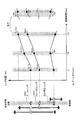
- the vertical axis shows the positions of the zoom lens 250, the focus lens 253, and the correction lens 254, and the horizontal axis shows the flow of time.
- the zoom position Zp of the zoom lens 250 is at the position X at the time T1, and the focus lens 253 at that time is in the position where the subject distance is 60 cm. Further, the correction lens 254 is also driven to a position where the optical aberration is removed.
- the zoom position Zp of the zoom lens 250 is at position X + 1, and the focus lens 253 is also driven so as to be in focus at a subject distance of 60 cm.
- the zoom position Zp of the zoom lens 250 is at position X + 2, and the focus lens 253 is also driven to a position in focus at a subject distance of 60 cm.
- FIG. 8 illustrates an example in which the driving direction of the correction lens 254 is reversed at time T2.
- the stepping motor is stopped for a predetermined time before reversing in order to suppress sudden load fluctuations when reversing.
- the control microcomputer 101 instructs the motor driver IC 120 to drive in the reverse direction.
- the correction lens 254 is stopped only for the time t2c and then driven in the reversing direction.
- the stop time at the time of reversal is also taken into consideration in order not to cause the waiting time of each of the plurality of lenses.
- Each lens is driven and controlled so that the zoom positions ZpX, ZpX + 1, ZpX + 2, etc. are at the pre-calculated lens positions (target positions) at the same predetermined time.
- Drive control in this way is called cooperative drive.
- the problem when the cooperative drive is not performed will be described.
- FIG. 8 as shown in the enlarged view at the time T3, if there is a difference in the time to reach each target position at the zoom position position Zp or the like, in order to wait for the arrival of another lens with respect to the time T3. , Meeting time occurs.
- FIG. 8 As shown in the enlarged view at the time T3, if there is a difference in the time to reach each target position at the zoom position position Zp or the like, in order to wait for the arrival of another lens with respect to the time T3. , Meeting time occurs.
- the zoom lens 250 has a waiting time t3a
- the correction lens 254 has a waiting time t3c.
- the waiting time as shown in the enlarged view of FIG. 8 occurs, the image captured in the period t3a is captured during the period t3a because the position of the focus lens 253 or the position of the correction lens 254 has not reached the target position.
- the image quality of (live view image / moving image) deteriorates. Therefore, in order to improve the image quality, each lens reaches each target position at a predetermined same time so that the waiting times t3a and t3c shown in the enlarged view of FIG. 8 do not occur at each zoom position Zp. It is preferable to drive.
- step S11 see FIG. 4
- the drive speed of each lens is adjusted so that the waiting time does not occur, and the cooperative drive is performed.
- the rule for changing the speed is that when changing the speed across the "acceleration / deceleration stage", the "number of pulses required for acceleration / deceleration” is driven at the speed of the "acceleration / deceleration stage” (driving time for each pulse). ..
- the "acceleration / deceleration stage” and the “number of pulses required for acceleration / deceleration” are determined in advance in terms of mechanical design from the characteristics of the stepping motor, the load applied to the stepping motor, and the application (whether quiet priority or speed priority).
- FIGS. 9 and 10 the difference in control depending on the "number of pulses required for acceleration / deceleration" will be described in the case of having an acceleration / deceleration stage.
- the example shown in FIGS. 9 and 10 has a plurality of acceleration / deceleration stages 1 and 2 in the control for setting the drive time for each pulse.
- FIG. 9 shows the control when the “number of pulses required for acceleration / deceleration” at the time of speed switching is one pulse.
- the pls number 1 to 6 indicating the number of the pulse driving the stepping motor is included in the interval n
- the pls numbers 7 to 12 are included in the interval n + 1. (Pls 13 to 25 have the same meaning, so the description thereof will be omitted).
- Section n + 1 in FIG. 9 shows a case where the average speed of pls numbers 7 to 12 is higher than the speed of pls number 6 in section n and is driven at a higher speed across the acceleration / deceleration stage 1.
- the stepping motor is driven by applying the first pulse (pls number 7) of the section n + 1 from the last pulse (pls number 6) of the section n, one pulse of the pls number 7 is applied across the acceleration / deceleration stage. It is driven by the "driving time for each pulse" of the acceleration / deceleration stage 1.
- the remaining pulses (pls numbers 8 to 12) are driven at a constant speed faster than the "acceleration / deceleration stage 1".
- Section n + 2 is a case of driving at a speed slower than that of "acceleration / deceleration stage 2", and is driven by one pulse of pls numbers 13 and 14 as acceleration / deceleration stage 1 and acceleration / deceleration stage 2, respectively.
- the section n + 3 shows the case of control immediately before stopping. The speed is increased, but in the final pulse (pls number 25) of the section n + 3, the speed is set to the slowest acceleration / deceleration stage "acceleration / deceleration stage 2". This is a control example in which the vehicle can be stopped after the pls number 25 (since there is no acceleration / deceleration stage straddling the acceleration / deceleration stages 2 to the stop).
- FIG. 10 shows the control when the “pulse required for acceleration / deceleration” is 2 pulses when the speed is switched.
- the number of pulses driven by the 10 acceleration / deceleration stage 1 or the acceleration / deceleration stage 2 is different from that of 2 pulses as compared with the case of FIG. 9 (pls numbers 7 and 8).
- the shortest controllable time is calculated (S31).
- the minimum time that the zoom lens 250, the focus lens 253, and the correction lens 254 can drive the number of pulses in each section is different. As described with reference to FIG. 8, it is desirable from the viewpoint of ensuring image quality that each lens reaches a predetermined position at the same time at the zoom position Zp of each section.
- this step calculates the shortest controllable time. The calculation in the shortest time will be described later with reference to FIGS. 15 to 17.
- the time of the final section is then calculated (S33).
- the section time set for driving the section is read from the table (see “Section time_table value” in FIG. 14 described later), and the shortest time of all lenses obtained in step S31 and this section Calculate the final interval time based on the time.
- the shortest time obtained by adding the reverse rotation stop time is the longest shortest time (including addition at the time of reverse rotation) for all lenses, and if it is longer than the "section time", the final section time is set. "The longest shortest time for all lenses (including addition at reverse)”.
- the section speed setting parameter is determined from the final section time and the number of pulses (S35).
- the control microcomputer 101 is a combination of the final section time calculated in step S33 (referred to as the fixed section time td) and the minimum number of acceleration / deceleration stages that can be controlled within the section time using the number of pulses. To decide. Specifically, the acceleration / deceleration stages are increased from 0 to obtain the minimum number of acceleration / deceleration stages that can be accommodated within the final section time. After determining the speed setting parameters of the acceleration / deceleration stage, the speed setting parameters for a constant speed period are then obtained. Details will be described later with reference to FIG.
- step S35 the speed setting parameter for the constant speed period is calculated.
- control unit time the minimum unit in the signal that can be generated due to the restrictions of the original vibration frequency and the internal circuit.
- control unit time the time that an error occurs in the controlled time. Such an error is sometimes called a quantization error.
- the two drive times (integer multiples of the control unit time) closest to the constant speed calculated in the step S35 are selected.
- the number of driving times is calculated for each driving time so that the error is minimized. The details of the division calculation of the constant speed period speed will be described later using the flowchart shown in FIG.
- the order of driving speeds is determined next (S39).
- the speed is divided in the constant speed period, the driving time for each pulse is divided into the first time and the second time, so this order is also determined (see FIG. 23).
- the control microcomputer 101 sets the final speed of the previous section as the “driving time for each pulse” in the sixth pls of the section n. Is stored in the memory.
- the details of the section speed of the section n + 1 it is determined from the "drive time for each pulse" of the last pulse of the previous section whether or not the speed is changed across the acceleration / deceleration stages.
- step S43 As a result of the determination in step S43, if the calculation is not completed for all the sections, the next section is set (S45), and the process returns to step S31. Returning to step S31, the section speed and the like are calculated for the section set in step S45 by the calculation as described above. On the other hand, as a result of the determination in step S43, when the calculation of the section speed or the like is completed for the entire section, the flow returns to the original flow and the lens drive is executed.
- the shortest controllable time is calculated for each lens (S31), and the final section time (fixed section time td) is calculated for each section (S33). ). Then, the speed setting parameter for each section is calculated based on the calculated final section time (fixed section time td) and the number of pulses for driving the section (S35). Further, the speed control for a constant speed period is calculated so that each lens can reach each zoom position substantially at the same time (S37).
- step S31 the calculation of the shortest controllable time in step S31 and the calculation of the time in the final section of step S33 will be described with reference to FIGS. 12 to 16.
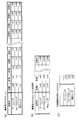
- the maximum speed (maximum speed limit) determined by the stepping motor characteristics and the load applied to the stepping motor is determined for each section. This maximum speed is stored in the memory in the control microcomputer 101.
- FIG. 13A shows the maximum speed limits La0 to La99 of the zoom lens, the maximum speed limits Lb0 to Lb99 of the focus lens, and the maximum speed limits Lc0 to Lc99 of the correction lens corresponding to each section of the section 0 to 99. It is remembered. As described above, the table showing the maximum speed limit is stored in the memory in the control microcomputer 101.
- FIG. 13B shows the maximum speed limit for low temperature.
- the maximum speed of a stepping motor also changes depending on the ambient temperature.
- the maximum speed limit Lat0 to Lat99 of the zoom lens, the maximum speed limit Lbt0 to Lbt99 of the focus lens, and the maximum speed limit Lct0 to Lct99 of the correction lens are shown.
- a temperature sensor may be provided in the camera to measure the temperature, and if the temperature is lower than the predetermined temperature, the table may be switched to the table shown in FIG. 13 (b) for reading.
- the table may be different depending on other parameters, not limited to the temperature.
- the focus lens 253 may have a table for each subject distance.
- FIG. 13C shows a unit pulse of the acceleration / deceleration stage.
- the speed control of the stepping motor is performed by using the acceleration / deceleration stage 1 and the acceleration / deceleration stage 2.
- the example shown in FIG. 13C is the unit pulses Las, Lbs, and Lcs in the acceleration / deceleration stage 1 and the acceleration / deceleration stage 2.
- the unit pulse is one pulse, and in the example shown in FIG. 10, the unit pulse is two pulses.
- FIG. 14 shows an example of the section time_table.
- the predetermined section time tt in each section 0 to 99 is stored as a table in the memory in the control microcomputer 101 according to the zoom speeds A to G.
- FIG. 14 shows only one table, other zoom speeds may be changed depending on the application, environment, etc. In that case, a plurality of tables are prepared. Further, a plurality of tables may be prepared depending on whether or not the silent mode is set, the temperature, and the like.
- FIG. 15 shows an example in which the “unit pulse of the acceleration / deceleration stage” is one pulse.
- FIG. 15 shows a case where the sixth pls in the section n is set to a lower speed (driving time per pulse) than the acceleration / deceleration stage 2, and accelerates from this state to the maximum speed in the section n + 1. .. It is assumed that the 7th pls, which is the first pls of the section n + 1, is set to the acceleration / deceleration stage 2, the 8th pls is set to the acceleration / deceleration stage 1, and the highest speed is set in the 9th pls and thereafter. In the graph shown in FIG. 15, the area of the shaded portion corresponds to the driving time of the section n + 1.
- the drive time in the acceleration / deceleration stage for driving the "unit pulse of the acceleration / deceleration stage" at the speeds of all the “acceleration / deceleration stages” is obtained.
- the number of pulses used in all the acceleration / deceleration stages is obtained, and the remaining “number of pulses" in the section n + 1 is obtained by subtracting the "total number of pulses used in all acceleration / deceleration stages" from the "number of pulses in the section”. Then, the drive time for a constant speed with the remaining "number of pulses" as the maximum speed is obtained.
- the sum of the drive time of the acceleration / deceleration stage and the drive time for a constant speed is the shortest time in the section n + 1.
- the calculation may be performed using the acceleration / deceleration stages corresponding to the straddles and the required number of pulses.
- FIG. 16 shows a control example corresponding to the calculation of the shortest time when the stop time when the stepping motor is stopped is included in step S31 of FIG. Accelerate once, reach the maximum speed, then decelerate and stop.
- the 18th pls of the section n + 2 it is the driving speed between the acceleration / deceleration stage 1 and the acceleration / deceleration stage 2, and in the 19th pls of the section n + 3, it accelerates to the acceleration / deceleration stage 1. At the 20th pls, it accelerates at the highest speed.
- the maximum speed is maintained from the 21st pls to the 23rd pls, the speed is reduced to the acceleration / deceleration stage 1 at the 24th pls, and the speed is reduced to the acceleration / deceleration stage 2 at the 25th pls to stop.
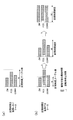
- the control microcomputer 101 determines whether or not the time required for driving each section does not exceed the section time for each section, and determines whether or not to extend the section time. For example, as shown in FIG. 12A, the driving time of the zoom lens (ZM) 250 and the driving time of the focus lens (FCS) 253 and the correction lens (CORR) 254 are stored in the section time_table. If the section time tt is not exceeded, the section time is not extended. That is, the section time tt is adopted as the final section time.
- the section time is extended.
- the drive time (minimum time) of the focus lens (FCS) 253 exceeds the section time tt stored in the section time_table.
- the section time tt is extended to the time required to drive the focus lens (FCS) 253 (shortest time), and the other lenses (zoom lens (ZM) 250 and correction lens (CORR) 254 are also extended. Control is performed according to the determined section time (fixed section time td).
- the fixed section time td shown in FIG. 12 (b) corresponds to the final section time in step S33 (see FIG. 11) by adding the stop time at the time of reversal and the direction reversal stop time t2c in FIG. ..
- FIGS. 17 (a) to 17 (c) are next to the seventh pls, which is the first pls in the section n + 1.
- the setting of the drive time of pls after the 8th pls is different.
- FIG. 17A shows a case where the speed setting parameter is determined without straddling the acceleration / deceleration stages.
- the 7th pls in the section n + 1 is set as the speed of the acceleration / deceleration stage 2, and thereafter, the speed of the acceleration / deceleration stage 2 is set from the 8th pls to the 12th pls. ..
- the speed setting parameters of the section n + 1 are (1) the number of pulses in the acceleration / deceleration period is 0, (2) the time in the acceleration / deceleration period is 0, (3) the number of pulses in the constant speed period is 6, and (4) constant.
- the time of the speed period is the fixed section time td (the fixed section time td-t2c when the inversion of the lens is included).
- FIG. 17B is an example in which the speed setting parameter is determined by straddling one acceleration / deceleration stage.
- the 7th pls in the section n + 1 is set to the speed of the acceleration / deceleration stage 2
- the 8th pls is set to the speed of the acceleration / deceleration stage 1.
- the acceleration / deceleration stage 1 is set from the 8th pls to the 12th pls.
- the speed on the side lower than the acceleration / deceleration stage 2 in the section n is set, the speed of the acceleration / deceleration stage 2 is set in the section n + 1, and the speed of the acceleration / deceleration stage 1 is set, and the acceleration / deceleration stage 2 is straddled. It straddles one (once) acceleration / deceleration stages.
- the speed setting parameters of the section n + 1 are (1) the number of pulses in the acceleration / deceleration period is 1, (2) the time in the acceleration / deceleration period is ta, (3) the number of pulses in the constant speed period is 5, and (4) constant.
- the time of the speed period is the fixed section time td-ta (the fixed section time td-t2c-ta when the inversion of the lens is included).
- the time ta of the acceleration / deceleration period is the drive time (speed) of the acceleration / deceleration stage 2 corresponding to the seventh pls, which is the first pls of the section n + 1 shown in FIG. 17 (b).
- FIG. 17C is an example in which the speed setting parameter is determined by straddling two acceleration / deceleration stages.
- the speed of the acceleration / deceleration stage 2 is set in the 7th pls of the section n + 1
- the speed of the acceleration / deceleration stage 1 is set in the 8th pls
- the maximum speed is set in the 9th pls. After that, the highest speed is set from the 9th pls to the 12th pls.
- the speed setting parameters of the section n + 1 are (1) the number of pulses in the acceleration / deceleration period is 2, (2) the time in the acceleration / deceleration period is ta, (3) the number of pulses in the constant speed period is 4, and (4) constant.
- the time of the speed period is the fixed section time td-ta (when the inversion of the lens is included, the fixed section time td-t2c-ta).
- the time ta of the acceleration / deceleration period corresponds to the drive time (speed) of the acceleration / deceleration stage 2 corresponding to the 7th pls, which is the first pls of the section n + 1 shown in FIG. 17 (c), and the 8th pls. It is the sum of the drive times (speeds) of the acceleration / deceleration stages 1.
- the section time of the section n + 1 in FIGS. 17 (a) to 17 (c) is the sum of the areas of the bar graphs in the section n + 1 (shown by the hatched portion). Assuming that the section times in the sections n + 1 of FIGS. 17 (a), (b), and (c) are time A, time B, and time C, respectively, the relationship of time A> time B> time C is clear from FIG. Holds. The shorter the time, the faster it can be driven. In determining the speed setting parameter of the section in step S35, the final section time (fixed section time td) calculated in step S33 and the times A to C are sequentially compared.
- the “fixed section time td” is sequentially compared with the “time A + t2c”, “time B + t2c”, and “time C + t2c”. It is possible to control within the "final section time” under the condition that the time A to the time C is the same as or shorter than the final section time. The control is determined so that it can be controlled and the number of acceleration / deceleration stages used is the smallest. For example, if the relationship is time A> time B> "last section time"> time C, time C corresponds. As shown in FIG.
- the time C corresponds to the relationship of time A + t2c> time B + t2c> "final section time”> time C + t2c.
- the time is C
- two acceleration / deceleration stages are used.
- the speed after that is set to a constant speed (Pls numbers 9 to 12 in the case of FIG. 17 (c)).
- the "number of acceleration / deceleration stages used in the section” is determined in this way, the “number of pulses of the acceleration / deceleration stage” and the “time of the acceleration / deceleration period” are selected from the “unit pulse of the acceleration / deceleration stage (see FIG. 13C)". Calculate the "number of pulses during a constant speed period”.
- the "time of a constant speed period" is calculated.
- the time during acceleration / deceleration is subtracted from the time of the section, and the stop time t2c for the direction reversal stop shown in FIG. 8 is further subtracted.
- tc the time of the constant speed period
- td the section time (fixed section time)
- ta the time of the acceleration / deceleration period
- R is the stop time for direction reversal. It can be calculated by the following formula (1).
- tk td-ta-R ... (1)
- step S37 the calculation of the speed division in the constant speed period in step S37 will be described using the flowchart shown in FIG.
- step S53 if the number of pulses in the constant speed period is 0, it is set in case 1 (S55). Further, as a result of the determination in step S53, when the number of pulses in the constant speed period is 1, it is set in case 2 (S57). Further, when the number of pulses in the constant speed period is 2 or more, it is set in case 3 (S59).
- a constant speed period speed division calculation is performed (S61).
- the two drive times (integer multiples of the control unit time) closest to the constant speed calculated in step S35 are selected, the number of pulses to be driven in each drive time is calculated, and the error is minimized.
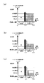
- the speed division for a constant speed period will be described with reference to FIG. FIG. 19 shows only the constant speed period, and the acceleration / deceleration period is omitted.
- the horizontal axis represents applied pulses pls.
- the vertical axis indicates the drive time for each pulse, and the longer the drive time for each pulse, the lower the drive speed.
- the drive time of one pulse can be controlled only in the control resolution Tres unit (control unit time).
- the average time Tave is a value obtained by dividing the number of pulses Tn in the constant speed period by the time in the constant speed period, and may not be realized due to the limitation of the control resolution (control unit time).
- the number of pulses Tn in the constant speed period is determined in step S35 (3), and the time in the constant speed period is determined in step S35 (4).
- the drive time can be set according to the control unit time for each drive pulse of the stepping motor.
- the first time Tfast_t and the second time Tslow_t are controllable one-pulse drive times closest to the average time Tave.
- the time in the constant speed period is the sum of the areas of each bar graph in FIG.
- the number of pulses Tn is distributed (divided) to the optimum number of pulses for the first time Tfast_t and the second time Tslow_t, so that the total constant speed period time in that case is all pulses.
- the driving time of is set to be substantially equal to the time of the constant speed period when the virtual average time Tave is used.
- step S61 the following parameters (a) to (d) are obtained.
- step S59 when case 3 is set and the number of pulses Tn of the constant speed period Tc is 2, the “drive time for each pulse” calculated by time ⁇ number of pulses (rounded down to the nearest whole number). And, two kinds of speeds of "driving time for each pulse” which are longer by the control unit time are obtained, and Tc is distributed for a constant speed period.
- Tslow_t Tfast_t + Tres ⁇ ⁇ ⁇ (4)
- Tn_slow (Tc-Tn ⁇ Tfast_t) ⁇ Tres ⁇ ⁇ ⁇ (5)
- the pulse number Tn_fast of the period Fast within the constant speed period is then calculated from the following (6).
- Tn_fast Tn-Tn_slow ... (6)
- the above parameters (a) to (d) can be obtained from the above equations (3) to (6).
- FIG. 20 shows a case where the speed is not divided during a constant speed period.
- FIG. 20 includes both a constant speed period and an acceleration / deceleration period.
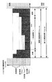
- the actual control value Trea which is the closest to the calculated value of the drive time for each pulse in the constant speed period Tc (corresponding to the combined time Tave in FIG. 19) in terms of control resolution (control unit time) is the constant speed period Tc. All pulses are driven.
- the difference between the calculated value Tave and the actual control value Trea within the constant speed period Tc is the total error regarding the time of the constant speed period Tc.
- the target drive time Tmov_tar is controlled by the actual drive time Tmov_rea in the constant speed period Tc, the time to reach the next zoom position position Zp will be shortened by the error, and other lenses will be predetermined.
- the time (waiting time) to wait until the position is reached increases. Alternatively, at the next zoom position, the lens is considered to have stopped and recalculation will occur.
- FIG. 21 shows a case where the constant speed period speed is not divided, and is shown in comparison with the case where the constant speed period speed is divided in FIG. Similar to FIG. 19, FIG. 21 shows only the constant speed period and omits the acceleration / deceleration period.
- the value obtained by multiplying the difference between the average time Tave and the actual time Trea by the number of pulses results in a time error of the constant speed period Tc.
- the constant speed period Tc is divided into a first period Fast and a second period Slow, and different drive times (1st time Tfast_t, 2nd time Tslow_t) are assigned to each of them.
- time is the sum of the areas of the bar graph. That is, the time error that occurs within a fixed speed period can be suppressed to the control resolution (control unit time) or less by distributing the two controllable speeds and the number of pulses.
- FIG. 22 shows a case where the speed is divided for a constant speed period. Similar to FIG. 20, a constant speed period and an acceleration / deceleration period are included. Compared with the case of FIG. 20, in the constant speed period Tc, the drive time for each pulse is divided into a period Fast and a period Slow of two speeds of the first time Tfast_t and the second time Tslow_t. Therefore, in the constant speed period Tc, the actual drive time Tmov_rea is closer to the target drive time Tmov_tar than in the case of FIG. 20. As a result, the difference between the two drive times, that is, the total error is reduced as compared with the case of FIG.
- each lens can reach a predetermined position substantially at the same time. If the zoom position Zp is set densely between the telephoto end and the wide-angle end, the accuracy of each lens position while the lens is being driven is improved, and the image quality of the live view image and / or the moving image image can be further improved.
- the drive time of a plurality of consecutive pulses is set as the first time
- the drive time of the plurality of consecutive pulses is set as the second time.
- the drive time of the first pulse is the first time
- the drive time of the next one pulse is the second time
- the next two pulses are the first time and the second time, respectively. It is said.
- the first time of one pulse and the second time of two pulses are alternately repeated three times. In this way, the zoom lens 250, the focus lens 253, and the correction lens 254 are each brought close to the calculated speed by combining the speeds of the constant speed period by changing the order of the pulses of the two drive times.
- the modified example is not limited to the example shown in FIG. 23, and for example, the drive time of a plurality of consecutive pulses is set as the second time, and then the drive time of the plurality of consecutive pulses is set as the first time. May be good. Further, not limited to the example shown in FIG. 23, two pulses may be alternately driven, and three or more pulses may be alternately driven.
- the interval between the zoom positions where the positions of the plurality of lenses are aligned is set as the "section", and the "section” is set as the "predetermined time”. Controls the moving speed of multiple lenses.
- the time to move the predetermined "section” is set as the "predetermined time”
- the shortest time that can be controlled by the "section” is calculated for each lens (see S31 in FIG. 11), and the shortest time is the "predetermined time”. If there is a lens that exceeds the above, the "predetermined time” is extended (see S33 in FIG. 11 and FIG. 12 (b)).
- the shortest time of the lens that exceeds this is defined as a "predetermined time”.
- the first stepping motor and the second stepping motor are used. It has a period for driving at least one of the stepping motors at a constant speed (see, for example, the constant speed period Tc in FIG. 22).
- Tc constant speed period
- the time required for the zoom lens and the focus lens to move in a predetermined section with a predetermined number of pulses as a predetermined time see, for example, the fixed section time td in FIG.
- the drive time is the average drive time obtained by dividing the drive time by the number of pulses in that period (see, for example, the average time Tave in FIG. 21B)
- the period for driving at a constant speed is divided into a plurality of periods and averaged.
- a plurality of drive times sandwiching the drive time are set as drive pulses for a plurality of periods (see, for example, S37 in FIG. 11, S61 in FIG. 18, and drive time for each pulse in the constant speed period Tc in FIG. 22). Therefore, the accuracy of the lens position can be ensured while the lens is being driven, and the appearance of the live view image and / or the moving image can be improved.
- the stepping motor having the correction lens 254 and driving the correction lens 254 is also constant, like the stepping motor for driving the zoom lens 250 and the focus lens 253.
- this period was divided into a plurality of engines, and a plurality of drive times with an average drive time in between were set for drive pulses of a plurality of engines.
- the present invention is not limited to this, and in the case of a photographing lens that does not include the correction lens 254, this drive control may not be performed, and even if the correction lens 254 is included, this drive control may be omitted.
- the chips such as the image sensor drive IC 110, the image processing IC 102, the motor driver 120, and the SDRAM 103 are separate chips from the control microcomputer 101, but some of them are the same.
- the chip may be shared, or it may be divided into different chips.
- the hardware circuit instead of the hardware circuit provided on the above-mentioned chip, it may be configured in software by a CPU and a program, and a gate circuit or the like generated based on a program language described by Verilog may be used. It may be configured by hardware, or it may be configured by using DSP (Digital Signal Processor). Of course, these may be combined as appropriate.
- DSP Digital Signal Processor
- each part may be a processor each configured as an electronic circuit, or may be each circuit part in a processor composed of an integrated circuit such as an FPGA (Field Programmable Gate Array).
- a processor composed of one or more CPUs may execute the functions of each unit by reading and executing the computer program recorded on the recording medium.
- a digital camera has been described as a device for shooting, but the camera may be a digital single-lens reflex camera, a mirrorless camera, or a compact digital camera, such as a video camera or a movie camera. It may be a camera for various moving images, and further, a camera built in a mobile phone, a smartphone, a mobile information terminal, a personal computer (PC), a tablet computer, a game device, etc., a medical camera (for example, a medical endoscope). , Cameras for scientific instruments such as microscopes, industrial endoscopes, automobile-mounted cameras, surveillance cameras may be used. In any case, the present invention can be applied to any device having a photographing lens capable of varying the focal length.
- the controls mainly described in the flowchart can often be set by a program, and may be stored in a recording medium or a recording unit.
- the recording method to the recording medium and the recording unit may be recorded at the time of product shipment, the distributed recording medium may be used, or may be downloaded via the Internet.
- the operation in the present embodiment has been described using a flowchart, but the order of the processing procedures may be changed, or any step may be omitted. Steps may be added, and specific processing contents in each step may be changed.
- the present invention is not limited to the above embodiment as it is, and at the implementation stage, the components can be modified and embodied without departing from the gist thereof.
- various inventions can be formed by an appropriate combination of the plurality of components disclosed in the above-described embodiment. For example, some components of all the components shown in the embodiment may be deleted. In addition, components across different embodiments may be combined as appropriate.
Landscapes
- Physics & Mathematics (AREA)
- General Physics & Mathematics (AREA)
- Engineering & Computer Science (AREA)
- Power Engineering (AREA)
- Optics & Photonics (AREA)
- Lens Barrels (AREA)
- Studio Devices (AREA)
- Automatic Focus Adjustment (AREA)
Priority Applications (3)
| Application Number | Priority Date | Filing Date | Title |
|---|---|---|---|
| JP2021536449A JP7159478B2 (ja) | 2019-07-26 | 2019-07-26 | レンズ制御装置およびレンズ制御方法 |
| PCT/JP2019/029417 WO2021019600A1 (ja) | 2019-07-26 | 2019-07-26 | レンズ制御装置およびレンズ制御方法 |
| US17/579,533 US11906894B2 (en) | 2019-07-26 | 2022-01-19 | Lens control device and lens control method |
Applications Claiming Priority (1)
| Application Number | Priority Date | Filing Date | Title |
|---|---|---|---|
| PCT/JP2019/029417 WO2021019600A1 (ja) | 2019-07-26 | 2019-07-26 | レンズ制御装置およびレンズ制御方法 |
Related Child Applications (1)
| Application Number | Title | Priority Date | Filing Date |
|---|---|---|---|
| US17/579,533 Continuation US11906894B2 (en) | 2019-07-26 | 2022-01-19 | Lens control device and lens control method |
Publications (1)
| Publication Number | Publication Date |
|---|---|
| WO2021019600A1 true WO2021019600A1 (ja) | 2021-02-04 |
Family
ID=74228366
Family Applications (1)
| Application Number | Title | Priority Date | Filing Date |
|---|---|---|---|
| PCT/JP2019/029417 Ceased WO2021019600A1 (ja) | 2019-07-26 | 2019-07-26 | レンズ制御装置およびレンズ制御方法 |
Country Status (3)
| Country | Link |
|---|---|
| US (1) | US11906894B2 (https=) |
| JP (1) | JP7159478B2 (https=) |
| WO (1) | WO2021019600A1 (https=) |
Families Citing this family (2)
| Publication number | Priority date | Publication date | Assignee | Title |
|---|---|---|---|---|
| JP7749490B2 (ja) * | 2022-02-18 | 2025-10-06 | キヤノン株式会社 | 撮像レンズ装置および撮像装置 |
| JP2025035541A (ja) * | 2023-09-04 | 2025-03-14 | キヤノン株式会社 | 制御装置、レンズ装置、撮像装置、制御方法、およびプログラム |
Citations (2)
| Publication number | Priority date | Publication date | Assignee | Title |
|---|---|---|---|---|
| JPH10164417A (ja) * | 1996-12-03 | 1998-06-19 | Canon Inc | 撮像装置、その制御方法、記憶媒体、及びレンズ制御装置 |
| JP2008191479A (ja) * | 2007-02-06 | 2008-08-21 | Nikon Corp | 光学系駆動装置およびカメラ |
Family Cites Families (3)
| Publication number | Priority date | Publication date | Assignee | Title |
|---|---|---|---|---|
| US6577343B2 (en) | 1996-12-03 | 2003-06-10 | Canon Kabushiki Kaisha | Image pickup apparatus with lens control apparatus and focusing lens control |
| JP5471120B2 (ja) | 2009-02-13 | 2014-04-16 | 株式会社リコー | 撮影レンズ駆動制御装置および撮像装置 |
| JP5393769B2 (ja) * | 2011-12-27 | 2014-01-22 | オリンパスイメージング株式会社 | 光学機器および撮像装置 |
-
2019
- 2019-07-26 JP JP2021536449A patent/JP7159478B2/ja active Active
- 2019-07-26 WO PCT/JP2019/029417 patent/WO2021019600A1/ja not_active Ceased
-
2022
- 2022-01-19 US US17/579,533 patent/US11906894B2/en active Active
Patent Citations (2)
| Publication number | Priority date | Publication date | Assignee | Title |
|---|---|---|---|---|
| JPH10164417A (ja) * | 1996-12-03 | 1998-06-19 | Canon Inc | 撮像装置、その制御方法、記憶媒体、及びレンズ制御装置 |
| JP2008191479A (ja) * | 2007-02-06 | 2008-08-21 | Nikon Corp | 光学系駆動装置およびカメラ |
Also Published As
| Publication number | Publication date |
|---|---|
| JP7159478B2 (ja) | 2022-10-24 |
| JPWO2021019600A1 (https=) | 2021-02-04 |
| US11906894B2 (en) | 2024-02-20 |
| US20220137487A1 (en) | 2022-05-05 |
Similar Documents
| Publication | Publication Date | Title |
|---|---|---|
| US7113318B2 (en) | Light amount control apparatus, photographing apparatus, and filter | |
| US7884862B2 (en) | Camera and camera zoom control method | |
| JP5967544B2 (ja) | レンズ鏡筒、撮像装置およびカメラ | |
| US20110122268A1 (en) | Imaging device | |
| US9658428B2 (en) | Optical instrument and control method for lens | |
| WO2008044772A1 (fr) | Dispositif de prise d'images | |
| JP5178186B2 (ja) | レンズ位置制御装置、およびその制御方法 | |
| US11906894B2 (en) | Lens control device and lens control method | |
| JP5984489B2 (ja) | レンズ装置及びそれを有する撮像装置 | |
| US7589768B2 (en) | Image-taking apparatus and focus control method of image-taking apparatus with first and second control method in first zoom state and only second control method in second zoom state | |
| US8488226B2 (en) | Optical apparatus | |
| JP4848618B2 (ja) | 電子カメラ装置、及びフォーカス情報補正方法 | |
| JP7475872B2 (ja) | レンズ装置及びそれを有する撮像装置 | |
| JP2006243372A (ja) | カメラ | |
| JP2019091082A (ja) | 撮像装置 | |
| JP2011029719A5 (https=) | ||
| JP2017219697A (ja) | 撮像装置及び撮像装置の制御方法 | |
| US20250076738A1 (en) | Control apparatus, lens apparatus, image pickup apparatus, control method, and storage medium | |
| US12401902B2 (en) | Control apparatus, image pickup apparatus, control method, and storage medium | |
| JP4532929B2 (ja) | 撮像装置、その制御方法、制御プログラム及び記憶媒体 | |
| US20230280565A1 (en) | Control apparatus, lens apparatus, optical apparatus, and storage medium | |
| WO2024247890A1 (ja) | 撮像装置、制御方法、プログラム | |
| JP2024141577A (ja) | 絞り駆動制御装置、絞り駆動制御装置の作動方法、絞り駆動制御装置の作動プログラム、並びに撮像装置 | |
| JP2014095852A (ja) | 光学機器 | |
| JP2014155042A (ja) | 撮像装置 |
Legal Events
| Date | Code | Title | Description |
|---|---|---|---|
| 121 | Ep: the epo has been informed by wipo that ep was designated in this application |
Ref document number: 19939071 Country of ref document: EP Kind code of ref document: A1 |
|
| ENP | Entry into the national phase |
Ref document number: 2021536449 Country of ref document: JP Kind code of ref document: A |
|
| NENP | Non-entry into the national phase |
Ref country code: DE |
|
| 122 | Ep: pct application non-entry in european phase |
Ref document number: 19939071 Country of ref document: EP Kind code of ref document: A1 |