WO2021006052A1 - 配線モジュール、蓄電モジュール、バスバー、および蓄電モジュールの製造方法 - Google Patents
配線モジュール、蓄電モジュール、バスバー、および蓄電モジュールの製造方法 Download PDFInfo
- Publication number
- WO2021006052A1 WO2021006052A1 PCT/JP2020/024996 JP2020024996W WO2021006052A1 WO 2021006052 A1 WO2021006052 A1 WO 2021006052A1 JP 2020024996 W JP2020024996 W JP 2020024996W WO 2021006052 A1 WO2021006052 A1 WO 2021006052A1
- Authority
- WO
- WIPO (PCT)
- Prior art keywords
- bus bar
- power storage
- electric wire
- main body
- terminal
- Prior art date
- Legal status (The legal status is an assumption and is not a legal conclusion. Google has not performed a legal analysis and makes no representation as to the accuracy of the status listed.)
- Ceased
Links
Images





Classifications
-
- H—ELECTRICITY
- H01—ELECTRIC ELEMENTS
- H01M—PROCESSES OR MEANS, e.g. BATTERIES, FOR THE DIRECT CONVERSION OF CHEMICAL ENERGY INTO ELECTRICAL ENERGY
- H01M50/00—Constructional details or processes of manufacture of the non-active parts of electrochemical cells other than fuel cells, e.g. hybrid cells
- H01M50/20—Mountings; Secondary casings or frames; Racks, modules or packs; Suspension devices; Shock absorbers; Transport or carrying devices; Holders
- H01M50/298—Mountings; Secondary casings or frames; Racks, modules or packs; Suspension devices; Shock absorbers; Transport or carrying devices; Holders characterised by the wiring of battery packs
-
- H—ELECTRICITY
- H01—ELECTRIC ELEMENTS
- H01G—CAPACITORS; CAPACITORS, RECTIFIERS, DETECTORS, SWITCHING DEVICES, LIGHT-SENSITIVE OR TEMPERATURE-SENSITIVE DEVICES OF THE ELECTROLYTIC TYPE
- H01G11/00—Hybrid capacitors, i.e. capacitors having different positive and negative electrodes; Electric double-layer [EDL] capacitors; Processes for the manufacture thereof or of parts thereof
- H01G11/10—Multiple hybrid or EDL capacitors, e.g. arrays or modules
- H01G11/12—Stacked hybrid or EDL capacitors
-
- H—ELECTRICITY
- H01—ELECTRIC ELEMENTS
- H01G—CAPACITORS; CAPACITORS, RECTIFIERS, DETECTORS, SWITCHING DEVICES, LIGHT-SENSITIVE OR TEMPERATURE-SENSITIVE DEVICES OF THE ELECTROLYTIC TYPE
- H01G11/00—Hybrid capacitors, i.e. capacitors having different positive and negative electrodes; Electric double-layer [EDL] capacitors; Processes for the manufacture thereof or of parts thereof
- H01G11/74—Terminals, e.g. extensions of current collectors
- H01G11/76—Terminals, e.g. extensions of current collectors specially adapted for integration in multiple or stacked hybrid or EDL capacitors
-
- H—ELECTRICITY
- H01—ELECTRIC ELEMENTS
- H01G—CAPACITORS; CAPACITORS, RECTIFIERS, DETECTORS, SWITCHING DEVICES, LIGHT-SENSITIVE OR TEMPERATURE-SENSITIVE DEVICES OF THE ELECTROLYTIC TYPE
- H01G11/00—Hybrid capacitors, i.e. capacitors having different positive and negative electrodes; Electric double-layer [EDL] capacitors; Processes for the manufacture thereof or of parts thereof
- H01G11/84—Processes for the manufacture of hybrid or EDL capacitors, or components thereof
-
- H—ELECTRICITY
- H01—ELECTRIC ELEMENTS
- H01M—PROCESSES OR MEANS, e.g. BATTERIES, FOR THE DIRECT CONVERSION OF CHEMICAL ENERGY INTO ELECTRICAL ENERGY
- H01M10/00—Secondary cells; Manufacture thereof
- H01M10/42—Methods or arrangements for servicing or maintenance of secondary cells or secondary half-cells
- H01M10/48—Accumulators combined with arrangements for measuring, testing or indicating the condition of cells, e.g. the level or density of the electrolyte
- H01M10/482—Accumulators combined with arrangements for measuring, testing or indicating the condition of cells, e.g. the level or density of the electrolyte for several batteries or cells simultaneously or sequentially
-
- H—ELECTRICITY
- H01—ELECTRIC ELEMENTS
- H01M—PROCESSES OR MEANS, e.g. BATTERIES, FOR THE DIRECT CONVERSION OF CHEMICAL ENERGY INTO ELECTRICAL ENERGY
- H01M50/00—Constructional details or processes of manufacture of the non-active parts of electrochemical cells other than fuel cells, e.g. hybrid cells
- H01M50/20—Mountings; Secondary casings or frames; Racks, modules or packs; Suspension devices; Shock absorbers; Transport or carrying devices; Holders
- H01M50/204—Racks, modules or packs for multiple batteries or multiple cells
- H01M50/207—Racks, modules or packs for multiple batteries or multiple cells characterised by their shape
- H01M50/209—Racks, modules or packs for multiple batteries or multiple cells characterised by their shape adapted for prismatic or rectangular cells
-
- H—ELECTRICITY
- H01—ELECTRIC ELEMENTS
- H01M—PROCESSES OR MEANS, e.g. BATTERIES, FOR THE DIRECT CONVERSION OF CHEMICAL ENERGY INTO ELECTRICAL ENERGY
- H01M50/00—Constructional details or processes of manufacture of the non-active parts of electrochemical cells other than fuel cells, e.g. hybrid cells
- H01M50/20—Mountings; Secondary casings or frames; Racks, modules or packs; Suspension devices; Shock absorbers; Transport or carrying devices; Holders
- H01M50/249—Mountings; Secondary casings or frames; Racks, modules or packs; Suspension devices; Shock absorbers; Transport or carrying devices; Holders specially adapted for aircraft or vehicles, e.g. cars or trains
-
- H—ELECTRICITY
- H01—ELECTRIC ELEMENTS
- H01M—PROCESSES OR MEANS, e.g. BATTERIES, FOR THE DIRECT CONVERSION OF CHEMICAL ENERGY INTO ELECTRICAL ENERGY
- H01M50/00—Constructional details or processes of manufacture of the non-active parts of electrochemical cells other than fuel cells, e.g. hybrid cells
- H01M50/20—Mountings; Secondary casings or frames; Racks, modules or packs; Suspension devices; Shock absorbers; Transport or carrying devices; Holders
- H01M50/296—Mountings; Secondary casings or frames; Racks, modules or packs; Suspension devices; Shock absorbers; Transport or carrying devices; Holders characterised by terminals of battery packs
-
- H—ELECTRICITY
- H01—ELECTRIC ELEMENTS
- H01M—PROCESSES OR MEANS, e.g. BATTERIES, FOR THE DIRECT CONVERSION OF CHEMICAL ENERGY INTO ELECTRICAL ENERGY
- H01M50/00—Constructional details or processes of manufacture of the non-active parts of electrochemical cells other than fuel cells, e.g. hybrid cells
- H01M50/50—Current conducting connections for cells or batteries
-
- H—ELECTRICITY
- H01—ELECTRIC ELEMENTS
- H01M—PROCESSES OR MEANS, e.g. BATTERIES, FOR THE DIRECT CONVERSION OF CHEMICAL ENERGY INTO ELECTRICAL ENERGY
- H01M50/00—Constructional details or processes of manufacture of the non-active parts of electrochemical cells other than fuel cells, e.g. hybrid cells
- H01M50/50—Current conducting connections for cells or batteries
- H01M50/502—Interconnectors for connecting terminals of adjacent batteries; Interconnectors for connecting cells outside a battery casing
- H01M50/503—Interconnectors for connecting terminals of adjacent batteries; Interconnectors for connecting cells outside a battery casing characterised by the shape of the interconnectors
-
- H—ELECTRICITY
- H01—ELECTRIC ELEMENTS
- H01M—PROCESSES OR MEANS, e.g. BATTERIES, FOR THE DIRECT CONVERSION OF CHEMICAL ENERGY INTO ELECTRICAL ENERGY
- H01M50/00—Constructional details or processes of manufacture of the non-active parts of electrochemical cells other than fuel cells, e.g. hybrid cells
- H01M50/50—Current conducting connections for cells or batteries
- H01M50/502—Interconnectors for connecting terminals of adjacent batteries; Interconnectors for connecting cells outside a battery casing
- H01M50/505—Interconnectors for connecting terminals of adjacent batteries; Interconnectors for connecting cells outside a battery casing comprising a single busbar
-
- H—ELECTRICITY
- H01—ELECTRIC ELEMENTS
- H01M—PROCESSES OR MEANS, e.g. BATTERIES, FOR THE DIRECT CONVERSION OF CHEMICAL ENERGY INTO ELECTRICAL ENERGY
- H01M50/00—Constructional details or processes of manufacture of the non-active parts of electrochemical cells other than fuel cells, e.g. hybrid cells
- H01M50/50—Current conducting connections for cells or batteries
- H01M50/502—Interconnectors for connecting terminals of adjacent batteries; Interconnectors for connecting cells outside a battery casing
- H01M50/507—Interconnectors for connecting terminals of adjacent batteries; Interconnectors for connecting cells outside a battery casing comprising an arrangement of two or more busbars within a container structure, e.g. busbar modules
-
- H—ELECTRICITY
- H01—ELECTRIC ELEMENTS
- H01M—PROCESSES OR MEANS, e.g. BATTERIES, FOR THE DIRECT CONVERSION OF CHEMICAL ENERGY INTO ELECTRICAL ENERGY
- H01M50/00—Constructional details or processes of manufacture of the non-active parts of electrochemical cells other than fuel cells, e.g. hybrid cells
- H01M50/50—Current conducting connections for cells or batteries
- H01M50/502—Interconnectors for connecting terminals of adjacent batteries; Interconnectors for connecting cells outside a battery casing
- H01M50/514—Methods for interconnecting adjacent batteries or cells
- H01M50/516—Methods for interconnecting adjacent batteries or cells by welding, soldering or brazing
-
- H—ELECTRICITY
- H01—ELECTRIC ELEMENTS
- H01M—PROCESSES OR MEANS, e.g. BATTERIES, FOR THE DIRECT CONVERSION OF CHEMICAL ENERGY INTO ELECTRICAL ENERGY
- H01M50/00—Constructional details or processes of manufacture of the non-active parts of electrochemical cells other than fuel cells, e.g. hybrid cells
- H01M50/50—Current conducting connections for cells or batteries
- H01M50/502—Interconnectors for connecting terminals of adjacent batteries; Interconnectors for connecting cells outside a battery casing
- H01M50/521—Interconnectors for connecting terminals of adjacent batteries; Interconnectors for connecting cells outside a battery casing characterised by the material
- H01M50/522—Inorganic material
-
- H—ELECTRICITY
- H01—ELECTRIC ELEMENTS
- H01M—PROCESSES OR MEANS, e.g. BATTERIES, FOR THE DIRECT CONVERSION OF CHEMICAL ENERGY INTO ELECTRICAL ENERGY
- H01M50/00—Constructional details or processes of manufacture of the non-active parts of electrochemical cells other than fuel cells, e.g. hybrid cells
- H01M50/50—Current conducting connections for cells or batteries
- H01M50/543—Terminals
- H01M50/547—Terminals characterised by the disposition of the terminals on the cells
- H01M50/55—Terminals characterised by the disposition of the terminals on the cells on the same side of the cell
-
- H—ELECTRICITY
- H01—ELECTRIC ELEMENTS
- H01M—PROCESSES OR MEANS, e.g. BATTERIES, FOR THE DIRECT CONVERSION OF CHEMICAL ENERGY INTO ELECTRICAL ENERGY
- H01M50/00—Constructional details or processes of manufacture of the non-active parts of electrochemical cells other than fuel cells, e.g. hybrid cells
- H01M50/50—Current conducting connections for cells or batteries
- H01M50/543—Terminals
- H01M50/552—Terminals characterised by their shape
- H01M50/553—Terminals adapted for prismatic, pouch or rectangular cells
-
- H—ELECTRICITY
- H01—ELECTRIC ELEMENTS
- H01M—PROCESSES OR MEANS, e.g. BATTERIES, FOR THE DIRECT CONVERSION OF CHEMICAL ENERGY INTO ELECTRICAL ENERGY
- H01M50/00—Constructional details or processes of manufacture of the non-active parts of electrochemical cells other than fuel cells, e.g. hybrid cells
- H01M50/50—Current conducting connections for cells or batteries
- H01M50/569—Constructional details of current conducting connections for detecting conditions inside cells or batteries, e.g. details of voltage sensing terminals
-
- H—ELECTRICITY
- H01—ELECTRIC ELEMENTS
- H01M—PROCESSES OR MEANS, e.g. BATTERIES, FOR THE DIRECT CONVERSION OF CHEMICAL ENERGY INTO ELECTRICAL ENERGY
- H01M2220/00—Batteries for particular applications
- H01M2220/20—Batteries in motive systems, e.g. vehicle, ship, plane
-
- Y—GENERAL TAGGING OF NEW TECHNOLOGICAL DEVELOPMENTS; GENERAL TAGGING OF CROSS-SECTIONAL TECHNOLOGIES SPANNING OVER SEVERAL SECTIONS OF THE IPC; TECHNICAL SUBJECTS COVERED BY FORMER USPC CROSS-REFERENCE ART COLLECTIONS [XRACs] AND DIGESTS
- Y02—TECHNOLOGIES OR APPLICATIONS FOR MITIGATION OR ADAPTATION AGAINST CLIMATE CHANGE
- Y02E—REDUCTION OF GREENHOUSE GAS [GHG] EMISSIONS, RELATED TO ENERGY GENERATION, TRANSMISSION OR DISTRIBUTION
- Y02E60/00—Enabling technologies; Technologies with a potential or indirect contribution to GHG emissions mitigation
- Y02E60/10—Energy storage using batteries
Definitions
- This disclosure relates to a wiring module, a power storage module, a bus bar, and a method for manufacturing a power storage module.
- a battery module described in Patent Document 1 Japanese Unexamined Patent Publication No. 11-120986
- a battery module in which a battery wiring module is attached to a cell group in which a plurality of cell cells provided with electrode terminals are arranged.
- This type of battery module is attached to a vehicle such as an electric vehicle or a hybrid vehicle and used as a drive source for the vehicle.
- the above battery wiring module is provided with a plurality of bus bars for connecting electrode terminals and a resin protector for holding the bus bars.
- the present disclosure has been completed based on the above circumstances, and an object of the present disclosure is to provide a technique for a wiring module in which a manufacturing cost is reduced.
- the present disclosure is a wiring module that has electrode terminals and is attached to a plurality of power storage elements arranged along the arrangement direction, and is arranged on an insulating sheet and a surface of the sheet along the arrangement direction.
- the plurality of electric wires are provided, and the plurality of electric wires are electrically connected to a bus bar connected to the electrode terminals of the plurality of power storage elements.
- the manufacturing cost of the wiring module can be reduced.
- FIG. 1 is a schematic view showing a vehicle equipped with the power storage module according to the first embodiment.
- FIG. 2 is a partially enlarged plan view showing the power storage module according to the first embodiment.
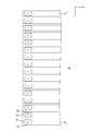
- FIG. 3 is a partially enlarged plan view showing a group of power storage elements.
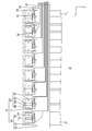
- FIG. 4 is a plan view showing the wiring module.
- FIG. 5 is a cross-sectional view showing a fixed structure of the electric wire and the sheet.
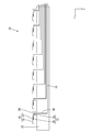
- FIG. 6 is a perspective view showing a bus bar.
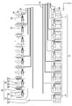
- FIG. 7 is a partially enlarged plan view showing a state in which the bus bar is connected to the electrode terminal of the power storage element.
- FIG. 8 is a cross-sectional view showing a bus bar.
- FIG. 1 is a schematic view showing a vehicle equipped with the power storage module according to the first embodiment.
- FIG. 2 is a partially enlarged plan view showing the power storage module according to the first embodiment.
- FIG. 3 is a partially enlarged plan view showing a group of power storage elements.
- FIG. 9 is a cross-sectional view showing a state in which the deformed portion of the bus bar is expanded in the front-rear direction.
- FIG. 10 is a partially enlarged plan view showing a connection structure between the protruding piece of the bus bar and the bus bar connecting portion of the terminal.
- FIG. 11 is a partially enlarged plan view showing a connection structure between the protruding piece of the bus bar and the bus bar connecting portion of the terminal.
- FIG. 12 is a plan view showing the power storage module according to the second embodiment.
- FIG. 13 is a partially enlarged plan view showing the power storage module according to the third embodiment.
- FIG. 14 is a partially enlarged plan view showing the power storage module according to the fourth embodiment.
- FIG. 15 is a plan view showing the bus bar according to the fifth embodiment.
- FIG. 16 is a partially enlarged plan view showing the power storage module according to the sixth embodiment.
- FIG. 17 is a partially enlarged flat circle diagram showing the power storage module according to the seventh embodiment.
- the present disclosure is a wiring module that has electrode terminals and is attached to a plurality of power storage elements arranged along the arrangement direction, and is attached to a sheet having an insulating property and a surface of the sheet in the arrangement direction.
- a plurality of electric wires arranged along the line are provided, and the plurality of electric wires are electrically connected to a bus bar connected to the electrode terminals of the plurality of power storage elements.
- the wiring module can be made low in height.
- the plurality of electric wires have a trunk line portion extending along the alignment direction and a branch line portion extending from the trunk line portion in an intersecting direction intersecting the alignment direction, and an end portion of the branch line portion is said. It is preferably electrically connected to the bus bar.
- a terminal is connected to the electric wire, and the terminal may be connected to the bus bar.
- the electric wire and the bus bar can be easily and electrically connected.
- the terminal has a bus bar connecting portion that extends in the alignment direction and connects to the bus bar.
- bus bar connection portion is formed so as to extend in the alignment direction, it is possible to follow the tolerance of the power storage element in the alignment direction within the range of the length dimension of the bus bar connection portion in the alignment direction.
- the terminal has an electric wire connecting portion extending in the intersecting direction and connecting to the core wire.
- the bus bar connection part By connecting the electric wire and the electric wire connection part of the terminal, the bus bar connection part can be arranged in a posture extending in the line-up direction. Thereby, the position accuracy of the terminal can be easily improved.
- the sheet has a base material and a welding layer, and the plurality of electric wires are fixed to the welding layer.
- the wiring module may be a wiring module for a vehicle that is mounted on a vehicle and used.
- the wiring module according to any one of (1) to (7) above, a plurality of power storage elements having electrode terminals and arranged along the arrangement direction, and the electrode terminals.
- a power storage module including a plurality of bus bars connected to the above, wherein the plurality of bus bars include a main body portion connected to the electrode terminal, and a protruding piece protruding from the main body portion and extending in the alignment direction. The projecting piece and the electric wire are electrically connected to each other.
- bus bar and the core wire of the electric wire can be electrically connected within the range of the length dimension in the alignment direction of the protruding pieces extending in the alignment direction, it is possible to follow the tolerance of the power storage element in the alignment direction.
- a terminal is connected to the end of the core wire, and the terminal has a bus bar connecting portion extending in the alignment direction and connecting to the bus bar, and the protruding piece and the bus bar connecting portion are connected to each other. It may have been.
- the main body and the bus bar are made of the same type of metal, and the protruding piece and the metal contained in the electric wire are made of the same type of metal.
- the main body of the bus bar and the electrode terminals can be easily welded, and the protruding piece of the bus bar and the electric wire can be easily electrically connected.
- the sheet and the power storage element are fixed by a fixing portion.
- the sheet and the power storage element are fixed by the fixed portion, the positional accuracy between the power storage element and the wiring module can be improved.
- a bus bar that has electrode terminals and is attached to the electrode terminals of a plurality of power storage elements arranged along the arrangement direction, and is a main body portion that connects the adjacent electrode terminals and is outward from the main body portion. It is preferable to provide a protruding piece that protrudes into the wire and is electrically connected to the electric wire.
- the electric wire and the bus bar are electrically connected in a protruding piece different from the main body that connects the electrode terminals. As a result, the voltage of the power storage element can be detected in a state where the influence of the current flowing through the main body is alleviated.
- the main body portion has a deformed portion that bends in a direction orthogonal to the plate surface of the main body portion at an intermediate position in the aligned direction, and the deformed portion is formed so as to be expandable and contractible in the aligned direction. It is preferable to have.
- the present disclosure is a method for manufacturing a power storage module, in which a step of connecting the main body of a bus bar having a main body to electrode terminals of a plurality of power storage elements arranged in an arrangement direction, and a step of connecting a plurality of electric wires.
- the sheet is placed on the plurality of power storage elements so that the bus bar connection portion faces the alignment direction, and the bus bar connection portion is placed on a protruding piece extending in the alignment direction of the bus bar. It includes a step of placing the connecting portion and a step of connecting the protruding piece and the bus bar connecting portion.
- the manufacturing process of the power storage module can be divided, so that the manufacturing efficiency of the power storage module can be improved.
- the first embodiment to which the present disclosure is applied to the storage pack 2 mounted on the vehicle 1 will be described with reference to FIGS. 1 to 11.
- the power storage pack 2 is mounted on a vehicle 1 such as an electric vehicle or a hybrid vehicle and is used as a drive source for the vehicle 1.
- vehicle 1 such as an electric vehicle or a hybrid vehicle
- the reference numerals of other members may be omitted.
- a power storage pack 2 is arranged near the center of the vehicle 1.
- a PCU3 Power Control Unit
- the power storage pack 2 and the PCU 3 are connected by a wire harness 4.
- the power storage pack 2 and the wire harness 4 are connected by a connector (not shown).
- the power storage pack 2 has a power storage module 10 including a plurality of power storage elements 11.
- the power storage module 10 includes a plurality of power storage elements 11 having electrode terminals 13, a bus bar 42 connected to the electrode terminals 13, and a wiring module 20 attached to the plurality of power storage elements 11.
- the direction indicated by the arrow Z will be described as upward, the direction indicated by the arrow Y as the front, and the direction indicated by the arrow X as the left.
- a reference numeral may be added to only a part of the members, and the reference numeral may be omitted for other members.
- the power storage element 11 has a rectangular parallelepiped shape that is flat in the front-rear direction.
- the electrode terminals 13 project upward from each of the left end portion and the right end portion.
- one is a positive electrode and the other is a negative electrode.
- the plurality of power storage elements 11 form the power storage element group 12 by being arranged along the front-rear direction (an example of the arrangement direction).
- the wiring module 20 is arranged on the upper surface of the power storage element group 12.
- the wiring module 20 includes a sheet 22, a plurality of electric wires 23 arranged on the upper surface of the sheet 22, and terminals 16 connected to the ends of the plurality of electric wires 23.
- the sheet 22 is formed in a substantially rectangular shape extending in the front-rear direction.
- a plurality of extending pieces 24 extending to the right are formed at intervals in the front-rear direction.
- the sheet 22 has a base material 27 and a welding layer 28 laminated on the upper surface of the base material 27.
- the base material 27 is made of a non-woven fabric.
- the form of the non-woven fabric may be a fiber sheet, a web (a thin film-like sheet composed of only fibers), or a bat (a blanket-like fiber).
- natural fibers may be used, synthetic fibers made of synthetic resin may be used, or both natural fibers and synthetic fibers may be used.
- any synthetic resin such as polyolefin such as polypropylene and polyethylene and polyester such as polybutylene terephthalate and polyethylene terephthalate can be appropriately selected.
- the synthetic resin constituting the welding layer 28 is not particularly limited, and any synthetic resin such as polyvinyl chloride and polyethylene can be appropriately selected.
- any synthetic resin such as polyvinyl chloride and polyethylene can be appropriately selected.
- the synthetic resin constituting the welding layer 28 a synthetic resin that can be welded to the insulating coating 29 of the electric wire 23 described later is preferable.
- Polyvinyl chloride is used in this embodiment.
- the electric wire 23 includes a core wire 30 and an insulating coating 29 that surrounds the outer periphery of the core wire 30.
- the configuration of the core wire 30 is not particularly limited, and may be, for example, a stranded wire in which a plurality of fine metal wires are twisted together, or a so-called single core wire composed of one rod-shaped metal wire.
- the core wire 30 according to this embodiment is a stranded wire.
- the insulating coating 29 is made of an insulating synthetic resin.
- the synthetic resin constituting the insulating coating 29 is not particularly limited, and any synthetic resin such as polyethylene and polyvinyl chloride can be selected. In this embodiment, polyvinyl chloride is used.
- the welding layer 28 and the insulating coating 29 are made of the same synthetic resin material.
- bus bar 42 As shown in FIG. 6, the bus bar is formed by pressing a metal plate material into a predetermined shape.
- the metal constituting the bus bar 42 any metal such as copper, copper alloy, aluminum, and aluminum alloy can be appropriately selected.
- the bus bar 42 includes a main body portion 44 having a substantially rectangular shape when viewed from above, and a deformed portion 45 of the main body portion 44 formed in an upward convex shape near the center in the front-rear direction. It has a projecting piece 46 that projects to the left from the left front corner of the main body 44 and bends and extends rearward.
- the deformed portion 45 is formed so as to extend in the left-right direction.
- the deformed portion 45 is formed so as to extend from the left edge to the right edge of the bus bar 42.
- the deformed portion 45 is formed by opening downward, and the cross-sectional shape of the deformed portion 45 is substantially U-shaped.
- the deformed portion 45 expands and deforms in the front-rear direction, so that the bus bar 42 can be deformed following the tolerance in the front-rear direction of the power storage element 11.
- the protruding piece 46 has a rectangular shape extending in the front-rear direction when viewed from above.
- the core wire 30 of the electric wire 23 is placed on the upper surface of the projecting piece 46, and the projecting piece 46 and the core wire 30 are connected to each other.
- the protruding piece 46 and the core wire 30 are connected by a known method such as soldering, brazing, ultrasonic welding, resistance welding, and laser welding.
- the core wire 30 is preferably a single core wire.
- the main body 44 of the bus bar 42 has a substantially rectangular shape elongated in the front-rear direction when viewed from above.
- the main body 44 of the bus bar 42 is connected to adjacent electrode terminals 13 of different power storage elements 11.
- the length dimension of the main body 44 of the bus bar 42 in the front-rear direction is set so as to cover the adjacent electrode terminals 13 from above.
- the method of connecting the main body 44 of the bus bar 42 and the electrode terminal 13 is not particularly limited, such as laser welding and soldering. In the present embodiment, the main body 44 of the bus bar 42 and the electrode terminal 13 are laser welded.
- a positioning pin 31 projecting upward is formed on the upper surface of the electrode terminal 13.
- the positioning pin 31 has a columnar shape.
- a positioning hole 32 is penetrated through the main body 44 of the bus bar 42 at a position corresponding to the positioning pin 31.
- the electrode terminal 13 and the bus bar 42 are positioned by inserting the positioning pin 31 into the positioning hole 32.
- the terminal 16 is connected to the electric wire connecting portion 17 to which the core wire 30 of the electric wire 23 is connected, and the bus bar connecting portion which is connected to the electric wire connecting portion 17 and is connected to the protruding piece 46 of the bus bar 42. It has 18. One end of the core wire 30 of the electric wire 23 is connected to the electric wire connecting portion 17, and the other end is connected to an ECU (Electronic Control Unit) (not shown). As a result, the voltage of the power storage element 11 is detected by the electric wire 23 via the bus bar 42 and the terminal 16.
- ECU Electronic Control Unit
- the wire connection portion 17 and the core wire are connected in a state where the core wire 30 is placed on the upper surface of the wire connection portion 17.
- the connection method between the electric wire connecting portion 17 and the core wire 30 is not particularly limited, and known methods such as brazing such as soldering and brazing, welding such as laser welding, ultrasonic welding and resistance welding, crimping and pressure welding, etc. Can be selected.
- the electric wire connecting portion 17 and the core wire are welded together.
- the bus bar connection portion 18 is arranged so as to extend forward from the right end portion of the extension piece 24. As a result, the bus bar connecting portion 18 is arranged in a posture extending in the front-rear direction.
- the protruding piece 46 and the bus bar connecting portion 18 are connected with the bus bar connecting portion 18 mounted on the upper surface of the protruding piece 46 of the bus bar 42.
- the method of connecting the projecting piece 46 and the bus bar connecting portion 18 is not particularly limited, and the projecting piece 46 is connected by brazing such as soldering and brazing, and welding such as laser welding, ultrasonic welding and resistance welding.
- the protruding piece 46 and the bus bar connecting portion 18 are laser welded.
- connection position between the protruding piece 46 extending in the front-rear direction and the bus bar connecting portion 18 extending in the front-rear direction can be selected within the range of the overlap margin between the protruding piece 46 and the bus bar connecting portion 18 in the front-rear direction. This makes it possible to cope with the tolerances of the plurality of power storage elements 11 in the front-rear direction (see FIGS. 10 and 11).
- the portion arranged in the front-rear direction is referred to as the trunk line portion 33.
- the electric wire 23 has a branch line portion 34 bent to the right from the trunk line portion 33.
- the branch line portion 34 is formed by bending to the right in order from the electric wire 23 at the right end of the electric wire 23 constituting the trunk line portion 33.
- the insulating coating 29 of the electric wire 23 constituting the trunk line portion 33 is heat-welded to the welding layer 28 formed on the upper surface of the sheet 22.
- the means for welding the insulating coating 29 of the electric wire 23 and the welding layer 28 of the sheet 22 is not particularly limited, and thermal welding such as ultrasonic welding or resistance welding, laser welding, or the like can be appropriately selected.
- the insulating coating 29 of the electric wire 23 constituting the branch line portion 34 is heat-welded to the welding layer 28 formed on the upper surface of the sheet 22 in the same manner as the electric wire 23 of the trunk line portion 33.
- the electric wire 23 constituting the branch line portion 34 is arranged on the upper surface of the extension piece 24 of the sheet 22, and is bent forward from the right end portion of the extension piece 24. At the end of the electric wire 23, the core wire 30 is exposed by peeling off the insulating coating 29. The exposed core wire 30 is connected to the electric wire connecting portion 17 of the terminal 16 as described above.
- the welding layer 28 is laminated on the base material 27 to form the sheet 22.
- the sheet 22 is cut into a predetermined shape.
- the terminal of the electric wire 23 is peeled off to expose the core wire 30.
- a plurality of electric wires 23 are arranged on the upper surface of the sheet 22 in a predetermined shape.
- the insulating coating 29 of the electric wire 23 is heat-welded to the welding layer 28 of the sheet 22, so that the electric wire 23 and the sheet 22 are fixed.
- the core wire 30 of the electric wire 23 and the terminal 16 are connected. This completes the wiring module (see FIG. 4).
- a storage element group 12 is formed by arranging a plurality of power storage elements 11 in the front-rear direction (see FIG. 3).
- the main body 44 of the bus bar 42 is placed on the upper surface of the electrode terminal 13 of the power storage element group 12 (see FIG. 7).
- the positioning pin 31 is inserted into the positioning hole 32 of the bus bar 42.
- the bus bar 42 and the electrode terminal 13 are connected.
- the wiring module 20 is arranged on the upper surface of the power storage element group 12.
- the bus bar connecting portion 18 of the terminal 16 is placed on the upper surface of the protruding piece 46 of the bus bar 42.
- the protruding piece 46 and the bus bar connecting portion 18 are welded together. As a result, the power storage module 10 is completed.
- This embodiment is a wiring module 20 having electrode terminals 13 and attached to a plurality of power storage elements 11 arranged along the arrangement direction, and is arranged on the sheet 22 having an insulating property and the surface of the sheet 22 in the arrangement direction.
- the plurality of electric wires 23 include a plurality of electric wires 23 arranged along the above, and the plurality of electric wires 23 have a core wire 30 and an insulating coating 29 made of an insulating synthetic resin that covers the periphery of the core wire 30. Is connected to the bus bar 42 connected to the electrode terminals 13 of the plurality of power storage elements 11.
- the wiring module 20 can be made low in height.
- the manufacturing cost of the mold becomes unnecessary. As a result, the manufacturing cost of the wiring module 20 can be reduced.
- the plurality of electric wires 23 have a trunk line portion 33 extending along the alignment direction and a branch line portion 34 extending from the trunk line portion 33 in the left-right direction intersecting the front-rear direction.
- the core wire 30 exposed from the end of 34 is electrically connected to the bus bar 42.
- the work of arranging the electric wire 23 for each power storage element 11 becomes unnecessary. This makes it possible to improve the manufacturing efficiency of the wiring module 20.
- the terminal 16 has a bus bar connecting portion 18 extending in the front-rear direction and connecting 42 to the bus bar.
- the terminal 16 is connected to the core wire 30, and the terminal 16 is connected to the bus bar 42.
- the electric wire 23 and the bus bar 42 can be easily and electrically connected by a simple method of connecting the terminal 16 and the bus bar 42.
- bus bar connection portion 18 is formed so as to extend in the front-rear direction in which the power storage elements 11 are lined up, storage in the front-rear direction in which a plurality of power storage elements 11 are lined up within the length dimension of the bus bar connection portion 18 in the front-rear direction. It can follow the tolerance of the element 11.
- the sheet 22 has a base material 27 and a welding layer 28, and a plurality of electric wires 23 are fixed to the welding layer 28.
- the present embodiment includes the above wiring module 20, a plurality of power storage elements 11 having electrode terminals 13 and arranged along the front-rear direction, and a plurality of bus bars 42 connected to the electrode terminals 13.
- the plurality of bus bars 42 have a main body 44 connected to the electrode terminal 13 and a protruding piece 46 protruding from the main body 44 and extending in the line-up direction, and the terminals 16 are in the front-rear direction. It has a bus bar connecting portion 18 extending to and connecting to the bus bar 42, and the protruding piece 46 and the bus bar connecting portion 18 are connected to each other.
- the electric wire 23 and the bus bar 42 are electrically connected by a protruding piece 46 different from the main body 44 that connects the electrode terminals 13 to each other.
- the voltage of the power storage element 11 can be detected in a state where the influence of the current flowing through the main body 44 is alleviated.
- the main body 44 has a deformed portion 45 that bends in a direction (upward) orthogonal to the plate surface of the main body 44 at an intermediate position in the front-rear direction, and the deformed portion 45 is in the front-rear direction. It is formed to be stretchable.
- the manufacturing process of the power storage module 10 includes a step of connecting 44 main bodies of a bus bar 42 having a main body 44 to the electrode terminals 13 of a plurality of power storage elements 11 arranged in the front-rear direction, and a plurality of electric wires.
- the sheet 22 is placed on the plurality of power storage elements 11 so that the bus bar connecting portion 18 faces the front-rear direction, and the bus bar connecting portion 18 protrudes from the bus bar 42 extending in the front-rear direction.
- a step of placing the bus bar connecting portion 18 on the piece 46 and a step of connecting the protruding piece 46 and the bus bar connecting portion 18 are provided.
- the power storage element maker performs a step of connecting the bus bar 42 to the electrode terminals 13 of the arranged power storage elements 11, the electric wire maker assembles the wiring module 20, and the car maker has a plurality of wiring modules 20.
- the wiring module 20 is attached to the power storage element 11.
- the wiring module 20 is a wiring module 20 for a vehicle mounted on and used in a vehicle 1.
- the wiring module 51 attached to the power storage module 50 has a right branch line portion 53 at a position closer to the right end portion of the seat 52 and a left branch line portion 54 at a position closer to the left end portion of the seat 52.
- the terminal 16 is connected to the end of the electric wire 23 constituting the right branch line portion 53, and the terminal 16 is also connected to the end of the electric wire 23 forming the left branch line portion 54.
- Embodiment 3 of the present disclosure will be described with reference to FIG.
- the power storage element 11 and the sheet 62 of the wiring module 61 are fixed by a pin 63 (an example of a fixing member).
- the pin 63 penetrated through the sheet 62 is fixed by the adjacent power storage elements 11 by being fitted between the adjacent power storage elements 11.
- the pin 63 may be fitted into a frame-shaped member (not shown) that separates adjacent power storage elements 11.
- the terminal 72 has an electric wire connecting portion 73 extending in the left-right direction and connecting to the core wire 30. Since the terminal 72 has a bus bar connecting portion 74 extending in the front-rear direction, the terminal 72 is bent in an L shape when viewed from above.
- the bus bar connecting portion 74 By connecting the core wire 30 of the electric wire 23 and the electric wire connecting portion 73 of the terminal 72, the bus bar connecting portion 74 can be arranged in a posture extending in the front-rear direction. Thereby, the positional accuracy of the terminal 72 can be easily improved.
- Embodiment 5 of the present disclosure will be described with reference to FIG.
- the metal forming the main body 81 and the metal forming the projecting piece 82 are different.
- FIG. 15 it is shown that the main body 81 and the protruding piece 82 are made of different metals by shading the main body 81.
- the color of the main body 81 and the color of the protruding piece 82 may be the same or different.
- the core wire 30 of the electric wire 23 and the terminal 16 are made of the same type of metal. As a result, the core wire 30 and the electric wire connecting portion 17 of the terminal 16 can be easily connected by welding or the like. Further, even when the core wire 30 and the electric wire connecting portion 17 are connected by crimping, galvanic corrosion due to contact between dissimilar metals can be prevented.
- the main body 81 may be made of copper or a copper alloy, and the protruding piece 82 may be made of aluminum or an aluminum alloy.
- the electrode terminal 13 of the power storage element 11 is made of copper or a copper alloy, and the core wire 30 of the electric wire 23 is made of aluminum or an aluminum alloy.
- the main body 81 may be made of aluminum or an aluminum alloy, and the protruding piece 82 may be made of copper or a copper alloy.
- the electrode terminal 13 of the power storage element 11 is made of aluminum or an aluminum alloy, and the core wire 30 of the electric wire 23 is made of copper or a copper alloy.
- the main body 81 of the bus bar 80 and the electrode terminal 13 can be easily welded, and the protruding piece 82 of the bus bar 80 and the bus bar connecting portion 18 of the terminal 16 can be easily welded.
- the electric wire connecting portion 17 and the core wire 30 are made of the same type of metal, the electric wire connecting portion 17 and the core wire 30 can be easily connected.
- the core wire 30 of the electric wire 23 is connected to the protruding piece 46 of the bus bar 42.
- the core wire 30 and the protruding piece 46 are connected by a known method such as brazing such as soldering and brazing, and welding such as laser welding, ultrasonic welding, and resistance welding.
- Embodiment 7 of the present disclosure will be described with reference to FIG.
- the protruding piece 46 of the bus bar 42 and the terminal 92 are connected in an orthogonal state.
- the bus bar connection portion 94 of the terminal 92 is placed on the upper surface of the protruding piece 46 of the bus bar 42. Since the branch line portion 34 is formed so as to extend in the left-right direction, the electric wire connecting portion 93 extends along the branch line portion 34. As a result, the terminals 92 are arranged in a posture orthogonal to the protruding piece 46 of the bus bar 42 as a whole.
- the angle formed by the extending direction of the protruding piece 46 and the extending direction of the terminal 92 is not limited to a right angle, and can be any angle. As a result, the degree of freedom in the connection structure between the bus bar 42 and the terminal 92 can be increased.
- the power storage element 11 may be a secondary battery or a capacitor.
- the base material and the welding layer may be welded, or the base material and the welding layer may be bonded via an adhesive layer.
- the terminal 72 according to the fourth embodiment is L-shaped when viewed from above, but is not limited to this, and is T-shaped when viewed from above, and is connected to a bus bar extending in the front-rear direction (alignment direction).
- the electric wire connecting portion 73 may have a shape extending in the left-right direction (intersection direction) from the vicinity of the center in the front-rear direction of the portion 74.
- the electric wire 23 according to the present embodiment is a covered electric wire, but the present invention is not limited to this, and an enamel wire or a bare electric wire may be used.
- Vehicle 2 Storage pack 3: PCU 4: Wire harness 10, 50, 60, 70: Power storage module 11: Power storage element 12: Power storage element group 13: Electrode terminals 16, 72, 92: Terminals 17, 73, 93: Wire connection parts 18, 74, 94: Bus bar Connections 20, 51, 61, 71: Wiring modules 22, 52, 62: Sheet 23: Electric wire 24: Extension piece 27: Base material 28: Welding layer 29: Insulation coating 30: Core wire 31: Positioning pin 32: Positioning hole 33: Trunk line 34: Branch line 42, 80: Bus bar 44, 81: Main body 45: Deformation 46, 82: Protruding piece 53: Right branch 54: Left branch 63: Pin (example of fixed part)
Landscapes
- Chemical & Material Sciences (AREA)
- Chemical Kinetics & Catalysis (AREA)
- Electrochemistry (AREA)
- General Chemical & Material Sciences (AREA)
- Engineering & Computer Science (AREA)
- Power Engineering (AREA)
- Microelectronics & Electronic Packaging (AREA)
- Aviation & Aerospace Engineering (AREA)
- Manufacturing & Machinery (AREA)
- Inorganic Chemistry (AREA)
- Connection Of Batteries Or Terminals (AREA)
- Battery Mounting, Suspending (AREA)
- Electric Double-Layer Capacitors Or The Like (AREA)
Priority Applications (3)
| Application Number | Priority Date | Filing Date | Title |
|---|---|---|---|
| US17/623,475 US12334580B2 (en) | 2019-07-11 | 2020-06-25 | Wiring module, power storage module, bus bar, and manufacturing method for power storage module |
| JP2021530591A JP7344454B2 (ja) | 2019-07-11 | 2020-06-25 | 蓄電モジュール |
| CN202080045878.0A CN114080725A (zh) | 2019-07-11 | 2020-06-25 | 配线模块、蓄电模块、汇流条及蓄电模块的制造方法 |
Applications Claiming Priority (2)
| Application Number | Priority Date | Filing Date | Title |
|---|---|---|---|
| JP2019-129605 | 2019-07-11 | ||
| JP2019129605 | 2019-07-11 |
Publications (1)
| Publication Number | Publication Date |
|---|---|
| WO2021006052A1 true WO2021006052A1 (ja) | 2021-01-14 |
Family
ID=74114709
Family Applications (1)
| Application Number | Title | Priority Date | Filing Date |
|---|---|---|---|
| PCT/JP2020/024996 Ceased WO2021006052A1 (ja) | 2019-07-11 | 2020-06-25 | 配線モジュール、蓄電モジュール、バスバー、および蓄電モジュールの製造方法 |
Country Status (4)
| Country | Link |
|---|---|
| US (1) | US12334580B2 (https=) |
| JP (1) | JP7344454B2 (https=) |
| CN (1) | CN114080725A (https=) |
| WO (1) | WO2021006052A1 (https=) |
Families Citing this family (2)
| Publication number | Priority date | Publication date | Assignee | Title |
|---|---|---|---|---|
| CN115149221B (zh) * | 2022-05-17 | 2024-07-16 | 常州长盈精密技术有限公司 | 车用电池包线束 |
| KR102528513B1 (ko) * | 2023-01-18 | 2023-05-02 | 김문석 | 브레이징 공법을 이용한 전기자동차용 배터리셀 통전단자 및 그 제조방법 |
Citations (3)
| Publication number | Priority date | Publication date | Assignee | Title |
|---|---|---|---|---|
| JP2015049932A (ja) * | 2013-08-29 | 2015-03-16 | 古河電気工業株式会社 | 電池パックの電池内配線モジュール |
| JP2015118731A (ja) * | 2013-12-16 | 2015-06-25 | 日立金属株式会社 | 配線材、二次電池装置、電子機器、及び配線材の製造方法 |
| JP2016115601A (ja) * | 2014-12-17 | 2016-06-23 | 日立オートモティブシステムズ株式会社 | 蓄電モジュール |
Family Cites Families (14)
| Publication number | Priority date | Publication date | Assignee | Title |
|---|---|---|---|---|
| JP3343888B2 (ja) | 1997-10-13 | 2002-11-11 | トヨタ自動車株式会社 | バッテリーホルダ用接続プレートおよびその製造方法 |
| JP5266634B2 (ja) * | 2006-12-08 | 2013-08-21 | 日産自動車株式会社 | 電力供給装置およびその制御方法 |
| JP5277702B2 (ja) * | 2008-04-21 | 2013-08-28 | 住友電気工業株式会社 | 電気部品、非水電解質電池、並びに、それらに用いられるリード線及び封入容器 |
| JP5534164B2 (ja) | 2009-12-09 | 2014-06-25 | 株式会社クリーンエコロジー | 廃棄物分別装置 |
| JP5668639B2 (ja) * | 2011-08-10 | 2015-02-12 | 株式会社オートネットワーク技術研究所 | カバー付き電池配線モジュール |
| JP5618157B2 (ja) * | 2011-09-21 | 2014-11-05 | 株式会社オートネットワーク技術研究所 | 電池配線モジュール |
| JP2016009645A (ja) * | 2014-06-26 | 2016-01-18 | 住友電装株式会社 | バスバー、連鎖バスバー、および、配線モジュール |
| JP6252464B2 (ja) * | 2014-12-22 | 2017-12-27 | 株式会社オートネットワーク技術研究所 | 蓄電パック |
| WO2016159190A1 (ja) * | 2015-03-30 | 2016-10-06 | 大日本印刷株式会社 | 電池用包装材料、その製造方法及び電池 |
| CN105183084A (zh) * | 2015-09-11 | 2015-12-23 | 安徽协创物联网技术有限公司 | 一种电脑主板的布局及制作方法 |
| JP6258437B2 (ja) * | 2016-10-24 | 2018-01-10 | 日本メクトロン株式会社 | バスバー付きフレキシブルプリント配線板の製造方法 |
| JP6798471B2 (ja) | 2017-06-19 | 2020-12-09 | 株式会社オートネットワーク技術研究所 | ワイヤーハーネスおよびワイヤーハーネスの製造方法 |
| JP6682481B2 (ja) * | 2017-08-04 | 2020-04-15 | 矢崎総業株式会社 | 導体モジュール |
| JP2019091668A (ja) * | 2017-11-17 | 2019-06-13 | 矢崎総業株式会社 | バスバーモジュール、及びワイヤーハーネス |
-
2020
- 2020-06-25 CN CN202080045878.0A patent/CN114080725A/zh active Pending
- 2020-06-25 WO PCT/JP2020/024996 patent/WO2021006052A1/ja not_active Ceased
- 2020-06-25 US US17/623,475 patent/US12334580B2/en active Active
- 2020-06-25 JP JP2021530591A patent/JP7344454B2/ja active Active
Patent Citations (3)
| Publication number | Priority date | Publication date | Assignee | Title |
|---|---|---|---|---|
| JP2015049932A (ja) * | 2013-08-29 | 2015-03-16 | 古河電気工業株式会社 | 電池パックの電池内配線モジュール |
| JP2015118731A (ja) * | 2013-12-16 | 2015-06-25 | 日立金属株式会社 | 配線材、二次電池装置、電子機器、及び配線材の製造方法 |
| JP2016115601A (ja) * | 2014-12-17 | 2016-06-23 | 日立オートモティブシステムズ株式会社 | 蓄電モジュール |
Also Published As
| Publication number | Publication date |
|---|---|
| CN114080725A (zh) | 2022-02-22 |
| JPWO2021006052A1 (https=) | 2021-01-14 |
| US12334580B2 (en) | 2025-06-17 |
| JP7344454B2 (ja) | 2023-09-14 |
| US20220344766A1 (en) | 2022-10-27 |
Similar Documents
| Publication | Publication Date | Title |
|---|---|---|
| CN109390537B (zh) | 导体模块 | |
| CN110352513B (zh) | 支架组件及其制备方法 | |
| KR101975976B1 (ko) | 배터리 커넥터 시스템의 버스 바 | |
| JP6293112B2 (ja) | バスバーモジュール及びその製造方法 | |
| JP6717788B2 (ja) | 導体モジュール | |
| US10244621B2 (en) | Flex circuit system for a battery assembly of an electrified vehicle | |
| CN111989797B (zh) | 布线模块 | |
| JP2011210710A (ja) | 電池モジュール | |
| JP2011527492A (ja) | 複数の蓄電池セルを備えた蓄電池の電気的なコンタクト | |
| JP6150904B2 (ja) | 電池配線モジュールの製造方法 | |
| JPWO2015099066A1 (ja) | 電池配線モジュール | |
| CN109148802B (zh) | 母线以及具备该母线的连接模块 | |
| CN116457990A (zh) | 配线模块 | |
| JP7768320B2 (ja) | 回路基板 | |
| US12278394B2 (en) | Flexible bus bar, composite bus bar, power storage pack, and method for manufacturing flexible bus bar | |
| WO2021006052A1 (ja) | 配線モジュール、蓄電モジュール、バスバー、および蓄電モジュールの製造方法 | |
| US10637032B2 (en) | Connection structure between battery module and electrical device | |
| JP2012248512A (ja) | 電池配線モジュール及び電池モジュール | |
| WO2016080196A1 (ja) | 蓄電モジュール | |
| CN109478629A (zh) | 布线模块 | |
| JP2012099645A (ja) | 蓄電装置 | |
| JP2023159718A (ja) | バスバモジュール | |
| WO2021006051A1 (ja) | 配線モジュール | |
| US20230369725A1 (en) | Busbar module | |
| JP7028854B2 (ja) | ワイヤーハーネス及び蓄電モジュール |
Legal Events
| Date | Code | Title | Description |
|---|---|---|---|
| ENP | Entry into the national phase |
Ref document number: 2021530591 Country of ref document: JP Kind code of ref document: A |
|
| 122 | Ep: pct application non-entry in european phase |
Ref document number: 20836627 Country of ref document: EP Kind code of ref document: A1 |
|
| WWG | Wipo information: grant in national office |
Ref document number: 17623475 Country of ref document: US |