WO2021005955A1 - 医療用イメージガイダンスマーカー - Google Patents
医療用イメージガイダンスマーカー Download PDFInfo
- Publication number
- WO2021005955A1 WO2021005955A1 PCT/JP2020/023063 JP2020023063W WO2021005955A1 WO 2021005955 A1 WO2021005955 A1 WO 2021005955A1 JP 2020023063 W JP2020023063 W JP 2020023063W WO 2021005955 A1 WO2021005955 A1 WO 2021005955A1
- Authority
- WO
- WIPO (PCT)
- Prior art keywords
- marker
- coil
- medical image
- image guidance
- alloy
- Prior art date
- Legal status (The legal status is an assumption and is not a legal conclusion. Google has not performed a legal analysis and makes no representation as to the accuracy of the status listed.)
- Ceased
Links
Images


Classifications
-
- A—HUMAN NECESSITIES
- A61—MEDICAL OR VETERINARY SCIENCE; HYGIENE
- A61B—DIAGNOSIS; SURGERY; IDENTIFICATION
- A61B90/00—Instruments, implements or accessories specially adapted for surgery or diagnosis and not covered by any of the groups A61B1/00 - A61B50/00, e.g. for luxation treatment or for protecting wound edges
- A61B90/39—Markers, e.g. radio-opaque or breast lesions markers
-
- C—CHEMISTRY; METALLURGY
- C22—METALLURGY; FERROUS OR NON-FERROUS ALLOYS; TREATMENT OF ALLOYS OR NON-FERROUS METALS
- C22C—ALLOYS
- C22C5/00—Alloys based on noble metals
- C22C5/02—Alloys based on gold
-
- A—HUMAN NECESSITIES
- A61—MEDICAL OR VETERINARY SCIENCE; HYGIENE
- A61B—DIAGNOSIS; SURGERY; IDENTIFICATION
- A61B5/00—Measuring for diagnostic purposes; Identification of persons
- A61B5/05—Detecting, measuring or recording for diagnosis by means of electric currents or magnetic fields; Measuring using microwaves or radio waves
- A61B5/055—Detecting, measuring or recording for diagnosis by means of electric currents or magnetic fields; Measuring using microwaves or radio waves involving electronic [EMR] or nuclear [NMR] magnetic resonance, e.g. magnetic resonance imaging
-
- A—HUMAN NECESSITIES
- A61—MEDICAL OR VETERINARY SCIENCE; HYGIENE
- A61B—DIAGNOSIS; SURGERY; IDENTIFICATION
- A61B5/00—Measuring for diagnostic purposes; Identification of persons
- A61B5/72—Signal processing specially adapted for physiological signals or for diagnostic purposes
- A61B5/7203—Signal processing specially adapted for physiological signals or for diagnostic purposes for noise prevention, reduction or removal
- A61B5/7217—Signal processing specially adapted for physiological signals or for diagnostic purposes for noise prevention, reduction or removal of noise originating from a therapeutic or surgical apparatus, e.g. from a pacemaker
-
- A—HUMAN NECESSITIES
- A61—MEDICAL OR VETERINARY SCIENCE; HYGIENE
- A61B—DIAGNOSIS; SURGERY; IDENTIFICATION
- A61B8/00—Diagnosis using ultrasonic, sonic or infrasonic waves
-
- G—PHYSICS
- G01—MEASURING; TESTING
- G01R—MEASURING ELECTRIC VARIABLES; MEASURING MAGNETIC VARIABLES
- G01R33/00—Arrangements or instruments for measuring magnetic variables
- G01R33/20—Arrangements or instruments for measuring magnetic variables involving magnetic resonance
- G01R33/28—Details of apparatus provided for in groups G01R33/44 - G01R33/64
- G01R33/285—Invasive instruments, e.g. catheters or biopsy needles, specially adapted for tracking, guiding or visualization by NMR
- G01R33/286—Invasive instruments, e.g. catheters or biopsy needles, specially adapted for tracking, guiding or visualization by NMR involving passive visualization of interventional instruments, i.e. making the instrument visible as part of the normal MR process
-
- G—PHYSICS
- G01—MEASURING; TESTING
- G01R—MEASURING ELECTRIC VARIABLES; MEASURING MAGNETIC VARIABLES
- G01R33/00—Arrangements or instruments for measuring magnetic variables
- G01R33/20—Arrangements or instruments for measuring magnetic variables involving magnetic resonance
- G01R33/44—Arrangements or instruments for measuring magnetic variables involving magnetic resonance using nuclear magnetic resonance [NMR]
- G01R33/48—NMR imaging systems
- G01R33/4808—Multimodal MR, e.g. MR combined with positron emission tomography [PET], MR combined with ultrasound or MR combined with computed tomography [CT]
- G01R33/4812—MR combined with X-ray or computed tomography [CT]
-
- G—PHYSICS
- G01—MEASURING; TESTING
- G01R—MEASURING ELECTRIC VARIABLES; MEASURING MAGNETIC VARIABLES
- G01R33/00—Arrangements or instruments for measuring magnetic variables
- G01R33/20—Arrangements or instruments for measuring magnetic variables involving magnetic resonance
- G01R33/44—Arrangements or instruments for measuring magnetic variables involving magnetic resonance using nuclear magnetic resonance [NMR]
- G01R33/48—NMR imaging systems
- G01R33/4808—Multimodal MR, e.g. MR combined with positron emission tomography [PET], MR combined with ultrasound or MR combined with computed tomography [CT]
- G01R33/4814—MR combined with ultrasound
-
- A—HUMAN NECESSITIES
- A61—MEDICAL OR VETERINARY SCIENCE; HYGIENE
- A61B—DIAGNOSIS; SURGERY; IDENTIFICATION
- A61B90/00—Instruments, implements or accessories specially adapted for surgery or diagnosis and not covered by any of the groups A61B1/00 - A61B50/00, e.g. for luxation treatment or for protecting wound edges
- A61B90/39—Markers, e.g. radio-opaque or breast lesions markers
- A61B2090/3954—Markers, e.g. radio-opaque or breast lesions markers magnetic, e.g. NMR or MRI
-
- A—HUMAN NECESSITIES
- A61—MEDICAL OR VETERINARY SCIENCE; HYGIENE
- A61B—DIAGNOSIS; SURGERY; IDENTIFICATION
- A61B90/00—Instruments, implements or accessories specially adapted for surgery or diagnosis and not covered by any of the groups A61B1/00 - A61B50/00, e.g. for luxation treatment or for protecting wound edges
- A61B90/39—Markers, e.g. radio-opaque or breast lesions markers
- A61B2090/3966—Radiopaque markers visible in an X-ray image
-
- A—HUMAN NECESSITIES
- A61—MEDICAL OR VETERINARY SCIENCE; HYGIENE
- A61B—DIAGNOSIS; SURGERY; IDENTIFICATION
- A61B90/00—Instruments, implements or accessories specially adapted for surgery or diagnosis and not covered by any of the groups A61B1/00 - A61B50/00, e.g. for luxation treatment or for protecting wound edges
- A61B90/39—Markers, e.g. radio-opaque or breast lesions markers
- A61B2090/3995—Multi-modality markers
-
- A—HUMAN NECESSITIES
- A61—MEDICAL OR VETERINARY SCIENCE; HYGIENE
- A61L—METHODS OR APPARATUS FOR STERILISING MATERIALS OR OBJECTS IN GENERAL; DISINFECTION, STERILISATION OR DEODORISATION OF AIR; CHEMICAL ASPECTS OF BANDAGES, DRESSINGS, ABSORBENT PADS OR SURGICAL ARTICLES; MATERIALS FOR BANDAGES, DRESSINGS, ABSORBENT PADS OR SURGICAL ARTICLES
- A61L31/00—Materials for other surgical articles, e.g. stents, stent-grafts, shunts, surgical drapes, guide wires, materials for adhesion prevention, occluding devices, surgical gloves, tissue fixation devices
- A61L31/02—Inorganic materials
- A61L31/022—Metals or alloys
-
- G—PHYSICS
- G01—MEASURING; TESTING
- G01R—MEASURING ELECTRIC VARIABLES; MEASURING MAGNETIC VARIABLES
- G01R33/00—Arrangements or instruments for measuring magnetic variables
- G01R33/20—Arrangements or instruments for measuring magnetic variables involving magnetic resonance
- G01R33/44—Arrangements or instruments for measuring magnetic variables involving magnetic resonance using nuclear magnetic resonance [NMR]
- G01R33/48—NMR imaging systems
- G01R33/54—Signal processing systems, e.g. using pulse sequences ; Generation or control of pulse sequences; Operator console
- G01R33/56—Image enhancement or correction, e.g. subtraction or averaging techniques, e.g. improvement of signal-to-noise ratio and resolution
- G01R33/565—Correction of image distortions, e.g. due to magnetic field inhomogeneities
- G01R33/56536—Correction of image distortions, e.g. due to magnetic field inhomogeneities due to magnetic susceptibility variations
Definitions
- the present invention relates to a medical image guidance marker.
- MRI magnetic resonance imaging
- CT CT
- the implantable type that can be visualized by various imaging modalities in the spatial presence site of the cancer lesion. If the marker is placed, it becomes easy to grasp the three-dimensional position information of the cancer lesion.
- MRI and ultrasonic waves are image technologies that are not exposed to radiation at all, and can be used repeatedly for a long time, so that they are easy to use as image guidance.
- the progress of MRI and ultrasound imaging technology is remarkable.
- MRI and ultrasound have features that CT does not have, and when both are combined, diagnostic accuracy is improved.
- Many things have been reported. Therefore, there are many situations in which it is clinically necessary to use and use both in combination, that is, to utilize the advantages of both for different purposes such as diagnosis and guidance.
- MRI and ultrasonic waves have a drawback that when an embedded marker is used at the time of imaging, an artifact due to the marker is likely to occur and the accuracy of the image is deteriorated.
- An artifact is a phenomenon in which an image is distorted due to a difference between the magnetic susceptibility of a metal in a magnetic field and the magnetic susceptibility of a living tissue in a peripheral region in a magnetic field environment such as MRI.
- ultrasonic diagnosis it refers to acoustic shadows and the like.
- it may interfere with accurate surgery and diagnosis.
- the material of the implantable marker is required to have properties such as biocompatibility, corrosion resistance, and processability as a medical material.
- metal materials that have been put into practical use to meet these requirements, there are stainless steel, Co—Cr alloy, Pt—W alloy and the like (see, for example, Patent Document 1).
- medical materials with these practical examples have a large difference in magnetic susceptibility from living tissues and cannot suppress artifacts. Therefore, as an alloy considering artifact-free, an alloy of Au and Pd and an alloy of Au and Pt have been proposed (see, for example, Patent Documents 2 to 4).
- these alloys have a certain effect on artifacts in a magnetic field environment, the suppression of artifacts in ultrasonic diagnosis and the like has not been sufficient.
- the present invention is applicable to at least all three types of imaging modalities of MRI, ultrasound, and CT, and an object of the present invention is to provide an indwelling medical image guidance marker with minimal artifacts.
- the medical image guidance marker of the present invention is an indwelling medical image guidance marker, which is made of an alloy having a magnetic susceptibility in the range of -13 ppm to -5 ppm, and is a coil type.
- the coil is formed of wires having a wire diameter in the range of 0.15 mm or more and 0.45 mm or less, and the coil diameter is in the range of 0.55 mm or more and 1.20 mm or less.
- the coil pitch is in the range of 0.3 mm or more and 1.5 mm or less, and is in the range of 1.8 times or more and 4 times or less of the wire diameter.
- the coil length of the coil is within the range of 6 mm or more and 7 mm or less.
- the alloy having the magnetic susceptibility in the range of -13 ppm to -5 ppm is preferably an Au-Pt alloy.
- the Au-Pt alloy is composed of a Pt concentration of 34% by mass or more and 36% by mass or less, the balance Au, and further, the peak intensity of the Pt (111) plane in the X-ray diffraction analysis (A) is preferable.
- the Au-Pt alloy is composed of a Pt concentration of 24% by mass or more and less than 34% by mass and the balance Au, and has a material structure in which at least a Pt-rich phase having a Pt concentration higher than that of the ⁇ phase is distributed in the ⁇ -phase matrix.
- the Pt-rich phase is made of an Au-Pt alloy having a Pt concentration of 1.2 to 3.8 times the Pt concentration of the ⁇ phase, and the area ratio of the Pt-rich phase in an arbitrary cross section is 1 to 22%. Is preferable.
- the present invention is applicable to at least all three types of imaging modalities of MRI, ultrasound, and CT, and it is possible to provide an indwelling medical image guidance marker with minimal artifacts.
- the medical image guidance marker of the present invention can be particularly preferably used for image guidance treatment of prostate cancer.
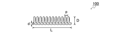
- FIG. 1 is a diagram schematically showing a medical image guidance marker of the present invention.
- FIG. 2 is a CT image of the medical image guidance marker of the present invention and the conventional marker.
- the upper row is a longitudinal image, and the lower row is a transverse image.
- FIG. 3 shows the imaging results of the medical image guidance marker of the present invention and the conventional marker by the MRI apparatus.
- the upper row is a longitudinal image, and the lower row is a transverse image.
- FIG. 4 is an ultrasonic image of the medical image guidance marker of the present invention and the conventional marker.
- the upper row is a horizontal image, and the lower row is an image tilted by about 40 degrees.
- FIG. 5 is an ultrasonic image (horizontal image) of the medical image guidance marker of the present invention and the medical image guidance marker of the comparative example.
- the medical image guidance marker of the present invention will be described with an example. However, the present invention is not limited to and limited to the following examples.
- FIG. 1 is a diagram schematically showing a medical image guidance marker according to the present invention.
- the medical image guidance marker 100 has a coil-shaped shape.
- the present invention is characterized in that the shape of the coil (wire diameter d, coil diameter D, pitch p) is defined together with the material constituting the marker.
- the medical image guidance marker of the present invention is made of an alloy having a magnetic susceptibility in the range of -13 ppm to -5 ppm.
- volume magnetic susceptibility In order to suppress artifacts, it is important that the magnetic susceptibility of the material (volume magnetic susceptibility) is close to the magnetic susceptibility of living tissue. It is not just a matter of lowering the magnetic susceptibility.
- the magnetic susceptibility of living tissue is due to its main constituent, water, which has a magnetic susceptibility of -9 ppm.
- the magnetic susceptibility is a volume magnetic susceptibility measured at a measurement temperature of 37 ° C. by a superconducting quantum interference element (SQUID) device (7T-SQUID magnetometer manufactured by Quantum Design Co., Ltd
- the shape of the medical image guidance marker of the present invention is a coil made of a material having the above-mentioned magnetic susceptibility and having a wire diameter d of 0.15 mm or more and 0.45 mm or less.
- the diameter D is in the range of 0.55 mm or more and 1.20 mm or less
- the pitch p of the coil is in the range of 0.3 mm or more and 1.5 mm or less
- 1.8 times or more of the wire diameter d of the wire It is within the range of 4 times or less.
- the pitch p is preferably in the range of 2 times or more and 3.5 times or less of the wire diameter d, and more preferably in the range of 2 times or more and 3 times or less.
- the wire diameter d is preferably in the range of 20% or more and 40% or less of the coil diameter D.
- the shape of the medical image guidance marker of the present invention for example, when applied to the prostate, is formed of wires having a wire diameter d of 0.2 mm or more and 0.3 mm or less, and has a coil diameter D of 0. It is preferable that the pitch p of the coil is within the range of 0.6 mm or more and 1.0 mm or less and the pitch p of the coil is within the range of 0.5 mm or more and 0.8 mm or less.
- the wires are wound in close contact with each other so as not to create a gap between the wires wound adjacent to the coil to form a coil. That is, the pitch p of the coil was substantially equal to the wire diameter d of the wire.
- the pitch p is increased with respect to the wire diameter d to provide a gap between the wires wound adjacent to the coil.
- the pitch p of the coil is in the range of 0.6 mm or more and 0.7 mm or less.
- the coil length L can be appropriately selected depending on the organ in which the medical image guidance marker is embedded, but when applied to the prostate, it is preferably within the range of 6 mm or more and 7 mm or less.
- the prostate due to the characteristics of the tissue around the indwelling place, if the marker is too short, it will move in the tissue. Therefore, if the marker is within the range of 6 mm or more and 7 mm or less, position stability can be obtained, which is preferable.
- the organ into which the marker of the present invention is embedded include the prostate, lung, liver, gallbladder, kidney, pancreas, breast, and the like, and the prostate can be used urgently.
- the alloy having a magnetic susceptibility in the range of -13 ppm to -5 ppm is preferably an Au-Pt alloy.
- Au-Pt alloy is a suitable material in that it can be artifact-free in MRI images. Further, if only gold (Au) is used, it is too soft when the specified coil shape is formed. Therefore, from the viewpoint of handleability, an Au-Pt alloy containing an appropriate amount of Pt is preferable.
- the Au-Pt alloy has a Pt concentration of 34% by mass or more and 36% by mass or less, and is composed of the balance Au, and further, the peak intensity (X) of the Pt (111) plane and the peak of the Au (111) plane in the X-ray diffraction analysis.
- the alloy according to Patent No. 5550027 which has an ⁇ single-phase structure in which the ratio (X / Y) to the strength (Y) is 0.01 or less, is preferable.
- the Au-Pt alloy is composed of a Pt concentration of 24% by mass or more and less than 34% by mass and the balance Au, and has a material structure in which at least a Pt-rich phase having a Pt concentration higher than that of the ⁇ phase is distributed in the ⁇ -phase matrix.
- the Pt-rich phase is made of an Au-Pt alloy having a Pt concentration of 1.2 to 3.8 times the Pt concentration of the ⁇ phase, and the area ratio of the Pt-rich phase in an arbitrary cross section is 1 to 22%. It is preferably the alloy described in Japanese Patent No. 5582484.
- Au-Pt alloys have good properties required as medical alloys such as biocompatibility, corrosion resistance and processability, and have a magnetic susceptibility suitable as an artifact-free material. Further, as described above, regarding the shape of the coil, the artifact (acoustic shadow) is reduced by providing a space between the wires wound adjacent to each other, but the physical strength due to the shape is weakened. In this regard, by using an alloy in which platinum is added to the material, the strength can be increased as compared with, for example, a coil-shaped marker of Au alone, and even the desired shape can be sufficiently strong for the application of the present invention. Obtainable.
- markers for external beam radiation therapy there are several types of markers for external beam radiation therapy on the market, but all of them were made of gold (Au). These were indwelled in the body and used for grasping the position information by pretreatment CT, for example, indwelling around the cancer lesion. This is because when placed in the center of a cancer lesion, the cancer lesion cannot be observed due to an artifact caused by a marker. Since the medical image guidance marker of the present invention does not need to consider the influence of artifacts, it can be placed in the center of a cancer lesion to directly observe the treatment course or to identify the treatment target position. ..
- the medical image guidance marker of the present invention has a shape that smoothly passes through the inside of a 16-gauge to 20-gauge image guide puncture needle.
- the surface of the medical image guidance marker of the present invention can be maintained in a smooth state by leaving the surface of the drawn alloy wire as it is. In this state, the insertion resistance when the marker is punctured and inserted into the body can be reduced as much as possible.
- fine irregularities are imparted to the surface of the medical image guidance marker. It is also possible to do.
- the medical image guidance marker of the present invention is becoming widespread in clinical practice because it is possible to keep the acoustic shadow to a minimum by providing a gap between the wires wound adjacent to the coil. It is an indispensable marker when performing a puncture procedure with ultrasonic guidance by fusing the DICOM data of a certain MRI image.
- the medical image guidance marker of the present invention can be applied not only to external beam radiation therapy but also to cancer lesion targeting therapy such as surveillance therapy. Further, the medical image guidance marker of the present invention can also be used for the purpose of alignment using a cone beam CT device in the conventional external beam radiotherapy for prostate cancer using X-rays and particle beams.
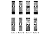
- FIG. 2 is a CT image of a medical image guidance marker (Example) of the present invention and a conventional marker (Comparative Example).
- the upper row is a longitudinal image, and the lower row is a transverse image.
- Marker A and Marker B are medical image guidance markers of the present invention.
- Marker C and Marker D are conventional (marketed) gold (Au) markers.
- Each marker is as follows.
- Example 1 Marker A Made of Au-30Pt alloy.
- the wire diameter d is 0.2 mm, the coil diameter D is 0.8 mm, and the coil pitch p is 0.6 mm.
- Example 2 Marker B Made of Au-30Pt alloy.
- the wire diameter d is 0.2 mm, the coil diameter D is 0.8 mm, and the coil pitch p is 0.7 mm.
- Marker C "VISICOIL Marker Preload" VC-076-010-PL 0.75 x 10 mm (manufactured by Seti Medical Lab Co., Ltd.) Made by Au.
- the coil diameter D is 0.75 mm, and the wires wound adjacent to each other of the coil are in close contact with each other.
- the Au-30Pt alloy used in Example 1, Example 2 and Example 3 described later is an Au-Pt alloy having a Pt concentration of 30% by mass, and is at 800 ° C. by the method described in Japanese Patent No. 5582484. It was heat-treated for 24 hours.
- the magnetic susceptibility of the alloy in the production lot used was ⁇ 7 ppm.
- the magnetic susceptibility of Au is ⁇ 34 ppm.
- the black part around the marker is an artifact.
- the medical image guidance markers of Examples 1 and 2 show almost no artifacts in both the longitudinal image and the transverse image in the CT image.
- the markers of Comparative Example 1 and Comparative Example 2 show artifacts in both the longitudinal image and the transverse image.
- the marker of the comparative example may be difficult to judge by an image due to the artifact generated by the placement of the marker. Therefore, it is sufficient for the purpose of grasping the position information by indwelling at the boundary portion of the observation area, but it is not indwelled in the observation area.
- the medical image guidance markers of Examples 1 and 2 have the minimum number of artifacts, they can be placed in the observation area.
- FIG. 3 is an imaging result of the same marker as in FIG. 2 by an MRI apparatus.
- the upper row is a longitudinal image
- the lower row is a transverse image.
- the medical image guidance markers of Examples 1 and 2 show almost no artifacts in both the longitudinal image and the transverse image in the CT image.
- the markers of Comparative Example 1 and Comparative Example 2 show artifacts in both the longitudinal image and the transverse image.
- FIG. 4 is an ultrasonic image of a medical image guidance marker (Example) of the present invention and a conventional marker (Comparative Example).
- the upper row is an ultrasonic image with the marker placed horizontally, and the lower row is an ultrasonic image with the marker tilted by about 40 ° and placed diagonally.
- Marker F is a medical image guidance marker of the present invention.
- Marker E is a conventional (marketed product) gold (Au) marker.
- Marker D in the figure is a marker of Comparative Example 2 described above. The other markers are as follows.
- Example 3 Marker F Made of Au-30Pt alloy.
- the wire diameter d is 0.3 mm
- the coil diameter D is 0.8 mm
- the coil pitch p is 0.6 mm.
- Comparative Example 3 Marker E "ACCULOC Gold Marker” (manufactured by CIVCO) Made by Au. It is a cylindrical marker with a diameter of 1.2 mm and a length of 3 mm.
- FIG. 4 shows a medical image guidance marker having a wire diameter d of 0.3 mm and a pitch p of 0.6 mm as an example, a medical image guidance marker having a wire diameter d of 0.2 mm is also shown. Similar results were obtained. In the example, when a marker with a different pitch p was created and an ultrasonic image was observed, it was found that when the pitch p was 0.6 mm or more in the horizontally indwelled state, the artifacts were further reduced. .. It was also found that in the state of being placed diagonally, the number of artifacts was further reduced in the range of pitch p of 0.5 mm to 0.8 mm.
- This marker has a linear shape before being placed in the body, but when placed in the body, it becomes a small rounded spherical shape (diameter 0.75 mm). In this spherical state, it was extremely difficult to recognize the position information of the marker on the ultrasonic image.
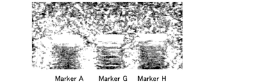
- FIG. 5 is an ultrasonic image of the medical image guidance marker (Example) of the present invention and the medical image guidance marker of the comparative example.
- FIG. 5 is an ultrasonic image in which the marker is placed horizontally.
- the Marker A, Marker G, and Marker H markers are all made of the same material (Au-30Pt), with different wire diameters d and pitch p. Marker A is the marker of Example 1 above.
- the other markers are as follows.
- Example 1 Comparative Example 4 and Comparative Example 5 are made of the same material, it can be seen that the acoustic shading is different depending on the size of the pitch p of the coil.
- an artifact acoustic shadow portion visible as a streak
- an artifact acoustic shadow in the ultrasonic image is generated. You can see that it is suppressed.
- the medical image guidance marker of Example 4 is made of Au-30Pt alloy, has a wire diameter d of 0.3 mm, a coil diameter D of 0.8 mm, and a coil pitch p of 0.7 mm.
- the medical image guidance marker of Example 5 is made of Au-30Pt alloy, has a wire diameter d of 0.3 mm, a coil diameter D of 0.8 mm, and a coil pitch p of 0.9 mm.
- the Au-30Pt alloy used in Examples 4 and 5 is an Au-Pt alloy having a Pt concentration of 30% by mass, and is heat-treated at 800 ° C. for 24 hours by the method described in Japanese Patent No. 5582484. It is a thing.
- the magnetic susceptibility of the alloy in the production lot used was -6.3 ppm.
- anesthesia Introduce thiamiral sodium 22.5 mg / kg (dosage increased or decreased depending on anesthesia status, 17-23 mg / kg) by intravenous administration
- the prostate weights of the five dogs were: Dog 1 29.4g Dog 2 20.6g Dog 3 14.7g Dog 4 11.1g Dog 5 17.1g
- the medical image guidance marker and the conventional marker of the present invention were placed in the right lobe and the left lobe of the prostate of each dog as follows.
- Dog 1 Two markers of Example 4 (coil pitch 0.7 mm) were placed in both lobes of the prostate, two markers in each lobe, but two markers placed in the right lobe were placed in the vicinity. One marker was placed at a position away from the marker. Two markers were placed on the left leaf as planned.
- Dog 2 Two markers of Example 5 (coil pitch 0.9 mm) were placed in both lobes of the prostate.
- Dog 3 One marker of Example 4 (coil pitch 0.7 mm) and one marker of Example 5 (coil pitch 0.9 mm) were placed in the right lobe of the prostate.
- Comparative Example 2 Two markers of Comparative Example 2 (“ACCULOC Gold Marker” MTNW888772 18G ⁇ 20cm 0.9 ⁇ 3mm (manufactured by CIVCO)) were placed in the left lobe of the prostate. Dog 4 One marker of Example 4 (coil pitch 0.7 mm) and one marker of Example 5 (coil pitch 0.9 mm) were placed in the right lobe of the prostate. Two markers of Comparative Example 1 (“VISICOIL marker preload” VC-076-010-PL 0.75 ⁇ 10 mm (manufactured by Seti Medical Lab Co., Ltd.)) were placed in the left lobe of the prostate.
- VISICOIL marker preload VC-076-010-PL 0.75 ⁇ 10 mm
- Example 4 coil pitch 0.7 mm
- Example 5 coil pitch 0.9 mm
- Two markers of Comparative Example 6 (“Gold Anchore” GA200-10 (manufactured by Naslund Medical)) were placed in the left lobe of the prostate.
- Dog 1 The result was that no acoustic shadow interference occurred for all five markers.
- Dog 2 Acoustic shadow interference did not occur for all four markers, and there was no difference even when compared with the markers of Example 4 having a coil pitch of 0.7 mm.
- Dog 3 In the left lobe of the prostate where the marker of Comparative Example 2 was placed, a clear acoustic shadow was observed on the marker.
- Dog 4 In the left lobe of the prostate where the marker of Comparative Example 1 was placed, it was comparable to the markers of Examples 4 and 5 from the viewpoint of acoustic shading.
- Dog 5 The marker of Comparative Example 6 placed in the left lobe of the prostate had an unclear localization (a spherical high echo area was not visualized, but a spherical echo was visualized at the marker placement site of the pin point).
- the medical image guidance marker of the present invention has good visibility during indwelling and does not cause misalignment during indwelling. From the MRI examination results, remarkable artifacts can be seen even if one marker of the comparative example is placed in the target site, but the medical image guidance marker of the present invention can be placed in many different sites of the target organ. , It was confirmed that no artifacts were seen.
- the medical image guidance marker of the present invention can be observed or diagnosed in more detail without invading the living body, and can even perform more precise treatment.
Landscapes
- Health & Medical Sciences (AREA)
- Life Sciences & Earth Sciences (AREA)
- Physics & Mathematics (AREA)
- Engineering & Computer Science (AREA)
- Nuclear Medicine, Radiotherapy & Molecular Imaging (AREA)
- General Health & Medical Sciences (AREA)
- Pathology (AREA)
- Surgery (AREA)
- Molecular Biology (AREA)
- Public Health (AREA)
- Heart & Thoracic Surgery (AREA)
- Medical Informatics (AREA)
- Biomedical Technology (AREA)
- Veterinary Medicine (AREA)
- Animal Behavior & Ethology (AREA)
- Radiology & Medical Imaging (AREA)
- High Energy & Nuclear Physics (AREA)
- Biophysics (AREA)
- Theoretical Computer Science (AREA)
- Condensed Matter Physics & Semiconductors (AREA)
- General Physics & Mathematics (AREA)
- Signal Processing (AREA)
- Chemical & Material Sciences (AREA)
- Pulmonology (AREA)
- Oral & Maxillofacial Surgery (AREA)
- Computer Vision & Pattern Recognition (AREA)
- Physiology (AREA)
- Psychiatry (AREA)
- Artificial Intelligence (AREA)
- Materials Engineering (AREA)
- Mechanical Engineering (AREA)
- Metallurgy (AREA)
- Organic Chemistry (AREA)
- Magnetic Resonance Imaging Apparatus (AREA)
- Apparatus For Radiation Diagnosis (AREA)
- Ultra Sonic Daignosis Equipment (AREA)
Priority Applications (3)
| Application Number | Priority Date | Filing Date | Title |
|---|---|---|---|
| EP20830054.1A EP3998019B1 (en) | 2019-07-10 | 2020-06-11 | Medical image guidance marker |
| JP2021530543A JP7273428B2 (ja) | 2019-07-10 | 2020-06-11 | 医療用イメージガイダンスマーカー |
| US17/625,895 US12514676B2 (en) | 2019-07-10 | 2020-06-11 | Medical image guidance marker |
Applications Claiming Priority (2)
| Application Number | Priority Date | Filing Date | Title |
|---|---|---|---|
| JP2019-128620 | 2019-07-10 | ||
| JP2019128620 | 2019-07-10 |
Publications (1)
| Publication Number | Publication Date |
|---|---|
| WO2021005955A1 true WO2021005955A1 (ja) | 2021-01-14 |
Family
ID=74114104
Family Applications (1)
| Application Number | Title | Priority Date | Filing Date |
|---|---|---|---|
| PCT/JP2020/023063 Ceased WO2021005955A1 (ja) | 2019-07-10 | 2020-06-11 | 医療用イメージガイダンスマーカー |
Country Status (4)
| Country | Link |
|---|---|
| US (1) | US12514676B2 (https=) |
| EP (1) | EP3998019B1 (https=) |
| JP (1) | JP7273428B2 (https=) |
| WO (1) | WO2021005955A1 (https=) |
Cited By (1)
| Publication number | Priority date | Publication date | Assignee | Title |
|---|---|---|---|---|
| JP2024537632A (ja) * | 2021-11-03 | 2024-10-16 | エンドマグネティクス リミテッド | イメージングおよび外科用ガイドのための磁気マーカー |
Families Citing this family (2)
| Publication number | Priority date | Publication date | Assignee | Title |
|---|---|---|---|---|
| JP7273428B2 (ja) * | 2019-07-10 | 2023-05-15 | 京都府公立大学法人 | 医療用イメージガイダンスマーカー |
| US20260060776A1 (en) * | 2024-08-27 | 2026-03-05 | Izi Medical Products, Llc | Adaptive fudicials for multi-modal radiotherapy |
Citations (11)
| Publication number | Priority date | Publication date | Assignee | Title |
|---|---|---|---|---|
| JPS5550027B2 (https=) | 1977-09-09 | 1980-12-16 | ||
| WO2007070544A2 (en) * | 2005-12-13 | 2007-06-21 | Cook Incorporated | Implantable medical device using palladium |
| JP2009502321A (ja) * | 2005-07-26 | 2009-01-29 | ボストン サイエンティフィック リミティド | 医療装置の共鳴器 |
| WO2010084948A1 (ja) * | 2009-01-24 | 2010-07-29 | 国立大学法人徳島大学 | 医療用合金及び医療用具 |
| JP4523179B2 (ja) | 1999-04-13 | 2010-08-11 | エレファント デンタル ベー.フェー. | 生物医学用の補助材または埋込材 |
| JP2010536491A (ja) | 2007-08-17 | 2010-12-02 | ミクラス エンドバスキュラー コーポレイション | 血管治療用ツイストプライマリコイル |
| JP2013106829A (ja) * | 2011-11-22 | 2013-06-06 | Kyoto Univ | 塞栓形成用コイル |
| JP5582484B1 (ja) | 2013-12-20 | 2014-09-03 | 田中貴金属工業株式会社 | 医療用合金及びその製造方法 |
| US20160058382A1 (en) * | 2014-08-28 | 2016-03-03 | Volcano Corporation | Intravascular devices, systems, and methods having an adhesive filled flexible element |
| JP2017158608A (ja) * | 2016-03-07 | 2017-09-14 | 田中貴金属工業株式会社 | 塞栓用コイル及び塞栓用コイルの製造方法 |
| JP2018526160A (ja) * | 2015-06-04 | 2018-09-13 | エンドマグネティクス リミテッド | 磁性マーカ局在化(mml)のためのマーカ材料 |
Family Cites Families (11)
| Publication number | Priority date | Publication date | Assignee | Title |
|---|---|---|---|---|
| US6544231B1 (en) * | 2000-05-22 | 2003-04-08 | Medcanica, Inc. | Catch, stop and marker assembly for a medical instrument and medical instrument incorporating the same |
| US20060293581A1 (en) * | 2005-05-12 | 2006-12-28 | Sunnybrook And Women's College Health Sciences Centre | Marker device for X-ray, ultrasound and MR imaging |
| US8175679B2 (en) * | 2007-12-26 | 2012-05-08 | St. Jude Medical, Atrial Fibrillation Division, Inc. | Catheter electrode that can simultaneously emit electrical energy and facilitate visualization by magnetic resonance imaging |
| WO2009097221A2 (en) * | 2008-01-28 | 2009-08-06 | Deringer-Ney, Inc. | Palladium-based alloys for use in the body and suitable for mri imaging |
| JP5106218B2 (ja) * | 2008-04-07 | 2012-12-26 | 学校法人慶應義塾 | 生体組織に光線を照射するためのコイル状光拡散体及びそれを含む光拡散デバイス |
| WO2011019849A1 (en) * | 2009-08-12 | 2011-02-17 | The Regents Of The University Of California | Magnetic resonance microcoil and method of use |
| CN102655824B (zh) * | 2010-03-26 | 2014-10-29 | 奥林巴斯医疗株式会社 | 医疗用支架 |
| US9743992B2 (en) * | 2012-08-23 | 2017-08-29 | Volcano Corporation | Device, system, and method utilizing a radiopaque coil for anatomical lesion length estimation |
| JP5550027B1 (ja) | 2013-06-26 | 2014-07-16 | 田中貴金属工業株式会社 | 医療用合金及びその製造方法 |
| GB2573500B (en) * | 2018-03-23 | 2020-11-04 | Endomagnetics Ltd | Magnetic markers for surgical guidance |
| JP7273428B2 (ja) * | 2019-07-10 | 2023-05-15 | 京都府公立大学法人 | 医療用イメージガイダンスマーカー |
-
2020
- 2020-06-11 JP JP2021530543A patent/JP7273428B2/ja active Active
- 2020-06-11 EP EP20830054.1A patent/EP3998019B1/en active Active
- 2020-06-11 US US17/625,895 patent/US12514676B2/en active Active
- 2020-06-11 WO PCT/JP2020/023063 patent/WO2021005955A1/ja not_active Ceased
Patent Citations (12)
| Publication number | Priority date | Publication date | Assignee | Title |
|---|---|---|---|---|
| JPS5550027B2 (https=) | 1977-09-09 | 1980-12-16 | ||
| JP4523179B2 (ja) | 1999-04-13 | 2010-08-11 | エレファント デンタル ベー.フェー. | 生物医学用の補助材または埋込材 |
| JP2009502321A (ja) * | 2005-07-26 | 2009-01-29 | ボストン サイエンティフィック リミティド | 医療装置の共鳴器 |
| WO2007070544A2 (en) * | 2005-12-13 | 2007-06-21 | Cook Incorporated | Implantable medical device using palladium |
| JP2010536491A (ja) | 2007-08-17 | 2010-12-02 | ミクラス エンドバスキュラー コーポレイション | 血管治療用ツイストプライマリコイル |
| WO2010084948A1 (ja) * | 2009-01-24 | 2010-07-29 | 国立大学法人徳島大学 | 医療用合金及び医療用具 |
| JP2013106829A (ja) * | 2011-11-22 | 2013-06-06 | Kyoto Univ | 塞栓形成用コイル |
| JP5582484B1 (ja) | 2013-12-20 | 2014-09-03 | 田中貴金属工業株式会社 | 医療用合金及びその製造方法 |
| JP2015120946A (ja) * | 2013-12-20 | 2015-07-02 | 田中貴金属工業株式会社 | 医療用合金及びその製造方法 |
| US20160058382A1 (en) * | 2014-08-28 | 2016-03-03 | Volcano Corporation | Intravascular devices, systems, and methods having an adhesive filled flexible element |
| JP2018526160A (ja) * | 2015-06-04 | 2018-09-13 | エンドマグネティクス リミテッド | 磁性マーカ局在化(mml)のためのマーカ材料 |
| JP2017158608A (ja) * | 2016-03-07 | 2017-09-14 | 田中貴金属工業株式会社 | 塞栓用コイル及び塞栓用コイルの製造方法 |
Non-Patent Citations (1)
| Title |
|---|
| See also references of EP3998019A4 |
Cited By (2)
| Publication number | Priority date | Publication date | Assignee | Title |
|---|---|---|---|---|
| JP2024537632A (ja) * | 2021-11-03 | 2024-10-16 | エンドマグネティクス リミテッド | イメージングおよび外科用ガイドのための磁気マーカー |
| JP7706648B2 (ja) | 2021-11-03 | 2025-07-11 | エンドマグネティクス リミテッド | イメージングおよび外科用ガイドのための磁気マーカー |
Also Published As
| Publication number | Publication date |
|---|---|
| EP3998019A1 (en) | 2022-05-18 |
| US12514676B2 (en) | 2026-01-06 |
| EP3998019B1 (en) | 2025-09-03 |
| US20220354615A1 (en) | 2022-11-10 |
| JPWO2021005955A1 (https=) | 2021-01-14 |
| EP3998019A4 (en) | 2023-07-05 |
| JP7273428B2 (ja) | 2023-05-15 |
Similar Documents
| Publication | Publication Date | Title |
|---|---|---|
| US8027712B2 (en) | Elongated markers for soft tissue volume identification | |
| US20060293581A1 (en) | Marker device for X-ray, ultrasound and MR imaging | |
| JP7273428B2 (ja) | 医療用イメージガイダンスマーカー | |
| Rossmeisl et al. | Frame-based stereotactic biopsy of canine brain masses: technique and clinical results in 26 cases | |
| US20130190609A1 (en) | Echogenic medical device | |
| JP2014502541A (ja) | 医学的処置中のイメージガイダンスのためのシステムおよび方法 | |
| Shinohara et al. | Technique for implantation of fiducial markers in the prostate | |
| Popowski et al. | Open magnetic resonance imaging using titanium-zirconium needles: improved accuracy for interstitial brachytherapy implants? | |
| JP2022107590A (ja) | 磁気共鳴イメージング下での治療の施行において有益な介入用医療機器及びこれに関係する方法 | |
| TR201810424T4 (tr) | Radyoterapi için tıbbi cihaz. | |
| KR20140107518A (ko) | 피듀셜 배치 시스템 및 벌어지는 스타일릿 | |
| de Vries et al. | Dedicated holmium microsphere administration device for MRI-guided interstitial brain microbrachytherapy | |
| JP5162238B2 (ja) | 生体組織における位置決め用マーカー | |
| RU2547686C2 (ru) | Способ диагностики опухолей малого таза | |
| CN103957991B (zh) | 插入人体或者动物体内的医疗装置 | |
| US20240423917A1 (en) | Use of nanoparticles for the treatment of fistulizing anoperineal lesions | |
| CN214511324U (zh) | 肺小结节定位针 | |
| CN210811592U (zh) | 肺小结节双侧定位器械 | |
| KR20110105265A (ko) | 뇌종양 영상 진단을 위한 뇌종양 유발 방법 및 그에 의한 동물 모델 | |
| Clerc-Renaud et al. | Potential for BioXmark liquid fiducial marker to improve identification of superficial component of canine oral tumors for computer-based radiation therapy planning | |
| Vries et al. | Dedicated holmium microsphere administration device for MRI-guided interstitial brain microbrachytherapy | |
| RU2811787C2 (ru) | Внутритканевый маркер для визуализации опухолей мягких тканей | |
| Zlevor et al. | CT-Guided Percutaneous Intervention: Reduction of Metal Needle Artifact with Low Atomic Number Materials in Phantom and Porcine Models | |
| Zhou et al. | Application value of computed tomography and magnetic resonance imaging three-dimensional reconstruction and digital subtraction angiography in percutaneous transhepatic cholangial drainage | |
| Okihara et al. | Development of novel artifact-less imaging-guidance marker for MRI, CT, and |
Legal Events
| Date | Code | Title | Description |
|---|---|---|---|
| 121 | Ep: the epo has been informed by wipo that ep was designated in this application |
Ref document number: 20830054 Country of ref document: EP Kind code of ref document: A1 |
|
| ENP | Entry into the national phase |
Ref document number: 2021530543 Country of ref document: JP Kind code of ref document: A |
|
| ENP | Entry into the national phase |
Ref document number: 2020830054 Country of ref document: EP Effective date: 20220210 |
|
| WWG | Wipo information: grant in national office |
Ref document number: 2020830054 Country of ref document: EP |
|
| WWG | Wipo information: grant in national office |
Ref document number: 17625895 Country of ref document: US |