WO2021005704A1 - バルブタイミング変更装置 - Google Patents
バルブタイミング変更装置 Download PDFInfo
- Publication number
- WO2021005704A1 WO2021005704A1 PCT/JP2019/027110 JP2019027110W WO2021005704A1 WO 2021005704 A1 WO2021005704 A1 WO 2021005704A1 JP 2019027110 W JP2019027110 W JP 2019027110W WO 2021005704 A1 WO2021005704 A1 WO 2021005704A1
- Authority
- WO
- WIPO (PCT)
- Prior art keywords
- spring
- housing
- valve timing
- vane rotor
- protruding portion
- Prior art date
- Legal status (The legal status is an assumption and is not a legal conclusion. Google has not performed a legal analysis and makes no representation as to the accuracy of the status listed.)
- Ceased
Links
Images



Classifications
-
- F—MECHANICAL ENGINEERING; LIGHTING; HEATING; WEAPONS; BLASTING
- F01—MACHINES OR ENGINES IN GENERAL; ENGINE PLANTS IN GENERAL; STEAM ENGINES
- F01L—CYCLICALLY OPERATING VALVES FOR MACHINES OR ENGINES
- F01L1/00—Valve-gear or valve arrangements, e.g. lift-valve gear
- F01L1/02—Valve drive
- F01L1/022—Chain drive
-
- F—MECHANICAL ENGINEERING; LIGHTING; HEATING; WEAPONS; BLASTING
- F01—MACHINES OR ENGINES IN GENERAL; ENGINE PLANTS IN GENERAL; STEAM ENGINES
- F01L—CYCLICALLY OPERATING VALVES FOR MACHINES OR ENGINES
- F01L1/00—Valve-gear or valve arrangements, e.g. lift-valve gear
- F01L1/34—Valve-gear or valve arrangements, e.g. lift-valve gear characterised by the provision of means for changing the timing of the valves without changing the duration of opening and without affecting the magnitude of the valve lift
- F01L1/344—Valve-gear or valve arrangements, e.g. lift-valve gear characterised by the provision of means for changing the timing of the valves without changing the duration of opening and without affecting the magnitude of the valve lift changing the angular relationship between crankshaft and camshaft, e.g. using helicoidal gear
- F01L1/3442—Valve-gear or valve arrangements, e.g. lift-valve gear characterised by the provision of means for changing the timing of the valves without changing the duration of opening and without affecting the magnitude of the valve lift changing the angular relationship between crankshaft and camshaft, e.g. using helicoidal gear using hydraulic chambers with variable volume to transmit the rotating force
-
- F—MECHANICAL ENGINEERING; LIGHTING; HEATING; WEAPONS; BLASTING
- F01—MACHINES OR ENGINES IN GENERAL; ENGINE PLANTS IN GENERAL; STEAM ENGINES
- F01L—CYCLICALLY OPERATING VALVES FOR MACHINES OR ENGINES
- F01L1/00—Valve-gear or valve arrangements, e.g. lift-valve gear
- F01L1/34—Valve-gear or valve arrangements, e.g. lift-valve gear characterised by the provision of means for changing the timing of the valves without changing the duration of opening and without affecting the magnitude of the valve lift
- F01L1/344—Valve-gear or valve arrangements, e.g. lift-valve gear characterised by the provision of means for changing the timing of the valves without changing the duration of opening and without affecting the magnitude of the valve lift changing the angular relationship between crankshaft and camshaft, e.g. using helicoidal gear
- F01L1/3442—Valve-gear or valve arrangements, e.g. lift-valve gear characterised by the provision of means for changing the timing of the valves without changing the duration of opening and without affecting the magnitude of the valve lift changing the angular relationship between crankshaft and camshaft, e.g. using helicoidal gear using hydraulic chambers with variable volume to transmit the rotating force
- F01L2001/3445—Details relating to the hydraulic means for changing the angular relationship
-
- F—MECHANICAL ENGINEERING; LIGHTING; HEATING; WEAPONS; BLASTING
- F01—MACHINES OR ENGINES IN GENERAL; ENGINE PLANTS IN GENERAL; STEAM ENGINES
- F01L—CYCLICALLY OPERATING VALVES FOR MACHINES OR ENGINES
- F01L1/00—Valve-gear or valve arrangements, e.g. lift-valve gear
- F01L1/34—Valve-gear or valve arrangements, e.g. lift-valve gear characterised by the provision of means for changing the timing of the valves without changing the duration of opening and without affecting the magnitude of the valve lift
- F01L1/344—Valve-gear or valve arrangements, e.g. lift-valve gear characterised by the provision of means for changing the timing of the valves without changing the duration of opening and without affecting the magnitude of the valve lift changing the angular relationship between crankshaft and camshaft, e.g. using helicoidal gear
- F01L1/3442—Valve-gear or valve arrangements, e.g. lift-valve gear characterised by the provision of means for changing the timing of the valves without changing the duration of opening and without affecting the magnitude of the valve lift changing the angular relationship between crankshaft and camshaft, e.g. using helicoidal gear using hydraulic chambers with variable volume to transmit the rotating force
- F01L2001/3445—Details relating to the hydraulic means for changing the angular relationship
- F01L2001/34483—Phaser return springs
-
- Y—GENERAL TAGGING OF NEW TECHNOLOGICAL DEVELOPMENTS; GENERAL TAGGING OF CROSS-SECTIONAL TECHNOLOGIES SPANNING OVER SEVERAL SECTIONS OF THE IPC; TECHNICAL SUBJECTS COVERED BY FORMER USPC CROSS-REFERENCE ART COLLECTIONS [XRACs] AND DIGESTS
- Y02—TECHNOLOGIES OR APPLICATIONS FOR MITIGATION OR ADAPTATION AGAINST CLIMATE CHANGE
- Y02T—CLIMATE CHANGE MITIGATION TECHNOLOGIES RELATED TO TRANSPORTATION
- Y02T10/00—Road transport of goods or passengers
- Y02T10/10—Internal combustion engine [ICE] based vehicles
- Y02T10/12—Improving ICE efficiencies
Definitions
- This disclosure relates to a valve timing changing device.
- valve timing changing device for changing the valve timing (opening / closing timing of the intake valve or the exhaust valve) of the reciprocating engine may be used in order to efficiently perform intake or exhaust in the reciprocating engine.
- Patent Document 1 discloses a valve timing changing device including a vane rotor, a housing for accommodating the vane rotor, and a spring for urging the vane rotor in the circumferential direction of the vane rotor with respect to the housing.
- a pin is press-fitted and fixed to one end surface of the vane rotor in the axial direction of the housing so that the housing receives an urging force from a spring via the pin. It is configured in.
- a retaining portion is provided on the tip end side of the pin to prevent the spring from falling off.
- At least one embodiment of the present invention aims to provide a valve timing changing device capable of suppressing spring dropout with a small number of parts.
- the valve timing changing device is A valve timing changer for changing the valve timing of a reciprocating engine.
- vane rotor A housing that houses the vane rotor and A spring that urges the vane rotor in the circumferential direction of the vane rotor with respect to the housing, with one end in contact with the housing and the other end in contact with the vane rotor.
- a first protruding portion that protrudes from the end face on the first direction side in the axial direction of the vane rotor, and one end of the spring abuts and is urged by the spring.
- a retaining portion that is provided on the first direction side of one end of the spring and extends from the first protrusion so as to restrict the movement of one end of the spring in the first direction.
- a power transmission member for transmitting power which is located on the opposite side of the vane rotor from the spring, A first fastening member that is inserted into a first fastening hole that penetrates the power transmission member in the axial direction and a second fastening hole that penetrates the housing in the axial direction to fasten the power transmission member and the housing.
- the retaining portion may be arranged within the range where the second fastening hole exists.
- the housing includes an outer peripheral protruding portion extending along the circumferential direction on the outer peripheral side of the spring so as to project in the first direction from the end face.
- the first protruding portion may be configured to connect the outer peripheral side protruding portion and the retaining portion.
- the outer peripheral side protruding portion may be integrally molded together with the first protruding portion, the retaining portion, and the housing.
- valve timing changing device in the valve timing changing device according to any one of (1) to (4) above. Assuming that the maximum value of the distance between the side surface of the first protrusion and the outer peripheral surface of the housing is A and the dimension of the first protrusion in the circumferential direction is B, B> A may be satisfied.
- a valve timing changing device capable of suppressing spring dropout with a small number of parts is provided.
- FIG. 5 is a sectional view taken along line AA of the valve timing changing device 2 shown in FIG. It is a partially enlarged view of the valve timing change device 2 shown in FIG. It is a partially enlarged view of the valve timing change device 2 shown in FIG.
- expressions such as “same”, “equal”, and “homogeneous” that indicate that things are in the same state not only represent exactly the same state, but also have tolerances or differences to the extent that the same function can be obtained. It shall also represent the state of existence.
- an expression representing a shape such as a quadrangular shape or a cylindrical shape not only represents a shape such as a quadrangular shape or a cylindrical shape in a geometrically strict sense, but also an uneven portion or chamfering within a range in which the same effect can be obtained.
- the shape including the part and the like shall also be represented.
- the expressions “equipped”, “equipped”, “equipped”, “included”, or “have” one component are not exclusive expressions that exclude the existence of other components.
- FIG. 1 is a schematic perspective view of a valve timing changing device 2 according to an embodiment of the present invention.
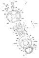
- FIG. 2 is an exploded perspective view of the valve timing changing device 2 shown in FIG.
- FIG. 3 is a front view of the valve timing changing device 2 shown in FIG.
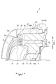
- FIG. 4 is a cross-sectional view taken along the line AA of the valve timing changing device 2 shown in FIG.
- the valve timing changing device 2 changes the valve timing of the reciprocating engine (opening / closing timing of the intake valve or the exhaust valve of the reciprocating engine) by advancing or retarding the camshaft with respect to the crankshaft (not shown). It is a phase change type variable valve mechanism.
- the valve timing changing device 2 is connected to a camshaft 20 (see FIG. 4) that drives an intake valve or an exhaust valve, and is configured to rotate coaxially with the camshaft 20.
- the valve timing changing device 2 may be, for example, for a two-wheeled vehicle, for other automobiles, or the like.
- the valve timing changing device 2 includes a vane rotor 4, a housing 6, a spring 8, a sprocket 10 (power transmission member), and a plurality of screws 12 (12A to 12D).
- the axial direction of the vane rotor 4 will be simply described as “axial direction”
- the radial direction of the vane rotor 4 will be simply described as “diameter direction”
- the circumferential direction of the vane rotor 4 will be simply described as “circumferential direction”. ..
- the first direction (direction from the sprocket 10 toward the vane rotor 4 and the housing 6) from the vane rotor 4 to the housing 6 in the axial direction is described as “forward” or simply “front”, and from the housing 6 in the axial direction.
- the second direction toward the vane rotor 4 (the direction from the housing 6 toward the vane rotor 4 and the sprocket 10) is referred to as "rear direction” or simply "rear”.
- the vane rotor 4 includes a vane rotor main body 16 and a tubular member 18.
- the vane rotor main body 16 includes a tubular portion 16a and a plurality of vane portions 16b provided on the outer peripheral side of the tubular portion 16a at intervals in the circumferential direction.
- the vane rotor main body 16 is configured to rotate coaxially with the camshaft 20 by being connected to the camshaft 20 for driving the intake valve or the exhaust valve via a bolt (not shown). ..
- the tubular member 18 has a tubular portion along a plane intersecting the axial direction so as to face the tubular portion 22 and the front surface 17 of the tubular portion 16a of the vane rotor main body 16. Includes an annular plate portion 24 arranged at the rear end of 22.
- the tubular member 18 is positioned on the front surface 17 of the tubular portion 16a by a pin 19 and rotates integrally with the vane rotor main body 16 and the camshaft 20 (see FIG. 4).
- the tubular portion 22 is formed with a slit 26 that penetrates the tubular portion 22 in the radial direction along the axial direction.
- a plurality of screws 12 fasten the sprocket 10 and the housing 6.
- the plurality of screws 12 includes four screws 12 (12A-12D).
- a plurality of through holes 36 (36A to 36D) penetrating in the axial direction are formed in the sprocket 10 at intervals in the circumferential direction, and a plurality of through holes 36 (36A to 36D) penetrating in the axial direction are formed in the front cover portion 30 of the housing 6.
- Fastening holes 38 (38A to 38D) are formed at intervals in the circumferential direction.
- a female screw is formed on the inner peripheral surface of each of the plurality of fastening holes 38.
- Each of the screws 12 is screwed into the corresponding through hole 36 and the fastening hole 38 to fasten the sprocket 10 and the housing 6. That is, the screw 12A as a fastening member is screwed into the through hole 36A and the fastening hole 38A, the screw 12B is screwed into the through hole 36B and the fastening hole 38B, and the screw 12C is screwed into the through hole 36C and the fastening hole 38C. The screw 12D is screwed into the through hole 36D and the fastening hole 38D.
- the housing 6 accommodates the vane rotor 4, and has a tubular portion 28 surrounding the vane rotor 4 in the circumferential direction and the front side of a plurality of vane portions 16b (see FIG. 2).
- a tubular portion 28 surrounding the vane rotor 4 in the circumferential direction and the front side of a plurality of vane portions 16b (see FIG. 2).
- an annular front cover portion 30 arranged along a plane orthogonal to the axial direction so as to cover.
- the front end surface 6a (front end surface of the front cover portion 30) in the axial direction is provided with a first projecting portion 32 projecting forward from the end surface 6a.
- a retaining portion 34 extending inward in the radial direction from the first protruding portion 32 is formed.
- the first protruding portion 32 and the retaining portion 34 are integrally molded with the same material together with the housing 6 by die casting.
- the tubular portion 28, the front cover portion 30, the first protruding portion 32, and the retaining portion 34 are integrally molded as one component that cannot be separated without being damaged.
- the spring 8 is assembled so as to urge the vane rotor 4 with respect to the housing 6 in the circumferential direction.
- the spring 8 is composed of a mainspring (swirl spring) and includes a spiral portion 8a (spring portion) having a spiral shape.
- One end 8b of the spring 8 extends from the spiral portion 8a in a direction intersecting the circumferential direction, and is hooked and held by the slit 26 of the vane rotor 4.
- one end 8b of the spring 8 is bent from the inner peripheral side portion of the spiral portion 8a and extends inward in the radial direction in the slit 26 along the radial direction.
- the wall surface 26a of the vane rotor 4 receives an urging force from one end 8b of the spring 8 toward one side in the circumferential direction (clockwise in the axial direction from the front side). That is, the vane rotor 4 is urged to one side in the circumferential direction by the spring 8.
- the other end 8c of the spring 8 extends from the spiral portion 8a in a direction intersecting the circumferential direction, and is hooked and held by the side surface 32a of the first protruding portion 32.
- the first protruding portion 32 functions as a spring hook for hooking the spring 8.
- the other end 8c of the spring 8 is bent from the outer peripheral side portion of the spiral portion 8a and extends along the radial direction toward the outside in the radial direction, and the side surface of the first protruding portion 32. It is in contact with 32a.
- the side surface 32a of the first protruding portion 32 receives an urging force from the other end 8c of the spring 8 toward the other side in the circumferential direction (counterclockwise in the axial direction from the front side). That is, the first protruding portion 32 is urged to the other side in the circumferential direction by the spring 8.
- the vane rotor 4 is rotated relative to the housing 6 in the direction of the urging force of the spring 8 or in the direction opposite to the urging force by the hydraulic pressure as the drive source, so that the vane rotor 4 with respect to the housing 6 is rotated.
- the relative phase of 4 is changed.
- the camshaft advances or retards with respect to the crankshaft (not shown), and the valve timing of the reciprocating engine is changed.
- the retaining portion 34 is provided on the front side of the other end portion 8c of the spring 8, and is first so as to restrict the forward movement of the other end portion 8c of the spring 8. It extends inward in the radial direction from the protrusion 32. By restricting the forward movement of the other end 8c of the spring 8, the retaining portion 34 prevents the spring 8 from coming off from the housing 6 toward the front side in the axial direction and falling off.
- the retaining portion 34 is formed in a plate shape so as to project from the first protruding portion 32 toward the spring 8 side along a plane orthogonal to the axial direction. As shown in FIG. 3, the retaining portion 34 overlaps with at least a part of the spring 8 in the axial view. Further, the retaining portion 34 is arranged within the range where the fastening hole 38A exists in the axial view.
- the sprocket 10 is arranged on the opposite side of the vane rotor 4 from the spring 8, that is, on the rear side of the vane rotor 4.
- a gear row 10a is formed on the outer peripheral surface of the sprocket 10.
- a roller chain (not shown) for transmitting power from the crankshaft of a reciprocating engine (not shown) is wound around the gear row 10a, and the power from the crankshaft is transmitted to the sprocket 10 via the gear row 10a.
- the relative phase of the vane rotor 4 with respect to the phase of the sprocket 10 can be fixed by a lock mechanism (for example, a lock pin) (not shown).
- the housing 6 has at least one outer peripheral protruding portion 40 extending along the circumferential direction from the end surface 6a of the housing 6 to the outer peripheral side of the spring 8 so as to project forward.
- the housing 6 includes a plurality of peripheral protrusions 40 (40A-40C) that are spaced apart in the circumferential direction.
- Each of the outer peripheral side protrusions 40 (40A to 40C) is formed in an arc shape in the axial direction, and the thickness of the outer peripheral side protrusion 40 (40A to 40C) in the radial direction is constant at each position in the circumferential direction. It has become.
- the first protruding portion 32 is formed so as to connect the outer peripheral side protruding portion 40A and the retaining portion 34 among the plurality of outer peripheral side protruding portions 40 (40A to 40C).
- the outer peripheral side protruding portion 40 (40A to 40C) is integrally molded with the same material together with the first protruding portion 32, the retaining portion 34, and the housing 6.
- the outer peripheral side protruding portion 40 (40A to 40C), the tubular portion 28, the front cover portion 30, the first protruding portion 32, and the retaining portion 34 as a whole cannot be separated without being damaged. It is molded as a part.
- the front end surface 34a of the retaining portion 34, the front end surface (top surface) 32b of the first protruding portion 32, and the front end surface (top surface) 40a of the outer peripheral side protruding portion 40A are on the same plane. It is formed.
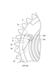
- FIG. 5 is a partially enlarged view of the valve timing changing device 2 shown in FIG.
- the maximum value of the distance between the side surface 32a of the first protrusion 32 and the outer peripheral surface 6b of the housing 6 (the outer peripheral surface of the tubular portion 28) is set to A, and the dimension of the first protruding portion 32 in the circumferential direction.
- B the first protruding portion 32 is formed so as to satisfy B> A.
- FIG. 6 is a partially enlarged view of the valve timing changing device 2 shown in FIG.
- the width at which the retaining portion 34 and the spring 8 overlap in the thickness direction of the spring 8 is C and the thickness of the spring 8 is D in the axial view, the retaining portion 34 is , C ⁇ D / 2 is formed.
- valve timing changing device 2 since the first protruding portion 32 and the retaining portion 34 are integrally molded together with the housing 6, the valve timing changing in which the housing and the pin provided with the retaining portion are configured as separate parts. Compared with the device (see, for example, Patent Document 1), the spring 8 can be suppressed from falling off with a smaller number of parts, and the valve timing changing device 2 can be reduced in cost.
- the step of assembling the pin provided with the retaining portion to the housing by press fitting or the like becomes unnecessary, and the valve timing is eliminated. Since the number of steps for assembling the changing device can be reduced, the cost of the valve timing changing device 2 can be reduced in this respect as well.
- the retaining portion 34 is arranged within the range where the fastening hole 38A exists. Therefore, the retaining portion 34 can be easily integrally molded together with the first protruding portion 32 and the housing with a simple mold structure without requiring an undercut treatment.
- the first protruding portion 32 is configured to connect the outer peripheral side protruding portion 40A extending along the circumferential direction to the outer peripheral side of the spring 8 and the retaining portion 34. There is. Therefore, the rigidity of the outer peripheral side protruding portion 40A is utilized to prevent the first protruding portion 32 from being deformed by the urging force from the spring 8 while suppressing the spring 8 from interfering with the surrounding members by the outer peripheral side protruding portion 40A. It can be effectively suppressed.
- the outer peripheral side protruding portion 40 (40A to 40C) is integrally molded together with the first protruding portion 32, the retaining portion 34, and the housing 6. Therefore, with a small number of parts, the outer peripheral side protruding portion 40A suppresses the spring 8 from interfering with the surrounding members, and the outer peripheral side protruding portion 32 prevents the first protruding portion 32 from being deformed by the urging force from the spring 8. It can be effectively suppressed by utilizing the rigidity of 40A.
- the dimension B of the first protruding portion 32 in the circumferential direction is larger than the maximum value A of the distance between the side surface 32a of the first protruding portion 32 and the outer peripheral surface 6b of the housing 6.
- the deformation of the first protrusion 32 due to the urging force in the circumferential direction from the spring 8 is more effective than when B is the maximum value A or less (for example, when the cross-sectional shape orthogonal to the axial direction of the first protrusion 32 is circular). Can be suppressed.
- the width C at which the retaining portion 34 and the spring 8 overlap and the thickness D of the spring 8 satisfy C ⁇ D / 2, so that the spring 8 is formed. It is possible to effectively prevent the retaining portion 34 from falling off in the axial direction.
- the present invention is not limited to the above-described embodiment, and includes a modification of the above-described embodiment and a combination of these embodiments as appropriate.
- the flood control is exemplified as the drive source of the vane rotor 4, but the drive source of the vane rotor 4 is not limited to the hydraulic pressure and may be a motor or the like.
- the mainspring spring is exemplified as the spring 8, but the spring is not limited to the mainspring spring, and may be another spring such as a torsion coil spring.
- a mainspring When a mainspring is used as the spring 8, it may be a contact type mainspring or a non-contact type mainspring.
- the configuration in which the vane rotor 4 side is connected to the camshaft 20 and the housing 6 side is connected to the crankshaft is illustrated, but the vane rotor side is connected to the crankshaft and the housing 6 side is connected to the camshaft. May be good. That is, in the above-described embodiment, the configuration in which the rotational force of the crankshaft (not shown) transmitted to the sprocket 10 is transmitted from the vane rotor 4 to the camshaft 20 to rotate the camshaft 20 has been exemplified, but other embodiments have been made. Then, the rotational force of the crankshaft (not shown) transmitted to the vane rotor may be transmitted to the camshaft via a sprocket or other power transmission member to rotate the camshaft.
Landscapes
- Engineering & Computer Science (AREA)
- Mechanical Engineering (AREA)
- General Engineering & Computer Science (AREA)
- Valve Device For Special Equipments (AREA)
Abstract
バルブタイミング変更装置2であって、ベーンロータ4と、ベーンロータを収容するハウジング6と、一端部8bがハウジングに当接するとともに他端部8cがベーンロータに当接し、ベーンロータをハウジングに対してベーンロータの周方向に付勢するスプリング8と、ハウジングにおいてベーンロータの軸方向における第1方向側の端面6aから突出し、スプリングの一端部が当接してスプリングに付勢される第1突出部32と、スプリングの一端部よりも第1方向側に設けられ、スプリングの一端部の第1方向への移動を規制するように第1突出部から延在する抜け止め部34と、を備え、第1突出部及び抜け止め部は、ハウジングとともに一体成形されている。
Description
本開示は、バルブタイミング変更装置に関する。
従来、レシプロエンジンにおいて効率の良い吸気又は排気を行うために、レシプロエンジンのバルブタイミング(吸気バルブ又は排気バルブの開閉タイミング)を変更するバルブタイミング変更装置が用いられる場合がある。
特許文献1には、ベーンロータと、ベーンロータを収容するハウジングと、ベーンロータをハウジングに対してベーンロータの周方向に付勢するスプリングと、を備えるバルブタイミング変更装置が開示されている。
特許文献1に記載されるバルブタイミング変更装置では、ハウジングのうちベーンロータの軸方向における一方側の端面にピンが圧入されて固定されており、ハウジングは、ピンを介してスプリングから付勢力を受けるように構成されている。また、ピンの先端側にスプリングの脱落防止のための抜け止め部が設けられている。
特許文献1に記載のバルブタイミング変更装置では、ハウジングと抜け止め部が設けられたピンとが別部品として構成されているため、バルブタイミング変更装置の部品点数が多くなり、バルブタイミング変更装置の構成が複雑化して高コスト化を招いていた。
上述の事情に鑑みて、本発明の少なくとも一実施形態は、少ない部品点数でスプリングの脱落を抑制可能なバルブタイミング変更装置を提供することを目的とする。
(1)本発明の少なくとも一実施形態に係るバルブタイミング変更装置は、
レシプロエンジンのバルブタイミングを変更するためのバルブタイミング変更装置であって、
ベーンロータと、
ベーンロータを収容するハウジングと、
一端部がハウジングに当接するとともに他端部がベーンロータに当接し、ベーンロータをハウジングに対してベーンロータの周方向に付勢するスプリングと、
ハウジングにおいてベーンロータの軸方向における第1方向側の端面から突出し、スプリングの一端部が当接してスプリングに付勢される第1突出部と、
スプリングの一端部よりも第1方向側に設けられ、スプリングの一端部の第1方向への移動を規制するように第1突出部から延在する抜け止め部と、
を備え、
第1突出部及び抜け止め部は、ハウジングとともに一体成形されている。
レシプロエンジンのバルブタイミングを変更するためのバルブタイミング変更装置であって、
ベーンロータと、
ベーンロータを収容するハウジングと、
一端部がハウジングに当接するとともに他端部がベーンロータに当接し、ベーンロータをハウジングに対してベーンロータの周方向に付勢するスプリングと、
ハウジングにおいてベーンロータの軸方向における第1方向側の端面から突出し、スプリングの一端部が当接してスプリングに付勢される第1突出部と、
スプリングの一端部よりも第1方向側に設けられ、スプリングの一端部の第1方向への移動を規制するように第1突出部から延在する抜け止め部と、
を備え、
第1突出部及び抜け止め部は、ハウジングとともに一体成形されている。
(2)幾つかの実施形態では、上記(1)に記載のバルブタイミング変更装置において、
ベーンロータを挟んでスプリングと反対側に配置された、動力を伝達するための動力伝達部材と、
動力伝達部材を軸方向に貫通する第1締結穴及びハウジングを軸方向に貫通する第2締結穴に挿通されて動力伝達部材とハウジングとを締結する第1締結部材と、
を更に備え、
軸方向視において、抜け止め部は、第2締結穴の存在する範囲内に配置されてもよい。
ベーンロータを挟んでスプリングと反対側に配置された、動力を伝達するための動力伝達部材と、
動力伝達部材を軸方向に貫通する第1締結穴及びハウジングを軸方向に貫通する第2締結穴に挿通されて動力伝達部材とハウジングとを締結する第1締結部材と、
を更に備え、
軸方向視において、抜け止め部は、第2締結穴の存在する範囲内に配置されてもよい。
(3)幾つかの実施形態では、上記(1)又は(2)に記載のバルブタイミング変更装置において、
ハウジングは、端面から第1方向に突出するようにスプリングの外周側に周方向に沿って延在する外周側突出部を含み、
第1突出部は、外周側突出部と抜け止め部とを接続するように構成されてもよい。
ハウジングは、端面から第1方向に突出するようにスプリングの外周側に周方向に沿って延在する外周側突出部を含み、
第1突出部は、外周側突出部と抜け止め部とを接続するように構成されてもよい。
(4)幾つかの実施形態では、上記(3)に記載のバルブタイミング変更装置において、
外周側突出部は、第1突出部、抜け止め部及びハウジングとともに一体成形されてもよい。
外周側突出部は、第1突出部、抜け止め部及びハウジングとともに一体成形されてもよい。
(5)幾つかの実施形態では、上記(1)乃至(4)の何れかに記載のバルブタイミング変更装置において、
第1突出部の側面とハウジングの外周面との距離の最大値をA、周方向における第1突出部の寸法をBとすると、B>Aを満たしてもよい。
第1突出部の側面とハウジングの外周面との距離の最大値をA、周方向における第1突出部の寸法をBとすると、B>Aを満たしてもよい。
(6)幾つかの実施形態では、上記(1)乃至(5)の何れかに記載のバルブタイミング変更装置において、
軸方向視において、抜け止め部とスプリングとがスプリングの太さ方向にオーバーラップする幅をC、スプリングの太さをDとすると、
C≧D/2を満たしてもよい。
軸方向視において、抜け止め部とスプリングとがスプリングの太さ方向にオーバーラップする幅をC、スプリングの太さをDとすると、
C≧D/2を満たしてもよい。
本発明の少なくとも一つの実施形態によれば、少ない部品点数でスプリングの脱落を抑制可能なバルブタイミング変更装置が提供される。
以下、添付図面を参照して本発明の幾つかの実施形態について説明する。ただし、実施形態として記載されている又は図面に示されている構成部品の寸法、材質、形状、その相対的配置等は、本発明の範囲をこれに限定する趣旨ではなく、単なる説明例にすぎない。
例えば、「ある方向に」、「ある方向に沿って」、「平行」、「直交」、「中心」、「同心」或いは「同軸」等の相対的或いは絶対的な配置を表す表現は、厳密にそのような配置を表すのみならず、公差、若しくは、同じ機能が得られる程度の角度や距離をもって相対的に変位している状態も表すものとする。
例えば、「同一」、「等しい」及び「均質」等の物事が等しい状態であることを表す表現は、厳密に等しい状態を表すのみならず、公差、若しくは、同じ機能が得られる程度の差が存在している状態も表すものとする。
例えば、四角形状や円筒形状等の形状を表す表現は、幾何学的に厳密な意味での四角形状や円筒形状等の形状を表すのみならず、同じ効果が得られる範囲で、凹凸部や面取り部等を含む形状も表すものとする。
一方、一の構成要素を「備える」、「具える」、「具備する」、「含む」、又は、「有する」という表現は、他の構成要素の存在を除外する排他的な表現ではない。
例えば、「ある方向に」、「ある方向に沿って」、「平行」、「直交」、「中心」、「同心」或いは「同軸」等の相対的或いは絶対的な配置を表す表現は、厳密にそのような配置を表すのみならず、公差、若しくは、同じ機能が得られる程度の角度や距離をもって相対的に変位している状態も表すものとする。
例えば、「同一」、「等しい」及び「均質」等の物事が等しい状態であることを表す表現は、厳密に等しい状態を表すのみならず、公差、若しくは、同じ機能が得られる程度の差が存在している状態も表すものとする。
例えば、四角形状や円筒形状等の形状を表す表現は、幾何学的に厳密な意味での四角形状や円筒形状等の形状を表すのみならず、同じ効果が得られる範囲で、凹凸部や面取り部等を含む形状も表すものとする。
一方、一の構成要素を「備える」、「具える」、「具備する」、「含む」、又は、「有する」という表現は、他の構成要素の存在を除外する排他的な表現ではない。
図1は、本発明の一実施形態に係るバルブタイミング変更装置2の概略斜視図である。図2は、図1に示したバルブタイミング変更装置2の分解斜視図である。図3は、図1に示したバルブタイミング変更装置2の正面図である。図4は、図1に示したバルブタイミング変更装置2のA-A断面図である。
バルブタイミング変更装置2は、不図示のクランクシャフトに対してカムシャフトを進角又は遅角させることで、不図示のレシプロエンジンのバルブタイミング(レシプロエンジンの吸気バルブ又は排気バルブの開閉タイミング)を変化させる位相変化型の可変バルブ機構である。バルブタイミング変更装置2は、吸気バルブ又は排気バルブを駆動するカムシャフト20(図4参照)に連結されてカムシャフト20と同軸上で回転するように構成される。バルブタイミング変更装置2は、例えば二輪車用であってもよいし、その他の自動車用等であってもよい。
例えば図2に示すように、バルブタイミング変更装置2は、ベーンロータ4、ハウジング6、スプリング8、スプロケット10(動力伝達部材)及び複数のスクリュー12(12A~12D)を備える。
以下では、ベーンロータ4の軸方向を単に「軸方向」と記載し、ベーンロータ4の径方向を単に「径方向」と記載し、ベーンロータ4の周方向を単に「周方向」と記載することとする。また、軸方向のうちベーンロータ4からハウジング6に向かう第1方向(スプロケット10からベーンロータ4及びハウジング6に向かう方向)を「前方向」又は単に「前」と記載し、軸方向のうちハウジング6からベーンロータ4に向かう第2方向(ハウジング6からベーンロータ4及びスプロケット10に向かう方向)を「後方向」又は単に「後」と記載することとする。
例えば図2に示すように、ベーンロータ4は、ベーンロータ本体16及び筒状部材18を含む。ベーンロータ本体16は、筒状部16aと、筒状部16aの外周側に周方向に間隔を空けて設けられた複数のベーン部16bとを含む。図4に示すように、ベーンロータ本体16は、吸気バルブ又は排気バルブを駆動するカムシャフト20に不図示のボルトを介して連結されることによりカムシャフト20と同軸上で回転するように構成される。
例えば図2に示すように、筒状部材18は、筒状部22と、ベーンロータ本体16の筒状部16aの前側の面17と対向するように軸方向と交差する平面に沿って筒状部22の後端に配置された環状のプレート部24とを含む。筒状部材18は、筒状部16aの前側の面17にピン19で位置決めされてベーンロータ本体16及びカムシャフト20(図4参照)と一体で回転する。筒状部22には、筒状部22を径方向に貫通するスリット26が軸方向に沿って形成されている。
例えば図2に示すように、複数のスクリュー12は、スプロケット10とハウジング6とを締結する。図示する例示的形態では、複数のスクリュー12は、4つのスクリュー12(12A~12D)を含む。スプロケット10には、軸方向に貫通する複数の貫通穴36(36A~36D)が周方向に間隔を空けて形成されており、ハウジング6のフロントカバー部30には、軸方向に貫通する複数の締結穴38(38A~38D)が周方向に間隔を空けて形成されている。複数の締結穴38の各々の内周面には、雌ねじが形成されている。スクリュー12の各々は、対応する貫通穴36及び締結穴38に捩じ込まれてスプロケット10とハウジング6とを締結している。すなわち、締結部材としてのスクリュー12Aは貫通穴36A及び締結穴38Aに捩じ込まれ、スクリュー12Bは貫通穴36B及び締結穴38Bに捩じ込まれ、スクリュー12Cは貫通穴36C及び締結穴38Cに捩じ込まれ、スクリュー12Dは貫通穴36D及び締結穴38Dに捩じ込まれる。
例えば図1及び図4に示すように、ハウジング6は、ベーンロータ4を収容しており、ベーンロータ4を周方向に囲繞する筒状部28と、複数のベーン部16b(図2参照)の前側を覆うように軸方向と直交する平面に沿って配置された環状のフロントカバー部30とを含む。
ハウジング6において軸方向における前側の端面6a(フロントカバー部30の前側の端面)には、端面6aから前方向に突出する第1突出部32が設けられている。第1突出部32の前側端には、第1突出部32から径方向における内側に向けて延在する抜け止め部34が形成されている。
第1突出部32及び抜け止め部34は、ハウジング6とともにダイカスト成形により同一材料で一体成形されている。換言すれば、筒状部28、フロントカバー部30、第1突出部32及び抜け止め部34は、全体で、破損せずに分離することができない一部品として成形されている。
例えば図1に示すように、スプリング8は、ベーンロータ4をハウジング6に対して周方向に付勢するように組み付けられている。図示する例示的な形態では、スプリング8は、ぜんまいばね(渦巻ばね)によって構成されており、渦巻き形状を有する渦巻き部8a(ばね部)を含む。スプリング8の一端部8bは、渦巻き部8aから周方向と交差する方向に延在しており、ベーンロータ4のスリット26に引っ掛けられて保持されている。図示する形態では、スプリング8の一端部8bは、渦巻き部8aの内周側部分から折り曲げられて径方向における内側に向けてスリット26内に径方向に沿って延在しており、スリット26を形成する一対の壁面のうち一方の壁面26aに当接している。ベーンロータ4の壁面26aは、スプリング8の一端部8bから周方向における一方側(前側からの軸方向視において時計回りの方向)への付勢力を受けている。すなわち、ベーンロータ4は、スプリング8によって周方向における一方側に付勢されている。
スプリング8の他端部8cは、渦巻き部8aから周方向と交差する方向に延在しており、第1突出部32の側面32aに引っ掛けられて保持されている。このように、第1突出部32は、スプリング8を引っ掛けるためのスプリングフックとして機能する。図示する形態では、スプリング8の他端部8cは、渦巻き部8aの外周側部分から折り曲げられて径方向における外側に向けて径方向に沿って延在しており、第1突出部32の側面32aに当接している。第1突出部32の側面32aは、スプリング8の他端部8cから周方向における他方側(前側からの軸方向視において反時計回りの方向)への付勢力を受けている。すなわち、第1突出部32は、スプリング8によって周方向における他方側に付勢されている。
上記バルブタイミング変更装置2では、駆動源としての油圧によってベーンロータ4をハウジング6に対してスプリング8の付勢力の方向又は付勢力と反対の方向に相対的に回動させることにより、ハウジング6に対するベーンロータ4の相対的な位相が変更される。これにより、不図示のクランクシャフトに対してカムシャフトが進角又は遅角して、レシプロエンジンのバルブタイミングが変更される。
例えば図4に示すように、抜け止め部34は、スプリング8の他端部8cよりも前側に設けられており、スプリング8の他端部8cの前方向への移動を規制するように第1突出部32から径方向における内側に向けて延在している。抜け止め部34は、スプリング8の他端部8cの前方向への移動を規制することにより、スプリング8がハウジング6から軸方向における前側に抜けて脱落することを抑制する。図示する例示的形態では、抜け止め部34は、軸方向と直交する平面に沿って第1突出部32からスプリング8側に突出するように板状に形成されている。図3に示すように、抜け止め部34は、軸方向視において、スプリング8の少なくとも一部とオーバーラップしている。また、抜け止め部34は、軸方向視において、締結穴38Aの存在する範囲内に配置されている。
例えば図4に示すように、スプロケット10は、ベーンロータ4を挟んでスプリング8と反対側、すなわちベーンロータ4の後側に配置されている。スプロケット10の外周面にはギア列10aが形成されている。ギア列10aには、不図示のレシプロエンジンのクランクシャフトから動力を伝達するための不図示のローラーチェーンが巻かれて、クランクシャフトからの動力がギア列10aを介してスプロケット10に伝達される。スプロケット10の位相(ハウジング6の位相)に対するベーンロータ4の相対的な位相は、不図示のロック機構(例えばロックピン)により固定可能となっている。
例えば図1及び図2に示すように、ハウジング6は、ハウジング6の端面6aから前方向に突出するようにスプリング8の外周側に周方向に沿って延在する少なくとも1つの外周側突出部40を含む。図示する例示的形態では、ハウジング6は、周方向に間隔を空けて配置された複数の外周側突出部40(40A~40C)を含む。外周側突出部40(40A~40C)の各々は、軸方向視において円弧状に形成されており、径方向における外周側突出部40(40A~40C)の厚さは周方向の各位置で一定となっている。第1突出部32は、複数の外周側突出部40(40A~40C)のうち外周側突出部40Aと抜け止め部34とを接続するように形成されている。
また、外周側突出部40(40A~40C)は、第1突出部32、抜け止め部34及びハウジング6とともに同一材料で一体成形されている。換言すれば、外周側突出部40(40A~40C)、筒状部28、フロントカバー部30、第1突出部32及び抜け止め部34は、全体で、破損せずに分離することができない一部品として成形されている。また、抜け止め部34における前側の端面34aと、第1突出部32における前側の端面(頂面)32bと、外周側突出部40Aにおける前側の端面(頂面)40aとは、同一平面上に形成されている。
図5は、図3に示したバルブタイミング変更装置2の部分拡大図である。
図示する例示的形態では、第1突出部32の側面32aとハウジング6の外周面6b(筒状部28の外周面)との距離の最大値をA、周方向における第1突出部32の寸法をBとすると、第1突出部32は、B>Aを満たすように形成されている。
図示する例示的形態では、第1突出部32の側面32aとハウジング6の外周面6b(筒状部28の外周面)との距離の最大値をA、周方向における第1突出部32の寸法をBとすると、第1突出部32は、B>Aを満たすように形成されている。
図6は、図3に示したバルブタイミング変更装置2の部分拡大図である。
図示する例示的形態では、軸方向視において、抜け止め部34とスプリング8とがスプリング8の太さ方向にオーバーラップする幅をC、スプリング8の太さをDとすると、抜け止め部34は、C≧D/2を満たすように形成されている。
図示する例示的形態では、軸方向視において、抜け止め部34とスプリング8とがスプリング8の太さ方向にオーバーラップする幅をC、スプリング8の太さをDとすると、抜け止め部34は、C≧D/2を満たすように形成されている。
次に、上述したバルブタイミング変更装置2が奏する作用効果について説明する。
上述したバルブタイミング変更装置2では、第1突出部32及び抜け止め部34がハウジング6とともに一体成形されているため、ハウジングと抜け止め部が設けられたピンとが別部品として構成されたバルブタイミング変更装置(例えば特許文献1参照)と比較して、少ない部品点数でスプリング8の脱落を抑制することができ、バルブタイミング変更装置2の低コスト化が可能となる。
上述したバルブタイミング変更装置2では、第1突出部32及び抜け止め部34がハウジング6とともに一体成形されているため、ハウジングと抜け止め部が設けられたピンとが別部品として構成されたバルブタイミング変更装置(例えば特許文献1参照)と比較して、少ない部品点数でスプリング8の脱落を抑制することができ、バルブタイミング変更装置2の低コスト化が可能となる。
また、ハウジングと抜け止め部が設けられたピンとが別部品として構成されたバルブタイミング変更装置と比較して、抜け止め部が設けられたピンをハウジングに圧入等により組み付ける工程が不要となり、バルブタイミング変更装置の組み立て工数を削減することができるため、この点においてもバルブタイミング変更装置2の低コスト化が可能となる。
また、図3に示したように、軸方向視において、抜け止め部34は、締結穴38Aの存在する範囲内に配置されている。このため、アンダーカット処理を要することなく簡素な金型構造で、抜け止め部34を第1突出部32及びハウジングとともに容易に一体成型することができる。
また、図1に示したように、第1突出部32は、スプリング8の外周側に周方向に沿って延在する外周側突出部40Aと抜け止め部34とを接続するように構成されている。このため、スプリング8が周囲の部材と干渉することを外周側突出部40Aによって抑制しつつ、スプリング8からの付勢力で第1突出部32が変形することを外周側突出部40Aの剛性を利用して効果的に抑制することができる。
また、図1に示したように、外周側突出部40(40A~40C)は、第1突出部32、抜け止め部34及びハウジング6とともに一体成形されている。このため、少ない部品点数で、スプリング8が周囲の部材と干渉することを外周側突出部40Aによって抑制しつつ、スプリング8からの付勢力で第1突出部32が変形することを外周側突出部40Aの剛性を利用して効果的に抑制することができる。
また、図5に示したように、周方向における第1突出部32の寸法Bが第1突出部32の側面32aとハウジング6の外周面6bとの距離の最大値Aよりも大きいため、寸法Bが最大値A以下の場合(例えば第1突出部32の軸方向に直交する断面形状が円形の場合)よりも、スプリング8からの周方向の付勢力による第1突出部32の変形を効果的に抑制することができる。
また、図6に示したように、軸方向視において、抜け止め部34とスプリング8とがオーバーラップする幅Cとスプリング8の太さDとがC≧D/2を満たすため、スプリング8が抜け止め部34から軸方向に脱落することを効果的に抑制することができる。
本発明は上述した実施形態に限定されることはなく、上述した実施形態に変形を加えた形態や、これらの形態を適宜組み合わせた形態も含む。
例えば、上述した実施形態では、ベーンロータ4の駆動源として油圧を例示したが、ベーンロータ4の駆動源は油圧に限らずモータ等であってもよい。
また、上述した実施形態では、スプリング8としてぜんまいばねを例示したが、スプリングは、ぜんまいばねに限らず、例えばねじりコイルばね等の他のスプリングであってもよい。また、スプリング8としてぜんまいばねを用いる場合には、接触型ぜんまいばねであってもよいし、非接触型ぜんまいばねであってもよい。
また、上述した実施形態では、ベーンロータ4側がカムシャフト20に連結されてハウジング6側がクランクシャフトに連結される構成を例示したが、ベーンロータ側がクランクシャフトに連結されてハウジング6側がカムシャフトに連結されてもよい。すなわち、上述した実施形態では、スプロケット10に伝達された不図示のクランクシャフトの回転力をベーンロータ4からカムシャフト20に伝達して該カムシャフト20を回転させる構成を例示したが、他の実施形態では、ベーンロータに伝達された不図示のクランクシャフトの回転力をスプロケット又はその他の動力伝達部材を介してカムシャフトに伝達して該カムシャフトを回転させてもよい。
2 バルブタイミング変更装置
4 ベーンロータ
6 ハウジング
6a 端面
6b 外周面
8 スプリング
8b 一端部
8c 他端部
10 スプロケット(動力伝達部材)
12A スクリュー(締結部材)
32 第1突出部
32a 側面
34 抜け止め部
38A 締結穴
40A 外周側突出部
4 ベーンロータ
6 ハウジング
6a 端面
6b 外周面
8 スプリング
8b 一端部
8c 他端部
10 スプロケット(動力伝達部材)
12A スクリュー(締結部材)
32 第1突出部
32a 側面
34 抜け止め部
38A 締結穴
40A 外周側突出部
Claims (6)
- レシプロエンジンのバルブタイミングを変更するためのバルブタイミング変更装置であって、
ベーンロータと、
前記ベーンロータを収容するハウジングと、
一端部が前記ハウジングに当接するとともに他端部が前記ベーンロータに当接し、前記ベーンロータを前記ハウジングに対して前記ベーンロータの周方向に付勢するスプリングと、
前記ハウジングにおいて前記ベーンロータの軸方向における第1方向側の端面から突出し、前記スプリングの前記一端部が当接して前記スプリングに付勢される第1突出部と、
前記スプリングの前記一端部よりも前記第1方向側に設けられ、前記スプリングの前記一端部の前記第1方向への移動を規制するように前記第1突出部から延在する抜け止め部と、
を備え、
前記第1突出部及び前記抜け止め部は、前記ハウジングとともに一体成形された、バルブタイミング変更装置。 - 前記ベーンロータを挟んで前記スプリングと反対側に配置された、動力を伝達するための動力伝達部材と、
前記ハウジングを前記軸方向に貫通する締結穴に挿通されて前記動力伝達部材と前記ハウジングとを締結する締結部材と、
を更に備え、
前記軸方向視において、前記抜け止め部は、前記締結穴の存在する範囲内に配置された、請求項1に記載のバルブタイミング変更装置。 - 前記ハウジングは、前記端面から前記第1方向に突出するように前記スプリングの外周側に前記周方向に沿って延在する外周側突出部を含み、
前記第1突出部は、前記外周側突出部と前記抜け止め部とを接続するように構成された、請求項1又は2に記載のバルブタイミング変更装置。 - 前記外周側突出部は、前記第1突出部、前記抜け止め部及び前記ハウジングとともに一体成形された、請求項3に記載のバルブタイミング変更装置。
- 前記第1突出部の側面と前記ハウジングの外周面との距離の最大値をA、前記周方向における前記第1突出部の寸法をBとすると、B>Aを満たす、請求項1乃至4の何れか1項に記載のバルブタイミング変更装置。
- 前記軸方向視において、前記抜け止め部と前記スプリングとが前記スプリングの太さ方向にオーバーラップする幅をC、前記スプリングの太さをDとすると、
C≧D/2を満たす、請求項1乃至5の何れか1項に記載のバルブタイミング変更装置。
Priority Applications (5)
| Application Number | Priority Date | Filing Date | Title |
|---|---|---|---|
| US17/605,146 US11933200B2 (en) | 2019-07-09 | 2019-07-09 | Valve timing change device |
| CN201980096012.XA CN113795652B (zh) | 2019-07-09 | 2019-07-09 | 气门正时变更装置 |
| PCT/JP2019/027110 WO2021005704A1 (ja) | 2019-07-09 | 2019-07-09 | バルブタイミング変更装置 |
| JP2021530391A JP7248796B2 (ja) | 2019-07-09 | 2019-07-09 | バルブタイミング変更装置 |
| DE112019007307.9T DE112019007307T5 (de) | 2019-07-09 | 2019-07-09 | Ventilsteuerungswechselvorrichtung |
Applications Claiming Priority (1)
| Application Number | Priority Date | Filing Date | Title |
|---|---|---|---|
| PCT/JP2019/027110 WO2021005704A1 (ja) | 2019-07-09 | 2019-07-09 | バルブタイミング変更装置 |
Publications (1)
| Publication Number | Publication Date |
|---|---|
| WO2021005704A1 true WO2021005704A1 (ja) | 2021-01-14 |
Family
ID=74114459
Family Applications (1)
| Application Number | Title | Priority Date | Filing Date |
|---|---|---|---|
| PCT/JP2019/027110 Ceased WO2021005704A1 (ja) | 2019-07-09 | 2019-07-09 | バルブタイミング変更装置 |
Country Status (5)
| Country | Link |
|---|---|
| US (1) | US11933200B2 (ja) |
| JP (1) | JP7248796B2 (ja) |
| CN (1) | CN113795652B (ja) |
| DE (1) | DE112019007307T5 (ja) |
| WO (1) | WO2021005704A1 (ja) |
Citations (4)
| Publication number | Priority date | Publication date | Assignee | Title |
|---|---|---|---|---|
| JP2011069287A (ja) * | 2009-09-25 | 2011-04-07 | Aisin Seiki Co Ltd | 弁開閉時期制御装置 |
| US20130276733A1 (en) * | 2012-04-20 | 2013-10-24 | Schaeffler Technologies AG & Co. KG | Spring suspension of a hydraulic camshaft adjuster |
| JP2014051925A (ja) * | 2012-09-07 | 2014-03-20 | Hitachi Automotive Systems Ltd | 内燃機関のバルブタイミング制御装置 |
| JP2014137051A (ja) * | 2013-01-18 | 2014-07-28 | Mikuni Corp | バルブタイミング変更装置及びその組付け方法 |
Family Cites Families (4)
| Publication number | Priority date | Publication date | Assignee | Title |
|---|---|---|---|---|
| JP2005016482A (ja) * | 2003-06-27 | 2005-01-20 | Aisin Seiki Co Ltd | 弁開閉時期制御装置 |
| JP2005325758A (ja) | 2004-05-13 | 2005-11-24 | Denso Corp | バルブタイミング調整装置 |
| US9840944B2 (en) * | 2016-02-26 | 2017-12-12 | Schaeffler Technologies AG & Co. KG | Spring support and retention member for a camshaft phaser |
| WO2020255390A1 (ja) * | 2019-06-21 | 2020-12-24 | 三菱電機株式会社 | バルブタイミング調整装置 |
-
2019
- 2019-07-09 JP JP2021530391A patent/JP7248796B2/ja active Active
- 2019-07-09 CN CN201980096012.XA patent/CN113795652B/zh active Active
- 2019-07-09 DE DE112019007307.9T patent/DE112019007307T5/de active Pending
- 2019-07-09 US US17/605,146 patent/US11933200B2/en active Active
- 2019-07-09 WO PCT/JP2019/027110 patent/WO2021005704A1/ja not_active Ceased
Patent Citations (4)
| Publication number | Priority date | Publication date | Assignee | Title |
|---|---|---|---|---|
| JP2011069287A (ja) * | 2009-09-25 | 2011-04-07 | Aisin Seiki Co Ltd | 弁開閉時期制御装置 |
| US20130276733A1 (en) * | 2012-04-20 | 2013-10-24 | Schaeffler Technologies AG & Co. KG | Spring suspension of a hydraulic camshaft adjuster |
| JP2014051925A (ja) * | 2012-09-07 | 2014-03-20 | Hitachi Automotive Systems Ltd | 内燃機関のバルブタイミング制御装置 |
| JP2014137051A (ja) * | 2013-01-18 | 2014-07-28 | Mikuni Corp | バルブタイミング変更装置及びその組付け方法 |
Also Published As
| Publication number | Publication date |
|---|---|
| JPWO2021005704A1 (ja) | 2021-01-14 |
| JP7248796B2 (ja) | 2023-03-29 |
| US20220307390A1 (en) | 2022-09-29 |
| DE112019007307T5 (de) | 2022-01-27 |
| CN113795652A (zh) | 2021-12-14 |
| US11933200B2 (en) | 2024-03-19 |
| CN113795652B (zh) | 2024-03-19 |
Similar Documents
| Publication | Publication Date | Title |
|---|---|---|
| US7621243B2 (en) | Valve timing controller | |
| CN107667233B (zh) | 皮带张紧装置 | |
| US9422836B2 (en) | Valve timing control apparatus | |
| KR101475722B1 (ko) | 밸브 개폐 시기 제어 장치 | |
| GB2348262A (en) | Tensioner lever | |
| JP2019007409A (ja) | 弁開閉時期制御装置 | |
| JP2012172558A (ja) | 弁開閉時期制御装置 | |
| JP4110479B2 (ja) | 弁開閉時期制御装置 | |
| US20190120091A1 (en) | Valve timing adjustment device | |
| JP4161277B2 (ja) | 弁開閉時期制御装置 | |
| US9850788B2 (en) | Valve timing controller | |
| WO2021005704A1 (ja) | バルブタイミング変更装置 | |
| US7159549B2 (en) | Variable valve system of internal combustion engine | |
| JP5920632B2 (ja) | バルブタイミング調整装置 | |
| US10876435B2 (en) | Variable valve timing device and assembly method of variable valve timing device | |
| US7013856B2 (en) | Valve timing control device | |
| JP5057232B2 (ja) | バルブタイミング調整装置、および、その製造方法 | |
| WO2013099576A1 (ja) | 弁開閉時期制御装置及びそのフロント部材の固定方法 | |
| US11441453B2 (en) | Valve timing adjustment device | |
| JP6015604B2 (ja) | バルブタイミング調整装置 | |
| JP3284927B2 (ja) | 内燃機関の可変バルブタイミング機構 | |
| CN108603422A (zh) | 内燃机的气门定时控制装置及该气门定时控制装置的安装方法 | |
| JP2871194B2 (ja) | カム軸のシザーズギヤ機構 | |
| CN109973209B (zh) | 内燃机的螺杆式张紧装置挺杆 | |
| JP4094911B2 (ja) | 内燃機関のバルブタイミング制御装置 |
Legal Events
| Date | Code | Title | Description |
|---|---|---|---|
| 121 | Ep: the epo has been informed by wipo that ep was designated in this application |
Ref document number: 19937088 Country of ref document: EP Kind code of ref document: A1 |
|
| ENP | Entry into the national phase |
Ref document number: 2021530391 Country of ref document: JP Kind code of ref document: A |
|
| 122 | Ep: pct application non-entry in european phase |
Ref document number: 19937088 Country of ref document: EP Kind code of ref document: A1 |