WO2021005666A1 - ヘッドライト装置及び当該ヘッドライト装置を備える傾斜車両 - Google Patents
ヘッドライト装置及び当該ヘッドライト装置を備える傾斜車両 Download PDFInfo
- Publication number
- WO2021005666A1 WO2021005666A1 PCT/JP2019/026901 JP2019026901W WO2021005666A1 WO 2021005666 A1 WO2021005666 A1 WO 2021005666A1 JP 2019026901 W JP2019026901 W JP 2019026901W WO 2021005666 A1 WO2021005666 A1 WO 2021005666A1
- Authority
- WO
- WIPO (PCT)
- Prior art keywords
- irradiation area
- vehicle
- light source
- irradiation
- headlight
- Prior art date
- Legal status (The legal status is an assumption and is not a legal conclusion. Google has not performed a legal analysis and makes no representation as to the accuracy of the status listed.)
- Ceased
Links
Images



Classifications
-
- B—PERFORMING OPERATIONS; TRANSPORTING
- B62—LAND VEHICLES FOR TRAVELLING OTHERWISE THAN ON RAILS
- B62J—CYCLE SADDLES OR SEATS; AUXILIARY DEVICES OR ACCESSORIES SPECIALLY ADAPTED TO CYCLES AND NOT OTHERWISE PROVIDED FOR, e.g. ARTICLE CARRIERS OR CYCLE PROTECTORS
- B62J6/00—Arrangement of optical signalling or lighting devices on cycles; Mounting or supporting thereof; Circuits therefor
- B62J6/02—Headlights
- B62J6/022—Headlights specially adapted for motorcycles or the like
- B62J6/023—Headlights specially adapted for motorcycles or the like responsive to the lean angle of the cycle, e.g. changing intensity or switching sub-lights when cornering
-
- B—PERFORMING OPERATIONS; TRANSPORTING
- B60—VEHICLES IN GENERAL
- B60Q—ARRANGEMENT OF SIGNALLING OR LIGHTING DEVICES, THE MOUNTING OR SUPPORTING THEREOF OR CIRCUITS THEREFOR, FOR VEHICLES IN GENERAL
- B60Q1/00—Arrangement of optical signalling or lighting devices, the mounting or supporting thereof or circuits therefor
- B60Q1/02—Arrangement of optical signalling or lighting devices, the mounting or supporting thereof or circuits therefor the devices being primarily intended to illuminate the way ahead or to illuminate other areas of way or environments
- B60Q1/04—Arrangement of optical signalling or lighting devices, the mounting or supporting thereof or circuits therefor the devices being primarily intended to illuminate the way ahead or to illuminate other areas of way or environments the devices being headlights
- B60Q1/06—Arrangement of optical signalling or lighting devices, the mounting or supporting thereof or circuits therefor the devices being primarily intended to illuminate the way ahead or to illuminate other areas of way or environments the devices being headlights adjustable, e.g. remotely-controlled from inside vehicle
- B60Q1/08—Arrangement of optical signalling or lighting devices, the mounting or supporting thereof or circuits therefor the devices being primarily intended to illuminate the way ahead or to illuminate other areas of way or environments the devices being headlights adjustable, e.g. remotely-controlled from inside vehicle automatically
- B60Q1/12—Arrangement of optical signalling or lighting devices, the mounting or supporting thereof or circuits therefor the devices being primarily intended to illuminate the way ahead or to illuminate other areas of way or environments the devices being headlights adjustable, e.g. remotely-controlled from inside vehicle automatically due to steering position
-
- B—PERFORMING OPERATIONS; TRANSPORTING
- B62—LAND VEHICLES FOR TRAVELLING OTHERWISE THAN ON RAILS
- B62J—CYCLE SADDLES OR SEATS; AUXILIARY DEVICES OR ACCESSORIES SPECIALLY ADAPTED TO CYCLES AND NOT OTHERWISE PROVIDED FOR, e.g. ARTICLE CARRIERS OR CYCLE PROTECTORS
- B62J6/00—Arrangement of optical signalling or lighting devices on cycles; Mounting or supporting thereof; Circuits therefor
- B62J6/02—Headlights
- B62J6/022—Headlights specially adapted for motorcycles or the like
- B62J6/024—Switching between high and low beam
-
- F—MECHANICAL ENGINEERING; LIGHTING; HEATING; WEAPONS; BLASTING
- F21—LIGHTING
- F21S—NON-PORTABLE LIGHTING DEVICES; SYSTEMS THEREOF; VEHICLE LIGHTING DEVICES SPECIALLY ADAPTED FOR VEHICLE EXTERIORS
- F21S41/00—Illuminating devices specially adapted for vehicle exteriors, e.g. headlamps
- F21S41/60—Illuminating devices specially adapted for vehicle exteriors, e.g. headlamps characterised by a variable light distribution
- F21S41/65—Illuminating devices specially adapted for vehicle exteriors, e.g. headlamps characterised by a variable light distribution by acting on light sources
- F21S41/663—Illuminating devices specially adapted for vehicle exteriors, e.g. headlamps characterised by a variable light distribution by acting on light sources by switching light sources
-
- B—PERFORMING OPERATIONS; TRANSPORTING
- B60—VEHICLES IN GENERAL
- B60Q—ARRANGEMENT OF SIGNALLING OR LIGHTING DEVICES, THE MOUNTING OR SUPPORTING THEREOF OR CIRCUITS THEREFOR, FOR VEHICLES IN GENERAL
- B60Q2300/00—Indexing codes for automatically adjustable headlamps or automatically dimmable headlamps
- B60Q2300/05—Special features for controlling or switching of the light beam
- B60Q2300/054—Variable non-standard intensity, i.e. emission of various beam intensities different from standard intensities, e.g. continuous or stepped transitions of intensity
-
- B—PERFORMING OPERATIONS; TRANSPORTING
- B60—VEHICLES IN GENERAL
- B60Q—ARRANGEMENT OF SIGNALLING OR LIGHTING DEVICES, THE MOUNTING OR SUPPORTING THEREOF OR CIRCUITS THEREFOR, FOR VEHICLES IN GENERAL
- B60Q2300/00—Indexing codes for automatically adjustable headlamps or automatically dimmable headlamps
- B60Q2300/05—Special features for controlling or switching of the light beam
- B60Q2300/056—Special anti-blinding beams, e.g. a standard beam is chopped or moved in order not to blind
-
- B—PERFORMING OPERATIONS; TRANSPORTING
- B60—VEHICLES IN GENERAL
- B60Q—ARRANGEMENT OF SIGNALLING OR LIGHTING DEVICES, THE MOUNTING OR SUPPORTING THEREOF OR CIRCUITS THEREFOR, FOR VEHICLES IN GENERAL
- B60Q2300/00—Indexing codes for automatically adjustable headlamps or automatically dimmable headlamps
- B60Q2300/40—Indexing codes relating to other road users or special conditions
- B60Q2300/41—Indexing codes relating to other road users or special conditions preceding vehicle
-
- B—PERFORMING OPERATIONS; TRANSPORTING
- B60—VEHICLES IN GENERAL
- B60Q—ARRANGEMENT OF SIGNALLING OR LIGHTING DEVICES, THE MOUNTING OR SUPPORTING THEREOF OR CIRCUITS THEREFOR, FOR VEHICLES IN GENERAL
- B60Q2300/00—Indexing codes for automatically adjustable headlamps or automatically dimmable headlamps
- B60Q2300/40—Indexing codes relating to other road users or special conditions
- B60Q2300/42—Indexing codes relating to other road users or special conditions oncoming vehicle
-
- F—MECHANICAL ENGINEERING; LIGHTING; HEATING; WEAPONS; BLASTING
- F21—LIGHTING
- F21W—INDEXING SCHEME ASSOCIATED WITH SUBCLASSES F21K, F21L, F21S and F21V, RELATING TO USES OR APPLICATIONS OF LIGHTING DEVICES OR SYSTEMS
- F21W2102/00—Exterior vehicle lighting devices for illuminating purposes
- F21W2102/10—Arrangement or contour of the emitted light
- F21W2102/13—Arrangement or contour of the emitted light for high-beam region or low-beam region
- F21W2102/135—Arrangement or contour of the emitted light for high-beam region or low-beam region the light having cut-off lines, i.e. clear borderlines between emitted regions and dark regions
-
- F—MECHANICAL ENGINEERING; LIGHTING; HEATING; WEAPONS; BLASTING
- F21—LIGHTING
- F21W—INDEXING SCHEME ASSOCIATED WITH SUBCLASSES F21K, F21L, F21S and F21V, RELATING TO USES OR APPLICATIONS OF LIGHTING DEVICES OR SYSTEMS
- F21W2107/00—Use or application of lighting devices on or in particular types of vehicles
- F21W2107/10—Use or application of lighting devices on or in particular types of vehicles for land vehicles
- F21W2107/13—Use or application of lighting devices on or in particular types of vehicles for land vehicles for cycles
- F21W2107/17—Use or application of lighting devices on or in particular types of vehicles for land vehicles for cycles for motorcycles
Definitions
- the present invention relates to a headlight device used for a tilting vehicle, and more particularly, the irradiation area is switched without operation by an occupant of the tilting vehicle depending on whether or not an oncoming vehicle and / or a preceding vehicle is present in front of the tilting vehicle.
- the headlight device Regarding the headlight device.
- the tilting vehicle includes a vehicle body.
- the vehicle body tilts to the left when the tilted vehicle turns to the left, and tilts to the right when the tilted vehicle turns to the right.
- a headlight device used for a tilting vehicle and switching an irradiation area according to whether or not an oncoming vehicle and / or a preceding vehicle exists in front of the tilting vehicle without operation by an occupant of the tilting vehicle is known.
- Such a headlight device is disclosed in International Publication No. 2018/168249.
- An object of the present invention is the convenience of a headlight device used for a tilting vehicle and switching an irradiation area according to whether or not an oncoming vehicle and / or a preceding vehicle is present in front of the tilting vehicle without operation by an occupant of the tilting vehicle. It is to enhance the sex.
- Another object of the present invention is to provide a tilting vehicle provided with a headlight device having enhanced convenience as described above.
- the inventors of the present application drive a tilting vehicle equipped with a headlight device that switches the irradiation area according to whether or not an oncoming vehicle and / or a preceding vehicle exists in front of the tilting vehicle without any operation by the occupants of the tilting vehicle. I tried it. As a result, the following findings were obtained.
- the inventors of the present application have described the lower irradiation area, the upper center irradiation area formed above the lower irradiation area, the upper left irradiation area formed to the left of the upper center irradiation area, and the right side of the upper center irradiation area. I tried to drive a tilted vehicle equipped with a headlight device that forms an irradiation area including an upper right irradiation area to be formed.
- the headlight device forms all of the lower irradiation area, the upper center irradiation area, the upper left irradiation area, and the upper right irradiation area as irradiation areas when the inclined vehicle is traveling straight. On the other hand, when the tilting vehicle is turning, the irradiation area is switched according to the turning direction.
- the headlight device forms an upper left irradiation area when the inclined vehicle is turning to the left, but does not form an upper right irradiation area.
- the headlight device forms an upper right irradiation area when the inclined vehicle is turning to the right, but does not form an upper left irradiation area.
- the headlight device forms an upper left irradiation area when the inclined vehicle is turning to the left and when an oncoming vehicle and / or a preceding vehicle is present in front of the inclined vehicle. do not do.
- the upper right irradiation area is not formed.
- the upper left irradiation area is formed in the area that the occupant of the tilting vehicle sees while turning the tilting vehicle. Therefore, when the tilting vehicle is turning to the left, if an oncoming vehicle and / or a preceding vehicle exists in front of the tilting vehicle and the upper left irradiation area is not formed, the upper left irradiation area is formed. This loses the advantage of being easier to see.
- the upper right irradiation area is formed in the area that the occupants of the tilting vehicle see while turning the tilting vehicle. Therefore, when the inclined vehicle is turning to the right, if an oncoming vehicle and / or a preceding vehicle exists in front of the inclined vehicle and the upper right irradiation area is not formed, the upper right irradiation area is formed. This loses the advantage of being easier to see.
- the inventors of the present application when an oncoming vehicle and / or a preceding vehicle is present in front of an inclined vehicle turning to the left, how dazzling the upper left irradiation area is for the occupants of the oncoming vehicle and the preceding vehicle. I examined. We also examined how dazzling the upper right irradiation area is for the occupants of the oncoming vehicle and the preceding vehicle when there is an oncoming vehicle and / or a preceding vehicle in front of the inclined vehicle turning to the right.
- the headlight device is used for a tilted vehicle including a vehicle body that tilts to the left when turning to the left and tilts to the right when turning to the right.
- the headlight device includes a headlight and a control device.
- the headlight includes a plurality of light sources. Each of the plurality of light sources illuminates the front of the tilting vehicle.
- the control device is in a state where at least one of a plurality of light sources is turned off or dimmed without operation by the occupant of the tilting vehicle, depending on whether or not an oncoming vehicle and / or a preceding vehicle is present in front of the tilting vehicle. By turning on the light, the headlight controls the irradiation of light to the front of the inclined vehicle.
- the plurality of light sources include at least one lower light source, at least one upper center light source, at least one upper left light source, and at least one upper right light source. ..
- At least one under-light source illuminates the front of the tilting vehicle so as to form an under-illumination area.
- At least one upper center light source illuminates the front of the tilting vehicle so as to form an upper center irradiation area above the lower irradiation area.
- At least one upper left light source illuminates the front of the tilting vehicle so as to form an upper left irradiation area to the left of the upper center irradiation area.
- At least one upper right light source illuminates the front of the tilting vehicle so as to form an upper right irradiation area to the right of the upper center irradiation area.
- the control device is used when the inclined vehicle is turning to the left and there is no oncoming vehicle or preceding vehicle in front of the inclined vehicle.
- the headlights control the irradiation of light to the front of the inclined vehicle.
- the control device lights at least one upper left light source so as to form an upper left irradiation area, and is in the case where the inclined vehicle is traveling straight and in front of the inclined vehicle.
- Irradiation that reduces the brightness of a plurality of light sources so as to reduce the brightness of at least one of the upper center irradiation area, the upper right irradiation area, and the lower irradiation area as compared with the case where there is no oncoming vehicle and a preceding vehicle. Turn on the light source corresponding to the area with the light source turned off or dimmed.
- the control device is a case where the inclined vehicle is turning to the left and an oncoming vehicle and / or a preceding vehicle is present in front of the inclined vehicle.
- the headlights control the irradiation of light to the front of the inclined vehicle.
- the control device is at least upper left as compared with the case where the tilting vehicle is turning to the left and there is no oncoming vehicle or preceding vehicle in front of the tilting vehicle. At least one upper left light source is turned on so as to maintain the state of forming the irradiation area.
- the control device is used when the inclined vehicle is turning to the right and there is no oncoming vehicle or preceding vehicle in front of the inclined vehicle.
- the headlights control the irradiation of light to the front of the inclined vehicle.
- the control device lights at least one upper right light source so as to form an upper right irradiation area, and when the inclined vehicle is traveling straight, and the inclined vehicle
- the brightness of the plurality of light sources is reduced so as to reduce the brightness of at least one of the upper center irradiation area, the upper left irradiation area, and the lower irradiation area as compared with the case where there is no oncoming vehicle and a preceding vehicle in front.
- the light source corresponding to the irradiation area is turned off or turned on in a dimmed state.
- the control device is a case where the inclined vehicle is turning to the right and an oncoming vehicle and / or a preceding vehicle is present in front of the inclined vehicle.
- the headlights control the irradiation of light to the front of the inclined vehicle.
- the control device is at least higher than the case where the tilting vehicle is turning to the right and there is no oncoming vehicle or preceding vehicle in front of the tilting vehicle.
- At least one upper right light source is turned on so as to maintain the state of forming the right irradiation area.
- the headlight device forms an upper left irradiation area when the inclined vehicle is turning to the left, regardless of whether or not an oncoming vehicle and / or a preceding vehicle is present in front of the inclined vehicle.
- the upper left irradiation area is formed in an area seen by the occupant of the inclined vehicle when the inclined vehicle is turning to the left.
- at least one upper left light source is lit so as to form an upper left irradiation area, in the same direction as the line of sight of the occupant of the inclined vehicle when the inclined vehicle is turning to the left. Illuminate. Therefore, the headlight device can widen the field of view of the occupant of the tilting vehicle when the tilting vehicle is turning to the left.
- the headlight device covers the upper right irradiation area regardless of whether an oncoming vehicle and / or a preceding vehicle is present in front of the tilting vehicle.
- the upper right irradiation area is formed in an area seen by the occupant of the inclined vehicle when the inclined vehicle is turning to the right.
- at least one upper right light source is lit so as to form an upper right irradiation area, in the same direction as the line of sight of the occupant of the inclined vehicle when the inclined vehicle is turning to the right. Illuminate. Therefore, the headlight device can widen the field of view of the occupant of the tilting vehicle when the tilting vehicle is turning to the right.
- the tilting vehicle provided with the headlight device includes, for example, at least one front wheel and at least one rear wheel. That is, the inclined vehicle is not limited to a two-wheeled vehicle, and may be a tricycle in which the front wheels or the rear wheels are composed of a pair of left and right wheels, or a four-wheeled vehicle in which the front wheels and the rear wheels are each composed of a pair of left and right wheels. It may be.
- the vehicle body includes a vehicle body frame.
- the vehicle body frame may be a frame in which a plurality of parts are combined, or a frame in which a plurality of parts are integrally molded.
- the material of the vehicle body frame may be a metal such as aluminum or iron, a synthetic resin such as CFRP, or a combination thereof.
- the body frame may have a monocoque structure composed of exterior parts of the tilting vehicle, or may have a semi-monocoque structure in which a part thereof also serves as exterior parts of the tilting vehicle.
- the plurality of light sources are not particularly limited as long as they can emit light emitted in front of the inclined vehicle.
- Each of the plurality of light sources is, for example, a light emitting diode (LED).
- the number of lower light sources, the number of upper center light sources, the number of upper left light sources, and the number of upper right light sources may be the same or different from each other. Good. At least two of the number of lower light sources, the number of upper center light sources, the number of upper left light sources, and the number of upper right light sources may be the same.
- the mode in which the light source irradiates the light in front of the inclined vehicle is not particularly limited.
- the light source may irradiate the front of the inclined vehicle directly with light, or may irradiate the front of the inclined vehicle with light through a reflecting member that reflects the light.
- the control device is, for example, an ECU (Electronic Control Unit).
- the ECU is realized by, for example, a combination of an IC (Integrated Circuit), an electronic component, a circuit board, and the like.
- the control executed by the control device is realized, for example, by the CPU (Central Processing Unit) reading a program stored in the non-volatile memory and executing a predetermined process according to the program.
- CPU Central Processing Unit
- the oncoming vehicle is not particularly limited as long as it is a vehicle traveling in a direction opposite to the direction in which the inclined vehicle provided with the headlight device according to the embodiment of the present invention travels.
- the preceding vehicle is not particularly limited as long as it is a vehicle traveling in the same direction as the inclined vehicle provided with the headlight device according to the embodiment of the present invention.
- the preceding vehicle does not have to travel in the same traveling lane as the inclined vehicle provided with the headlight device according to the embodiment of the present invention.
- "without operation by the occupant of the inclined vehicle” means a plurality of light sources depending on whether or not an oncoming vehicle and / or a preceding vehicle is present in front of the inclined vehicle. It does not include an operation in which the occupant of the inclined vehicle selects a control mode for turning off (or turning on in a dimmed state) at least one of the light sources.
- the center of the upper center irradiation area is formed above the center of the lower irradiation area.
- the lower end of the upper center irradiation area may overlap with the upper end of the lower irradiation area, may be located above the upper end of the lower irradiation area, or may be located below the upper end of the lower irradiation area. You may.
- the mode in which the lower end of the upper center irradiation area overlaps the upper end of the lower irradiation area includes a mode in which at least a part of the lower end of the upper center irradiation area overlaps at least a part of the upper end of the lower irradiation area.
- the center of the upper left irradiation area is formed to the left of the center of the upper center irradiation area. If so, there is no particular limitation.
- the right edge of the upper left irradiation area may overlap with the left edge of the upper center irradiation area, may be located to the left of the left edge of the upper center irradiation area, or to the right of the left edge of the upper center irradiation area. It may be located.
- the mode in which the right end of the upper left irradiation area overlaps the left end of the upper center irradiation area includes a mode in which at least a part of the right end of the upper left irradiation area overlaps with at least a part of the left end of the upper center irradiation area.
- the center of the upper right irradiation area is formed to the right of the center of the upper center irradiation area. If so, there is no particular limitation.
- the left edge of the upper right irradiation area may overlap with the right edge of the upper center irradiation area, may be located to the right of the right edge of the upper center irradiation area, or to the left of the right edge of the upper center irradiation area. It may be located.
- the mode in which the left end of the upper right irradiation area overlaps the right end of the upper center irradiation area includes a mode in which at least a part of the left end of the upper right irradiation area overlaps with at least a part of the right end of the upper center irradiation area.
- the mode of reducing the brightness of at least one of the upper center irradiation area, the upper right irradiation area and the lower irradiation area is the upper center irradiation area, the upper right irradiation area and the lower irradiation. Includes aspects that partially reduce the brightness of at least one area.
- the mode of reducing the brightness of at least one of the upper center irradiation area, the upper left irradiation area, and the lower irradiation area is the upper center irradiation area, the upper left irradiation area, and the lower irradiation. Includes aspects that partially reduce the brightness of at least one area.
- the control device maintains the state of forming the upper left irradiation area in the second left turning irradiation mode as compared with the first left turning irradiation mode.
- the light source may be turned off or turned on in a dimmed state.
- the control device maintains a state in which the upper right irradiation area is formed in the second right turning irradiation mode as compared with the first right turning irradiation mode.
- An irradiation area that reduces the brightness of a plurality of light sources so as to turn on at least one upper right light source and reduce the brightness of at least one of the upper center irradiation area, the upper left irradiation area, and the lower irradiation area.
- the light source corresponding to the above may be turned off or turned on in a dimmed state.
- the control device in the second left swivel irradiation mode, has an upper left irradiation area, an upper center irradiation area, an upper right irradiation area and as compared with the first left swivel irradiation mode.
- Each state of the plurality of light sources may be maintained so as to maintain the brightness of each of the under-irradiated areas.
- the control device in the second right-handed turning irradiation mode, has an upper left irradiation area, an upper center irradiation area, and an upper right irradiation as compared with the first right-handed turning irradiation mode.
- Each state of the plurality of light sources may be maintained so as to maintain the brightness of each of the area and the under-irradiated area.
- At least one lower light source may include at least one lower center light source, at least one lower left light source, and at least one lower right light source.
- At least one lower center light source illuminates the front of the tilted vehicle so as to form a lower center irradiation area below the upper center irradiation area.
- At least one lower left light source illuminates the front of the tilted vehicle below the upper left irradiation area and to form a lower left irradiation area to the left of the lower center irradiation area.
- At least one lower right light source irradiates light in front of the tilting vehicle so as to form a lower right irradiation area below the upper right irradiation area and to the right of the lower center irradiation area.
- the control device has at least one upper left light source and at least one upper left light source so as to form each of the upper left irradiation area and the lower center irradiation area in the second left turning irradiation mode.
- Each of the lower center light sources may be turned on.
- the control device includes at least one upper right light source so as to form each of the upper right irradiation area and the lower center irradiation area in the second right turning irradiation mode.
- Each of at least one lower center light source may be turned on.
- the control device forms each of the lower center irradiation area, the lower left irradiation area, the lower right irradiation area, and the upper left irradiation area in the second left turning irradiation mode.
- at least one lower center light source, at least one lower left light source, at least one lower right light source, and at least one upper left light source may be turned on.
- the control device forms each of the lower center irradiation area, the lower left irradiation area, the lower right irradiation area, and the upper right irradiation area in the second right turning irradiation mode.
- each of at least one lower center light source, at least one lower left light source, at least one lower right light source, and at least one upper right light source may be turned on.
- At least one lower left light source may include a plurality of lower left light sources.
- At least one lower right light source may include a plurality of lower right light sources.
- At least one upper left light source may include a plurality of upper left light sources.
- At least one upper right light source may include a plurality of upper right light sources.
- the control device may further control the irradiation of light toward the front of the tilting vehicle by the headlight in the low beam irradiation mode.
- the low beam irradiation mode at least one lower center light source is turned on so as to form the lower center irradiation area, and at least one upper center light source is turned off so as not to form the upper center irradiation area.
- a plurality of upper left light sources and a plurality of lower left light sources are formed so as to form a left low beam irradiation area located below the horizontal reference line and closest to the horizontal reference line according to the inclination angle of the vehicle body.
- a left light source selected from a plurality of left light sources including the above may be turned on. Further, in the low beam irradiation mode, a plurality of upper right light sources and a plurality of lower right light sources are formed so as to form a right low beam irradiation area located below the horizontal reference line and closest to the horizontal reference line according to the inclination angle of the vehicle body.
- the right light source selected from a plurality of right light sources including the above may be turned on.
- the horizontal reference line is a straight line formed at the upper end of the lower center irradiation area while the vehicle body is upright, and the boundary line extending in the left-right direction of the inclined vehicle is extended to the left and right directions of the inclined vehicle. is there.
- the "left low beam irradiation area located below the horizontal reference line and closest to the horizontal reference line" is formed to the left of the lower center irradiation area and is the center of each. Refers to the left irradiation area whose center is closest to the horizontal reference line among the plurality of left irradiation areas where is located below the horizontal reference line. Even in the left irradiation area formed as the left low beam irradiation area, if the center of the left irradiation area overlaps the horizontal reference line or moves above the horizontal reference line due to a change in the inclination angle of the vehicle body, the left low beam irradiation area Will not be formed as.
- the "right low beam irradiation area located below the horizontal reference line and closest to the horizontal reference line" is formed to the right of the lower center irradiation area and is the center of each. Refers to the right irradiation area whose center is closest to the horizontal reference line among the plurality of right irradiation areas located below the horizontal reference line. Even in the right irradiation area formed as the right low beam irradiation area, if the center of the right irradiation area overlaps the horizontal reference line or moves above the horizontal reference line due to the change in the inclination angle of the vehicle body, the right low beam irradiation area Will not be formed as.
- the headlight device may further include a detection device.
- the detection device detects an oncoming vehicle and / or a preceding vehicle existing in front of the inclined vehicle.
- the detection device may detect the light emitted by the oncoming vehicle and / or the preceding vehicle.
- the headlight may further include a housing for accommodating a plurality of light sources.
- the housing houses the detection device.
- the housing may include a housing body and an outer lens.
- the outer lens is attached to the housing body and is arranged in front of a plurality of light sources.
- the outer lens is circular when viewed from the rear of the tilting vehicle.
- the housing may accommodate the control device.
- the tilted vehicle according to the embodiment of the present invention includes a vehicle body that tilts to the left when turning to the left and tilts to the right when turning to the right, and a headlight device according to the embodiment of the present invention. To be equipped.
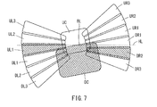
- FIG. 5 is a schematic view showing an irradiation area formed by irradiating the headlight of the headlight device shown in FIG.
- FIG. 5 is a schematic view showing an irradiation area formed by irradiating the headlight of the headlight device shown in FIG. 5 with light in front of an inclined vehicle, and shows an irradiation area in a state where the vehicle body is inclined to the left.
- FIG. 5 is a schematic view showing an irradiation area formed by irradiating the headlight of the headlight device shown in FIG. 5 with light in front of an inclined vehicle, and shows an irradiation area in a state where the vehicle body is inclined to the left.
- It is a schematic diagram which shows.
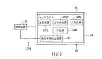
- It is a block diagram which shows the schematic structure of the modification of the headlight device shown in FIG.
- FIG. 5 shows the schematic structure of the modification of the headlight device shown in FIG.
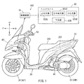
- FIG. 1 is a drawing showing a left side view of the tilting vehicle 10 and a block diagram of the headlight device 100 included in the tilting vehicle 10.
- the front direction of the inclined vehicle 10 is defined as the vehicle front direction F.
- the rear direction of the inclined vehicle 10 is defined as the vehicle rear direction B.
- the left direction of the inclined vehicle 10 is defined as the vehicle left direction L.
- the right direction of the inclined vehicle 10 is defined as the vehicle right direction R.
- the upward direction of the inclined vehicle 10 is defined as the vehicle upward direction U.
- the downward direction of the inclined vehicle 10 is defined as the vehicle downward direction D.
- the front-rear direction of the inclined vehicle 10 is defined as the vehicle front-rear direction FB.
- the left-right direction of the inclined vehicle 10 is defined as the vehicle left-right direction LR.
- the vertical direction of the inclined vehicle 10 is defined as the vehicle vertical direction UD.
- the front-rear, up-down, left-right directions of the tilting vehicle 10 are the front-rear, up-down, left-right directions as seen from the occupant seated on the seat 202 of the inclined vehicle 10.
- the vehicle body 20 can incline to the left L of the vehicle or R to the right of the vehicle.
- the vertical and horizontal directions of the vehicle body 20 do not match the vertical UD and the horizontal LR of the tilted vehicle 10.
- the vertical direction and the horizontal direction of the vehicle body 20 in the upright state coincide with the vertical direction UD and the horizontal direction LR of the inclined vehicle 10.
- the tilting vehicle 10 includes a vehicle body 20, a plurality of wheels 30, a power unit 40, and a steering wheel 50. These will be described below.
- the vehicle body 20 inclines in the vehicle left direction L when the inclined vehicle 10 turns in the vehicle left direction L, and inclines in the vehicle right direction R when the inclined vehicle 10 turns in the vehicle right direction R.
- the vehicle body 20 includes a vehicle body frame 201 and a seat 202.
- the body frame 201 supports the power unit 40.
- the power unit 40 includes an engine as a drive source, a transmission and the like. The occupant of the tilting vehicle 10 is seated on the seat 202.
- the vehicle body 20 supports a plurality of wheels 30.
- the plurality of wheels 30 are inclined to the vehicle left direction L together with the vehicle body 20 when the inclined vehicle 10 turns to the vehicle left direction L, and are inclined to the vehicle right direction R together with the vehicle body 20 when the inclined vehicle 10 turns to the vehicle right direction R.
- the plurality of wheels 30 include two front wheels 30F and one rear wheel 30R (hereinafter, simply referred to as rear wheel 30R).
- the two front wheels 30F are arranged side by side in the vehicle left-right direction LR. That is, the two front wheels 30F are a pair of left and right wheels arranged side by side in the vehicle left-right direction LR.
- the two front wheels 30F are steered by the occupant operating the steering wheel. That is, the two front wheels 30F are a pair of left and right steering wheels.
- the two front wheels 30F are inclined to the vehicle left direction L together with the vehicle body 20 when the inclined vehicle 10 turns to the vehicle left direction L, and are inclined to the vehicle right direction R together with the vehicle body 20 when the inclined vehicle 10 turns to the vehicle right direction R.
- the lean mechanism that inclines the two front wheels 30F is, for example, a parallelogram link type lean mechanism.
- the rear wheel 30R is arranged behind the two front wheels 30F in the vehicle front-rear direction FB.
- the rear wheel 30R tilts to the left side of the vehicle L together with the vehicle body 20 when the inclined vehicle 10 turns to the left L of the vehicle, and tilts to the right R of the vehicle together with the vehicle body 20 when the inclined vehicle 10 turns to the right R of the vehicle. ..
- the rear wheel 30 rotates by transmitting the power of the power unit 40. As a result, the tilting vehicle 10 runs.
- the tilting vehicle 10 further includes a headlight device 100.
- the headlight device 100 includes a headlight 60 and a control device 70.
- the headlight 60 irradiates light in front of the inclined vehicle 10.
- the headlight 60 includes a plurality of light sources 62. Each of the plurality of light sources 62 irradiates light in front of the inclined vehicle 10.
- the headlight 60 is supported by the vehicle body 20.
- the plurality of light sources 62 includes at least one lower light source 62D, at least one upper center light source 62UC, at least one upper left light source 62UL, and at least one upper right light source 62UR.
- FIG. 1 for convenience, only one of each of the lower light source 62D, the upper center light source 62UC, the upper left light source 62UL, and the upper right light source UR is shown.
- the lower light source 62D irradiates light in front of the inclined vehicle 10 so as to form a lower irradiation area.
- the upper center light source 62UC irradiates light in front of the inclined vehicle 10 so as to form an upper center irradiation area above the lower irradiation area.
- the upper left light source 62UL irradiates light in front of the inclined vehicle 10 so as to form an upper left irradiation area to the left of the upper center irradiation area.
- the upper right light source 62UR irradiates light in front of the inclined vehicle 10 so as to form an upper right irradiation area to the right of the upper center irradiation area.
- the irradiation area is formed by irradiating the headlight 60 with light in front of the inclined vehicle 10.
- the irradiation area can be confirmed by irradiating the light of the headlight 60 toward the screen arranged in front of the inclined vehicle 10.
- the mode in which the upper center irradiation area is formed above the lower irradiation area is not particularly limited as long as the center of the upper center irradiation area is formed above the center of the lower irradiation area.
- the lower end of the upper center irradiation area may overlap with the upper end of the lower irradiation area, may be located above the upper end of the lower irradiation area, or may be located below the upper end of the lower irradiation area. You may.
- the mode in which the lower end of the upper center irradiation area overlaps the upper end of the lower irradiation area includes a mode in which at least a part of the lower end of the upper center irradiation area overlaps at least a part of the upper end of the lower irradiation area.
- the mode in which the upper left irradiation area is formed to the left of the upper center irradiation area is not particularly limited as long as the center of the upper left irradiation area is formed to the left of the center of the upper center irradiation area.
- the right edge of the upper left irradiation area may overlap with the left edge of the upper center irradiation area, may be located to the left of the left edge of the upper center irradiation area, or to the right of the left edge of the upper center irradiation area. It may be located.
- the mode in which the right end of the upper left irradiation area overlaps the left end of the upper center irradiation area includes a mode in which at least a part of the right end of the upper left irradiation area overlaps with at least a part of the left end of the upper center irradiation area.
- the mode in which the upper right irradiation area is formed to the right of the upper center irradiation area is not particularly limited as long as the center of the upper right irradiation area is formed to the right of the center of the upper center irradiation area.
- the left edge of the upper right irradiation area may overlap with the right edge of the upper center irradiation area, may be located to the right of the right edge of the upper center irradiation area, or to the left of the right edge of the upper center irradiation area. It may be located.
- the mode in which the left end of the upper right irradiation area overlaps the right end of the upper center irradiation area includes a mode in which at least a part of the left end of the upper right irradiation area overlaps with at least a part of the right end of the upper center irradiation area.
- the control device 70 turns off at least one of the plurality of light sources 62, or turns off the light source 62 without any operation by the occupant of the tilting vehicle 10, depending on whether an oncoming vehicle and / or a preceding vehicle is present in front of the tilting vehicle 10.
- the headlight 60 controls the irradiation of light to the front of the inclined vehicle 10.
- the oncoming vehicle is a vehicle that travels in the direction opposite to the direction in which the inclined vehicle 10 travels.
- the preceding vehicle is a vehicle that travels in the same direction as the inclined vehicle 10 travels. The preceding vehicle does not have to travel in the same traveling lane as the inclined vehicle 10.
- the tilting vehicle 10 without operation by the occupant of the tilting vehicle 10 means that at least one light source 62 out of the plurality of light sources 62 is used depending on whether or not an oncoming vehicle and / or a preceding vehicle exists in front of the tilting vehicle 10. It does not include an operation in which the occupant of the tilting vehicle 10 selects a control mode in which the light is turned off or turned on in a dimmed state.
- the control device 70 is set in the first left turn irradiation mode when the inclined vehicle 10 is turning to the left L and there is no oncoming vehicle or a preceding vehicle in front of the inclined vehicle 10.
- the headlight 60 controls the irradiation of light to the front of the inclined vehicle 10.
- the control device 70 lights at least one upper left light source 62UL so as to form an upper left irradiation area, and the inclined vehicle 10 is traveling straight and is inclined.
- Brightness of the plurality of light sources 62 so as to reduce the brightness of at least one of the upper center irradiation area, the upper right irradiation area, and the lower irradiation area as compared with the case where the oncoming vehicle and the preceding vehicle do not exist in front of the vehicle 10.
- the light source 62 corresponding to the irradiation area for reducing the brightness is turned off or turned on in a dimmed state.
- the control device 70 is in the second left turn irradiation mode when the inclined vehicle 10 is turning to the left L and when an oncoming vehicle and a preceding vehicle are present in front of the inclined vehicle 10.
- the headlight 60 controls the irradiation of light to the front of the inclined vehicle 10.
- the control device 70 is compared with the case where the tilting vehicle 10 is turning to the left and there is no oncoming vehicle and the preceding vehicle in front of the tilting vehicle 10.
- At least one upper left light source 62L is turned on so as to maintain the state of forming at least the upper left irradiation area.
- the control device 70 lights at least one upper-left light source 62UL so as to maintain the state of forming the upper-left irradiation area as compared with the first left-turning irradiation mode.
- a state in which the light source 62 corresponding to the irradiation area for reducing the brightness among the plurality of light sources 62 is turned off or dimmed so as to reduce the brightness of at least one of the upper center irradiation area, the upper right irradiation area, and the lower irradiation area. It may be lit with.
- the control device 70 maintains the brightness of each of the upper left irradiation area, the upper center irradiation area, the upper right irradiation area, and the lower irradiation area in the second left turning irradiation mode as compared with the first left turning irradiation mode.
- each state of the plurality of light sources 62 may be maintained.
- the control device 70 is set to the first right turn irradiation mode when the inclined vehicle 10 is turning to the right R and there is no oncoming vehicle or a preceding vehicle in front of the inclined vehicle 10.
- the headlight 60 controls the irradiation of light to the front of the inclined vehicle 10.
- the control device 70 lights at least one upper right light source 62UR so as to form an upper right irradiation area, and the inclined vehicle 10 is traveling straight ahead.
- the brightness of at least one of the upper center irradiation area, the upper left irradiation area, and the lower irradiation area is reduced as compared with the case where the oncoming vehicle and the preceding vehicle are not present in front of the inclined vehicle 10.
- the light source 62 corresponding to the irradiation area that reduces the brightness is turned off or turned on in a dimmed state.
- the control device 70 is set to the second right turn irradiation mode when the inclined vehicle 10 is turning to the right R and when an oncoming vehicle and a preceding vehicle are present in front of the inclined vehicle 10.
- the headlight 60 controls the irradiation of light to the front of the inclined vehicle.
- the control device 70 is compared with the case where the tilting vehicle 10 is turning to the right R and there is no oncoming vehicle and the preceding vehicle in front of the tilting vehicle 10. Then, at least one upper right light source 62UR is turned on so as to maintain the state of forming at least the upper right irradiation area.
- the control device 70 lights at least one upper right light source 62UR in the second right turning irradiation mode so as to maintain the state of forming the upper right irradiation area as compared with the first right turning irradiation mode.
- the light source 62 corresponding to the irradiation area for reducing the brightness among the plurality of light sources 62 is turned off or dimmed so as to reduce the brightness of at least one of the upper center irradiation area, the upper left irradiation area, and the lower irradiation area. It may be lit in the state of being turned on.
- the control device 70 maintains the brightness of each of the upper left irradiation area, the upper center irradiation area, the upper right irradiation area, and the lower irradiation area in the second right turning irradiation mode as compared with the first right turning irradiation mode. As such, each state of the plurality of light sources 62 may be maintained.
- At least one brightness of the upper center irradiation area, the upper right irradiation area, and the lower irradiation area is used to reduce the brightness of at least one of the upper center irradiation area, the upper right irradiation area, and the lower irradiation area.
- a mode of partially reducing the swelling is included.
- At least one brightness of the upper center irradiation area, the upper left irradiation area, and the lower irradiation area is used to reduce the brightness of at least one of the upper center irradiation area, the upper left irradiation area, and the lower irradiation area.
- a mode of partially reducing the swelling is included.
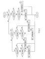
- FIG. 2 is a flowchart showing the irradiation mode switching control executed by the control device 70.
- step S11 the control device 70 determines whether or not the tilting vehicle 10 is traveling straight.
- step S11 When the tilting vehicle 10 is traveling straight (step S11: YES), the control device 70 determines in step S12 whether or not an oncoming vehicle exists in front of the tilting vehicle 10.
- step S12 When there is no oncoming vehicle in front of the inclined vehicle 10 (step S12: NO), the control device 70 determines in step S13 whether or not there is a preceding vehicle in front of the inclined vehicle 10.
- the control device 70 controls the irradiation of light by the headlight 60 so as to perform irradiation in the first straight irradiation mode in step S14. To do. In the first straight irradiation mode, for example, the lower light source 62D, the upper center light source 62UC, the upper left light source 62UL, and the upper right light source 62UR are turned on. After that, the control device 70 ends the irradiation mode switching control.
- step S12 When an oncoming vehicle is present in front of the inclined vehicle 10 (step S12: YES), the control device 70 controls the irradiation of light by the headlight 60 so as to perform irradiation in the second straight irradiation mode in step S15. To do. In the second straight irradiation mode, for example, the lower light source 62D is turned on. After that, the control device 70 ends the irradiation mode switching control.
- step S13 When the preceding vehicle exists in front of the inclined vehicle 10 (step S13: YES), the control device 70 executes the processes after step S15.
- step S11: NO the control device 70 determines in step S16 whether or not the tilting vehicle 10 is turning to the left L.
- step S16 When the tilting vehicle 10 is turning to the left L (step S16: YES), the control device 70 determines in step S17 whether or not an oncoming vehicle exists in front of the tilting vehicle 10.
- step S17 NO
- the control device 70 determines in step S18 whether or not there is a preceding vehicle in front of the inclined vehicle 10.
- step S18 NO
- the control device 70 irradiates the light by the headlight 60 so as to irradiate in the first left turn irradiation mode in step S19.
- the control device 70 ends the irradiation mode switching control.
- step S17 When an oncoming vehicle is present in front of the inclined vehicle 10 (step S17: YES), the control device 70 irradiates the light by the headlight 60 so as to irradiate in the second left turning irradiation mode in step S20. Control. In the second left-handed turning irradiation mode, for example, each of the lower light source 62D, the upper center light source 62UC, and the upper left light source 62UL is turned on. After that, the control device 70 ends the irradiation mode switching control.
- step S18 When the preceding vehicle exists in front of the inclined vehicle 10 (step S18: YES), the control device 70 executes the processes after step S20.
- step S16 NO
- the control device 70 determines in step S21 whether or not an oncoming vehicle exists in front of the tilting vehicle 10.
- step S21 When there is no oncoming vehicle in front of the inclined vehicle 10 (step S21: NO), the control device 70 determines in step S22 whether or not there is a preceding vehicle in front of the inclined vehicle 10.
- step S22 NO
- the control device 70 irradiates the light by the headlight 60 so as to irradiate in the first right turning irradiation mode in step S23.
- the first right-handed turning irradiation mode for example, the lower light source 62D, the upper center light source 62UC, and the upper right light source 62UR are turned on.
- the control device 70 ends the irradiation mode switching control.
- step S21 When an oncoming vehicle is present in front of the inclined vehicle 10 (step S21: YES), the control device 70 irradiates the light by the headlight 60 so as to irradiate in the second right turning irradiation mode in step S24. To control. In the second right-handed turning irradiation mode, for example, the lower light source 62D, the upper center light source 62UC, and the upper right light source 62UR are turned on. After that, the control device 70 ends the irradiation mode switching control.
- the second right-handed turning irradiation mode for example, the lower light source 62D, the upper center light source 62UC, and the upper right light source 62UR are turned on.
- step S22 When the preceding vehicle exists in front of the inclined vehicle 10 (step S22: YES), the control device 70 executes the processes after step S24.
- the convenience of the headlight device 100 included in the tilting vehicle 10 can be enhanced. Specifically, it is as follows.
- the headlight device 100 covers the upper left irradiation area regardless of whether or not an oncoming vehicle and / or a preceding vehicle is present in front of the tilting vehicle 10.
- the upper left irradiation area is formed in an area seen by the occupant of the inclined vehicle 10 when the inclined vehicle 10 is turning to the left L.
- at least one upper left light source 62UL is lit so as to form an upper left irradiation area, so that the occupant of the inclined vehicle 10 when the inclined vehicle 10 is turning to the left L Illuminate in the same direction as the line of sight. Therefore, the headlight device 100 can widen the field of view of the occupant of the tilting vehicle 10 when the tilting vehicle 10 is turning to the left L.
- the headlight device 100 is on the upper right regardless of whether or not an oncoming vehicle and / or a preceding vehicle is present in front of the tilting vehicle 10.
- Form an irradiation area is formed in an area seen by the occupant of the inclined vehicle 10 when the inclined vehicle 10 is turning to the right.
- at least one upper right light source 62UR is lit so as to form an upper right irradiation area, so that the line of sight of the occupant of the inclined vehicle 10 when the inclined vehicle 10 is turning to the right. Illuminates in the same direction as. Therefore, the headlight device 100 can widen the field of view of the occupant of the tilting vehicle 10 when the tilting vehicle 10 is turning to the right R.
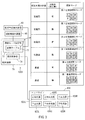
- FIG. 3 is a block diagram showing the headlight device 100A.
- the headlight device 100A is different from the headlight device 100 in that the headlight 60A is provided instead of the headlight 60.
- the headlight 60A has at least one lower center light source 62DC, at least one lower left light source 62DL and at least one lower right as at least one lower light source instead of at least one lower light source 62D.
- FIG. 3 for convenience, only one of each of the lower center light source 62DC, the lower left light source 62DL, the lower right light source 62DR, the upper center light source 62UC, the upper left light source 62UL, and the upper right light source 62UR is shown.
- At least one upper center light source 62UC irradiates light in front of the inclined vehicle 10 so as to form an upper center irradiation area UC.
- At least one upper left light source 62UL irradiates light in front of the tilting vehicle 10 so as to form an upper left irradiation area UL to the left of the upper center irradiation area UC.
- At least one upper right light source 62UR irradiates light in front of the tilting vehicle 10 so as to form an upper left irradiation area UL to the right of the upper center irradiation area UC.
- At least one lower center light source 62DC irradiates light in front of the tilting vehicle 10 so as to form a lower center irradiation area DC below the upper center irradiation area UC.
- At least one lower left light source 62DL irradiates light in front of the tilting vehicle 10 so as to form a lower left irradiation area DL below the upper left irradiation area UL and to the left of the lower center irradiation area DC.
- At least one lower right light source 62DR irradiates light in front of the tilting vehicle 10 so as to form a lower right irradiation area DR below the upper right irradiation area UR and to the right of the lower center irradiation area DC.
- the headlight device 100A is different from the headlight device 100 in that it further includes a front vehicle detection device 80 as a detection device and an inclination angle detection device 90.
- the control device 70 determines whether or not an oncoming vehicle and / or a preceding vehicle exists in front of the inclined vehicle 10 based on the signal from the front vehicle detection device 80.
- the front vehicle detection device 80 detects an oncoming vehicle and / or a preceding vehicle existing in front of the inclined vehicle 10.
- the front vehicle detection device is, for example, a photodetector capable of detecting light emitted by an oncoming vehicle and / or a preceding vehicle existing in front of the inclined vehicle 10.
- the control device 70 detects the tilt angle of the vehicle body 20 based on the signal from the tilt angle detection device 90.
- the inclination angles of the vehicle body 20 are, for example, a road surface orthogonal reference line extending in a direction orthogonal to the road surface when the vehicle body 20 is inclined with respect to a road surface in which a plurality of wheels 30 are in contact, and a vehicle body reference line extending in the vertical direction of the vehicle body 20. This is the angle that can be achieved.
- control device 70 includes an irradiation mode setting unit 72 and an irradiation control unit 74. These will be described below.
- the irradiation mode setting unit 72 sets the irradiation mode based on the signal from the inclination angle detection device 90 and the signal from the front vehicle detection device 80.
- the irradiation mode setting unit 72 uses the reference table T1 when setting the irradiation mode.
- the reference table T1 shows the relationship between the state of the inclined vehicle 10 (presence or absence of inclination of the vehicle body 20), the presence or absence of an oncoming vehicle (preceding vehicle), and the irradiation mode of the headlight 60.
- the irradiation mode of the headlight 60 set by using the reference table T1 is as follows.
- the irradiation mode setting unit 72 sets the irradiation mode as the lower center irradiation area DC, the lower left irradiation area DL, and the lower right.
- the first straight irradiation mode is set so as to form each of the irradiation area DR, the upper center irradiation area UC, the upper left irradiation area UL, and the upper right irradiation area UR.
- At least one lower center light source 62DC at least one lower left light source 62DL, at least one lower right light source 62DR, at least one upper center light source 62UC, at least one upper left light source 62UL and at least Each of the one upper right light source 62UR lights up.
- the irradiation mode setting unit 72 sets the lower center irradiation area DC, the lower left irradiation area DL, and the lower right as the irradiation mode.
- the second straight irradiation mode is set so as to form each of the irradiation area DR and not to form each of the upper center irradiation area UC, the upper left irradiation area UL, and the upper right irradiation area UR.
- each of at least one lower center light source 62DC, at least one lower left light source 62DL, and at least one lower right light source 62DR is lit, and at least one upper center light source 62UC and at least one upper Each of the left light source 62UL and at least one upper right light source 62UR is turned off.
- each of at least one upper center light source 62UC, at least one upper left light source 62UL, and at least one upper right light source 62UR may be lit in a dimmed state.
- the irradiation mode setting unit 72 has an upper center irradiation area according to the position of the oncoming vehicle and / or the preceding vehicle. At least one irradiation area of UC, upper left irradiation area UL and upper right irradiation area UR may not be formed.
- the mode in which the irradiation area is not formed includes a mode in which the light source corresponding to the irradiation area is turned off and a mode in which the light source corresponding to the irradiation area is turned on in a dimmed state.
- the irradiation mode setting unit 72 sets the lower center irradiation area DC and the lower left irradiation area as the irradiation mode.
- the first left turn irradiation mode is set so as to form each of the DL, the lower right irradiation area DR, and the upper left irradiation area UL, and not to form each of the upper center irradiation area UC and the upper right irradiation area UR.
- each of at least one lower center light source 62DC, at least one lower left light source 62DL, at least one lower right light source 62DR, and at least one upper left light source 62UL is lit, and at least one Each of the upper center light source 62UC and at least one upper right light source 62UR is turned off.
- each of at least one upper center light source 62UC and at least one upper right light source 62UR may be lit in a dimmed state.
- the irradiation area formed when the headlight 60A irradiates light in the first left turning irradiation mode is not limited to the above irradiation area.
- the irradiation area formed when the headlight 60A irradiates light in the first left-handed turning irradiation mode may include the upper left irradiation area UL.
- the irradiation mode setting unit 72 sets the lower center irradiation area DC and the upper left irradiation area as the irradiation mode.
- a second left-turn irradiation mode is set so as to form each of the ULs and not to form each of the lower left irradiation area DL, the lower right irradiation area DR, the upper center irradiation area UC, and the upper right irradiation area UR.
- each of at least one lower center light source 62DC and at least one upper left light source 62UL is lit, and at least one lower left light source 62DL, at least one lower right light source 62DR, and at least one.
- Each of the upper center light source 62UC and at least one upper right light source 62UR is turned off.
- the light sources to be turned on are not all the same in the second left-turn irradiation mode and the first left-turn irradiation mode.
- Each of at least one lower left light source 62DL, at least one lower right light source 62DR, at least one upper center light source 62UC, and at least one upper right light source 62UR may be lit in a dimmed state.
- each of at least one upper left light source 62UL and at least one lower center light source 62DC is lit so that each of the upper left irradiation area UL and the lower center irradiation area DC is formed. ..
- the irradiation area formed when the headlight 60A irradiates light in the second left turning irradiation mode is not limited to the above irradiation area.
- the irradiation area formed when the headlight 60A irradiates light in the second left turning irradiation mode is the same as the irradiation area formed when the headlight 60A irradiates light in the first left turning irradiation mode. If the irradiation area UL is included, it may be different from the irradiation area formed when the headlight 60A irradiates light in the first left turning irradiation mode.
- the irradiation mode setting unit 72 sets the lower center irradiation area DC and the lower left irradiation area as the irradiation mode.
- the first right turning irradiation mode is set so as to form each of the DL, the lower right irradiation area DR, and the upper right irradiation area UR, and not to form each of the upper center irradiation area UC and the upper left irradiation area UL.
- each of at least one lower center light source 62DC, at least one lower left light source 62DL, at least one lower right light source 62DR, and at least one upper right light source 62UR is lit, and at least one.
- Each of the upper center light source 62UC and at least one upper left light source 62UL is turned off.
- Each of at least one upper center light source 62UC and at least one upper left light source 62UL may be lit in a dimmed state.
- the irradiation area formed when the headlight 60A irradiates light in the first right-handed turning irradiation mode is not limited to the above irradiation area.
- the irradiation area formed when the headlight 60A irradiates light in the first right-handed turning irradiation mode may include the upper right irradiation area UR.
- the irradiation mode setting unit 72 sets the lower center irradiation area DC and the upper right irradiation area as the irradiation mode.
- a second right-turn irradiation mode is set so as to form each of the URs and not to form each of the lower left irradiation area DL, the lower right irradiation area DR, the upper center irradiation area UC, and the upper left irradiation area UL.
- each of at least one lower center light source 62DC and at least one upper right light source 62UR is lit, and at least one lower left light source 62DL, at least one lower right light source 62DR, and at least 1
- Each of the upper center light source 62UC and at least one upper left light source 62UL is turned off.
- the light sources to be turned on are not all the same.
- Each of at least one lower left light source 62DL, at least one lower right light source 62DR, at least one upper center light source 62UC, and at least one upper left light source 62UL may be lit in a dimmed state.
- each of at least one upper right light source 62UR and at least one lower center light source 62DC is lit so that each of the upper right irradiation area UR and the lower center irradiation area DC is formed. To do.
- the irradiation area formed when the headlight 60A irradiates light in the second right-handed turning irradiation mode is not limited to the above irradiation area.
- the irradiation area formed when the headlight 60A irradiates light in the second right-handed turning irradiation mode is the same as the irradiation area formed when the headlight 60A irradiates light in the first right-handed turning irradiation mode. If the upper right irradiation area UR is included in, the irradiation area may be different from the irradiation area formed when the headlight 60A irradiates light in the first right turning irradiation mode.
- the irradiation control unit 74 controls the lighting of each of the plurality of light sources 62 based on the irradiation mode set by the irradiation mode setting unit 72. That is, the irradiation control unit 74 switches the irradiation area of the headlight 60 based on the irradiation mode set by the irradiation mode setting unit 72.
- the irradiation mode switching control executed by the control device 70 of the headlight device 100A is the same as the irradiation mode switching control shown in FIG. 2, the description thereof will be omitted.
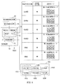
- FIG. 4 is a block diagram showing the headlight device 100A1.
- the headlight device 100A1 is different from the headlight device 100A in that the irradiation mode setting unit 72 uses the reference table T2 instead of the reference table T1 when setting the irradiation mode of the headlight 60A.
- the reference table T2 shows the relationship between the state of the inclined vehicle 10 (presence or absence of inclination of the vehicle body 20), the presence or absence of an oncoming vehicle (preceding vehicle), and the irradiation mode of the headlight 60A.
- the irradiation mode of the headlight 60A set by using the reference table T2 is as follows.
- the irradiation mode setting unit 72 sets the irradiation mode as the lower center irradiation area DC, the lower left irradiation area DL, and the lower right.
- the first straight irradiation mode is set so as to form each of the irradiation area DR, the upper center irradiation area UC, the upper left irradiation area UL, and the upper right irradiation area UR.
- At least one lower center light source 62DC at least one lower left light source 62DL, at least one lower right light source 62DR, at least one upper center light source 62UC, at least one upper left light source 62UL and at least Each of the one upper right light source 62UR lights up.
- the irradiation mode setting unit 72 sets the lower center irradiation area DC, the lower left irradiation area DL, and the lower right as the irradiation mode.
- the second straight irradiation mode is set so as to form each of the irradiation area DR and not to form each of the upper center irradiation area UC, the upper left irradiation area UL, and the upper right irradiation area UR.
- each of at least one lower center light source 62DC, at least one lower left light source 62DL, and at least one lower right light source 62DR is lit, and at least one upper center light source 62UC and at least one upper Each of the left light source 62UL and at least one upper right light source 62UR is turned off.
- each of at least one upper center light source 62UC, at least one upper left light source 62UL, and at least one upper right light source 62UR may be lit in a dimmed state.
- the irradiation mode setting unit 72 has an upper center irradiation area according to the position of the oncoming vehicle and / or the preceding vehicle. At least one irradiation area of UC, upper left irradiation area UL and upper right irradiation area UR may not be formed.
- the mode in which the irradiation area is not formed includes a mode in which the light source corresponding to the irradiation area is turned off and a mode in which the light source corresponding to the irradiation area is turned on in a dimmed state.
- the irradiation mode setting unit 72 sets the lower center irradiation area DC and the lower left irradiation area as the irradiation mode.
- the first left turn irradiation mode is set so as to form each of the DL, the lower right irradiation area DR, and the upper left irradiation area UL, and not to form each of the upper center irradiation area UC and the upper right irradiation area UR.
- each of at least one lower center light source 62DC, at least one lower left light source 62DL, at least one lower right light source 62DR, and at least one upper left light source 62UL is lit, and at least one Each of the upper center light source 62UC and at least one upper right light source 62UR is turned off.
- each of at least one upper center light source 62UC and at least one upper right light source 62UR may be lit in a dimmed state.
- the irradiation area formed when the headlight 60A irradiates light in the first left turning irradiation mode is not limited to the above irradiation area.
- the irradiation area formed when the headlight 60A irradiates light in the first left-handed turning irradiation mode may include the upper left irradiation area UL.
- the irradiation mode setting unit 72 sets the lower center irradiation area DC and the lower left irradiation area as the irradiation mode.
- a second left-turn irradiation mode is set so as to form each of the DL, the lower right irradiation area DR, and the upper left irradiation area UL, and not to form each of the upper center irradiation area UC and the upper right irradiation area UR.
- each of at least one lower center light source 62DC, at least one lower left light source 62DL, at least one lower right light source 62DR, and at least one upper left light source 62UL is lit, and at least one Each of the upper center light source 62UC and at least one upper right light source 62UR is turned off.
- the same light source is turned on in the second left-turn irradiation mode and the first left-turn irradiation mode.
- each of at least one upper center light source 62UC and at least one upper right light source 62UR may be lit in a dimmed state.
- At least one lower center light source 62DC in the second left swivel irradiation mode, at least one lower center light source 62DC, so that each of the lower center irradiation area DC, the lower left irradiation area DL, the lower right irradiation area DR, and the upper left irradiation area UL is formed.
- Each of at least one lower left light source 62DL, at least one lower right light source 62DR, and at least one upper left light source 62DL is lit.
- the irradiation area formed when the headlight 60A irradiates light in the second left turning irradiation mode is not limited to the above irradiation area.
- the irradiation area formed when the headlight 60A irradiates light in the second left turning irradiation mode is the same as the irradiation area formed when the headlight 60A irradiates light in the first left turning irradiation mode.
- the irradiation area UL is included, it may be the same as the irradiation area formed when the headlight 60A irradiates light in the first left turning irradiation mode.
- the irradiation mode setting unit 72 sets the lower center irradiation area DC and the lower left irradiation area as the irradiation mode.
- the first right turning irradiation mode is set so as to form each of the DL, the lower right irradiation area DR, and the upper right irradiation area UR, and not to form each of the upper center irradiation area UC and the upper left irradiation area UL.
- each of at least one lower center light source 62DC, at least one lower left light source 62DL, at least one lower right light source 62DR, and at least one upper right light source 62UR is lit, and at least one.
- Each of the upper center light source 62UC and at least one upper left light source 62UL is turned off.
- Each of at least one upper center light source 62UC and at least one upper left light source 62UL may be lit in a dimmed state.
- the irradiation area formed when the headlight 60A irradiates light in the first right-handed turning irradiation mode is not limited to the above irradiation area.
- the irradiation area formed when the headlight 60A irradiates light in the first right-handed turning irradiation mode may include the upper right irradiation area UR.
- the irradiation mode setting unit 72 sets the lower center irradiation area DC and the lower left irradiation area as the irradiation mode.
- a second right-turning irradiation mode is set so as to form each of the DL, the lower right irradiation area DR, and the upper right irradiation area UR, and not to form each of the upper center irradiation area UC and the upper left irradiation area UL.
- each of at least one lower center light source 62DC, at least one lower left light source 62DL, at least one lower right light source 62DR, and at least one upper right light source 62UR is lit, and at least one.
- Each of the upper center light source 62UC and at least one upper left light source 62UL is turned off. In other words, the same light source is turned on in the second right-handed turning irradiation mode and the first right-handed turning irradiation mode.
- Each of at least one upper center light source 62UC and at least one upper left light source 62UL may be lit in a dimmed state.
- At least one lower center light source 62DC is formed so that each of the lower center irradiation area DC, the lower left irradiation area DL, the lower right irradiation area DR, and the upper right irradiation area UR is formed.
- At least one lower left light source 62DL, at least one lower right light source 62DR, and at least one upper right light source 62DR are each lit.
- the irradiation area formed when the headlight 60A irradiates light in the second right-handed turning irradiation mode is not limited to the above irradiation area.
- the irradiation area formed when the headlight 60A irradiates light in the second right-handed turning irradiation mode is the same as the irradiation area formed when the headlight 60A irradiates light in the first right-handed turning irradiation mode.
- the upper right irradiation area UR is included in, it may be the same as the irradiation area formed when the headlight 60A irradiates light in the first right turning irradiation mode.
- the irradiation mode switching control executed by the control device 70 of the headlight device 100A1 is the same as the irradiation mode switching control shown in FIG. 2, the description thereof will be omitted.
- FIG. 5 is a block diagram showing the headlight device 100A2.
- the headlight device 100A2 is different from the headlight device 100A in that the headlight 60A1 is provided instead of the headlight 60A.
- the headlight 60A1 includes a plurality of lower left light sources 62DL1, 62DL2, 62DL3 as at least one lower left light source 62DL.
- the headlight 60A1 includes a plurality of lower right light sources 62DR1, 62DR2, 62DR3 as at least one lower right light source 62DR.
- the headlight 60A1 includes a plurality of upper left light sources 62UL1, 62UL2, 62UL3 as at least one upper left light source 62UL.
- the headlight 60A1 includes a plurality of upper right light sources 62UR1, 62UR2, 62UR3 as at least one upper right light source 62UR.
- FIG. 6 is a schematic view showing an irradiation area formed by irradiating the headlight 60A1 with light in front of the inclined vehicle 10.
- the irradiation area formed by irradiating the headlight 60A1 with light in front of the inclined vehicle 10 is confirmed by, for example, irradiating the screen arranged in front of the inclined vehicle 10 with light by the headlight 60A1. be able to.
- the lower center irradiation area DC is formed by irradiating the lower center light source 62DC with light in front of the inclined vehicle 10.
- the upper center irradiation area UC formed by irradiating the front of the inclined vehicle 10 with light by the upper center light source 62UC is located above the lower center irradiation area DC.
- the lower left irradiation area DL1 formed by irradiating the lower left light source 62DL1 with light in front of the inclined vehicle 10 is located to the left of the lower center irradiation area DC.
- the lower left irradiation area DL2 formed by irradiating the lower left light source 62DL2 with light in front of the inclined vehicle 10 is located to the left of the lower center irradiation area DC and below the lower left irradiation area DL1. ..
- the lower left irradiation area DL3 formed by irradiating the lower left light source 62DL3 with light in front of the inclined vehicle 10 is located to the left of the lower center irradiation area DC and below the lower left irradiation area DL2. ..
- the lower right irradiation area DR1 formed by irradiating the lower right light source 62DR1 with light in front of the inclined vehicle 10 is located to the right of the lower center irradiation area DC.
- the lower right irradiation area DR2 formed by irradiating the lower right light source 62DL2 with light in front of the inclined vehicle 10 is located to the right of the lower center irradiation area DC and below the lower right irradiation area DR1. ..
- the lower right irradiation area DR3 formed by irradiating the lower right light source 62DR3 with light in front of the inclined vehicle 10 is located to the right of the lower center irradiation area DC and below the lower right irradiation area DR2. ..
- the upper left irradiation area UL1 formed by irradiating the upper left light source 62UL1 with light in front of the inclined vehicle 10 is located to the left of the upper center irradiation area UC.
- the upper left irradiation area UL2 formed by irradiating the upper left light source 62UL2 with light in front of the inclined vehicle 10 is located to the left of the upper center irradiation area UC and above the upper left irradiation area UL1. ..
- the upper left irradiation area UL3 formed by irradiating the upper left light source 62UL3 with light in front of the inclined vehicle 10 is located to the left of the upper center irradiation area UC and above the upper left irradiation area UL2. ..
- the upper right irradiation area UR1 formed by irradiating the upper right light source 62UR1 with light in front of the inclined vehicle 10 is located to the right of the upper center irradiation area UC.
- the upper right irradiation area UR2 formed by irradiating the upper right light source 62UR2 with light in front of the inclined vehicle 10 is located to the right of the upper center irradiation area UC and above the upper right irradiation area UR1. ..
- the upper right irradiation area UR3 formed by irradiating the upper right light source 62UR3 with light in front of the inclined vehicle 10 is located to the right of the upper center irradiation area UC and above the upper right irradiation area UR2. ..
- the control device 70 further controls the irradiation of light to the front of the tilting vehicle 10 by the headlight 60 in the low beam irradiation mode.
- the low beam irradiation mode at least one lower center light source 62DC is turned on so that the lower center irradiation area DC is formed, and at least one upper center light source 62UC is turned off so that the upper center irradiation area UC is not formed.
- the lower left irradiation area DL1 is hatched to show that the lower left irradiation area DL1 is formed as a left low beam irradiation area.
- the lower right irradiation area DR1 is hatched to show that the lower right irradiation area DR1 is formed as a right low beam irradiation area.
- the horizontal reference line HL is a boundary line BL formed at the upper end of the lower center irradiation area DC in a state where the vehicle body 20 is upright and extends in the left-right direction of the inclined vehicle 10, to the left L and right of the inclined vehicle 10. It is a straight line extending in each of the directions R.
- the irradiation areas DR1, DR2, DR3 and the upper right irradiation area UR1, UR2, or UR3) change according to the inclination angle of the vehicle body 20.
- the left low beam irradiation area and the right low beam irradiation area when the vehicle body 20 is tilted to the left L will be described with reference to FIG. 7.
- the upper left irradiation area UL1 is hatched to show that the upper left irradiation area UL1 is formed as a left low beam irradiation area.
- the lower right irradiation area DR2 is hatched to show that the lower right irradiation area DR2 is formed as a right low beam irradiation area.
- the range in which the light of the headlight 60A1 is irradiated can be expanded in the low beam irradiation mode.
- FIG. 8 is a block diagram showing a schematic configuration of the headlight device 100B.
- the headlight 60 further includes a housing 64.
- the housing 64 accommodates the front vehicle detection device 80 as a detection device.
- the housing 64 includes a housing body 641 and an outer lens 642.
- the outer lens 642 is attached to the housing body 641 and is arranged in front of the plurality of light sources 62.
- the outer lens 642 is, for example, circular when viewed in the rear direction of the tilting vehicle 10.
- FIG. 9 is a block diagram showing a schematic configuration of the headlight device 100B1.
- the housing 64 houses the control device 70.
- Such gist is an equal element, modification, deletion, combination (eg, combination of features across embodiments and variants), improvement, modification that can be recognized by those skilled in the art based on the embodiments disclosed herein. Including.
- the limitations of the claims should be broadly construed based on the terms used in the claims and are limited to the embodiments and variations described herein or in the process of the present application. Should not be done.
- Such embodiments and variations should be construed as non-exclusive.
- the terms "preferably” and “good” are non-exclusive and are “preferable but not limited to” and “good but not limited thereto”. It means "no".
- the tilting vehicle 10 is provided with a pair of left and right steering wheels (two front wheels 30F).
- the tilting vehicle of the present invention may be a tilting vehicle having one steering wheel (that is, one front wheel).
- the power source of the tilting vehicle 10 is an engine.
- the power source of the tilting vehicle of the present invention may be an electric motor, or an engine and an electric motor.
- Inclined vehicle 20 Body 201 Body frame 202 Seat 60 Headlight 62 Light source 62D Lower light source 62UC Upper center light source 62UL Upper left light source 62UR Upper right light source 64 Housing 641 Housing 641 Outer lens 70 Control device 80 Front vehicle detection device (detection device) ) 100 headlight device
Landscapes
- Engineering & Computer Science (AREA)
- Mechanical Engineering (AREA)
- General Engineering & Computer Science (AREA)
- Lighting Device Outwards From Vehicle And Optical Signal (AREA)
Abstract
傾斜車両の前に対向車及び/又は先行車が存在するか否かに応じて照射エリアを傾斜車両の乗員による操作なしで切り替えるヘッドライト装置の利便性を高める。制御装置は、傾斜車両が左方向に旋回している場合であって、かつ、傾斜車両の前に対向車及び/又は先行車が存在する場合には、傾斜車両が左方向に旋回している場合であって、かつ、傾斜車両の前に対向車及び先行車が存在しない場合と比べて、少なくとも上左照射エリアを形成している状態を維持するように少なくとも1つの上左光源を点灯する。制御装置は、傾斜車両が右方向に旋回している場合であって、かつ、傾斜車両の前に対向車及び/又は先行車が存在する場合には、傾斜車両が右方向に旋回している場合であって、かつ、傾斜車両の前に対向車及び先行車が存在しない場合と比べて、少なくとも上右照射エリアを形成している状態を維持するように少なくとも1つの上右光源を点灯する。
Description
本発明は、傾斜車両に用いられるヘッドライト装置に関し、詳しくは、傾斜車両の前に対向車及び/又は先行車が存在するか否かに応じて照射エリアを傾斜車両の乗員による操作なしで切り替えるヘッドライト装置に関する。
従来、自動二輪車等の傾斜車両が知られている。傾斜車両は、車体を備える。車体は、傾斜車両が左方向に旋回するときには左方向に傾斜し、傾斜車両が右方向に旋回するときには右方向に傾斜する。
近年、傾斜車両に用いられ、傾斜車両の前に対向車及び/又は先行車が存在するか否かに応じて照射エリアを傾斜車両の乗員による操作なしで切り替えるヘッドライト装置が知られている。このようなヘッドライト装置は、国際公開第2018/168249号に開示されている。
上記公報に記載のヘッドライト装置の利便性を高めることが求められている。
本発明の目的は、傾斜車両に用いられ、傾斜車両の前に対向車及び/又は先行車が存在するか否かに応じて照射エリアを傾斜車両の乗員による操作なしで切り替えるヘッドライト装置の利便性を高めることである。
また、本発明は、上述のように利便性が高められたヘッドライト装置を備える傾斜車両を提供することも目的とする。
本願の発明者等は、傾斜車両の前に対向車及び/又は先行車が存在するか否かに応じて照射エリアを傾斜車両の乗員による操作なしで切り替えるヘッドライト装置を備える傾斜車両を走行させてみた。その結果、以下の知見を得るに至った。
本願の発明者等は、下照射エリアと、下照射エリアの上に形成される上中央照射エリアと、上中央照射エリアの左に形成される上左照射エリアと、上中央照射エリアの右に形成される上右照射エリアとを含む照射エリアを形成するヘッドライト装置を備える傾斜車両を走行させてみた。
上記ヘッドライト装置は、傾斜車両が直進している場合には、照射エリアとして、下照射エリア、上中央照射エリア、上左照射エリア及び上右照射エリアの全てを形成する。一方、傾斜車両が旋回している場合には、旋回する方向に応じて照射エリアを切り替える。
具体的には、上記ヘッドライト装置は、傾斜車両が左方向に旋回している場合には、上左照射エリアを形成するけれど、上右照射エリアを形成しない。上記ヘッドライト装置は、傾斜車両が右方向に旋回している場合には、上右照射エリアを形成するけれど、上左照射エリアを形成しない。
また、上記ヘッドライト装置は、傾斜車両が左方向に旋回している場合であって、かつ、傾斜車両の前に対向車及び/又は先行車が存在する場合には、上左照射エリアを形成しない。傾斜車両が右方向に旋回している場合であって、かつ、傾斜車両の前に対向車及び/又は先行車が存在する場合には、上右照射エリアを形成しない。
ここで、傾斜車両が左方向に旋回している場合、上左照射エリアは傾斜車両の乗員が傾斜車両の旋回中に見る領域に形成される。そのため、傾斜車両が左方向に旋回している場合に、傾斜車両の前に対向車及び/又は先行車が存在して、上左照射エリアが形成されなくなると、上左照射エリアが形成されることで見えやすくなるというメリットを失う。
また、傾斜車両が右方向に旋回している場合、上右照射エリアは傾斜車両の乗員が傾斜車両の旋回中に見る領域に形成される。そのため、傾斜車両が右方向に旋回している場合に、傾斜車両の前に対向車及び/又は先行車が存在して、上右照射エリアが形成されなくなると、上右照射エリアが形成されることで見えやすくなるというメリットを失う。
そこで、本願の発明者等は、左方向に旋回している傾斜車両の前に対向車及び/又は先行車が存在する場合に、上左照射エリアが対向車や先行車の乗員にとってどれくらい眩しいかを検討してみた。また、右方向に旋回している傾斜車両の前に対向車及び/又は先行車が存在する場合に、上右照射エリアが対向車や先行車の乗員にとってどれくらい眩しいかを検討してみた。
その結果、左方向に旋回している傾斜車両の前に対向車及び/又は先行車が存在する場合に上左照射エリアが形成されていても、対向車や先行車の乗員はそれほど眩しくないということが判った。また、右方向に旋回している傾斜車両の前に対向車及び/又は先行車が存在する場合に上右照射エリアが形成されていても、対向車や先行車の乗員はそれほど眩しくないということが判った。
このような知見は、本発明者等の検討によって初めて得られたものである。そして、本発明は、このような知見に基づいて完成されたものである。
本発明の一実施形態に係るヘッドライト装置は、左方向に旋回するときには左方向に傾斜しかつ右方向に旋回するときには右方向に傾斜する車体を備える傾斜車両に用いられる。ヘッドライト装置は、ヘッドライトと、制御装置とを備える。ヘッドライトは、複数の光源を含む。複数の光源は、それぞれ、傾斜車両の前方に光を照射する。制御装置は、傾斜車両の前に対向車及び/又は先行車が存在するか否かに応じて複数の光源のうち少なくとも1つの光源を傾斜車両の乗員による操作なしで消灯又は減光した状態で点灯することにより、ヘッドライトによる傾斜車両の前方への光の照射を制御する。
本発明の一実施形態に係るヘッドライト装置において、複数の光源は、少なくとも1つの下光源と、少なくとも1つの上中央光源と、少なくとも1つの上左光源と、少なくとも1つの上右光源とを含む。少なくとも1つの下光源は、下照射エリアを形成するように傾斜車両の前方に光を照射する。少なくとも1つの上中央光源は、下照射エリアの上に上中央照射エリアを形成するように傾斜車両の前方に光を照射する。少なくとも1つの上左光源は、上中央照射エリアの左に上左照射エリアを形成するように傾斜車両の前方に光を照射する。少なくとも1つの上右光源は、上中央照射エリアの右に上右照射エリアを形成するように傾斜車両の前方に光を照射する。
本発明の一実施形態に係るヘッドライト装置において、制御装置は、傾斜車両が左方向に旋回している場合であって、かつ、傾斜車両の前に対向車及び先行車が存在しない場合には、第1左旋回照射モードにてヘッドライトによる傾斜車両の前方への光の照射を制御する。制御装置は、第1左旋回照射モードでは、上左照射エリアを形成するように少なくとも1つの上左光源を点灯するとともに、傾斜車両が直進している場合であって、かつ、傾斜車両の前に対向車及び先行車が存在しない場合と比べて、上中央照射エリア、上右照射エリア及び下照射エリアの少なくとも1つの明るさを低下させるように、複数の光源のうち明るさを低下させる照射エリアに対応する光源を消灯又は減光した状態で点灯する。
本発明の一実施形態に係るヘッドライト装置において、制御装置は、傾斜車両が左方向に旋回している場合であって、かつ、傾斜車両の前に対向車及び/又は先行車が存在する場合には、第2左旋回照射モードにてヘッドライトによる傾斜車両の前方への光の照射を制御する。制御装置は、第2左旋回照射モードでは、傾斜車両が左方向に旋回している場合であって、かつ、傾斜車両の前に対向車及び先行車が存在しない場合と比べて、少なくとも上左照射エリアを形成している状態を維持するように少なくとも1つの上左光源を点灯する。
本発明の一実施形態に係るヘッドライト装置において、制御装置は、傾斜車両が右方向に旋回している場合であって、かつ、傾斜車両の前に対向車及び先行車が存在しない場合には、第1右旋回照射モードにてヘッドライトによる傾斜車両の前方への光の照射を制御する。制御装置は、第1右旋回照射モードでは、上右照射エリアを形成するように少なくとも1つの上右光源を点灯するとともに、傾斜車両が直進している場合であって、かつ、傾斜車両の前に対向車及び先行車が存在しない場合と比べて、上中央照射エリア、上左照射エリア及び下照射エリアの少なくとも1つの明るさを低下させるように、複数の光源のうち明るさを低下させる照射エリアに対応する光源を消灯又は減光した状態で点灯する。
本発明の一実施形態に係るヘッドライト装置において、制御装置は、傾斜車両が右方向に旋回している場合であって、かつ、傾斜車両の前に対向車及び/又は先行車が存在する場合には、第2右旋回照射モードにてヘッドライトによる傾斜車両の前方への光の照射を制御する。制御装置は、第2右旋回照射モードでは、傾斜車両が右方向に旋回している場合であって、かつ、傾斜車両の前に対向車及び先行車が存在しない場合と比べて、少なくとも上右照射エリアを形成している状態を維持するように少なくとも1つの上右光源を点灯する。
上記ヘッドライト装置においては、利便性を高めることができる。具体的には、以下のとおりである。
上記ヘッドライト装置は、傾斜車両が左方向に旋回している場合には、傾斜車両の前に対向車及び/又は先行車が存在するか否かにかかわらず、上左照射エリアを形成する。ここで、上左照射エリアは、傾斜車両が左方向に旋回しているときに、傾斜車両の乗員が見る領域に形成される。別の表現をすれば、少なくとも1つの上左光源は、上左照射エリアを形成するように点灯することで、傾斜車両が左方向に旋回しているときの傾斜車両の乗員の視線と同じ方向を照らす。そのため、上記ヘッドライト装置は、傾斜車両が左方向に旋回しているときの傾斜車両の乗員の視界を広げることができる。
同様に、上記ヘッドライト装置は、傾斜車両が右方向に旋回している場合には、傾斜車両の前に対向車及び/又は先行車が存在するか否かにかかわらず、上右照射エリアを形成する。ここで、上右照射エリアは、傾斜車両が右方向に旋回しているときに、傾斜車両の乗員が見る領域に形成される。別の表現をすれば、少なくとも1つの上右光源は、上右照射エリアを形成するように点灯することで、傾斜車両が右方向に旋回しているときの傾斜車両の乗員の視線と同じ方向を照らす。そのため、上記ヘッドライト装置は、傾斜車両が右方向に旋回しているときの傾斜車両の乗員の視界を広げることができる。
本発明の一実施形態に係るヘッドライト装置を備える傾斜車両は、例えば、少なくとも1つの前輪と、少なくとも1つの後輪とを備える。つまり、傾斜車両は、二輪車に限定されず、前輪又は後輪が左右一対の車輪で構成された三輪車であってもよいし、前輪及び後輪がそれぞれ左右一対の車輪で構成された四輪車であってもよい。
本発明の一実施形態に係るヘッドライト装置を備える傾斜車両において、車体は、車体フレームを含む。車体フレームは、複数の部品を組み合わせたフレ-ムであってもよいし、複数の部品を一体的に成形したフレ-ムであってもよい。車体フレームの材料は、アルミ、鉄などの金属であってもよいし、CFRPなどの合成樹脂であってもよいし、それらの組み合わせであってもよい。車体フレームは、傾斜車両の外観部品で構成したモノコック構造であってもよいし、その一部が傾斜車両の外観部品を兼ねるセミモノコック構造であってもよい。
本発明の一実施形態に係るヘッドライト装置において、複数の光源は、それぞれ、傾斜車両の前方に照射される光を発することができるものであれば、特に限定されない。複数の光源の各々は、例えば、発光ダイオード(LED)である。
本発明の一実施形態に係るヘッドライト装置において、下光源の数、上中央光源の数、上左光源の数及び上右光源の数は、互いに同じであってもよいし、互いに異なってもよい。下光源の数、上中央光源の数、上左光源の数及び上右光源の数のうちの少なくとも2つは、互いに同じであってもよい。
本発明の一実施形態に係るヘッドライト装置において、光源が傾斜車両の前方に光を照射する態様は、特に限定されない。光源は、傾斜車両の前方に直接光を照射してもよいし、光を反射する反射部材を介して傾斜車両の前方に光を照射してもよい。
本発明の一実施形態に係るヘッドライト装置において、制御装置は、例えば、ECU(Electric Control Unit)である。ECUは、例えば、IC(Integrated Circuit)、電子部品、回路基板等の組み合わせによって実現される。制御装置が実行する制御は、例えば、CPU(Central Processing Unit)が不揮発性のメモリに記憶されたプログラムを読み出し、当該プログラムに従って所定の処理を実行すること等によって実現される。
本発明において、対向車は、本発明の一実施形態に係るヘッドライト装置を備える傾斜車両が進む方向とは反対の方向に進む車両であれば、特に限定されない。
本発明において、先行車は、本発明の一実施形態に係るヘッドライト装置を備える傾斜車両が進む方向と同じ方向に進む車両であれば、特に限定されない。先行車は、本発明の一実施形態に係るヘッドライト装置を備える傾斜車両と同じ走行レーンを走行していなくてもよい。
本発明の一実施形態に係るヘッドライト装置において、「傾斜車両の乗員による操作なしで」とは、傾斜車両の前に対向車及び/又は先行車が存在するか否かに応じて複数の光源のうち少なくとも1つの光源を消灯(又は減光した状態で点灯)する制御モードを傾斜車両の乗員が選択する操作を含まない。
本発明の一実施形態に係るヘッドライト装置において、上中央照射エリアが下照射エリアの上に形成される態様は、上中央照射エリアの中心が下照射エリアの中心よりも上に形成されていれば、特に限定されない。上中央照射エリアの下端は、下照射エリアの上端と重なっていてもよいし、下照射エリアの上端よりも上に位置していてもよいし、下照射エリアの上端よりも下に位置していてもよい。上中央照射エリアの下端が下照射エリアの上端に重なる態様は、上中央照射エリアの下端の少なくとも一部が下照射エリアの上端の少なくとも一部に重なる態様を含む。
本発明の一実施形態に係るヘッドライト装置において、上左照射エリアが上中央照射エリアの左に形成される態様は、上左照射エリアの中心が上中央照射エリアの中心よりも左に形成されていれば、特に限定されない。上左照射エリアの右端は、上中央照射エリアの左端と重なっていてもよいし、上中央照射エリアの左端よりも左に位置していてもよいし、上中央照射エリアの左端よりも右に位置していてもよい。上左照射エリアの右端が上中央照射エリアの左端に重なる態様は、上左照射エリアの右端の少なくとも一部が上中央照射エリアの左端の少なくとも一部に重なる態様を含む。
本発明の一実施形態に係るヘッドライト装置において、上右照射エリアが上中央照射エリアの右に形成される態様は、上右照射エリアの中心が上中央照射エリアの中心よりも右に形成されていれば、特に限定されない。上右照射エリアの左端は、上中央照射エリアの右端と重なっていてもよいし、上中央照射エリアの右端よりも右に位置していてもよいし、上中央照射エリアの右端よりも左に位置していてもよい。上右照射エリアの左端が上中央照射エリアの右端に重なる態様は、上右照射エリアの左端の少なくとも一部が上中央照射エリアの右端の少なくとも一部に重なる態様を含む。
本発明の一実施形態に係るヘッドライト装置において、上中央照射エリア、上右照射エリア及び下照射エリアの少なくとも1つの明るさを低下させる態様は、上中央照射エリア、上右照射エリア及び下照射エリアの少なくとも1つの明るさを部分的に低下させる態様を含む。
本発明の一実施形態に係るヘッドライト装置において、上中央照射エリア、上左照射エリア及び下照射エリアの少なくとも1つの明るさを低下させる態様は、上中央照射エリア、上左照射エリア及び下照射エリアの少なくとも1つの明るさを部分的に低下させる態様を含む。
本発明の一実施形態に係るヘッドライト装置において、制御装置は、第2左旋回照射モードでは、第1左旋回照射モードと比べて、上左照射エリアを形成している状態を維持するように少なくとも1つの上左光源を点灯するとともに、上中央照射エリア、上右照射エリア及び下照射エリアの少なくとも1つの明るさを低下させるように、複数の光源のうち明るさを低下させる照射エリアに対応する光源を消灯又は減光した状態で点灯してもよい。
本発明の一実施形態に係るヘッドライト装置において、制御装置は、第2右旋回照射モードでは、第1右旋回照射モードと比べて、上右照射エリアを形成している状態を維持するように少なくとも1つの上右光源を点灯するとともに、上中央照射エリア、上左照射エリア及び下照射エリアの少なくとも1つの明るさを低下させるように、複数の光源のうち明るさを低下させる照射エリアに対応する光源を消灯又は減光した状態で点灯してもよい。
本発明の一実施形態に係るヘッドライト装置において、制御装置は、第2左旋回照射モードでは、第1左旋回照射モードと比べて、上左照射エリア、上中央照射エリア、上右照射エリア及び下照射エリアの各々の明るさを維持するように、複数の光源の各々の状態を維持してもよい。
本発明の一実施形態に係るヘッドライト装置において、制御装置は、第2右旋回照射モードでは、第1右旋回照射モードと比べて、上左照射エリア、上中央照射エリア、上右照射エリア及び下照射エリアの各々の明るさを維持するように、複数の光源の各々の状態を維持してもよい。
本発明の一実施形態に係るヘッドライト装置において、少なくとも1つの下光源は、少なくとも1つの下中央光源と、少なくとも1つの下左光源と、少なくとも1つの下右光源とを含んでいてもよい。少なくとも1つの下中央光源は、上中央照射エリアの下に下中央照射エリアを形成するように傾斜車両の前方に光を照射する。少なくとも1つの下左光源は、上左照射エリアの下であってかつ下中央照射エリアの左に下左照射エリアを形成するように傾斜車両の前方に光を照射する。少なくとも1つの下右光源は、上右照射エリアの下であってかつ下中央照射エリアの右に下右照射エリアを形成するように傾斜車両の前方に光を照射する。
本発明の一実施形態に係るヘッドライト装置において、制御装置は、第2左旋回照射モードでは、上左照射エリアと下中央照射エリアの各々を形成するように、少なくとも1つの上左光源と少なくとも1つの下中央光源の各々を点灯してもよい。
本発明の一実施形態に係るヘッドライト装置において、制御装置は、第2右旋回照射モードでは、上右照射エリアと下中央照射エリアの各々を形成するように、少なくとも1つの上右光源と少なくとも1つの下中央光源の各々を点灯してもよい。
本発明の一実施形態に係るヘッドライト装置において、制御装置は、第2左旋回照射モードでは、下中央照射エリア、下左照射エリア、下右照射エリア及び上左照射エリアの各々を形成するように、少なくとも1つの下中央光源、少なくとも1つの左下光源、少なくとも1つの右下光源及び少なくとも1つの上左光源の各々を点灯してもよい。
本発明の一実施形態に係るヘッドライト装置において、制御装置は、第2右旋回照射モードでは、下中央照射エリア、下左照射エリア、下右照射エリア及び上右照射エリアの各々を形成するように、少なくとも1つの下中央光源、少なくとも1つの左下光源、少なくとも1つの右下光源及び少なくとも1つの上右光源の各々を点灯してもよい。
本発明の一実施形態に係るヘッドライト装置において、少なくとも1つの下左光源は、複数の下左光源を含んでいてもよい。少なくとも1つの下右光源は、複数の下右光源を含んでいてもよい。少なくとも1つの上左光源は、複数の上左光源を含んでいてもよい。少なくとも1つの上右光源は、複数の上右光源を含んでいてもよい。
本発明の一実施形態に係るヘッドライト装置において、制御装置は、さらに、ロービーム照射モードにてヘッドライトによる傾斜車両の前方への光の照射を制御してもよい。ロービーム照射モードでは、下中央照射エリアを形成するように少なくとも1つの下中央光源を点灯し、かつ、上中央照射エリアを形成しないように少なくとも1つの上中央光源を消灯する。また、ロービーム照射モードでは、水平基準線の下に位置しかつ水平基準線に最も近い左ロービーム照射エリアを車体の傾斜角に応じて形成するように、複数の上左光源と複数の下左光源からなる複数の左光源のなかから選択した左光源を点灯してもよい。また、ロービーム照射モードでは、水平基準線の下に位置しかつ水平基準線に最も近い右ロービーム照射エリアを車体の傾斜角に応じて形成するように、複数の上右光源と複数の下右光源からなる複数の右光源のなかから選択した右光源を点灯してもよい。なお、水平基準線は、車体が直立している状態で下中央照射エリアの上端に形成されて傾斜車両の左右方向に延びる境界線を傾斜車両の左方向及び右方向の各々に延長した直線である。
本発明の一実施形態に係るヘッドライト装置において、「水平基準線の下に位置しかつ水平基準線に最も近い左ロービーム照射エリア」とは、下中央照射エリアの左に形成され、各々の中心が水平基準線よりも下に位置する複数の左照射エリアのうち、中心が最も水平基準線に近い左照射エリアのことをいう。左ロービーム照射エリアとして形成されている左照射エリアであっても、車体の傾斜角が変化することにより、その中心が水平基準線に重なる又は水平基準線よりも上に移動すると、左ロービーム照射エリアとして形成されなくなる。
本発明の一実施形態に係るヘッドライト装置において、「水平基準線の下に位置しかつ水平基準線に最も近い右ロービーム照射エリア」とは、下中央照射エリアの右に形成され、各々の中心が水平基準線よりも下に位置する複数の右照射エリアのうち、中心が最も水平基準線に近い右照射エリアのことをいう。右ロービーム照射エリアとして形成されている右照射エリアであっても、車体の傾斜角が変化することにより、その中心が水平基準線に重なる又は水平基準線よりも上に移動すると、右ロービーム照射エリアとして形成されなくなる。
本発明の一実施形態に係るヘッドライト装置は、検出装置をさらに備えていてもよい。検出装置は、傾斜車両の前に存在する対向車及び/又は先行車を検出する。
本発明の一実施形態に係るヘッドライト装置において、検出装置は、対向車及び/又は先行車が発する光を検出するものであってもよい。
本発明の一実施形態に係るヘッドライト装置において、ヘッドライトは、複数の光源を収容する筐体をさらに含んでいてもよい。筐体は、検出装置を収容する。
本発明の一実施形態に係るヘッドライト装置において、筐体は、筐体本体と、アウタレンズとを含んでいてもよい。アウタレンズは、筐体本体に取り付けられて、複数の光源の前に配置される。傾斜車両の後方向に見て、アウタレンズは円形である。
本発明の一実施形態に係るヘッドライト装置において、筐体は、制御装置を収容してもよい。
本発明の一実施形態に係る傾斜車両は、左方向に旋回するときには左方向に傾斜しかつ右方向に旋回するときには右方向に傾斜する車体と、本発明の一実施形態に係るヘッドライト装置とを備える。
この発明の上述の目的及びその他の目的、特徴、局面及び利点は、添付図面に関連して行われる以下のこの発明の実施形態の詳細な説明から一層明らかとなろう。
本明細書にて使用される場合、用語「及び/又は(and/or)」は1つの、又は複数の関連した列挙されたアイテム(items)のあらゆる又は全ての組み合わせを含む。
本明細書中で使用される場合、用語「含む、備える(including)」、「含む、備える(comprising)」又は「有する(having)」及びその変形の使用は、記載された特徴、工程、操作、要素、成分及び/又はそれらの等価物の存在を特定するが、ステップ、動作、要素、コンポーネント、及び/又はそれらのグループのうちの1つ又は複数を含むことができる。
他に定義されない限り、本明細書で使用される全ての用語(技術用語及び科学用語を含む)は、本発明が属する当業者によって一般的に理解されるのと同じ意味を有する。
一般的に使用される辞書に定義された用語のような用語は、関連する技術及び本開示の文脈における意味と一致する意味を有すると解釈されるべきであり、本明細書で明示的に定義されていない限り、理想的又は過度に形式的な意味で解釈されることはない。
本発明の説明においては、技術及び工程の数が開示されていると理解される。これらの各々は個別の利益を有し、それぞれは、他の開示された技術の1つ以上、又は、場合によっては全てと共に使用することもできる。従って、明確にするために、この説明は、不要に個々のステップの可能な組み合わせの全てを繰り返すことを控える。それにもかかわらず、明細書及び特許請求の範囲は、そのような組み合わせが全て本発明及び特許請求項の範囲内にあることを理解して読まれるべきである。
以下の説明では、説明の目的で、本発明の完全な理解を提供するために多数の具体的な詳細を述べる。しかしながら、当業者には、これらの特定の詳細なしに本発明を実施できることが明らかである。本開示は、本発明の例示として考慮されるべきであり、本発明を以下の図面又は説明によって示される特定の実施形態に限定することを意図するものではない。
本発明によれば、傾斜車両に用いられ、傾斜車両の前に対向車及び/又は先行車が存在するか否かに応じて照射エリアを傾斜車両の乗員による操作なしで切り替えるヘッドライト装置の利便性を高めることができる。
また、本発明によれば、上述のように利便性が高められたヘッドライト装置を備える傾斜車両を提供することができる。
以下、図面を参照しながら、本発明の実施の形態による傾斜車両の詳細について説明する。なお、以下に説明する実施の形態は、あくまでも一例である。本発明は、以下に説明する実施の形態によって、何等、限定的に解釈されるものではない。
図1を参照しながら、本発明の実施の形態による傾斜車両10について説明する。図1は、傾斜車両10の左側面図と傾斜車両10が備えるヘッドライト装置100のブロック図とを併せて示す図面である。
本明細書では、傾斜車両10における各種の方向を、以下のように定義する。
傾斜車両10の前方向を車両前方向Fと定義する。傾斜車両10の後方向を車両後方向Bと定義する。傾斜車両10の左方向を車両左方向Lと定義する。傾斜車両10の右方向を車両右方向Rと定義する。傾斜車両10の上方向を車両上方向Uと定義する。傾斜車両10の下方向を車両下方向Dと定義する。傾斜車両10の前後方向を車両前後方向FBと定義する。傾斜車両10の左右方向を車両左右方向LRと定義する。傾斜車両10の上下方向を車両上下方向UDと定義する。なお、傾斜車両10の前後上下左右は、傾斜車両10のシート202に着座した乗員から見た前後上下左右である。
傾斜車両10では、車体20が車両左方向L又は車両右方向Rに傾斜できる。車体20が車両左方向L又は車両右方向Rに傾斜している場合、車体20の上下方向及び左右方向は、傾斜車両10の上下方向UD及び左右方向LRと一致しない。一方、直立状態の車体20の上下方向及び左右方向は、傾斜車両10の上下方向UD及び左右方向LRと一致する。
図1を参照して、傾斜車両10は、車体20と、複数の車輪30と、パワーユニット40と、ハンドル50とを備える。以下、これらについて説明する。
車体20は、傾斜車両10が車両左方向Lに旋回するときに車両左方向Lに傾斜し、傾斜車両10が車両右方向Rに旋回するときに車両右方向Rに傾斜する。車体20は、車体フレーム201と、シート202とを含む。車体フレーム201は、パワーユニット40を支持する。パワーユニット40は、駆動源としてのエンジンと、変速機等を含む。シート202には、傾斜車両10の乗員が着座する。
車体20は、複数の車輪30を支持する。複数の車輪30は、傾斜車両10が車両左方向Lに旋回するときには車体20とともに車両左方向Lに傾斜し、傾斜車両10が車両右方向Rに旋回するときには車体20とともに車両右方向Rに傾斜する。複数の車輪30は、2つの前輪30Fと、1つの後輪30R(以下、単に後輪30Rと称する)とを含む。
2つの前輪30Fは、車両左右方向LRに並んで配置される。つまり、2つの前輪30Fは、車両左右方向LRに並んで配置される左右一対の車輪である。2つの前輪30Fは、乗員がハンドルを操作することにより操舵される。つまり、2つの前輪30Fは、左右一対の操舵輪である。2つの前輪30Fは、傾斜車両10が車両左方向Lに旋回するときには車体20とともに車両左方向Lに傾斜し、傾斜車両10が車両右方向Rに旋回するときには車体20とともに車両右方向Rに傾斜する。2つの前輪30Fを傾斜させるリーン機構は、例えば、パラレログラムリンク方式のリーン機構である。
後輪30Rは、車両前後方向FBにおいて2つの前輪30Fよりも後に配置される。後輪30Rは、傾斜車両10が車両左方向Lに旋回するときには車体20とともに車両左方向Lに傾斜し、傾斜車両10が車両右方向Rに旋回するときには車体20とともに車両右方向Rに傾斜する。後輪30は、パワーユニット40の動力が伝達されることで回転する。これにより、傾斜車両10が走行する。
傾斜車両10は、ヘッドライト装置100をさらに備える。ヘッドライト装置100は、ヘッドライト60と、制御装置70とを含む。
ヘッドライト60は、傾斜車両10の前方に光を照射する。ヘッドライト60は、複数の光源62を含む。複数の光源62の各々は、傾斜車両10の前方に光を照射する。なお、ヘッドライト60は、車体20に支持される。
複数の光源62は、少なくとも1つの下光源62Dと、少なくとも1つの上中央光源62UCと、少なくとも1つの上左光源62ULと、少なくとも1つの上右光源62URとを含む。なお、図1では、便宜上、下光源62D、上中央光源62UC、上左光源62UL及び上右光源URの各々を1つだけ示している。
下光源62Dは、下照射エリアを形成するように傾斜車両10の前方に光を照射する。上中央光源62UCは、下照射エリアの上に上中央照射エリアを形成するように傾斜車両10の前方に光を照射する。上左光源62ULは、上中央照射エリアの左に上左照射エリアを形成するように傾斜車両10の前方に光を照射する。上右光源62URは、上中央照射エリアの右に上右照射エリアを形成するように傾斜車両10の前方に光を照射する。
ここで、照射エリアは、ヘッドライト60が傾斜車両10の前方に光を照射することで形成される。なお、照射エリアは、傾斜車両10の前方に配置されたスクリーンに向かってヘッドライト60の光を照射することで確認することができる。
上中央照射エリアが下照射エリアの上に形成される態様は、上中央照射エリアの中心が下照射エリアの中心よりも上に形成されていれば、特に限定されない。上中央照射エリアの下端は、下照射エリアの上端と重なっていてもよいし、下照射エリアの上端よりも上に位置していてもよいし、下照射エリアの上端よりも下に位置していてもよい。上中央照射エリアの下端が下照射エリアの上端に重なる態様は、上中央照射エリアの下端の少なくとも一部が下照射エリアの上端の少なくとも一部に重なる態様を含む。
上左照射エリアが上中央照射エリアの左に形成される態様は、上左照射エリアの中心が上中央照射エリアの中心よりも左に形成されていれば、特に限定されない。上左照射エリアの右端は、上中央照射エリアの左端と重なっていてもよいし、上中央照射エリアの左端よりも左に位置していてもよいし、上中央照射エリアの左端よりも右に位置していてもよい。上左照射エリアの右端が上中央照射エリアの左端に重なる態様は、上左照射エリアの右端の少なくとも一部が上中央照射エリアの左端の少なくとも一部に重なる態様を含む。
上右照射エリアが上中央照射エリアの右に形成される態様は、上右照射エリアの中心が上中央照射エリアの中心よりも右に形成されていれば、特に限定されない。上右照射エリアの左端は、上中央照射エリアの右端と重なっていてもよいし、上中央照射エリアの右端よりも右に位置していてもよいし、上中央照射エリアの右端よりも左に位置していてもよい。上右照射エリアの左端が上中央照射エリアの右端に重なる態様は、上右照射エリアの左端の少なくとも一部が上中央照射エリアの右端の少なくとも一部に重なる態様を含む。
制御装置70は、傾斜車両10の前に対向車及び/又は先行車が存在するか否かに応じて複数の光源62のうち少なくとも1つの光源62を傾斜車両10の乗員による操作なしで消灯又は減光した状態で点灯することにより、ヘッドライト60による傾斜車両10の前方への光の照射を制御する。
ここで、対向車は、傾斜車両10が進む方向とは反対の方向に進む車両である。先行車は、傾斜車両10が進む方向と同じ方向に進む車両である。なお、先行車は、傾斜車両10と同じ走行レーンを走行していなくてもよい。
また、「傾斜車両10の乗員による操作なしで」とは、傾斜車両10の前に対向車及び/又は先行車が存在するか否かに応じて複数の光源62のうち少なくとも1つの光源62を消灯又は減光した状態で点灯する制御モードを傾斜車両10の乗員が選択する操作を含まない。
制御装置70は、傾斜車両10が左方向Lに旋回している場合であって、かつ、傾斜車両10の前に対向車及び先行車が存在しない場合には、第1左旋回照射モードにてヘッドライト60による傾斜車両10の前方への光の照射を制御する。制御装置70は、第1左旋回照射モードでは、上左照射エリアを形成するように少なくとも1つの上左光源62ULを点灯するとともに、傾斜車両10が直進している場合であって、かつ、傾斜車両10の前に対向車及び先行車が存在しない場合と比べて、上中央照射エリア、上右照射エリア及び下照射エリアの少なくとも1つの明るさを低下させるように、複数の光源62のうち明るさを低下させる照射エリアに対応する光源62を消灯又は減光した状態で点灯する。
制御装置70は、傾斜車両10が左方向Lに旋回している場合であって、かつ、傾斜車両10の前に対向車及び先行車が存在する場合には、第2左旋回照射モードにてヘッドライト60による傾斜車両10の前方への光の照射を制御する。制御装置70は、第2左旋回照射モードでは、傾斜車両10が左方向に旋回している場合であって、かつ、傾斜車両10の前に対向車及び先行車が存在しない場合と比べて、少なくとも上左照射エリアを形成している状態を維持するように少なくとも1つの上左光源62Lを点灯する。
制御装置70は、第2左旋回照射モードでは、第1左旋回照射モードと比べて、上左照射エリアを形成している状態を維持するように少なくとも1つの上左光源62ULを点灯するとともに、上中央照射エリア、上右照射エリア及び下照射エリアの少なくとも1つの明るさを低下させるように、複数の光源62のうち明るさを低下させる照射エリアに対応する光源62を消灯又は減光した状態で点灯してもよい。
制御装置70は、第2左旋回照射モードでは、第1左旋回照射モードと比べて、上左照射エリア、上中央照射エリア、上右照射エリア及び下照射エリアの各々の明るさを維持するように、複数の光源62の各々の状態を維持してもよい。
制御装置70は、傾斜車両10が右方向Rに旋回している場合であって、かつ、傾斜車両10の前に対向車及び先行車が存在しない場合には、第1右旋回照射モードにてヘッドライト60による傾斜車両10の前方への光の照射を制御する。制御装置70は、第1右旋回照射モードでは、上右照射エリアを形成するように少なくとも1つの上右光源62URを点灯するとともに、傾斜車両10が直進している場合であって、かつ、傾斜車両10の前に対向車及び先行車が存在しない場合と比べて、上中央照射エリア、上左照射エリア及び下照射エリアの少なくとも1つの明るさを低下させるように、複数の光源62のうち明るさを低下させる照射エリアに対応する光源62を消灯又は減光した状態で点灯する。
制御装置70は、傾斜車両10が右方向Rに旋回している場合であって、かつ、傾斜車両10の前に対向車及び先行車が存在する場合には、第2右旋回照射モードにてヘッドライト60による傾斜車両の前方への光の照射を制御する。制御装置70は、第2右旋回照射モードでは、傾斜車両10が右方向Rに旋回している場合であって、かつ、傾斜車両10の前に対向車及び先行車が存在しない場合と比べて、少なくとも上右照射エリアを形成している状態を維持するように少なくとも1つの上右光源62URを点灯する。
制御装置70は、第2右旋回照射モードでは、第1右旋回照射モードと比べて、上右照射エリアを形成している状態を維持するように少なくとも1つの上右光源62URを点灯するとともに、上中央照射エリア、上左照射エリア及び下照射エリアの少なくとも1つの明るさを低下させるように、複数の光源62のうち明るさを低下させる照射エリアに対応する光源62を消灯又は減光した状態で点灯してもよい。
制御装置70は、第2右旋回照射モードでは、第1右旋回照射モードと比べて、上左照射エリア、上中央照射エリア、上右照射エリア及び下照射エリアの各々の明るさを維持するように、複数の光源62の各々の状態を維持してもよい。
ヘッドライト装置10において、上中央照射エリア、上右照射エリア及び下照射エリアの少なくとも1つの明るさを低下させる態様には、上中央照射エリア、上右照射エリア及び下照射エリアの少なくとも1つの明るさを部分的に低下させる態様が含まれる。
ヘッドライト装置10において、上中央照射エリア、上左照射エリア及び下照射エリアの少なくとも1つの明るさを低下させる態様には、上中央照射エリア、上左照射エリア及び下照射エリアの少なくとも1つの明るさを部分的に低下させる態様が含まれる。
図2を参照しながら、制御装置70が実行する照射モード切替制御について説明する。図2は、制御装置70が実行する照射モード切替制御を示すフローチャートである。
先ず、制御装置70は、ステップS11において、傾斜車両10が直進しているか否かを判定する。
傾斜車両10が直進している場合(ステップS11:YES)、制御装置70は、ステップS12において、傾斜車両10の前に対向車が存在するか否かを判定する。
傾斜車両10の前に対向車が存在しない場合(ステップS12:NO)、制御装置70は、ステップS13において、傾斜車両10の前に先行車が存在するか否かを判定する。
傾斜車両10の前に先行車が存在しない場合(ステップS13:NO)、制御装置70は、ステップS14において、第1直進照射モードでの照射を行うように、ヘッドライト60による光の照射を制御する。第1直進照射モードでは、例えば、下光源62D、上中央光源62UC、上左光源62UL及び上右光源62URの各々が点灯される。その後、制御装置70は、照射モード切替制御を終了する。
傾斜車両10の前に対向車が存在する場合(ステップS12:YES)、制御装置70は、ステップS15において、第2直進照射モードでの照射を行うように、ヘッドライト60による光の照射を制御する。第2直進照射モードでは、例えば、下光源62Dが点灯される。その後、制御装置70は、照射モード切替制御を終了する。
傾斜車両10の前に先行車が存在する場合(ステップS13:YES)、制御装置70は、ステップS15以降の処理を実行する。
傾斜車両10が直進していない場合(ステップS11:NO)、制御装置70は、ステップS16において、傾斜車両10が左方向Lに旋回しているか否かを判定する。
傾斜車両10が左方向Lに旋回している場合(ステップS16:YES)、制御装置70は、ステップS17において、傾斜車両10の前に対向車が存在するか否かを判定する。
傾斜車両10の前に対向車が存在しない場合(ステップS17:NO)、制御装置70は、ステップS18において、傾斜車両10の前に先行車が存在するか否かを判定する。
傾斜車両10の前に先行車が存在しない場合(ステップS18:NO)、制御装置70は、ステップS19において、第1左旋回照射モードでの照射を行うように、ヘッドライト60による光の照射を制御する。第1左旋回照射モードでは、例えば、下光源62D、上中央光源62UC及び上左光源62ULの各々が点灯される。その後、制御装置70は、照射モード切替制御を終了する。
傾斜車両10の前に対向車が存在する場合(ステップS17:YES)、制御装置70は、ステップS20において、第2左旋回照射モードでの照射を行うように、ヘッドライト60による光の照射を制御する。第2左旋回照射モードでは、例えば、下光源62D、上中央光源62UC及び上左光源62ULの各々が点灯される。その後、制御装置70は、照射モード切替制御を終了する。
傾斜車両10の前に先行車が存在する場合(ステップS18:YES)、制御装置70は、ステップS20以降の処理を実行する。
傾斜車両10が右方向Rに旋回している場合(ステップS16:NO)、制御装置70は、ステップS21において、傾斜車両10の前に対向車が存在するか否かを判定する。
傾斜車両10の前に対向車が存在しない場合(ステップS21:NO)、制御装置70は、ステップS22において、傾斜車両10の前に先行車が存在するか否かを判定する。
傾斜車両10の前に先行車が存在しない場合(ステップS22:NO)、制御装置70は、ステップS23において、第1右旋回照射モードでの照射を行うように、ヘッドライト60による光の照射を制御する。第1右旋回照射モードでは、例えば、下光源62D、上中央光源62UC及び上右光源62URの各々が点灯される。その後、制御装置70は、照射モード切替制御を終了する。
傾斜車両10の前に対向車が存在する場合(ステップS21:YES)、制御装置70は、ステップS24において、第2右旋回照射モードでの照射を行うように、ヘッドライト60による光の照射を制御する。第2右旋回照射モードでは、例えば、下光源62D、上中央光源62UC及び上右光源62URの各々が点灯される。その後、制御装置70は、照射モード切替制御を終了する。
傾斜車両10の前に先行車が存在する場合(ステップS22:YES)、制御装置70は、ステップS24以降の処理を実行する。
傾斜車両10が備えるヘッドライト装置100においては、利便性を高めることができる。具体的には、以下のとおりである。
ヘッドライト装置100は、傾斜車両10が左方向Lに旋回している場合には、傾斜車両10の前に対向車及び/又は先行車が存在するか否かにかかわらず、上左照射エリアを形成する。ここで、上左照射エリアは、傾斜車両10が左方向Lに旋回しているときに、傾斜車両10の乗員が見る領域に形成される。別の表現をすれば、少なくとも1つの上左光源62ULは、上左照射エリアを形成するように点灯することで、傾斜車両10が左方向Lに旋回しているときの傾斜車両10の乗員の視線と同じ方向を照らす。そのため、ヘッドライト装置100は、傾斜車両10が左方向Lに旋回しているときの傾斜車両10の乗員の視界を広げることができる。
同様に、ヘッドライト装置100は、傾斜車両10が右方向Rに旋回している場合には、傾斜車両10の前に対向車及び/又は先行車が存在するか否かにかかわらず、上右照射エリアを形成する。ここで、上右照射エリアは、傾斜車両10が右方向に旋回しているときに、傾斜車両10の乗員が見る領域に形成される。別の表現をすれば、少なくとも1つの上右光源62URは、上右照射エリアを形成するように点灯することで、傾斜車両10が右方向に旋回しているときの傾斜車両10の乗員の視線と同じ方向を照らす。そのため、ヘッドライト装置100は、傾斜車両10が右方向Rに旋回しているときの傾斜車両10の乗員の視界を広げることができる。
(ヘッドライト装置100の変形例)
図3を参照しながら、ヘッドライト装置100の変形例について説明する。図3は、ヘッドライト装置100Aを示すブロック図である。
図3を参照しながら、ヘッドライト装置100の変形例について説明する。図3は、ヘッドライト装置100Aを示すブロック図である。
ヘッドライト装置100Aは、ヘッドライト装置100と比べて、ヘッドライト60の代わりに、ヘッドライト60Aを備える点で異なる。ヘッドライト60Aは、ヘッドライト60と比べて、少なくとも1つの下光源62Dの代わりに、少なくとも1つの下光源として、少なくとも1つの下中央光源62DC、少なくとも1つの下左光源62DL及び少なくとも1つの下右光源62DRを含む。なお、図3では、便宜上、下中央光源62DC、下左光源62DL、下右光源62DR、上中央光源62UC、上左光源62UL及び上右光源62URの各々を1つだけ示している。
少なくとも1つの上中央光源62UCは、上中央照射エリアUCを形成するように傾斜車両10の前方に光を照射する。少なくとも1つの上左光源62ULは、上中央照射エリアUCの左に上左照射エリアULを形成するように傾斜車両10の前方に光を照射する。少なくとも1つの上右光源62URは、上中央照射エリアUCの右に上左照射エリアULを形成するように傾斜車両10の前方に光を照射する。少なくとも1つの下中央光源62DCは、上中央照射エリアUCの下に下中央照射エリアDCを形成するように傾斜車両10の前方に光を照射する。少なくとも1つの下左光源62DLは、上左照射エリアULの下であってかつ下中央照射エリアDCの左に下左照射エリアDLを形成するように傾斜車両10の前方に光を照射する。少なくとも1つの下右光源62DRは、上右照射エリアURの下であってかつ下中央照射エリアDCの右に下右照射エリアDRを形成するように傾斜車両10の前方に光を照射する。
ヘッドライト装置100Aは、ヘッドライト装置100と比べて、検出装置としての前方車両検出装置80と、傾斜角検出装置90とをさらに含む点で異なる。
制御装置70は、前方車両検出装置80からの信号に基づいて、傾斜車両10の前に対向車及び/又は先行車が存在するか否かを判断する。前方車両検出装置80は、傾斜車両10の前に存在する対向車及び/又は先行車を検出する。前方車両検出装置は、例えば、傾斜車両10の前に存在する対向車及び/又は先行車が発する光を検出可能な光検出装置である。
制御装置70は、傾斜角検出装置90からの信号に基づいて、車体20の傾斜角を検出する。車体20の傾斜角は、例えば、複数の車輪30が接する路面に対して車体20が傾斜しているときの路面に直交する方向に延びる路面直交基準線と車体20の上下方向に延びる車体基準線とが為す角度である。
ヘッドライト装置100Aでは、制御装置70は、照射モード設定部72と、照射制御部74とを含む。以下、これらについて説明する。
照射モード設定部72は、傾斜角検出装置90からの信号と、前方車両検出装置80からの信号とに基づいて、照射モードを設定する。
照射モード設定部72は、照射モードを設定する際に、参照テーブルT1を用いる。参照テーブルT1は、傾斜車両10の状態(車体20の傾斜の有無)と、対向車(先行車)の有無と、ヘッドライト60の照射モードとの関係を示している。参照テーブルT1を用いて設定されるヘッドライト60の照射モードは、以下のとおりである。
照射モード設定部72は、傾斜車両10が直進しており、かつ、対向車及び/又は先行車が存在しない場合には、照射モードとして、下中央照射エリアDC、下左照射エリアDL、下右照射エリアDR、上中央照射エリアUC、上左照射エリアUL及び上右照射エリアURの各々を形成するような第1直進照射モードを設定する。つまり、第1直進照射モードでは、少なくとも1つの下中央光源62DC、少なくとも1つの下左光源62DL、少なくとも1つの下右光源62DR、少なくとも1つの上中央光源62UC、少なくとも1つの上左光源62UL及び少なくとも1つの上右光源62URの各々が点灯する。
照射モード設定部72は、傾斜車両10が直進しており、かつ、対向車及び/又は先行車が存在する場合には、照射モードとして、下中央照射エリアDC、下左照射エリアDL及び下右照射エリアDRの各々を形成し、かつ、上中央照射エリアUC、上左照射エリアUL及び上右照射エリアURの各々を形成しないような第2直進照射モードを設定する。つまり、第2直進照射モードでは、少なくとも1つの下中央光源62DC、少なくとも1つの下左光源62DL及び少なくとも1つの下右光源62DRの各々が点灯し、少なくとも1つの上中央光源62UC、少なくとも1つの上左光源62UL及び少なくとも1つの上右光源62URの各々が消灯する。なお、少なくとも1つの上中央光源62UC、少なくとも1つの上左光源62UL及び少なくとも1つの上右光源62URの各々は、減光した状態で点灯してもよい。或いは、照射モード設定部72は、傾斜車両10が直進しており、かつ、対向車及び/又は先行車が存在する場合には、対向車及び/又は先行車の位置に応じて上中央照射エリアUC、上左照射エリアUL及び上右照射エリアURのうち少なくとも1つの照射エリアを形成しないようにしてもよい。照射エリアを形成しない態様には、当該照射エリアに対応する光源を消灯する態様と、当該照射エリアに対応する光源を減光した状態で点灯する態様とが含まれる。
照射モード設定部72は、傾斜車両10が左方向Lに旋回しており、かつ、対向車及び/又は先行車が存在しない場合には、照射モードとして、下中央照射エリアDC、下左照射エリアDL、下右照射エリアDR及び上左照射エリアULの各々を形成し、かつ、上中央照射エリアUC及び上右照射エリアURの各々を形成しないような第1左旋回照射モードを設定する。つまり、第1左旋回照射モードでは、少なくとも1つの下中央光源62DC、少なくとも1つの下左光源62DL、少なくとも1つの下右光源62DR及び少なくとも1つの上左光源62ULの各々が点灯し、少なくとも1つの上中央光源62UC及び少なくとも1つの上右光源62URの各々が消灯する。なお、少なくとも1つの上中央光源62UC及び少なくとも1つの上右光源62URの各々は、減光した状態で点灯してもよい。
第1左旋回照射モードでヘッドライト60Aが光を照射する場合に形成される照射エリアは、上記の照射エリアに限定されない。第1左旋回照射モードでヘッドライト60Aが光を照射する場合に形成される照射エリアは、上左照射エリアULを含んでいればよい。
照射モード設定部72は、傾斜車両10が左方向Lに旋回しており、かつ、対向車及び/又は先行車が存在する場合には、照射モードとして、下中央照射エリアDC及び上左照射エリアULの各々を形成し、かつ、下左照射エリアDL、下右照射エリアDR、上中央照射エリアUC及び上右照射エリアURの各々を形成しないような第2左旋回照射モードを設定する。つまり、第2左旋回照射モードでは、少なくとも1つの下中央光源62DC及び少なくとも1つの上左光源62ULの各々が点灯し、少なくとも1つの下左光源62DL、少なくとも1つの下右光源62DR、少なくとも1つの上中央光源62UC及び少なくとも1つの上右光源62URの各々が消灯する。別の表現をすれば、第2左旋回照射モードと第1左旋回照射モードでは、点灯させる光源が全て同じではない。なお、少なくとも1つの下左光源62DL、少なくとも1つの下右光源62DR、少なくとも1つの上中央光源62UC及び少なくとも1つの上右光源62URの各々は、減光した状態で点灯してもよい。要するに、第2左旋回照射モードでは、上左照射エリアULと下中央照射エリアDCの各々が形成されるように、少なくとも1つの上左光源62ULと少なくとも1つの下中央光源62DCの各々が点灯する。
第2左旋回照射モードでヘッドライト60Aが光を照射する場合に形成される照射エリアは、上記の照射エリアに限定されない。第2左旋回照射モードでヘッドライト60Aが光を照射する場合に形成される照射エリアは、第1左旋回照射モードでヘッドライト60Aが光を照射する場合に形成される照射エリアと同様に左上照射エリアULを含んでいれば、第1左旋回照射モードでヘッドライト60Aが光を照射する場合に形成される照射エリアと異なっていてもよい。
照射モード設定部72は、傾斜車両10が右方向Rに旋回しており、かつ、対向車及び/又は先行車が存在しない場合には、照射モードとして、下中央照射エリアDC、下左照射エリアDL、下右照射エリアDR及び上右照射エリアURの各々を形成し、かつ、上中央照射エリアUC及び上左照射エリアULの各々を形成しないような第1右旋回照射モードを設定する。つまり、第1右旋回照射モードでは、少なくとも1つの下中央光源62DC、少なくとも1つの下左光源62DL、少なくとも1つの下右光源62DR及び少なくとも1つの上右光源62URの各々が点灯し、少なくとも1つの上中央光源62UC及び少なくとも1つの上左光源62ULの各々が消灯する。なお、少なくとも1つの上中央光源62UC及び少なくとも1つの上左光源62ULの各々は、減光した状態で点灯してもよい。
第1右旋回照射モードでヘッドライト60Aが光を照射する場合に形成される照射エリアは、上記の照射エリアに限定されない。第1右旋回照射モードでヘッドライト60Aが光を照射する場合に形成される照射エリアは、上右照射エリアURを含んでいればよい。
照射モード設定部72は、傾斜車両10が右方向Rに旋回しており、かつ、対向車及び/又は先行車が存在する場合には、照射モードとして、下中央照射エリアDC及び上右照射エリアURの各々を形成し、かつ、下左照射エリアDL、下右照射エリアDR、上中央照射エリアUC及び上左照射エリアULの各々を形成しないような第2右旋回照射モードを設定する。つまり、第2右旋回照射モードでは、少なくとも1つの下中央光源62DC及び少なくとも1つの上右光源62URの各々が点灯し、少なくとも1つの下左光源62DL、少なくとも1つの下右光源62DR、少なくとも1つの上中央光源62UC及び少なくとも1つの上左光源62ULの各々が消灯する。別の表現をすれば、第2右旋回照射モードと第1右旋回照射モードでは、点灯させる光源が全て同じではない。なお、少なくとも1つの下左光源62DL、少なくとも1つの下右光源62DR、少なくとも1つの上中央光源62UC及び少なくとも1つの上左光源62ULの各々は、減光した状態で点灯してもよい。要するに、第2右旋回照射モードでは、上右照射エリアURと下中央照射エリアDCの各々が形成されるように、少なくとも1つの上右光源62URと少なくとも1つの下中央光源62DCの各々が点灯する。
第2右旋回照射モードでヘッドライト60Aが光を照射する場合に形成される照射エリアは、上記の照射エリアに限定されない。第2右旋回照射モードでヘッドライト60Aが光を照射する場合に形成される照射エリアは、第1右旋回照射モードでヘッドライト60Aが光を照射する場合に形成される照射エリアと同様に右上照射エリアURを含んでいれば、第1右旋回照射モードでヘッドライト60Aが光を照射する場合に形成される照射エリアと異なっていてもよい。
照射制御部74は、照射モード設定部72が設定した照射モードに基づいて、複数の光源62の各々の点灯を制御する。つまり、照射制御部74は、照射モード設定部72が設定した照射態様に基づいて、ヘッドライト60の照射エリアを切り替える。
なお、ヘッドライト装置100Aの制御装置70が実行する照射モード切替制御は、図2に示す照射モード切替制御と同様であるから、その説明は省略する。
(ヘッドライト装置100Aの変形例)
図4を参照しながら、ヘッドライト装置100Aの変形例について説明する。図4は、ヘッドライト装置100A1を示すブロック図である。
図4を参照しながら、ヘッドライト装置100Aの変形例について説明する。図4は、ヘッドライト装置100A1を示すブロック図である。
ヘッドライト装置100A1は、ヘッドライト装置100Aと比べて、照射モード設定部72がヘッドライト60Aの照射モードを設定する際に、参照テーブルT1の代わりに、参照テーブルT2を用いる点で異なる。
参照テーブルT2は、傾斜車両10の状態(車体20の傾斜の有無)と、対向車(先行車)の有無と、ヘッドライト60Aの照射モードとの関係を示している。参照テーブルT2を用いて設定されるヘッドライト60Aの照射モードは、以下のとおりである。
照射モード設定部72は、傾斜車両10が直進しており、かつ、対向車及び/又は先行車が存在しない場合には、照射モードとして、下中央照射エリアDC、下左照射エリアDL、下右照射エリアDR、上中央照射エリアUC、上左照射エリアUL及び上右照射エリアURの各々を形成するような第1直進照射モードを設定する。つまり、第1直進照射モードでは、少なくとも1つの下中央光源62DC、少なくとも1つの下左光源62DL、少なくとも1つの下右光源62DR、少なくとも1つの上中央光源62UC、少なくとも1つの上左光源62UL及び少なくとも1つの上右光源62URの各々が点灯する。
照射モード設定部72は、傾斜車両10が直進しており、かつ、対向車及び/又は先行車が存在する場合には、照射モードとして、下中央照射エリアDC、下左照射エリアDL及び下右照射エリアDRの各々を形成し、かつ、上中央照射エリアUC、上左照射エリアUL及び上右照射エリアURの各々を形成しないような第2直進照射モードを設定する。つまり、第2直進照射モードでは、少なくとも1つの下中央光源62DC、少なくとも1つの下左光源62DL及び少なくとも1つの下右光源62DRの各々が点灯し、少なくとも1つの上中央光源62UC、少なくとも1つの上左光源62UL及び少なくとも1つの上右光源62URの各々が消灯する。なお、少なくとも1つの上中央光源62UC、少なくとも1つの上左光源62UL及び少なくとも1つの上右光源62URの各々は、減光した状態で点灯してもよい。或いは、照射モード設定部72は、傾斜車両10が直進しており、かつ、対向車及び/又は先行車が存在する場合には、対向車及び/又は先行車の位置に応じて上中央照射エリアUC、上左照射エリアUL及び上右照射エリアURのうち少なくとも1つの照射エリアを形成しないようにしてもよい。照射エリアを形成しない態様には、当該照射エリアに対応する光源を消灯する態様と、当該照射エリアに対応する光源を減光した状態で点灯する態様とが含まれる。
照射モード設定部72は、傾斜車両10が左方向Lに旋回しており、かつ、対向車及び/又は先行車が存在しない場合には、照射モードとして、下中央照射エリアDC、下左照射エリアDL、下右照射エリアDR及び上左照射エリアULの各々を形成し、かつ、上中央照射エリアUC及び上右照射エリアURの各々を形成しないような第1左旋回照射モードを設定する。つまり、第1左旋回照射モードでは、少なくとも1つの下中央光源62DC、少なくとも1つの下左光源62DL、少なくとも1つの下右光源62DR及び少なくとも1つの上左光源62ULの各々が点灯し、少なくとも1つの上中央光源62UC及び少なくとも1つの上右光源62URの各々が消灯する。なお、少なくとも1つの上中央光源62UC及び少なくとも1つの上右光源62URの各々は、減光した状態で点灯してもよい。
第1左旋回照射モードでヘッドライト60Aが光を照射する場合に形成される照射エリアは、上記の照射エリアに限定されない。第1左旋回照射モードでヘッドライト60Aが光を照射する場合に形成される照射エリアは、上左照射エリアULを含んでいればよい。
照射モード設定部72は、傾斜車両10が左方向Lに旋回しており、かつ、対向車及び/又は先行車が存在する場合には、照射モードとして、下中央照射エリアDC、下左照射エリアDL、下右照射エリアDR及び上左照射エリアULの各々を形成し、かつ、上中央照射エリアUC及び上右照射エリアURの各々を形成しないような第2左旋回照射モードを設定する。つまり、第2左旋回照射モードでは、少なくとも1つの下中央光源62DC、少なくとも1つの下左光源62DL、少なくとも1つの下右光源62DR及び少なくとも1つの上左光源62ULの各々が点灯し、少なくとも1つの上中央光源62UC及び少なくとも1つの上右光源62URの各々が消灯する。別の表現をすれば、第2左旋回照射モードと第1左旋回照射モードでは、同じ光源を点灯させる。なお、少なくとも1つの上中央光源62UC及び少なくとも1つの上右光源62URの各々は、減光した状態で点灯してもよい。要するに、第2左旋回照射モードでは、下中央照射エリアDC、下左照射エリアDL、下右照射エリアDR及び上左照射エリアULの各々が形成されるように、少なくとも1つの下中央光源62DC、少なくとも1つの左下光源62DL、少なくとも1つの右下光源62DR及び少なくとも1つの上左光源62DLの各々が点灯する。
第2左旋回照射モードでヘッドライト60Aが光を照射する場合に形成される照射エリアは、上記の照射エリアに限定されない。第2左旋回照射モードでヘッドライト60Aが光を照射する場合に形成される照射エリアは、第1左旋回照射モードでヘッドライト60Aが光を照射する場合に形成される照射エリアと同様に左上照射エリアULを含んでいれば、第1左旋回照射モードでヘッドライト60Aが光を照射する場合に形成される照射エリアと同じであってもよい。
照射モード設定部72は、傾斜車両10が右方向Rに旋回しており、かつ、対向車及び/又は先行車が存在しない場合には、照射モードとして、下中央照射エリアDC、下左照射エリアDL、下右照射エリアDR及び上右照射エリアURの各々を形成し、かつ、上中央照射エリアUC及び上左照射エリアULの各々を形成しないような第1右旋回照射モードを設定する。つまり、第1右旋回照射モードでは、少なくとも1つの下中央光源62DC、少なくとも1つの下左光源62DL、少なくとも1つの下右光源62DR及び少なくとも1つの上右光源62URの各々が点灯し、少なくとも1つの上中央光源62UC及び少なくとも1つの上左光源62ULの各々が消灯する。なお、少なくとも1つの上中央光源62UC及び少なくとも1つの上左光源62ULの各々は、減光した状態で点灯してもよい。
第1右旋回照射モードでヘッドライト60Aが光を照射する場合に形成される照射エリアは、上記の照射エリアに限定されない。第1右旋回照射モードでヘッドライト60Aが光を照射する場合に形成される照射エリアは、上右照射エリアURを含んでいればよい。
照射モード設定部72は、傾斜車両10が右方向Rに旋回しており、かつ、対向車及び/又は先行車が存在する場合には、照射モードとして、下中央照射エリアDC、下左照射エリアDL、下右照射エリアDR及び上右照射エリアURの各々を形成し、かつ、上中央照射エリアUC及び上左照射エリアULの各々を形成しないような第2右旋回照射モードを設定する。つまり、第2右旋回照射モードでは、少なくとも1つの下中央光源62DC、少なくとも1つの下左光源62DL、少なくとも1つの下右光源62DR及び少なくとも1つの上右光源62URの各々が点灯し、少なくとも1つの上中央光源62UC及び少なくとも1つの上左光源62ULの各々が消灯する。別の表現をすれば、第2右旋回照射モードと第1右旋回照射モードでは、同じ光源を点灯させる。なお、少なくとも1つの上中央光源62UC及び少なくとも1つの上左光源62ULの各々は、減光した状態で点灯してもよい。要するに、第2右旋回照射モードでは、下中央照射エリアDC、下左照射エリアDL、下右照射エリアDR及び上右照射エリアURの各々が形成されるように、少なくとも1つの下中央光源62DC、少なくとも1つの左下光源62DL、少なくとも1つの右下光源62DR及び少なくとも1つの上右光源62DRの各々が点灯する。
第2右旋回照射モードでヘッドライト60Aが光を照射する場合に形成される照射エリアは、上記の照射エリアに限定されない。第2右旋回照射モードでヘッドライト60Aが光を照射する場合に形成される照射エリアは、第1右旋回照射モードでヘッドライト60Aが光を照射する場合に形成される照射エリアと同様に右上照射エリアURを含んでいれば、第1右旋回照射モードでヘッドライト60Aが光を照射する場合に形成される照射エリアと同じであってもよい。
なお、ヘッドライト装置100A1の制御装置70が実行する照射モード切替制御は、図2に示す照射モード切替制御と同様であるから、その説明は省略する。
(ヘッドライト装置100Aの他の変形例)
図5を参照しながら、ヘッドライト装置100Aの他の変形例について説明する。図5は、ヘッドライト装置100A2を示すブロック図である。
図5を参照しながら、ヘッドライト装置100Aの他の変形例について説明する。図5は、ヘッドライト装置100A2を示すブロック図である。
ヘッドライト装置100A2は、ヘッドライト装置100Aと比べて、ヘッドライト60Aの代わりに、ヘッドライト60A1を備える点で異なる。ヘッドライト60A1は、少なくとも1つの下左光源62DLとして、複数の下左光源62DL1、62DL2、62DL3を含む。ヘッドライト60A1は、少なくとも1つの下右光源62DRとして、複数の下右光源62DR1、62DR2、62DR3を含む。ヘッドライト60A1は、少なくとも1つの上左光源62ULとして、複数の上左光源62UL1、62UL2、62UL3を含む。ヘッドライト60A1は、少なくとも1つの上右光源62URとして、複数の上右光源62UR1、62UR2、62UR3を含む。
図6を参照しながら、ヘッドライト60A1が傾斜車両10の前方に光を照射することで形成される照射エリアについて説明する。図6は、ヘッドライト60A1が傾斜車両10の前方に光を照射することで形成される照射エリアを示す模式図である。なお、ヘッドライト60A1が傾斜車両10の前方に光を照射することで形成される照射エリアは、例えば、傾斜車両10の前方に配置されたスクリーンにヘッドライト60A1が光を照射することで確認することができる。
下中央光源62DCが傾斜車両10の前方に光を照射することで、下中央照射エリアDCが形成される。上中央光源62UCが傾斜車両10の前方に光を照射することで形成される上中央照射エリアUCは、下中央照射エリアDCの上に位置する。
下左光源62DL1が傾斜車両10の前方に光を照射することで形成される下左照射エリアDL1は、下中央照射エリアDCの左に位置する。下左光源62DL2が傾斜車両10の前方に光を照射することで形成される下左照射エリアDL2は、下中央照射エリアDCの左に位置し、かつ、下左照射エリアDL1の下に位置する。下左光源62DL3が傾斜車両10の前方に光を照射することで形成される下左照射エリアDL3は、下中央照射エリアDCの左に位置し、かつ、下左照射エリアDL2の下に位置する。
下右光源62DR1が傾斜車両10の前方に光を照射することで形成される下右照射エリアDR1は、下中央照射エリアDCの右に位置する。下右光源62DL2が傾斜車両10の前方に光を照射することで形成される下右照射エリアDR2は、下中央照射エリアDCの右に位置し、かつ、下右照射エリアDR1の下に位置する。下右光源62DR3が傾斜車両10の前方に光を照射することで形成される下右照射エリアDR3は、下中央照射エリアDCの右に位置し、かつ、下右照射エリアDR2の下に位置する。
上左光源62UL1が傾斜車両10の前方に光を照射することで形成される上左照射エリアUL1は、上中央照射エリアUCの左に位置する。上左光源62UL2が傾斜車両10の前方に光を照射することで形成される上左照射エリアUL2は、上中央照射エリアUCの左に位置し、かつ、上左照射エリアUL1の上に位置する。上左光源62UL3が傾斜車両10の前方に光を照射することで形成される上左照射エリアUL3は、上中央照射エリアUCの左に位置し、かつ、上左照射エリアUL2の上に位置する。
上右光源62UR1が傾斜車両10の前方に光を照射することで形成される上右照射エリアUR1は、上中央照射エリアUCの右に位置する。上右光源62UR2が傾斜車両10の前方に光を照射することで形成される上右照射エリアUR2は、上中央照射エリアUCの右に位置し、かつ、上右照射エリアUR1の上に位置する。上右光源62UR3が傾斜車両10の前方に光を照射することで形成される上右照射エリアUR3は、上中央照射エリアUCの右に位置し、かつ、上右照射エリアUR2の上に位置する。
制御装置70は、さらに、ロービーム照射モードにてヘッドライト60による傾斜車両10の前方への光の照射を制御する。ロービーム照射モードでは、下中央照射エリアDCが形成されるように少なくとも1つの下中央光源62DCが点灯し、かつ、上中央照射エリアUCが形成されないように少なくとも1つの上中央光源62UCが消灯する。
ロービーム照射モードでは、水平基準線HLの下に位置しかつ水平基準線HLに最も近い左ロービーム照射エリアが車体20の傾斜角に応じて形成されるように、複数の上左光源62UL1、62UL2、62UL3と複数の下左光源62DL1、62DL2、62DL3からなる複数の左光源62Lのなかから選択した左光源62Lが点灯される。図6に示す例では、下左照射エリアDL1にハッチングを付して、下左照射エリアDL1が左ロービーム照射エリアとして形成されていることを示している。
ロービーム照射モードでは、水平基準線HLの下に位置しかつ水平基準線HLに最も近い右ロービーム照射エリアが車体20の傾斜角に応じて形成されるように、複数の上右光源62UR1、62UR2、62UR3と複数の下右光源62DR1、62DR2、62DR3からなる複数の右光源62Rのなかから選択した右光源62Rが点灯される。図6に示す例では、下右照射エリアDR1にハッチングを付して、下右照射エリアDR1が右ロービーム照射エリアとして形成されていることを示している。
なお、水平基準線HLとは、車体20が直立している状態で下中央照射エリアDCの上端に形成されて傾斜車両10の左右方向に延びる境界線BLを傾斜車両10の左方向L及び右方向Rの各々に延長した直線である。
左ロービーム照射エリアとして形成される左照射エリア(下左照射エリアDL1、DL2、DL3及び上左照射エリアUL1、UL2、UL3の何れか)及び右ロービーム照射エリアとして形成される右照射エリア(下右照射エリアDR1、DR2、DR3及び上右照射エリアUR1、UR2、UR3の何れか)は、車体20の傾斜角に応じて変化する。
図7を参照しながら、車体20が左方向Lに傾斜した場合の左ロービーム照射エリア及び右ロービーム照射エリアについて説明する。図7に示す例では、上左照射エリアUL1にハッチングを付して、上左照射エリアUL1が左ロービーム照射エリアとして形成されていることを示している。図7に示す例では、下右照射エリアDR2にハッチングを付して、下右照射エリアDR2が右ロービーム照射エリアとして形成されていることを示している。
このようなヘッドライト装置100A2においては、ロービーム照射モードにてヘッドライト60A1の光が照射される範囲を広げることができる。
(ヘッドライト装置100の他の変形例)
図8を参照しながら、ヘッドライト装置100の他の変形例について説明する。図8は、ヘッドライト装置100Bの概略構成を示すブロック図である。
図8を参照しながら、ヘッドライト装置100の他の変形例について説明する。図8は、ヘッドライト装置100Bの概略構成を示すブロック図である。
ヘッドライト装置100Bでは、ヘッドライト60が、筐体64をさらに含む。筐体64は、検出装置としての前方車両検出装置80を収容する。
筐体64は、筐体本体641と、アウタレンズ642とを含む。アウタレンズ642は、筐体本体641に取り付けられて、複数の光源62の前に配置される。アウタレンズ642は、例えば、傾斜車両10の後方向に見て、円形である。
(ヘッドライト装置100Bの変形例)
図9を参照しながら、ヘッドライト装置100Bの変形例について説明する。図9は、ヘッドライト装置100B1の概略構成を示すブロック図である。
図9を参照しながら、ヘッドライト装置100Bの変形例について説明する。図9は、ヘッドライト装置100B1の概略構成を示すブロック図である。
ヘッドライト装置100B1では、筐体64が制御装置70を収容している。
(その他の実施形態)
本明細書において記載と図示の少なくとも一方がなされた実施形態及び変形例は、本開示の理解を容易にするためのものであって、本開示の思想を限定するものではない。上記の実施形態及び変形例は、その趣旨を逸脱することなく変更・改良され得る。
本明細書において記載と図示の少なくとも一方がなされた実施形態及び変形例は、本開示の理解を容易にするためのものであって、本開示の思想を限定するものではない。上記の実施形態及び変形例は、その趣旨を逸脱することなく変更・改良され得る。
当該趣旨は、本明細書に開示された実施形態に基づいて当業者によって認識されうる、均等な要素、修正、削除、組み合わせ(例えば、実施形態及び変形例に跨る特徴の組み合わせ)、改良、変更を包含する。特許請求の範囲における限定事項は当該特許請求の範囲で用いられた用語に基づいて広く解釈されるべきであり、本明細書あるいは本願のプロセキューション中に記載された実施形態及び変形例に限定されるべきではない。そのような実施形態及び変形例は非排他的であると解釈されるべきである。例えば、本明細書において、「好ましくは」、「よい」という用語は非排他的なものであって、「好ましいがこれに限定されるものではない」、「よいがこれに限定されるものではない」ということを意味する。
上記実施の形態では、傾斜車両10が左右一対の操舵輪(2つの前輪30F)を備えている。しかしながら、本発明の傾斜車両は、1つの操舵輪(つまり、1つの前輪)を備える傾斜車両であってもよい。
上記実施の形態では、傾斜車両10の動力源はエンジンである。しかしながら、本発明の傾斜車両の動力源は、電気モータであってもよいし、エンジン及び電気モータであってもよい。
10 傾斜車両
20 車体
201 車体フレーム
202 シート
60 ヘッドライト
62 光源
62D 下光源
62UC 上中央光源
62UL 上左光源
62UR 上右光源
64 筐体
641 筐体本体
642 アウタレンズ
70 制御装置
80 前方車両検出装置(検出装置)
100 ヘッドライト装置
20 車体
201 車体フレーム
202 シート
60 ヘッドライト
62 光源
62D 下光源
62UC 上中央光源
62UL 上左光源
62UR 上右光源
64 筐体
641 筐体本体
642 アウタレンズ
70 制御装置
80 前方車両検出装置(検出装置)
100 ヘッドライト装置
Claims (13)
- 左方向に旋回するときには前記左方向に傾斜しかつ右方向に旋回するときには前記右方向に傾斜する車体を備える傾斜車両に用いられるヘッドライト装置であって、
各々が前記傾斜車両の前方に光を照射する複数の光源を含むヘッドライトと、
前記傾斜車両の前に対向車及び/又は先行車が存在するか否かに応じて前記複数の光源のうち少なくとも1つの光源を前記傾斜車両の乗員による操作なしで消灯又は減光した状態で点灯することにより、前記ヘッドライトによる前記傾斜車両の前方への光の照射を制御する制御装置とを備え、
前記複数の光源は、
下照射エリアを形成するように前記傾斜車両の前方に光を照射する少なくとも1つの下光源と、
前記下照射エリアの上に上中央照射エリアを形成するように前記傾斜車両の前方に光を照射する少なくとも1つの上中央光源と、
前記上中央照射エリアの左に上左照射エリアを形成するように前記傾斜車両の前方に光を照射する少なくとも1つの上左光源と、
前記上中央照射エリアの右に上右照射エリアを形成するように前記傾斜車両の前方に光を照射する少なくとも1つの上右光源とを含み、
前記制御装置は、
前記傾斜車両が前記左方向に旋回している場合であって、かつ、前記傾斜車両の前に前記対向車及び前記先行車が存在しない場合には、前記上左照射エリアを形成するように前記少なくとも1つの上左光源を点灯するとともに、前記傾斜車両が直進している場合であって、かつ、前記傾斜車両の前に前記対向車及び前記先行車が存在しない場合と比べて、前記上中央照射エリア、前記上右照射エリア及び前記下照射エリアの少なくとも1つの明るさを低下させるように、前記複数の光源のうち前記明るさを低下させる照射エリアに対応する光源を消灯又は減光した状態で点灯する第1左旋回照射モードにて前記ヘッドライトによる前記傾斜車両の前方への光の照射を制御し、
前記傾斜車両が前記左方向に旋回している場合であって、かつ、前記傾斜車両の前に前記対向車及び/又は前記先行車が存在する場合には、前記傾斜車両が前記左方向に旋回している場合であって、かつ、前記傾斜車両の前に前記対向車及び前記先行車が存在しない場合と比べて、少なくとも前記上左照射エリアを形成している状態を維持するように前記少なくとも1つの上左光源を点灯する第2左旋回照射モードにて前記ヘッドライトによる前記傾斜車両の前方への光の照射を制御し、
前記傾斜車両が前記右方向に旋回している場合であって、かつ、前記傾斜車両の前に前記対向車及び前記先行車が存在しない場合には、前記上右照射エリアを形成するように前記少なくとも1つの上右光源を点灯するとともに、前記傾斜車両が直進している場合であって、かつ、前記傾斜車両の前に前記対向車及び前記先行車が存在しない場合と比べて、前記上中央照射エリア、前記上左照射エリア及び前記下照射エリアの少なくとも1つの明るさを低下させるように、前記複数の光源のうち前記明るさを低下させる照射エリアに対応する光源を消灯又は減光した状態で点灯する第1右旋回照射モードにて前記ヘッドライトによる前記傾斜車両の前方への光の照射を制御し、
前記傾斜車両が前記右方向に旋回している場合であって、かつ、前記傾斜車両の前に前記対向車及び/又は前記先行車が存在する場合には、前記傾斜車両が前記右方向に旋回している場合であって、かつ、前記傾斜車両の前に前記対向車及び前記先行車が存在しない場合と比べて、少なくとも前記上右照射エリアを形成している状態を維持するように前記少なくとも1つの上右光源を点灯する第2右旋回照射モードにて前記ヘッドライトによる前記傾斜車両の前方への光の照射を制御する、ヘッドライト装置。 - 請求項1に記載のヘッドライト装置であって、
前記制御装置は、
前記第2左旋回照射モードでは、前記第1左旋回照射モードと比べて、前記上左照射エリアを形成している状態を維持するように前記少なくとも1つの上左光源を点灯するとともに、前記上中央照射エリア、前記上右照射エリア及び前記下照射エリアの少なくとも1つの明るさを低下させるように、前記複数の光源のうち前記明るさを低下させる照射エリアに対応する光源を消灯又は減光した状態で点灯し、
前記第2右旋回照射モードでは、前記第1右旋回照射モードと比べて、前記上右照射エリアを形成している状態を維持するように前記少なくとも1つの上右光源を点灯するとともに、前記上中央照射エリア、前記上左照射エリア及び前記下照射エリアの少なくとも1つの明るさを低下させるように、前記複数の光源のうち前記明るさを低下させる照射エリアに対応する光源を消灯又は減光した状態で点灯する、ヘッドライト装置。 - 請求項1に記載のヘッドライト装置であって、
前記制御装置は、
前記第2左旋回照射モードでは、前記第1左旋回照射モードと比べて、前記上左照射エリア、前記上中央照射エリア、前記上右照射エリア及び前記下照射エリアの各々の明るさを維持するように、前記複数の光源の各々の状態を維持し、
前記第2右旋回照射モードでは、前記第1右旋回照射モードと比べて、前記上左照射エリア、前記上中央照射エリア、前記上右照射エリア及び前記下照射エリアの各々の明るさを維持するように、前記複数の光源の各々の状態を維持する、ヘッドライト装置。 - 請求項1~3の何れか1項に記載のヘッドライト装置であって、
前記少なくとも1つの下光源は、
前記上中央照射エリアの下に下中央照射エリアを形成するように前記傾斜車両の前方に光を照射する少なくとも1つの下中央光源と、
前記上左照射エリアの下であってかつ前記下中央照射エリアの左に下左照射エリアを形成するように前記傾斜車両の前方に光を照射する少なくとも1つの下左光源と、
前記上右照射エリアの下であってかつ前記下中央照射エリアの右に下右照射エリアを形成するように前記傾斜車両の前方に光を照射する少なくとも1つの下右光源とを含む、ヘッドライト装置。 - 請求項4に記載のヘッドライト装置であって、
前記制御装置は、
前記第2左旋回照射モードでは、前記上左照射エリアと前記下中央照射エリアの各々を形成するように、前記少なくとも1つの上左光源と前記少なくとも1つの下中央光源の各々を点灯し、
前記第2右旋回照射モードでは、前記上右照射エリアと前記下中央照射エリアの各々を形成するように、前記少なくとも1つの上右光源と前記少なくとも1つの下中央光源の各々を点灯する、ヘッドライト装置。 - 請求項4に記載のヘッドライト装置であって、
前記制御装置は、
前記第2左旋回照射モードでは、前記下中央照射エリア、前記下左照射エリア、前記下右照射エリア及び前記上左照射エリアの各々を形成するように、前記少なくとも1つの下中央光源、前記少なくとも1つの左下光源、前記少なくとも1つの右下光源及び前記少なくとも1つの上左光源の各々を点灯し、
前記第2右旋回照射モードでは、前記下中央照射エリア、前記下左照射エリア、前記下右照射エリア及び前記上右照射エリアの各々を形成するように、前記少なくとも1つの下中央光源、前記少なくとも1つの左下光源、前記少なくとも1つの右下光源及び前記少なくとも1つの上右光源の各々を点灯する、ヘッドライト装置。 - 請求項4~6の何れか1項に記載のヘッドライト装置であって、
前記少なくとも1つの下左光源は、複数の下左光源を含み、
前記少なくとも1つの下右光源は、複数の下右光源を含み、
前記少なくとも1つの上左光源は、複数の上左光源を含み、
前記少なくとも1つの上右光源は、複数の上右光源を含み、
前記制御装置は、さらに、
前記下中央照射エリアを形成するように前記少なくとも1つの下中央光源を点灯し、かつ、前記上中央照射エリアを形成しないように前記少なくとも1つの上中央光源を消灯するロービーム照射モードにて前記ヘッドライトによる前記傾斜車両の前方への光の照射を制御し、
前記ロービーム照射モードでは、
前記車体が直立している状態で前記下中央照射エリアの上端に形成されて前記傾斜車両の左右方向に延びる境界線を前記傾斜車両の左方向及び右方向の各々に延長した直線である水平基準線の下に位置しかつ前記水平基準線に最も近い左ロービーム照射エリアを前記車体の傾斜角に応じて形成するように、前記複数の上左光源と前記複数の下左光源からなる複数の左光源のなかから選択した左光源を点灯し、
前記水平基準線の下に位置しかつ前記水平基準線に最も近い右ロービーム照射エリアを前記車体の傾斜角に応じて形成するように、前記複数の上右光源と前記複数の下右光源からなる複数の右光源のなかから選択した右光源を点灯する、ヘッドライト装置。 - 請求項1~7の何れか1項に記載のヘッドライト装置であって、さらに、
前記傾斜車両の前に存在する前記対向車及び/又は前記先行車を検出する検出装置を備える、ヘッドライト装置。 - 請求項8に記載のヘッドライト装置であって、
前記検出装置は、前記対向車及び/又は前記先行車が発する光を検出する光検出装置である、ヘッドライト装置。 - 請求項8又は9に記載のヘッドライト装置であって、
前記ヘッドライトは、
前記複数の光源を収容する筐体をさらに含み、
前記筐体は、前記検出装置を収容する、ヘッドライト装置。 - 請求項10に記載のヘッドライト装置であって、
前記筐体は、
筐体本体と、
前記筐体本体に取り付けられて、前記複数の光源の前に配置されるアウタレンズとを含み、
前記傾斜車両の後方向に見て、前記アウタレンズは円形である、ヘッドライト装置。 - 請求項10又は11に記載のヘッドライト装置であって、
前記筐体は、前記制御装置を収容する、ヘッドライト装置。 - 傾斜車両であって、
左方向に旋回するときには前記左方向に傾斜しかつ右方向に旋回するときには前記右方向に傾斜する車体と、
請求項1~12の何れか1項に記載のヘッドライト装置とを備える、傾斜車両。
Priority Applications (7)
| Application Number | Priority Date | Filing Date | Title |
|---|---|---|---|
| PCT/JP2019/026901 WO2021005666A1 (ja) | 2019-07-05 | 2019-07-05 | ヘッドライト装置及び当該ヘッドライト装置を備える傾斜車両 |
| PCT/JP2020/026028 WO2021006176A1 (ja) | 2019-07-05 | 2020-07-02 | ヘッドライト装置及び当該ヘッドライト装置を備える傾斜車両 |
| EP20836739.1A EP3981674B1 (en) | 2019-07-05 | 2020-07-02 | Headlight device and leaning vehicle including headlight device |
| JP2021530658A JP7329600B2 (ja) | 2019-07-05 | 2020-07-02 | ヘッドライト装置及び当該ヘッドライト装置を備える傾斜車両 |
| ES20836739T ES2969571T3 (es) | 2019-07-05 | 2020-07-02 | Dispositivo de faro y vehículo que se inclina, incluido el dispositivo de faro |
| US17/565,561 US20220119061A1 (en) | 2019-07-05 | 2021-12-30 | Headlight device and leaning vehicle including headlight device |
| US18/646,085 US12258091B2 (en) | 2019-07-05 | 2024-04-25 | Headlight device and leaning vehicle including headlight device |
Applications Claiming Priority (1)
| Application Number | Priority Date | Filing Date | Title |
|---|---|---|---|
| PCT/JP2019/026901 WO2021005666A1 (ja) | 2019-07-05 | 2019-07-05 | ヘッドライト装置及び当該ヘッドライト装置を備える傾斜車両 |
Publications (1)
| Publication Number | Publication Date |
|---|---|
| WO2021005666A1 true WO2021005666A1 (ja) | 2021-01-14 |
Family
ID=74115204
Family Applications (2)
| Application Number | Title | Priority Date | Filing Date |
|---|---|---|---|
| PCT/JP2019/026901 Ceased WO2021005666A1 (ja) | 2019-07-05 | 2019-07-05 | ヘッドライト装置及び当該ヘッドライト装置を備える傾斜車両 |
| PCT/JP2020/026028 Ceased WO2021006176A1 (ja) | 2019-07-05 | 2020-07-02 | ヘッドライト装置及び当該ヘッドライト装置を備える傾斜車両 |
Family Applications After (1)
| Application Number | Title | Priority Date | Filing Date |
|---|---|---|---|
| PCT/JP2020/026028 Ceased WO2021006176A1 (ja) | 2019-07-05 | 2020-07-02 | ヘッドライト装置及び当該ヘッドライト装置を備える傾斜車両 |
Country Status (5)
| Country | Link |
|---|---|
| US (2) | US20220119061A1 (ja) |
| EP (1) | EP3981674B1 (ja) |
| JP (1) | JP7329600B2 (ja) |
| ES (1) | ES2969571T3 (ja) |
| WO (2) | WO2021005666A1 (ja) |
Families Citing this family (2)
| Publication number | Priority date | Publication date | Assignee | Title |
|---|---|---|---|---|
| DE112020006135T5 (de) * | 2019-12-16 | 2022-11-03 | Koito Manufacturing Co., Ltd. | Fahrzeuglampe |
| JP7504733B2 (ja) * | 2020-09-14 | 2024-06-24 | 株式会社小糸製作所 | 車両用灯具および車両システム |
Citations (4)
| Publication number | Priority date | Publication date | Assignee | Title |
|---|---|---|---|---|
| JP2013230774A (ja) * | 2012-04-27 | 2013-11-14 | Yamaha Motor Co Ltd | リーン姿勢で旋回する車両用のヘッドライトユニット及びヘッドライトシステム、並びにリーン姿勢で旋回する車両 |
| JP2016064723A (ja) * | 2014-09-24 | 2016-04-28 | ヤマハ発動機株式会社 | ヘッドランプシステムおよび鞍乗り型車両 |
| WO2017159549A1 (ja) * | 2016-03-17 | 2017-09-21 | 本田技研工業株式会社 | 灯火装置 |
| WO2018168249A1 (ja) * | 2017-03-14 | 2018-09-20 | ヤマハ発動機株式会社 | 傾斜車両用ヘッドライト装置及び傾斜車両 |
Family Cites Families (11)
| Publication number | Priority date | Publication date | Assignee | Title |
|---|---|---|---|---|
| US7445364B2 (en) * | 2001-01-19 | 2008-11-04 | Stephan Gropp | Headlight unit for single-track two-wheeled vehicles |
| TW489809U (en) * | 2001-04-04 | 2002-06-01 | Gnpack Corp | Improved structure for super-thin type multi-stage telescopic insertion rod structure |
| JP2013193562A (ja) * | 2012-03-19 | 2013-09-30 | Yamaha Motor Co Ltd | リーン姿勢で旋回する車両用のサブヘッドライトユニット及びサブヘッドライトシステム、並びにリーン姿勢で旋回する車両 |
| TWM489809U (en) | 2014-01-27 | 2014-11-11 | Univ Yuanpei | Active motorcycle headlight control device based on head gesture |
| CN106471309B (zh) * | 2014-07-08 | 2019-04-23 | 三菱电机株式会社 | 前照灯模块 |
| JP6710048B2 (ja) * | 2015-12-28 | 2020-06-17 | 川崎重工業株式会社 | 乗物 |
| KR101832967B1 (ko) * | 2016-05-16 | 2018-02-28 | 엘지전자 주식회사 | 차량에 구비된 제어장치 및 이의 제어방법 |
| DE102016214120A1 (de) * | 2016-08-01 | 2018-02-01 | Robert Bosch Gmbh | Leuchtvorrichtung für ein Fahrzeug, Fahrzeug mit einer Leuchtvorrichtung und Verfahren zum Betreiben einer Leuchtvorrichtung für ein Fahrzeug |
| JPWO2019039051A1 (ja) * | 2017-08-24 | 2020-08-06 | 株式会社小糸製作所 | 車両用灯具 |
| EP3703977B1 (en) * | 2017-11-02 | 2024-06-26 | J.W. Speaker Corporation | Headlight matrix systems and methods for a vehicle |
| US10850661B2 (en) * | 2018-06-05 | 2020-12-01 | Indian Motorcycle International, LLC | Adaptive lighting system |
-
2019
- 2019-07-05 WO PCT/JP2019/026901 patent/WO2021005666A1/ja not_active Ceased
-
2020
- 2020-07-02 WO PCT/JP2020/026028 patent/WO2021006176A1/ja not_active Ceased
- 2020-07-02 EP EP20836739.1A patent/EP3981674B1/en active Active
- 2020-07-02 JP JP2021530658A patent/JP7329600B2/ja active Active
- 2020-07-02 ES ES20836739T patent/ES2969571T3/es active Active
-
2021
- 2021-12-30 US US17/565,561 patent/US20220119061A1/en not_active Abandoned
-
2024
- 2024-04-25 US US18/646,085 patent/US12258091B2/en active Active
Patent Citations (4)
| Publication number | Priority date | Publication date | Assignee | Title |
|---|---|---|---|---|
| JP2013230774A (ja) * | 2012-04-27 | 2013-11-14 | Yamaha Motor Co Ltd | リーン姿勢で旋回する車両用のヘッドライトユニット及びヘッドライトシステム、並びにリーン姿勢で旋回する車両 |
| JP2016064723A (ja) * | 2014-09-24 | 2016-04-28 | ヤマハ発動機株式会社 | ヘッドランプシステムおよび鞍乗り型車両 |
| WO2017159549A1 (ja) * | 2016-03-17 | 2017-09-21 | 本田技研工業株式会社 | 灯火装置 |
| WO2018168249A1 (ja) * | 2017-03-14 | 2018-09-20 | ヤマハ発動機株式会社 | 傾斜車両用ヘッドライト装置及び傾斜車両 |
Also Published As
| Publication number | Publication date |
|---|---|
| US12258091B2 (en) | 2025-03-25 |
| ES2969571T3 (es) | 2024-05-21 |
| JP7329600B2 (ja) | 2023-08-18 |
| JPWO2021006176A1 (ja) | 2021-01-14 |
| EP3981674A4 (en) | 2022-08-03 |
| EP3981674A1 (en) | 2022-04-13 |
| US20240270341A1 (en) | 2024-08-15 |
| US20220119061A1 (en) | 2022-04-21 |
| EP3981674B1 (en) | 2023-10-25 |
| WO2021006176A1 (ja) | 2021-01-14 |
Similar Documents
| Publication | Publication Date | Title |
|---|---|---|
| JP5946502B2 (ja) | ヘッドランプシステムおよび鞍乗り型車両 | |
| JP4782051B2 (ja) | 二輪車用前照灯 | |
| JP4970145B2 (ja) | 車両用前照灯 | |
| JP5615870B2 (ja) | リーン姿勢で旋回する車両用のサブヘッドライトユニット及びサブヘッドライトシステム、並びにリーン姿勢で旋回する車両 | |
| US6908207B2 (en) | Apparatus for a motor vehicle, for lighting bends negotiated by the vehicle | |
| CN103373417B (zh) | 以倾斜姿态转向的车辆用头灯单元、头灯系统和车辆 | |
| JP6745620B2 (ja) | 二輪車用ヘッドランプ | |
| JP5132535B2 (ja) | 車両用前照灯 | |
| JP4990104B2 (ja) | 二輪車ヘッドライト用afs装置 | |
| JP6506962B2 (ja) | 鞍乗型車両 | |
| JP2011031808A (ja) | 車両用前照灯の配光制御システム | |
| JP6266860B2 (ja) | 二輪車用ヘッドランプ | |
| WO2021005666A1 (ja) | ヘッドライト装置及び当該ヘッドライト装置を備える傾斜車両 | |
| TWI789066B (zh) | 頭燈裝置及傾斜車輛 | |
| JP2010018120A (ja) | 二輪車用灯具システム | |
| TWI769736B (zh) | 光照射裝置及傾斜車輛 | |
| WO2022085712A1 (ja) | ヘッドライト装置、及び傾斜車両 | |
| WO2022185887A1 (ja) | 車両用灯具 | |
| WO2022185886A1 (ja) | 車両用灯具 | |
| JP7446473B2 (ja) | ヘッドライト装置、及び傾斜車両 | |
| JPH04118329A (ja) | 自動二輪車用前照灯装置 | |
| TWI780621B (zh) | 頭燈裝置及傾斜車輛 | |
| JP6905309B2 (ja) | 乗物 | |
| JP2011238378A (ja) | 車両用灯具システム、制御装置、および車両用灯具 | |
| WO2024202350A1 (ja) | 鞍乗り型車両 |
Legal Events
| Date | Code | Title | Description |
|---|---|---|---|
| 121 | Ep: the epo has been informed by wipo that ep was designated in this application |
Ref document number: 19937127 Country of ref document: EP Kind code of ref document: A1 |
|
| NENP | Non-entry into the national phase |
Ref country code: DE |
|
| 122 | Ep: pct application non-entry in european phase |
Ref document number: 19937127 Country of ref document: EP Kind code of ref document: A1 |
|
| NENP | Non-entry into the national phase |
Ref country code: JP |