WO2020262233A1 - 燃料タンクキャップ - Google Patents
燃料タンクキャップ Download PDFInfo
- Publication number
- WO2020262233A1 WO2020262233A1 PCT/JP2020/024123 JP2020024123W WO2020262233A1 WO 2020262233 A1 WO2020262233 A1 WO 2020262233A1 JP 2020024123 W JP2020024123 W JP 2020024123W WO 2020262233 A1 WO2020262233 A1 WO 2020262233A1
- Authority
- WO
- WIPO (PCT)
- Prior art keywords
- fuel tank
- hinge
- ring member
- tank cap
- hinge member
- Prior art date
- Legal status (The legal status is an assumption and is not a legal conclusion. Google has not performed a legal analysis and makes no representation as to the accuracy of the status listed.)
- Ceased
Links
Images




Classifications
-
- B—PERFORMING OPERATIONS; TRANSPORTING
- B60—VEHICLES IN GENERAL
- B60K—ARRANGEMENT OR MOUNTING OF PROPULSION UNITS OR OF TRANSMISSIONS IN VEHICLES; ARRANGEMENT OR MOUNTING OF PLURAL DIVERSE PRIME-MOVERS IN VEHICLES; AUXILIARY DRIVES FOR VEHICLES; INSTRUMENTATION OR DASHBOARDS FOR VEHICLES; ARRANGEMENTS IN CONNECTION WITH COOLING, AIR INTAKE, GAS EXHAUST OR FUEL SUPPLY OF PROPULSION UNITS IN VEHICLES
- B60K15/00—Arrangement in connection with fuel supply of combustion engines or other fuel consuming energy converters, e.g. fuel cells; Mounting or construction of fuel tanks
- B60K15/03—Fuel tanks
- B60K15/04—Tank inlets
- B60K15/05—Inlet covers
-
- B—PERFORMING OPERATIONS; TRANSPORTING
- B65—CONVEYING; PACKING; STORING; HANDLING THIN OR FILAMENTARY MATERIAL
- B65D—CONTAINERS FOR STORAGE OR TRANSPORT OF ARTICLES OR MATERIALS, e.g. BAGS, BARRELS, BOTTLES, BOXES, CANS, CARTONS, CRATES, DRUMS, JARS, TANKS, HOPPERS, FORWARDING CONTAINERS; ACCESSORIES, CLOSURES, OR FITTINGS THEREFOR; PACKAGING ELEMENTS; PACKAGES
- B65D43/00—Lids or covers for rigid or semi-rigid containers
- B65D43/14—Non-removable lids or covers
- B65D43/16—Non-removable lids or covers hinged for upward or downward movement
- B65D43/163—Non-removable lids or covers hinged for upward or downward movement the container and the lid being made separately
-
- B—PERFORMING OPERATIONS; TRANSPORTING
- B65—CONVEYING; PACKING; STORING; HANDLING THIN OR FILAMENTARY MATERIAL
- B65D—CONTAINERS FOR STORAGE OR TRANSPORT OF ARTICLES OR MATERIALS, e.g. BAGS, BARRELS, BOTTLES, BOXES, CANS, CARTONS, CRATES, DRUMS, JARS, TANKS, HOPPERS, FORWARDING CONTAINERS; ACCESSORIES, CLOSURES, OR FITTINGS THEREFOR; PACKAGING ELEMENTS; PACKAGES
- B65D51/00—Closures not otherwise provided for
-
- B—PERFORMING OPERATIONS; TRANSPORTING
- B60—VEHICLES IN GENERAL
- B60K—ARRANGEMENT OR MOUNTING OF PROPULSION UNITS OR OF TRANSMISSIONS IN VEHICLES; ARRANGEMENT OR MOUNTING OF PLURAL DIVERSE PRIME-MOVERS IN VEHICLES; AUXILIARY DRIVES FOR VEHICLES; INSTRUMENTATION OR DASHBOARDS FOR VEHICLES; ARRANGEMENTS IN CONNECTION WITH COOLING, AIR INTAKE, GAS EXHAUST OR FUEL SUPPLY OF PROPULSION UNITS IN VEHICLES
- B60K15/00—Arrangement in connection with fuel supply of combustion engines or other fuel consuming energy converters, e.g. fuel cells; Mounting or construction of fuel tanks
- B60K15/03—Fuel tanks
- B60K15/04—Tank inlets
- B60K15/0406—Filler caps for fuel tanks
- B60K2015/0419—Self-sealing closure caps, e.g. that don't have to be removed manually
- B60K2015/0422—Self-sealing closure caps, e.g. that don't have to be removed manually actuated by the inlet cover
-
- B—PERFORMING OPERATIONS; TRANSPORTING
- B60—VEHICLES IN GENERAL
- B60K—ARRANGEMENT OR MOUNTING OF PROPULSION UNITS OR OF TRANSMISSIONS IN VEHICLES; ARRANGEMENT OR MOUNTING OF PLURAL DIVERSE PRIME-MOVERS IN VEHICLES; AUXILIARY DRIVES FOR VEHICLES; INSTRUMENTATION OR DASHBOARDS FOR VEHICLES; ARRANGEMENTS IN CONNECTION WITH COOLING, AIR INTAKE, GAS EXHAUST OR FUEL SUPPLY OF PROPULSION UNITS IN VEHICLES
- B60K15/00—Arrangement in connection with fuel supply of combustion engines or other fuel consuming energy converters, e.g. fuel cells; Mounting or construction of fuel tanks
- B60K15/03—Fuel tanks
- B60K15/04—Tank inlets
- B60K15/0406—Filler caps for fuel tanks
- B60K2015/0432—Filler caps for fuel tanks having a specific connection between the cap and the vehicle or tank opening
- B60K2015/0445—Filler caps for fuel tanks having a specific connection between the cap and the vehicle or tank opening using hinges
-
- B—PERFORMING OPERATIONS; TRANSPORTING
- B60—VEHICLES IN GENERAL
- B60K—ARRANGEMENT OR MOUNTING OF PROPULSION UNITS OR OF TRANSMISSIONS IN VEHICLES; ARRANGEMENT OR MOUNTING OF PLURAL DIVERSE PRIME-MOVERS IN VEHICLES; AUXILIARY DRIVES FOR VEHICLES; INSTRUMENTATION OR DASHBOARDS FOR VEHICLES; ARRANGEMENTS IN CONNECTION WITH COOLING, AIR INTAKE, GAS EXHAUST OR FUEL SUPPLY OF PROPULSION UNITS IN VEHICLES
- B60K15/00—Arrangement in connection with fuel supply of combustion engines or other fuel consuming energy converters, e.g. fuel cells; Mounting or construction of fuel tanks
- B60K15/03—Fuel tanks
- B60K15/04—Tank inlets
- B60K15/05—Inlet covers
- B60K2015/0515—Arrangements for closing or opening of inlet cover
- B60K2015/053—Arrangements for closing or opening of inlet cover with hinged connection to the vehicle body
-
- B—PERFORMING OPERATIONS; TRANSPORTING
- B60—VEHICLES IN GENERAL
- B60Y—INDEXING SCHEME RELATING TO ASPECTS CROSS-CUTTING VEHICLE TECHNOLOGY
- B60Y2200/00—Type of vehicle
- B60Y2200/10—Road Vehicles
- B60Y2200/12—Motorcycles, Trikes; Quads; Scooters
-
- B—PERFORMING OPERATIONS; TRANSPORTING
- B62—LAND VEHICLES FOR TRAVELLING OTHERWISE THAN ON RAILS
- B62J—CYCLE SADDLES OR SEATS; AUXILIARY DEVICES OR ACCESSORIES SPECIALLY ADAPTED TO CYCLES AND NOT OTHERWISE PROVIDED FOR, e.g. ARTICLE CARRIERS OR CYCLE PROTECTORS
- B62J35/00—Fuel tanks specially adapted for motorcycles or engine-assisted cycles; Arrangements thereof
Definitions
- the present invention relates to a fuel tank cap that opens and closes a fuel tank of a fuel tank of a saddle-type vehicle such as a motorcycle.
- a so-called air plane type fuel tank cap used (for example, Patent Document 1).
- a fuel tank cap is formed between a cap body that opens and closes the fuel tank filler port, a ring member that is arranged around the fuel tank body and surrounds the cap body, and a cap body between the closed position and the open position. It is provided with a hinge member that rotatably supports it.
- the hinge member is made of a metal material
- the cap body and the ring member are made of a lightweight material such as a resin material. As a result, the weight is reduced while ensuring the mechanical strength.
- the cap body and the ring member are exposed on the outer surface, and the hinge member is arranged between these members and the fuel tank. Therefore, the degree of freedom in designing the hinge member is low.
- the arm that rotates the cap body and its contact portion require strength, but it is difficult to increase the size because it is close to the ring member. If the ring member is made of a metal material, the strength can be secured, but the weight is increased and the appearance may be spoiled.
- An object of the present invention is to provide a fuel tank cap capable of improving the appearance while reducing the weight.
- the fuel tank cap includes a cap body that opens and closes a fuel tank filler port, a ring member that is arranged around the fuel tank filler port and has a shape that surrounds the cap body.
- a hinge member that is connected to the ring member and rotatably supports the cap body between the closed position and the open position is provided, and a first outer peripheral portion of the ring member that faces the outer periphery of the cap body is formed.
- the ring member and the hinge member are made of different materials, which are larger in the circumferential direction than the second outer peripheral portion of the hinge member facing the outer periphery of the cap body.
- the ring member is made of, for example, a resin material
- the hinge member is made of, for example, a metal material.
- a part of the hinge member constitutes a second outer peripheral portion facing the outer circumference of the cap body, and is not arranged between the cap body and the ring member. Therefore, it is easy to increase the size of the hinge member. Further, since the second outer peripheral portion of the hinge member is smaller than the first outer peripheral portion of the ring member that covers the outer periphery of the cap body, it is possible to suppress an increase in the weight of the tank cap and the appearance is not significantly impaired.
- the hinge member has an arm portion that rotates around the center of rotation and a contact portion that the arm portion contacts at the open position, and the contact portion is the second outer peripheral portion. May be configured. According to this configuration, since the contact portion requiring strength constitutes the second outer peripheral portion, the contact portion can be enlarged. As a result, it is easy to secure the rigidity of the contact portion. Therefore, the arm portion can be firmly supported in the open position.
- the hinge member When the hinge member has the arm portion, the arm portion has a rotation shaft having the rotation axis center, and the hinge member has a hinge support portion that supports the rotation shaft, and the hinge support portion.
- the contact portion may be formed on the ceiling portion of the. According to this configuration, the arm portion can be firmly supported with a simple structure.
- the hinge member When the hinge member has the hinge support portion, the hinge member further has an attachment portion for attaching the hinge support portion to the fuel tank, and the hinge support portion and the attachment portion are vertically overlapped with each other. It may be displaced in the radial direction or the circumferential direction so as not to become. According to this configuration, since the hinge support portion and the mounting portion are displaced in the radial direction or the circumferential direction, a cavity penetrating in the axial direction (vertical direction) between the hinge support portion and the mounting portion in a plan view is provided. Occurs. As a result, the hinge member can be easily formed by molding that opens and closes in the axial direction (vertical direction).
- the hinge support portion When the abutting portion is formed on the ceiling portion, the hinge support portion includes a pair of support walls whose upper surfaces are arranged in the circumferential direction connected by the ceiling portion and a support wall outside the support wall in the circumferential direction. It may have a reinforcing rib formed on the side surface. According to this configuration, the ceiling portion can be formed with a simple structure, and the arm portion can be stably supported by reinforcing the support wall with the reinforcing ribs.
- a concealing structure may be further provided to conceal the gap between the ring member and the ceiling portion of the hinge member in a plan view. According to this configuration, the inside cannot be seen from the gap between the first outer peripheral portion and the second outer peripheral portion, so that the appearance is improved.
- FIG. 1 is a plan view of a fuel tank cap according to the first embodiment of the present invention.
- the fuel tank cap 1 of the present invention opens and closes the fuel tank FT of the fuel tank FT of a saddle-type vehicle such as a motorcycle, for example.
- the fuel tank cap 1 of the present invention is not limited to the fuel tank of a motorcycle, and is a saddle-type vehicle for land use such as a tricycle or a four-wheel buggy, or a saddle-type vehicle for water use such as a small gliding boat. It can also be applied to the fuel tank of a vehicle.
- the fuel tank cap 1 is connected to a disk-shaped cap body 4 that opens and closes a circular fuel filler port 2, a ring member 6 that is arranged around the fuel filler port 2 and has a shape that surrounds the cap body 4, and a ring member 6.
- a hinge member 8 that rotatably supports the cap body 4 between the closed position and the open position is provided.
- FIG. 1 shows the closed position of the cap body 4, and
- FIG. 2 shows the open position of the cap body 4.
- the fuel tank cap 1 of the present invention is called an air plane type, and the arm portion 10 of the hinge member 8 is greatly curved so that the cap body 4 can be substantially flush with the upper surface of the fuel tank FT. As a result, the fuel tank cap 1 looks good.
- the cap body 4 has a shape that matches the fuel filler port 2 in FIG. 1, and in the present embodiment, it is circular in a plan view.
- a key cylinder 12 is attached to the cap body 4. Specifically, a key insertion port 12a is provided on the outer surface (upper surface) of the cap body 4, and the cap body 4 is locked and unlocked by inserting the key into the insertion port 12a and turning it.
- the insertion port 12a is covered with a key cover (not shown).
- the ring member 6 is arranged around the fuel filler port 2 and has a shape that surrounds the outer circumference of the cap body 4.
- the ring member 6 is formed with a notch 6a that crosses the ring member 6 in the radial direction. That is, the ring member 6 of the present embodiment is an annular shape in which a part is cut out in a plan view. In other words, the ring member 6 has a C-shape in a plan view.
- the "axial direction”, “diameter direction” and “circumferential direction” mean the “axial direction”, “diameter direction” and “circumferential direction” of the ring member 6, respectively.
- the "axial direction” substantially coincides with the vertical direction.
- the ring member 6 is made of an inexpensive and lightweight material such as a resin material.
- the ring member 6 is made of 6,6-nylon.
- the material of the ring member 6 is not limited to this, and may be, for example, a fiber reinforced plastic containing glass fibers or an aluminum alloy.
- a screw hole 6b facing in the axial direction (vertical direction) is formed in the vicinity of the notch 6a in the ring member 6.
- two screw holes 6b are provided, one each adjacent to the notch 6a in the circumferential direction.
- a mounting piece 6c protruding inward in the radial direction is provided at a position substantially opposed to each screw hole 6b in the ring member 6 in the radial direction.
- An insertion hole 6d facing the axial direction (vertical direction) is formed in each mounting piece 6c.
- the hinge member 8 is made of, for example, a metal material.
- the hinge member 8 of this embodiment is made of a zinc alloy. Zinc alloy has good moldability and is durable.
- the hinge member 8 may be made of a material different from that of the ring member 6, and is not limited to the zinc alloy.
- the material of the hinge member 8 may be, for example, steel or a material other than metal.
- the hinge member 8 is preferably made of a material having higher strength (higher rigidity) than the ring member 6.
- the hinge member 8 has the arm portion 10 that rotates around the rotation axis AX, and the hinge support portion 14 that rotatably supports the arm portion 10.
- the arm portion 10 has a rotating shaft 16 having a rotating shaft center AX, and the rotating shaft 16 is supported by a hinge supporting portion 14.
- the base end portion 10a of the arm portion 10 is supported by the hinge support portion 14, and the key cylinder 12 is mounted on the tip portion 10b.
- a shaft insertion hole 10c is formed in the base end portion 10a.
- the arm portion 10 is largely curved from the base end portion 10a to the tip end portion 10b, and in detail, is curved by approximately 180 ° and is connected to the key cylinder 12.
- the arm portion 10 may be formed integrally with the key cylinder 12 or may be a separate body.
- the hinge member 8 has a mounting portion 18 for attaching the hinge support portion 14 to the fuel tank FT.
- the hinge support portion 14 and the mounting portion 18 are displaced in the radial direction and the circumferential direction so as not to overlap in the axial direction.
- the mounting portion 18 is provided on the hinge support portion 14 so as to be inside the radial direction and outward in the circumferential direction.
- An insertion hole 18a facing the axial direction (vertical direction) is formed in the mounting portion 18.
- two insertion holes 18a are provided, but the number of insertion holes 18a is not limited to this.
- a ring mounting hole 18b is formed in the vicinity of each insertion hole 18a in the hinge support portion 14.
- one ring mounting hole 18b is formed on the radial outer side of each insertion hole 18a.
- the hinge support portion 14 has a pair of support walls 20, 20 arranged in the circumferential direction.
- the support walls 20 and 20 extend axially (upward) from the mounting portion 18.
- a shaft support hole 20a facing in the tangential direction is formed at the upper end of each support wall 20.
- the upper surfaces of the support walls 20 and 20 of the hinge support portion 14 are connected by the ceiling portion 22.
- the ceiling portion 22 forming a part of the hinge member 8 is arranged in the notch portion 6a.
- most of the outer circumference of the cap body 4 is covered with the ring member 6, and a part of the outer circumference of the cap body 4 is covered with the hinge member 8 (ceiling portion 22).
- the first outer peripheral portion 24 of the ring member 6 facing the outer circumference of the cap body 4 is formed larger in the circumferential direction than the second outer peripheral portion 26 of the hinge member 8 facing the outer circumference of the cap body 4. ..
- the ceiling portion 22 constitutes the second outer peripheral portion 26 of the hinge member 8.
- the first outer peripheral portion 24 covers 70% or more of the outer circumference of the cap body 4, for example. If the second outer peripheral portion 26 is too large, the weight of the fuel tank cap 1 becomes large.
- the hinge support portion 14 has a contact portion 28 with which the arm portion 10 abuts.
- the contact portion 28 is formed on the ceiling portion 22 of the hinge support portion 14.
- a contact portion 28 is formed on the lower surface of the ceiling portion 22. That is, the ceiling portion 22 having the contact portion 28 constitutes the second outer peripheral portion 26.
- reinforcing ribs 30 are formed on the outer surface of each support wall 20 in the circumferential direction.
- the reinforcing rib 30 of the present embodiment has a substantially quadrangular prism shape.
- the shape of the reinforcing rib 30 is not limited to this. Further, the reinforcing rib 30 may not be provided.
- the hinge support portion 14 and the mounting portion 18 of the hinge member 8 are integrally molded products by mold molding.
- the die cutting direction is the axial direction (vertical direction).
- the support wall 20, the ceiling portion 22 (contact portion 28), the reinforcing rib 30, and the mounting portion 18 of the hinge support portion 14 are integrally formed by molding.
- the molding method of the hinge support portion 14 and the mounting portion 18 is not limited to this, and may be machined, for example.
- the fuel tank cap 1 of the present embodiment includes a concealing structure 34 that conceals the gap 32 in a plan view.
- extending portions 36, 36 are formed at each circumferential end edge portion of the ring member 6 forming the notch portion 6a. Both extending portions 36, 36 extend downward from the edge portion and then extend in the circumferential direction in a direction approaching each other. That is, the extending portion 36 is located below the gap 32 and the ceiling portion 22 of the hinge member 8.
- the circumferential end edge of the first outer peripheral portion 24 (ring member 6) and the circumferential end edge of the second outer peripheral portion 26 (ceiling portion 22) wrap. This prevents the inside from being seen through the gap 32 in a plan view. That is, the extending portion 36 constitutes a concealing structure 34 that conceals the gap 32 in a plan view.
- FIG. 8 shows a modified example of the concealment structure 34.
- a recess 38 that recedes inward in the circumferential direction is formed in the lower half of each peripheral edge portion of the ring member 6 that forms the notch 6a.
- a convex portion 40 projecting outward in the circumferential direction is formed in the lower half of each peripheral edge portion of the ceiling portion 22 of the hinge member 8.
- the circumferential edge of the first outer peripheral portion 24 (ring member 6) and the circumferential edge of the second outer peripheral portion 26 (ceiling portion 22) wrap. There is. This prevents the inside from being seen through the gap 32 in a plan view. That is, the concave portion 38 of the ring member 6 and the convex portion 42 of the ceiling portion 22 form a concealing structure 34 that conceals the gap 32 in a plan view.
- the ring member 6 is provided with the concave portion 38 and the ceiling portion 22 is provided with the convex portion 40, but the opposite may be true. That is, the ring member 6 may be provided with a convex portion, and the ceiling portion 22 may be provided with a concave portion. Further, the concave portion 38 and the convex portion 40 may be omitted so that the reinforcing rib 30 is located below the gap 32. In this case, the reinforcing rib 30 constitutes a concealing structure 34 that conceals the gap 32 in a plan view.
- the rotating shaft 16 of FIG. 3 has a shaft support hole 20a (FIG. 4) of one support wall 20, a shaft insertion hole 10c of the base end portion 10a of the arm portion 10, and a shaft support hole 20a of the other support wall 20. It is inserted in order. As a result, the arm portion 10 and the hinge support portion 14 are connected to form the hinge member 8.
- the cap body 4 is attached to the key cylinder 12 connected to the arm portion 10.
- the cap body 4 and the key cylinder 12 are connected by, for example, a fastening member (not shown) such as a screw body.
- the ring member 6 is attached to the hinge member 8.
- a fastening member (not shown) such as a screw body is inserted into each ring mounting hole 18b of the hinge support portion 14 of FIG. 4 from below, and is inserted into each screw hole 6b of the ring member 6 of FIG. It is tightened.
- the fuel tank cap 1 is assembled.
- the fuel tank cap 1 is attached to the fuel tank FT.
- a fastening member such as a bolt is inserted into each insertion hole 18a of the hinge support portion 14 of FIG. 4 from above, and a screw hole (not shown) of the fuel tank FT of FIG. 1 is inserted. Tightened to.
- a fastening member such as a bolt is inserted into the insertion hole 6d of each mounting piece 6c of the ring member 6 from above and tightened into the screw hole (not shown) of the fuel tank FT.
- the fuel tank cap 1 is attached to the fuel tank FT.
- the hinge member 8 requiring rigidity is formed of a metal material
- the ring member 6 which is a design part is formed of a resin material.
- the ceiling portion 22 which is a part of the hinge member 8 constitutes a second outer peripheral portion 26 facing the outer periphery of the cap main body 4, and is not arranged between the cap main body and the ring member. Therefore, it is easy to increase the size of the hinge member 8.
- the second outer peripheral portion 26 of the hinge member 8 has a smaller circumferential dimension than the first outer peripheral portion 24 covering the outer periphery of the cap body 4 in the ring member 6, it is possible to suppress an increase in the weight of the tank cap 1. , The appearance is not significantly spoiled.
- the hinge support portion 14 that supports the rotation shaft 16 of the arm portion 10 shown in FIG. 3 has a pair of support walls 20, 20 arranged in the circumferential direction of FIG. 4, and the upper surface of the support walls 20, 20 is the ceiling portion 22. It is connected by. Further, a contact portion 28 with which the arm portion 10 abuts is formed at the open position of FIG. 3 at the lower portion of the ceiling portion 22, and the ceiling portion 22 having the contact portion 28 constitutes a second outer peripheral portion 26. ing. As described above, since the contact portion 28 (ceiling portion 22) that requires strength constitutes the second outer peripheral portion 26, the contact portion 28 can be enlarged. As a result, it is easy to secure the rigidity of the contact portion 28. Therefore, the arm portion 10 can be firmly supported in the open position.
- the cap body 4 includes a key cylinder 12 and the like, and is a heavy object. Therefore, since the load during the opening operation is large, the load bearing capacity (rigidity) of the contact portion 28 is important.
- the arm portion 10 is in contact with the upper end portions of the pair of support walls. In this case, since the arm portion 10 hits each support wall at a point, it is difficult to secure the load bearing capacity (rigidity). Further, since the support wall is close to the ring member 6, it is difficult to connect the pair of support walls by the ceiling portion.
- the ring member 6 when trying to finish the surface (outer surface) of the ring member 6 to a smooth surface with few irregularities, the ring member 6 becomes partially thin, and when the thickness of the ring member 6 is made uniform, the fuel The outer surface of the tank cap 1 is partially raised and the appearance is deteriorated.
- the upper surfaces of the support walls 20 and 20 in FIG. 1 are connected by a ceiling portion 22, and this ceiling portion 22 constitutes a part of the outer surface of the fuel tank cap 1 (second outer peripheral portion 26).
- the arm portion 10 of FIG. 3 comes into contact with the contact portion 28 at the lower part of the ceiling portion 22 in a surface (line). Therefore, it is easy to secure the load bearing capacity (rigidity) of the contact portion 28.
- the attachment portion 18 to the vehicle body and the key cylinder 12 of FIG. 2 the same as those of the conventional product, it can be attached to the existing fuel tank FT, and the existing cap body 4 can be diverted.
- the hinge support portion 14 and the mounting portion 18 of the hinge member 8 are displaced in the radial direction and the circumferential direction so as not to overlap in the axial direction.
- a cavity G penetrating in the axial direction is formed between the ceiling portion 22 and the mounting portion 18.
- the hinge member 8 can be easily formed by molding that opens and closes in the vertical direction.
- the first outer peripheral portion 24 of the ring member 6 is formed larger than the second outer peripheral portion 26 of the hinge member 8.
- the ceiling portion 22 (second outer peripheral portion 26) is set to the minimum size to suppress the increase in weight and the manufacturing cost.
- reinforcing ribs 30 are formed on the outer surfaces of the support walls 20 and 20 in the circumferential direction.
- a concealing structure 34 is provided that conceals the gap 32 between the ring member 6 and the ceiling portion 22 of the hinge member 8 in a plan view. As a result, the inside cannot be seen from the gap 32 between the first outer peripheral portion 24 and the second outer peripheral portion 26, so that the appearance is improved.
- the present invention is not limited to the above embodiments, and various additions, changes, or deletions can be made without departing from the gist of the present invention.
- the hinge support portion 14 and the mounting portion 18 are displaced in the radial direction and the circumferential direction, but may be displaced in only one of the radial direction and the circumferential direction.
- the concealing structure 34 for concealing the gap 32 between the ring member 6 and the hinge member 8 is provided, such a concealing structure 34 may not be provided. Therefore, such things are also included within the scope of the present invention.
Landscapes
- Engineering & Computer Science (AREA)
- Mechanical Engineering (AREA)
- Life Sciences & Earth Sciences (AREA)
- Sustainable Development (AREA)
- Sustainable Energy (AREA)
- Chemical & Material Sciences (AREA)
- Combustion & Propulsion (AREA)
- Transportation (AREA)
- Cooling, Air Intake And Gas Exhaust, And Fuel Tank Arrangements In Propulsion Units (AREA)
- Closures For Containers (AREA)
Abstract
燃料タンクキャップ(1)は、燃料タンク(FT)の給油口(2)を開閉するキャップ本体(4)と、給油口(2)の周りに配置されてキャップ本体(4)を囲う形状を有するリング部材(6)と、リング部材(6)に連結されてキャップ本体(4)を閉塞位置と開放位置との間に回動自在に支持するヒンジ部材(8)とを備えている。リング部材(6)におけるキャップ本体(4)の外周に対向する第1外周部分(24)が、ヒンジ部材(8)におけるキャップ本体(4)の外周に対向する第2外周部分(26)よりも周方向に大きい。リング部材(6)とヒンジ部材(8)は、異なる材料で構成されている。
Description
この出願は、2019年6月24日出願の特願2019-116522の優先権を主張するものであり、その全体を参照により本願の一部をなすものとして引用する。
本発明は、自動二輪車のような鞍乗型乗物の燃料タンクの給油口を開閉する燃料タンクキャップに関するものである。
例えば、自動二輪車のような鞍乗型乗物において、所謂エアプレーンタイプと称される燃料タンクキャップが用いられたものがある(例えば、特許文献1)。このような燃料タンクキャップは、燃料タンクの給油口を開閉するキャップ本体と、給油口の周りに配置されてキャップ本体を囲う形状のリング部材と、キャップ本体を閉塞位置と開放位置との間に回動自在に支持するヒンジ部材とを備えている。特許文献1では、ヒンジ部材は金属材料で構成され、キャップ本体およびリング部材は、樹脂材料のような軽量材料で構成されている。これにより、機械的強度を確保しつつ、重量の低減が図られている。
しかしながら、特許文献1では、キャップ本体およびリング部材が外表面に露出し、ヒンジ部材は、これらの部材と燃料タンクとの間に配置される。したがって、ヒンジ部材の設計の自由度が低い。特に、キャップ本体を回動させるアームおよびその当接部は、強度を必要とするが、リング部材に近接するので、大形化は難しい。リング部材を金属材料とすれば、強度は確保できるが、重量が増大するうえに、外観も損なう恐れがある。
本発明は、重量を軽減しつつ、外観向上が可能な燃料タンクキャップを提供することを目的とする。
上記目的を達成するために、本発明に係る燃料タンクキャップは、燃料タンクの給油口を開閉するキャップ本体と、前記給油口の周りに配置されて前記キャップ本体を囲う形状を有するリング部材と、前記リング部材に連結されて前記キャップ本体を閉塞位置と開放位置との間に回動自在に支持するヒンジ部材とを備え、前記リング部材における前記キャップ本体の外周に対向する第1外周部分が、前記ヒンジ部材における前記キャップ本体の外周に対向する第2外周部分よりも周方向に大きく、前記リング部材と前記ヒンジ部材が、異なる材料で構成されている。前記リング部材は、例えば、樹脂材料からなり、前記ヒンジ部材は、例えば、金属材料からなる。
この構成によれば、ヒンジ部材の一部が、キャップ本体の外周に対向する第2外周部分を構成しており、キャップ本体とリング部材との間に配置されていない。したがって、ヒンジ部材の大形化を図り易い。また、ヒンジ部材の第2外周部分が、リング部材におけるキャップ本体の外周を覆う第1外周部分よりも小さいので、タンクキャップの重量の増加を抑制できるうえに、外観が大きく損なわれることもない。
本発明において、前記ヒンジ部材が、回転軸心周りに回動するアーム部と、前記開放位置で前記アーム部が当接する当接部とを有し、前記当接部が、前記第2外周部分を構成していてもよい。この構成によれば、強度を必要とする当接部が、第2外周部分を構成しているので、当接部を大形化することができる。これにより、当接部の剛性を確保しやすい。したがって、開放位置でアーム部を強固に支持できる。
前記ヒンジ部材が前記アーム部を有する場合、前記アーム部は、前記回転軸心を有する回転軸を有し、前記ヒンジ部材は、前記回転軸を支持するヒンジ支持部を有し、前記ヒンジ支持部の天井部に、前記当接部が形成されていてもよい。この構成によれば、簡単な構造で、アーム部を強固に支持できる。
前記ヒンジ部材が前記ヒンジ支持部を有する場合、前記ヒンジ部材は、さらに、前記ヒンジ支持部を前記燃料タンクに取り付ける取付部を有し、前記ヒンジ支持部と前記取付部とが、軸方向に重ならないように径方向または周方向にずれていてもよい。この構成によれば、ヒンジ支持部と取付部とが径方向または周方向にずれているので、平面視で、ヒンジ支持部と取付部との間に、軸方向(上下方向)に貫通する空洞が生じる。その結果、軸方向(上下方向)に開閉する型成形により、ヒンジ部材を容易に形成できる。
前記当接部が前記天井部に形成されている場合、前記ヒンジ支持部は、上面が前記天井部で連結される周方向に並んだ一対の支持壁と、前記支持壁の前記周方向の外側面に形成された補強リブとを有していてもよい。この構成によれば、簡単な構造で天井部を形成できるうえに、補強リブで支持壁を補強することでアーム部を安定して支持できる。
前記当接部が前記天井部に形成されている場合、さらに、前記リング部材と前記ヒンジ部材の天井部との隙間を平面視で隠蔽する隠蔽構造を備えていてもよい。この構成によれば、第1外周部分と第2外周部分との隙間から内部が見えないので、外観が向上する。
請求の範囲および/または明細書および/または図面に開示された少なくとも2つの構成のどのような組合せも、この発明に含まれる。特に、請求の範囲の各請求項の2つ以上のどのような組合せも、この発明に含まれる。
本発明は、添付の図面を参考にした以下の好適な実施形態の説明からより明瞭に理解されるであろう。しかしながら、実施形態および図面は単なる図示および説明のためのものであり、本発明の範囲を定めるために利用されるべきものではない。本発明の範囲は添付の請求の範囲によって定まる。添付図面において、複数の図面における同一の部品番号は、同一または相当部分を示す。
本発明の第1実施形態に係る燃料タンクキャップを示す平面図である。
同燃料タンクキャップを示す斜視図である。
同燃料タンクキャップを示す縦断面図である。
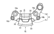
同燃料タンクキャップのヒンジ部材を示す斜視図である。
同ヒンジ部材を示す平面図である。
同ヒンジ部材を、図5の矢印VI方向から見た背面図である。
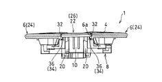
同燃料タンクキャップを図1の矢印VII方向から見た背面図である。
同燃料タンクキャップの変形例を示す背面図である。
以下、本発明の好ましい実施形態について図面を参照しながら説明する。
図1は、本発明の第1実施形態に係る燃料タンクキャップの平面図である。本発明の燃料タンクキャップ1は、例えば、自動二輪車のような鞍乗型乗物の燃料タンクFTの給油口2を開閉する。ただし、本発明の燃料タンクキャップ1は、自動二輪車の燃料タンクに限定されず、三輪車、四輪バギーのような陸上用の鞍乗型乗物、または小型滑走艇のような水上用の鞍乗型乗物の燃料タンクにも適用できる。
図1は、本発明の第1実施形態に係る燃料タンクキャップの平面図である。本発明の燃料タンクキャップ1は、例えば、自動二輪車のような鞍乗型乗物の燃料タンクFTの給油口2を開閉する。ただし、本発明の燃料タンクキャップ1は、自動二輪車の燃料タンクに限定されず、三輪車、四輪バギーのような陸上用の鞍乗型乗物、または小型滑走艇のような水上用の鞍乗型乗物の燃料タンクにも適用できる。
燃料タンクキャップ1は、円形の給油口2を開閉する円盤状のキャップ本体4と、給油口2の周りに配置されてキャップ本体4を囲う形状を有するリング部材6と、リング部材6に連結されてキャップ本体4を閉塞位置と開放位置との間に回動自在に支持するヒンジ部材8とを備えている。図1がキャップ本体4の閉塞位置を示し、図2がキャップ本体4の開放位置を示している。本発明の燃料タンクキャップ1は、エアプレーンタイプと呼ばれるもので、ヒンジ部材8のアーム部10が大きく湾曲し、キャップ本体4を燃料タンクFTの上面とほぼ面一にできる。これにより、燃料タンクキャップ1の見栄えがよい。
キャップ本体4は、図1の給油口2に合致する形状であり、本実施形態では、平面視で円形である。キャップ本体4には、キーシリンダ12が取り付けられている。詳細には、キャップ本体4の外表面(上面)にキーの差し込み口12aが設けられており、この差し込み口12aにキーを差し込んでまわすことで、キャップ本体4の施錠と解錠が行われる。差し込み口12aは、キーカバー(図示せず)により覆われている。
リング部材6は、給油口2の周りに配置され、キャップ本体4の外周を囲う形状を有している。リング部材6に、その径方向に横断する切欠部6aが形成されている。つまり、本実施形態のリング部材6は、平面視で、一部が切り欠かれた円環状である。換言すれば、リング部材6は、平面視で、C字形状である。
なお、以下の説明で、「軸方向」、「径方向」および「周方向」とはそれぞれ、リング部材6の「軸方向」、「径方向」および「周方向」のことをいう。燃料タンクキャップ1を燃料タンクFTに取り付けた状態では、「軸方向」が上下方向とほぼ一致する。
リング部材6は、例えば、樹脂材料のような安価で軽量な材料で形成されている。本実施形態では、リング部材6は、6,6-ナイロン製である。ただし、リング部材6の材質は、これに限定されず、例えば、ガラス繊維が入った繊維強化プラスチックであってもよく、また、アルミニウム合金であってもよい。
リング部材6における切欠部6aの近傍に、軸方向(上下方向)向くねじ孔6bが形成されている。本実施形態では、ねじ孔6bは、切欠部6aの周方向に隣接して1つずつ、計2つ設けられている。さらに、リング部材6における各ねじ孔6bと径方向にほぼ対向する位置に、径方向内側に突出する取付片6cが設けられている。各取付片6cに、軸方向(上下方向)を向く挿通孔6dが形成されている。
ヒンジ部材8は、例えば、金属材料で形成される。本実施形態のヒンジ部材8は、亜鉛合金で形成されている。亜鉛合金は、成形性がよく、丈夫である。ただし、ヒンジ部材8は、リング部材6と異なる材料で構成されていればよく、亜鉛合金に限定されない。ヒンジ部材8の材質は、例えば、鋼製であってもよく、また、金属以外の材料であってもよい。ヒンジ部材8は、リング部材6よりも強度の強い(剛性の高い)材料で構成されるのが好ましい。
図3に示すように、ヒンジ部材8は、回転軸心AX周りに回動する前記アーム部10と、アーム部10を回動自在に支持するヒンジ支持部14とを有している。詳細には、アーム部10は、回転軸心AXを有する回転軸16を有し、この回転軸16がヒンジ支持部14により支持されている。
アーム部10は、その基端部10aがヒンジ支持部14に支持され、先端部10bにキーシリンダ12が装着されている。基端部10aに、軸挿通孔10cが形成されている。アーム部10は、基端部10aから先端部10bにかけて大きく湾曲して、詳細には、ほぼ180°湾曲して、キーシリンダ12に繋がっている。アーム部10は、キーシリンダ12と一体に形成されてもよく、別体であってもよい。
図2に示すように、ヒンジ部材8は、ヒンジ支持部14を燃料タンクFTに取り付ける取付部18を有している。本実施形態では、ヒンジ支持部14と取付部18とが、軸方向に重ならないように径方向および周方向にずれている。詳細には、ヒンジ支持部14に対して、取付部18が、径方向内側で、かつ、周方向外側にずれて設けられている。
取付部18に、軸方向(上下方向)を向く挿通孔18aが形成されている。本実施形態では、挿通孔18aは2つ設けられているが、挿通孔18aの数はこれに限定されない。図4に示すように、ヒンジ支持部14における各挿通孔18aの近傍に、リング取付孔18bが形成されている。本実施形態では、各挿通孔18aの径方向外側に、リング取付孔18bが1つずつ形成されている。
ヒンジ支持部14は、周方向に並んだ一対の支持壁20,20を有している。支持壁20,20は、取付部18から軸方向(上方)に延びている。各支持壁20の上端部に、接線方向を向いた軸支持孔20aが形成されている。ヒンジ支持部14の支持壁20,20の上面は、天井部22で連結されている。
図1に示すように、ヒンジ部材8の一部分を構成する天井部22が、切欠部6aに配置されている。本実施形態では、平面視で、キャップ本体4の外周の大部分がリング部材6により覆われ、キャップ本体4の外周の一部分がヒンジ部材8(天井部22)により覆われている。
換言すれば、リング部材6におけるキャップ本体4の外周に対向する第1外周部分24が、ヒンジ部材8におけるキャップ本体4の外周に対向する第2外周部分26よりも周方向に大きく形成されている。本実施形態では、天井部22が、ヒンジ部材8の第2外周部分26を構成している。ここで、第1外周部分24は、例えば、キャップ本体4の外周の70%以上を覆うことが好ましい。第2外周部分26が大き過ぎると、燃料タンクキャップ1の重量が大きくなる。
図3に示す開放位置で、ヒンジ支持部14は、アーム部10が当接する当接部28を有している。本実施形態では、ヒンジ支持部14の天井部22に、当接部28が形成されている。詳細には、天井部22の下面に、当接部28が形成されている。つまり、当接部28を有する天井部22が、第2外周部分26を構成している。
図4に示すように、各支持壁20の周方向の外側面に、補強リブ30が形成されている。本実施形態の補強リブ30は、ほぼ四角柱形状である。ただし、補強リブ30の形状はこれに限定されない。また、補強リブ30はなくてもよい。
本実施形態では、ヒンジ部材8のヒンジ支持部14および取付部18は、型成形による一体成型品である。また、型の抜き方向は、軸方向(上下方向)である。具体的には、ヒンジ支持部14の支持壁20、天井部22(当接部28)および補強リブ30と、取付部18が、型成形により一体に形成されている。ただし、ヒンジ支持部14および取付部18の成形方法は、これに限定されず、例えば、削り出しであってもよい。
図1に示す樹脂製のリング部材6と金属製のヒンジ部材8が強く接触しないように、平面視で、リング部材6とヒンジ部材8の天井部22との間に、周方向の隙間32が形成されている。本実施形態の燃料タンクキャップ1は、平面視で、この隙間32を隠蔽する隠蔽構造34を備えている。
図7に示すように、切欠部6aを形成するリング部材6の各周方向端縁部に、延出部36,36が形成されている。両延出部36,36は、端縁部から下方に延びたのち、互いに接近する方向に周方向に延びている。つまり、延出部36は、隙間32およびヒンジ部材8の天井部22の下方に位置している。換言すれば、平面視で、第1外周部分24(リング部材6)の周方向端縁と第2外周部分26(天井部22)の周方向端縁がラップしている。これにより、平面視で、隙間32から内部が見えるのを防いでいる。つまり、延出部36が、平面視で隙間32を隠蔽する隠蔽構造34を構成している。
図8は、隠蔽構造34の変形例を示す。同図の例では、切欠部6aを形成するリング部材6の各周方向端縁部の下半部に、周方向内側に後退する凹部38が形成されている。一方、ヒンジ部材8の天井部22の各周方向端縁部の下半部に、周方向外側に突出する凸部40が形成されている。
このように、図8の変形例でも、平面視で、第1外周部分24(リング部材6)の周方向端縁と第2外周部分26(天井部22)の周方向端縁がラップしている。これにより、平面視で、隙間32から内部が見えるのを防いでいる。つまり、リング部材6の凹部38と、天井部22の凸部42が、平面視で隙間32を隠蔽する隠蔽構造34を構成している。
図8の例では、リング部材6に凹部38が設けられ、天井部22に凸部40が設けられているが、逆であってもよい。つまり、リング部材6に凸部を設け、天井部22に凹部を設けてもよい。また、凹部38および凸部40を省略して、隙間32の下方に補強リブ30が位置するようにしてもよい。この場合、補強リブ30が、平面視で隙間32を隠蔽する隠蔽構造34を構成する。
つぎに、燃料タンクキャップ1の組立/取付手順について説明する。まず、図3の回転軸16が、一方の支持壁20の軸支持孔20a(図4)、アーム部10の基端部10aの軸挿通孔10cおよび他方の支持壁20の軸支持孔20aの順に挿通される。これにより、アーム部10とヒンジ支持部14が連結されてヒンジ部材8が構成される。
つづいて、アーム部10に連結されたキーシリンダ12に、キャップ本体4が取り付けられる。キャップ本体4とキーシリンダ12は、例えば、ねじ体のような締結部材(図示せず)により連結される。さらに、ヒンジ部材8にリング部材6が取り付けられる。具体的には、ねじ体のような締結部材(図示せず)が下方から、図4のヒンジ支持部14の各リング取付孔18bに挿通され、図1のリング部材6の各ねじ孔6bに締め付けられる。以上により、燃料タンクキャップ1が組み立てられる。
つぎに、燃料タンクキャップ1が燃料タンクFTに取り付けられる。具体的には、ボルトのような締結部材(図示せず)が上方から、図4のヒンジ支持部14の各挿通孔18aに挿通され、図1の燃料タンクFTのねじ孔(図示せず)に締め付けられる。同様に、リング部材6の各取付片6cの挿通孔6dに、ボルトのような締結部材(図示せず)が上方から挿通され、燃料タンクFTのねじ孔(図示せず)に締め付けられる。以上により、燃料タンクキャップ1が燃料タンクFTに取り付けられる。
上記構成によれば、剛性を要するヒンジ部材8が金属材料で形成され、意匠部品であるリング部材6が樹脂材料で形成されている。さらに、ヒンジ部材8の一部である天井部22が、キャップ本体4の外周に対向する第2外周部分26を構成しており、キャップ本体とリング部材との間に配置されていない。したがって、ヒンジ部材8の大形化を図り易い。また、ヒンジ部材8の第2外周部分26が、リング部材6におけるキャップ本体4の外周を覆う第1外周部分24よりも周方向寸法が小さいので、タンクキャップ1の重量の増加を抑制できるうえに、外観が大きく損なわれることもない。
図3に示すアーム部10の回転軸16を支持するヒンジ支持部14が、図4の周方向に並んだ一対の支持壁20,20を有し、支持壁20,20の上面が天井部22で連結されている。さらに、この天井部22の下部に、図3の開放位置でアーム部10が当接する当接部28が形成されるとともに、当接部28を有する天井部22が第2外周部分26を構成している。このように、強度を必要とする当接部28(天井部22)が、第2外周部分26を構成しているので、当接部28を大形化することができる。これにより、当接部28の剛性を確保しやすい。したがって、開放位置でアーム部10を強固に支持できる。
キャップ本体4は、キーシリンダ12等を含んでおり、重量物である。したがって、開動作時の荷重が大きいので、当接部28の耐荷重性(剛性)が重要となる。従来は、一対の支持壁の上端部に、アーム部10が当接していた。この場合、アーム部10が各支持壁に点で当たるので、耐荷重性(剛性)を確保するのが難しかった。また、支持壁はリング部材6に近接しているので、一対の支持壁を天井部で繋げるのは困難であった。具体的には、リング部材6の表面(外面)を凹凸の少ない滑らかな面に仕上げようとすると、リング部材6が部分的に薄くなってしまい、リング部材6の厚さを均一にすると、燃料タンクキャップ1の外表面が部分的に盛り上がって見栄えが悪くなる。
上記構成では、図1の支持壁20,20の上面が天井部22で連結され、この天井部22が燃料タンクキャップ1の外表面の一部(第2外周部分26)を構成している。これにより、図3のアーム部10が天井部22の下部の当接部28に面(線)で当接する。したがって、当接部28の耐荷重性(剛性)を確保し易い。また、図2の車体への取付部18、キーシリンダ12を従来品と同じとすることで、既存の燃料タンクFTに取り付け可能で、既存のキャップ本体4を流用できる。
図5に示すように、ヒンジ部材8のヒンジ支持部14と取付部18とが、軸方向に重ならないように径方向および周方向にずれている。特に、ヒンジ支持部14と取付部18とが径方向にずれているので、天井部22と取付部18との間に、平面視で軸方向に貫通する空洞Gが生じる。その結果、上下方向に開閉する型成形によりヒンジ部材8を容易に形成できる。図1に示すように、リング部材6の第1外周部分24が、ヒンジ部材8の第2外周部分26よりも大きく形成されている。天井部22(第2外周部分26)が大き過ぎると、燃料タンクキャップ1の重量が大きくなるうえに、型成形時に抜き難くなる。そこで、天井部22(第2外周部分26)を最小限の大きさとして、大重量化を抑制しつつ、製造コストも抑えられている。
図6に示すように、支持壁20,20の周方向の外側面に補強リブ30が形成されている。天井部22(当接部28)の強度を確保するうえで、リング部材6との連結部であるリング取付孔18bと支持壁20との距離Lを短くするのが有利である。構造上、距離Lが大きくなる場合でも、補強リブ30で支持壁20が補強されるので、アーム部10を安定して支持できる。
図7および図8に示すように、リング部材6とヒンジ部材8の天井部22との隙間32を平面視で隠蔽する隠蔽構造34が設けられている。これにより、第1外周部分24と第2外周部分26との隙間32から内部が見えないので、外観が向上する。
本発明は、以上の実施形態に限定されるものでなく、本発明の要旨を逸脱しない範囲内で、種々の追加、変更または削除が可能である。例えば、上記実施形態では、本実施形態では、ヒンジ支持部14と取付部18とが径方向および周方向にずれていたが、径方向および周方向の一方にのみずれていてもよい。また、リング部材6とヒンジ部材8との隙間32を隠蔽する隠蔽構造34を備えていたが、このような隠蔽構造34はなくてもよい。したがって、そのようなものも本発明の範囲内に含まれる。
1 燃料タンクキャップ
2 給油口
4 キャップ本体
6 リング部材
8 ヒンジ部材
10 アーム部
14 ヒンジ支持部
16 回転軸
18 取付部
20 支持壁
22 天井部
24 第1外周部分
26 第2外周部分
28 当接部
30 補強リブ
32 隙間
34 隠蔽構造
AX 回転軸心
FT 燃料タンク
2 給油口
4 キャップ本体
6 リング部材
8 ヒンジ部材
10 アーム部
14 ヒンジ支持部
16 回転軸
18 取付部
20 支持壁
22 天井部
24 第1外周部分
26 第2外周部分
28 当接部
30 補強リブ
32 隙間
34 隠蔽構造
AX 回転軸心
FT 燃料タンク
Claims (7)
- 燃料タンクの給油口を開閉するキャップ本体と、
前記給油口の周りに配置されて前記キャップ本体を囲う形状を有するリング部材と、
前記リング部材に連結されて、前記キャップ本体を閉塞位置と開放位置との間に回動自在に支持するヒンジ部材と、を備え、
前記リング部材における前記キャップ本体の外周に対向する第1外周部分が、前記ヒンジ部材における前記キャップ本体の外周に対向する第2外周部分よりも周方向に大きく、
前記リング部材と前記ヒンジ部材が、異なる材料で構成されている燃料タンクキャップ。 - 請求項1に記載の燃料タンクキャップにおいて、前記ヒンジ部材が、回転軸心周りに回動するアーム部と、前記開放位置で前記アーム部が当接する当接部とを有し、
前記当接部が、前記第2外周部分を構成している燃料タンクキャップ。 - 請求項2に記載の燃料タンクキャップにおいて、前記アーム部は、前記回転軸心を有する回転軸を有し、
前記ヒンジ部材は、前記回転軸を支持するヒンジ支持部を有し、
前記ヒンジ支持部の天井部に、前記当接部が形成されている燃料タンクキャップ。 - 請求項3に記載の燃料タンクキャップにおいて、前記ヒンジ部材は、さらに、前記ヒンジ支持部を前記燃料タンクに取り付ける取付部を有し、
前記ヒンジ支持部と前記取付部とが、軸方向に重ならないように径方向または周方向にずれている燃料タンクキャップ。 - 請求項3または4に記載の燃料タンクキャップにおいて、前記ヒンジ支持部は、上面が前記天井部で連結される周方向に並んだ一対の支持壁と、前記支持壁の前記周方向の外側面に形成された補強リブとを有している燃料タンクキャップ。
- 請求項3から5のいずれか一項に記載の燃料タンクキャップにおいて、さらに、前記リング部材と前記ヒンジ部材の天井部との隙間を平面視で隠蔽する隠蔽構造を備えた燃料タンクキャップ。
- 請求項1から6のいずれか一項に記載の燃料タンクキャップにおいて、前記リング部材が樹脂材料からなり、前記ヒンジ部材が金属材料からなる燃料タンクキャップ。
Priority Applications (2)
| Application Number | Priority Date | Filing Date | Title |
|---|---|---|---|
| JP2021526914A JP7424590B2 (ja) | 2019-06-24 | 2020-06-19 | 燃料タンクキャップ |
| US17/527,879 US12139008B2 (en) | 2019-06-24 | 2021-11-16 | Fuel tank cap |
Applications Claiming Priority (2)
| Application Number | Priority Date | Filing Date | Title |
|---|---|---|---|
| JP2019-116522 | 2019-06-24 | ||
| JP2019116522 | 2019-06-24 |
Related Child Applications (1)
| Application Number | Title | Priority Date | Filing Date |
|---|---|---|---|
| US17/527,879 Continuation US12139008B2 (en) | 2019-06-24 | 2021-11-16 | Fuel tank cap |
Publications (1)
| Publication Number | Publication Date |
|---|---|
| WO2020262233A1 true WO2020262233A1 (ja) | 2020-12-30 |
Family
ID=74061613
Family Applications (1)
| Application Number | Title | Priority Date | Filing Date |
|---|---|---|---|
| PCT/JP2020/024123 Ceased WO2020262233A1 (ja) | 2019-06-24 | 2020-06-19 | 燃料タンクキャップ |
Country Status (3)
| Country | Link |
|---|---|
| US (1) | US12139008B2 (ja) |
| JP (1) | JP7424590B2 (ja) |
| WO (1) | WO2020262233A1 (ja) |
Families Citing this family (1)
| Publication number | Priority date | Publication date | Assignee | Title |
|---|---|---|---|---|
| TWD233506S (zh) * | 2023-10-30 | 2024-09-11 | 巨鎧精密工業股份有限公司 臺南市安南區科技二路50號 (中華民國) | 油箱蓋 |
Citations (3)
| Publication number | Priority date | Publication date | Assignee | Title |
|---|---|---|---|---|
| JPS521702B2 (ja) * | 1972-09-21 | 1977-01-17 | ||
| JP2001277869A (ja) * | 2000-03-31 | 2001-10-10 | Yamaha Motor Co Ltd | タンクキャップのブリーザ構造 |
| JP2007001473A (ja) * | 2005-06-24 | 2007-01-11 | Kawasaki Heavy Ind Ltd | 燃料タンクのタンクキャップ |
Family Cites Families (5)
| Publication number | Priority date | Publication date | Assignee | Title |
|---|---|---|---|---|
| US7258386B2 (en) * | 1999-04-27 | 2007-08-21 | 89908, Inc. | Fuel door assembly |
| US6352295B1 (en) * | 1999-04-27 | 2002-03-05 | American Moto Products, Inc. | Fuel door assembly |
| US6752448B1 (en) * | 2003-05-22 | 2004-06-22 | Mei-Chin Hsu | Fuel door assembly for automobile |
| JP5201702B1 (ja) | 2012-08-07 | 2013-06-05 | 三恭金属株式会社 | 燃料タンクキャップ |
| JP6922717B2 (ja) * | 2017-12-18 | 2021-08-18 | トヨタ自動車株式会社 | フューエルリッド構造 |
-
2020
- 2020-06-19 WO PCT/JP2020/024123 patent/WO2020262233A1/ja not_active Ceased
- 2020-06-19 JP JP2021526914A patent/JP7424590B2/ja active Active
-
2021
- 2021-11-16 US US17/527,879 patent/US12139008B2/en active Active
Patent Citations (3)
| Publication number | Priority date | Publication date | Assignee | Title |
|---|---|---|---|---|
| JPS521702B2 (ja) * | 1972-09-21 | 1977-01-17 | ||
| JP2001277869A (ja) * | 2000-03-31 | 2001-10-10 | Yamaha Motor Co Ltd | タンクキャップのブリーザ構造 |
| JP2007001473A (ja) * | 2005-06-24 | 2007-01-11 | Kawasaki Heavy Ind Ltd | 燃料タンクのタンクキャップ |
Also Published As
| Publication number | Publication date |
|---|---|
| JPWO2020262233A1 (ja) | 2020-12-30 |
| US12139008B2 (en) | 2024-11-12 |
| US20230025478A1 (en) | 2023-01-26 |
| JP7424590B2 (ja) | 2024-01-30 |
Similar Documents
| Publication | Publication Date | Title |
|---|---|---|
| CN101981339B (zh) | 推力滑动轴承 | |
| JP6267734B2 (ja) | 車両用サイドミラー | |
| JP5201702B1 (ja) | 燃料タンクキャップ | |
| US11548316B2 (en) | Wheel for a vehicle | |
| JP7424590B2 (ja) | 燃料タンクキャップ | |
| FR3064949A1 (fr) | Ouvrant de vehicule automobile. | |
| JP2011085230A (ja) | タンク及びタンクの製造方法 | |
| US20040037622A1 (en) | Ceramic ball-and-socket joint | |
| US10267355B2 (en) | Wheel bearing for a motor vehicle | |
| JP3907578B2 (ja) | 車両用ディスクブレーキ装置 | |
| WO2020016356A1 (fr) | Coupelle de butée de suspension à insert métallique et butée de suspension associée | |
| JP4021008B2 (ja) | スロットルバルブ | |
| CN216300942U (zh) | 一种汽车扶手箱盖 | |
| JP4615306B2 (ja) | 車両用成形品 | |
| JP4247375B2 (ja) | 車両用ミラー | |
| JP2008254552A (ja) | ドアミラーベースの取付構造 | |
| CN222555073U (zh) | 一种具有储物功能的电动摩托车油箱 | |
| CN222592025U (zh) | 一种预埋件紧固型塑料气密包装箱 | |
| JP7131353B2 (ja) | 鞍乗型車両の燃料タンク構造 | |
| JP7017332B2 (ja) | ストラットマウント | |
| JP6433432B2 (ja) | 廃棄物収集箱用のヒンジ付カバー | |
| JP2017154701A (ja) | 車両用サイドミラー | |
| FR3094924A1 (fr) | Doublure de hayon muni d’insert de renfort en matériau composite | |
| JP2019199802A (ja) | ウォーターポンプ | |
| JP7015718B2 (ja) | 燃料タンクの取付構造 |
Legal Events
| Date | Code | Title | Description |
|---|---|---|---|
| 121 | Ep: the epo has been informed by wipo that ep was designated in this application |
Ref document number: 20831577 Country of ref document: EP Kind code of ref document: A1 |
|
| ENP | Entry into the national phase |
Ref document number: 2021526914 Country of ref document: JP Kind code of ref document: A |
|
| NENP | Non-entry into the national phase |
Ref country code: DE |
|
| 122 | Ep: pct application non-entry in european phase |
Ref document number: 20831577 Country of ref document: EP Kind code of ref document: A1 |