WO2020262179A1 - 電子機器及び画像形成装置 - Google Patents
電子機器及び画像形成装置 Download PDFInfo
- Publication number
- WO2020262179A1 WO2020262179A1 PCT/JP2020/023876 JP2020023876W WO2020262179A1 WO 2020262179 A1 WO2020262179 A1 WO 2020262179A1 JP 2020023876 W JP2020023876 W JP 2020023876W WO 2020262179 A1 WO2020262179 A1 WO 2020262179A1
- Authority
- WO
- WIPO (PCT)
- Prior art keywords
- unit
- display
- state
- control unit
- open
- Prior art date
- Legal status (The legal status is an assumption and is not a legal conclusion. Google has not performed a legal analysis and makes no representation as to the accuracy of the status listed.)
- Ceased
Links
Images





Classifications
-
- B—PERFORMING OPERATIONS; TRANSPORTING
- B41—PRINTING; LINING MACHINES; TYPEWRITERS; STAMPS
- B41J—TYPEWRITERS; SELECTIVE PRINTING MECHANISMS, i.e. MECHANISMS PRINTING OTHERWISE THAN FROM A FORME; CORRECTION OF TYPOGRAPHICAL ERRORS
- B41J29/00—Details of, or accessories for, typewriters or selective printing mechanisms not otherwise provided for
-
- B—PERFORMING OPERATIONS; TRANSPORTING
- B41—PRINTING; LINING MACHINES; TYPEWRITERS; STAMPS
- B41J—TYPEWRITERS; SELECTIVE PRINTING MECHANISMS, i.e. MECHANISMS PRINTING OTHERWISE THAN FROM A FORME; CORRECTION OF TYPOGRAPHICAL ERRORS
- B41J29/00—Details of, or accessories for, typewriters or selective printing mechanisms not otherwise provided for
- B41J29/38—Drives, motors, controls or automatic cut-off devices for the entire printing mechanism
-
- G—PHYSICS
- G06—COMPUTING OR CALCULATING; COUNTING
- G06F—ELECTRIC DIGITAL DATA PROCESSING
- G06F1/00—Details not covered by groups G06F3/00 - G06F13/00 and G06F21/00
- G06F1/26—Power supply means, e.g. regulation thereof
- G06F1/32—Means for saving power
- G06F1/3203—Power management, i.e. event-based initiation of a power-saving mode
- G06F1/3206—Monitoring of events, devices or parameters that trigger a change in power modality
-
- G—PHYSICS
- G06—COMPUTING OR CALCULATING; COUNTING
- G06F—ELECTRIC DIGITAL DATA PROCESSING
- G06F1/00—Details not covered by groups G06F3/00 - G06F13/00 and G06F21/00
- G06F1/26—Power supply means, e.g. regulation thereof
- G06F1/32—Means for saving power
- G06F1/3203—Power management, i.e. event-based initiation of a power-saving mode
- G06F1/3234—Power saving characterised by the action undertaken
- G06F1/3287—Power saving characterised by the action undertaken by switching off individual functional units in the computer system
-
- G—PHYSICS
- G06—COMPUTING OR CALCULATING; COUNTING
- G06F—ELECTRIC DIGITAL DATA PROCESSING
- G06F3/00—Input arrangements for transferring data to be processed into a form capable of being handled by the computer; Output arrangements for transferring data from processing unit to output unit, e.g. interface arrangements
- G06F3/01—Input arrangements or combined input and output arrangements for interaction between user and computer
- G06F3/048—Interaction techniques based on graphical user interfaces [GUI]
- G06F3/0481—Interaction techniques based on graphical user interfaces [GUI] based on specific properties of the displayed interaction object or a metaphor-based environment, e.g. interaction with desktop elements like windows or icons, or assisted by a cursor's changing behaviour or appearance
- G06F3/0482—Interaction with lists of selectable items, e.g. menus
-
- G—PHYSICS
- G06—COMPUTING OR CALCULATING; COUNTING
- G06F—ELECTRIC DIGITAL DATA PROCESSING
- G06F3/00—Input arrangements for transferring data to be processed into a form capable of being handled by the computer; Output arrangements for transferring data from processing unit to output unit, e.g. interface arrangements
- G06F3/12—Digital output to print unit, e.g. line printer, chain printer
-
- H—ELECTRICITY
- H04—ELECTRIC COMMUNICATION TECHNIQUE
- H04N—PICTORIAL COMMUNICATION, e.g. TELEVISION
- H04N1/00—Scanning, transmission or reproduction of documents or the like, e.g. facsimile transmission; Details thereof
Definitions
- the present invention relates to an electronic device and an image forming apparatus, and more particularly to a technique for switching a setting screen.
- Patent Document 1 discloses a technique for switching a call mode according to a folded state or an opened state.
- Patent Document 2 discloses a technique of selecting a display area according to a bent posture and performing display control on the selected display area.
- the user needs to perform a touch operation on the touch panel, for example, in order to switch the setting screen, which is troublesome. Further, when it is desired to use the detail screen and the simple screen properly according to the function, the user has to perform a touch operation for switching the setting screen each time, which is inconvenient.
- Patent Documents 1 and 2 are merely techniques for using a foldable display, not a technique for switching between a simple screen and a setting screen, and thus have the above-mentioned problems. Cannot be solved.
- the present invention has been made in view of the above circumstances, and an object of the present invention is to save the user time and effort required for switching the setting screen and to display a setting screen suitable for the user.
- the electronic device includes a display unit including a first display surface that is not foldable, a second display surface that is foldable, and a second display surface that is folded. It includes an open / close detection unit for detecting an open or open state, an input unit for inputting a user's instruction, and a control unit.
- the control unit has detected a folded state by the open / close detection unit, and receives a selection instruction for selecting at least one of the executable functions via the input unit.
- the display unit displays a simple screen for easily setting the selected function on the exposed first display surface with the second display surface folded, and opens and closes.
- the image forming apparatus includes the above-mentioned electronic device and an image forming unit for forming an image on a recording medium.
- the control unit causes the image forming unit to form an image according to the received setting contents.
- the user can switch the display between the simple screen and the detailed screen by a simple operation of folding and opening the display unit. Therefore, it is possible to save the user's trouble of switching the display screen.
- a user who is not accustomed to the operation for making settings does not have to make settings from the detail screen, so that the settings can be made without confusion.
- a user who is accustomed to the operation for making settings can make detailed settings without making settings from a simple screen. Therefore, the convenience of the user is improved.
- FIG. 1 is a perspective view showing the appearance of the image forming apparatus.
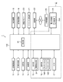
- FIG. 2 is a block diagram showing an internal configuration of the image forming apparatus.
- the image forming apparatus 1 is a color multifunction device having a plurality of functions such as a facsimile function, a copy function, a printer function, and a scanner function.
- the image forming apparatus 1 includes a control unit 100.
- the control unit 100 includes a processor, a RAM (Random Access Memory), a ROM (Read Only Memory), and the like.
- the processor is, for example, a CPU (Central Processing Unit), an MPU (Micro Processing Unit), an ASIC (Application Specific Integrated Circuit), or the like.
- the control unit 100 functions as a control unit 10 when a control program stored in a ROM or HDD (Hard Disk Drive) 17 is executed by the processor.
- the control unit 10 controls the overall control of the image forming apparatus 1. For example, the control unit 10 performs a process of changing the screen displayed on the display unit 15 according to the folded state or the open state of the display unit 15.
- the control unit 10 may be configured by a hard circuit regardless of the operation based on the control program.
- the control unit 100 includes an image reading unit 11, an image forming unit 12, a fixing unit 13, a paper feeding unit 14, a display unit 15, an operation unit 16, HDD 17, a transport mechanism 18, an image processing unit 19, an image memory 20, and a facsimile communication unit. It is electrically connected to 21, the communication unit 22, the power supply unit 24, and the like.
- the control unit 100, the display unit 15, the operation unit 16, the HDD 17, and the power supply unit 24 function as the electronic device 2 according to the embodiment of the present invention.
- the image reading unit 11 includes a document conveying unit that conveys a document placed on a platen, a scanner that optically reads a document conveyed by the document conveying unit or a document placed on a platen glass, and the like. It is an ADF (Auto Document Feeder) containing.
- the image reading unit 11 irradiates the document with the light irradiation unit and receives the reflected light with the CCD (Charge-Coupled Device) sensor to read the document and generate image data.
- CCD Charge-Coupled Device
- the image forming unit 12 includes a photoconductor drum, a charging device, an exposure device, a developing device, and a transfer device.
- the image forming unit 12 forms an image composed of a toner image on the recording paper conveyed from the feeding unit 14 based on the image data or the like generated by the image reading unit 11.
- the fixing unit 13 fixes the toner image on the recording paper by heating and pressurizing the recording paper on which the toner image is formed by the image forming unit 12.
- the recording paper on which the toner image is fixed by the fixing unit 13 is discharged to the discharge tray 8.
- the paper feed unit 14 includes a manual feed tray and a paper feed cassette.
- the paper feed unit 14 pulls out the recording paper housed in the paper feed cassette or the recording paper placed on the manual feed tray one by one, and feeds the paper to the image forming unit 12.
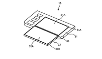
- FIG. 3A is a diagram showing a state when the display unit 15 is open.
- FIG. 3B is a diagram showing a state when the display unit 15 is folded.
- the display unit 15 includes a first housing 31 having a substantially rectangular parallelepiped shape and a second housing 32 having a substantially rectangular parallelepiped shape.
- a first display device 31A is provided on one surface of the first housing 31.
- a second display device 32A is provided on one surface of the second housing 32 (hereinafter referred to as “first surface”).
- a third display device 32B is provided on a surface of the second housing 32 opposite to the first surface (hereinafter, referred to as “second surface”).
- the first housing 31 and the second housing 32 have a display surface of the first display device 31A and a second display via a rotation shaft 33 extending along the longitudinal direction of the first housing 31 and the second housing 32. It is foldably connected so that it faces the display surface of the device 32A.
- the case where the angle formed by the first housing 31 and the second housing 32 exceeds 90 degrees is defined as a state in which the display unit 15 is open (hereinafter, referred to as an “open state”).
- the display unit 15 is in a folded state (hereinafter, referred to as a “closed state”).
- the first display device 31A, the second display device 32A, and the third display device 32B are composed of, for example, a liquid crystal display.
- FIG. 3B when the display unit 15 is in the closed state, the display surface of the third display device 32B is in a state of being exposed above the display unit 15 in the vertical direction, that is, on the user side.
- FIG. 3A when the display unit 15 is in the open state, the display surface of the first display device 31A and the display surface of the second display device 32A are exposed above the display unit 15 in the vertical direction, that is, to the user side. It will be in a state of being.
- the control unit 10 presets the display surface of the third display device 32B as the "first display surface”.
- the control unit 10 also presets the display surface of the first display device 31A and the display surface of the second display device 32A as the "second display surface”.
- the control unit 10 causes the display unit 15 to display various screens related to each function and the like that can be executed by the image forming apparatus 1 on the first display surface or the second display surface.
- the display unit 15 includes an open / close detection unit 34 for detecting a closed state or an open state of the display unit 15.
- the open / close detection unit 34 is composed of a Hall IC (Integrated Circuit) 34A provided in the first housing 31 and a magnet 34B provided in the second housing 32.
- the Hall IC 34A includes a Hall element that detects the magnitude of the magnetic flux density generated from the magnet 34B.
- the Hall IC 34A outputs a first signal indicating that the display unit 15 is in the open state when the value indicating the magnitude of the magnetic flux density detected by the Hall element is equal to or less than a predetermined value.
- the Hall IC 34A outputs a second signal indicating that the display unit 15 is in the closed state when the value indicating the magnitude of the detected magnetic flux density exceeds a predetermined value.
- the operation unit 16 includes a touch panel 16A which is arranged so as to overlap the first display surface and the second display surface, respectively.
- the operation unit 16 also includes a plurality of hard keys such as a start key 16B for instructing the start of execution of various functions.
- the user inputs various information such as instructions for executing various functions that can be executed by the image forming apparatus 1 via the operation unit 16.
- the operation unit 16 is an example of an input unit within the scope of claims.
- the HDD 17 is a large-capacity storage device for storing various data such as image data generated by the image reading unit 11.
- the HDD 17 stores various control programs for realizing the general operation of the image forming apparatus 1.
- the HDD 17 stores, as one of various control programs, a change program for executing the display screen change process according to the embodiment of the present invention.
- the HDD 17 stores image data for displaying the home screen (hereinafter, simply referred to as “home screen”).
- the home screen is a selection screen for selecting one of a plurality of functions that can be executed by the image forming apparatus 1.
- the HDD 17 stores image data for displaying a detailed screen (hereinafter, simply referred to as a “detailed screen”) in association with each of a plurality of functions that can be executed by the image forming apparatus 1.
- the detail screen is a screen for making detailed settings for the associated function.
- the HDD 17 stores image data for displaying a simple screen (hereinafter, simply referred to as “simple screen”) in association with each of a plurality of functions that can be executed by the image forming apparatus 1.
- the simple screen is a screen for easily setting the associated function.
- the transport mechanism 18 is composed of a pair of transport rollers and a pair of discharge rollers.
- the transport mechanism 18 transports the recording paper along the transport path toward the discharge tray 8 set as the discharge destination.
- the image processing unit 19 executes image processing on the image data generated by the image reading unit 11 as necessary.
- the image memory 20 includes an area for temporarily storing the image data to be output generated by the image reading unit 11.
- the facsimile communication unit 21 connects to a public line and transmits / receives image data via the public line.
- the communication unit 22 includes a communication module such as a LAN (Local Area Network) board.
- the image forming apparatus 1 performs data communication with an external device 23 such as a PC (Personal Computer) connected via a network via the communication unit 22.
- an external device 23 such as a PC (Personal Computer) connected via a network via the communication unit 22.
- the power supply unit 24 controls the supply of electric power from the power source to each unit of the image forming apparatus 1.
- the power supply unit 24 includes a switching unit 24A.
- the switching unit 24A is a switch that switches between an energized state in which power from the power supply is supplied to the display unit 15 and the touch panel 16A and a non-energized state in which power from the power supply is not supplied to the display unit 15 and the touch panel 16A. ..
- [motion] 4A and 4B are flowcharts showing a display screen change process.
- the operation of the image forming apparatus 1 at the time of executing the display screen change processing will be described with reference to FIGS. 4A and 4B.
- the display unit 15 is in the closed state when the power of the image forming apparatus 1 is not turned on.
- the control unit 10 causes the power supply unit 24 to start supplying electric power to each part of the image forming apparatus 1 except the display unit 15. At this time, it is assumed that the control unit 10 keeps the state of the display unit 15 in the non-energized state without causing the switching unit 24A to start supplying power to the display unit 15. Even when the display unit 15 is in the non-energized state, it is assumed that the power supply unit 24 supplies power to the open / close detection unit 34.
- the control unit 10 also starts executing the display screen change process when the power of the image forming apparatus 1 is turned on.
- the control unit 10 determines whether or not the display unit 15 is in the open state based on the signal output from the open / close detection unit 34 (step S10). .. At this time, the control unit 10 repeats the process of determining that the display unit 15 is not in the open state (NO in step S10).
- step S10 determines that the display unit 15 is in the open state based on the first signal output from the open / close detection unit 34 (YES in step S10), and causes the switching unit 24A to supply electric power to the display unit 15. By starting the supply, the state of the display unit 15 is switched from the non-energized state to the energized state (step S11). After switching to the energized state, the control unit 10 determines whether or not a selection instruction for selecting one of the plurality of functions that can be executed by the image forming apparatus 1 is received (step S12).
- step S12 When the selection instruction is not accepted
- step S13 it is determined whether or not the first display device 31A and the second display device 32A are displaying the home screen. In this case, since the control unit 10 does not display anything on the first display device 31A and the second display device 32A, it is determined that the home screen is not displayed (NO in step S13), and the home from the HDD 17 is displayed. Read the screen (step S14).
- FIG. 5 is a diagram showing an example of a home screen.
- the control unit 10 transmits to the first display device 31A and the second display device 32A as soft keys, a key 52 for inputting a selection instruction for selecting a copy function, and a transmission. It is assumed that the home screen 50 including the key 54 and the like for inputting the selection instruction for selecting the function is displayed.
- the control unit 10 causes the first display device 31A to display a portion 50A located on one end side of the direction X orthogonal to the rotation axis 33 on the home screen 50 on the display surface of the first display device 31A.
- the portion 50B located on the other end side of the direction X on the home screen 50 is displayed on the display surface of the second display device 32A.
- step S16 the control unit 10 determines whether or not the display unit 15 is in the closed state based on the signal output from the open / close detection unit 34 (step S16). In this case, since the display unit 15 remains open, the control unit 10 determines that the display unit 15 is not in the closed state based on the first signal output from the open / close detection unit 34 (in step S16). NO), the process proceeds to step S12.
- the control unit 10 determines that the selection instruction is not received (NO in step S12) until the selection instruction is received or the display unit 15 is closed, and the process of determining that the home screen is displayed. (YES in step S13), and the process of determining that the display unit 15 is not in the closed state (NO in step S16) is repeated without executing the process of step S14 and the process of step S15.
- step S12 determines that the selection instruction for selecting the copy function is received (YES in step S12), and the first display device 31A and the first display device 31A 2 It is determined whether or not the display device 32A is displaying the detail screen associated with the selected function (step S17).
- control unit 10 determines that the detailed screen is not displayed because the home screen 50 is displayed on the first display device 31A and the second display device 32A (NO in step S17), and the HDD 17 Reads the detail screen associated with the selected function from (step S18). In this case, the control unit 10 reads the detailed screen associated with the copy function from the HDD 17.
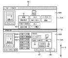
- FIG. 6 is a diagram showing an example of a detailed screen.
- the detail screen 60 includes a first screen 60A located on one end side of the direction X and a second screen 60B located on the other end side of the direction X.
- the first screen 60A is a screen for selecting a setting item to be set.
- the second screen 60B is a screen for making detailed settings for the selected setting item.
- the control unit 10 has a key 61 for inputting an instruction for selecting a setting item "paper selection” as a soft key to the first display device 31A, and a setting item "double-sided printing". It is assumed that the first screen 60A including the key 62 and the like for inputting the instruction for selecting is displayed on the display surface of the first display device 31A. It is assumed that the user touches the key 62. When the control unit 10 receives a touch operation on the key 62 via the touch panel 16A, the second screen for making detailed settings for the selected setting item "double-sided printing" for the second display device 32A. 60B is displayed on the display surface of the second display device 32A.
- the control unit 10 inputs an instruction to the second display device 32A as a soft key to select a set value of "single-sided to single-sided” indicating that the single-sided original is copied to one side of the recording paper.
- Enter the instruction to select the binding direction of the original according to the selected setting value such as the key 63C for inputting the instruction to select the setting value "double-sided to double-sided” indicating copying.
- Key 64 and key 65 for inputting key 66 for inputting an instruction for selecting the placement direction of the original according to the selected set value, and inputting a canceling instruction for deselecting the copy function.
- the second screen 60B including the key 67 for inputting the key 67 and the key 68 for inputting the confirmation instruction for confirming the setting contents is displayed.
- the control unit 10 receives a touch operation on the key 63A and the key 68 via the touch panel 16A, and the display content of the key 62 is displayed on the display unit 15. Is changed from the character string "one side to both sides" to the character string "one side to one side".
- step S16 After displaying the detail screen 60, the control unit 10 proceeds to the process of step S16. In this case, since the display unit 15 remains open, the control unit 10 determines that the display unit 15 is not in the closed state based on the first signal output from the open / close detection unit 34 (in step S16). NO), the process proceeds to step S12.
- the control unit 10 determines that the selection instruction is being accepted (YES in step S12) and the detail screen 60 is displayed until the display unit 15 is closed or the release instruction is received.
- the process (YES in step S17) and the process of determining that the display unit 15 is not in the closed state (NO in step S16) are repeated without executing the processes of steps S18 and S19.
- step S20 When the display unit 15 is in the closed state The user confirms the detail screen 60 and assumes that the display unit 15 is closed.
- the control unit 10 determines that the display unit 15 is in the closed state based on the second signal output from the open / close detection unit 34 (YES in step S16), and issues a selection instruction as shown in FIG. 4B. It is determined whether or not the signal is accepted (step S20).
- step S20 determines that the selection instruction is accepted (YES in step S20), and displays the third display. It is determined whether or not the device 32B is displaying the simple screen associated with the selected function (step S21).
- control unit 10 determines that the simple screen is not displayed because the detail screen 60 is displayed on the first display device 31A and the second display device 32A (NO in step S21), and the HDD 17 From, the simple screen associated with the selected function is read (step S22). In this case, the control unit 10 reads the simple screen associated with the copy function from the HDD 17.
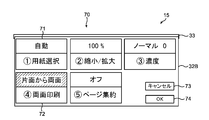
- FIG. 7 is a diagram showing an example of a simple screen.
- the control unit 10 inputs to the third display device 32B as a soft key an instruction for changing the setting value for the setting item "paper selection".
- a key 73 for inputting a release instruction for deselecting the copy function such as a key 72 for inputting an instruction for changing a setting value for a setting item "double-sided printing", and It is assumed that the simple screen 70 including the key 74 for inputting the confirmation instruction for confirming the setting content is displayed.
- the control unit 10 receives a touch operation on the key 72 via the touch panel 16A, and is selected according to the change order of the set values stored in advance in the HDD 17. Change the setting value for the setting item "double-sided printing" from the currently set “single-sided to double-sided” setting value to the "double-sided to double-sided” setting value.
- step S24 the control unit 10 determines whether or not the display unit 15 is in the open state based on the signal output from the open / close detection unit 34 (step S24). In this case, since the display unit 15 remains closed, the control unit 10 determines that the display unit 15 is not in the open state based on the second signal output from the open / close detection unit 34 (in step S24). NO), the process proceeds to step S20.
- the control unit 10 determines that the simple screen 70 is displayed in the process of determining that the selection instruction is being accepted (YES in step S20) until the release instruction is received or the display unit 15 is opened.
- the process (YES in step S21) and the process of determining that the display unit 15 is not in the open state (NO in step S24) are repeated without executing the processes of steps S22 and S23.
- the control unit 10 accepts the input setting content as the confirmed setting content. After touching the key 74, it is assumed that the user places the original on the platen glass of the image reading unit 11 and presses the start key 16B in order to start copying.
- control unit 10 When the control unit 10 detects that the start key 16B is pressed, the control unit 10 causes the image reading unit 11 to read the document placed on the platen glass according to the determined setting contents and generate image data. After the image data is generated, the control unit 10 causes the image forming unit 12 and the like to form an image based on the generated image data on the recording paper according to the determined setting contents.
- step S20 When the selection instruction is not accepted It is assumed that the user touches the key 73 of the simple screen 70 after the copying is completed.
- the control unit 10 determines that the selection instruction is not received (NO in step S20), and the display unit 15 determines that the switching unit 24A has switched. It is determined whether or not the power is on (step S25).
- control unit 10 determines that the display unit 15 is in the energized state (YES in step S25), and causes the switching unit 24A to cut off the power supply to the display unit 15 to change the state of the display unit 15. Switching from the energized state to the non-energized state (step S26). As a result, the display unit 15 shifts to the sleep mode, and the screen is not displayed on the first display surface and the second display surface.
- step S24 the control unit 10 determines that the display unit 15 is not in the open state based on the second signal output from the open / close detection unit 34 (in step S24). NO), the process proceeds to step S20.
- the control unit 10 determines that the selection instruction is not received (NO in step S20) until the selection instruction is received or the display unit 15 is opened, and the display unit 15 determines that the power is not supplied.
- the process (NO in step S25) and the process of determining that the display unit 15 is not in the open state (NO in step S24) are repeated without executing the process of step S26.
- step S24 determines that the display unit 15 is in the open state based on the first signal output from the open / close detection unit 34 (step S24). YES), and it is determined whether or not the display unit 15 is in the non-energized state (step S25). In this case, the control unit 10 determines that the display unit 15 is in the non-energized state (YES in step S25), and proceeds to the process of step S11. When the control unit 10 determines that the display unit 15 is not in the non-energized state (NO in step S25), the control unit 10 proceeds to the process of step S12.
- the control unit 10 when the closed state is detected by the open / close detection unit 34 and the selection instruction is received via the operation unit 16, the control unit 10 is displayed on the third display device 32B.
- the simple screen 70 associated with the selected function is displayed on the first display surface.
- the control unit 10 also causes the first display device 31A and the second display device 32A when the open state is detected by the open / close detection unit 34 and the selection instruction is received via the operation unit 16.
- the detail screen 60 associated with the selected function is displayed on the second display surface.
- the user can switch the display between the simple screen 70 and the detailed screen 60 by a simple operation of folding or opening the display unit 15. Therefore, it is possible to save the user's trouble of switching the setting screen. Further, a user who is not accustomed to the operation for performing the setting does not have to perform the setting from the detail screen 60, so that the setting can be performed without confusion. On the other hand, a user who is accustomed to the operation for making settings can make detailed settings without making settings from the simple screen 70. Therefore, the convenience of the user is improved.
- the control unit 10 when the open state is detected by the open / close detection unit 34 and the selection instruction is not received via the operation unit 16, the control unit 10 has the first display device 31A and The home screen 50 is displayed on the second display surface by the second display device 32A.
- the user can display the home screen 50 by a simple operation of opening the display unit 15 when none of the plurality of functions is selected.
- the user can easily perform an operation for selecting one of the plurality of functions as needed.
- the control unit 10 when the closed state is detected by the open / close detection unit 34 and the selection instruction is not received via the operation unit 16, the control unit 10 is displayed on the switching unit 24A.
- the state of the unit 15 is switched from the energized state to the non-energized state.
- the user can switch the state of the display unit 15 to the non-energized state by a simple operation of folding the display unit 15. Therefore, the user can easily reduce the wasteful power consumption.
- the control unit 10 when the state of the display unit 15 is in the non-energized state and the open / close detection unit 34 detects the open state, the control unit 10 causes the switching unit 24A to display the display unit 15. The state of is switched from the non-energized state to the energized state.
- the user can switch the state of the display unit 15 from the non-energized state to the energized state by a simple operation of opening the display unit 15. Therefore, the convenience of the user is further improved.
- the control unit 10 causes the image forming unit 12 and the like to form an image according to the received setting contents.
- the user can perform the execution in the image forming unit 12 or the like by using the electronic device 2 provided in the image forming apparatus 1, among a plurality of functions such as a copy function, a facsimile function, and a printer function. Since it is possible to make settings for the selected function of, the convenience of the user is further improved.
- control unit 10 determines whether or not the display unit 15 is in the energized state in the process of step S25, but the present invention is not limited to such an embodiment.
- control unit 10 may be configured to determine whether or not the home screen 50 is displayed on the first display device 31A and the second display device 32A in the process of step S25.
- control unit 10 proceeds to the process of step S26 when the home screen 50 is displayed on the first display device 31A and the second display device 32A (YES in step S25).
- control unit 10 does not display the home screen 50 on the first display device 31A and the second display device 32A and displays another screen different from the home screen 50 (step S25). NO), the process proceeds to step S24.
- control unit 10 when the control unit 10 receives a touch operation on the key 56 via the touch panel 16A, the control unit 10 opens and closes, for example, the display unit 15 on the second display surface with respect to the first display device 31A and the second display device 32A. It is assumed that another screen different from the home screen 50 is displayed, such as a help screen showing an explanation of the display screen according to the state.
- the control unit 10 when the control unit 10 displays the home screen 50 on the first display device 31A and the second display device 32A and the open / close detection unit 34 detects the closed state,
- the switching unit 24A switches the state of the display unit 15 from the energized state to the non-energized state.
- the control unit 10 also displays a screen different from the home screen 50 on the first display device 31A and the second display device 32A, and when the open / close detection unit 34 detects a closed state, the control unit 10 is a switching unit.
- the 24A is not allowed to perform the above-mentioned switching from the energized state to the non-energized state.
- the state of the display unit 15 can be switched to the non-energized state by folding the display unit 15.
- the state of the display unit 15 is switched to the non-energized state, which is useless. Power consumption can be easily suppressed.
- the user also sees the display unit 15 even if the display unit 15 is folded when a screen different from the home screen 50 such as a help screen is displayed, that is, when some operation is performed by the user. Can be maintained in the energized state. In this way, when some operation is performed by the user and there is a high possibility that the user wants to use the image forming apparatus 1, the state of the display unit 15 is switched to the non-energized state. Can be prevented.
- the electronic device 2 is provided in the image forming apparatus 1, but the present invention is not limited to such an embodiment.
- the second embodiment of the present invention is the same as the first embodiment except that the electronic device is provided separately from the image forming apparatus 1.
- the terminal device as an electronic device according to the second embodiment of the present invention will be described with reference to the drawings.
- FIG. 8 is a block diagram showing the internal configuration of the terminal device.
- the terminal device 3 is a tablet-type display device.
- the terminal device 3 includes a control unit 200.
- the control unit 200 is electrically connected to a display unit 81, a touch panel 82, an open / close detection unit 83, a storage unit 84, a communication unit 85, a power supply unit 86, and the like.
- the control unit 200 includes a processor, RAM, ROM, and the like.
- the processor is, for example, a CPU, MPU, ASIC, or the like.
- the control unit 200 functions as the control unit 80 when the control program stored in the ROM or the storage unit 84 is executed by the processor.
- the control unit 80 controls the entire terminal device 3. For example, the control unit 80 performs a process of changing the screen displayed on the display unit 81 according to the folded state or the open state of the display unit 81.
- the control unit 80 also controls communication with the image forming apparatus 1 connected via the network.
- the control unit 80 may be configured by a hard circuit regardless of the operation based on the control program.
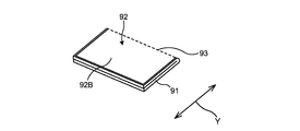
- FIG. 9A is a diagram showing a state when the display unit is open.
- FIG. 9B is a diagram showing a state when the display unit is folded.
- the display unit 81 includes a substantially rectangular parallelepiped housing 91.
- a display device 92 is provided on one surface of the housing 91.
- the display device 92 is composed of, for example, a liquid crystal display.
- the touch panel 82 is arranged so as to overlap the display device 92.
- the user inputs various information such as instructions for executing various functions that can be executed by the terminal device 3 via the touch panel 82.
- the touch panel 82 is an example of an input unit within the scope of claims.
- the housing 91, the display device 92, and the touch panel 82 are configured to be foldable with the display surface of the display device 92 exposed to the outside centering on the center line 93.
- the display surface of the display device 92 is folded so that the display area 92A located on one end side in the direction Y orthogonal to the center line 93 and the display area 92B located on the other end side in the direction Y. It is divided into.
- the display unit 81 when the angle formed by the display area 92A and the display area 92B exceeds 90 degrees, the display unit 81 is in an open state (hereinafter, referred to as an “open state”). When the angle formed by the display area 92A and the display area 92B is 90 degrees or less, the display unit 81 is in a folded state (hereinafter, referred to as “closed state”).
- the control unit 80 sets the display area 92A or the display area 92B exposed upward in the vertical direction of the terminal device 3 as the “first display surface”. For example, as shown in FIG. 9B, when the display unit 81 is closed, the display area 92B is exposed upward in the vertical direction of the terminal device 3, so that the control unit 10 displays the display area 92B as “first display”. Set to "face”.
- the control unit 80 also presets the entire display surface of the display device 92, that is, the display area 92A and the display area 92B as the “second display surface”. For example, FIG. 9A shows a state in which the second display surface is exposed upward in the vertical direction of the terminal device 3 when the display unit 81 is in the open state.
- the control unit 80 causes the display unit 81 to display various screens related to each function and the like that can be executed by the image forming apparatus 1 on the first display surface or the second display surface.
- the open / close detection unit 83 includes a 3-axis acceleration sensor.
- the 3-axis acceleration sensor detects the movement of the display unit 81 in the 3-axis direction as an acceleration, and outputs a signal indicating the detected acceleration.
- the storage unit 84 is a storage device such as a flash memory.
- the storage unit 84 stores various control programs for realizing the general operation of the terminal device 3.
- the storage unit 84 stores, as one of various control programs, a change program for executing the same display screen change process as in the first embodiment.
- the storage unit 84 stores the home screen.
- the storage unit 84 stores the detail screen in association with each of the plurality of functions that can be executed by the image forming apparatus 1.
- the storage unit 84 stores the simple screen in association with each of the plurality of functions that can be executed by the image forming apparatus 1.
- the communication unit 85 includes a communication module.
- the terminal device 3 performs data communication with the image forming device 1 connected via the network via the communication unit 85.
- the power supply unit 86 controls the supply of electric power from the power source to each unit of the terminal device 3.
- the power supply unit 86 includes a switching unit 86A.
- the switching unit 86A is a switch that switches between an energized state in which power from the power supply is supplied to the display unit 81 and the touch panel 82 and a non-energized state in which power from the power supply is not supplied to the display unit 81 and the touch panel 82. ..
- the control unit 80 causes the power supply unit 86 to start supplying electric power to each unit of the terminal device 3 except the display unit 81.
- the control unit 80 keeps the state of the display unit 81 in the non-energized state without causing the switching unit 86A to start supplying power to the display unit 81.
- the power supply unit 86 supplies power to the open / close detection unit 83.
- the control unit 80 also starts executing the display screen change process when the power of the terminal device 3 is turned on. With reference to FIG. 4A, in the display screen change process, the control unit 80 determines whether or not the display unit 81 is in the open state based on the signal output from the open / close detection unit 83 (step S10). ..
- control unit 80 calculates the angle formed by the display area 92A and the display area 92B based on the signal output from the open / close detection unit 83, and when the calculated angle exceeds 90 degrees. It is determined that the display unit 81 is in the open state. The control unit 80 determines that the display unit 81 is in the closed state when the calculated angle is 90 degrees or less. At this time, the control unit 10 repeats the process of determining that the display unit 15 is not in the open state (NO in step S10).
- step S10 When the display unit 81 is in the open state After the power of the terminal device 3 is turned on, the user assumes that the display unit 81 is opened.
- the control unit 80 determines that the display unit 81 is in the open state based on the signal output from the open / close detection unit 83 (YES in step S10), and causes the switching unit 86A to change the state of the display unit 81.
- the energized state is switched to the energized state (step S11). After switching to the energized state, the control unit 80 determines whether or not a selection instruction for selecting one of the plurality of functions that can be executed by the image forming apparatus 1 is received (step S12).
- step S12 When the selection instruction is not accepted
- step S13 since the terminal device 3 has just been turned on and the user has not selected the function, the control unit 80 has received the selection instruction. It is determined that there is no such (NO in step S12), and it is determined whether or not the home screen 50 is displayed on the display device 92 (step S13). In this case, since the control unit 80 does not display anything on the display device 92, it is determined that the home screen 50 is not displayed (NO in step S13), and the home screen 50 is read from the storage unit 84. (Step S14).
- the control unit 80 After reading the home screen 50, the control unit 80 causes the display device 92 to display the read home screen 50 on the second display surface (step S15). The control unit 80 causes the display device 92 to display the portion 50A on the home screen 50 in the display area 92A and display the portion 50B on the home screen 50 in the display area 92B. In this way, the control unit 80 displays the home screen 50 on the entire display surface of the display device 92.
- the control unit 80 determines whether or not the display unit 81 is in the closed state based on the signal output from the open / close detection unit 83 (step S16). In this case, since the display unit 81 remains open, the control unit 80 determines that the display unit 81 is not in the closed state (NO in step S16), and proceeds to the process of step S12.
- the control unit 80 determines that the selection instruction is not received (NO in step S12) until the selection instruction is received or the display unit 81 is closed, and the home screen 50 is displayed.
- the process (YES in step S13) and the process of determining that the display unit 81 is not in the closed state (NO in step S16) are repeated without executing the process of step S14 and the process of step S15.
- step S12 determines that the selection instruction for selecting the copy function is received (YES in step S12), and is selected by the display device 92. It is determined whether or not the detail screen associated with the function is displayed (step S17).
- control unit 80 since the control unit 80 displays the home screen 50 on the display device 92, it determines that the detail screen is not displayed (NO in step S17), and the function selected from the storage unit 84.
- the detail screen associated with is read (step S18). In this case, the control unit 80 reads the detail screen 60 associated with the copy function from the storage unit 84.
- the control unit 80 After reading the detail screen 60, the control unit 80 causes the display device 92 to display the read detail screen 60 on the second display surface (step S19). In this case, the control unit 80 causes the display device 92 to display the first screen 60A in the display area 92A. It is assumed that the user touches the key 62. When the control unit 80 receives a touch operation on the key 62 via the touch panel 82, the display device 92 causes the display device 92 to display the second screen 60B in the display area 92B.
- step S16 After displaying the detail screen 60, the control unit 80 proceeds to the process of step S16. In this case, since the display unit 81 remains open, the control unit 80 determines that the display unit 81 is not in the closed state (NO in step S16), and proceeds to the process of step S12.
- the control unit 80 determines that the selection instruction is received (YES in step S12) and the detail screen is displayed until the display unit 81 is closed or the release instruction is received. (YES in step S17), and the process of determining that the display unit 81 is not in the closed state (NO in step S16) is repeated without executing the processes of steps S18 and S19.
- step S20 When the display unit 81 is in the closed state The user confirms the detail screen 60 and assumes that the display unit 81 is closed.
- the control unit 80 determines that the display unit 81 is in the closed state based on the signal output from the open / close detection unit 83 (YES in step S16), and receives the selection instruction as shown in FIG. 4B. Whether or not it is determined (step S20).
- step S20 determines that the selection instruction is accepted (YES in step S20), and the display device 92. It is determined whether or not the simple screen associated with the selected function is displayed (step S21).
- control unit 80 since the control unit 80 displays the detail screen 60 on the display device 92, it determines that the simple screen is not displayed (NO in step S21), and the function selected from the storage unit 84.
- the simple screen associated with is read (step S22). In this case, the control unit 80 reads the simple screen 70 associated with the copy function from the storage unit 84.
- the control unit 80 After reading the simple screen 70, the control unit 80 causes the display device 92 to end the display of the detail screen 60 and display the read simple screen 70 on the first display surface (step S23). Specifically, the control unit 80 has the display area 92A or the display area 92B exposed upward in the vertical direction of the terminal device 3 based on the signal output from the open / close detection unit 83. The display area 92B is specified, and the specified display area 92A or the display area 92B is set as the first display surface. The control unit 80 displays the simple screen 70 in the display area 92A or the display area 92B set as the first display surface.
- the control unit 80 determines whether or not the display unit 81 is in the open state based on the signal output from the open / close detection unit 83 (step S24). In this case, since the display unit 81 remains closed, the control unit 80 determines that the display unit 81 is not in the open state (NO in step S24), and proceeds to the process of step S20.
- the control unit 80 determines that the simple screen 70 is displayed in the process of determining that the selection instruction is being accepted (YES in step S20) until the release instruction is received or the display unit 81 is opened.
- the process (YES in step S21) and the process of determining that the display unit 81 is not in the open state (NO in step S24) are repeated without executing the processes of steps S22 and S23.
- the control unit 10 receives the input setting content.
- the control unit 10 transmits the received setting contents to the image forming apparatus 1 via the communication unit 85.
- the image forming apparatus 1 receives the setting contents transmitted from the terminal device 3 via the communication unit 22, the image forming apparatus 1 accepts the received setting contents as the confirmed setting contents.
- control unit 80 After touching the key 74, it is assumed that the user places the original on the platen glass of the image reading unit 11 and presses the start key 16B in order to start copying.
- the control unit 80 detects that the start key 16B is pressed, the control unit 80 causes the image reading unit 11 to read the document placed on the platen glass according to the determined setting contents and generate image data. After the image data is generated, the control unit 80 causes the image forming unit 12 and the like to form an image based on the generated image data on the recording paper according to the determined setting contents.
- control unit 80 determines that the display unit 81 is in the energized state (YES in step S25), and causes the switching unit 86A to switch the state of the display unit 81 from the energized state to the non-energized state (step S26). ). As a result, the display unit 81 shifts to the sleep mode, and the screen is not displayed on the first display surface and the second display surface.
- step S24 the control unit 80 determines that the display unit 81 is not in the open state based on the signal output from the open / close detection unit 83 (NO in step S24). , Proceed to the process of step S20.
- the control unit 80 determines that the selection instruction is not received (NO in step S20) until the selection instruction is received or the display unit 81 is opened, and the display unit 81 determines that the power is not supplied.
- the process (NO in step S25) and the process of determining that the display unit 81 is not in the open state (NO in step S24) are repeated without executing the process of step S26.
- step S24 determines whether or not the display unit 81 is in the open state based on the signal output from the open / close detection unit 83 (in step S24). YES), it is determined whether or not the display unit 81 is in the non-energized state (step S25). In this case, the control unit 80 determines that the display unit 15 is in the non-energized state (YES in step S25), and proceeds to the process of step S11. When the control unit 80 determines that the display unit 80 is not in the non-energized state (NO in step S25), the control unit 80 proceeds to the process of step S12.
- the control unit 80 transmits the received setting contents to the image forming apparatus 1 via the communication unit 85.
- the user can use the portable terminal device 3 to set the selected function among the plurality of functions that can be executed in the image forming device 1, which is convenient for the user. Is further improved.
- the magnet 34B and the hall IC 34A are used as the open / close detection unit 34, but the present invention is not limited to such an embodiment.
- a mechanical switch mechanism may be used as the open / close detection unit 34.
- the terminal device 3 communicates with the image forming device 1 including the foldable display unit 15, but the present invention is not limited to such an embodiment.
- the terminal device 3 is configured to communicate with an image forming device having a display unit that is not foldable, that is, an image forming device that is not configured to be able to execute the display screen changing process of the present invention. There may be.
- the image forming unit 12 and the like formed an image on the recording paper, but the present invention is not limited to such an embodiment.
- the image forming unit 12 and the like may form an image not only on the recording paper but also on another recording medium.
- another recording medium for example, an OHP (Overhead Projector) sheet can be exemplified.
- a color multifunction device is used as an embodiment of an image forming apparatus including the electronic device according to the present invention, but this is only an example, and a monochrome multifunction device, a copier, and the like. Alternatively, a facsimile machine or the like may be used.
- a tablet-type terminal device is used as the electronic device according to the present invention, but this is only an example, and a smartphone may be used, for example.
Landscapes
- Engineering & Computer Science (AREA)
- Theoretical Computer Science (AREA)
- General Engineering & Computer Science (AREA)
- Physics & Mathematics (AREA)
- General Physics & Mathematics (AREA)
- Human Computer Interaction (AREA)
- Computing Systems (AREA)
- Computer Hardware Design (AREA)
- Multimedia (AREA)
- Signal Processing (AREA)
- Facsimiles In General (AREA)
- User Interface Of Digital Computer (AREA)
- Accessory Devices And Overall Control Thereof (AREA)
Abstract
制御部(10)は、開閉検出部(34)によって閉状態が検出されており、かつ、操作部(16)を介して選択指示を受付けている場合に、第3表示装置(32B)に対し、選択されている機能に対応付けられている簡易画面(70)を第1表示面に表示させる。制御部(10)はまた、開閉検出部(34)によって開状態が検出されており、かつ、操作部(16)を介して選択指示を受付けている場合に、第1表示装置(31A)及び第2表示装置(32A)に対し、選択されている機能に対応付けられている詳細画面(60)を、第2表示面に表示させる。
Description
本発明は、電子機器及び画像形成装置に関し、特に、設定画面を切り替えるための技術に関する。
折り畳み可能に構成されているディスプレイを利用する技術が知られている。例えば、特許文献1には、折り畳まれている状態又は開かれている状態に応じて、通話モードを切り替える技術が開示されている。特許文献2には、折り曲げ姿勢に応じて表示領域を選択し、選択された表示領域に対して表示制御を行なう技術が開示されている。
複数の機能を実行可能な装置において、操作に慣れていないユーザーは、実行を所望している機能についての設定を詳細に行なうための詳細画面がディスプレイに表示されていると、混乱してしまい、設定を適切に行なえなくなるおそれがある。一方、設定を行なうための操作に慣れているユーザーは、設定を簡易的に行なうための簡易画面がディスプレイに表示されていると、詳細な設定を行なうことができず、不便に感じるおそれがある。
このような場合、ユーザーは、設定画面を切替えるために、例えばタッチパネルに対するタッチ操作を行なう必要があり、手間がかかる。また、機能に応じて詳細画面と簡易画面とを使い分けたい場合には、その都度、ユーザーは、設定画面を切替えるためのタッチ操作を行なわなければならず、不便である。
特許文献1及び特許文献2に開示されている技術は、単に、折り畳み可能に構成されているディスプレイを利用するための技術であり、簡易画面と設定画面とを切替える技術ではないため、上記した問題を解決することはできない。
本発明は、上記の事情に鑑みなされたものであり、設定画面の切替えに要するユーザーの手間を省くとともに、ユーザーに適している設定画面を表示できるようにすることを目的とする。
本発明の一局面に係る電子機器は、折り畳み可能に構成されていない第1表示面と、折り畳み可能に構成されている第2表示面とを含む表示部と、第2表示面の折り畳まれている状態又は開かれている状態を検出する開閉検出部と、ユーザーの指示が入力される入力部と、制御部と、を備える。制御部は、開閉検出部によって折り畳まれている状態が検出されており、かつ、入力部を介して、実行可能な少なくとも1つの機能のうちのいずれかを選択するための選択指示を受付けている場合に、表示部に、選択されている機能についての設定を簡易的に行なうための簡易画面を、第2表示面が折り畳まれている状態で露出している第1表示面に表示させ、開閉検出部によって開かれている状態が検出されており、かつ、入力部を介して選択指示を受付けている場合に、表示部に、選択されている機能についての設定を詳細に行なうための詳細画面を、開かれている状態で露出している第2表示面に表示させ、入力部を介して、選択されている機能についての設定内容を受付ける。
本発明の他の一局面に係る画像形成装置は、上記した電子機器と、画像を記録媒体に形成する画像形成部と、を備える。制御部は、受付けた設定内容にしたがって、画像形成部に、画像を形成させる。
本発明によれば、ユーザーは、表示部を折り畳んだり、開いたりするという簡単な操作によって、簡易画面と詳細画面との表示の切替えを行なうことができる。したがって、表示画面の切替えに要するユーザーの手間を省くことができる。また、設定を行なうための操作に慣れていないユーザーは、詳細画面からの設定を行なわずにすむので、混乱することなく設定を行なうことができる。一方、設定を行なうための操作に慣れているユーザーは、簡易画面からの設定を行なうことなく、詳細な設定を行なうことができる。したがって、ユーザーの利便性が向上する。
以下、本発明の第1の実施形態に係る電子機器を備えている画像形成装置について図面を参照して説明する。図1は、画像形成装置の外観を示す斜視図である。図2は、画像形成装置の内部構成を示すブロック図である。図1及び図2を参照して、画像形成装置1は、ファクシミリ機能、コピー機能、プリンター機能、及びスキャナー機能等の複数の機能を備えているカラー複合機である。
画像形成装置1は、制御ユニット100を含んでいる。制御ユニット100は、プロセッサー、RAM(Random Access Memory)、及びROM(Read Only Memory)等を含んでいる。プロセッサーは、例えば、CPU(Central Processing Unit)、MPU(Micro Processing Unit)、又はASIC(Application Specific Integrated Circuit)等である。
制御ユニット100は、ROM又はHDD(Hard Disk Drive)17に記憶されている制御プログラムが上記プロセッサーによって実行されることにより、制御部10として機能する。制御部10は、画像形成装置1の全体制御を司る。例えば、制御部10は、表示部15の折り畳まれている状態又は開かれている状態に応じて、表示部15に表示されている画面を変更する処理を行なう。なお、制御部10は、上記制御プログラムに基づく動作によらず、ハード回路によって構成されていてもよい。
制御ユニット100は、画像読取部11、画像形成部12、定着部13、給紙部14、表示部15、操作部16、HDD17、搬送機構18、画像処理部19、画像メモリー20、ファクシミリ通信部21、通信部22、及び電力供給部24等と電気的に接続されている。制御ユニット100、表示部15、操作部16、HDD17、及び電力供給部24は、本発明の一実施形態に係る電子機器2として機能する。
画像読取部11は、原稿台に載置されている原稿を搬送する原稿搬送部と、原稿搬送部によって搬送されてくる原稿又はプラテンガラスに載置されている原稿を光学的に読み取るスキャナーと、を含んでいるADF(Auto Document Feeder)である。画像読取部11は、光照射部により原稿を照射し、その反射光をCCD(Charge-Coupled Device)センサーで受光することによって、原稿を読み取って画像データを生成する。
画像形成部12は、感光体ドラム、帯電装置、露光装置、現像装置、及び転写装置を含んでいる。画像形成部12は、画像読取部11によって生成された画像データ等に基づいて、給紙部14から搬送されてくる記録紙に、トナー像によって構成されている画像を形成する。
定着部13は、画像形成部12によってトナー像が形成された記録紙を加熱及び加圧することによってトナー像を記録紙に定着させる。定着部13によってトナー像が定着された記録紙は、排出トレイ8に排出される。
給紙部14は、手差しトレイと、給紙カセットとを備えている。給紙部14は、給紙カセットに収容されている記録紙、又は手差しトレイに載置されている記録紙を一枚ずつ引出して、画像形成部12に向けて給紙する。
図3Aは、表示部15が開かれているときの状態を示す図である。図3Bは、表示部15が折り畳まれているときの状態を示す図である。図3Aを参照して、表示部15は、略直方体形状の第1筐体31と、略直方体形状の第2筺体32とを含んでいる。第1筺体31の一面には、第1表示装置31Aが設けられている。第2筺体32の一面(以下「第1面」と記す。)には、第2表示装置32Aが設けられている。図3Bを参照して、第2筺体32における第1面に対して反対側の面(以下「第2面」と記す。)には、第3表示装置32Bが設けられている。
第1筺体31及び第2筺体32は、第1筐体31及び第2筺体32の長手方向に沿って延びている回転軸33を介して、第1表示装置31Aの表示面と、第2表示装置32Aの表示面とが向かい合うように折り畳み可能に連結されている。以下、第1筺体31と第2筺体32とが成す角度が90度を超えている場合を、表示部15が開かれている状態(以下、「開状態」と記す。)とする。第1筺体31と第2筺体32とが成す角度が90度以下である場合を、表示部15が折り畳まれている状態(以下、「閉状態」と記す。)とする。
第1表示装置31A、第2表示装置32A、及び第3表示装置32Bは、例えば、液晶ディスプレイによって構成されている。図3Bに示すように、表示部15が閉状態である場合、第3表示装置32Bの表示面が、表示部15の鉛直方向上方、すなわち、ユーザー側に露出している状態となる。図3Aに示すように、表示部15が開状態である場合、第1表示装置31Aの表示面及び第2表示装置32Aの表示面が、表示部15の鉛直方向上方、すなわち、ユーザー側に露出している状態となる。
制御部10は、第3表示装置32Bの表示面を、「第1表示面」として予め設定している。制御部10はまた、第1表示装置31Aの表示面及び第2表示装置32Aの表示面を、「第2表示面」として予め設定している。制御部10は、表示部15に対し、画像形成装置1によって実行可能な各機能等に関する各種の画面を、第1表示面又は第2表示面に表示させる。
表示部15は、表示部15の閉状態又は開状態を検出するための開閉検出部34を含んでいる。開閉検出部34は、第1筺体31に設けられているホールIC(Integrated Circuit)34Aと、第2筺体32に設けられている磁石34Bによって構成されている。ホールIC34Aは、磁石34Bから発生している磁束密度の大きさを検出するホール素子を含んでいる。
ホールIC34Aは、ホール素子によって検出されている磁束密度の大きさを示す値が予め定められている値以下である場合、表示部15が開状態であることを示す第1信号を出力する。ホールIC34Aは、検出された磁束密度の大きさを示す値が予め定められている値を超えている場合、表示部15が閉状態であることを示す第2信号を出力する。
操作部16は、第1表示面及び第2表示面にそれぞれ重ねて配置されているタッチパネル16Aを含んでいる。操作部16はまた、各種機能の実行の開始を指示するためのスタートキー16B等の複数のハードキーを含んでいる。ユーザーは、操作部16を介して、画像形成装置1によって実行可能な各種機能を実行するための指示等の各種の情報を入力する。操作部16は、特許請求の範囲における入力部の一例である。
HDD17は、画像読取部11によって生成された画像データ等の各種データを記憶するための大容量の記憶装置である。HDD17は、画像形成装置1の一般的な動作を実現するための各種制御プログラムを記憶している。HDD17は、各種制御プログラムの1つとして、本発明の一実施形態に係る表示画面変更処理を実行するための変更プログラムを記憶している。HDD17は、ホーム画面を表示するための画像データ(以下、単に「ホーム画面」と記す。)を記憶している。ホーム画面は、画像形成装置1によって実行可能な複数の機能のうちのいずれかを選択するための選択画面である。
HDD17は、詳細画面を表示するための画像データ(以下、単に「詳細画面」と記す。)を、画像形成装置1において実行可能な複数の機能のそれぞれに対応付けて記憶している。詳細画面は、対応付けられている機能についての設定を詳細に行なうための画面である。HDD17は、簡易画面を表示するための画像データ(以下、単に「簡易画面」と記す。)を、画像形成装置1において実行可能な複数の機能のそれぞれに対応付けて記憶している。簡易画面は、対応付けられている機能についての設定を簡易的に行なうための画面である。
搬送機構18は、搬送ローラー対及び排出ローラー対等から構成されている。搬送機構18は、排出先として設定されている排出トレイ8に向けて、記録紙を搬送路に沿って搬送する。
画像処理部19は、画像読取部11によって生成された画像データに対して、必要に応じて画像処理を実行する。
画像メモリー20は、画像読取部11によって生成された出力対象の画像データを一時的に記憶する領域を含む。
ファクシミリ通信部21は、公衆回線への接続を行ない、公衆回線を介して画像データの送受信を行なう。
通信部22は、LAN(Local Area Network)ボード等の通信モジュールを含んでいる。画像形成装置1は、通信部22を介して、ネットワークを介して接続されているPC(Personal Computer)等の外部装置23とデータ通信を行なう。
電力供給部24は、画像形成装置1の各部に対する電源からの電力の供給を制御する。電力供給部24は、切替部24Aを含んでいる。切替部24Aは、電源からの電力が表示部15及びタッチパネル16Aに供給されている通電状態と、電源からの電力が表示部15及びタッチパネル16Aに供給されていない非通電状態とを切替えるスイッチである。
[動作]
図4A及び図4Bは、表示画面変更処理を示すフローチャートである。以下、図4A及び図4B等を参照して、表示画面変更処理の実行時における画像形成装置1の動作について説明する。以下、画像形成装置1の電源が投入されていないときは、表示部15は閉状態であるものとする。
図4A及び図4Bは、表示画面変更処理を示すフローチャートである。以下、図4A及び図4B等を参照して、表示画面変更処理の実行時における画像形成装置1の動作について説明する。以下、画像形成装置1の電源が投入されていないときは、表示部15は閉状態であるものとする。
ユーザーは、表示部15が閉じられている状態で、画像形成装置1の電源を投入したものとする。画像形成装置1の電源が投入されると、制御部10は、電力供給部24に、表示部15を除く画像形成装置1の各部に対する電力の供給を開始させる。このとき、制御部10は、切替部24Aに、表示部15に対して電力供給を開始させることなく、表示部15の状態を非通電状態に維持させているものとする。なお、表示部15が非通電状態にある場合であっても、電力供給部24は、開閉検出部34に対しては電力を供給しているものとする。
制御部10はまた、画像形成装置1の電源が投入されると、表示画面変更処理の実行を開始する。図4Aを参照して、表示画面変更処理において、制御部10は、開閉検出部34から出力されてくる信号に基づいて、表示部15が開状態であるか否かを判定する(ステップS10)。このとき、制御部10は、表示部15が開状態ではないと判定する処理(ステップS10にてNO)を繰返す。
(1)表示部15が開状態である場合
画像形成装置1の電源投入後、ユーザーは、表示部15を開いたものとする。制御部10は、開閉検出部34から出力されてくる第1信号に基づいて、表示部15が開状態であると判定し(ステップS10にてYES)、切替部24Aに、表示部15に対する電力供給を開始させることによって、表示部15の状態を非通電状態から通電状態に切替えさせる(ステップS11)。通電状態への切替え後、制御部10は、画像形成装置1によって実行可能な複数の機能のうちのいずれかを選択するための選択指示を受付けているか否かを判定する(ステップS12)。
画像形成装置1の電源投入後、ユーザーは、表示部15を開いたものとする。制御部10は、開閉検出部34から出力されてくる第1信号に基づいて、表示部15が開状態であると判定し(ステップS10にてYES)、切替部24Aに、表示部15に対する電力供給を開始させることによって、表示部15の状態を非通電状態から通電状態に切替えさせる(ステップS11)。通電状態への切替え後、制御部10は、画像形成装置1によって実行可能な複数の機能のうちのいずれかを選択するための選択指示を受付けているか否かを判定する(ステップS12)。
(1-1)選択指示を受付けていない場合
この場合、画像形成装置1の電源が投入された直後であり、ユーザーによる機能の選択が行なわれていないので、制御部10は、選択指示を受付けていないと判定し(ステップS12にてNO)、第1表示装置31A及び第2表示装置32Aに、ホーム画面を表示させているか否かを判定する(ステップS13)。この場合、制御部10は、第1表示装置31A及び第2表示装置32Aに何も表示させていないので、ホーム画面を表示させていないと判定し(ステップS13にてNO)、HDD17から、ホーム画面を読出す(ステップS14)。
この場合、画像形成装置1の電源が投入された直後であり、ユーザーによる機能の選択が行なわれていないので、制御部10は、選択指示を受付けていないと判定し(ステップS12にてNO)、第1表示装置31A及び第2表示装置32Aに、ホーム画面を表示させているか否かを判定する(ステップS13)。この場合、制御部10は、第1表示装置31A及び第2表示装置32Aに何も表示させていないので、ホーム画面を表示させていないと判定し(ステップS13にてNO)、HDD17から、ホーム画面を読出す(ステップS14)。
ホーム画面の読出し後、制御部10は、第1表示装置31A及び第2表示装置32Aに対し、読出されたホーム画面を第2表示面に表示させる(ステップS15)。図5は、ホーム画面の一例を示す図である。図5を参照して、制御部10は、第1表示装置31A及び第2表示装置32Aに対し、ソフトキーとして、コピー機能を選択するための選択指示を入力するためのキー52、及び、送信機能を選択するための選択指示を入力するためのキー54等を含むホーム画面50を表示させているものとする。
制御部10は、第1表示装置31Aに対し、ホーム画面50における回転軸33に直交する方向Xの一端側に位置している部分50Aを第1表示装置31Aの表示面に表示させ、第2表示装置32Aに対し、ホーム画面50における方向Xの他端側に位置している部分50Bを第2表示装置32Aの表示面に表示させている。
ホーム画面50の表示後、制御部10は、開閉検出部34から出力されてくる信号に基づいて、表示部15が閉状態であるか否かを判定する(ステップS16)。この場合、表示部15は開いたままであるので、制御部10は、開閉検出部34から出力されてくる第1信号に基づいて、表示部15が閉状態ではないと判定し(ステップS16にてNO)、ステップS12の処理に進む。
制御部10は、選択指示を受付けるまで、又は、表示部15が閉じられるまで、選択指示を受付けていないと判定する処理(ステップS12にてNO)、ホーム画面を表示させていると判定する処理(ステップS13にてYES)、並びに、ステップS14の処理及びステップS15の処理を実行することなく、表示部15が閉状態ではないと判定する処理(ステップS16にてNO)を繰返す。
(1-2)選択指示を受付けている場合
ユーザーは、ホーム画面50を確認し、キー52をタッチしたものとする。タッチパネル15Aを介してキー52に対するタッチ操作を受付けると、制御部10は、コピー機能を選択するための選択指示を受付けていると判定し(ステップS12にてYES)、第1表示装置31A及び第2表示装置32Aに、選択された機能に対応付けられている詳細画面を表示させているか否かを判定する(ステップS17)。
ユーザーは、ホーム画面50を確認し、キー52をタッチしたものとする。タッチパネル15Aを介してキー52に対するタッチ操作を受付けると、制御部10は、コピー機能を選択するための選択指示を受付けていると判定し(ステップS12にてYES)、第1表示装置31A及び第2表示装置32Aに、選択された機能に対応付けられている詳細画面を表示させているか否かを判定する(ステップS17)。
この場合、制御部10は、第1表示装置31A及び第2表示装置32Aに、ホーム画面50を表示させているので、詳細画面を表示させていないと判定し(ステップS17にてNO)、HDD17から、選択されている機能に対応付けられている詳細画面を読出す(ステップS18)。この場合、制御部10は、HDD17から、コピー機能に対応付けられている詳細画面を読出す。
詳細画面の読出し後、制御部10は、第1表示装置31A及び第2表示装置32Aに対し、読出された詳細画面を第2表示面に表示させる(ステップS19)。図6は、詳細画面の一例を示す図である。図6を参照して、詳細画面60は、方向Xの一端側に位置している第1画面60Aと、方向Xの他端側に位置している第2画面60Bと、を含んでいる。第1画面60Aは、設定対象の設定項目を選択するための画面である。第2画面60Bは、選択されている設定項目についての詳細な設定を行なうための画面である。
この場合、制御部10は、第1表示装置31Aに対し、ソフトキーとして、「用紙選択」という設定項目を選択するための指示を入力するためのキー61、及び、「両面印刷」という設定項目を選択するための指示を入力するためのキー62等を含む第1画面60Aを、第1表示装置31Aの表示面に表示させているものとする。ユーザーは、キー62をタッチしたものとする。制御部10は、タッチパネル16Aを介してキー62に対するタッチ操作を受付けると、第2表示装置32Aに対し、選択されている「両面印刷」という設定項目についての詳細な設定を行なうための第2画面60Bを、第2表示装置32Aの表示面に表示させる。
この場合、制御部10は、第2表示装置32Aに対し、ソフトキーとして、片面原稿を記録紙の片面にコピーすることを示す「片面から片面」という設定値を選択するための指示を入力するためのキー63A、片面原稿を記録紙の両面にコピーすることを示す「片面から両面」という設定値を選択するための指示を入力するためのキー63B、及び、両面原稿を記録紙の両面にコピーすることを示す「両面から両面」という設定値を選択するための指示を入力するためのキー63C等、選択されている設定値に応じた原稿の綴じ方向を選択するための指示を入力するためのキー64及びキー65、選択されている設定値に応じた原稿の載置方向を選択するための指示を入力するためのキー66、コピー機能の選択を解除するための解除指示を入力するためのキー67、並びに、設定内容を確定するための確定指示を入力するためのキー68を含む第2画面60Bを、表示させているものとする。例えば、ユーザーが、キー63Aをタッチした上でキー68をタッチすると、制御部10は、タッチパネル16Aを介してキー63A及びキー68に対するタッチ操作を受付け、表示部15に対し、キー62の表示内容を「片面から両面」という文字列から「片面面から片面」という文字列に変更させる。
詳細画面60の表示後、制御部10は、ステップS16の処理に進む。この場合、表示部15は開いたままであるので、制御部10は、開閉検出部34から出力されてくる第1信号に基づいて、表示部15が閉状態ではないと判定し(ステップS16にてNO)、ステップS12の処理に進む。
制御部10は、表示部15が閉じられるまで、又は、解除指示を受付けるまで、選択指示を受付けていると判定する処理(ステップS12にてYES)、詳細画面60を表示させていると判定する処理(ステップS17にてYES)、並びに、ステップS18及びステップS19の処理を実行することなく、表示部15が閉状態ではないと判定する処理(ステップS16にてNO)を繰返す。
(2)表示部15が閉状態である場合
ユーザーは、詳細画面60を確認して、表示部15を閉じたものとする。制御部10は、開閉検出部34から出力されてくる第2信号に基づいて、表示部15が閉状態であると判定し(ステップS16にてYES)、図4Bに示すように、選択指示を受付けているか否かを判定する(ステップS20)。
ユーザーは、詳細画面60を確認して、表示部15を閉じたものとする。制御部10は、開閉検出部34から出力されてくる第2信号に基づいて、表示部15が閉状態であると判定し(ステップS16にてYES)、図4Bに示すように、選択指示を受付けているか否かを判定する(ステップS20)。
(2-1)選択指示を受付けている場合
この場合、コピー機能が選択されたままであるので、制御部10は、選択指示を受付けていると判定し(ステップS20にてYES)、第3表示装置32Bに、選択された機能に対応付けられている簡易画面を表示させているか否かを判定する(ステップS21)。
この場合、コピー機能が選択されたままであるので、制御部10は、選択指示を受付けていると判定し(ステップS20にてYES)、第3表示装置32Bに、選択された機能に対応付けられている簡易画面を表示させているか否かを判定する(ステップS21)。
この場合、制御部10は、第1表示装置31A及び第2表示装置32Aに、詳細画面60を表示させているので、簡易画面を表示させていないと判定し(ステップS21にてNO)、HDD17から、選択されている機能に対応付けられている簡易画面を読出す(ステップS22)。この場合、制御部10は、HDD17から、コピー機能に対応付けられている簡易画面を読出す。
簡易画面の読出し後、制御部10は、第3表示装置32Bに対し、読出された簡易画面を第1表示面に表示させる(ステップS23)。このとき、制御部10は、第1表示装置31A及び第2表示装置32Aに対し、詳細画面60の表示を終了させる。図7は、簡易画面の一例を示す図である。図7を参照して、この場合、制御部10は、第3表示装置32Bに対し、ソフトキーとして、「用紙選択」という設定項目についての設定値を変更するための指示を入力するためのキー71、及び、「両面印刷」という設定項目についての設定値を変更するための指示を入力するためのキー72等、コピー機能の選択を解除するための解除指示を入力するためのキー73、並びに、設定内容を確定するための確定指示を入力するためのキー74を含む簡易画面70を、表示させているものとする。
例えば、ユーザーによってキー72がタッチされると、制御部10は、タッチパネル16Aを介してキー72に対するタッチ操作を受付け、HDD17に予め記憶されている設定値の変更順序にしたがって、選択されている「両面印刷」という設定項目についての設定値を、現在設定されている「片面から両面」という設定値から、「両面から両面」という設定値に変更する。
簡易画面70の表示後、制御部10は、開閉検出部34から出力されてくる信号に基づいて、表示部15が開状態であるか否かを判定する(ステップS24)。この場合、表示部15は閉じたままであるので、制御部10は、開閉検出部34から出力されてくる第2信号に基づいて、表示部15が開状態ではないと判定し(ステップS24にてNO)、ステップS20の処理に進む。
制御部10は、解除指示を受付けるまで、又は、表示部15が開かれるまで、選択指示を受付けていると判定する処理(ステップS20にてYES)、簡易画面70を表示させていると判定する処理(ステップS21にてYES)、並びに、ステップS22及びステップS23の処理を実行することなく、表示部15が開状態ではないと判定する処理(ステップS24にてNO)を繰返す。
ユーザーは、簡易画面70の表示にしたがってコピー機能に関する各種設定を行なった後、キー74をタッチしたものとする。タッチパネル16Aを介してキー74に対するタッチ操作を受付けると、制御部10は、入力されている設定内容を、確定されている設定内容として受付ける。キー74をタッチした後、ユーザーは、コピーを開始するために、画像読取部11のプラテンガラスに原稿を載置して、スタートキー16Bを押下したものとする。
制御部10は、スタートキー16Bの押下を検知すると、画像読取部11に対し、確定されている設定内容にしたがって、プラテンガラスに載置されている原稿を読み取らせて画像データを生成させる。画像データの生成後、制御部10は、画像形成部12等に対し、生成された画像データに基づく画像を、確定されている設定内容にしたがって、記録紙に形成させる。
(2-2)選択指示を受付けていない場合
コピー終了後、ユーザーは、簡易画面70のキー73をタッチしたものとする。タッチパネル16Aを介してキー73に対するタッチ操作を受付けると、制御部10は、選択指示を受付けていないと判定し(ステップS20にてNO)、切替部24Aの切替状況に基づいて、表示部15が通電状態であるか否かを判定する(ステップS25)。
コピー終了後、ユーザーは、簡易画面70のキー73をタッチしたものとする。タッチパネル16Aを介してキー73に対するタッチ操作を受付けると、制御部10は、選択指示を受付けていないと判定し(ステップS20にてNO)、切替部24Aの切替状況に基づいて、表示部15が通電状態であるか否かを判定する(ステップS25)。
この場合、制御部10は、表示部15が通電状態であると判定し(ステップS25にてYES)、切替部24Aに、表示部15に対する電力供給を切断させることによって、表示部15の状態を通電状態から非通電状態に切替えさせる(ステップS26)。これによって、表示部15は、スリープモードに移行し、第1表示面及び第2表示面は、画面が表示されていない状態となる。
非通電状態への切替え後、制御部10は、ステップS24の処理に進む。この場合、表示部15は閉じたままであるので、制御部10は、開閉検出部34から出力されてくる第2信号に基づいて、表示部15が開状態ではないと判定し(ステップS24にてNO)、ステップS20の処理に進む。
制御部10は、選択指示を受付けるまで、又は、表示部15が開かれるまで、選択指示を受付けていないと判定する処理(ステップS20にてNO)、表示部15は通電状態ではないと判定する処理(ステップS25にてNO)、及び、ステップS26の処理を実行することなく、表示部15が開状態ではないと判定する処理(ステップS24にてNO)を繰返す。
この状態において、ユーザーによって表示部15が開かれた場合、制御部10は、開閉検出部34から出力されてくる第1信号に基づいて、表示部15が開状態であると判定し(ステップS24にてYES)、表示部15が非通電状態であるか否かを判定する(ステップS25)。この場合、制御部10は、表示部15が非通電状態であると判定し(ステップS25にてYES)、ステップS11の処理に進む。なお、制御部10は、表示部15が非通電状態ではないと判定した場合(ステップS25にてNO)、ステップS12の処理に進む。
第1の実施形態によれば、制御部10は、開閉検出部34によって閉状態が検出されており、かつ、操作部16を介して選択指示を受付けている場合に、第3表示装置32Bに対し、選択されている機能に対応付けられている簡易画面70を第1表示面に表示させる。制御部10はまた、開閉検出部34によって開状態が検出されている場合であって、操作部16を介して選択指示を受付けている場合に、第1表示装置31A及び第2表示装置32Aに対し、選択されている機能に対応付けられている詳細画面60を、第2表示面に表示させる。
これによって、ユーザーは、表示部15を折り畳んだり、開いたりするという簡単な操作によって、簡易画面70と詳細画面60との表示の切替えを行なうことができる。したがって、設定画面の切替えに要するユーザーの手間を省くことができる。また、設定を行なうための操作に慣れていないユーザーは、詳細画面60からの設定を行なわずにすむので、混乱することなく設定を行なうことができる。一方、設定を行なうための操作に慣れているユーザーは、簡易画面70からの設定を行なうことなく、詳細な設定を行なうことができる。したがって、ユーザーの利便性が向上する。
また第1の実施形態によれば、制御部10は、開閉検出部34によって開状態が検出されており、かつ、操作部16を介して選択指示を受付けていない場合、第1表示装置31A及び第2表示装置32Aに対し、ホーム画面50を第2表示面に表示させる。これによって、ユーザーは、複数の機能のうちのいずれも選択していない場合に、表示部15を開くという簡単な操作によって、ホーム画面50を表示させることができる。これによって、ユーザーは、複数の機能うちのいずれかを選択するための操作を必要に応じて容易に行なうことができる。
また第1の実施形態によれば、制御部10は、開閉検出部34によって閉状態が検出されており、かつ、操作部16を介して選択指示を受付けていない場合、切替部24Aに、表示部15の状態を通電状態から非通電状態に切替えさせる。これによって、ユーザーは、表示部15を折り畳むという簡単な操作によって、表示部15の状態を非通電状態に切替えることができる。したがって、ユーザーは、無駄な電力の消費を容易に抑えることができる。
また第1の実施形態によれば、制御部10は、表示部15の状態が非通電状態である場合に、開閉検出部34によって開状態が検出されると、切替部24Aに、表示部15の状態を非通電状態から通電状態に切替えさせる。これによって、ユーザーは、表示部15を開くという簡単な操作によって、表示部15の状態を非通電状態から通電状態に切替えることができる。したがって、ユーザーの利便性がより一層向上する。
また第1の実施形態によれば、制御部10は、受付けた設定内容にしたがって、画像形成部12等に画像を形成させる。これによって、ユーザーは、画像形成装置1に備えられている電子機器2を用いて、画像形成部12等において実行可能である、例えばコピー機能、ファクシミリ機能、又はプリンター機能等の複数の機能のうちの選択されている機能についての設定を行なうことができるので、ユーザーの利便性がより一層向上する。
(第1の変形例)
上記第1の実施形態では、制御部10は、ステップS25の処理において、表示部15が通電状態であるか否かを判定したが、本発明はそのような実施形態に限定されない。例えば、制御部10は、ステップS25の処理において、第1表示装置31A及び第2表示装置32Aにホーム画面50を表示させているか否かを判定する構成であってもよい。
上記第1の実施形態では、制御部10は、ステップS25の処理において、表示部15が通電状態であるか否かを判定したが、本発明はそのような実施形態に限定されない。例えば、制御部10は、ステップS25の処理において、第1表示装置31A及び第2表示装置32Aにホーム画面50を表示させているか否かを判定する構成であってもよい。
この場合、制御部10は、第1表示装置31A及び第2表示装置32Aに対し、ホーム画面50を表示させている場合に(ステップS25にてYES)、ステップS26の処理に進む。一方、制御部10は、第1表示装置31A及び第2表示装置32Aに対し、ホーム画面50を表示させておらず、ホーム画面50とは異なる他の画面を表示させている場合に(ステップS25にてNO)、ステップS24の処理に進む。
なお、例えば、制御部10は、タッチパネル16Aを介してキー56に対するタッチ操作を受付けると、第1表示装置31A及び第2表示装置32Aに対し、第2表示面に、例えば、表示部15の開閉状態に応じた表示画面についての説明を示すヘルプ画面等の、ホーム画面50とは異なる他の画面を表示させるものとする。
第1の変形例によれば、制御部10は、第1表示装置31A及び第2表示装置32Aにホーム画面50を表示させている場合に、開閉検出部34によって閉状態が検出されると、切替部24Aに、表示部15の状態を通電状態から非通電状態に切替えさせる。制御部10はまた、第1表示装置31A及び第2表示装置32Aにホーム画面50とは異なる他の画面を表示させている場合に、開閉検出部34によって閉状態が検出されると、切替部24Aに、上記した通電状態から非通電状態への切替えを実行させない。
これによって、ユーザーは、ホーム画面50が表示されているとき、すなわち、選択指示を受付けておらず、ユーザーによって、画像形成装置1において実行可能な複数の機能のうちのいずれも選択されていない場合に、表示部15を折り畳むことによって、表示部15の状態を非通電状態に切替えることができる。このように、ユーザーによって機能が選択されておらず、ユーザーが画像形成装置1の使用を所望している可能性の低い場合に、表示部15の状態が非通電状態に切替えられるので、無駄な電力の消費を容易に抑えることができる。ユーザーはまた、例えばヘルプ画面等のホーム画面50とは異なる画面が表示されているとき、すなわち、ユーザーによる何らかの操作が実施されている場合には、表示部15を折り畳んだとしても、表示部15の状態を通電状態に維持することができる。このように、ユーザーによる何らかの操作が実施されており、ユーザーが画像形成装置1の使用を所望している可能性が高い場合には、表示部15の状態が非通電状態に切替えられてしまうことを防ぐことができる。
(第2の実施形態)
第1の実施形態では、電子機器2は画像形成装置1に備えられていたが、本発明はそのような実施形態に限定されない。本発明の第2の実施形態は、電子機器が画像形成装置1とは別個に設けられている点を除き、第1の実施形態と同じである。以下、本発明の第2の実施形態に係る電子機器としての端末装置について図面を参照して説明する。
第1の実施形態では、電子機器2は画像形成装置1に備えられていたが、本発明はそのような実施形態に限定されない。本発明の第2の実施形態は、電子機器が画像形成装置1とは別個に設けられている点を除き、第1の実施形態と同じである。以下、本発明の第2の実施形態に係る電子機器としての端末装置について図面を参照して説明する。
図8は、端末装置の内部構成を示すブロック図である。図8を参照して、端末装置3は、タブレット型の表示装置である。端末装置3は、制御ユニット200を含んでいる。制御ユニット200は、表示部81、タッチパネル82、開閉検出部83、記憶部84、通信部85、及び、電力供給部86等と電気的に接続されている。
制御ユニット200は、プロセッサー、RAM、及びROM等を含んでいる。プロセッサーは、例えば、CPU、MPU、又はASIC等である。制御ユニット200は、ROM又は記憶部84に記憶されている制御プログラムが上記プロセッサーによって実行されることにより、制御部80として機能する。
制御部80は、端末装置3の全体制御を司る。例えば、制御部80は、表示部81の折り畳まれている状態又は開かれている状態に応じて、表示部81に表示されている画面を変更する処理を行なう。制御部80はまた、ネットワークを介して接続されている画像形成装置1との通信を制御する。なお、制御部80は、上記制御プログラムに基づく動作によらず、ハード回路によって構成されていてもよい。
図9Aは、表示部が開かれているときの状態を示す図である。図9Bは、表示部が折り畳まれているときの状態を示す図である。図9Aを参照して、表示部81は、略直方体形状の筐体91を含んでいる。筐体91の一面には、表示装置92が設けられている。表示装置92は、例えば、液晶ディスプレイによって構成されている。
タッチパネル82は、表示装置92に重ねて配置されている。ユーザーは、タッチパネル82を介して、端末装置3によって実行可能な各種機能を実行するための指示等の各種の情報を入力する。タッチパネル82は、特許請求の範囲における入力部の一例である。
図9Bを参照して、筐体91、表示装置92、及びタッチパネル82は、中心線93を中心として、表示装置92の表示面が外側に露出している状態で折り畳み可能に構成されている。表示装置92の表示面は、折り畳まれることによって、中心線93と直交する方向Yの一端側に位置している表示領域92Aと、方向Yの他端側に位置している表示領域92Bと、に分割される。
以下、表示領域92Aと表示領域92Bとがなす角度が90度を超えている場合を、表示部81が開かれている状態(以下、「開状態」と記す。)とする。表示領域92Aと表示領域92Bとがなす角度が90度以下である場合を、表示部81が折り畳まれている状態(以下、「閉状態」と記す。)とする。
制御部80は、表示部81が閉状態である場合において、端末装置3の鉛直方向上方に露出している表示領域92A又は表示領域92Bを「第1表示面」に設定する。例えば、図9Bに示すように、表示部81が閉じられている場合、表示領域92Bが端末装置3の鉛直方向上方に露出しているので、制御部10は、表示領域92Bを「第1表示面」に設定する。
制御部80はまた、表示装置92の表示面全体、すなわち表示領域92A及び表示領域92Bを「第2表示面」として予め設定している。例えば、図9Aは、表示部81が開状態である場合に、第2表示面が、端末装置3の鉛直方向上方に露出している状態を示す。制御部80は、表示部81に対し、画像形成装置1によって実行可能な各機能等に関する各種の画面を、第1表示面又は第2表示面に表示させる。
開閉検出部83は、3軸加速度センサーを含んでいる。3軸加速度センサーは、3軸方向における表示部81の動きを加速度として検出し、検出された加速度を示す信号を出力する。
記憶部84は、フラッシュメモリー等の記憶装置である。記憶部84は、端末装置3の一般的な動作を実現するための各種制御プログラムを記憶している。記憶部84は、各種制御プログラムの1つとして、第1の実施形態と同じ表示画面変更処理を実行するための変更プログラムを記憶している。
記憶部84は、ホーム画面を記憶している。記憶部84は、詳細画面を、画像形成装置1において実行可能な複数の機能のそれぞれに対応付けて記憶している。記憶部84は、簡易画面を、画像形成装置1において実行可能な複数の機能のそれぞれに対応付けて記憶している。
通信部85は、通信モジュールを含んでいる。端末装置3は、通信部85を介して、ネットワークを介して接続されている画像形成装置1とデータ通信を行なう。
電力供給部86は、端末装置3の各部に対する電源からの電力の供給を制御する。電力供給部86は、切替部86Aを含んでいる。切替部86Aは、電源からの電力が表示部81及びタッチパネル82に供給されている通電状態と、電源からの電力が表示部81及びタッチパネル82に供給されていない非通電状態とを切替えるスイッチである。
[動作]
以下、図4A及び図4B等を参照して、表示画面変更処理の実行時における端末装置3の動作について説明する。以下、端末装置3の電源が投入されていないときは、表示部81は閉状態であるものとする。
以下、図4A及び図4B等を参照して、表示画面変更処理の実行時における端末装置3の動作について説明する。以下、端末装置3の電源が投入されていないときは、表示部81は閉状態であるものとする。
ユーザーは、表示部81が閉じられている状態で、端末装置3の電源を投入したものとする。端末装置3の電源が投入されると、制御部80は、電力供給部86に、表示部81を除く端末装置3の各部に対する電力の供給を開始させる。このとき、制御部80は、切替部86Aに、表示部81に対して電力供給を開始させることなく、表示部81の状態を非通電状態に維持させているものとする。なお、表示部81が非通電状態にある場合であっても、電力供給部86は、開閉検出部83に対しては電力を供給しているものとする。
制御部80はまた、端末装置3の電源が投入されると、表示画面変更処理の実行を開始する。図4Aを参照して、表示画面変更処理において、制御部80は、開閉検出部83から出力されてくる信号に基づいて、表示部81が開状態であるか否かを判定する(ステップS10)。
具体的には、制御部80は、開閉検出部83から出力されてくる信号に基づいて表示領域92Aと表示領域92Bとがなす角度を算出し、算出された角度が90度を超えている場合に、表示部81が開状態であると判定する。制御部80は、算出された角度が90度以下である場合に、表示部81が閉状態であると判定する。このとき、制御部10は、表示部15が開状態ではないと判定する処理(ステップS10にてNO)を繰返す。
(1)表示部81が開状態である場合
端末装置3の電源投入後、ユーザーは、表示部81を開いたものとする。制御部80は、開閉検出部83から出力されてくる信号に基づいて、表示部81が開状態であると判定し(ステップS10にてYES)、切替部86Aに、表示部81の状態を非通電状態から通電状態に切替えさせる(ステップS11)。通電状態への切替え後、制御部80は、画像形成装置1によって実行可能な複数の機能のうちのいずれかを選択するための選択指示を受付けているか否かを判定する(ステップS12)。
端末装置3の電源投入後、ユーザーは、表示部81を開いたものとする。制御部80は、開閉検出部83から出力されてくる信号に基づいて、表示部81が開状態であると判定し(ステップS10にてYES)、切替部86Aに、表示部81の状態を非通電状態から通電状態に切替えさせる(ステップS11)。通電状態への切替え後、制御部80は、画像形成装置1によって実行可能な複数の機能のうちのいずれかを選択するための選択指示を受付けているか否かを判定する(ステップS12)。
(1-1)選択指示を受付けていない場合
この場合、端末装置3の電源が投入された直後であり、ユーザーによる機能の選択が行なわれていないので、制御部80は、選択指示を受付けていないと判定し(ステップS12にてNO)、表示装置92に、ホーム画面50を表示させているか否かを判定する(ステップS13)。この場合、制御部80は、表示装置92に何も表示させていないので、ホーム画面50を表示させていないと判定し(ステップS13にてNO)、記憶部84から、ホーム画面50を読出す(ステップS14)。
この場合、端末装置3の電源が投入された直後であり、ユーザーによる機能の選択が行なわれていないので、制御部80は、選択指示を受付けていないと判定し(ステップS12にてNO)、表示装置92に、ホーム画面50を表示させているか否かを判定する(ステップS13)。この場合、制御部80は、表示装置92に何も表示させていないので、ホーム画面50を表示させていないと判定し(ステップS13にてNO)、記憶部84から、ホーム画面50を読出す(ステップS14)。
ホーム画面50の読出し後、制御部80は、表示装置92に対し、読出されたホーム画面50を第2表示面に表示させる(ステップS15)。制御部80は、表示装置92に対し、ホーム画面50における部分50Aを表示領域92Aに表示させ、ホーム画面50における部分50Bを表示領域92Bに表示させている。このようにして、制御部80は、ホーム画面50を表示装置92の表示面全体に表示させる。
ホーム画面50の表示後、制御部80は、開閉検出部83から出力されてくる信号に基づいて、表示部81が閉状態であるか否かを判定する(ステップS16)。この場合、表示部81は開いたままであるので、制御部80は、表示部81が閉状態ではないと判定し(ステップS16にてNO)、ステップS12の処理に進む。
制御部80は、選択指示を受付けるまで、又は、表示部81が閉じられるまで、選択指示を受付けていないと判定する処理(ステップS12にてNO)、ホーム画面50を表示させていると判定する処理(ステップS13にてYES)、並びに、ステップS14の処理及びステップS15の処理を実行することなく、表示部81が閉状態ではないと判定する処理(ステップS16にてNO)を繰返す。
(1-2)選択指示を受付けている場合
ユーザーは、ホーム画面50を確認し、キー52をタッチしたものとする。タッチパネル82を介してキー52に対するタッチ操作を受付けると、制御部80は、コピー機能を選択するための選択指示を受付けていると判定し(ステップS12にてYES)、表示装置92に、選択された機能に対応付けられている詳細画面を表示させているか否かを判定する(ステップS17)。
ユーザーは、ホーム画面50を確認し、キー52をタッチしたものとする。タッチパネル82を介してキー52に対するタッチ操作を受付けると、制御部80は、コピー機能を選択するための選択指示を受付けていると判定し(ステップS12にてYES)、表示装置92に、選択された機能に対応付けられている詳細画面を表示させているか否かを判定する(ステップS17)。
この場合、制御部80は、表示装置92にホーム画面50を表示させているので、詳細画面を表示させていないと判定し(ステップS17にてNO)、記憶部84から、選択されている機能に対応付けられている詳細画面を読出す(ステップS18)。この場合、制御部80は、記憶部84から、コピー機能に対応付けられている詳細画面60を読出す。
詳細画面60の読出し後、制御部80は、表示装置92に対し、読出された詳細画面60を第2表示面に表示させる(ステップS19)。この場合、制御部80は、表示装置92に対し、第1画面60Aを表示領域92Aに表示させている。ユーザーは、キー62をタッチしたものとする。制御部80は、タッチパネル82を介してキー62に対するタッチ操作を受付けると、表示装置92に対し、第2画面60Bを、表示領域92Bに表示させる。
詳細画面60の表示後、制御部80は、ステップS16の処理に進む。この場合、表示部81は開いたままであるので、制御部80は、表示部81が閉状態ではないと判定し(ステップS16にてNO)、ステップS12の処理に進む。
制御部80は、表示部81が閉じられるまで、又は、解除指示を受付けるまで、選択指示を受付けていると判定する処理(ステップS12にてYES)、詳細画面を表示させていると判定する処理(ステップS17にてYES)、並びに、ステップS18及びステップS19の処理を実行することなく、表示部81が閉状態ではないと判定する処理(ステップS16にてNO)を繰返す。
(2)表示部81が閉状態である場合
ユーザーは、詳細画面60を確認して、表示部81を閉じたものとする。制御部80は、開閉検出部83から出力されてくる信号に基づいて、表示部81が閉状態であると判定し(ステップS16にてYES)、図4Bに示すように、選択指示を受付けているか否かを判定する(ステップS20)。
ユーザーは、詳細画面60を確認して、表示部81を閉じたものとする。制御部80は、開閉検出部83から出力されてくる信号に基づいて、表示部81が閉状態であると判定し(ステップS16にてYES)、図4Bに示すように、選択指示を受付けているか否かを判定する(ステップS20)。
(2-1)選択指示を受付けている場合
この場合、コピー機能が選択されたままであるので、制御部80は、選択指示を受付けていると判定し(ステップS20にてYES)、表示装置92に、選択された機能に対応付けられている簡易画面を表示させているか否かを判定する(ステップS21)。
この場合、コピー機能が選択されたままであるので、制御部80は、選択指示を受付けていると判定し(ステップS20にてYES)、表示装置92に、選択された機能に対応付けられている簡易画面を表示させているか否かを判定する(ステップS21)。
この場合、制御部80は、表示装置92に詳細画面60を表示させているので、簡易画面を表示させていないと判定し(ステップS21にてNO)、記憶部84から、選択されている機能に対応付けられている簡易画面を読出す(ステップS22)。この場合、制御部80は、記憶部84から、コピー機能に対応付けられている簡易画面70を読出す。
簡易画面70の読出し後、制御部80は、表示装置92に対し、詳細画面60の表示を終了させて、読出された簡易画面70を第1表示面に表示させる(ステップS23)。具体的には、制御部80は、開閉検出部83から出力されてくる信号に基づいて、表示領域92A及び表示領域92Bのうち、端末装置3の鉛直方向上方に露出している表示領域92A又は表示領域92Bを特定し、特定された表示領域92A又は表示領域92Bを第1表示面に設定する。制御部80は、第1表示面として設定された表示領域92A又は表示領域92Bに、簡易画面70を表示させる。
簡易画面70の表示後、制御部80は、開閉検出部83から出力されてくる信号に基づいて、表示部81が開状態であるか否かを判定する(ステップS24)。この場合、表示部81は閉じたままであるので、制御部80は、表示部81が開状態ではないと判定し(ステップS24にてNO)、ステップS20の処理に進む。
制御部80は、解除指示を受付けるまで、又は、表示部81が開かれるまで、選択指示を受付けていると判定する処理(ステップS20にてYES)、簡易画面70を表示させていると判定する処理(ステップS21にてYES)、並びに、ステップS22及びステップS23の処理を実行することなく、表示部81が開状態ではないと判定する処理(ステップS24にてNO)を繰返す。
ユーザーは、簡易画面70の表示にしたがってコピー機能に関する各種設定を行なった後、キー74をタッチしたものとする。タッチパネル82を介してキー74に対するタッチ操作を受付けると、制御部10は、入力されている設定内容を受付ける。制御部10は、通信部85を介して、受付けた設定内容を画像形成装置1に送信する。画像形成装置1は、通信部22を介して、端末装置3から送信されてくる設定内容を受信すると、受信した設定内容を、確定されている設定内容として受付ける。
キー74をタッチした後、ユーザーは、コピーを開始するために、画像読取部11のプラテンガラスに原稿を載置して、スタートキー16Bを押下したものとする。制御部80は、スタートキー16Bの押下を検知すると、画像読取部11に対し、確定されている設定内容にしたがって、プラテンガラスに載置されている原稿を読み取らせて画像データを生成させる。画像データの生成後、制御部80は、画像形成部12等に対し、生成された画像データに基づく画像を、確定されている設定内容にしたがって、記録紙に形成させる。
(2-2)選択指示を受付けていない場合
コピー終了後、ユーザーは、簡易画面70のキー73をタッチしたものとする。タッチパネル82を介してキー73に対するタッチ操作を受付けると、制御部80は、選択指示を受付けていないと判定し(ステップS20にてNO)、切替部86Aの切替状況に基づいて、表示部81が通電状態であるか否かを判定する(ステップS25)。
コピー終了後、ユーザーは、簡易画面70のキー73をタッチしたものとする。タッチパネル82を介してキー73に対するタッチ操作を受付けると、制御部80は、選択指示を受付けていないと判定し(ステップS20にてNO)、切替部86Aの切替状況に基づいて、表示部81が通電状態であるか否かを判定する(ステップS25)。
この場合、制御部80は、表示部81が通電状態であると判定し(ステップS25にてYES)、切替部86Aに、表示部81の状態を通電状態から非通電状態に切替えさせる(ステップS26)。これによって、表示部81は、スリープモードに移行し、第1表示面及び第2表示面は、画面が表示されていない状態となる。
非通電状態への切替え後、制御部80は、ステップS24の処理に進む。この場合、表示部81は閉じたままであるので、制御部80は、開閉検出部83から出力されてくる信号に基づいて、表示部81が開状態ではないと判定し(ステップS24にてNO)、ステップS20の処理に進む。
制御部80は、選択指示を受付けるまで、又は、表示部81が開かれるまで、選択指示を受付けていないと判定する処理(ステップS20にてNO)、表示部81は通電状態ではないと判定する処理(ステップS25にてNO)、及び、ステップS26の処理を実行することなく、表示部81が開状態ではないと判定する処理(ステップS24にてNO)を繰返す。
この状態において、ユーザーによって表示部81が開かれた場合、制御部10は、開閉検出部83から出力されてくる信号に基づいて、表示部81が開状態であると判定し(ステップS24にてYES)、表示部81が非通電状態であるか否かを判定する(ステップS25)。この場合、制御部80は、表示部15が非通電状態であると判定し(ステップS25にてYES)、ステップS11の処理に進む。なお、制御部80は、表示部80が非通電状態ではないと判定した場合(ステップS25にてNO)、ステップS12の処理に進む。
第2の実施形態によれば、制御部80は、通信部85を介して、受付けた設定内容を画像形成装置1に対して送信する。これによって、ユーザーは、携帯している端末装置3を用いて、画像形成装置1において実行可能な複数の機能のうちの選択されている機能についての設定を行なうことができるので、ユーザーの利便性がより一層向上する。
(その他の変形例)
第1の実施形態では、開閉検出部34として、磁石34BとホールIC34Aとが用いられたが、本発明はそのような実施形態に限定されない。例えば、開閉検出部34として、機械式のスイッチ機構が用いられてもよい。
第1の実施形態では、開閉検出部34として、磁石34BとホールIC34Aとが用いられたが、本発明はそのような実施形態に限定されない。例えば、開閉検出部34として、機械式のスイッチ機構が用いられてもよい。
第2の実施形態では、端末装置3は、折り畳み可能な表示部15を備えている画像形成装置1と通信を行なったが、本発明はそのような実施形態に限定されない。例えば、端末装置3は、折り畳み可能に構成されていない表示部を備えている画像形成装置、すなわち、本発明の表示画面変更処理を実行可能に構成されていない画像形成装置と通信を行なう構成であってもよい。
また第1及び第2の実施形態では、画像形成部12等は、記録紙に画像を形成したが、本発明はそのような実施形態に限定されない。画像形成部12等は、記録紙に限らず、他の記録媒体に画像を形成してもよい。他の記録媒体としては、例えば、OHP(Overhead Projector)シートを例示できる。
なお、本発明は第1及び第2の実施形態の構成に限られず種々の変形が可能である。例えば、第1の実施形態では、本発明に係る電子機器を備えている画像形成装置の一実施形態としてカラー複合機を用いているが、これは一例に過ぎず、モノクロ複合機、コピー機、又はファクシミリ装置等を用いてもよい。また第2の実施形態では、本発明に係る電子機器としてタブレット型の端末装置を用いているが、これは一例に過ぎず、例えば、スマートフォンを用いてもよい。
図1乃至図9を用いて第1及び第2の実施形態により示した構成及び処理は、本発明の一実施形態に過ぎず、本発明を当該構成及び処理に限定する趣旨ではない。
Claims (7)
- 折り畳み可能に構成されていない第1表示面と、折り畳み可能に構成されている第2表示面とを含む表示部と、
前記第2表示面の折り畳まれている状態又は開かれている状態を検出する開閉検出部と、
ユーザーの指示が入力される入力部と、
制御部と、を備え、
前記制御部は、
前記開閉検出部によって前記折り畳まれている状態が検出されており、かつ、前記入力部を介して、実行可能な少なくとも1つの機能のうちのいずれかを選択するための選択指示を受付けている場合に、前記表示部に、選択されている前記機能についての設定を簡易的に行なうための簡易画面を、前記第2表示面が折り畳まれている状態で露出している前記第1表示面に表示させ、
前記開閉検出部によって前記開かれている状態が検出されており、かつ、前記入力部を介して前記選択指示を受付けている場合に、前記表示部に、選択されている前記機能についての設定を詳細に行なうための詳細画面を、前記開かれている状態で露出している前記第2表示面に表示させ、
前記入力部を介して、選択されている前記機能についての設定内容を受付ける、電子機器。 - 前記制御部は、前記開閉検出部によって前記開かれている状態が検出されており、かつ、前記入力部を介して前記選択指示を受付けていない場合、前記表示部に、前記少なくとも1つの機能うちのいずれかを選択するための選択画面を、前記第2表示面に表示させる、請求項1に記載の電子機器。
- 電源からの電力が前記表示部に供給されている通電状態と、前記電力が前記表示部に供給されていない非通電状態とを切替える切替部をさらに備え、
前記制御部は、前記開閉検出部によって前記折り畳まれている状態が検出されており、かつ、前記入力部を介して前記選択指示を受付けていない場合、前記切替部に、前記表示部の状態を前記通電状態から前記非通電状態に切替えさせる、請求項1に記載の電子機器。 - 前記制御部は、前記表示部の状態が前記非通電状態である場合に、前記開閉検出部によって前記開かれている状態が検出されると、前記切替部に、前記表示部の状態を前記非通電状態から前記通電状態に切替えさせる、請求項3に記載の電子機器。
- 電源からの電力が前記表示部に供給されている通電状態と、前記電力が前記表示部に供給されていない非通電状態とを切替える切替部をさらに備え、
前記制御部は、
前記表示部に前記選択画面を表示させている場合に、前記開閉検出部によって前記折り畳まれている状態が検出されると、前記切替部に、前記表示部の状態を前記通電状態から前記非通電状態に切替えさせ、
前記表示部に前記選択画面とは異なる他の画面を表示させている場合に、前記開閉検出部によって前記折り畳まれている状態が検出されると、前記切替部に、前記通電状態から前記非通電状態への切替えを実行させない、請求項2に記載の電子機器。 - 画像を記録媒体に形成する画像形成部を備えている画像形成装置と、ネットワークを介して通信を行なう通信部とをさらに備え、
前記制御部は、前記通信部を介して、受付けた前記設定内容を前記画像形成装置に対して送信する、請求項1に記載の電子機器。 - 請求項1に記載の電子機器と、
画像を記録媒体に形成する画像形成部と、を備え、
前記制御部は、受付けた前記設定内容にしたがって、前記画像形成部に、画像を形成させる、画像形成装置。
Priority Applications (1)
| Application Number | Priority Date | Filing Date | Title |
|---|---|---|---|
| JP2021526858A JPWO2020262179A1 (ja) | 2019-06-28 | 2020-06-18 | 電子機器及び画像形成装置 |
Applications Claiming Priority (2)
| Application Number | Priority Date | Filing Date | Title |
|---|---|---|---|
| JP2019-121756 | 2019-06-28 | ||
| JP2019121756 | 2019-06-28 |
Publications (1)
| Publication Number | Publication Date |
|---|---|
| WO2020262179A1 true WO2020262179A1 (ja) | 2020-12-30 |
Family
ID=74060986
Family Applications (1)
| Application Number | Title | Priority Date | Filing Date |
|---|---|---|---|
| PCT/JP2020/023876 Ceased WO2020262179A1 (ja) | 2019-06-28 | 2020-06-18 | 電子機器及び画像形成装置 |
Country Status (2)
| Country | Link |
|---|---|
| JP (1) | JPWO2020262179A1 (ja) |
| WO (1) | WO2020262179A1 (ja) |
Citations (4)
| Publication number | Priority date | Publication date | Assignee | Title |
|---|---|---|---|---|
| JP2000278373A (ja) * | 1999-03-29 | 2000-10-06 | Ricoh Co Ltd | 携帯型電子機器 |
| JP2006261721A (ja) * | 2005-03-15 | 2006-09-28 | Nec Access Technica Ltd | 携帯通信端末 |
| JP2008011575A (ja) * | 2002-08-02 | 2008-01-17 | Sharp Corp | 携帯型情報処理装置 |
| JP2015049529A (ja) * | 2013-08-29 | 2015-03-16 | 株式会社ニコン | 電子機器およびプログラム |
Family Cites Families (3)
| Publication number | Priority date | Publication date | Assignee | Title |
|---|---|---|---|---|
| KR101560718B1 (ko) * | 2009-05-29 | 2015-10-15 | 엘지전자 주식회사 | 이동 단말기 및 이동 단말기에서의 정보 표시 방법 |
| WO2015178714A1 (en) * | 2014-05-23 | 2015-11-26 | Samsung Electronics Co., Ltd. | Foldable device and method of controlling the same |
| KR101659032B1 (ko) * | 2014-07-25 | 2016-09-23 | 엘지전자 주식회사 | 이동 단말기 및 그것의 제어방법 |
-
2020
- 2020-06-18 JP JP2021526858A patent/JPWO2020262179A1/ja active Pending
- 2020-06-18 WO PCT/JP2020/023876 patent/WO2020262179A1/ja not_active Ceased
Patent Citations (4)
| Publication number | Priority date | Publication date | Assignee | Title |
|---|---|---|---|---|
| JP2000278373A (ja) * | 1999-03-29 | 2000-10-06 | Ricoh Co Ltd | 携帯型電子機器 |
| JP2008011575A (ja) * | 2002-08-02 | 2008-01-17 | Sharp Corp | 携帯型情報処理装置 |
| JP2006261721A (ja) * | 2005-03-15 | 2006-09-28 | Nec Access Technica Ltd | 携帯通信端末 |
| JP2015049529A (ja) * | 2013-08-29 | 2015-03-16 | 株式会社ニコン | 電子機器およびプログラム |
Also Published As
| Publication number | Publication date |
|---|---|
| JPWO2020262179A1 (ja) | 2021-11-18 |
Similar Documents
| Publication | Publication Date | Title |
|---|---|---|
| JP5271328B2 (ja) | 操作装置、及び、画像形成装置 | |
| CN108377314A (zh) | 操作装置以及具备该操作装置的电子设备和图像形成装置 | |
| CN103139424B (zh) | 能够连接便携式存储介质的图像形成装置 | |
| JP4683125B2 (ja) | 複写機 | |
| JP7289226B2 (ja) | 画像形成装置及び画像形成装置の設定表示方法 | |
| CN101339382B (zh) | 图像处理装置 | |
| JP3782580B2 (ja) | 画像形成装置及び記憶媒体 | |
| JP4476945B2 (ja) | 画像形成装置 | |
| US10567610B2 (en) | Image forming apparatus that executes correlated operation correlated with document placement on document placement plate or contact glass | |
| JPWO2020262179A1 (ja) | 電子機器及び画像形成装置 | |
| JP5801354B2 (ja) | 画像形成装置 | |
| JP7552257B2 (ja) | 表示装置及び画像形成装置 | |
| JP2001272884A (ja) | 画像形成装置およびその制御方法 | |
| JP2001245087A (ja) | 操作ユニットおよび複合機 | |
| JP7363129B2 (ja) | 電子機器及び画像形成装置 | |
| JP2009262345A (ja) | 画像形成装置 | |
| JP2022077743A (ja) | 表示装置及び画像形成装置 | |
| JP7852263B2 (ja) | 印刷装置 | |
| JP2021009465A5 (ja) | ||
| JP2009031669A (ja) | 画像形成装置 | |
| JP4917327B2 (ja) | 画像形成装置 | |
| JP2020204960A (ja) | 情報処理装置 | |
| JPH10222015A (ja) | 機能選択表示装置及びその方法 | |
| JP2022077744A (ja) | 表示装置及び画像形成装置 | |
| JP2021168072A (ja) | 情報処理装置及び情報処理装置の制御方法 |
Legal Events
| Date | Code | Title | Description |
|---|---|---|---|
| 121 | Ep: the epo has been informed by wipo that ep was designated in this application |
Ref document number: 20831787 Country of ref document: EP Kind code of ref document: A1 |
|
| ENP | Entry into the national phase |
Ref document number: 2021526858 Country of ref document: JP Kind code of ref document: A |
|
| NENP | Non-entry into the national phase |
Ref country code: DE |
|
| 122 | Ep: pct application non-entry in european phase |
Ref document number: 20831787 Country of ref document: EP Kind code of ref document: A1 |