WO2020262002A1 - 電池パック及びその異常監視方法 - Google Patents
電池パック及びその異常監視方法 Download PDFInfo
- Publication number
- WO2020262002A1 WO2020262002A1 PCT/JP2020/022937 JP2020022937W WO2020262002A1 WO 2020262002 A1 WO2020262002 A1 WO 2020262002A1 JP 2020022937 W JP2020022937 W JP 2020022937W WO 2020262002 A1 WO2020262002 A1 WO 2020262002A1
- Authority
- WO
- WIPO (PCT)
- Prior art keywords
- unit
- signal
- monitoring
- charging
- control unit
- Prior art date
Links
Images


Classifications
-
- H—ELECTRICITY
- H02—GENERATION; CONVERSION OR DISTRIBUTION OF ELECTRIC POWER
- H02J—CIRCUIT ARRANGEMENTS OR SYSTEMS FOR SUPPLYING OR DISTRIBUTING ELECTRIC POWER; SYSTEMS FOR STORING ELECTRIC ENERGY
- H02J7/00—Circuit arrangements for charging or depolarising batteries or for supplying loads from batteries
- H02J7/0029—Circuit arrangements for charging or depolarising batteries or for supplying loads from batteries with safety or protection devices or circuits
-
- H—ELECTRICITY
- H01—ELECTRIC ELEMENTS
- H01M—PROCESSES OR MEANS, e.g. BATTERIES, FOR THE DIRECT CONVERSION OF CHEMICAL ENERGY INTO ELECTRICAL ENERGY
- H01M10/00—Secondary cells; Manufacture thereof
- H01M10/42—Methods or arrangements for servicing or maintenance of secondary cells or secondary half-cells
- H01M10/44—Methods for charging or discharging
- H01M10/441—Methods for charging or discharging for several batteries or cells simultaneously or sequentially
-
- H—ELECTRICITY
- H01—ELECTRIC ELEMENTS
- H01M—PROCESSES OR MEANS, e.g. BATTERIES, FOR THE DIRECT CONVERSION OF CHEMICAL ENERGY INTO ELECTRICAL ENERGY
- H01M10/00—Secondary cells; Manufacture thereof
- H01M10/42—Methods or arrangements for servicing or maintenance of secondary cells or secondary half-cells
- H01M10/48—Accumulators combined with arrangements for measuring, testing or indicating the condition of cells, e.g. the level or density of the electrolyte
- H01M10/486—Accumulators combined with arrangements for measuring, testing or indicating the condition of cells, e.g. the level or density of the electrolyte for measuring temperature
-
- H—ELECTRICITY
- H02—GENERATION; CONVERSION OR DISTRIBUTION OF ELECTRIC POWER
- H02H—EMERGENCY PROTECTIVE CIRCUIT ARRANGEMENTS
- H02H7/00—Emergency protective circuit arrangements specially adapted for specific types of electric machines or apparatus or for sectionalised protection of cable or line systems, and effecting automatic switching in the event of an undesired change from normal working conditions
- H02H7/18—Emergency protective circuit arrangements specially adapted for specific types of electric machines or apparatus or for sectionalised protection of cable or line systems, and effecting automatic switching in the event of an undesired change from normal working conditions for batteries; for accumulators
-
- H—ELECTRICITY
- H02—GENERATION; CONVERSION OR DISTRIBUTION OF ELECTRIC POWER
- H02J—CIRCUIT ARRANGEMENTS OR SYSTEMS FOR SUPPLYING OR DISTRIBUTING ELECTRIC POWER; SYSTEMS FOR STORING ELECTRIC ENERGY
- H02J7/00—Circuit arrangements for charging or depolarising batteries or for supplying loads from batteries
- H02J7/0013—Circuit arrangements for charging or depolarising batteries or for supplying loads from batteries acting upon several batteries simultaneously or sequentially
-
- H—ELECTRICITY
- H02—GENERATION; CONVERSION OR DISTRIBUTION OF ELECTRIC POWER
- H02J—CIRCUIT ARRANGEMENTS OR SYSTEMS FOR SUPPLYING OR DISTRIBUTING ELECTRIC POWER; SYSTEMS FOR STORING ELECTRIC ENERGY
- H02J7/00—Circuit arrangements for charging or depolarising batteries or for supplying loads from batteries
- H02J7/0029—Circuit arrangements for charging or depolarising batteries or for supplying loads from batteries with safety or protection devices or circuits
- H02J7/0031—Circuit arrangements for charging or depolarising batteries or for supplying loads from batteries with safety or protection devices or circuits using battery or load disconnect circuits
-
- H—ELECTRICITY
- H02—GENERATION; CONVERSION OR DISTRIBUTION OF ELECTRIC POWER
- H02J—CIRCUIT ARRANGEMENTS OR SYSTEMS FOR SUPPLYING OR DISTRIBUTING ELECTRIC POWER; SYSTEMS FOR STORING ELECTRIC ENERGY
- H02J7/00—Circuit arrangements for charging or depolarising batteries or for supplying loads from batteries
- H02J7/0047—Circuit arrangements for charging or depolarising batteries or for supplying loads from batteries with monitoring or indicating devices or circuits
-
- H—ELECTRICITY
- H02—GENERATION; CONVERSION OR DISTRIBUTION OF ELECTRIC POWER
- H02J—CIRCUIT ARRANGEMENTS OR SYSTEMS FOR SUPPLYING OR DISTRIBUTING ELECTRIC POWER; SYSTEMS FOR STORING ELECTRIC ENERGY
- H02J7/00—Circuit arrangements for charging or depolarising batteries or for supplying loads from batteries
- H02J7/007—Regulation of charging or discharging current or voltage
-
- H—ELECTRICITY
- H02—GENERATION; CONVERSION OR DISTRIBUTION OF ELECTRIC POWER
- H02J—CIRCUIT ARRANGEMENTS OR SYSTEMS FOR SUPPLYING OR DISTRIBUTING ELECTRIC POWER; SYSTEMS FOR STORING ELECTRIC ENERGY
- H02J7/00—Circuit arrangements for charging or depolarising batteries or for supplying loads from batteries
- H02J7/34—Parallel operation in networks using both storage and other dc sources, e.g. providing buffering
- H02J7/342—The other DC source being a battery actively interacting with the first one, i.e. battery to battery charging
-
- Y—GENERAL TAGGING OF NEW TECHNOLOGICAL DEVELOPMENTS; GENERAL TAGGING OF CROSS-SECTIONAL TECHNOLOGIES SPANNING OVER SEVERAL SECTIONS OF THE IPC; TECHNICAL SUBJECTS COVERED BY FORMER USPC CROSS-REFERENCE ART COLLECTIONS [XRACs] AND DIGESTS
- Y02—TECHNOLOGIES OR APPLICATIONS FOR MITIGATION OR ADAPTATION AGAINST CLIMATE CHANGE
- Y02E—REDUCTION OF GREENHOUSE GAS [GHG] EMISSIONS, RELATED TO ENERGY GENERATION, TRANSMISSION OR DISTRIBUTION
- Y02E60/00—Enabling technologies; Technologies with a potential or indirect contribution to GHG emissions mitigation
- Y02E60/10—Energy storage using batteries
Definitions
- the present invention relates to a battery pack and a method for monitoring an abnormality thereof.
- Secondary batteries are used as a power source for battery-powered devices such as mobile devices, assisted bicycles, electric tools, electric cleaners, and electric scooters.
- a secondary battery is charged by a battery pack such as a charger.
- a charge / discharge control device equipped with a microcomputer called a battery management system is widely used in the battery pack, and this battery management system protects the battery based on various information such as the voltage, temperature, and current of the secondary battery. It is configured to perform various controls including.
- the battery pack is provided with a charging circuit, and a voltage and a current converted from a commercial power source to more appropriate values are input to charge the secondary battery (for example, Patent Documents 1 and 2).
- the battery management system is composed of a microcomputer, a charging FET, and the like.
- the microcomputer goes out of control, it may not be able to be charged correctly, which may reduce safety. Therefore, in order to be able to charge correctly even if the microcomputer goes out of control, for example, a method of duplicating the microcomputer and performing mutual check, or charging the other when one is abnormal can be considered, but the configuration is complicated by this method. There was a problem that the cost became high.
- a watchdog timer IC for monitoring the runaway of the microcomputer is provided in the battery pack connected to the charger, and the operating state of the microcomputer is based on the watchdog pulse output from the microcomputer at regular intervals.
- a method of monitoring is proposed. When it is determined that the operation of the microcomputer is abnormal, a reset signal is output to the microcomputer and also output to the charge permission / stop circuit to change the content of the signal output from the microcomputer to the charge permission / stop circuit. Regardless, the charging is forcibly stopped.
- the general reset signal generated by the watchdog timer IC outputs a low level for a certain period of time after detecting a runaway of the microcomputer to reset the microcomputer, and then switches to a high level signal. Therefore, when the reset of the microcomputer and the forced stop of charging are shared by the charge permission / stop circuit using this signal, the forced stop of charging is released before the reset of the microcomputer is completed and the battery operates normally. Charging could be resumed even though the pack was in an abnormal state.
- One of the objects of the present invention is to provide a battery pack having improved reliability by preventing abnormal charging even if the microcomputer of the battery management system goes out of control, and a method for monitoring the abnormality.
- the battery pack has a charging switch unit that is connected in series with the secondary battery and adjusts the charging current for charging the secondary battery, and a current detection unit that detects the charging current for the secondary battery.
- the charging control unit and the monitoring unit include a monitoring unit that monitors the battery, and a determination unit that instructs the charging switch unit to operate or not.
- the charging control unit outputs a charging signal for charging the charging switch unit.
- the charge control unit outputs a monitoring signal to the monitoring unit, and the monitoring unit monitors the monitoring signal and determines whether the monitoring signal is normal or abnormal. It is output as a signal, and the determination unit is configured to instruct whether or not to charge the charge switch unit based on the charge signal from the charge control unit and the determination signal from the monitoring unit.
- the method for charging the secondary battery includes a charging switch unit connected in series with the secondary battery, a current detection unit for detecting the charging current to the secondary battery, and the current detection.
- a drive circuit that drives the charge switch unit based on the charge current detected by the unit, a charge control unit that controls the operation of the charge switch unit by the drive circuit, and a monitoring unit that monitors the operation of the charge control unit.
- a charging method for charging a secondary battery with a battery pack including a charging control unit and a determination unit for instructing whether or not the charging switch unit can be operated by the charging control unit and the monitoring unit.
- the battery pack according to one embodiment of the present invention and the abnormality monitoring method thereof whether or not charging is possible is determined based not only on the charging signal by the charging control unit but also on the determination signal from the monitoring unit that monitors the charging control unit. By doing so, in the unlikely event that an abnormality occurs in the charge control unit, even if the charge control unit continues to output the charge signal, the charge switch unit is reliably shut off by the judgment signal from the monitoring unit. It becomes possible. In addition, when the charge control unit is restarted, the charge signal is output after confirming that various abnormal conditions have not occurred, so reliability and safety when charging the battery pack are improved. Be improved.
- FIG. 5A is a reset signal from the monitoring unit
- FIG. 5B is a reset signal inside the charge control unit
- FIG. 5C is a clock operation inside the charge control unit
- FIG. 5D is a charge signal from the charge control unit
- FIG. 5F is a charge switch unit. It is a timing chart which shows the operation.
- the battery pack of a certain aspect of the present invention may be configured as follows.
- the monitoring unit outputs the determination signal to the charge control unit, and the charge control unit outputs the determination signal to the charge control unit when the determination signal is abnormal. It can be configured to reset the charge control unit. With the above configuration, when an abnormality in the charge control unit is detected by the monitoring unit, the charge control unit can be reset to eliminate the abnormal state.
- a failure diagnosis is performed in a state where the monitoring signal can be stably output. It can be configured to output the charging signal when no abnormality is detected.
- the failure diagnosis includes confirmation of a short-circuit failure of the charging FET and confirmation of an abnormality in the ROM storing the program inside the microcomputer.
- the battery pack according to another embodiment of the present invention is a reset signal in which the determination signal is HIGH when the determination signal is normal and LOW when the determination signal is abnormal, and the charge control unit has the reset signal LOW.
- the charge control unit can be configured to be reset.
- the monitoring unit is a watchdog timer IC, and the monitoring signal is a watchdog pulse.
- the battery pack according to another embodiment of the present invention has the charging switch unit only when the determination unit determines that the charging signal of the charging control unit is HIGH and the reset signal of the monitoring unit is HIGH.
- the determination unit is a NAND circuit.
- the battery pack according to another embodiment of the present invention is further connected between the output side of the determination unit and the charging switch unit, and the determination unit prohibits charging of the charging switch unit.
- a switching unit for forcibly shuts off the charging operation of the charging switch unit is provided.
- the battery pack according to another embodiment of the present invention is further connected in series with the secondary battery and includes a discharge switch unit for adjusting the discharge current for discharging the secondary battery, and the drive circuit is provided. Based on the discharge current detected by the current detection unit, the discharge switch unit is driven, and the charge control unit is configured to output a discharge signal for discharging the discharge switch unit to the discharge switch unit.
- the determination unit can be configured to instruct whether or not to discharge the discharge switch unit based on the charge signal from the charge control unit and the determination signal from the monitoring unit.
- the charging method includes a step in which the monitoring unit outputs the determination signal includes a step of outputting the determination signal to the charge control unit, and is a method for charging the secondary battery. Further includes a step in which the charge control unit resets the charge control unit when the determination signal is abnormal. As a result, when an abnormality in the charge control unit is detected by the monitoring unit, the charge control unit can be reset to eliminate the abnormal state.
- the charging method further follows the step of resetting the charge control unit, in a state where the charge control unit can stably output the monitoring signal. It includes a step of performing a failure diagnosis and outputting the charging signal when an abnormality is not detected. As a result, the charging signal is output after confirming that various abnormalities of the battery pack have not occurred, so that more reliable failure diagnosis is expected.
- each element constituting the present invention may be configured such that a plurality of elements are composed of the same member and the plurality of elements are combined with one member, or conversely, the function of one member is performed by the plurality of members. It can also be shared and realized.
- the battery pack of the present invention is mainly used as a power source for power.
- This battery pack is used as a power source for electric devices driven by motors such as electric cleaners, electric tools, electric assisted bicycles, electric bikes, electric wheelchairs, electric three-wheeled vehicles, and electric carts.
- the present invention does not specify the use of the battery pack, and power supplies for electric devices other than electric devices, for example, various electric devices used indoors and outdoors such as radios and lighting devices, power for transportation means, and It can also be used as an auxiliary power source.
- the battery pack 100 according to the first embodiment of the present invention is shown in FIG.
- the battery pack 100 shown in this figure includes a secondary battery 1, a charge switch unit 2, a discharge switch unit 3, a current detection unit 4, an external terminal 5, and a temperature detection unit 6 connected in series with the secondary battery 1.
- a voltage detection unit 7, a drive circuit 10, a charge control unit 20, a monitoring unit 30, a determination unit 40, and a switching unit 50 are provided.
- a rechargeable battery for example, a lithium ion secondary battery can be preferably used.
- secondary batteries other than lithium ion secondary batteries such as nickel-metal hydride batteries and nickel-cadmium batteries, can also be used.
- nickel-metal hydride batteries and nickel-cadmium batteries can also be used.
- the secondary battery 1 does not necessarily have to be included in the battery pack 100.
- the secondary battery 1 may be detachable from the battery pack 100 or may be replaceable.
- the external terminal 5 is a connection terminal for receiving electric power for charging the secondary battery 1 from the outside.
- the external terminal 5 is connected to, for example, a charger or the like.
- the voltage and current converted to appropriate values are input from the commercial power supply via the charger connected to the external terminal 5, and the secondary battery 1 is charged via the charging switch unit 2.
- the battery pack 100 When the battery pack 100 is built in the driven device driven by the secondary battery 1, it is connected to the power supply terminal inside the driven device. In this case, the conversion of the voltage value and the current value may be omitted as appropriate.
- Examples of the driven device driven by the secondary battery 1 include battery-powered devices such as mobile devices, assisted bicycles, electric tools, electric cleaners, and electric scooters.
- the charging switch unit 2 is connected in series with the secondary battery 1 and adjusts the charging current for charging the secondary battery 1.
- a charging FET can be used for the charging switch unit 2.
- the discharge switch unit 3 is also connected in series with the secondary battery 1 to adjust the discharge current for discharging the secondary battery 1.
- a discharge FET can be used for the discharge switch unit 3.
- the current detection unit 4 is connected in series with the secondary battery 1 and detects the charge / discharge current for the secondary battery 1.
- a current detection resistor can be suitably used for the current detection unit 4.
- the voltage detection unit 7 detects the voltage of the secondary battery 1.
- the voltage detection unit 7 may be configured to detect the voltage of each secondary battery.
- the temperature detection unit 6 detects the temperature of the secondary battery 1.
- a thermistor or the like can be used for the temperature detection unit 6. Further, in the case where a large number of secondary batteries are connected, the temperature detection unit 6 may be configured to detect the temperature of each secondary battery. (Drive circuit 10)
- the outputs of the current detection unit 4, the temperature detection unit 6, and the voltage detection unit 7 are connected to the drive circuit 10.
- the drive circuit 10 acquires the charge / discharge current detected by the current detection unit 4, the temperature detected by the temperature detection unit 6, and the battery voltage of each of the series-connected secondary batteries detected by the voltage detection unit 7.
- the drive circuit 10 includes a charge control circuit 12 that controls the operation of the charge switch unit 2, a discharge control circuit 13 that controls the operation of the discharge switch unit 3, an output of the current detection unit 4, and a voltage and temperature detection of the voltage detection unit 7. It includes an AD conversion unit 14 that A / D-converts the temperature of unit 6, a low-voltage power supply circuit 15 that supplies power to the charge control unit 20 and the monitoring unit 30.
- the charge control unit 20 controls the operation of the charge switch unit 2 by the drive circuit 10. Further, the charge control unit 20 outputs a charge signal for charging the charge switch unit 2.
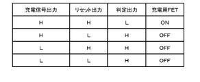
- the charging signal is HIGH or LOW, and as shown in the table of FIG. 2, it is determined whether or not the charging switch unit 2 can be charged in combination with the determination signal.
- a programmable microcomputer or the like can be preferably used as the charge control unit 20.
- the charge control unit 20 outputs a monitoring signal to the monitoring unit 30.
- the monitoring signal is, for example, a watchdog pulse.
- the watchdog pulse is output at a predetermined period T as shown in FIG. 3 when the microcomputer of the charge control unit 20 is normal.
- the microcomputer is abnormal, for example, the cycle becomes longer (T + ⁇ ) as shown in FIG. 4A or shorter (T- ⁇ ) as shown in FIG. 4B.
- the monitoring unit 30 monitors the monitoring signal, determines whether the monitoring signal is normal or abnormal, and outputs the determination result as a determination signal.
- the monitoring unit 30 is, for example, a watchdog timer IC that monitors the watchdog pulse, and determines whether it is a normal watchdog pulse as shown in FIG. 3 or an abnormal watchdog pulse as shown in FIGS. 4A and 4B. judge. In this way, the watch dock timer IC can be used to determine the abnormality of the charge control unit 20. (Judgment unit 40)
- the determination unit 40 instructs whether or not the charge switch unit 2 can operate based on the outputs of the charge control unit 20 and the monitoring unit 30.
- a NAND circuit can be preferably used for the determination unit 40.
- the determination circuit composed of the NAND circuit of FIG. 1 inputs the charge signal of the charge control unit 20 and the determination signal of the monitoring unit 30. When any of the inputs is LOW, this determination circuit outputs HIGH and forcibly turns off the charge switch unit 2. (Reset signal)
- the monitoring unit 30 may also output the determination signal to the charge control unit 20.
- the determination signal can be a reset signal for resetting the charge control unit 20. If the determination signal is abnormal, the charge control unit 20 resets the charge control unit 20. As a result, when an abnormality in the charge control unit 20 is detected by the monitoring unit 30, it is possible to reset the charge control unit 20 to eliminate the abnormal state. Further, the determination signal of the monitoring unit 30 can be shared with the reset signal of the charge control unit 20, which can be useful for recovery of the charge control unit 20 when an abnormality occurs.
- the judgment signal When used as a reset signal, it may be set to HIGH if it is normal and LOW if it is abnormal. In this case, the charge control unit 20 resets the charge control unit 20 when the reset signal is LOW.
- the determination unit 40 is configured to allow charging of the charge switch unit 2 only when the charge signal of the charge control unit 20 is HIGH and the reset signal of the monitoring unit 30 is HIGH. it can. As a result, by making a judgment not only by the charging signal by the charging control unit 20 but also by the judgment signal from the monitoring unit 30 of another member, it is possible to respond to an abnormality in the charging control unit, further improving safety and reliability. Is planned.
- the charge control unit 20 performs failure diagnosis in a state where the monitoring signal can be stably output after being reset by the determination signal, and outputs the charge signal when no abnormality is detected. In this way, since the charging signal is output after confirming that various abnormalities of the battery pack have not occurred, more reliable failure diagnosis is expected.
- the failure diagnosis performed by the charge control unit 20 here includes confirmation of the presence or absence of a short-circuit failure of the charge switch unit 2, abnormality check of the ROM for storing the program inside the microcomputer, and the like. (Switching unit 50)
- the switching unit 50 is connected between the output side of the determination unit 40 and the charging switch unit 2.
- the switching unit 50 forcibly shuts off the charging operation of the charging switch unit 2 when the determination unit 40 prohibits charging of the charging switch unit 2.
- the switching unit 50 of FIG. 1 inputs Vbat, which is the voltage of the secondary battery 1, and the output of the drive circuit 10, and switches between them based on the determination output from the determination unit 40.
- Vbat which is the voltage of the secondary battery 1
- the switching unit 50 outputs the output of the drive circuit 10 as it is.
- the determination output of the determination unit 40 is HIGH
- the Vbat voltage is output.
- This Vbat voltage becomes a forced OFF signal of the charging FET, whereby the charging switch unit 2 is forcibly turned off. In this way, the charging operation by the charging FET can be turned off in terms of hardware, and the charging path can be safely cut off until the battery pack 100 resumes the normal operation as described later. (Runaway monitoring function)
- the battery pack 100 of FIG. 1 it is possible to detect an abnormality in the charge control unit 20 to ensure the safety of charging.
- a conventional battery pack if the program of the microcomputer constituting the charge control unit 20 goes out of control, charging may not be stopped even if the charging voltage becomes high. In order to prevent this, it is conceivable to provide another microcomputer for duplication, but this method complicates the configuration and increases the cost. Therefore, in the present embodiment, by adding a cheaper and simpler monitoring unit 30, charging can be reliably stopped when an abnormality occurs in the charging control unit 20.
- the reset signal of this watchdog timer IC is high from low level before the microcomputer starts normally after the reset of the microcomputer and starts the proper control and protection operation.
- the microcomputer of the charge control unit 20 is operated according to a predetermined clock generated internally.
- the charge control unit 20 outputs a monitoring signal to the monitoring unit 30.
- the monitoring signal can be a watchdog pulse as described above.
- the watchdog pulse is output at a predetermined period T as shown in FIG. 3 when the microcomputer of the charge control unit 20 is normal.
- the microcomputer is abnormal, for example, the cycle becomes longer (T + ⁇ ) as shown in FIG. 4A or shorter (T- ⁇ ) as shown in FIG. 4B.
- the monitoring unit 30 is a watchdog timer IC (WDTIC) that monitors the watchdog pulse, which is the monitoring signal.
- the WDTIC determines whether the monitoring signal is normal or abnormal, and outputs the determination result as a determination signal. That is, it is determined whether it is a normal watchdog pulse as shown in FIG. 3 or an abnormal watchdog pulse as shown in FIGS. 4A and 4B. Then, the determination unit 40 instructs whether or not to charge the charge switch unit 2 based on the charge signal from the charge control unit 20 and the determination signal from the monitoring unit 30.
- the monitoring unit 30 detects the runaway of the program of the microcomputer, that is, the charge control unit 20, and outputs a reset signal. That is, it is assumed that the reset signal, which is a determination signal, changes from HIGH in the normal state to LOW. In response to this, the charge control unit 20 resets, that is, restarts the microcomputer according to the reset signal.
- the reset signal changes from the normal HIGH to LOW after a slight delay.
- the clock signal of the microcomputer which is periodically generated at the normal time, disappears.
- the charging signal emitted by the microcomputer switches from HIGH, that is, charging permission in the normal state, to LOW, that is, charging prohibition.
- the charging FET which is the charging switch unit 2
- charging is prohibited by receiving the charging signal of the microcomputer OFF (FIG. 5D), but charging is stopped immediately after receiving the determination result of the monitoring unit 30 without waiting for the charging signal to be OFF.
- the reaction speed is made faster and the safety is improved.
- the reset is released after the elapse of a predetermined period, and as shown in FIG. 5A, the reset signal returns from the LOW at the time of abnormality to the HIGH at the normal time.
- the reset microcomputer restarts after a lapse of a predetermined time, and the reset signal inside the microcomputer changes from LOW at the time of abnormality to HIGH at the normal time again as shown in FIG. 5B, and similarly as shown in FIG. 5C.
- the clock operation inside the microcomputer is also restarted.
- a failure diagnosis is performed after a stable period of oscillation accuracy. As described above, short-circuit failure determination of the charging FET, ROM check inside the microcomputer, etc.
- the determination unit 40 which is a NAND circuit, outputs a determination output when the determination output is abnormal because both the charge permission signal (FIG. 5D) and the determination signal (FIG. 5A) shown in the first line of FIG. 2 become HIGH.
- the HIGH is switched to the normal LOW, the charging FET is turned on as shown in FIG. 5E, and charging is started. In this way, the operation after the reset of the microcomputer is stable, and after it is determined that there is no failure, the charging of the secondary battery 1 is restarted.
- charging control is performed by determining whether or not charging is possible based on not only the charging signal from the charging control unit 20 but also the determination signal from the monitoring unit 30 that monitors the charging control unit 20. Even if an abnormality occurs in the unit 20, even if the charge control unit 20 continues to output the charge signal, the charge switch unit 2 can be reliably shut off by the determination signal from the monitoring unit 30. , The reliability and safety of charging the secondary battery 1 are improved. Further, when a program runaway in the microcomputer occurs, the charging path can be reliably cut off until the operation of the power supply device is restarted.
- safety is ensured during the period from when the reset by the watchdog timer IC is released until the microcomputer operates stably. Further, the safety can be further enhanced by diagnosing the presence or absence of a failure in the battery pack 100 before resuming the operation. On the contrary, in the conventional battery pack, the cutoff of the charging path is released at the same time as the reset is released, so that if there is a failure, a problem may occur due to charging. On the other hand, the battery pack and the battery pack can be used more safely by considering the safety after the microcomputer is reset.
- the present invention is not limited to the configuration in which monitoring is performed during charging, and the secondary battery may be monitored during charging and discharging.
- safety measures are required when an abnormality occurs in the secondary battery 1 as compared with discharging, so that the abnormality monitoring function of the secondary battery of the present invention is preferably exhibited.
- the charging / discharging control unit may be used instead of the charging control unit.
- the charge control unit may have a function of controlling the discharge current regardless of its name.
- the battery pack and its abnormality monitoring method according to the present invention are incorporated in a battery pack for driving an electric tool, an electric assist bicycle, an electric bike, an electric three-wheeled vehicle, an electric wheelchair, an electric cart, an electric cleaner, an electric blower, for example, these devices. It can be suitably applied to a battery management system, a charger prepared as a separate member, and the like. It can also be applied as a power source for electric devices other than electric devices driven by a motor, for example, various electric devices used indoors and outdoors such as a radio and a lighting device, a power source for transportation means, and an auxiliary power source.
Landscapes
- Engineering & Computer Science (AREA)
- Power Engineering (AREA)
- Manufacturing & Machinery (AREA)
- Chemical & Material Sciences (AREA)
- Chemical Kinetics & Catalysis (AREA)
- Electrochemistry (AREA)
- General Chemical & Material Sciences (AREA)
- Charge And Discharge Circuits For Batteries Or The Like (AREA)
- Secondary Cells (AREA)
Priority Applications (4)
| Application Number | Priority Date | Filing Date | Title |
|---|---|---|---|
| JP2021528151A JPWO2020262002A1 (zh) | 2019-06-27 | 2020-06-11 | |
| CN202080038315.9A CN113892221A (zh) | 2019-06-27 | 2020-06-11 | 电池组以及其异常监视方法 |
| EP20830674.6A EP3993205A4 (en) | 2019-06-27 | 2020-06-11 | BATTERY PACK AND ANOMALITY MONITORING PROCEDURE THEREOF |
| US17/619,647 US20220352729A1 (en) | 2019-06-27 | 2020-06-11 | Battery pack, and abnormality monitoring method for same |
Applications Claiming Priority (2)
| Application Number | Priority Date | Filing Date | Title |
|---|---|---|---|
| JP2019119647 | 2019-06-27 | ||
| JP2019-119647 | 2019-06-27 |
Publications (1)
| Publication Number | Publication Date |
|---|---|
| WO2020262002A1 true WO2020262002A1 (ja) | 2020-12-30 |
Family
ID=74060273
Family Applications (1)
| Application Number | Title | Priority Date | Filing Date |
|---|---|---|---|
| PCT/JP2020/022937 WO2020262002A1 (ja) | 2019-06-27 | 2020-06-11 | 電池パック及びその異常監視方法 |
Country Status (5)
| Country | Link |
|---|---|
| US (1) | US20220352729A1 (zh) |
| EP (1) | EP3993205A4 (zh) |
| JP (1) | JPWO2020262002A1 (zh) |
| CN (1) | CN113892221A (zh) |
| WO (1) | WO2020262002A1 (zh) |
Families Citing this family (1)
| Publication number | Priority date | Publication date | Assignee | Title |
|---|---|---|---|---|
| TW202401939A (zh) * | 2022-06-27 | 2024-01-01 | 新盛力科技股份有限公司 | 電池模組的保護電路 |
Citations (5)
| Publication number | Priority date | Publication date | Assignee | Title |
|---|---|---|---|---|
| JPH07141066A (ja) | 1993-06-18 | 1995-06-02 | Pfu Ltd | 電源制御方式 |
| JP2009261092A (ja) * | 2008-04-15 | 2009-11-05 | Makita Corp | 充電装置、電池パック、及び充電システム |
| JP2012227986A (ja) * | 2011-04-15 | 2012-11-15 | Sony Corp | 電池パック、電力システムおよび電動車両 |
| JP2015109741A (ja) * | 2013-12-04 | 2015-06-11 | 株式会社デンソー | 電池制御装置 |
| WO2016072002A1 (ja) * | 2014-11-07 | 2016-05-12 | 株式会社日立製作所 | 蓄電管理システム |
Family Cites Families (2)
| Publication number | Priority date | Publication date | Assignee | Title |
|---|---|---|---|---|
| JP2005160169A (ja) * | 2003-11-21 | 2005-06-16 | Texas Instr Japan Ltd | バッテリ保護回路 |
| US8865328B2 (en) * | 2010-06-09 | 2014-10-21 | Samsung Sdi Co., Ltd. | Battery protecting circuit, method of controlling the same, and battery pack |
-
2020
- 2020-06-11 WO PCT/JP2020/022937 patent/WO2020262002A1/ja active Application Filing
- 2020-06-11 CN CN202080038315.9A patent/CN113892221A/zh active Pending
- 2020-06-11 EP EP20830674.6A patent/EP3993205A4/en active Pending
- 2020-06-11 US US17/619,647 patent/US20220352729A1/en active Pending
- 2020-06-11 JP JP2021528151A patent/JPWO2020262002A1/ja active Pending
Patent Citations (6)
| Publication number | Priority date | Publication date | Assignee | Title |
|---|---|---|---|---|
| JPH07141066A (ja) | 1993-06-18 | 1995-06-02 | Pfu Ltd | 電源制御方式 |
| JP2009261092A (ja) * | 2008-04-15 | 2009-11-05 | Makita Corp | 充電装置、電池パック、及び充電システム |
| JP5284672B2 (ja) | 2008-04-15 | 2013-09-11 | 株式会社マキタ | 充電装置及び充電システム |
| JP2012227986A (ja) * | 2011-04-15 | 2012-11-15 | Sony Corp | 電池パック、電力システムおよび電動車両 |
| JP2015109741A (ja) * | 2013-12-04 | 2015-06-11 | 株式会社デンソー | 電池制御装置 |
| WO2016072002A1 (ja) * | 2014-11-07 | 2016-05-12 | 株式会社日立製作所 | 蓄電管理システム |
Non-Patent Citations (1)
| Title |
|---|
| See also references of EP3993205A4 |
Also Published As
| Publication number | Publication date |
|---|---|
| EP3993205A1 (en) | 2022-05-04 |
| JPWO2020262002A1 (zh) | 2020-12-30 |
| CN113892221A (zh) | 2022-01-04 |
| US20220352729A1 (en) | 2022-11-03 |
| EP3993205A4 (en) | 2022-08-31 |
Similar Documents
| Publication | Publication Date | Title |
|---|---|---|
| JP4556929B2 (ja) | 電動工具 | |
| JP5488877B2 (ja) | 電動工具 | |
| US20160090052A1 (en) | On-vehicle electrical storage apparatus | |
| JP4861245B2 (ja) | 二次電池充電システム | |
| JP2010130768A (ja) | バッテリシステム | |
| JP4744859B2 (ja) | 電池パック | |
| JP4785708B2 (ja) | パック電池の制御方法 | |
| JP2007115472A (ja) | 電池パック、充電器、充電システムおよび充電異常検出方法 | |
| WO2010047255A1 (ja) | 電池パックシステム | |
| JP2020530751A (ja) | メインバッテリー及びサブバッテリーを制御するための装置、バッテリーシステム及び方法 | |
| JP2010233358A (ja) | 電池保護回路、電池保護方法、電源装置およびプログラム | |
| JP2005192371A (ja) | 電源装置 | |
| JP5712357B2 (ja) | 電池パック | |
| JP5339961B2 (ja) | 電気自動車用バッテリ制御装置及びバッテリシステム | |
| JP6589948B2 (ja) | 電源装置 | |
| JP2010239860A (ja) | 電池パック及び充電器システム | |
| JP5397985B2 (ja) | 二次電池パック | |
| WO2020262002A1 (ja) | 電池パック及びその異常監視方法 | |
| JP4579124B2 (ja) | 電池パックおよびその充電方法 | |
| JP7049401B2 (ja) | モーションセンサを有する電池を再充電するシステム | |
| WO2017191818A1 (ja) | 電源装置 | |
| JP4435000B2 (ja) | 電池制御回路、該電池制御回路を備えた電子機器、充電制御プログラム、充電制御方法 | |
| JP2009044923A (ja) | 電源システム | |
| JP2010033773A (ja) | 電池パック、及び電池システム | |
| JP2014072975A (ja) | 充電装置 |
Legal Events
| Date | Code | Title | Description |
|---|---|---|---|
| 121 | Ep: the epo has been informed by wipo that ep was designated in this application |
Ref document number: 20830674 Country of ref document: EP Kind code of ref document: A1 |
|
| ENP | Entry into the national phase |
Ref document number: 2021528151 Country of ref document: JP Kind code of ref document: A |
|
| NENP | Non-entry into the national phase |
Ref country code: DE |
|
| WWE | Wipo information: entry into national phase |
Ref document number: 2020830674 Country of ref document: EP |
|
| ENP | Entry into the national phase |
Ref document number: 2020830674 Country of ref document: EP Effective date: 20220127 |