WO2020261940A1 - バッテリモジュール - Google Patents
バッテリモジュール Download PDFInfo
- Publication number
- WO2020261940A1 WO2020261940A1 PCT/JP2020/022339 JP2020022339W WO2020261940A1 WO 2020261940 A1 WO2020261940 A1 WO 2020261940A1 JP 2020022339 W JP2020022339 W JP 2020022339W WO 2020261940 A1 WO2020261940 A1 WO 2020261940A1
- Authority
- WO
- WIPO (PCT)
- Prior art keywords
- cell
- endothermic
- battery module
- heat
- aluminum hydroxide
- Prior art date
- Legal status (The legal status is an assumption and is not a legal conclusion. Google has not performed a legal analysis and makes no representation as to the accuracy of the status listed.)
- Ceased
Links
Images


Classifications
-
- H—ELECTRICITY
- H01—ELECTRIC ELEMENTS
- H01M—PROCESSES OR MEANS, e.g. BATTERIES, FOR THE DIRECT CONVERSION OF CHEMICAL ENERGY INTO ELECTRICAL ENERGY
- H01M10/00—Secondary cells; Manufacture thereof
- H01M10/60—Heating or cooling; Temperature control
- H01M10/65—Means for temperature control structurally associated with the cells
- H01M10/655—Solid structures for heat exchange or heat conduction
- H01M10/6554—Rods or plates
- H01M10/6555—Rods or plates arranged between the cells
-
- H—ELECTRICITY
- H01—ELECTRIC ELEMENTS
- H01M—PROCESSES OR MEANS, e.g. BATTERIES, FOR THE DIRECT CONVERSION OF CHEMICAL ENERGY INTO ELECTRICAL ENERGY
- H01M10/00—Secondary cells; Manufacture thereof
- H01M10/60—Heating or cooling; Temperature control
- H01M10/61—Types of temperature control
- H01M10/613—Cooling or keeping cold
-
- H—ELECTRICITY
- H01—ELECTRIC ELEMENTS
- H01M—PROCESSES OR MEANS, e.g. BATTERIES, FOR THE DIRECT CONVERSION OF CHEMICAL ENERGY INTO ELECTRICAL ENERGY
- H01M10/00—Secondary cells; Manufacture thereof
- H01M10/60—Heating or cooling; Temperature control
- H01M10/62—Heating or cooling; Temperature control specially adapted for specific applications
- H01M10/625—Vehicles
-
- H—ELECTRICITY
- H01—ELECTRIC ELEMENTS
- H01M—PROCESSES OR MEANS, e.g. BATTERIES, FOR THE DIRECT CONVERSION OF CHEMICAL ENERGY INTO ELECTRICAL ENERGY
- H01M10/00—Secondary cells; Manufacture thereof
- H01M10/60—Heating or cooling; Temperature control
- H01M10/65—Means for temperature control structurally associated with the cells
- H01M10/651—Means for temperature control structurally associated with the cells characterised by parameters specified by a numeric value or mathematical formula, e.g. ratios, sizes or concentrations
-
- H—ELECTRICITY
- H01—ELECTRIC ELEMENTS
- H01M—PROCESSES OR MEANS, e.g. BATTERIES, FOR THE DIRECT CONVERSION OF CHEMICAL ENERGY INTO ELECTRICAL ENERGY
- H01M10/00—Secondary cells; Manufacture thereof
- H01M10/60—Heating or cooling; Temperature control
- H01M10/65—Means for temperature control structurally associated with the cells
- H01M10/653—Means for temperature control structurally associated with the cells characterised by electrically insulating or thermally conductive materials
-
- H—ELECTRICITY
- H01—ELECTRIC ELEMENTS
- H01M—PROCESSES OR MEANS, e.g. BATTERIES, FOR THE DIRECT CONVERSION OF CHEMICAL ENERGY INTO ELECTRICAL ENERGY
- H01M10/00—Secondary cells; Manufacture thereof
- H01M10/60—Heating or cooling; Temperature control
- H01M10/65—Means for temperature control structurally associated with the cells
- H01M10/655—Solid structures for heat exchange or heat conduction
-
- H—ELECTRICITY
- H01—ELECTRIC ELEMENTS
- H01M—PROCESSES OR MEANS, e.g. BATTERIES, FOR THE DIRECT CONVERSION OF CHEMICAL ENERGY INTO ELECTRICAL ENERGY
- H01M10/00—Secondary cells; Manufacture thereof
- H01M10/60—Heating or cooling; Temperature control
- H01M10/65—Means for temperature control structurally associated with the cells
- H01M10/659—Means for temperature control structurally associated with the cells by heat storage or buffering, e.g. heat capacity or liquid-solid phase changes or transition
-
- H—ELECTRICITY
- H01—ELECTRIC ELEMENTS
- H01M—PROCESSES OR MEANS, e.g. BATTERIES, FOR THE DIRECT CONVERSION OF CHEMICAL ENERGY INTO ELECTRICAL ENERGY
- H01M10/00—Secondary cells; Manufacture thereof
- H01M10/60—Heating or cooling; Temperature control
- H01M10/64—Heating or cooling; Temperature control characterised by the shape of the cells
- H01M10/647—Prismatic or flat cells, e.g. pouch cells
-
- H—ELECTRICITY
- H01—ELECTRIC ELEMENTS
- H01M—PROCESSES OR MEANS, e.g. BATTERIES, FOR THE DIRECT CONVERSION OF CHEMICAL ENERGY INTO ELECTRICAL ENERGY
- H01M2220/00—Batteries for particular applications
- H01M2220/20—Batteries in motive systems, e.g. vehicle, ship, plane
-
- Y—GENERAL TAGGING OF NEW TECHNOLOGICAL DEVELOPMENTS; GENERAL TAGGING OF CROSS-SECTIONAL TECHNOLOGIES SPANNING OVER SEVERAL SECTIONS OF THE IPC; TECHNICAL SUBJECTS COVERED BY FORMER USPC CROSS-REFERENCE ART COLLECTIONS [XRACs] AND DIGESTS
- Y02—TECHNOLOGIES OR APPLICATIONS FOR MITIGATION OR ADAPTATION AGAINST CLIMATE CHANGE
- Y02E—REDUCTION OF GREENHOUSE GAS [GHG] EMISSIONS, RELATED TO ENERGY GENERATION, TRANSMISSION OR DISTRIBUTION
- Y02E60/00—Enabling technologies; Technologies with a potential or indirect contribution to GHG emissions mitigation
- Y02E60/10—Energy storage using batteries
Definitions
- the present invention relates to a battery module including a specific endothermic member.
- Electric vehicles have become widespread from the viewpoint of environmental issues.
- Electric vehicles are equipped with batteries such as lithium-ion secondary batteries.
- Batteries used in electric vehicles require high output and large capacity, and battery cells alone are not sufficient.
- Battery modules that combine multiple battery cells and battery packs that combine multiple battery modules are used. ing.
- Patent Document 1 contains at least one of a mineral powder and a flame retardant, starts an endothermic reaction at 100 to 1000 ° C., and the endothermic reaction causes a specific structural change.
- a runaway prevention sheet is described. It is described that the thermal runaway prevention sheet exhibits heat insulating performance and can prevent continuous thermal runaway of adjacent cells.
- an object of the present invention is to provide a battery module capable of effectively suppressing a temperature rise in the initial stage of abnormality and within a certain period from the occurrence of abnormality even when an abnormality occurs in the battery cell.
- the present invention provides the following [1] to [8].
- [1] A case, a plurality of cells arranged in the case having an energy density of 200 Wh / L or more, and at least one of the case and the cell and between the plurality of cells are provided with an endothermic member.
- the present invention it is possible to provide a battery module capable of effectively suppressing a temperature rise in the initial stage of abnormality and within a certain period from the occurrence of abnormality.
- a specific heat absorbing member is provided in at least one of a case, a plurality of cells arranged in the case having an energy density of 200 Wh / L or more, and between the case and the cells, and between the plurality of cells. It is a battery module provided.
- the endothermic amount Q from 150 ° C. to 350 ° C. of the endothermic member is 500 J / cm 3 or more, and the thermal conductivity ⁇ of the endothermic member is 0.8 W / mK or more.
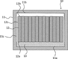
- FIG. 1 is a cross-sectional view schematically showing an example of arrangement of heat absorbing members of the battery module of the present invention.
- the battery module 10 includes a case 11, a plurality of cells 12 arranged in the case 11, and a heat absorbing member 13 provided between the case 11 and the cell 12.
- the cell 12 is a constituent unit of a lithium ion secondary battery or the like, and is generally composed of an exterior film and a battery element (not shown) enclosed in the exterior film. Examples of the battery element include a positive electrode, a negative electrode, a separator, and an electrolytic solution. As shown in FIG.
- the cell 12 is a flat body having a thickness thinner than the width, and the positive electrode 12a and the negative electrode 12b appear to the outside, and the flat surface 12c is thicker than the crimped end portion 12d. It is formed thick.
- the energy density of the cell 12 is 200 Wh / L or more. As described above, the high energy density makes it possible to reduce the size of the cell 12. On the other hand, there is a concern that the temperature tends to rise when an abnormality such as a short circuit occurs due to the high energy density. However, as will be described later, the endothermic member 13 has a constant endothermic amount Q and thermal conductivity ⁇ . Therefore, it is easy to suppress the temperature rise of the cell 12. The higher the energy density of the cell 12, the higher it is, but it is usually 700 WL / L or less.
- a plurality of cells 12 are laminated so that their planes are in contact with each other, and each cell 12 is arranged so that its longitudinal direction is the vertical direction of the case 11.
- the case 11 is a member that collectively covers the cell 12.
- the case 11 is made of a material that has strength to support a plurality of cells 12 and is not deformed by the heat generated from the cells 12, and it is preferable to use aluminum in consideration of the balance of strength, weight, heat resistance, and the like.
- the endothermic member 13 is provided between the lower surface 11a of the case and the lower end surface 12a of the cell 12.
- the heat absorbing member 13 can effectively suppress the temperature rise of the battery module in the initial stage of the abnormality and within a certain period from the occurrence of the abnormality when an abnormality occurs in the cell 12 due to an internal short circuit or damage from the outside. This is because the endothermic member 13 suppresses the temperature rise of the cell 12 and the thermal conductivity ⁇ is constant or higher because the endothermic amount Q when heated to 150 to 350 ° C. is constant or higher. It is presumed that the generated heat can be easily transferred to the case 11 effectively.
- the thermal conductivity ⁇ is above a certain level, in particular, the temperature rise at the initial stage of abnormality is suppressed, and the amount of heat absorbed Q is above a certain level, which is the continuous temperature during the initial stage of abnormality and the occurrence of the abnormality. It is speculated that the rise is suppressed.
- the mode in which the heat absorbing member 13 is provided between the lower surface 11a of the case 11 and the lower end surface 12a of the cell 12 is shown, but the arrangement of the heat absorbing member 13 is not limited to this mode. It may be provided in at least one space between an arbitrary surface of the case 11 and a surface of the cell 12 adjacent to this surface.
- the endothermic member 13 may be provided between the side surface 11c of the case and the eccentric plane 12c of the cell 12, between the upper surface 11b of the case and the upper end surface 12b of the cell 12.
- the endothermic member 13 may be provided in all the spaces between all the surfaces of the case 11 and the surfaces of the cells 12 adjacent to the surfaces (that is, the entire space inside the case 11), as shown in FIG.
- the endothermic member 13 may be arranged so as to wrap the entire plurality of cells 12. In this case, the heat generated from the cell 12 can be reduced more effectively.
- the heat absorbing member 13 is provided between the case 11 and the cell 12, but as shown in FIG. 4, the heat absorbing member 13 is placed between the plurality of cells 12 (between cells 14). It may be provided in.
- the endothermic member 13 can suppress the temperature rise of the cell 12 in which the abnormality has occurred, and the heat transfer at a high temperature to the adjacent cell 12 is less likely to occur, so that the spread of the abnormality can be suppressed. As a result, the temperature rise can be effectively suppressed in the initial stage of abnormality and in a certain period from the occurrence of abnormality.
- the heat absorbing member 13 may be provided between the case 11 and the cell 12 and may be provided between the plurality of cells 12.
- the endothermic member 13 is provided between the plurality of cells 12, all the surfaces of the case 11, and all the spaces between the surfaces of the cells 12 adjacent to the surfaces (in other words, the case).
- the endothermic member 13 is provided in all the spaces inside the 11), and the temperature rise of the cell 12 can be suppressed particularly effectively.
- the cell 12 describes a laminated cell using an exterior film, but a square cell or a cylindrical cell may be used in addition to the laminated cell.
- FIG. 1 and the like a mode in which a plurality of cells 12 are contacted and laminated is shown, but a functional member such as an absorbent material or a cooling fin may be provided between the cells 12 and the cell 12.
- a functional member such as an absorbent material or a cooling fin may be provided between the cells 12 and the cell 12.
- a sheet-shaped absorbent material 15 may be provided between the cells 12.
- the shock absorbing property can be improved and the occurrence of abnormalities in the cell 12 due to an external shock or the like can be reduced.
- a sub-module in which a plurality of cells 12 are laminated preferably a sub-module in which two cells 12 are laminated may be produced, and a heat absorbing material 15 may be provided between the sub-modules.
- Specific examples of the absorbent material 15 include a foam and a low-hardness rubber. Only one absorbent material 15 may be provided, or two or more absorbent materials 15 may be provided.
- the absorbing material 15 and the heat absorbing member 13 are arranged side by side between the cell 12 and the cell 12, or the heat absorbing member 13 is arranged between the absorbing material 15 and the cell 12.
- the absorbent material 15 and the heat absorbing member 13 are arranged side by side between the cell 12 and the cell 12, the heat absorbing member 13 is arranged at a place where there is a high risk of damage, and the absorbent 15 is arranged at another portion.
- an absorbent 15 is arranged near the center of the cell 12, and an endothermic member 13 is arranged near the outer edge and corners of the cell 12.
- a cooling fin 16 may be provided between the cell 12 and the cell 12.
- the cooling fin 16 is a member provided with a sheet and locking portions along the longitudinal direction at both ends of the sheet, and has an H-shaped cross section.
- a submodule in which a plurality of cells 12 are laminated preferably a submodule in which two cells 12 are laminated may be produced, and a cooling fin 16 may be provided between the submodules.
- the cooling fin 16 is preferably made of metal, more preferably made of aluminum. The cooling fins 16 make it easier to suppress the temperature rise of the cell 12. Only one cooling fin 16 may be provided, or two or more cooling fins 16 may be provided.
- a heat-dissipating adhesive or a heat-dissipating sheet may be provided between the cooling fins 16 and the cell 12.
- the endothermic member 13 it is preferable to arrange the endothermic member 13 between the cooling fins 16 and the cell 12.
- the heat generated in the cell 12 is effectively cooled by the endothermic member 13 and the cooling fins 16.
- the heat generated in the cell 12 is transmitted to the case surface through the locking portions of the heat absorbing member 13 and the cooling fin 16, and is more effectively dissipated and cooled.
- the structure of the cooling fin 16 is not limited to the above aspect.
- the endothermic member in the present invention has an endothermic amount Q of 500 J / cm 3 or more from 150 ° C. to 350 ° C.
- the endothermic amount Q is the amount of heat absorbed from 150 ° C. to 350 ° C. when the heat absorbing member is heated at a constant heating rate. If the heat absorption amount Q is less than 500 J / cm 3 , it becomes difficult to suppress the temperature rise of the battery module.
- Endothermic amount Q is preferably 1000 J / cm 3 or more, more preferably 1500 J / cm 3 or more, further preferably 2000J / cm 3 or more. The higher the heat absorption amount Q, the better, but usually it is 4000 J / cm 3 or less.
- the endothermic amount Q of the heat absorbing member can be calculated from the endothermic amount Qf (J / cm 3 ) of the filler contained in the heat absorbing member, which will be described later, and the volume ratio of the filler in the heat absorbing member.
- the heat absorption amount Qf of the filler is the heat absorption amount of the filler from 150 ° C. to 350 ° C.
- the heat absorption amount Qf of the filler is determined by TG-DTA measurement.
- the heat absorption amount Qf can be measured by a TG-DTA device, and the measurement conditions are as follows: using an aluminum pan of ⁇ 5 mm, in a nitrogen atmosphere (flow rate 50 ml / min), from 25 ° C. to a temperature rise rate of 5 ° C./min. It shall be measured. Further, when it is difficult to measure the endothermic amount Qf of the filler, the endothermic amount Q of the heat absorbing member can be directly measured by TG-DTA.
- a test piece of a disk-shaped heat absorbing member having a diameter of 5 mm and a thickness of 2 mm is prepared, and this test piece is arranged so as to be in close contact with the bottom surface of the aluminum pan having a diameter of 5 mm, and is placed in a nitrogen atmosphere (flow rate 50 ml / min). ), The temperature rise rate is 5 ° C./min from 25 ° C.
- the thermal conductivity ⁇ of the endothermic member is 0.8 W / mK or more. If the thermal conductivity is less than 0.8 W / mK, heat transfer from the endothermic member to the case or the like is unlikely to occur, and therefore, the temperature rise of the battery module in which the abnormality has occurred tends to be large.
- the thermal conductivity ⁇ of the endothermic member is preferably 1.0 W / mK or more, and more preferably 1.5 W / mK or more.
- the upper limit of the thermal conductivity is preferably 4.0 W / mK or less, more preferably 3.4 W / mK or less, and further preferably 2.8 W / mK or less.
- the thermal conductivity ⁇ can be measured by a method according to ASTM D5470-06. Specifically, a sample having a thickness within the range of 0.5 mm to 5.0 mm (preferably 1.0 mm to 3.0 mm) is prepared for the endothermic member, and the thermal resistance is measured at three different thicknesses. Calculate the thermal conductivity. As the samples having different thicknesses, samples having different thicknesses may be prepared separately, or a single sample may be measured by changing the compression ratio.
- the product ( ⁇ ⁇ Q) of the thermal conductivity ⁇ and the heat absorption amount Q is preferably 1000 W ⁇ J / mK ⁇ cm 3 or more, more preferably 2000 W ⁇ J / mK ⁇ cm 3 or more, and 3000 W. -J / mK ⁇ cm 3 or more is more preferable, and 16000 W ⁇ J / mK ⁇ cm 3 or less is preferable.
- both the endothermic amount Q and the thermal conductivity ⁇ of the heat absorbing member are large values, the temperature rise of the battery module can be suppressed more effectively.
- the large amount of heat absorption Q reduces the temperature of the cell, and the large thermal conductivity ⁇ makes it easier to transfer the heat generated from the cell to the case, etc. Therefore, due to the synergistic effect of each of these actions, It is considered that the temperature rise of the battery module can be effectively suppressed.
- the endothermic member may be provided so that the endothermic amount Qs per unit area is preferably 50 J / cm 2 or more, more preferably 100 J / cm 2 or more, and further preferably 200 J / cm 2 or more with respect to the cell surface. ..
- the upper limit of the heat absorption amount Qs is not particularly limited, but is, for example, 1000 J / cm 2 .
- the endothermic member of the present invention contains a resin and a filler. Each component of these heat absorbing members will be described below.
- the resin contained in the endothermic member is not particularly limited, and examples thereof include rubber and elastomer.
- examples of the rubber include silicone rubber, acrylic rubber, nitrile rubber, isoprene rubber, urethane rubber, ethylene propylene rubber, styrene-butadiene rubber, butadiene rubber, fluororubber, and butyl rubber. When these rubbers are used, they may be crosslinked or may remain uncrosslinked (ie, uncured).
- thermoplastic elastomer such as a polyester-based thermoplastic elastomer or a polyurethane-based thermoplastic elastomer, or a thermosetting elastomer formed by curing a mixed liquid polymer composition composed of a main agent and a curing agent is also used. It is possible. For example, a polyurethane-based elastomer formed by curing a polymer composition containing a polymer having a hydroxyl group and an isocyanate can be exemplified.
- the resin contained in the endothermic member is preferably silicone rubber.
- the silicone rubber is preferably formed from liquid silicone, and specifically, the endothermic member is preferably formed from a heat absorbing composition containing liquid silicone and a filler.
- the liquid silicone may be a non-curable silicone or a reaction-curable silicone, but it is preferable to use a reaction-curable silicone.
- the liquid state means that it is in a liquid state at room temperature (25 ° C.).
- reaction-curable silicone examples include addition reaction-curable silicone, radical reaction-curable silicone, condensation reaction-curable silicone, ultraviolet or electron beam-curable silicone, and moisture-curable silicone.
- the reaction-curable silicone is preferably an addition-reaction-curable silicone.
- the addition reaction curable silicone those containing an alkenyl group-containing organopolysiloxane (main agent) and hydrogen organopolysiloxane (curing agent) are more preferable.
- the content of the silicone rubber based on the total amount of resin contained in the endothermic member is preferably 80% by mass or more, more preferably 95% by mass or more, and further preferably 100% by mass.
- the endothermic member in the present invention contains a filler.
- the filler is not particularly limited as long as the heat absorption amount Q and the thermal conductivity ⁇ of the heat absorbing member are within the above-mentioned predetermined ranges. Although it depends on the type of filler described later, the content of the filler is preferably 50 to 1500 parts by mass, and more preferably 100 to 1000 parts by mass with respect to 100 parts by mass of the resin.
- the filler examples include aluminum oxide, boron nitride, aluminum nitride, silicon carbide, aluminum hydroxide, magnesium hydroxide and the like.
- the filler preferably contains at least aluminum hydroxide from the viewpoint of easily adjusting the endothermic amount Q and the thermal conductivity ⁇ of the heat absorbing member within a desired range.
- aluminum hydroxide may be used alone, but two or more types of water having different average particle diameters are used to increase the endothermic amount Q and the thermal conductivity ⁇ by increasing the filling amount in the heat absorbing member. It is preferable to use aluminum oxide.
- the aluminum hydroxide preferably contains small particle size aluminum hydroxide having an average particle size of 2 ⁇ m or less and large particle size aluminum hydroxide having an average particle size of more than 2 ⁇ m.
- the small particle size aluminum hydroxide preferably has an average particle size of 1 ⁇ m or less.
- the average particle size can be measured with an electron microscope or the like.
- the amount of small particle size aluminum hydroxide with respect to large particle size aluminum hydroxide is 0.1 to 2 from the viewpoint of increasing the filling amount in the heat absorbing member. It is preferably 0.1 to 0.8, more preferably 0.2 to 0.5.
- the above-mentioned large particle size aluminum hydroxide includes a first large particle size aluminum hydroxide having an average particle size of more than 2 ⁇ m and 20 ⁇ m or less and an average particle size of more than 20 ⁇ m and 100 ⁇ m or less from the viewpoint of increasing the filling amount in the heat absorbing member. It preferably contains a second large particle size aluminum hydroxide.
- the amount of the first large particle size aluminum hydroxide with respect to the second large particle size aluminum hydroxide is 0.1 to 2. It is preferably 0.2 to 1.5, more preferably 0.3 to 1, and even more preferably 0.3 to 1.
- the amount of aluminum hydroxide with respect to 100 parts by mass of the resin is preferably 50 parts by mass or more, more preferably 100 parts by mass or more, still more preferably 300 parts by mass. More than parts, more preferably 500 parts by mass or more, and preferably 1500 parts by mass or less.
- the content of aluminum hydroxide based on the total amount of the filler is preferably 10% by mass or more, more preferably 70% by mass or more, and further preferably 100% by mass from the viewpoint of increasing the heat absorption amount Q and the thermal conductivity ⁇ . ..
- the filler preferably contains aluminum hydroxide and aluminum oxide from the viewpoint of adjusting the thermal conductivity ⁇ to be higher.
- the filler Preferably composed of aluminum hydroxide and aluminum oxide only.
- the amount of aluminum hydroxide (aluminum hydroxide / aluminum oxide) with respect to aluminum oxide may be preferably in the range of 0.05 to 7, more preferably 0.1 to 5.
- the average particle size of aluminum oxide is not particularly limited, but is preferably 0.5 to 150 ⁇ m, and more preferably 1 to 100 ⁇ m.
- the above-mentioned filler may be surface-treated with a silane coupling agent or the like.
- a silane coupling agent known ones are used without particular limitation, and for example, dimethyldimethoxysilane, 3-acryloxypropyltrimethoxysilane, 3-methacryloxypropyltrimethoxysilane, vinyltrimethoxysilane, n-decyltri.
- the endothermic member is preferably formed of an endothermic composition containing a resin and a filler, and as described above, is preferably formed of an endothermic composition containing a liquid silicone and a filler.
- the amount of the filler for the liquid silicone is the same as the amount of the filler for the resin described above.
- the endothermic composition may contain the above-mentioned silane coupling agent, and may contain additives such as a dispersant, a flame retardant, a plasticizer, a curing retarder, an antioxidant, a colorant, and a catalyst.
- a battery pack can be formed by using a plurality of battery modules provided with the above-mentioned heat absorbing members.
- FIG. 8 is an explanatory diagram showing an example of a state in which the battery pack is assembled.
- the battery pack 20 includes a plurality of battery modules 10, a battery pack housing 19 for storing the battery modules 10, and a heat-dissipating material 18 provided between the battery module 10 and the battery pack housing 19.
- the battery module 10 is fixed to the battery pack housing 19 via the heat radiating material 18.
- the battery pack housing 19 can be formed of the same material as the case 11 described above. In the battery pack 20, the heat generated from the battery module 10 can be released to the battery pack housing 19 via the heat radiating material 18.
- the heat generated in the cell 12 is transferred to the endothermic member 13, the case 11, the heat-dissipating material 18, and the battery pack housing 19, so that heat can be efficiently dissipated to the outside.
- the heat-dissipating material 18 a known material such as silicone rubber containing a heat conductive filler such as aluminum oxide, aluminum nitride, or boron nitride can be used, but the endothermic member of the present invention may be used.
- the heat absorbing member is used, the temperature can be effectively reduced because the heat absorbing amount Q and the thermal conductivity ⁇ are equal to or higher than a certain level.
- evaluation was performed by the following method.
- the thermal conductivity of the endothermic member was determined by a method of measuring the thermal resistance using a measuring device compliant with ASTM D5470-06. Using a heat absorbing member with a thickness of 1.0 mm, it is compressed so that the compression ratio is 10% (thickness 0.9 mm), 20% (thickness 0.8 mm), and 30% (thickness 0.7 mm). The thermal resistance at each compression ratio (10 to 30%) was measured. For these three thermal resistance values, a graph of thickness on the horizontal axis and thermal resistance value on the vertical axis was created, and approximate straight lines of three points were obtained by the least squares method. Then, the slope of the approximate straight line becomes the thermal conductivity. The thermal resistance was measured at 80 ° C. and was carried out by LW-9389 manufactured by Long Win Science and Technology Corporation.
- the endothermic amount Q of the heat absorbing member was calculated from the value of Qf after determining the endothermic amount Qf of the filler contained in the heat absorbing member from 150 ° C. to 350 ° C.
- the heat absorption amount Qf was measured by a TG-DTA device (manufactured by Shimadzu Corporation, a differential thermal / thermogravimetric simultaneous measurement device "DTG-60").
- the amount of heat absorbed from 150 to 350 ° C. was determined by heating from 25 ° C. to 600 ° C. at a heating rate of 5 ° C./min in a nitrogen atmosphere.
- Example 1 (1) Preparation of heat absorbing composition 100 parts by mass of addition reaction curable silicone composed of main agent and curing agent, 150 parts by mass of aluminum hydroxide having an average particle size of 1 ⁇ m, 150 parts by mass of aluminum hydroxide having an average particle size of 10 ⁇ m, average A heat absorbing composition consisting of 300 parts by mass of aluminum hydroxide having a particle size of 54 ⁇ m and 1 part by mass of a silane coupling agent was prepared.
- Both sides of the cell provided with the endothermic member produced in this way are sandwiched between two aluminum plates (125 mm ⁇ 210 mm ⁇ 10 mm) corresponding to adjacent cells, and the ends are bolted. It was fixed with and used as a sample for a nail piercing test. The temperature change in the nail piercing test of the sample was measured. For the temperature change, the thermocouple was placed "between the cell and the endothermic member" in order to measure the temperature of the cell in which the abnormality occurred, and the "maximum cell temperature up to the lapse of 50 seconds" was measured. Further, another thermocouple was placed "between the aluminum plate and the endothermic member" corresponding to the surface of the cell in contact with the adjacent cell, and the external temperature was measured after 300 seconds had elapsed.
- thermocouple arranged between the cell and the endothermic member is as follows.
- this fire resistance test it is known that the temperature of the cell tends to rise sharply immediately after the nail is pierced, and then the temperature tends to fall. Since this initial temperature rise is extremely fast, the temperature outside the heat absorbing member is affected by the heat absorption amount and heat conductivity of the heat absorbing member in addition to the time difference in heat transfer, so a temperature lower than the actual maximum temperature is detected. It is necessary to measure the temperature inside the heat absorbing member because the temperature of the abnormal cell cannot be accurately grasped.
- the initial temperature rise of the abnormal cell can be suppressed to a low level, it can be expected that the influence on the surroundings due to heat conduction through a path through which it is difficult to interpose a heat absorbing member such as a bus bar can be reduced.
- the reason why the "external temperature after 300 seconds" was measured with a thermocouple placed between the aluminum plate and the endothermic member is that after about 300 seconds, the temperature becomes stable and the inside of the endothermic member.
- the temperature difference from the outside becomes a predetermined temperature affected by thermal conductivity, endothermic amount, and the like.
- the nail piercing test was performed by piercing a nail ( ⁇ 6 mm, tip angle 30 ° C.) from the side surface of the cell (a surface having an area of 70 mm ⁇ 125 mm) to the center of the cell at a speed of 20 mm / sec.
- the maximum cell temperature from 50 seconds after the nail was pierced into the cell and the external temperature after 300 seconds were measured by a thermocouple and evaluated according to the following criteria.
- the results are shown in Table 2.
- Maximum cell temperature up to 50 seconds is 300 ° C Super 350 ° C or less D .
- Maximum cell temperature up to after 50 seconds exceeds 350 ° C ⁇ Full-year temperature rise suppression effect >> A ... External temperature after 300 seconds is 270 ° C or less B .
- External temperature after 300 seconds is over 270 ° C and below 300 ° C D .
- External temperature after 300 seconds is over 300 ° C ⁇ Comprehensive evaluation >> A ...
- the initial and full-year results are both A B ...
- One of the initial and full year results is B, the other is A or B C ...
- At least one of the initial and full-year results is C, the other is any of A, B, C D ...
- At least one of the initial and full-year results is D
- Examples 2 to 5 Comparative Example 3
- An endothermic composition was prepared in the same manner as in Example 1 except that the composition of the endothermic composition was changed as shown in Table 1, and a nail piercing test was performed. The results are shown in Table 2.
- Example 1 The nail piercing test was carried out in the same manner as in Example 1 except that airgel (thickness 10 mm, thermal conductivity 0.017 W / mK) was used instead of the endothermic composition used in Example 1. The results are shown in Table 2.
- Example 2 In Example 1, a nail piercing test was performed in the same manner as in Example 1 except that the endothermic composition was not used.
- Example 2 having less than 3, the overall evaluation is "C", and it can be seen that the temperature rise of the cell is further suppressed by adjusting the heat absorption amount Q to a suitable range.
- the composition of the endothermic member is the same as that of Example 1 and Example 3, but the amount of heat absorption Qs per unit area is different. That is, it can be seen that in Example 1, Qs is a higher value, which is in a suitable range, the overall evaluation is high, and the temperature rise of the cell is easily suppressed.
- Battery module 11 Case 11a Lower surface 11b Upper surface 12 Cell 12a Positive electrode 12b Negative electrode 12c Eccentric plane 12d End 13 Heat absorbing member 14 Between cells 15 Absorbent material 16 Cooling fin 18 Heat dissipation material 19 Battery pack housing 20 Battery pack
Landscapes
- Engineering & Computer Science (AREA)
- Manufacturing & Machinery (AREA)
- Chemical & Material Sciences (AREA)
- Chemical Kinetics & Catalysis (AREA)
- Electrochemistry (AREA)
- General Chemical & Material Sciences (AREA)
- Physics & Mathematics (AREA)
- Algebra (AREA)
- General Physics & Mathematics (AREA)
- Mathematical Analysis (AREA)
- Mathematical Optimization (AREA)
- Pure & Applied Mathematics (AREA)
- Secondary Cells (AREA)
- Battery Mounting, Suspending (AREA)
- Locating Faults (AREA)
Priority Applications (7)
| Application Number | Priority Date | Filing Date | Title |
|---|---|---|---|
| CN202080040386.2A CN113906611B (zh) | 2019-06-27 | 2020-06-05 | 电池模块 |
| US17/615,703 US20220238939A1 (en) | 2019-06-27 | 2020-06-05 | Battery module |
| JP2020566004A JP7001297B2 (ja) | 2019-06-27 | 2020-06-05 | バッテリモジュール |
| CN202411372599.1A CN119208825A (zh) | 2019-06-27 | 2020-06-05 | 电池模块 |
| KR1020217039297A KR20220022900A (ko) | 2019-06-27 | 2020-06-05 | 배터리 모듈 |
| EP20832261.0A EP3993083A4 (en) | 2019-06-27 | 2020-06-05 | BATTERY MODULE |
| JP2021205395A JP7513236B2 (ja) | 2019-06-27 | 2021-12-17 | バッテリモジュール |
Applications Claiming Priority (2)
| Application Number | Priority Date | Filing Date | Title |
|---|---|---|---|
| JP2019119389 | 2019-06-27 | ||
| JP2019-119389 | 2019-06-27 |
Publications (1)
| Publication Number | Publication Date |
|---|---|
| WO2020261940A1 true WO2020261940A1 (ja) | 2020-12-30 |
Family
ID=74061225
Family Applications (1)
| Application Number | Title | Priority Date | Filing Date |
|---|---|---|---|
| PCT/JP2020/022339 Ceased WO2020261940A1 (ja) | 2019-06-27 | 2020-06-05 | バッテリモジュール |
Country Status (6)
| Country | Link |
|---|---|
| US (1) | US20220238939A1 (https=) |
| EP (1) | EP3993083A4 (https=) |
| JP (2) | JP7001297B2 (https=) |
| KR (1) | KR20220022900A (https=) |
| CN (2) | CN119208825A (https=) |
| WO (1) | WO2020261940A1 (https=) |
Cited By (9)
| Publication number | Priority date | Publication date | Assignee | Title |
|---|---|---|---|---|
| WO2022163206A1 (ja) * | 2021-01-29 | 2022-08-04 | 積水ポリマテック株式会社 | バッテリモジュール |
| WO2022210368A1 (ja) * | 2021-03-29 | 2022-10-06 | 積水化学工業株式会社 | 積層体 |
| WO2023032741A1 (ja) * | 2021-08-31 | 2023-03-09 | 日本ゼオン株式会社 | バッテリーモジュール用シート及びバッテリーモジュール |
| CN116822999A (zh) * | 2023-08-31 | 2023-09-29 | 中国石油大学(华东) | 成品油管道混油界面后行油品监测密度预测方法及系统 |
| JP2024510686A (ja) * | 2022-02-25 | 2024-03-11 | 寧徳時代新能源科技股▲分▼有限公司 | 電池、電力消費機器、電池の製造方法及び機器 |
| JP2024533031A (ja) * | 2022-01-10 | 2024-09-12 | ワッカー ケミー アクチエンゲゼルシャフト | ポリシロキサン組成物 |
| JP2025507970A (ja) * | 2022-03-18 | 2025-03-21 | エルジー エナジー ソリューション リミテッド | 吸熱体及びそれを含む電池モジュール |
| JP2025536363A (ja) * | 2022-10-26 | 2025-11-05 | ワッカー ケミー アクチエンゲゼルシャフト | 電池モジュール用シリコーン系熱絶縁材料 |
| JP7829107B1 (ja) | 2024-01-19 | 2026-03-12 | エルジー エナジー ソリューション リミテッド | 二次電池用吸熱パッドおよびそれを含むバッテリパック |
Families Citing this family (2)
| Publication number | Priority date | Publication date | Assignee | Title |
|---|---|---|---|---|
| JP2023171019A (ja) * | 2022-05-20 | 2023-12-01 | 株式会社フコク | 2次電池用シリコーンゴム部材 |
| KR20240057181A (ko) * | 2022-10-24 | 2024-05-02 | 에스케이온 주식회사 | 방화벽을 구비하는 배터리 모듈 |
Citations (3)
| Publication number | Priority date | Publication date | Assignee | Title |
|---|---|---|---|---|
| JP2010123850A (ja) * | 2008-11-21 | 2010-06-03 | Asahi Kasei E-Materials Corp | 熱伝導シート |
| WO2017125985A1 (ja) * | 2016-01-21 | 2017-07-27 | パナソニックIpマネジメント株式会社 | 電池モジュール |
| WO2019058937A1 (ja) * | 2017-09-22 | 2019-03-28 | パナソニックIpマネジメント株式会社 | 電池モジュール |
Family Cites Families (6)
| Publication number | Priority date | Publication date | Assignee | Title |
|---|---|---|---|---|
| JP2010272430A (ja) * | 2009-05-22 | 2010-12-02 | Sanyo Electric Co Ltd | 車両用のバッテリシステム |
| DE102012109500A1 (de) * | 2012-10-05 | 2014-04-10 | Dr. Neidlinger Holding Gmbh | Wärmeableitendes Polymer und Harzzusammensetzungen zur Herstellung desselben |
| DE102015219280A1 (de) * | 2015-10-06 | 2017-04-06 | Robert Bosch Gmbh | Batteriesystem mit Vergussmasse |
| CN110431710B (zh) * | 2017-03-22 | 2023-04-04 | 积水保力马科技株式会社 | 电池模块及电池组 |
| JP6885791B2 (ja) | 2017-06-05 | 2021-06-16 | 積水化学工業株式会社 | 熱暴走防止シート |
| US12230820B2 (en) * | 2019-01-09 | 2025-02-18 | Byd Company Limited | Power battery pack and electric vehicle |
-
2020
- 2020-06-05 WO PCT/JP2020/022339 patent/WO2020261940A1/ja not_active Ceased
- 2020-06-05 EP EP20832261.0A patent/EP3993083A4/en active Pending
- 2020-06-05 JP JP2020566004A patent/JP7001297B2/ja active Active
- 2020-06-05 CN CN202411372599.1A patent/CN119208825A/zh active Pending
- 2020-06-05 KR KR1020217039297A patent/KR20220022900A/ko active Pending
- 2020-06-05 US US17/615,703 patent/US20220238939A1/en active Pending
- 2020-06-05 CN CN202080040386.2A patent/CN113906611B/zh active Active
-
2021
- 2021-12-17 JP JP2021205395A patent/JP7513236B2/ja active Active
Patent Citations (3)
| Publication number | Priority date | Publication date | Assignee | Title |
|---|---|---|---|---|
| JP2010123850A (ja) * | 2008-11-21 | 2010-06-03 | Asahi Kasei E-Materials Corp | 熱伝導シート |
| WO2017125985A1 (ja) * | 2016-01-21 | 2017-07-27 | パナソニックIpマネジメント株式会社 | 電池モジュール |
| WO2019058937A1 (ja) * | 2017-09-22 | 2019-03-28 | パナソニックIpマネジメント株式会社 | 電池モジュール |
Non-Patent Citations (1)
| Title |
|---|
| See also references of EP3993083A4 * |
Cited By (14)
| Publication number | Priority date | Publication date | Assignee | Title |
|---|---|---|---|---|
| WO2022163206A1 (ja) * | 2021-01-29 | 2022-08-04 | 積水ポリマテック株式会社 | バッテリモジュール |
| JPWO2022163206A1 (https=) * | 2021-01-29 | 2022-08-04 | ||
| WO2022210368A1 (ja) * | 2021-03-29 | 2022-10-06 | 積水化学工業株式会社 | 積層体 |
| WO2023032741A1 (ja) * | 2021-08-31 | 2023-03-09 | 日本ゼオン株式会社 | バッテリーモジュール用シート及びバッテリーモジュール |
| JP7760701B2 (ja) | 2022-01-10 | 2025-10-27 | ワッカー ケミー アクチエンゲゼルシャフト | ポリシロキサン組成物 |
| JP2024533031A (ja) * | 2022-01-10 | 2024-09-12 | ワッカー ケミー アクチエンゲゼルシャフト | ポリシロキサン組成物 |
| JP2024510686A (ja) * | 2022-02-25 | 2024-03-11 | 寧徳時代新能源科技股▲分▼有限公司 | 電池、電力消費機器、電池の製造方法及び機器 |
| JP7590429B2 (ja) | 2022-02-25 | 2024-11-26 | 香港時代新能源科技有限公司 | 電池、電力消費機器、電池の製造方法及び機器 |
| JP2025507970A (ja) * | 2022-03-18 | 2025-03-21 | エルジー エナジー ソリューション リミテッド | 吸熱体及びそれを含む電池モジュール |
| JP2025536363A (ja) * | 2022-10-26 | 2025-11-05 | ワッカー ケミー アクチエンゲゼルシャフト | 電池モジュール用シリコーン系熱絶縁材料 |
| CN116822999B (zh) * | 2023-08-31 | 2023-12-05 | 中国石油大学(华东) | 成品油管道混油界面后行油品监测密度预测方法及系统 |
| CN116822999A (zh) * | 2023-08-31 | 2023-09-29 | 中国石油大学(华东) | 成品油管道混油界面后行油品监测密度预测方法及系统 |
| JP7829107B1 (ja) | 2024-01-19 | 2026-03-12 | エルジー エナジー ソリューション リミテッド | 二次電池用吸熱パッドおよびそれを含むバッテリパック |
| JP2026509617A (ja) * | 2024-01-19 | 2026-03-23 | エルジー エナジー ソリューション リミテッド | 二次電池用吸熱パッドおよびそれを含むバッテリパック |
Also Published As
| Publication number | Publication date |
|---|---|
| JP2022027981A (ja) | 2022-02-14 |
| JP7513236B2 (ja) | 2024-07-09 |
| US20220238939A1 (en) | 2022-07-28 |
| CN113906611A (zh) | 2022-01-07 |
| CN119208825A (zh) | 2024-12-27 |
| CN113906611B (zh) | 2024-10-25 |
| KR20220022900A (ko) | 2022-02-28 |
| EP3993083A4 (en) | 2024-10-23 |
| JP7001297B2 (ja) | 2022-01-19 |
| EP3993083A1 (en) | 2022-05-04 |
| JPWO2020261940A1 (ja) | 2021-09-13 |
Similar Documents
| Publication | Publication Date | Title |
|---|---|---|
| JP7001297B2 (ja) | バッテリモジュール | |
| US8518574B1 (en) | Heat control pouch for battery cell module and battery cell module having the same | |
| EP3032607B1 (en) | Battery module | |
| JP6293451B2 (ja) | 環境親和型車両のバッテリーモジュール間接冷却装置 | |
| KR101470072B1 (ko) | 배터리 셀 모듈용 열 제어 플레이트 및 이를 갖는 배터리 셀 모듈 | |
| KR200479460Y1 (ko) | 복합재 열 확산기 및 그에 합체된 배터리 모듈 | |
| EP3349268B1 (en) | Cell assembly having cushion member | |
| JP6912217B2 (ja) | 熱伝導率可変材 | |
| KR102934157B1 (ko) | 구획 부재, 조전지 및 조전지의 열전달 제어 방법 | |
| JP7209949B2 (ja) | 冷却材及びこれを用いた蓄電パック | |
| US20240274923A1 (en) | Battery with selective phase change features | |
| JP7200944B2 (ja) | 仕切り部材及び組電池 | |
| CN110832693B (zh) | 二次电池、二次电池组和装置 | |
| CN110326154A (zh) | 电池模块壳体和包括其的电池模块 | |
| JP2015076187A (ja) | 電池パック | |
| KR102178726B1 (ko) | 이차전지용 파우치 외장 부재 및 이를 포함하는 파우치형 이차전지 | |
| CN220796898U (zh) | 电池单元、电池模块、电力系统、装置或车辆 | |
| JP6954213B2 (ja) | 充填部材、組電池及び熱伝達の制御方法 | |
| JP2019067737A (ja) | 電池パック | |
| KR101750479B1 (ko) | 열전도 부재를 포함하는 전지팩 | |
| CN112585803A (zh) | 填充构件及电池组 | |
| US20240021909A1 (en) | Battery module | |
| KR102872029B1 (ko) | 안전성이 향상된 배터리 팩 | |
| KR20250161075A (ko) | 패드, 이를 포함하는 배터리모듈 및 배터리팩 | |
| JP2023109430A (ja) | バッテリー用緩衝材及びバッテリーパック |
Legal Events
| Date | Code | Title | Description |
|---|---|---|---|
| ENP | Entry into the national phase |
Ref document number: 2020566004 Country of ref document: JP Kind code of ref document: A |
|
| 121 | Ep: the epo has been informed by wipo that ep was designated in this application |
Ref document number: 20832261 Country of ref document: EP Kind code of ref document: A1 |
|
| NENP | Non-entry into the national phase |
Ref country code: DE |
|
| WWE | Wipo information: entry into national phase |
Ref document number: 2020832261 Country of ref document: EP |
|
| ENP | Entry into the national phase |
Ref document number: 2020832261 Country of ref document: EP Effective date: 20220127 |