WO2020261350A1 - Terminal et procédé de communication - Google Patents
Terminal et procédé de communication Download PDFInfo
- Publication number
- WO2020261350A1 WO2020261350A1 PCT/JP2019/025017 JP2019025017W WO2020261350A1 WO 2020261350 A1 WO2020261350 A1 WO 2020261350A1 JP 2019025017 W JP2019025017 W JP 2019025017W WO 2020261350 A1 WO2020261350 A1 WO 2020261350A1
- Authority
- WO
- WIPO (PCT)
- Prior art keywords
- resource
- terminal
- base station
- harq
- ack
- Prior art date
Links
Images


Classifications
-
- H—ELECTRICITY
- H04—ELECTRIC COMMUNICATION TECHNIQUE
- H04L—TRANSMISSION OF DIGITAL INFORMATION, e.g. TELEGRAPHIC COMMUNICATION
- H04L1/00—Arrangements for detecting or preventing errors in the information received
- H04L1/12—Arrangements for detecting or preventing errors in the information received by using return channel
- H04L1/16—Arrangements for detecting or preventing errors in the information received by using return channel in which the return channel carries supervisory signals, e.g. repetition request signals
- H04L1/18—Automatic repetition systems, e.g. Van Duuren systems
- H04L1/1867—Arrangements specially adapted for the transmitter end
- H04L1/1893—Physical mapping arrangements
-
- H—ELECTRICITY
- H04—ELECTRIC COMMUNICATION TECHNIQUE
- H04L—TRANSMISSION OF DIGITAL INFORMATION, e.g. TELEGRAPHIC COMMUNICATION
- H04L1/00—Arrangements for detecting or preventing errors in the information received
- H04L1/12—Arrangements for detecting or preventing errors in the information received by using return channel
- H04L1/16—Arrangements for detecting or preventing errors in the information received by using return channel in which the return channel carries supervisory signals, e.g. repetition request signals
- H04L1/18—Automatic repetition systems, e.g. Van Duuren systems
- H04L1/1829—Arrangements specially adapted for the receiver end
- H04L1/1861—Physical mapping arrangements
-
- H—ELECTRICITY
- H04—ELECTRIC COMMUNICATION TECHNIQUE
- H04L—TRANSMISSION OF DIGITAL INFORMATION, e.g. TELEGRAPHIC COMMUNICATION
- H04L1/00—Arrangements for detecting or preventing errors in the information received
- H04L1/12—Arrangements for detecting or preventing errors in the information received by using return channel
- H04L1/16—Arrangements for detecting or preventing errors in the information received by using return channel in which the return channel carries supervisory signals, e.g. repetition request signals
- H04L1/18—Automatic repetition systems, e.g. Van Duuren systems
- H04L1/1812—Hybrid protocols; Hybrid automatic repeat request [HARQ]
-
- H—ELECTRICITY
- H04—ELECTRIC COMMUNICATION TECHNIQUE
- H04L—TRANSMISSION OF DIGITAL INFORMATION, e.g. TELEGRAPHIC COMMUNICATION
- H04L1/00—Arrangements for detecting or preventing errors in the information received
- H04L1/12—Arrangements for detecting or preventing errors in the information received by using return channel
- H04L1/16—Arrangements for detecting or preventing errors in the information received by using return channel in which the return channel carries supervisory signals, e.g. repetition request signals
- H04L1/18—Automatic repetition systems, e.g. Van Duuren systems
- H04L1/1829—Arrangements specially adapted for the receiver end
- H04L1/1854—Scheduling and prioritising arrangements
-
- H—ELECTRICITY
- H04—ELECTRIC COMMUNICATION TECHNIQUE
- H04L—TRANSMISSION OF DIGITAL INFORMATION, e.g. TELEGRAPHIC COMMUNICATION
- H04L1/00—Arrangements for detecting or preventing errors in the information received
- H04L1/12—Arrangements for detecting or preventing errors in the information received by using return channel
- H04L1/16—Arrangements for detecting or preventing errors in the information received by using return channel in which the return channel carries supervisory signals, e.g. repetition request signals
- H04L1/18—Automatic repetition systems, e.g. Van Duuren systems
- H04L1/1867—Arrangements specially adapted for the transmitter end
- H04L1/1896—ARQ related signaling
-
- H—ELECTRICITY
- H04—ELECTRIC COMMUNICATION TECHNIQUE
- H04L—TRANSMISSION OF DIGITAL INFORMATION, e.g. TELEGRAPHIC COMMUNICATION
- H04L5/00—Arrangements affording multiple use of the transmission path
- H04L5/003—Arrangements for allocating sub-channels of the transmission path
- H04L5/0053—Allocation of signaling, i.e. of overhead other than pilot signals
- H04L5/0055—Physical resource allocation for ACK/NACK
-
- H—ELECTRICITY
- H04—ELECTRIC COMMUNICATION TECHNIQUE
- H04L—TRANSMISSION OF DIGITAL INFORMATION, e.g. TELEGRAPHIC COMMUNICATION
- H04L5/00—Arrangements affording multiple use of the transmission path
- H04L5/0091—Signaling for the administration of the divided path
- H04L5/0094—Indication of how sub-channels of the path are allocated
-
- H—ELECTRICITY
- H04—ELECTRIC COMMUNICATION TECHNIQUE
- H04W—WIRELESS COMMUNICATION NETWORKS
- H04W4/00—Services specially adapted for wireless communication networks; Facilities therefor
- H04W4/30—Services specially adapted for particular environments, situations or purposes
- H04W4/40—Services specially adapted for particular environments, situations or purposes for vehicles, e.g. vehicle-to-pedestrians [V2P]
-
- H—ELECTRICITY
- H04—ELECTRIC COMMUNICATION TECHNIQUE
- H04W—WIRELESS COMMUNICATION NETWORKS
- H04W72/00—Local resource management
- H04W72/20—Control channels or signalling for resource management
- H04W72/21—Control channels or signalling for resource management in the uplink direction of a wireless link, i.e. towards the network
-
- H—ELECTRICITY
- H04—ELECTRIC COMMUNICATION TECHNIQUE
- H04W—WIRELESS COMMUNICATION NETWORKS
- H04W72/00—Local resource management
- H04W72/20—Control channels or signalling for resource management
- H04W72/23—Control channels or signalling for resource management in the downlink direction of a wireless link, i.e. towards a terminal
-
- H—ELECTRICITY
- H04—ELECTRIC COMMUNICATION TECHNIQUE
- H04W—WIRELESS COMMUNICATION NETWORKS
- H04W92/00—Interfaces specially adapted for wireless communication networks
- H04W92/16—Interfaces between hierarchically similar devices
- H04W92/18—Interfaces between hierarchically similar devices between terminal devices
-
- H—ELECTRICITY
- H04—ELECTRIC COMMUNICATION TECHNIQUE
- H04L—TRANSMISSION OF DIGITAL INFORMATION, e.g. TELEGRAPHIC COMMUNICATION
- H04L5/00—Arrangements affording multiple use of the transmission path
- H04L5/003—Arrangements for allocating sub-channels of the transmission path
- H04L5/0048—Allocation of pilot signals, i.e. of signals known to the receiver
- H04L5/0051—Allocation of pilot signals, i.e. of signals known to the receiver of dedicated pilots, i.e. pilots destined for a single user or terminal
-
- H—ELECTRICITY
- H04—ELECTRIC COMMUNICATION TECHNIQUE
- H04W—WIRELESS COMMUNICATION NETWORKS
- H04W72/00—Local resource management
- H04W72/20—Control channels or signalling for resource management
Definitions
- the present invention relates to terminals and communication methods in wireless communication systems.
- LTE Long Term Evolution
- LTE-A Long Term Evolution Advanced
- NR New Radio
- 5G New Radio
- UE User Equipment
- Side link also called D2D (Device to Device)
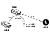
- V2X Vehicle to Everything
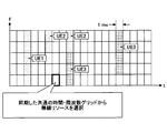
- V2X is a part of ITS (Intelligent Transport Systems), and as shown in FIG. 1, V2V (Vehicle to Vehicle), which means a communication mode between automobiles, is installed on the side of an automobile and a road.
- V2I Vehicle to Infrastructure
- RSU Road-Side Unit
- V2N Vehicle to
- Nomadic device and V2P (Vehicle to Pedestrian), which means a communication mode between a car and a pedestrian mobile terminal.
- the terminal on the transmitting side transmits HARQ-ACK corresponding to HARQ-ACK of the side link to the base station (gNB). More specifically, for example, the base station schedules the terminal, and the transmitting terminal transmits data to the receiving terminal by PSCCH / PSCH.
- the receiving terminal provides feedback on PSCCH / PSCH data transmission to the transmitting terminal, and based on this, the transmitting terminal provides HARQ-ACK feedback to the base station 10.
- a receiving unit that receives a signal from a base station and a periodic side link resource for transmitting data on the side link are set based on the signal received by the receiving unit.
- an uplink control channel resource for transmitting the first HARQ-ACK corresponding to the Hybrid Automatic Repeat Request (HARQ) -Acknowledgement (ACK) of the side link communication received by the receiving unit is set to the base station.
- a terminal is provided that includes a control unit that performs the first HARQ-ACK, and a transmission unit that transmits the first HARQ-ACK with the resources of the uplink control channel set by the control unit.
- the operation when the HARQ-ACK is transmitted from the terminal to the base station is clarified.
- V2X It is a figure for demonstrating V2X. It is a figure for demonstrating the side link. It is a figure for demonstrating the side link. It is a figure for demonstrating the MAC PDU used for side link communication. It is a figure for demonstrating the format of SL-SCH subhader. It is a figure for demonstrating the example of the channel structure used in the side link in LTE-V2X. It is a figure which shows the configuration example of the wireless communication system which concerns on embodiment. It is a figure for demonstrating the resource selection operation of a terminal. It is a figure which shows the outline of SL transmission mode 1 defined by V2X of NR. It is a figure which shows the outline of SL transmission mode 2a.
- the method of direct communication between terminals in the present embodiment is assumed to be LTE or NR side link (SL (Sidelink)), but the method of direct communication is not limited to this method.
- SL Sidelink
- the name "side link” is an example, and the name “side link” may not be used, and UL (Uplink) may include the function of SL.
- SL may be distinguished from DL (Downlink) or UL by the difference in frequency or time resource, or may have another name.
- UL and SL refer to a time resource, a frequency resource, a time / frequency resource, a reference signal for determining Pathloss in transmission power control, and a reference signal (PSS / SSS / PSSS / SSSS) used for synchronization. ) May be distinguished by the difference in any one or a plurality of combinations.
- the reference signal of antenna port X_ANT is used as a reference signal to be referred to in determining Pathloss in transmission power control, and in SL (including UL used as SL), Pathloss is determined in transmission power control.
- the reference signal to be referred to the reference signal of the antenna port Y_ANT is used.
- a terminal which may be called a user device (UE)
- UE user device
- the embodiment of the present invention is not limited to this mode.
- the terminal may be a terminal held by a person, the terminal may be a device mounted on a drone or an aircraft, and the terminal may be a base station, an RSU, a relay station (relay node), or a scheduling ability. It may be a user device or the like.
- side link is used as the basic technology
- the outline of the side link will be described as a basic example.
- An example of the technique described here is 3GPP Rel. This is the technology specified in 14 mag.
- the technique may be used in the NR, or a technique different from the technique may be used in the NR.
- side-link communication may be defined as direct communication performed between two or more adjacent user devices while using E-UTRA technology without going through a network node.
- Sidelinks may be defined as interfaces between user devices in sidelink communication.
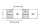
- a resource pool for the Discovery message is set (configured) for each Discovery period, and the terminal (referred to as the UE) is the Discovery message (discovery signal) in the resource pool. ) Is sent. More specifically, there are Type1 and Type2b.
- Type 1 the terminal autonomously selects a transmission resource from the resource pool.
- Type2b quasi-static resources are allocated by upper layer signaling (for example, RRC signal).
- a resource pool for SCI (Sidelink Control Information) / data transmission is periodically set for each SC (Sidelink Control) period.
- the terminal on the transmitting side notifies the receiving side of the data transmission resource (PSSCH resource pool) or the like by SCI with the resource selected from the Control resource pool (PSCCH resource pool), and transmits the data with the data transmission resource.
- PSSCH resource pool data transmission resource
- PSCCH resource pool Control resource pool
- Rel-14 in addition to mode 1 and mode 2, there are mode 3 and mode 4.
- SCI and data can be transmitted simultaneously (in one subframe) in resource blocks adjacent in the frequency direction.
- SCI may be referred to as SA (scheduling association).
- PSDCH Physical Sidelink Discovery Channel
- PSCCH Physical Sidelink Control Channel
- PSCCH Physical Sidelink Control Channel
- PSSCH Physical Sidelink Shared Channel
- PSCCH and PSSCH have a PUSCH-based structure, and have a structure in which DMRS (Demodulation Reference Signal, demodulation reference signal) is inserted.
- PSCCH may be referred to as a side link control channel
- PSCCH may be referred to as a side link shared channel.
- the signal transmitted via the PSCCH may be referred to as a sidelink control signal
- the signal transmitted via the PSCCH may be referred to as a sidelink data signal.
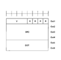
- the MAC (Medium Access Control) PDU (Protocol Data Unit) used for the side link is composed of at least a MAC header, a MAC Control element, a MAC SDU (Service Data Unit), and Padding.
- the MAC PDU may contain other information.
- the MAC header is composed of one SL-SCH (Siderink Sharped Channel) subheader and one or more MAC PDU subheaders.
- the SL-SCH subheader is composed of a MAC PDU format version (V), source information (SRC), destination information (DST), Reserved bit (R), and the like.
- V is assigned to the beginning of the SL-SCH subheader and indicates the MAC PDU format version used by the terminal.
- Information about the sender is set in the sender information.
- An identifier related to the ProSe UE ID may be set in the source information.
- Information about the destination is set in the destination information. In the destination information, information related to the ProSe Layer-2 Group ID of the destination may be set.
- FIG. 5 shows an example of the side link channel structure in LTE-V2X.
- the PSCCH resource pool and the PSCH resource pool used for "communication” are assigned.
- the PSDCH resource pool used for "discovery” is allocated in a cycle longer than the cycle of the "communication" channel. Note that PSDCH may not be included in NR-V2X.
- PSSS Primary Sidelink Synchronization signal
- SSSS Secondary Sidelink Synchronization signal
- PSBCH Physical Sidelink Broadcast Channel
- PSSS / SSSS and PSBCH are transmitted, for example, in one subframe.
- PSSS / SSSS may be referred to as SLSS.
- V2X assumed in this embodiment is a method related to "communication”. However, in the present embodiment, it may be assumed that there is no distinction between “communication” and “discovery”. In addition, the technique according to this embodiment may be applied in "discovery”.
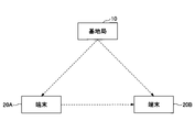
- FIG. 6 is a diagram showing a configuration example of a wireless communication system according to the present embodiment.
- the wireless communication system according to the present embodiment includes a base station 10, a terminal 20A, and a terminal 20B. Although there may actually be a large number of terminals, FIG. 6 shows terminals 20A and 20B as examples.
- the terminal 20A is intended to be the transmitting side and the terminal 20B is intended to be the receiving side, but both the terminal 20A and the terminal 20B have both a transmitting function and a receiving function.
- terminal 20 when the terminals 20A, 20B and the like are not particularly distinguished, they are simply described as "terminal 20" or "terminal".
- FIG. 6 shows a case where both the terminal 20A and the terminal 20B are within the coverage as an example, but the operation in the present embodiment is a case where all the terminals 20 are within the coverage and a case where some terminals 20 are within the coverage. It can be applied to both the case where it is in coverage and the other terminal 20 is out of coverage, and the case where all terminals 20 are out of coverage.
- the terminal 20 is, for example, a device mounted on a vehicle such as an automobile, and has a cellular communication function as a UE in LTE or NR and a side link function. Further, the terminal 20 includes a function of acquiring report information (position, event information, etc.) such as a GPS device, a camera, and various sensors. Further, the terminal 20 may be a general mobile terminal (smartphone or the like). Further, the terminal 20 may be an RSU. The RSU may be a UE type RSU having a UE function, a BS type RSU having a base station function (may be called a gNB type UE), or a relay station.
- the RSU may be a UE type RSU having a UE function, a BS type RSU having a base station function (may be called a gNB type UE), or a relay station.
- the terminal 20 does not have to be a device in one housing.
- the device including the various sensors is the terminal 20.
- the terminal 20 may be provided with a function of transmitting and receiving data to and from various sensors without including various sensors.
- the processing content of the side link transmission of the terminal 20 is basically the same as the processing content of the UL transmission in LTE or NR.
- the terminal 20 scrambles and modulates a codeword of transmission data to generate complex-valued symbols, maps the complex-valued symbols (transmission signal) to one or two layers, and performs precoding. Then, the precoded complex-valued symbols are mapped to the resource element to generate a transmission signal (eg, CP-OFDM, DFT-s-OFDM), which is transmitted from each antenna port.
- a transmission signal eg, CP-OFDM, DFT-s-OFDM
- the base station 10 a function of cellular communication as the base station 10 in LTE or NR and a function for enabling communication of the terminal 20 in the present embodiment (example: resource pool setting, resource allocation, etc.) )have.
- the base station 10 may be an RSU (gNB type RSU), a relay station, or a terminal having a scheduling function.
- RSU gNB type RSU
- the signal waveform used by the terminal 20 for SL or UL may be OFDMA, SC-FDMA, or other signal waveform. You may.
- a frame composed of a plurality of subframes (example: 10 subframes) is formed in the time direction, and a frame composed of a plurality of subcarriers is formed in the frequency direction.
- TTI Transmission Time Interval
- TTI is not always a subframe.
- TTI may be a slot or mini-slot or other time domain unit.
- the number of slots per subframe may be determined according to the subcarrier interval. Further, the number of symbols per slot may be 14 symbols.
- the terminal 20 is in mode 1, in which resources are dynamically allocated by (E) PDCCH ((Enhanced) Physical Downlink Control Channel) sent from the base station 10 to the terminal, and the terminal autonomously resources.
- Mode 2 which is a mode for selecting transmission resources from the pool, mode in which resources for SL signal transmission are allocated from the base station 10 (hereinafter referred to as mode 3), and resources for SL signal transmission are autonomously selected.
- mode 3 mode in which resources for SL signal transmission are allocated from the base station 10
- mode 4 Any mode of the mode (hereinafter referred to as mode 4) can be taken.
- the mode is set, for example, from the base station 10 to the terminal 20.
- the mode 4 terminal selects a radio resource from a synchronized common time / frequency grid.
- the terminal 20 performs sensing in the background, identifies a resource having a good sensing result and is not reserved for another terminal as a candidate resource, and selects a resource to be used for transmission from the candidate resources. To do.
- V2X of NR the same transmission mode as SL transmission mode 3 and SL transmission mode 4 defined in LTE V2X is defined.
- the transmission mode may be read as a resource allocation mode, and the name is not limited to this.
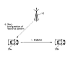
- FIG. 8A is a diagram showing an outline of SL transmission mode 1 defined by V2X of NR.
- the SL transmission mode 1 specified by V2X of NR corresponds to the SL transmission mode 3 specified by V2X of LTE.
- the base station 10 schedules transmission resources and allocates transmission resources to the transmission side terminal 20A.
- the terminal 20A transmits a signal to the receiving terminal 20B by the allocated transmission resource.
- FIGS. 8B, 8C, and 8D are diagrams showing an outline of SL transmission mode 2 defined by V2X of NR.
- the SL transmission mode 2 specified by V2X of NR corresponds to the SL transmission mode 4 specified by V2X of LTE.
- FIG. 8B is a diagram showing an outline of SL transmission mode 2a.
- the transmission side terminal 20A autonomously selects a transmission resource, and the selected transmission resource transmits a signal to the reception side terminal 20B.
- FIG. 8C is a diagram showing an outline of SL transmission mode 2c.
- the base station 10 sets a transmission resource with a fixed cycle in advance for the terminal 20A, and the terminal 20A receives a signal by the transmission resource with a fixed cycle set in advance. It is transmitted to the terminal 20B of.
- the base station 10 instead of the base station 10 presetting the transmission resource of the fixed cycle for the terminal 20A, for example, even if the transmission resource of the fixed cycle is set in advance for the terminal 20A according to the specifications. Good.
- FIG. 8D is a diagram showing an outline of SL transmission mode 2d.
- the terminal 20 performs the same operation as the base station 10. Specifically, the terminal 20 schedules the transmission resource and allocates the transmission resource to the transmission side terminal 20A. The terminal 20A may transmit to the receiving terminal 20B by the allocated communication resource. That is, the terminal 20 may control the transmission of another terminal 20.
- NR As shown in FIGS. 9A to 9C, three types of communication, unicast, group cast, and broadcast, are currently under consideration.
- FIG. 9A is a diagram showing an example of unicast Physical Sidelink Sharp Channel (PSCCH) / Physical Sidelink Control Channel (PSSCH) transmission.
- Unicast means, for example, one-to-one transmission from the transmitting side terminal 20A to the receiving side terminal 20B.
- FIG. 9B is a diagram showing an example of group cast PSCCH / PSCH transmission.
- the group cast means, for example, transmission from the transmitting side terminal 20A to the terminal 20B and the terminal 20B'which are a group of the receiving side terminal 20.
- FIG. 9C is a diagram showing an example of broadcast PSCCH / PSCH transmission.
- Broadcast refers to, for example, transmission from terminal 20A on the transmitting side to all terminals 20 on the receiving side within a predetermined range, terminal 20B, terminal 20B', and terminal 20B''.
- New Radio (NR) -Sidelink (SL) of Release 16 of the Third Generation Partnership Project (3GPP) is expected to support Hybrid Automatic Repeat Request (HARQ) feedback.
- NR New Radio
- SL idelink
- HARQ Hybrid Automatic Repeat Request
- CG composite grant
- the base station 10 sets periodic sidelink radio resources (time and frequency resources) for the terminal 20, and the terminal 20 uses the set periodic sidelink radio resources.
- Data can be transmitted to the terminal 20 on the receiving side.
- NR-Uu an interface between a 5G user device and a 5G Radio Access Network (RAN)
- RAN 5G Radio Access Network
- periodic radio resources are set for the terminal 20 (quasi-statically) by the parameters of the upper layer, and the terminal 20 is set without receiving the DCI for allocating the radio resources.
- Data can be transmitted using periodic radio resources.
- the radio resource may be available until the setting is changed by RRC-recomposition.
- a periodic radio resource is set for the terminal 20 by a parameter of the upper layer, and the terminal 20 activates or deactivates the periodic radio resource based on the received Downlink Control Information (DCI). (Release) can be performed.
- DCI Downlink Control Information
- Type 1 CG and Type 2 CG are also applied to NR side-link communication.
- HARQ-ACK Hybrid Automatic Repeat Request
- PSFCH Physical Sidelink Feedback Channel
- PSCCH Physical Sidelink Control Channel
- PSSCH Physical Sidelink Shared Channel
- Send HARQ-ACK As shown in FIG. 10, PSFCH may be mapped to one or more symbols at the end with respect to slot time. Since PSFCH resources are associated with PSCCH and / or PSSCH in the time domain, it may not be expected that PSFCH resources will be dynamically specified in the time domain. Moreover, the resource determination method of PSFCH is not limited to this.
- the transmitting terminal 20 transmits the side link HARQ-ACK to the base station 10 (gNB) as shown in FIG. .. More specifically, for example, as shown in FIG. 11, the base station 10 schedules the terminal # A, and the terminal # A transmits data to the terminal # B by PSCCH / PSSCH. Terminal # B provides feedback on PSCCH / PSCH data transmission to terminal # A, and based on this, terminal # A provides feedback on HARQ-ACK to base station 10.
- the present invention is not limited to this, and is also applicable to the case where the terminal # B gives the HARQ-ACK feedback to the base station 10.
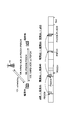
- FIG. 12 is a diagram showing an example in the case where the configured grant is applied and HARQ is applied in SL transmission mode 1.
- the base station 10 sets a configured grant (CG) for the terminal #A.
- the terminal #A transmits data (for example, a transport block) to the terminal #B with the PSCCH / PSSCH resource corresponding to the set CG.
- terminal # B transmits HARQ-ACK for the data transmission in step 102 to terminal # A by PSFCH.
- terminal #A transmits HARQ-ACK to base station 10. Steps 102 to 104 are repeated based on the periodic resources set in step 101. Further, activation of CG by DCI may be added between step 101 and step 102. Here, it is necessary to determine the resources in the time domain and the frequency domain when transmitting the HARQ-ACK in step 104.
- Proposal A proposes a method of designating a resource of the Physical Uplink Control Channel (PUCCH) when the terminal #A transmits HARQ-ACK to the base station 10 in step 104 of FIG. That is, in the proposal A, a method of designating the PUCCH resource in the slot in which the terminal #A transmits HARQ-ACK is proposed.
- the slot for transmitting HARQ-ACK by the terminal #A may be specified by a method described later or another method.
- terminal #A may transmit HARQ-ACK to the base station 10 with the PUCCH resource (or the corresponding PUSCH resource) set by the parameter of the upper layer.
- the base station 10 transmits DCI to the terminal 20 to periodically activate or deactivate the radio resource.
- the transmission of HARQ-ACK from the terminal 20 for the data (for example, transport block) communication in the CG resource immediately after the transmission of the DCI from the base station 10 may be excluded from the target of the proposal A, and the proposal It may be included in A. That is, when excluded, it may be assumed that the terminal 20 transmits HARQ-ACK with the PUCCH resource specified by the DCI.
- a method similar to the downlink semi-persistent scheduling (DL SPS) in the NR of Release 15 may be applied.
- DL SPS downlink semi-persistent scheduling
- PUCCH-ReachyId for transmitting HARQ-ACK corresponding to data transmission in the transmission resource set by SPS-Config is set by n1PUCCH-AN included in SPS-Config. It is specified.
- the base station 10 may set a Configured GrantConfig-sidelink including at least one n1PUCCH-AN as a parameter of the upper layer.
- Configured Grant Config-sidelink may be a parameter for setting the configured grant of the side link for the terminal 20.
- the name ConfiguredGrantConfig-sidelink is an example, and the name of the parameter for setting the sidelink configured grant for the terminal 20 is not limited to this example.
- the base station 10 may include n1PUCCH-AN and one of the following parameters in the Configured GrantConfig-sidelink.
- the parameter name included in the ConfiguredGrantConfig-sidelink is an example, and the name is not limited to this.
- Uci-OnPUSCH Indicates the value of beta-offset in the case of Uci-OnPUSCH ⁇ Configured GrantTimer
- the n1PUCCH-AN included in the ConfiguredGrantConfig-sidelink may specify the PUCCH-ResourceId for transmitting the HARQ-ACK corresponding to the transmission of data in the resource set by the ConfigureGrantConfig-sidelink, and is linked to some PUCCH resource. It may be attached.
- PUCCH-ValueId of PUCCH form0 or PUCCHformat1 may be specified. In this case, for example, the following conditions may be added. -When the transmission of PSCH (transport block) based on the code block group (CBG) is not set / instructed, and / or the transmission of PSCH based on CBG is set, but the PSCH transmitted on the CG resource of the side link. When the HARQ-ACK bit corresponding to is up to 2 bits and / or when each HARQ-ACK corresponding to the PSCH of the side link CG resource is transmitted separately to the base station 10, n1PUCCH-AN May specify PUCCH-ResourceId of PUCCH form0 or PUCCH form1. -In cases other than the above, n1PUCCH-AN may specify PUCCH-ResourceId of PUCCH format2, PUCCHformat3, or PUCCHformat4.
- n1PUCCH-AN-1 and n1PUCCH-AN-2 may be specified as n1PUCCH-AN.
- n1PUCCH-AN-1 may specify PUCCH-ReachyId of PUCCH format0 or PUCCH format1 (that is, PUCCH format capable of transmitting up to 2 bits). Good.
- n1PUCCH-AN-2 is PUCCH of PUCCH form2, PUCCHformat3, or PUCCHformat4 (that is, PUCCH format capable of transmitting 3 bits or more).
- -ResourceId may be specified.
- the transmission of PSCH based on the code block group (CBG) is not set / instructed, and / or the transmission of PSCH based on CBG is set, but HARQ-ACK corresponding to the PSCH of the CG resource of the side link.
- CBG code block group
- the n1PUCCH-AN-1 is configured as a Defined GrantConfig-. It may be used to transmit HARQ-ACK corresponding to data transmission with the resource set by sidelink. In cases other than the above, n1PUCCH-AN-2 may be used to transmit the HARQ-ACK corresponding to the data transmission with the resource set by the Configured GrantConfig-sidelink.
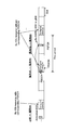
- FIG. 13 is a diagram showing an example of Proposal A.
- the base station 10 sets the configured grant (CG) by transmitting the parameter Configured GrantConfig-sidelink of the upper layer including n1PUCCH-AN to the terminal #A.
- the terminal #A transmits data to the terminal #B with the PSCCH / PSSCH resource corresponding to the set CG.
- the terminal #B transmits HARQ-ACK for the data transmission in step 202 to the terminal #A by PSFCH.
- terminal # A transmits HARQ-ACK to base station 10.
- the terminal #A transmits HARQ-ACK to the base station 10 by using the PUCCH resource specified by n1PUCCH-AN included in the ConfiguredGrantConfig-sidelink transmitted in step 201.
- the HARQ-ACK bit corresponding to the data (for example, transport block) communication in the CG resource immediately after the transmission of the DCI for the periodic activation of the radio resource of the side link is the HARQ corresponding to the DL transmission. It may be multiplexed with the -ACK bit and / or the HARQ-ACK bit corresponding to side link communication in resources other than CG. Since the PUCCH resource for multiple transmission is the resource specified by the last DCI, HARQ corresponding to data (for example, transport block) communication in the CG resource immediately after the transmission of the DCI for the activation is performed. It is desirable that the transmission of the -ACK bit be dynamically instructed based on the DCI.
- the transmission of the HARQ-ACK bit corresponding to the data (for example, transport block) communication in the CG resource other than the CG resource immediately after the transmission of the DCI for the activation is the transmission of the HARQ-ACK corresponding to the DL transmission.
- the last DCI is a DCI other than the activation DCI, so no dynamic instruction is required. .. Therefore, it is possible to apply the method of Proposal A so that the PUCCH resource to be used can be specified by a different method depending on whether or not it is immediately after the periodic activation of the radio resource of the side link.
- Provision B A resource for transmitting HARQ-ACK from the terminal 20 to the base station 10 as a PUCCH resource (or a PUSCH resource corresponding to the PUCCH) specified by DCI for activating the periodic radio resource of the side link. You may use it continuously.
- Proposal B is applied to Type 2 CG and Proposal A is applied to Type 1 CG. It may be applied to CG.
- the DCI for periodic activation of radio resources on the sidelinks may specify one PUCCH resource from the PUCCH resource set.
- the PUCCH resource specified by the DCI may be used as a resource for transmitting HARQ-ACK from the terminal 20 to the base station 10.
- the PUCCH resource set is the same as the PUCCH resource set used to transmit the HARQ-ACK for the data (eg, transport block) transmitted by the sidelink's dynamically scheduled resource. It may be the same as or different from the PUCCH resource set used to transmit the HARQ-ACK for DL transmission.
- FIG. 14 is a diagram showing an example of Proposal B.
- the base station 10 transmits a parameter of the upper layer Configured GrantConfig-sidelink to the terminal #A to set the configured grant (CG), and for CG activation.
- a DCI which is a DCI and includes a PUCCH resource indicator, is transmitted to the terminal #A.
- the terminal #A transmits data to the terminal #B using the PSCCH / PSSCH resources corresponding to the set CG.
- terminal # B transmits HARQ-ACK for the data transmission in step 302 to terminal # A by PSFCH.
- terminal # A transmits HARQ-ACK to base station 10.
- the terminal #A transmits HARQ-ACK to the base station 10 by using the PUCCH resource specified by the PUCCH resource indicator included in the DCI transmitted in step 301.
- PUCCH resources can be specified more flexibly. Further, according to the method of Proposal B, since the PUCCH resource can be specified more flexibly, for example, HARQ-ACK for transmission by CG of the side link is set to other HARQ-ACK (for example, NR-). This is effective when transmitting to the base station 10 without multiplexing with Uu's HARQ-ACK).
- HARQ-ACK for transmission by CG of the side link is set to other HARQ-ACK (for example, NR-). This is effective when transmitting to the base station 10 without multiplexing with Uu's HARQ-ACK).
- the terminal 20 does not have to transmit the HARQ-ACK corresponding to the data transmission, which is the data transmission by the side link CG resource and does not accompany the corresponding PDCCH, to the base station 10.
- the terminal 20 uses the PDCCH to perform HARQ-ACK corresponding to data transmission with the CG resource of the side link corresponding to the PDCCH (for example, DCI for the periodic activation of the radio resource of the side link). It may be transmitted by the designated PUCCH resource (or the PUSCH resource corresponding to the PUCCH resource).
- FIG. 15 is a diagram showing an example of Proposal C.
- FIG. 15 shows that the terminal 20A does not transmit the HARQ-ACK corresponding to the data transmission, which is the data transmission by the side link CG resource and does not accompany the corresponding PDCCH, to the base station 10.
- the terminal 20 transmits the data (for example, the transport block) by the CG resource of the side link, and performs the HARQ-ACK corresponding to the data transmission without the corresponding PDCCH as the base station.
- the terminal 20 transmits the data (for example, the transport block) by the CG resource of the side link, and performs the HARQ-ACK corresponding to the data transmission without the corresponding PDCCH as the base station.
- the terminal 20 transmits the data (for example, the transport block) by the CG resource of the side link, and performs the HARQ-ACK corresponding to the data transmission without the corresponding PDCCH as the base station.
- Proposal D The terminal 20 transmits the HARQ-ACK corresponding to the data transmission, which is the data transmission by the CG resource of the side link and is not accompanied by the corresponding PDCCH, by the PUCCH resource included in the slot designated by the base station 10.
- Proposal D is a method of designating a slot for transmitting the HARQ-ACK, and the method of designating the PUCCH resource in the slot may be Proposal A and / or Proposal B, or another method. Good.
- the slot to be transmitted by the same method may be specified.
- the base station 10 and the terminal 20 it is possible for the base station 10 and the terminal 20 to have a common recognition about the timing (for example, slot) of transmitting HARQ-ACK, and the data in the CG resource (for example, a transformer) can be shared. It becomes possible to appropriately transmit HARQ-ACK for transmission (port block) to the base station 10.
- the terminal 20 is a PUCCH resource included in a slot designated by DCI for the periodic activation of the radio resource of the side link, which is data transmission by the CG resource of the side link and is not accompanied by a corresponding PDCCH.
- Data transmission, HARQ-ACK may be transmitted to the base station 10.
- FIG. 16 is a diagram showing an example of Proposal D.
- the terminal 20 performs PSCCH / PSCH transmission with the CG resource of the side link, and PSCCH / PSCH transmission without the corresponding PDCCH, in slot n.
- the terminal 20 may transmit the HARQ-ACK corresponding to the PSCCH / PSCH transmission to the base station 10 by the PUCCH (or the corresponding PUSCH) included in the slot n + k.
- k may be specified in the PSCCH-to-HARQ-timing indicator field or PSCH-to-HARQ-timing indicator field included in the DCI format for the periodic activation of radio resources on the sidelinks. ..
- FIG. 17 is a diagram showing another example of Proposal D.
- the terminal 20 is a PSCCH / PSCH transmission with the CG resource of the side link, and the PSCCH / PSCH transmission without the corresponding PDCCH is received by the PSFCH (side from the terminal 20B). It is assumed that HARQ-ACK reception of the link) is performed in slot n.
- the terminal 20 may transmit the HARQ-ACK corresponding to the PSCCH / PSCH transmission to the base station 10 by the PUCCH (or the corresponding PUSCH) included in the slot n + k.
- k may be specified in the PSFCH-to-HARQ-timing indicator field included in the DCI format for periodic activation of radio resources on the sidelinks.
- FIG. 18 is a diagram showing another example of Proposal D.
- the terminal 20 receives a DCI in slot n for periodic activation of radio resources on the sidelinks.
- the terminal 20 may transmit the HARQ-ACK corresponding to the PSCCH / PSCH transmission in the slot n + k + P ⁇ N.
- k may be specified in the PDCCH-to-HARQ-timing indicator field included in the DCI format for the periodic activation of radio resources on the sidelinks.
- P may be the CG cycle of the side link.
- N may be the number of transmission opportunities in the sidelink CG resource after activation. Note that N may specify the number of transmission opportunities in the time direction.
- N may specify the number of transmission opportunities in the time and frequency directions (which may be subchannels) (in this case, the formula indicating the slot above may be modified as appropriate).
- the slot may be a slot in which an offset value is added to the above n + k + P ⁇ N.
- the terminal 20 is a PUCCH resource included in the slot specified by the parameter of the upper layer, and performs HARQ-ACK corresponding to data transmission, which is data transmission by the CG resource of the side link and is not accompanied by the corresponding PDCCH. , May be transmitted to the base station 10.
- the terminal 20 may transmit the HARQ-ACK corresponding to the PSCCH / PSCH transmission to the base station 10 with the PUCCH resource (or the corresponding PUSCH resource) included in the slot n + k.
- k may be specified by a parameter of the upper layer.
- the terminal 20 is a PSCCH / PSCH transmission with the CG resource of the side link, and is received by the PSFCH for the PSCCH / PSCH transmission without the corresponding PDCCH (reception of the HARQ-ACK of the side link from the terminal 20B). Is assumed to be performed in slot n. In this case, the terminal 20 may transmit the HARQ-ACK corresponding to the PSCCH / PSCH transmission to the base station 10 with the PUCCH resource (or the corresponding PUSCH resource) included in the slot n + k.
- k may be specified by a parameter of the upper layer.
- the base station 10 recognizes that the terminal 20 does not transmit the side link channel with the side link CG resource. Can't. In this case, if the terminal 20 does not transmit the HARQ-ACK, the base station 10 may erroneously determine that the reception of the HARQ-ACK has failed. In such a case, the base station 10 may determine that the reception of the negative acquired generation (NACK) has failed, and dynamically allocate the additional side link resource to the terminal 20. However, the terminal 20 merely does not transmit the side link channel with the CG resource of the side link, and allocation of such an additional side link resource is unnecessary. In order to prevent such unnecessary allocation of sidelink resources, the method of Proposal E can be applied.
- the terminal 20 When the terminal 20 does not transmit the side link channel with the side link CG resource, the terminal 20 is an acknowledgment (Acknowledgement (ACK)) as HARQ-ACK with the set PUCCH resource or the specified PUCCH resource. May be sent.
- ACK Acknowledgement
- FIG. 19 is a diagram showing an example of Proposal E1.
- the base station 10 transmits the parameter Configured GrantConfig-sidelink of the upper layer to the terminal #A to set the configured grant (CG), and is a DCI for CG activation, which is a PUCCH resource indicator.
- DCI including, is transmitted to terminal # A.
- the terminal #A does not transmit the side link data to the terminal 20B because, for example, there is no data to be transmitted. Therefore, in step 402, terminal #A transmits an acknowledgment (ACK) to the base station 10 as HARQ-ACK with the PUCCH resource specified by DCI.
- ACK acknowledgment
- different carriers may be applied to Uu and the side link.
- different numerologies may be applied to Uu and sidelinks in the above embodiments.
- the parameters n, k, P, N in the above-described embodiment are set with reference to Uu.
- the side link it is conceivable to set the side link as a reference.
- the parameters n, k, P, N in the above-described embodiment may be set based on the carrier of PUCCH. For example, when the subcarrier interval (SCS) of the PSCCH / PSCH carrier is larger than the subcarrier interval of the PUCCH carrier, the HARQ-ACK of the PSCCH / PSCH with a large subcarrier interval is larger than the subcarrier interval of the PSCCH / PSCH.
- SCS subcarrier interval
- the HARQ-ACK of the PSCCH / PSCH having a small subcarrier interval is the subcarrier of the PSCCH / PSCH.
- the parameters n, k, P, N in the above-described embodiment may be set based on the carrier of PSCCH / PSCH.
- the parameters n, k, P, N in the above-described embodiment may be set based on the carrier of PSFCH.
- the parameters n, k, P, N in the above-described embodiment may be set based on the carrier of PDCCH.
- FIG. 20 is a diagram showing an example of the functional configuration of the base station 10.
- the base station 10 has a transmitting unit 101, a receiving unit 102, and a control unit 103.
- the functional configuration shown in FIG. 20 is only an example. Any function classification and name of the functional unit may be used as long as the operation according to the present embodiment can be executed.
- the transmitter 101 may be referred to as a transmitter, and the receiver 102 may be referred to as a receiver.
- the transmission unit 101 includes a function of generating a signal to be transmitted to the terminal 20 side and transmitting the signal wirelessly.
- the receiving unit 102 includes a function of receiving various signals transmitted from the terminal 20 and acquiring, for example, information of a higher layer from the received signals.
- the receiving unit 102 includes a function of measuring the received signal and acquiring a quality value.
- the control unit 103 controls the base station 10.
- the function of the control unit 103 related to transmission may be included in the transmission unit 101, and the function of the control unit 103 related to reception may be included in the reception unit 102.
- control unit 103 of the base station 10 sets a periodic resource (configured grant (CG)) for the side link communication in the terminal 20, and sets a periodic resource for the side link communication. Is created, and the transmission unit 101 transmits the message to the terminal 20.
- CG configured grant
- the control unit 103 of the base station 10 transmits HARQ-ACK to the base station 10 in the slot.
- the parameters of the upper layer for designating the PUSCH resource for the purpose may be created, and the transmission unit 101 may transmit the parameters of the upper layer to the terminal 20.
- control unit 103 of the base station 10 provides the DCI for the periodic activation of the radio resource of the side link with information for designating the PUCCH resource for the terminal 20 to transmit the HARQ-ACK to the base station 10.
- the transmission unit 101 may transmit the DCI to the terminal 20.
- control unit 103 of the base station 10 creates a parameter of the upper layer for specifying the PUCCH resource for transmitting the HARQ-ACK to the base station 10 in the slot for the CG of Type 1, and transmits it.
- the unit 101 is made to transmit the parameters of the upper layer to the terminal 20, and the control unit 103 of the base station 10 is used for the CG of the type 2 to the DCI for the periodic activation of the radio resource of the side link.
- the transmission unit 101 may be made to transmit the DCI to the terminal 20, including the information specifying the PUCCH resource for the terminal 20 to transmit the HARQ-ACK to the base station 10.
- control unit 103 of the base station 10 causes the terminal 20 to transmit the HARQ-ACK corresponding to the data transmission using the side-link CG resource without the corresponding PDCCH to the base station 10.
- a slot for the purpose and a PUCCH resource included in the slot may be set.
- FIG. 21 is a diagram showing an example of the functional configuration of the terminal 20.
- the terminal 20 has a transmission unit 201, a reception unit 202, and a control unit 203.
- the functional configuration shown in FIG. 21 is only an example. Any function classification and name of the functional unit may be used as long as the operation according to the present embodiment can be executed.
- the transmitter 201 may be referred to as a transmitter, and the receiver 202 may be referred to as a receiver.
- the terminal 20 may be the transmitting side terminal 20A or the receiving side terminal 20B. Further, the terminal 20 may be a scheduling terminal 20.
- the transmission unit 201 creates a transmission signal from the transmission data and wirelessly transmits the transmission signal.
- the receiving unit 202 wirelessly receives various signals and acquires a signal of a higher layer from the received signal of the physical layer. Further, the receiving unit 202 includes a function of measuring the received signal and acquiring a quality value.
- the control unit 203 controls the terminal 20.
- the function of the control unit 203 related to transmission may be included in the transmission unit 201, and the function of the control unit 203 related to reception may be included in the reception unit 202.
- the receiving unit 202 of the terminal 20 includes an upper layer parameter including the setting information of the configured grant (CG) which is the setting information of the resource for the periodic data transmission of the side link transmitted from the base station 10.
- CG configured grant
- the control unit 203 of the base station 10 sets the CG according to the CG setting information included in the parameters of the received upper layer, and the transmission unit 201 of the base station 10 uses the set CG resources. Then, the side link data is transmitted.
- the receiving unit 202 of the terminal 20 transmits HARQ-ACK to the base station 10 when the terminal 20 specifies a slot for transmitting the HARQ-ACK to the base station 10. It may receive higher layer parameters that include information that specifies the resources of the PUCCH of.
- the control unit 203 of the terminal 20 creates a HARQ-ACK corresponding to the HARQ-ACK of the side link to be transmitted to the base station 10.
- the transmission unit 201 of the terminal 20 transmits the HARQ-ACK corresponding to the HARQ-ACK of the side link to the base station 10 using the PUCCH resource specified by the information included in the parameters of the upper layer. You may.
- the receiving unit 202 of the terminal 20 receives the DCI for activating the resource for the periodic data transmission of the side link, and the control unit 203 of the terminal 20 receives the PUCCH resource specified by the DCI. , It may be set as a resource for transmitting HARQ-ACK from the terminal 20 to the base station 10.
- control unit 203 of the terminal 20 is for the terminal 20 designated by the parameters of the upper layer received from the base station 10 by the receiving unit 202 to transmit HARQ-ACK to the base station 10 with respect to the CG of Type 1.
- a PUCCH resource may be set, and the transmission unit 201 of the terminal 20 may transmit HARQ-ACK to the base station 10 using the set PUCCH resource.
- the control unit 203 of the terminal sets the terminal 20 to the CG of Type 2 according to the information contained in the DCI for activating the periodic radio resource of the side link received from the base station 10 by the receiving unit 202.
- a PUCCH resource for transmitting HARQ-ACK to the base station 10 may be set, and the transmission unit 201 of the terminal 20 may transmit the HARQ-ACK to the base station 10 using the set PUCCH resource.
- control unit 203 of the terminal 20 does not transmit the HARQ-ACK corresponding to the data transmission, which is the data transmission by the CG resource of the side link and does not accompany the corresponding PDCCH, to the base station 10. May be determined.
- the control unit 203 of the terminal 20 uses the CG resource of the side link to transmit data, and uses the base as a resource for transmitting HARQ-ACK corresponding to the data transmission without the corresponding PDCCH to the base station 10.
- the PUCCH resource included in the slot designated by the station 10 may be set.
- the control unit 203 of the terminal 20 when the base station 10 sets the side link CG for the terminal 20 and / or when the side link CG resource is activated, the control unit 203 of the terminal 20 side with the side link CG resource. Regardless of whether or not the link channel is transmitted, the PUCCH resource (or the corresponding PUSCH resource) is set, and the transmission unit 201 of the terminal 20 transmits HARQ-ACK to the base station 10.
- each functional block may be realized by using one physically or logically connected device, or directly or indirectly (for example, two or more physically or logically separated devices). , Wired, wireless, etc.) and may be realized using these plurality of devices.
- the functional block may be realized by combining the software with the one device or the plurality of devices.
- Functions include judgment, decision, judgment, calculation, calculation, processing, derivation, investigation, search, confirmation, reception, transmission, output, access, solution, selection, selection, establishment, comparison, assumption, expectation, and assumption.
- broadcasting notifying, communicating, forwarding, configuring, reconfiguring, allocating, mapping, assigning, etc., but only these. I can't.
- a functional block (constituent unit) for functioning transmission is called a transmitting unit or a transmitter.
- the method of realizing each of them is not particularly limited.
- FIG. 22 is a diagram showing an example of the hardware configuration of the terminal 20 and the base station 10 according to the present embodiment.
- the terminal 20 and the base station 10 may be physically configured as a computer device including a processor 1001, a memory 1002, a storage 1003, a terminal 1004, an input device 1005, an output device 1006, a bus 1007, and the like.
- the word “device” can be read as a circuit, device, unit, etc.
- the hardware configuration of the terminal 20 and the base station 10 may be configured to include one or more of the devices shown in 1001 to 1006 shown in the figure, or may be configured not to include some of the devices. May be good.
- the processor 1001 For each function of the terminal 20 and the base station 10, the processor 1001 performs an operation by loading predetermined software (program) on the hardware such as the processor 1001 and the memory 1002, and controls the communication by the terminal 1004. It is realized by controlling at least one of reading and writing of data in the memory 1002 and the storage 1003.
- predetermined software program
- the processor 1001 operates, for example, an operating system to control the entire computer.
- the processor 1001 may be configured by a central processing unit (CPU: Central Processing Unit) including an interface with a peripheral device, a control device, an arithmetic unit, a register, and the like.
- CPU Central Processing Unit
- the processor 1001 reads a program (program code), a software module, data, etc. from at least one of the storage 1003 and the communication terminal 1004 into the memory 1002, and executes various processes according to these.
- a program program code
- a program that causes a computer to execute at least a part of the operations described in the above-described embodiment is used.
- the control unit 203 of the terminal 20 may be realized by a control program stored in the memory 1002 and operating in the processor 1001, and may be realized in the same manner for other functional blocks.
- Processor 1001 may be implemented by one or more chips.
- the program may be transmitted from the network via a telecommunication line.
- the memory 1002 is a computer-readable recording medium, and is composed of at least one such as a ROM (Read Only Memory), an EPROM (Erasable Programmable ROM), an EEPROM (Electrically Erasable Programmable ROM), and a RAM (Random Access Memory). May be done.
- the memory 1002 may be referred to as a register, a cache, a main memory (main storage device), or the like.
- the memory 1002 can store a program (program code), a software module, or the like that can be executed to implement the wireless communication method according to the embodiment of the present disclosure.
- the storage 1003 is a computer-readable recording medium, for example, an optical disk such as a CD-ROM (Compact Disc ROM), a hard disk drive, a flexible disk, a magneto-optical disk (for example, a compact disk, a digital versatile disk, a Blu-ray). It may consist of at least one (registered trademark) disk), smart card, flash memory (eg, card, stick, key drive), floppy (registered trademark) disk, magnetic strip, and the like.
- the storage 1003 may be referred to as an auxiliary storage device.
- the storage medium described above may be, for example, a database, server or other suitable medium containing at least one of memory 1002 and storage 1003.
- the communication terminal 1004 is hardware (transmission / reception device) for communicating between computers via at least one of a wired network and a wireless network, and is also referred to as, for example, a network device, a network controller, a network card, a communication module, or the like.
- the communication terminal 1004 includes, for example, a high frequency switch, a duplexer, a filter, a frequency synthesizer, etc. in order to realize at least one of frequency division duplex (FDD: Frequency Division Duplex) and time division duplex (TDD: Time Division Duplex). It may be composed of.
- FDD Frequency Division Duplex
- TDD Time Division Duplex
- the input device 1005 is an input device (for example, a keyboard, a mouse, a microphone, a switch, a button, a sensor, etc.) that receives an input from the outside.
- the output device 1006 is an output device (for example, a display, a speaker, an LED lamp, etc.) that outputs to the outside.
- the input device 1005 and the output device 1006 may have an integrated configuration (for example, a touch panel).
- each device such as the processor 1001 and the memory 1002 is connected by the bus 1007 for communicating information.
- the bus 1007 may be configured by using a single bus, or may be configured by using a different bus for each device.
- the terminal 20 and the base station 10 are hardware such as a microprocessor, a digital signal processor (DSP: Digital Signal Processor), ASIC (Application Specific Integrated Circuit), PLD (Programmable Logic Device), and FPGA (Field Programmable Gate Array), respectively. It may be configured to include hardware, and a part or all of each functional block may be realized by the hardware. For example, processor 1001 may be implemented using at least one of these hardware.
- DSP Digital Signal Processor
- ASIC Application Specific Integrated Circuit
- PLD Programmable Logic Device
- FPGA Field Programmable Gate Array
- a periodic side link resource for transmitting data on the side link is set, and the receiving unit receives the signal.
- a control unit that sets resources for an uplink control channel for transmitting a first HARQ-ACK corresponding to a Hybrid Automatic Repeat Request (HARQ) -Acknowledgement (ACK) of side link communication to the base station, and the first A terminal including a transmission unit that transmits HARQ-ACK with the resources of the uplink control channel set by the control unit.
- HARQ Hybrid Automatic Repeat Request
- ACK Acknowledgement
- HARQ-ACK is transmitted from the terminal 20 to the base station 10.
- the PUCCH resource will be explicitly specified, and the operation when HARQ-ACK is transmitted from the terminal 20 to the base station 10 will be clarified.
- the control unit may set the resource of the uplink control channel based on the identifier included in the parameter of the upper layer included in the signal received by the reception unit. Further, the control unit may set the timing of the slot including the resource of the uplink control channel based on the downlink control information received by the reception unit.
- the periodic sidelink resource is a first-class periodic sidelink resource that can be continuously used without the receiver receiving downlink control information for allocating radio resources.
- it is a second type of periodic sidelink resource that can be continuously used after activation by the control information received by the receiving unit, and the periodic sidelink resource is the first type of resource.
- the control unit sets the resource of the uplink control channel based on the identifier included in the parameter of the upper layer included in the signal received by the receiving unit, and sets the resource of the uplink control channel.
- the control unit may set the resource of the uplink control channel based on the control information.
- DCI for periodic radio resource activation of sidelinks is used only for Type 2 CG.
- Type 2 CG when transmitting HARQ-ACK from the terminal to the base station for the PUCCH resource specified by DCI for the periodic activation of the radio resource of the side link. It is possible to set it as a PUCCH resource, and in the case of Type 1 CG, set the PUCCH resource when transmitting HARQ-ACK from the terminal to the base station according to the parameters of the upper layer from the base station.
- the transmission unit is a side link resource of any one of the periodic side link resources, and when the side link data is not transmitted, the uplink control channel set by the control unit is used.
- the resource may transmit a second HARQ-ACK to the base station.
- the base station may not be able to recognize that the terminal does not transmit the side link channel with the side link CG resource. is there. In this case, if the terminal does not transmit the HARQ-ACK to the base station, the base station may erroneously determine that the reception of the HARQ-ACK has failed. In such a case, the base station may determine that the reception of the negative acquired ground (NACK) has failed and dynamically allocate the additional side link resource to the terminal.
- NACK negative acquired ground
- the terminal merely does not transmit the side link channel with the CG resource of the side link, and allocation of such an additional side link resource is unnecessary. According to the above configuration, it is possible to prevent such unnecessary allocation of sidelink resources.
- the resource of the periodic side link for transmitting data on the side link is set, and the hybrid automatic repeat request of the side link communication to be received is set.
- a method of communication by a terminal comprising a step of transmitting with a control channel resource.
- HARQ-ACK is transmitted from the terminal 20 to the base station 10.
- the PUCCH resource will be explicitly specified, and the operation when HARQ-ACK is transmitted from the terminal 20 to the base station 10 will be clarified.
- the operation of the plurality of functional units may be physically performed by one component, or the operation of one functional unit may be physically performed by a plurality of components.
- the order of processing may be changed as long as there is no contradiction.
- the terminal 20 and the base station 10 have been described with reference to functional block diagrams, but such devices may be implemented in hardware, software, or a combination thereof.
- the software operated by the processor of the terminal 20 according to the embodiment of the present invention and the software operated by the processor of the base station 10 according to the embodiment of the present invention are random access memory (RAM), flash memory, and read-only memory, respectively. It may be stored in (ROM), EPROM, EEPROM, registers, hard disk (HDD), removable disk, CD-ROM, database, server or any other suitable storage medium.
- information notification includes physical layer signaling (for example, DCI (Downlink Control Information), UCI (Uplink Control Information)), higher layer signaling (for example, RRC (Radio Resource Control) signaling, MAC (Medium Access Control) signaling, etc. It may be carried out by notification information (MIB (Master Information Block), SIB (System Information Block)), other signals, or a combination thereof.
- RRC signaling may be called an RRC message, and may be, for example, an RRC connection setup (RRC Connection Setup) message, an RRC connection reconfiguration (RRC Connection Reconfiguration) message, or the like.
- Each aspect / embodiment described in the present disclosure includes LTE (Long Term Evolution), LTE-A (LTE-Advanced), SUPER 3G, IMT-Advanced, 4G (4th generation mobile communication system), and 5G (5th generation mobile communication).
- system FRA (Future Radio Access), NR (new Radio), W-CDMA (registered trademark), GSM (registered trademark), CDMA2000, UMB (Ultra Mobile Broadband), LTE 802.11 (Wi-Fi (registered trademark)) )), LTE 802.16 (WiMAX®), IEEE 802.20, UWB (Ultra-WideBand), Bluetooth®, and other systems that utilize suitable systems and have been extended based on these. It may be applied to at least one of the next generation systems. Further, a plurality of systems may be applied in combination (for example, a combination of at least one of LTE and LTE-A and 5G).
- the specific operation performed by the base station 10 in the present disclosure may be performed by its upper node.
- various operations performed for communication with a terminal are performed by the base station 10 and other network nodes other than the base station 10 (for example,). , MME, S-GW, and the like, but not limited to these).
- MME Mobility Management Entity
- S-GW Packet Control Function
- the case where there is one network node other than the base station 10 is illustrated above, it may be a combination of a plurality of other network nodes (for example, MME and S-GW).
- the input / output information and the like may be stored in a specific location (for example, memory) or may be managed using a management table. Input / output information and the like can be overwritten, updated, or added. The output information and the like may be deleted. The input information or the like may be transmitted to another device.
- the determination may be made by a value represented by 1 bit (0 or 1), by a boolean value (Boolean: true or false), or by comparing numerical values (for example, a predetermined value). It may be done by comparison with the value).
- the notification of predetermined information (for example, the notification of "being X") is not limited to the explicit one, but is performed implicitly (for example, the notification of the predetermined information is not performed). May be good.
- Software is an instruction, instruction set, code, code segment, program code, program, subprogram, software module, whether called software, firmware, middleware, microcode, hardware description language, or another name.
- Applications, software applications, software packages, routines, subroutines, objects, executable files, execution threads, procedures, features, etc. should be broadly interpreted to mean.
- software, instructions, information, etc. may be transmitted and received via a transmission medium.
- a transmission medium For example, a website that uses at least one of wired technology (coaxial cable, fiber optic cable, twist pair, digital subscriber line (DSL: Digital Subscriber Line), etc.) and wireless technology (infrared, microwave, etc.) When transmitted from a server, or other remote source, at least one of these wired and wireless technologies is included within the definition of transmission medium.
- data, instructions, commands, information, signals, bits, symbols, chips, etc. may be voltage, current, electromagnetic waves, magnetic fields or magnetic particles, light fields or photons, or any of these. It may be represented by a combination of.
- At least one of a channel and a symbol may be a signal (signaling).
- the signal may be a message.
- system and “network” used in this disclosure are used interchangeably.
- information, parameters, etc. described in the present disclosure may be expressed using absolute values, relative values from predetermined values, or using other corresponding information. It may be represented.
- the radio resource may be one indicated by an index.
- base station Base Station
- wireless base station fixed station
- NodeB NodeB
- eNodeB eNodeB
- gNodeB gNodeB
- Base stations are sometimes referred to by terms such as macrocells, small cells, femtocells, and picocells.
- the base station can accommodate one or more (for example, three) cells.
- a base station accommodates multiple cells, the entire coverage area of the base station can be divided into multiple smaller areas, each smaller area being a base station subsystem (eg, a small indoor base station (RRH:)).
- Communication services can also be provided by (Remote Radio Head).
- the term "cell” or “sector” is a part or all of the coverage area of at least one of the base station and the base station subsystem that provides the communication service in this coverage. Point to.
- MS Mobile Station
- UE User Equipment
- Mobile stations can be subscriber stations, mobile units, subscriber units, wireless units, remote units, mobile devices, wireless devices, wireless communication devices, remote devices, mobile subscriber stations, access terminals, mobile terminals, wireless, depending on the trader. It may also be referred to as a terminal, remote terminal, handset, user agent, mobile client, client, or some other suitable term.
- At least one of the base station and the mobile station may be called a transmitting device, a receiving device, a terminal, or the like. At least one of the base station and the mobile station may be a device mounted on the mobile body, the mobile body itself, or the like.
- the moving body may be a vehicle (eg, car, airplane, etc.), an unmanned moving body (eg, drone, self-driving car, etc.), or a robot (manned or unmanned). ) May be.
- at least one of the base station and the mobile station includes a device that does not necessarily move during communication operation.
- at least one of the base station and the mobile station may be an IoT (Internet of Things) device such as a sensor.
- IoT Internet of Things
- the base station in the present disclosure may be read by the user terminal.
- the communication between the base station and the user terminal is replaced with the communication between a plurality of user terminals (for example, it may be called D2D (Device-to-Device), V2X (Vehicle-to-Everything), etc.).
- D2D Device-to-Device
- V2X Vehicle-to-Everything
- Each aspect / embodiment of the present disclosure may be applied to the configuration.
- the user terminal 20 may have the function of the base station 10 described above.
- words such as "up” and “down” may be read as words corresponding to communication between terminals (for example, "side”).
- the uplink, downlink, and the like may be read as side channels.
- the user terminal in the present disclosure may be read as a base station.
- the base station 10 may have the functions of the user terminal 20 described above.
- connection means any direct or indirect connection or connection between two or more elements, and each other. It can include the presence of one or more intermediate elements between two “connected” or “combined” elements.
- the connection or connection between the elements may be physical, logical, or a combination thereof.
- connection may be read as "access”.
- the two elements use at least one of one or more wires, cables and printed electrical connections, and, as some non-limiting and non-comprehensive examples, the radio frequency domain. Can be considered to be “connected” or “coupled” to each other using electromagnetic energies having wavelengths in the microwave and light (both visible and invisible) regions.
- the reference signal may be abbreviated as RS (Reference Signal), and may be called a pilot depending on the applicable standard.
- the radio frame may be composed of one or more frames in the time domain. Each one or more frames in the time domain may be referred to as a subframe. Subframes may further consist of one or more slots in the time domain.
- the subframe may have a fixed time length (eg, 1 ms) that is independent of numerology.
- the numerology may be a communication parameter that applies to at least one of the transmission and reception of a signal or channel.
- Numerology includes, for example, subcarrier interval (SCS: SubCarrier Spacing), bandwidth, symbol length, cyclic prefix length, transmission time interval (TTI: Transition Time Interval), number of symbols per TTI, wireless frame configuration, transmission / reception.
- SCS SubCarrier Spacing
- TTI Transmission Time Interval
- At least one of a specific filtering process performed by the machine in the frequency domain, a specific windowing process performed by the transmitter / receiver in the time domain, and the like may be indicated.
- the slot may be composed of one or more symbols in the time domain (OFDM (Orthogonal Frequency Division Multiplexing) symbol, SC-FDMA (Single Carrier Frequency Division Multiple Access) symbol, etc.). Slots may be unit of time based on numerology.
- OFDM Orthogonal Frequency Division Multiplexing
- SC-FDMA Single Carrier Frequency Division Multiple Access
- the slot may include a plurality of mini slots. Each minislot may consist of one or more symbols in the time domain. Further, the mini slot may be called a sub slot. A minislot may consist of a smaller number of symbols than the slot.
- a PDSCH (or PUSCH) transmitted in time units larger than the minislot may be referred to as a PDSCH (or PUSCH) mapping type A.
- the PDSCH (or PUSCH) transmitted using the minislot may be referred to as PDSCH (or PUSCH) mapping type B.
- the wireless frame, subframe, slot, mini slot and symbol all represent the time unit when transmitting a signal.
- the radio frame, subframe, slot, minislot and symbol may have different names corresponding to each.
- one subframe may be referred to as a transmission time interval (TTI)
- TTI transmission time interval
- TTI transmission time interval
- TTI transmission time interval
- TTI transmission time interval
- a plurality of consecutive subframes may be referred to as TTI
- TTI slot or one minislot
- You may. That is, at least one of the subframe and TTI may be a subframe (1 ms) in existing LTE, a period shorter than 1 ms (eg, 1-13 symbols), or a period longer than 1 ms. It may be.
- the unit representing TTI may be called a slot, a mini slot, or the like instead of a subframe.
- TTI refers to, for example, the minimum time unit of scheduling in wireless communication.
- the base station schedules each user terminal to allocate radio resources (frequency bandwidth that can be used in each user terminal, transmission power, etc.) in TTI units.
- the definition of TTI is not limited to this.
- the TTI may be a transmission time unit such as a channel-encoded data packet (transport block), a code block, or a code word, or may be a processing unit such as scheduling or link adaptation.
- the time interval for example, the number of symbols
- the transport block, code block, code word, etc. may be shorter than the TTI.
- one or more TTIs may be the minimum time unit for scheduling. Further, the number of slots (number of mini-slots) constituting the minimum time unit of the scheduling may be controlled.
- a TTI having a time length of 1 ms may be referred to as a normal TTI (TTI in LTE Rel. 8-12), a normal TTI, a long TTI, a normal subframe, a normal subframe, a long subframe, a slot, or the like.
- TTIs shorter than normal TTIs may be referred to as shortened TTIs, short TTIs, partial TTIs (partial or fractional TTIs), shortened subframes, short subframes, minislots, subslots, slots and the like.
- the long TTI (for example, normal TTI, subframe, etc.) may be read as a TTI having a time length of more than 1 ms, and the short TTI (for example, shortened TTI, etc.) is less than the TTI length of the long TTI and 1 ms. It may be read as a TTI having the above TTI length.
- the resource block (RB) is a resource allocation unit in the time domain and the frequency domain, and may include one or more consecutive subcarriers in the frequency domain.
- the number of subcarriers contained in the RB may be the same regardless of the numerology, and may be, for example, 12.
- the number of subcarriers contained in the RB may be determined based on numerology.
- the time domain of RB may include one or more symbols, and may have a length of 1 slot, 1 mini slot, 1 subframe, or 1 TTI.
- Each 1TTI, 1 subframe, etc. may be composed of one or a plurality of resource blocks.
- one or more RBs include a physical resource block (PRB: Physical RB), a subcarrier group (SCG: Sub-Carrier Group), a resource element group (REG: Resource Element Group), a PRB pair, an RB pair, and the like. May be called.
- PRB Physical resource block
- SCG Sub-Carrier Group
- REG Resource Element Group
- PRB pair an RB pair, and the like. May be called.
- the resource block may be composed of one or a plurality of resource elements (RE: Resource Elements).
- 1RE may be a radio resource area of 1 subcarrier and 1 symbol.
- the bandwidth portion (BWP: Bandwidth Part) (which may also be referred to as partial bandwidth) may represent a subset of consecutive common RBs (common resources blocks) for a certain neurology in a carrier. Good.
- the common RB may be specified by the index of the RB with respect to the common reference point of the carrier.
- PRBs may be defined in a BWP and numbered within that BWP.
- the BWP may include a BWP for UL (UL BWP) and a BWP for DL (DL BWP).
- UL BWP UL BWP
- DL BWP DL BWP
- One or more BWPs may be set in one carrier for the UE.
- At least one of the configured BWPs may be active, and the UE may not expect to send or receive a given signal / channel outside the active BWP.
- “cell”, “carrier” and the like in this disclosure may be read as “BWP”.
- the above-mentioned structures such as wireless frames, subframes, slots, mini slots and symbols are merely examples.
- the number of subframes contained in a wireless frame the number of slots per subframe or wireless frame, the number of minislots contained within a slot, the number of symbols and RBs contained in a slot or minislot, included in the RB.
- the number of subcarriers, the number of symbols in the TTI, the symbol length, the cyclic prefix (CP) length, and the like can be variously changed.
- the term "A and B are different” may mean “A and B are different from each other”.
- the term may mean that "A and B are different from C”.
- Terms such as “separate” and “combined” may be interpreted in the same way as “different”.
- Base station 20 Terminal 101 Transmitter 102 Receiver 103 Control unit 201 Transmitter 202 Receiver 203 Control unit 1001 Processor 1002 Memory 1003 Storage 1004 Communication terminal 1005 Input device 1006 Output device
Abstract
L'invention concerne un terminal comprenant : une unité de réception destinée à recevoir un signal provenant d'une station de base ; une unité de commande qui, sur la base du signal reçu par l'unité de réception, définit une ressource de liaison latérale périodique afin de transmettre des données dans une liaison latérale, et définit également une ressource pour un canal de commande de liaison montante afin de transmettre à la station de base un accusée de réception (ACK) de requête automatique de répétition hybride (HARQ) correspondant à un HARQ-ACK d'une communication de liaison latérale reçue par l'unité de réception ; et une unité de transmission qui transmet le premier HARQ-ACK par la ressource du canal de commande de liaison montante défini par l'unité de commande.
Priority Applications (6)
| Application Number | Priority Date | Filing Date | Title |
|---|---|---|---|
| PCT/JP2019/025017 WO2020261350A1 (fr) | 2019-06-24 | 2019-06-24 | Terminal et procédé de communication |
| KR1020217039464A KR20220023347A (ko) | 2019-06-24 | 2019-06-24 | 단말 및 통신 방법 |
| EP19934536.4A EP3989658A4 (fr) | 2019-06-24 | 2019-06-24 | Terminal et procédé de communication |
| CN201980097643.3A CN114009114A (zh) | 2019-06-24 | 2019-06-24 | 终端及通信方法 |
| JP2021528672A JP7337926B2 (ja) | 2019-06-24 | 2019-06-24 | 端末、通信方法及び通信システム |
| US17/619,966 US20220360374A1 (en) | 2019-06-24 | 2019-06-24 | Terminal and communication method |
Applications Claiming Priority (1)
| Application Number | Priority Date | Filing Date | Title |
|---|---|---|---|
| PCT/JP2019/025017 WO2020261350A1 (fr) | 2019-06-24 | 2019-06-24 | Terminal et procédé de communication |
Publications (1)
| Publication Number | Publication Date |
|---|---|
| WO2020261350A1 true WO2020261350A1 (fr) | 2020-12-30 |
Family
ID=74060778
Family Applications (1)
| Application Number | Title | Priority Date | Filing Date |
|---|---|---|---|
| PCT/JP2019/025017 WO2020261350A1 (fr) | 2019-06-24 | 2019-06-24 | Terminal et procédé de communication |
Country Status (6)
| Country | Link |
|---|---|
| US (1) | US20220360374A1 (fr) |
| EP (1) | EP3989658A4 (fr) |
| JP (1) | JP7337926B2 (fr) |
| KR (1) | KR20220023347A (fr) |
| CN (1) | CN114009114A (fr) |
| WO (1) | WO2020261350A1 (fr) |
Families Citing this family (4)
| Publication number | Priority date | Publication date | Assignee | Title |
|---|---|---|---|---|
| CN112152760B (zh) * | 2019-06-27 | 2022-03-29 | 华为技术有限公司 | 一种psfch的发送方法及装置 |
| CN114553384A (zh) * | 2019-07-24 | 2022-05-27 | 维沃移动通信有限公司 | 旁链路信息传输方法、终端和控制节点 |
| US20210400704A1 (en) * | 2020-06-18 | 2021-12-23 | Qualcomm Incorporated | In-coverage network controlled off-loading over an unlicensed sidelink |
| EP4152872A4 (fr) * | 2020-08-06 | 2023-11-22 | LG Electronics, Inc. | Procédé et appareil permettant d'effectuer une communication de liaison latérale (sl) en fonction de ressources attribuées par une station de base en v2x nr |
Family Cites Families (9)
| Publication number | Priority date | Publication date | Assignee | Title |
|---|---|---|---|---|
| WO2020030554A1 (fr) * | 2018-08-09 | 2020-02-13 | Telefonaktiebolaget Lm Ericsson (Publ) | Procédé d'attribution de ressources dans une communication de dispositif à dispositif |
| US20220007403A1 (en) * | 2018-09-27 | 2022-01-06 | Convida Wireless, Llc | Uu based sidelink control for nr v2x |
| US20220094481A1 (en) * | 2018-11-10 | 2022-03-24 | Lg Electronics Inc. | Method and apparatus for transmitting feedback signal by means of sidelink terminal in wireless communication system |
| WO2020133504A1 (fr) * | 2018-12-29 | 2020-07-02 | 北京小米移动软件有限公司 | Procédé et appareil de transmission de données pour communication directe, dispositif et système de transmission de données pour communication directe |
| CN113316906A (zh) * | 2019-02-22 | 2021-08-27 | Oppo广东移动通信有限公司 | 传输信息的方法、终端设备和网络设备 |
| KR20210135612A (ko) * | 2019-03-30 | 2021-11-15 | 엘지전자 주식회사 | Harq-ack 코드북을 전송하는 방법, 사용자기기, 장치 및 저장매체, harq-ack 코드북을 수신하는 방법 및 기지국 |
| US11895651B2 (en) * | 2019-05-02 | 2024-02-06 | Comcast Cable Communications, Llc | Wireless communications for a sidelink |
| US11477762B2 (en) * | 2019-05-02 | 2022-10-18 | Ofinno, Llc | Sidelink feedback signal transmission |
| US20220321278A1 (en) * | 2019-06-11 | 2022-10-06 | Ntt Docomo,Inc. | User apparatus |
-
2019
- 2019-06-24 JP JP2021528672A patent/JP7337926B2/ja active Active
- 2019-06-24 EP EP19934536.4A patent/EP3989658A4/fr active Pending
- 2019-06-24 US US17/619,966 patent/US20220360374A1/en active Pending
- 2019-06-24 CN CN201980097643.3A patent/CN114009114A/zh active Pending
- 2019-06-24 KR KR1020217039464A patent/KR20220023347A/ko not_active Application Discontinuation
- 2019-06-24 WO PCT/JP2019/025017 patent/WO2020261350A1/fr unknown
Non-Patent Citations (3)
| Title |
|---|
| 3GPP TS 38.214, March 2019 (2019-03-01) |
| LENOVO; MOTOROLA MOBILITY: "Discussion on resource allocation for NR sidelink Mode 1", 3GPP TSG RAN WG1 #97 R1-1906268, 17 May 2019 (2019-05-17), XP051708306 * |
| OPPO: "Mode 1 resource allocation for NR SL", 3GPP TSG RAN WG1 #96B R1-1904918, 12 April 2019 (2019-04-12), XP051707339 * |
Also Published As
| Publication number | Publication date |
|---|---|
| EP3989658A1 (fr) | 2022-04-27 |
| EP3989658A4 (fr) | 2023-01-11 |
| CN114009114A (zh) | 2022-02-01 |
| JPWO2020261350A1 (fr) | 2020-12-30 |
| KR20220023347A (ko) | 2022-03-02 |
| JP7337926B2 (ja) | 2023-09-04 |
| US20220360374A1 (en) | 2022-11-10 |
Similar Documents
| Publication | Publication Date | Title |
|---|---|---|
| US20220053521A1 (en) | User equipment and communication apparatus | |
| CN113228729A (zh) | 通信装置以及信道状态信息测量方法 | |
| JP7359852B2 (ja) | 端末、通信方法及び通信システム | |
| US20220060286A1 (en) | User apparatus | |
| WO2020261350A1 (fr) | Terminal et procédé de communication | |
| JP7285317B2 (ja) | 通信装置、通信方法及び通信システム | |
| WO2021059540A1 (fr) | Terminal et procédé de communication | |
| WO2021065013A1 (fr) | Terminal et procédé de communication | |
| CN114982354A (zh) | 终端和通信方法 | |
| EP4054287A1 (fr) | Terminal et procédé de communication | |
| WO2021124462A1 (fr) | Terminal et procédé de communication | |
| KR20210154186A (ko) | 유저장치, 및 통신 방법 | |
| WO2021070310A1 (fr) | Terminal et procédé de communication | |
| CN115039436A (zh) | 终端和通信方法 | |
| WO2020202484A1 (fr) | Dispositif de communication et procédé de communication | |
| WO2020166037A1 (fr) | Dispositif de communication et procédé de communication | |
| CN114365557A (zh) | 终端及通信方法 | |
| WO2021157043A1 (fr) | Terminal, station de base et procédé de communication | |
| JP7469320B2 (ja) | 端末、通信システム、及び通信方法 | |
| WO2021095254A1 (fr) | Terminal et procédé de communication | |
| CN115211167A (zh) | 终端以及通信方法 | |
| CN114731628A (zh) | 终端和通信方法 | |
| JP2023102792A (ja) | 端末及び通信方法 | |
| CN114731596A (zh) | 终端和通信方法 | |
| CN115280835A (zh) | 终端以及通信方法 |
Legal Events
| Date | Code | Title | Description |
|---|---|---|---|
| 121 | Ep: the epo has been informed by wipo that ep was designated in this application |
Ref document number: 19934536 Country of ref document: EP Kind code of ref document: A1 |
|
| ENP | Entry into the national phase |
Ref document number: 2021528672 Country of ref document: JP Kind code of ref document: A |
|
| NENP | Non-entry into the national phase |
Ref country code: DE |
|
| ENP | Entry into the national phase |
Ref document number: 2019934536 Country of ref document: EP Effective date: 20220124 |