WO2020261350A1 - Terminal and communication method - Google Patents
Terminal and communication method Download PDFInfo
- Publication number
- WO2020261350A1 WO2020261350A1 PCT/JP2019/025017 JP2019025017W WO2020261350A1 WO 2020261350 A1 WO2020261350 A1 WO 2020261350A1 JP 2019025017 W JP2019025017 W JP 2019025017W WO 2020261350 A1 WO2020261350 A1 WO 2020261350A1
- Authority
- WO
- WIPO (PCT)
- Prior art keywords
- resource
- terminal
- base station
- harq
- ack
- Prior art date
Links
Images


Classifications
-
- H—ELECTRICITY
- H04—ELECTRIC COMMUNICATION TECHNIQUE
- H04L—TRANSMISSION OF DIGITAL INFORMATION, e.g. TELEGRAPHIC COMMUNICATION
- H04L1/00—Arrangements for detecting or preventing errors in the information received
- H04L1/12—Arrangements for detecting or preventing errors in the information received by using return channel
- H04L1/16—Arrangements for detecting or preventing errors in the information received by using return channel in which the return channel carries supervisory signals, e.g. repetition request signals
- H04L1/18—Automatic repetition systems, e.g. Van Duuren systems
- H04L1/1867—Arrangements specially adapted for the transmitter end
- H04L1/1893—Physical mapping arrangements
-
- H—ELECTRICITY
- H04—ELECTRIC COMMUNICATION TECHNIQUE
- H04L—TRANSMISSION OF DIGITAL INFORMATION, e.g. TELEGRAPHIC COMMUNICATION
- H04L1/00—Arrangements for detecting or preventing errors in the information received
- H04L1/12—Arrangements for detecting or preventing errors in the information received by using return channel
- H04L1/16—Arrangements for detecting or preventing errors in the information received by using return channel in which the return channel carries supervisory signals, e.g. repetition request signals
- H04L1/18—Automatic repetition systems, e.g. Van Duuren systems
- H04L1/1829—Arrangements specially adapted for the receiver end
- H04L1/1861—Physical mapping arrangements
-
- H—ELECTRICITY
- H04—ELECTRIC COMMUNICATION TECHNIQUE
- H04L—TRANSMISSION OF DIGITAL INFORMATION, e.g. TELEGRAPHIC COMMUNICATION
- H04L1/00—Arrangements for detecting or preventing errors in the information received
- H04L1/12—Arrangements for detecting or preventing errors in the information received by using return channel
- H04L1/16—Arrangements for detecting or preventing errors in the information received by using return channel in which the return channel carries supervisory signals, e.g. repetition request signals
- H04L1/18—Automatic repetition systems, e.g. Van Duuren systems
- H04L1/1812—Hybrid protocols; Hybrid automatic repeat request [HARQ]
-
- H—ELECTRICITY
- H04—ELECTRIC COMMUNICATION TECHNIQUE
- H04L—TRANSMISSION OF DIGITAL INFORMATION, e.g. TELEGRAPHIC COMMUNICATION
- H04L1/00—Arrangements for detecting or preventing errors in the information received
- H04L1/12—Arrangements for detecting or preventing errors in the information received by using return channel
- H04L1/16—Arrangements for detecting or preventing errors in the information received by using return channel in which the return channel carries supervisory signals, e.g. repetition request signals
- H04L1/18—Automatic repetition systems, e.g. Van Duuren systems
- H04L1/1829—Arrangements specially adapted for the receiver end
- H04L1/1854—Scheduling and prioritising arrangements
-
- H—ELECTRICITY
- H04—ELECTRIC COMMUNICATION TECHNIQUE
- H04L—TRANSMISSION OF DIGITAL INFORMATION, e.g. TELEGRAPHIC COMMUNICATION
- H04L1/00—Arrangements for detecting or preventing errors in the information received
- H04L1/12—Arrangements for detecting or preventing errors in the information received by using return channel
- H04L1/16—Arrangements for detecting or preventing errors in the information received by using return channel in which the return channel carries supervisory signals, e.g. repetition request signals
- H04L1/18—Automatic repetition systems, e.g. Van Duuren systems
- H04L1/1867—Arrangements specially adapted for the transmitter end
- H04L1/1896—ARQ related signaling
-
- H—ELECTRICITY
- H04—ELECTRIC COMMUNICATION TECHNIQUE
- H04L—TRANSMISSION OF DIGITAL INFORMATION, e.g. TELEGRAPHIC COMMUNICATION
- H04L5/00—Arrangements affording multiple use of the transmission path
- H04L5/003—Arrangements for allocating sub-channels of the transmission path
- H04L5/0053—Allocation of signaling, i.e. of overhead other than pilot signals
- H04L5/0055—Physical resource allocation for ACK/NACK
-
- H—ELECTRICITY
- H04—ELECTRIC COMMUNICATION TECHNIQUE
- H04L—TRANSMISSION OF DIGITAL INFORMATION, e.g. TELEGRAPHIC COMMUNICATION
- H04L5/00—Arrangements affording multiple use of the transmission path
- H04L5/0091—Signaling for the administration of the divided path
- H04L5/0094—Indication of how sub-channels of the path are allocated
-
- H—ELECTRICITY
- H04—ELECTRIC COMMUNICATION TECHNIQUE
- H04W—WIRELESS COMMUNICATION NETWORKS
- H04W4/00—Services specially adapted for wireless communication networks; Facilities therefor
- H04W4/30—Services specially adapted for particular environments, situations or purposes
- H04W4/40—Services specially adapted for particular environments, situations or purposes for vehicles, e.g. vehicle-to-pedestrians [V2P]
-
- H—ELECTRICITY
- H04—ELECTRIC COMMUNICATION TECHNIQUE
- H04W—WIRELESS COMMUNICATION NETWORKS
- H04W72/00—Local resource management
- H04W72/20—Control channels or signalling for resource management
- H04W72/21—Control channels or signalling for resource management in the uplink direction of a wireless link, i.e. towards the network
-
- H—ELECTRICITY
- H04—ELECTRIC COMMUNICATION TECHNIQUE
- H04W—WIRELESS COMMUNICATION NETWORKS
- H04W72/00—Local resource management
- H04W72/20—Control channels or signalling for resource management
- H04W72/23—Control channels or signalling for resource management in the downlink direction of a wireless link, i.e. towards a terminal
-
- H—ELECTRICITY
- H04—ELECTRIC COMMUNICATION TECHNIQUE
- H04W—WIRELESS COMMUNICATION NETWORKS
- H04W92/00—Interfaces specially adapted for wireless communication networks
- H04W92/16—Interfaces between hierarchically similar devices
- H04W92/18—Interfaces between hierarchically similar devices between terminal devices
-
- H—ELECTRICITY
- H04—ELECTRIC COMMUNICATION TECHNIQUE
- H04L—TRANSMISSION OF DIGITAL INFORMATION, e.g. TELEGRAPHIC COMMUNICATION
- H04L5/00—Arrangements affording multiple use of the transmission path
- H04L5/003—Arrangements for allocating sub-channels of the transmission path
- H04L5/0048—Allocation of pilot signals, i.e. of signals known to the receiver
- H04L5/0051—Allocation of pilot signals, i.e. of signals known to the receiver of dedicated pilots, i.e. pilots destined for a single user or terminal
-
- H—ELECTRICITY
- H04—ELECTRIC COMMUNICATION TECHNIQUE
- H04W—WIRELESS COMMUNICATION NETWORKS
- H04W72/00—Local resource management
- H04W72/20—Control channels or signalling for resource management
Definitions
- the present invention relates to terminals and communication methods in wireless communication systems.
- LTE Long Term Evolution
- LTE-A Long Term Evolution Advanced
- NR New Radio
- 5G New Radio
- UE User Equipment
- Side link also called D2D (Device to Device)
- V2X Vehicle to Everything
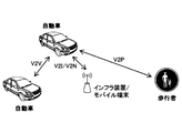
- V2X is a part of ITS (Intelligent Transport Systems), and as shown in FIG. 1, V2V (Vehicle to Vehicle), which means a communication mode between automobiles, is installed on the side of an automobile and a road.
- V2I Vehicle to Infrastructure
- RSU Road-Side Unit
- V2N Vehicle to
- Nomadic device and V2P (Vehicle to Pedestrian), which means a communication mode between a car and a pedestrian mobile terminal.
- the terminal on the transmitting side transmits HARQ-ACK corresponding to HARQ-ACK of the side link to the base station (gNB). More specifically, for example, the base station schedules the terminal, and the transmitting terminal transmits data to the receiving terminal by PSCCH / PSCH.
- the receiving terminal provides feedback on PSCCH / PSCH data transmission to the transmitting terminal, and based on this, the transmitting terminal provides HARQ-ACK feedback to the base station 10.
- a receiving unit that receives a signal from a base station and a periodic side link resource for transmitting data on the side link are set based on the signal received by the receiving unit.
- an uplink control channel resource for transmitting the first HARQ-ACK corresponding to the Hybrid Automatic Repeat Request (HARQ) -Acknowledgement (ACK) of the side link communication received by the receiving unit is set to the base station.
- a terminal is provided that includes a control unit that performs the first HARQ-ACK, and a transmission unit that transmits the first HARQ-ACK with the resources of the uplink control channel set by the control unit.
- the operation when the HARQ-ACK is transmitted from the terminal to the base station is clarified.
- V2X It is a figure for demonstrating V2X. It is a figure for demonstrating the side link. It is a figure for demonstrating the side link. It is a figure for demonstrating the MAC PDU used for side link communication. It is a figure for demonstrating the format of SL-SCH subhader. It is a figure for demonstrating the example of the channel structure used in the side link in LTE-V2X. It is a figure which shows the configuration example of the wireless communication system which concerns on embodiment. It is a figure for demonstrating the resource selection operation of a terminal. It is a figure which shows the outline of SL transmission mode 1 defined by V2X of NR. It is a figure which shows the outline of SL transmission mode 2a.
- the method of direct communication between terminals in the present embodiment is assumed to be LTE or NR side link (SL (Sidelink)), but the method of direct communication is not limited to this method.
- SL Sidelink
- the name "side link” is an example, and the name “side link” may not be used, and UL (Uplink) may include the function of SL.
- SL may be distinguished from DL (Downlink) or UL by the difference in frequency or time resource, or may have another name.
- UL and SL refer to a time resource, a frequency resource, a time / frequency resource, a reference signal for determining Pathloss in transmission power control, and a reference signal (PSS / SSS / PSSS / SSSS) used for synchronization. ) May be distinguished by the difference in any one or a plurality of combinations.
- the reference signal of antenna port X_ANT is used as a reference signal to be referred to in determining Pathloss in transmission power control, and in SL (including UL used as SL), Pathloss is determined in transmission power control.
- the reference signal to be referred to the reference signal of the antenna port Y_ANT is used.
- a terminal which may be called a user device (UE)
- UE user device
- the embodiment of the present invention is not limited to this mode.
- the terminal may be a terminal held by a person, the terminal may be a device mounted on a drone or an aircraft, and the terminal may be a base station, an RSU, a relay station (relay node), or a scheduling ability. It may be a user device or the like.
- side link is used as the basic technology
- the outline of the side link will be described as a basic example.
- An example of the technique described here is 3GPP Rel. This is the technology specified in 14 mag.
- the technique may be used in the NR, or a technique different from the technique may be used in the NR.
- side-link communication may be defined as direct communication performed between two or more adjacent user devices while using E-UTRA technology without going through a network node.
- Sidelinks may be defined as interfaces between user devices in sidelink communication.
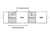
- a resource pool for the Discovery message is set (configured) for each Discovery period, and the terminal (referred to as the UE) is the Discovery message (discovery signal) in the resource pool. ) Is sent. More specifically, there are Type1 and Type2b.
- Type 1 the terminal autonomously selects a transmission resource from the resource pool.
- Type2b quasi-static resources are allocated by upper layer signaling (for example, RRC signal).
- a resource pool for SCI (Sidelink Control Information) / data transmission is periodically set for each SC (Sidelink Control) period.
- the terminal on the transmitting side notifies the receiving side of the data transmission resource (PSSCH resource pool) or the like by SCI with the resource selected from the Control resource pool (PSCCH resource pool), and transmits the data with the data transmission resource.
- PSSCH resource pool data transmission resource
- PSCCH resource pool Control resource pool
- Rel-14 in addition to mode 1 and mode 2, there are mode 3 and mode 4.
- SCI and data can be transmitted simultaneously (in one subframe) in resource blocks adjacent in the frequency direction.
- SCI may be referred to as SA (scheduling association).
- PSDCH Physical Sidelink Discovery Channel
- PSCCH Physical Sidelink Control Channel
- PSCCH Physical Sidelink Control Channel
- PSSCH Physical Sidelink Shared Channel
- PSCCH and PSSCH have a PUSCH-based structure, and have a structure in which DMRS (Demodulation Reference Signal, demodulation reference signal) is inserted.
- PSCCH may be referred to as a side link control channel
- PSCCH may be referred to as a side link shared channel.
- the signal transmitted via the PSCCH may be referred to as a sidelink control signal
- the signal transmitted via the PSCCH may be referred to as a sidelink data signal.
- the MAC (Medium Access Control) PDU (Protocol Data Unit) used for the side link is composed of at least a MAC header, a MAC Control element, a MAC SDU (Service Data Unit), and Padding.
- the MAC PDU may contain other information.
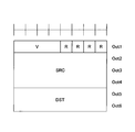
- the MAC header is composed of one SL-SCH (Siderink Sharped Channel) subheader and one or more MAC PDU subheaders.
- the SL-SCH subheader is composed of a MAC PDU format version (V), source information (SRC), destination information (DST), Reserved bit (R), and the like.
- V is assigned to the beginning of the SL-SCH subheader and indicates the MAC PDU format version used by the terminal.
- Information about the sender is set in the sender information.
- An identifier related to the ProSe UE ID may be set in the source information.
- Information about the destination is set in the destination information. In the destination information, information related to the ProSe Layer-2 Group ID of the destination may be set.
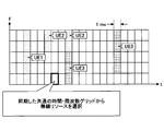
- FIG. 5 shows an example of the side link channel structure in LTE-V2X.
- the PSCCH resource pool and the PSCH resource pool used for "communication” are assigned.
- the PSDCH resource pool used for "discovery” is allocated in a cycle longer than the cycle of the "communication" channel. Note that PSDCH may not be included in NR-V2X.
- PSSS Primary Sidelink Synchronization signal
- SSSS Secondary Sidelink Synchronization signal
- PSBCH Physical Sidelink Broadcast Channel
- PSSS / SSSS and PSBCH are transmitted, for example, in one subframe.
- PSSS / SSSS may be referred to as SLSS.
- V2X assumed in this embodiment is a method related to "communication”. However, in the present embodiment, it may be assumed that there is no distinction between “communication” and “discovery”. In addition, the technique according to this embodiment may be applied in "discovery”.
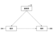
- FIG. 6 is a diagram showing a configuration example of a wireless communication system according to the present embodiment.
- the wireless communication system according to the present embodiment includes a base station 10, a terminal 20A, and a terminal 20B. Although there may actually be a large number of terminals, FIG. 6 shows terminals 20A and 20B as examples.
- the terminal 20A is intended to be the transmitting side and the terminal 20B is intended to be the receiving side, but both the terminal 20A and the terminal 20B have both a transmitting function and a receiving function.
- terminal 20 when the terminals 20A, 20B and the like are not particularly distinguished, they are simply described as "terminal 20" or "terminal".
- FIG. 6 shows a case where both the terminal 20A and the terminal 20B are within the coverage as an example, but the operation in the present embodiment is a case where all the terminals 20 are within the coverage and a case where some terminals 20 are within the coverage. It can be applied to both the case where it is in coverage and the other terminal 20 is out of coverage, and the case where all terminals 20 are out of coverage.
- the terminal 20 is, for example, a device mounted on a vehicle such as an automobile, and has a cellular communication function as a UE in LTE or NR and a side link function. Further, the terminal 20 includes a function of acquiring report information (position, event information, etc.) such as a GPS device, a camera, and various sensors. Further, the terminal 20 may be a general mobile terminal (smartphone or the like). Further, the terminal 20 may be an RSU. The RSU may be a UE type RSU having a UE function, a BS type RSU having a base station function (may be called a gNB type UE), or a relay station.
- the RSU may be a UE type RSU having a UE function, a BS type RSU having a base station function (may be called a gNB type UE), or a relay station.
- the terminal 20 does not have to be a device in one housing.
- the device including the various sensors is the terminal 20.
- the terminal 20 may be provided with a function of transmitting and receiving data to and from various sensors without including various sensors.
- the processing content of the side link transmission of the terminal 20 is basically the same as the processing content of the UL transmission in LTE or NR.
- the terminal 20 scrambles and modulates a codeword of transmission data to generate complex-valued symbols, maps the complex-valued symbols (transmission signal) to one or two layers, and performs precoding. Then, the precoded complex-valued symbols are mapped to the resource element to generate a transmission signal (eg, CP-OFDM, DFT-s-OFDM), which is transmitted from each antenna port.
- a transmission signal eg, CP-OFDM, DFT-s-OFDM
- the base station 10 a function of cellular communication as the base station 10 in LTE or NR and a function for enabling communication of the terminal 20 in the present embodiment (example: resource pool setting, resource allocation, etc.) )have.
- the base station 10 may be an RSU (gNB type RSU), a relay station, or a terminal having a scheduling function.
- RSU gNB type RSU
- the signal waveform used by the terminal 20 for SL or UL may be OFDMA, SC-FDMA, or other signal waveform. You may.
- a frame composed of a plurality of subframes (example: 10 subframes) is formed in the time direction, and a frame composed of a plurality of subcarriers is formed in the frequency direction.
- TTI Transmission Time Interval
- TTI is not always a subframe.
- TTI may be a slot or mini-slot or other time domain unit.
- the number of slots per subframe may be determined according to the subcarrier interval. Further, the number of symbols per slot may be 14 symbols.
- the terminal 20 is in mode 1, in which resources are dynamically allocated by (E) PDCCH ((Enhanced) Physical Downlink Control Channel) sent from the base station 10 to the terminal, and the terminal autonomously resources.
- Mode 2 which is a mode for selecting transmission resources from the pool, mode in which resources for SL signal transmission are allocated from the base station 10 (hereinafter referred to as mode 3), and resources for SL signal transmission are autonomously selected.
- mode 3 mode in which resources for SL signal transmission are allocated from the base station 10
- mode 4 Any mode of the mode (hereinafter referred to as mode 4) can be taken.
- the mode is set, for example, from the base station 10 to the terminal 20.
- the mode 4 terminal selects a radio resource from a synchronized common time / frequency grid.
- the terminal 20 performs sensing in the background, identifies a resource having a good sensing result and is not reserved for another terminal as a candidate resource, and selects a resource to be used for transmission from the candidate resources. To do.
- V2X of NR the same transmission mode as SL transmission mode 3 and SL transmission mode 4 defined in LTE V2X is defined.
- the transmission mode may be read as a resource allocation mode, and the name is not limited to this.
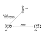
- FIG. 8A is a diagram showing an outline of SL transmission mode 1 defined by V2X of NR.
- the SL transmission mode 1 specified by V2X of NR corresponds to the SL transmission mode 3 specified by V2X of LTE.
- the base station 10 schedules transmission resources and allocates transmission resources to the transmission side terminal 20A.
- the terminal 20A transmits a signal to the receiving terminal 20B by the allocated transmission resource.
- FIGS. 8B, 8C, and 8D are diagrams showing an outline of SL transmission mode 2 defined by V2X of NR.
- the SL transmission mode 2 specified by V2X of NR corresponds to the SL transmission mode 4 specified by V2X of LTE.
- FIG. 8B is a diagram showing an outline of SL transmission mode 2a.
- the transmission side terminal 20A autonomously selects a transmission resource, and the selected transmission resource transmits a signal to the reception side terminal 20B.
- FIG. 8C is a diagram showing an outline of SL transmission mode 2c.
- the base station 10 sets a transmission resource with a fixed cycle in advance for the terminal 20A, and the terminal 20A receives a signal by the transmission resource with a fixed cycle set in advance. It is transmitted to the terminal 20B of.
- the base station 10 instead of the base station 10 presetting the transmission resource of the fixed cycle for the terminal 20A, for example, even if the transmission resource of the fixed cycle is set in advance for the terminal 20A according to the specifications. Good.
- FIG. 8D is a diagram showing an outline of SL transmission mode 2d.
- the terminal 20 performs the same operation as the base station 10. Specifically, the terminal 20 schedules the transmission resource and allocates the transmission resource to the transmission side terminal 20A. The terminal 20A may transmit to the receiving terminal 20B by the allocated communication resource. That is, the terminal 20 may control the transmission of another terminal 20.
- NR As shown in FIGS. 9A to 9C, three types of communication, unicast, group cast, and broadcast, are currently under consideration.
- FIG. 9A is a diagram showing an example of unicast Physical Sidelink Sharp Channel (PSCCH) / Physical Sidelink Control Channel (PSSCH) transmission.
- Unicast means, for example, one-to-one transmission from the transmitting side terminal 20A to the receiving side terminal 20B.
- FIG. 9B is a diagram showing an example of group cast PSCCH / PSCH transmission.
- the group cast means, for example, transmission from the transmitting side terminal 20A to the terminal 20B and the terminal 20B'which are a group of the receiving side terminal 20.
- FIG. 9C is a diagram showing an example of broadcast PSCCH / PSCH transmission.
- Broadcast refers to, for example, transmission from terminal 20A on the transmitting side to all terminals 20 on the receiving side within a predetermined range, terminal 20B, terminal 20B', and terminal 20B''.
- New Radio (NR) -Sidelink (SL) of Release 16 of the Third Generation Partnership Project (3GPP) is expected to support Hybrid Automatic Repeat Request (HARQ) feedback.
- NR New Radio
- SL idelink
- HARQ Hybrid Automatic Repeat Request
- CG composite grant
- the base station 10 sets periodic sidelink radio resources (time and frequency resources) for the terminal 20, and the terminal 20 uses the set periodic sidelink radio resources.
- Data can be transmitted to the terminal 20 on the receiving side.
- NR-Uu an interface between a 5G user device and a 5G Radio Access Network (RAN)
- RAN 5G Radio Access Network
- periodic radio resources are set for the terminal 20 (quasi-statically) by the parameters of the upper layer, and the terminal 20 is set without receiving the DCI for allocating the radio resources.
- Data can be transmitted using periodic radio resources.
- the radio resource may be available until the setting is changed by RRC-recomposition.
- a periodic radio resource is set for the terminal 20 by a parameter of the upper layer, and the terminal 20 activates or deactivates the periodic radio resource based on the received Downlink Control Information (DCI). (Release) can be performed.
- DCI Downlink Control Information
- Type 1 CG and Type 2 CG are also applied to NR side-link communication.
- HARQ-ACK Hybrid Automatic Repeat Request
- PSFCH Physical Sidelink Feedback Channel
- PSCCH Physical Sidelink Control Channel
- PSSCH Physical Sidelink Shared Channel
- Send HARQ-ACK As shown in FIG. 10, PSFCH may be mapped to one or more symbols at the end with respect to slot time. Since PSFCH resources are associated with PSCCH and / or PSSCH in the time domain, it may not be expected that PSFCH resources will be dynamically specified in the time domain. Moreover, the resource determination method of PSFCH is not limited to this.
- the transmitting terminal 20 transmits the side link HARQ-ACK to the base station 10 (gNB) as shown in FIG. .. More specifically, for example, as shown in FIG. 11, the base station 10 schedules the terminal # A, and the terminal # A transmits data to the terminal # B by PSCCH / PSSCH. Terminal # B provides feedback on PSCCH / PSCH data transmission to terminal # A, and based on this, terminal # A provides feedback on HARQ-ACK to base station 10.
- the present invention is not limited to this, and is also applicable to the case where the terminal # B gives the HARQ-ACK feedback to the base station 10.
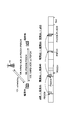
- FIG. 12 is a diagram showing an example in the case where the configured grant is applied and HARQ is applied in SL transmission mode 1.
- the base station 10 sets a configured grant (CG) for the terminal #A.
- the terminal #A transmits data (for example, a transport block) to the terminal #B with the PSCCH / PSSCH resource corresponding to the set CG.
- terminal # B transmits HARQ-ACK for the data transmission in step 102 to terminal # A by PSFCH.
- terminal #A transmits HARQ-ACK to base station 10. Steps 102 to 104 are repeated based on the periodic resources set in step 101. Further, activation of CG by DCI may be added between step 101 and step 102. Here, it is necessary to determine the resources in the time domain and the frequency domain when transmitting the HARQ-ACK in step 104.
- Proposal A proposes a method of designating a resource of the Physical Uplink Control Channel (PUCCH) when the terminal #A transmits HARQ-ACK to the base station 10 in step 104 of FIG. That is, in the proposal A, a method of designating the PUCCH resource in the slot in which the terminal #A transmits HARQ-ACK is proposed.
- the slot for transmitting HARQ-ACK by the terminal #A may be specified by a method described later or another method.
- terminal #A may transmit HARQ-ACK to the base station 10 with the PUCCH resource (or the corresponding PUSCH resource) set by the parameter of the upper layer.
- the base station 10 transmits DCI to the terminal 20 to periodically activate or deactivate the radio resource.
- the transmission of HARQ-ACK from the terminal 20 for the data (for example, transport block) communication in the CG resource immediately after the transmission of the DCI from the base station 10 may be excluded from the target of the proposal A, and the proposal It may be included in A. That is, when excluded, it may be assumed that the terminal 20 transmits HARQ-ACK with the PUCCH resource specified by the DCI.
- a method similar to the downlink semi-persistent scheduling (DL SPS) in the NR of Release 15 may be applied.
- DL SPS downlink semi-persistent scheduling
- PUCCH-ReachyId for transmitting HARQ-ACK corresponding to data transmission in the transmission resource set by SPS-Config is set by n1PUCCH-AN included in SPS-Config. It is specified.
- the base station 10 may set a Configured GrantConfig-sidelink including at least one n1PUCCH-AN as a parameter of the upper layer.
- Configured Grant Config-sidelink may be a parameter for setting the configured grant of the side link for the terminal 20.
- the name ConfiguredGrantConfig-sidelink is an example, and the name of the parameter for setting the sidelink configured grant for the terminal 20 is not limited to this example.
- the base station 10 may include n1PUCCH-AN and one of the following parameters in the Configured GrantConfig-sidelink.
- the parameter name included in the ConfiguredGrantConfig-sidelink is an example, and the name is not limited to this.
- Uci-OnPUSCH Indicates the value of beta-offset in the case of Uci-OnPUSCH ⁇ Configured GrantTimer
- the n1PUCCH-AN included in the ConfiguredGrantConfig-sidelink may specify the PUCCH-ResourceId for transmitting the HARQ-ACK corresponding to the transmission of data in the resource set by the ConfigureGrantConfig-sidelink, and is linked to some PUCCH resource. It may be attached.
- PUCCH-ValueId of PUCCH form0 or PUCCHformat1 may be specified. In this case, for example, the following conditions may be added. -When the transmission of PSCH (transport block) based on the code block group (CBG) is not set / instructed, and / or the transmission of PSCH based on CBG is set, but the PSCH transmitted on the CG resource of the side link. When the HARQ-ACK bit corresponding to is up to 2 bits and / or when each HARQ-ACK corresponding to the PSCH of the side link CG resource is transmitted separately to the base station 10, n1PUCCH-AN May specify PUCCH-ResourceId of PUCCH form0 or PUCCH form1. -In cases other than the above, n1PUCCH-AN may specify PUCCH-ResourceId of PUCCH format2, PUCCHformat3, or PUCCHformat4.
- n1PUCCH-AN-1 and n1PUCCH-AN-2 may be specified as n1PUCCH-AN.
- n1PUCCH-AN-1 may specify PUCCH-ReachyId of PUCCH format0 or PUCCH format1 (that is, PUCCH format capable of transmitting up to 2 bits). Good.
- n1PUCCH-AN-2 is PUCCH of PUCCH form2, PUCCHformat3, or PUCCHformat4 (that is, PUCCH format capable of transmitting 3 bits or more).
- -ResourceId may be specified.
- the transmission of PSCH based on the code block group (CBG) is not set / instructed, and / or the transmission of PSCH based on CBG is set, but HARQ-ACK corresponding to the PSCH of the CG resource of the side link.
- CBG code block group
- the n1PUCCH-AN-1 is configured as a Defined GrantConfig-. It may be used to transmit HARQ-ACK corresponding to data transmission with the resource set by sidelink. In cases other than the above, n1PUCCH-AN-2 may be used to transmit the HARQ-ACK corresponding to the data transmission with the resource set by the Configured GrantConfig-sidelink.
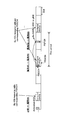
- FIG. 13 is a diagram showing an example of Proposal A.
- the base station 10 sets the configured grant (CG) by transmitting the parameter Configured GrantConfig-sidelink of the upper layer including n1PUCCH-AN to the terminal #A.
- the terminal #A transmits data to the terminal #B with the PSCCH / PSSCH resource corresponding to the set CG.
- the terminal #B transmits HARQ-ACK for the data transmission in step 202 to the terminal #A by PSFCH.
- terminal # A transmits HARQ-ACK to base station 10.
- the terminal #A transmits HARQ-ACK to the base station 10 by using the PUCCH resource specified by n1PUCCH-AN included in the ConfiguredGrantConfig-sidelink transmitted in step 201.
- the HARQ-ACK bit corresponding to the data (for example, transport block) communication in the CG resource immediately after the transmission of the DCI for the periodic activation of the radio resource of the side link is the HARQ corresponding to the DL transmission. It may be multiplexed with the -ACK bit and / or the HARQ-ACK bit corresponding to side link communication in resources other than CG. Since the PUCCH resource for multiple transmission is the resource specified by the last DCI, HARQ corresponding to data (for example, transport block) communication in the CG resource immediately after the transmission of the DCI for the activation is performed. It is desirable that the transmission of the -ACK bit be dynamically instructed based on the DCI.
- the transmission of the HARQ-ACK bit corresponding to the data (for example, transport block) communication in the CG resource other than the CG resource immediately after the transmission of the DCI for the activation is the transmission of the HARQ-ACK corresponding to the DL transmission.
- the last DCI is a DCI other than the activation DCI, so no dynamic instruction is required. .. Therefore, it is possible to apply the method of Proposal A so that the PUCCH resource to be used can be specified by a different method depending on whether or not it is immediately after the periodic activation of the radio resource of the side link.
- Provision B A resource for transmitting HARQ-ACK from the terminal 20 to the base station 10 as a PUCCH resource (or a PUSCH resource corresponding to the PUCCH) specified by DCI for activating the periodic radio resource of the side link. You may use it continuously.
- Proposal B is applied to Type 2 CG and Proposal A is applied to Type 1 CG. It may be applied to CG.
- the DCI for periodic activation of radio resources on the sidelinks may specify one PUCCH resource from the PUCCH resource set.
- the PUCCH resource specified by the DCI may be used as a resource for transmitting HARQ-ACK from the terminal 20 to the base station 10.
- the PUCCH resource set is the same as the PUCCH resource set used to transmit the HARQ-ACK for the data (eg, transport block) transmitted by the sidelink's dynamically scheduled resource. It may be the same as or different from the PUCCH resource set used to transmit the HARQ-ACK for DL transmission.
- FIG. 14 is a diagram showing an example of Proposal B.
- the base station 10 transmits a parameter of the upper layer Configured GrantConfig-sidelink to the terminal #A to set the configured grant (CG), and for CG activation.
- a DCI which is a DCI and includes a PUCCH resource indicator, is transmitted to the terminal #A.
- the terminal #A transmits data to the terminal #B using the PSCCH / PSSCH resources corresponding to the set CG.
- terminal # B transmits HARQ-ACK for the data transmission in step 302 to terminal # A by PSFCH.
- terminal # A transmits HARQ-ACK to base station 10.
- the terminal #A transmits HARQ-ACK to the base station 10 by using the PUCCH resource specified by the PUCCH resource indicator included in the DCI transmitted in step 301.
- PUCCH resources can be specified more flexibly. Further, according to the method of Proposal B, since the PUCCH resource can be specified more flexibly, for example, HARQ-ACK for transmission by CG of the side link is set to other HARQ-ACK (for example, NR-). This is effective when transmitting to the base station 10 without multiplexing with Uu's HARQ-ACK).
- HARQ-ACK for transmission by CG of the side link is set to other HARQ-ACK (for example, NR-). This is effective when transmitting to the base station 10 without multiplexing with Uu's HARQ-ACK).
- the terminal 20 does not have to transmit the HARQ-ACK corresponding to the data transmission, which is the data transmission by the side link CG resource and does not accompany the corresponding PDCCH, to the base station 10.
- the terminal 20 uses the PDCCH to perform HARQ-ACK corresponding to data transmission with the CG resource of the side link corresponding to the PDCCH (for example, DCI for the periodic activation of the radio resource of the side link). It may be transmitted by the designated PUCCH resource (or the PUSCH resource corresponding to the PUCCH resource).
- FIG. 15 is a diagram showing an example of Proposal C.
- FIG. 15 shows that the terminal 20A does not transmit the HARQ-ACK corresponding to the data transmission, which is the data transmission by the side link CG resource and does not accompany the corresponding PDCCH, to the base station 10.
- the terminal 20 transmits the data (for example, the transport block) by the CG resource of the side link, and performs the HARQ-ACK corresponding to the data transmission without the corresponding PDCCH as the base station.
- the terminal 20 transmits the data (for example, the transport block) by the CG resource of the side link, and performs the HARQ-ACK corresponding to the data transmission without the corresponding PDCCH as the base station.
- the terminal 20 transmits the data (for example, the transport block) by the CG resource of the side link, and performs the HARQ-ACK corresponding to the data transmission without the corresponding PDCCH as the base station.
- Proposal D The terminal 20 transmits the HARQ-ACK corresponding to the data transmission, which is the data transmission by the CG resource of the side link and is not accompanied by the corresponding PDCCH, by the PUCCH resource included in the slot designated by the base station 10.
- Proposal D is a method of designating a slot for transmitting the HARQ-ACK, and the method of designating the PUCCH resource in the slot may be Proposal A and / or Proposal B, or another method. Good.
- the slot to be transmitted by the same method may be specified.
- the base station 10 and the terminal 20 it is possible for the base station 10 and the terminal 20 to have a common recognition about the timing (for example, slot) of transmitting HARQ-ACK, and the data in the CG resource (for example, a transformer) can be shared. It becomes possible to appropriately transmit HARQ-ACK for transmission (port block) to the base station 10.
- the terminal 20 is a PUCCH resource included in a slot designated by DCI for the periodic activation of the radio resource of the side link, which is data transmission by the CG resource of the side link and is not accompanied by a corresponding PDCCH.
- Data transmission, HARQ-ACK may be transmitted to the base station 10.
- FIG. 16 is a diagram showing an example of Proposal D.
- the terminal 20 performs PSCCH / PSCH transmission with the CG resource of the side link, and PSCCH / PSCH transmission without the corresponding PDCCH, in slot n.
- the terminal 20 may transmit the HARQ-ACK corresponding to the PSCCH / PSCH transmission to the base station 10 by the PUCCH (or the corresponding PUSCH) included in the slot n + k.
- k may be specified in the PSCCH-to-HARQ-timing indicator field or PSCH-to-HARQ-timing indicator field included in the DCI format for the periodic activation of radio resources on the sidelinks. ..
- FIG. 17 is a diagram showing another example of Proposal D.
- the terminal 20 is a PSCCH / PSCH transmission with the CG resource of the side link, and the PSCCH / PSCH transmission without the corresponding PDCCH is received by the PSFCH (side from the terminal 20B). It is assumed that HARQ-ACK reception of the link) is performed in slot n.
- the terminal 20 may transmit the HARQ-ACK corresponding to the PSCCH / PSCH transmission to the base station 10 by the PUCCH (or the corresponding PUSCH) included in the slot n + k.
- k may be specified in the PSFCH-to-HARQ-timing indicator field included in the DCI format for periodic activation of radio resources on the sidelinks.
- FIG. 18 is a diagram showing another example of Proposal D.
- the terminal 20 receives a DCI in slot n for periodic activation of radio resources on the sidelinks.
- the terminal 20 may transmit the HARQ-ACK corresponding to the PSCCH / PSCH transmission in the slot n + k + P ⁇ N.
- k may be specified in the PDCCH-to-HARQ-timing indicator field included in the DCI format for the periodic activation of radio resources on the sidelinks.
- P may be the CG cycle of the side link.
- N may be the number of transmission opportunities in the sidelink CG resource after activation. Note that N may specify the number of transmission opportunities in the time direction.
- N may specify the number of transmission opportunities in the time and frequency directions (which may be subchannels) (in this case, the formula indicating the slot above may be modified as appropriate).
- the slot may be a slot in which an offset value is added to the above n + k + P ⁇ N.
- the terminal 20 is a PUCCH resource included in the slot specified by the parameter of the upper layer, and performs HARQ-ACK corresponding to data transmission, which is data transmission by the CG resource of the side link and is not accompanied by the corresponding PDCCH. , May be transmitted to the base station 10.
- the terminal 20 may transmit the HARQ-ACK corresponding to the PSCCH / PSCH transmission to the base station 10 with the PUCCH resource (or the corresponding PUSCH resource) included in the slot n + k.
- k may be specified by a parameter of the upper layer.
- the terminal 20 is a PSCCH / PSCH transmission with the CG resource of the side link, and is received by the PSFCH for the PSCCH / PSCH transmission without the corresponding PDCCH (reception of the HARQ-ACK of the side link from the terminal 20B). Is assumed to be performed in slot n. In this case, the terminal 20 may transmit the HARQ-ACK corresponding to the PSCCH / PSCH transmission to the base station 10 with the PUCCH resource (or the corresponding PUSCH resource) included in the slot n + k.
- k may be specified by a parameter of the upper layer.
- the base station 10 recognizes that the terminal 20 does not transmit the side link channel with the side link CG resource. Can't. In this case, if the terminal 20 does not transmit the HARQ-ACK, the base station 10 may erroneously determine that the reception of the HARQ-ACK has failed. In such a case, the base station 10 may determine that the reception of the negative acquired generation (NACK) has failed, and dynamically allocate the additional side link resource to the terminal 20. However, the terminal 20 merely does not transmit the side link channel with the CG resource of the side link, and allocation of such an additional side link resource is unnecessary. In order to prevent such unnecessary allocation of sidelink resources, the method of Proposal E can be applied.
- the terminal 20 When the terminal 20 does not transmit the side link channel with the side link CG resource, the terminal 20 is an acknowledgment (Acknowledgement (ACK)) as HARQ-ACK with the set PUCCH resource or the specified PUCCH resource. May be sent.
- ACK Acknowledgement
- FIG. 19 is a diagram showing an example of Proposal E1.
- the base station 10 transmits the parameter Configured GrantConfig-sidelink of the upper layer to the terminal #A to set the configured grant (CG), and is a DCI for CG activation, which is a PUCCH resource indicator.
- DCI including, is transmitted to terminal # A.
- the terminal #A does not transmit the side link data to the terminal 20B because, for example, there is no data to be transmitted. Therefore, in step 402, terminal #A transmits an acknowledgment (ACK) to the base station 10 as HARQ-ACK with the PUCCH resource specified by DCI.
- ACK acknowledgment
- different carriers may be applied to Uu and the side link.
- different numerologies may be applied to Uu and sidelinks in the above embodiments.
- the parameters n, k, P, N in the above-described embodiment are set with reference to Uu.
- the side link it is conceivable to set the side link as a reference.
- the parameters n, k, P, N in the above-described embodiment may be set based on the carrier of PUCCH. For example, when the subcarrier interval (SCS) of the PSCCH / PSCH carrier is larger than the subcarrier interval of the PUCCH carrier, the HARQ-ACK of the PSCCH / PSCH with a large subcarrier interval is larger than the subcarrier interval of the PSCCH / PSCH.
- SCS subcarrier interval
- the HARQ-ACK of the PSCCH / PSCH having a small subcarrier interval is the subcarrier of the PSCCH / PSCH.
- the parameters n, k, P, N in the above-described embodiment may be set based on the carrier of PSCCH / PSCH.
- the parameters n, k, P, N in the above-described embodiment may be set based on the carrier of PSFCH.
- the parameters n, k, P, N in the above-described embodiment may be set based on the carrier of PDCCH.
- FIG. 20 is a diagram showing an example of the functional configuration of the base station 10.
- the base station 10 has a transmitting unit 101, a receiving unit 102, and a control unit 103.
- the functional configuration shown in FIG. 20 is only an example. Any function classification and name of the functional unit may be used as long as the operation according to the present embodiment can be executed.
- the transmitter 101 may be referred to as a transmitter, and the receiver 102 may be referred to as a receiver.
- the transmission unit 101 includes a function of generating a signal to be transmitted to the terminal 20 side and transmitting the signal wirelessly.
- the receiving unit 102 includes a function of receiving various signals transmitted from the terminal 20 and acquiring, for example, information of a higher layer from the received signals.
- the receiving unit 102 includes a function of measuring the received signal and acquiring a quality value.
- the control unit 103 controls the base station 10.
- the function of the control unit 103 related to transmission may be included in the transmission unit 101, and the function of the control unit 103 related to reception may be included in the reception unit 102.
- control unit 103 of the base station 10 sets a periodic resource (configured grant (CG)) for the side link communication in the terminal 20, and sets a periodic resource for the side link communication. Is created, and the transmission unit 101 transmits the message to the terminal 20.
- CG configured grant
- the control unit 103 of the base station 10 transmits HARQ-ACK to the base station 10 in the slot.
- the parameters of the upper layer for designating the PUSCH resource for the purpose may be created, and the transmission unit 101 may transmit the parameters of the upper layer to the terminal 20.
- control unit 103 of the base station 10 provides the DCI for the periodic activation of the radio resource of the side link with information for designating the PUCCH resource for the terminal 20 to transmit the HARQ-ACK to the base station 10.
- the transmission unit 101 may transmit the DCI to the terminal 20.
- control unit 103 of the base station 10 creates a parameter of the upper layer for specifying the PUCCH resource for transmitting the HARQ-ACK to the base station 10 in the slot for the CG of Type 1, and transmits it.
- the unit 101 is made to transmit the parameters of the upper layer to the terminal 20, and the control unit 103 of the base station 10 is used for the CG of the type 2 to the DCI for the periodic activation of the radio resource of the side link.
- the transmission unit 101 may be made to transmit the DCI to the terminal 20, including the information specifying the PUCCH resource for the terminal 20 to transmit the HARQ-ACK to the base station 10.
- control unit 103 of the base station 10 causes the terminal 20 to transmit the HARQ-ACK corresponding to the data transmission using the side-link CG resource without the corresponding PDCCH to the base station 10.
- a slot for the purpose and a PUCCH resource included in the slot may be set.
- FIG. 21 is a diagram showing an example of the functional configuration of the terminal 20.
- the terminal 20 has a transmission unit 201, a reception unit 202, and a control unit 203.
- the functional configuration shown in FIG. 21 is only an example. Any function classification and name of the functional unit may be used as long as the operation according to the present embodiment can be executed.
- the transmitter 201 may be referred to as a transmitter, and the receiver 202 may be referred to as a receiver.
- the terminal 20 may be the transmitting side terminal 20A or the receiving side terminal 20B. Further, the terminal 20 may be a scheduling terminal 20.
- the transmission unit 201 creates a transmission signal from the transmission data and wirelessly transmits the transmission signal.
- the receiving unit 202 wirelessly receives various signals and acquires a signal of a higher layer from the received signal of the physical layer. Further, the receiving unit 202 includes a function of measuring the received signal and acquiring a quality value.
- the control unit 203 controls the terminal 20.
- the function of the control unit 203 related to transmission may be included in the transmission unit 201, and the function of the control unit 203 related to reception may be included in the reception unit 202.
- the receiving unit 202 of the terminal 20 includes an upper layer parameter including the setting information of the configured grant (CG) which is the setting information of the resource for the periodic data transmission of the side link transmitted from the base station 10.
- CG configured grant
- the control unit 203 of the base station 10 sets the CG according to the CG setting information included in the parameters of the received upper layer, and the transmission unit 201 of the base station 10 uses the set CG resources. Then, the side link data is transmitted.
- the receiving unit 202 of the terminal 20 transmits HARQ-ACK to the base station 10 when the terminal 20 specifies a slot for transmitting the HARQ-ACK to the base station 10. It may receive higher layer parameters that include information that specifies the resources of the PUCCH of.
- the control unit 203 of the terminal 20 creates a HARQ-ACK corresponding to the HARQ-ACK of the side link to be transmitted to the base station 10.
- the transmission unit 201 of the terminal 20 transmits the HARQ-ACK corresponding to the HARQ-ACK of the side link to the base station 10 using the PUCCH resource specified by the information included in the parameters of the upper layer. You may.
- the receiving unit 202 of the terminal 20 receives the DCI for activating the resource for the periodic data transmission of the side link, and the control unit 203 of the terminal 20 receives the PUCCH resource specified by the DCI. , It may be set as a resource for transmitting HARQ-ACK from the terminal 20 to the base station 10.
- control unit 203 of the terminal 20 is for the terminal 20 designated by the parameters of the upper layer received from the base station 10 by the receiving unit 202 to transmit HARQ-ACK to the base station 10 with respect to the CG of Type 1.
- a PUCCH resource may be set, and the transmission unit 201 of the terminal 20 may transmit HARQ-ACK to the base station 10 using the set PUCCH resource.
- the control unit 203 of the terminal sets the terminal 20 to the CG of Type 2 according to the information contained in the DCI for activating the periodic radio resource of the side link received from the base station 10 by the receiving unit 202.
- a PUCCH resource for transmitting HARQ-ACK to the base station 10 may be set, and the transmission unit 201 of the terminal 20 may transmit the HARQ-ACK to the base station 10 using the set PUCCH resource.
- control unit 203 of the terminal 20 does not transmit the HARQ-ACK corresponding to the data transmission, which is the data transmission by the CG resource of the side link and does not accompany the corresponding PDCCH, to the base station 10. May be determined.
- the control unit 203 of the terminal 20 uses the CG resource of the side link to transmit data, and uses the base as a resource for transmitting HARQ-ACK corresponding to the data transmission without the corresponding PDCCH to the base station 10.
- the PUCCH resource included in the slot designated by the station 10 may be set.
- the control unit 203 of the terminal 20 when the base station 10 sets the side link CG for the terminal 20 and / or when the side link CG resource is activated, the control unit 203 of the terminal 20 side with the side link CG resource. Regardless of whether or not the link channel is transmitted, the PUCCH resource (or the corresponding PUSCH resource) is set, and the transmission unit 201 of the terminal 20 transmits HARQ-ACK to the base station 10.
- each functional block may be realized by using one physically or logically connected device, or directly or indirectly (for example, two or more physically or logically separated devices). , Wired, wireless, etc.) and may be realized using these plurality of devices.
- the functional block may be realized by combining the software with the one device or the plurality of devices.
- Functions include judgment, decision, judgment, calculation, calculation, processing, derivation, investigation, search, confirmation, reception, transmission, output, access, solution, selection, selection, establishment, comparison, assumption, expectation, and assumption.
- broadcasting notifying, communicating, forwarding, configuring, reconfiguring, allocating, mapping, assigning, etc., but only these. I can't.
- a functional block (constituent unit) for functioning transmission is called a transmitting unit or a transmitter.
- the method of realizing each of them is not particularly limited.
- FIG. 22 is a diagram showing an example of the hardware configuration of the terminal 20 and the base station 10 according to the present embodiment.
- the terminal 20 and the base station 10 may be physically configured as a computer device including a processor 1001, a memory 1002, a storage 1003, a terminal 1004, an input device 1005, an output device 1006, a bus 1007, and the like.
- the word “device” can be read as a circuit, device, unit, etc.
- the hardware configuration of the terminal 20 and the base station 10 may be configured to include one or more of the devices shown in 1001 to 1006 shown in the figure, or may be configured not to include some of the devices. May be good.
- the processor 1001 For each function of the terminal 20 and the base station 10, the processor 1001 performs an operation by loading predetermined software (program) on the hardware such as the processor 1001 and the memory 1002, and controls the communication by the terminal 1004. It is realized by controlling at least one of reading and writing of data in the memory 1002 and the storage 1003.
- predetermined software program
- the processor 1001 operates, for example, an operating system to control the entire computer.
- the processor 1001 may be configured by a central processing unit (CPU: Central Processing Unit) including an interface with a peripheral device, a control device, an arithmetic unit, a register, and the like.
- CPU Central Processing Unit
- the processor 1001 reads a program (program code), a software module, data, etc. from at least one of the storage 1003 and the communication terminal 1004 into the memory 1002, and executes various processes according to these.
- a program program code
- a program that causes a computer to execute at least a part of the operations described in the above-described embodiment is used.
- the control unit 203 of the terminal 20 may be realized by a control program stored in the memory 1002 and operating in the processor 1001, and may be realized in the same manner for other functional blocks.
- Processor 1001 may be implemented by one or more chips.
- the program may be transmitted from the network via a telecommunication line.
- the memory 1002 is a computer-readable recording medium, and is composed of at least one such as a ROM (Read Only Memory), an EPROM (Erasable Programmable ROM), an EEPROM (Electrically Erasable Programmable ROM), and a RAM (Random Access Memory). May be done.
- the memory 1002 may be referred to as a register, a cache, a main memory (main storage device), or the like.
- the memory 1002 can store a program (program code), a software module, or the like that can be executed to implement the wireless communication method according to the embodiment of the present disclosure.
- the storage 1003 is a computer-readable recording medium, for example, an optical disk such as a CD-ROM (Compact Disc ROM), a hard disk drive, a flexible disk, a magneto-optical disk (for example, a compact disk, a digital versatile disk, a Blu-ray). It may consist of at least one (registered trademark) disk), smart card, flash memory (eg, card, stick, key drive), floppy (registered trademark) disk, magnetic strip, and the like.
- the storage 1003 may be referred to as an auxiliary storage device.
- the storage medium described above may be, for example, a database, server or other suitable medium containing at least one of memory 1002 and storage 1003.
- the communication terminal 1004 is hardware (transmission / reception device) for communicating between computers via at least one of a wired network and a wireless network, and is also referred to as, for example, a network device, a network controller, a network card, a communication module, or the like.
- the communication terminal 1004 includes, for example, a high frequency switch, a duplexer, a filter, a frequency synthesizer, etc. in order to realize at least one of frequency division duplex (FDD: Frequency Division Duplex) and time division duplex (TDD: Time Division Duplex). It may be composed of.
- FDD Frequency Division Duplex
- TDD Time Division Duplex
- the input device 1005 is an input device (for example, a keyboard, a mouse, a microphone, a switch, a button, a sensor, etc.) that receives an input from the outside.
- the output device 1006 is an output device (for example, a display, a speaker, an LED lamp, etc.) that outputs to the outside.
- the input device 1005 and the output device 1006 may have an integrated configuration (for example, a touch panel).
- each device such as the processor 1001 and the memory 1002 is connected by the bus 1007 for communicating information.
- the bus 1007 may be configured by using a single bus, or may be configured by using a different bus for each device.
- the terminal 20 and the base station 10 are hardware such as a microprocessor, a digital signal processor (DSP: Digital Signal Processor), ASIC (Application Specific Integrated Circuit), PLD (Programmable Logic Device), and FPGA (Field Programmable Gate Array), respectively. It may be configured to include hardware, and a part or all of each functional block may be realized by the hardware. For example, processor 1001 may be implemented using at least one of these hardware.
- DSP Digital Signal Processor
- ASIC Application Specific Integrated Circuit
- PLD Programmable Logic Device
- FPGA Field Programmable Gate Array
- a periodic side link resource for transmitting data on the side link is set, and the receiving unit receives the signal.
- a control unit that sets resources for an uplink control channel for transmitting a first HARQ-ACK corresponding to a Hybrid Automatic Repeat Request (HARQ) -Acknowledgement (ACK) of side link communication to the base station, and the first A terminal including a transmission unit that transmits HARQ-ACK with the resources of the uplink control channel set by the control unit.
- HARQ Hybrid Automatic Repeat Request
- ACK Acknowledgement
- HARQ-ACK is transmitted from the terminal 20 to the base station 10.
- the PUCCH resource will be explicitly specified, and the operation when HARQ-ACK is transmitted from the terminal 20 to the base station 10 will be clarified.
- the control unit may set the resource of the uplink control channel based on the identifier included in the parameter of the upper layer included in the signal received by the reception unit. Further, the control unit may set the timing of the slot including the resource of the uplink control channel based on the downlink control information received by the reception unit.
- the periodic sidelink resource is a first-class periodic sidelink resource that can be continuously used without the receiver receiving downlink control information for allocating radio resources.
- it is a second type of periodic sidelink resource that can be continuously used after activation by the control information received by the receiving unit, and the periodic sidelink resource is the first type of resource.
- the control unit sets the resource of the uplink control channel based on the identifier included in the parameter of the upper layer included in the signal received by the receiving unit, and sets the resource of the uplink control channel.
- the control unit may set the resource of the uplink control channel based on the control information.
- DCI for periodic radio resource activation of sidelinks is used only for Type 2 CG.
- Type 2 CG when transmitting HARQ-ACK from the terminal to the base station for the PUCCH resource specified by DCI for the periodic activation of the radio resource of the side link. It is possible to set it as a PUCCH resource, and in the case of Type 1 CG, set the PUCCH resource when transmitting HARQ-ACK from the terminal to the base station according to the parameters of the upper layer from the base station.
- the transmission unit is a side link resource of any one of the periodic side link resources, and when the side link data is not transmitted, the uplink control channel set by the control unit is used.
- the resource may transmit a second HARQ-ACK to the base station.
- the base station may not be able to recognize that the terminal does not transmit the side link channel with the side link CG resource. is there. In this case, if the terminal does not transmit the HARQ-ACK to the base station, the base station may erroneously determine that the reception of the HARQ-ACK has failed. In such a case, the base station may determine that the reception of the negative acquired ground (NACK) has failed and dynamically allocate the additional side link resource to the terminal.
- NACK negative acquired ground
- the terminal merely does not transmit the side link channel with the CG resource of the side link, and allocation of such an additional side link resource is unnecessary. According to the above configuration, it is possible to prevent such unnecessary allocation of sidelink resources.
- the resource of the periodic side link for transmitting data on the side link is set, and the hybrid automatic repeat request of the side link communication to be received is set.
- a method of communication by a terminal comprising a step of transmitting with a control channel resource.
- HARQ-ACK is transmitted from the terminal 20 to the base station 10.
- the PUCCH resource will be explicitly specified, and the operation when HARQ-ACK is transmitted from the terminal 20 to the base station 10 will be clarified.
- the operation of the plurality of functional units may be physically performed by one component, or the operation of one functional unit may be physically performed by a plurality of components.
- the order of processing may be changed as long as there is no contradiction.
- the terminal 20 and the base station 10 have been described with reference to functional block diagrams, but such devices may be implemented in hardware, software, or a combination thereof.
- the software operated by the processor of the terminal 20 according to the embodiment of the present invention and the software operated by the processor of the base station 10 according to the embodiment of the present invention are random access memory (RAM), flash memory, and read-only memory, respectively. It may be stored in (ROM), EPROM, EEPROM, registers, hard disk (HDD), removable disk, CD-ROM, database, server or any other suitable storage medium.
- information notification includes physical layer signaling (for example, DCI (Downlink Control Information), UCI (Uplink Control Information)), higher layer signaling (for example, RRC (Radio Resource Control) signaling, MAC (Medium Access Control) signaling, etc. It may be carried out by notification information (MIB (Master Information Block), SIB (System Information Block)), other signals, or a combination thereof.
- RRC signaling may be called an RRC message, and may be, for example, an RRC connection setup (RRC Connection Setup) message, an RRC connection reconfiguration (RRC Connection Reconfiguration) message, or the like.
- Each aspect / embodiment described in the present disclosure includes LTE (Long Term Evolution), LTE-A (LTE-Advanced), SUPER 3G, IMT-Advanced, 4G (4th generation mobile communication system), and 5G (5th generation mobile communication).
- system FRA (Future Radio Access), NR (new Radio), W-CDMA (registered trademark), GSM (registered trademark), CDMA2000, UMB (Ultra Mobile Broadband), LTE 802.11 (Wi-Fi (registered trademark)) )), LTE 802.16 (WiMAX®), IEEE 802.20, UWB (Ultra-WideBand), Bluetooth®, and other systems that utilize suitable systems and have been extended based on these. It may be applied to at least one of the next generation systems. Further, a plurality of systems may be applied in combination (for example, a combination of at least one of LTE and LTE-A and 5G).
- the specific operation performed by the base station 10 in the present disclosure may be performed by its upper node.
- various operations performed for communication with a terminal are performed by the base station 10 and other network nodes other than the base station 10 (for example,). , MME, S-GW, and the like, but not limited to these).
- MME Mobility Management Entity
- S-GW Packet Control Function
- the case where there is one network node other than the base station 10 is illustrated above, it may be a combination of a plurality of other network nodes (for example, MME and S-GW).
- the input / output information and the like may be stored in a specific location (for example, memory) or may be managed using a management table. Input / output information and the like can be overwritten, updated, or added. The output information and the like may be deleted. The input information or the like may be transmitted to another device.
- the determination may be made by a value represented by 1 bit (0 or 1), by a boolean value (Boolean: true or false), or by comparing numerical values (for example, a predetermined value). It may be done by comparison with the value).
- the notification of predetermined information (for example, the notification of "being X") is not limited to the explicit one, but is performed implicitly (for example, the notification of the predetermined information is not performed). May be good.
- Software is an instruction, instruction set, code, code segment, program code, program, subprogram, software module, whether called software, firmware, middleware, microcode, hardware description language, or another name.
- Applications, software applications, software packages, routines, subroutines, objects, executable files, execution threads, procedures, features, etc. should be broadly interpreted to mean.
- software, instructions, information, etc. may be transmitted and received via a transmission medium.
- a transmission medium For example, a website that uses at least one of wired technology (coaxial cable, fiber optic cable, twist pair, digital subscriber line (DSL: Digital Subscriber Line), etc.) and wireless technology (infrared, microwave, etc.) When transmitted from a server, or other remote source, at least one of these wired and wireless technologies is included within the definition of transmission medium.
- data, instructions, commands, information, signals, bits, symbols, chips, etc. may be voltage, current, electromagnetic waves, magnetic fields or magnetic particles, light fields or photons, or any of these. It may be represented by a combination of.
- At least one of a channel and a symbol may be a signal (signaling).
- the signal may be a message.
- system and “network” used in this disclosure are used interchangeably.
- information, parameters, etc. described in the present disclosure may be expressed using absolute values, relative values from predetermined values, or using other corresponding information. It may be represented.
- the radio resource may be one indicated by an index.
- base station Base Station
- wireless base station fixed station
- NodeB NodeB
- eNodeB eNodeB
- gNodeB gNodeB
- Base stations are sometimes referred to by terms such as macrocells, small cells, femtocells, and picocells.
- the base station can accommodate one or more (for example, three) cells.
- a base station accommodates multiple cells, the entire coverage area of the base station can be divided into multiple smaller areas, each smaller area being a base station subsystem (eg, a small indoor base station (RRH:)).
- Communication services can also be provided by (Remote Radio Head).
- the term "cell” or “sector” is a part or all of the coverage area of at least one of the base station and the base station subsystem that provides the communication service in this coverage. Point to.
- MS Mobile Station
- UE User Equipment
- Mobile stations can be subscriber stations, mobile units, subscriber units, wireless units, remote units, mobile devices, wireless devices, wireless communication devices, remote devices, mobile subscriber stations, access terminals, mobile terminals, wireless, depending on the trader. It may also be referred to as a terminal, remote terminal, handset, user agent, mobile client, client, or some other suitable term.
- At least one of the base station and the mobile station may be called a transmitting device, a receiving device, a terminal, or the like. At least one of the base station and the mobile station may be a device mounted on the mobile body, the mobile body itself, or the like.
- the moving body may be a vehicle (eg, car, airplane, etc.), an unmanned moving body (eg, drone, self-driving car, etc.), or a robot (manned or unmanned). ) May be.
- at least one of the base station and the mobile station includes a device that does not necessarily move during communication operation.
- at least one of the base station and the mobile station may be an IoT (Internet of Things) device such as a sensor.
- IoT Internet of Things
- the base station in the present disclosure may be read by the user terminal.
- the communication between the base station and the user terminal is replaced with the communication between a plurality of user terminals (for example, it may be called D2D (Device-to-Device), V2X (Vehicle-to-Everything), etc.).
- D2D Device-to-Device
- V2X Vehicle-to-Everything
- Each aspect / embodiment of the present disclosure may be applied to the configuration.
- the user terminal 20 may have the function of the base station 10 described above.
- words such as "up” and “down” may be read as words corresponding to communication between terminals (for example, "side”).
- the uplink, downlink, and the like may be read as side channels.
- the user terminal in the present disclosure may be read as a base station.
- the base station 10 may have the functions of the user terminal 20 described above.
- connection means any direct or indirect connection or connection between two or more elements, and each other. It can include the presence of one or more intermediate elements between two “connected” or “combined” elements.
- the connection or connection between the elements may be physical, logical, or a combination thereof.
- connection may be read as "access”.
- the two elements use at least one of one or more wires, cables and printed electrical connections, and, as some non-limiting and non-comprehensive examples, the radio frequency domain. Can be considered to be “connected” or “coupled” to each other using electromagnetic energies having wavelengths in the microwave and light (both visible and invisible) regions.
- the reference signal may be abbreviated as RS (Reference Signal), and may be called a pilot depending on the applicable standard.
- the radio frame may be composed of one or more frames in the time domain. Each one or more frames in the time domain may be referred to as a subframe. Subframes may further consist of one or more slots in the time domain.
- the subframe may have a fixed time length (eg, 1 ms) that is independent of numerology.
- the numerology may be a communication parameter that applies to at least one of the transmission and reception of a signal or channel.
- Numerology includes, for example, subcarrier interval (SCS: SubCarrier Spacing), bandwidth, symbol length, cyclic prefix length, transmission time interval (TTI: Transition Time Interval), number of symbols per TTI, wireless frame configuration, transmission / reception.
- SCS SubCarrier Spacing
- TTI Transmission Time Interval
- At least one of a specific filtering process performed by the machine in the frequency domain, a specific windowing process performed by the transmitter / receiver in the time domain, and the like may be indicated.
- the slot may be composed of one or more symbols in the time domain (OFDM (Orthogonal Frequency Division Multiplexing) symbol, SC-FDMA (Single Carrier Frequency Division Multiple Access) symbol, etc.). Slots may be unit of time based on numerology.
- OFDM Orthogonal Frequency Division Multiplexing
- SC-FDMA Single Carrier Frequency Division Multiple Access
- the slot may include a plurality of mini slots. Each minislot may consist of one or more symbols in the time domain. Further, the mini slot may be called a sub slot. A minislot may consist of a smaller number of symbols than the slot.
- a PDSCH (or PUSCH) transmitted in time units larger than the minislot may be referred to as a PDSCH (or PUSCH) mapping type A.
- the PDSCH (or PUSCH) transmitted using the minislot may be referred to as PDSCH (or PUSCH) mapping type B.
- the wireless frame, subframe, slot, mini slot and symbol all represent the time unit when transmitting a signal.
- the radio frame, subframe, slot, minislot and symbol may have different names corresponding to each.
- one subframe may be referred to as a transmission time interval (TTI)
- TTI transmission time interval
- TTI transmission time interval
- TTI transmission time interval
- TTI transmission time interval
- a plurality of consecutive subframes may be referred to as TTI
- TTI slot or one minislot
- You may. That is, at least one of the subframe and TTI may be a subframe (1 ms) in existing LTE, a period shorter than 1 ms (eg, 1-13 symbols), or a period longer than 1 ms. It may be.
- the unit representing TTI may be called a slot, a mini slot, or the like instead of a subframe.
- TTI refers to, for example, the minimum time unit of scheduling in wireless communication.
- the base station schedules each user terminal to allocate radio resources (frequency bandwidth that can be used in each user terminal, transmission power, etc.) in TTI units.
- the definition of TTI is not limited to this.
- the TTI may be a transmission time unit such as a channel-encoded data packet (transport block), a code block, or a code word, or may be a processing unit such as scheduling or link adaptation.
- the time interval for example, the number of symbols
- the transport block, code block, code word, etc. may be shorter than the TTI.
- one or more TTIs may be the minimum time unit for scheduling. Further, the number of slots (number of mini-slots) constituting the minimum time unit of the scheduling may be controlled.
- a TTI having a time length of 1 ms may be referred to as a normal TTI (TTI in LTE Rel. 8-12), a normal TTI, a long TTI, a normal subframe, a normal subframe, a long subframe, a slot, or the like.
- TTIs shorter than normal TTIs may be referred to as shortened TTIs, short TTIs, partial TTIs (partial or fractional TTIs), shortened subframes, short subframes, minislots, subslots, slots and the like.
- the long TTI (for example, normal TTI, subframe, etc.) may be read as a TTI having a time length of more than 1 ms, and the short TTI (for example, shortened TTI, etc.) is less than the TTI length of the long TTI and 1 ms. It may be read as a TTI having the above TTI length.
- the resource block (RB) is a resource allocation unit in the time domain and the frequency domain, and may include one or more consecutive subcarriers in the frequency domain.
- the number of subcarriers contained in the RB may be the same regardless of the numerology, and may be, for example, 12.
- the number of subcarriers contained in the RB may be determined based on numerology.
- the time domain of RB may include one or more symbols, and may have a length of 1 slot, 1 mini slot, 1 subframe, or 1 TTI.
- Each 1TTI, 1 subframe, etc. may be composed of one or a plurality of resource blocks.
- one or more RBs include a physical resource block (PRB: Physical RB), a subcarrier group (SCG: Sub-Carrier Group), a resource element group (REG: Resource Element Group), a PRB pair, an RB pair, and the like. May be called.
- PRB Physical resource block
- SCG Sub-Carrier Group
- REG Resource Element Group
- PRB pair an RB pair, and the like. May be called.
- the resource block may be composed of one or a plurality of resource elements (RE: Resource Elements).
- 1RE may be a radio resource area of 1 subcarrier and 1 symbol.
- the bandwidth portion (BWP: Bandwidth Part) (which may also be referred to as partial bandwidth) may represent a subset of consecutive common RBs (common resources blocks) for a certain neurology in a carrier. Good.
- the common RB may be specified by the index of the RB with respect to the common reference point of the carrier.
- PRBs may be defined in a BWP and numbered within that BWP.
- the BWP may include a BWP for UL (UL BWP) and a BWP for DL (DL BWP).
- UL BWP UL BWP
- DL BWP DL BWP
- One or more BWPs may be set in one carrier for the UE.
- At least one of the configured BWPs may be active, and the UE may not expect to send or receive a given signal / channel outside the active BWP.
- “cell”, “carrier” and the like in this disclosure may be read as “BWP”.
- the above-mentioned structures such as wireless frames, subframes, slots, mini slots and symbols are merely examples.
- the number of subframes contained in a wireless frame the number of slots per subframe or wireless frame, the number of minislots contained within a slot, the number of symbols and RBs contained in a slot or minislot, included in the RB.
- the number of subcarriers, the number of symbols in the TTI, the symbol length, the cyclic prefix (CP) length, and the like can be variously changed.
- the term "A and B are different” may mean “A and B are different from each other”.
- the term may mean that "A and B are different from C”.
- Terms such as “separate” and “combined” may be interpreted in the same way as “different”.
- Base station 20 Terminal 101 Transmitter 102 Receiver 103 Control unit 201 Transmitter 202 Receiver 203 Control unit 1001 Processor 1002 Memory 1003 Storage 1004 Communication terminal 1005 Input device 1006 Output device
Abstract
A terminal provided with: a reception unit for receiving a signal from a base station; a control unit which, on the basis of the signal received by the reception unit, sets a periodic sidelink resource for transmitting data in a sidelink, and also sets a resource for an uplink control channel for transmitting to the base station a first Hybrid Automatic Repeat Request (HARQ)‐Acknowledgement (ACK) corresponding to a HARQ-ACK of a sidelink communication received by the reception unit; and a transmission unit which transmits the first HARQ-ACK by the resource of the uplink control channel set by the control unit.
Description
本発明は、無線通信システムにおける端末及び通信方法に関連する。
The present invention relates to terminals and communication methods in wireless communication systems.
LTE(Long Term Evolution)及びLTEの後継システム(例えば、LTE-A(LTE Advanced)、NR(New Radio)(5Gとも呼ぶ))では、User Equipment(UE)等の端末同士が基地局を介さないで直接通信を行うサイドリンク(D2D(Device to Device)とも呼ぶ)技術が検討されている。
In LTE (Long Term Evolution) and LTE successor systems (for example, LTE-A (LTE Advanced), NR (New Radio) (also called 5G)), terminals such as User Equipment (UE) do not go through a base station. Side link (also called D2D (Device to Device)) technology for direct communication is being studied.
また、V2X(Vehicle to Everything)を実現することが検討され、仕様化が進められている。ここで、V2Xとは、ITS(Intelligent Transport Systems)の一部であり、図1に示すように、自動車間で行われる通信形態を意味するV2V(Vehicle to Vehicle)、自動車と道路脇に設置される路側機(RSU:Road-Side Unit)との間で行われる通信形態を意味するV2I(Vehicle to Infrastructure)、自動車とドライバーのモバイル端末との間で行われる通信形態を意味するV2N(Vehicle to Nomadic device)、及び、自動車と歩行者のモバイル端末との間で行われる通信形態を意味するV2P(Vehicle to Pedestrian)の総称である。
In addition, it is being considered to realize V2X (Vehicle to Everything), and specifications are being promoted. Here, V2X is a part of ITS (Intelligent Transport Systems), and as shown in FIG. 1, V2V (Vehicle to Vehicle), which means a communication mode between automobiles, is installed on the side of an automobile and a road. V2I (Vehicle to Infrastructure), which means a communication mode between a vehicle and a road-side unit (RSU: Road-Side Unit), and V2N (Vehicle to), which means a communication mode between a car and a driver's mobile terminal. Nomadic device) and V2P (Vehicle to Pedestrian), which means a communication mode between a car and a pedestrian mobile terminal.
NRのV2Xで規定されるSL transmission mode 1の場合、送信側の端末がサイドリンクのHARQ-ACKに対応するHARQ-ACKを基地局(gNB)に送信することが想定されている。より具体的には、例えば、基地局が端末に対してスケジューリングを行い、送信側の端末は、PSCCH/PSSCHでデータを受信側の端末に対して送信する。受信側の端末は、送信側の端末に対してPSCCH/PSSCHでのデータ送信のフィードバックを行い、これに基づき、送信側の端末が基地局10に対してHARQ-ACKのフィードバックを行う。
In the case of SL transmission mode 1 defined by V2X of NR, it is assumed that the terminal on the transmitting side transmits HARQ-ACK corresponding to HARQ-ACK of the side link to the base station (gNB). More specifically, for example, the base station schedules the terminal, and the transmitting terminal transmits data to the receiving terminal by PSCCH / PSCH. The receiving terminal provides feedback on PSCCH / PSCH data transmission to the transmitting terminal, and based on this, the transmitting terminal provides HARQ-ACK feedback to the base station 10.
NRのV2Xで規定されるSL transmission mode 1において、configured grantが適用され、かつサイドリンクのHARQが適用される場合において、端末から基地局にHARQ-ACKを送信する場合の動作を明確化することが必要とされている。
Clarify the operation when transmitting HARQ-ACK from the terminal to the base station when the configured grant is applied and the side link HARQ is applied in SL transmission mode 1 specified by V2X of NR. Is needed.
本発明の一態様によれば、基地局からの信号を受信する受信部と、前記受信部が受信する信号に基づいて、サイドリンクでデータを送信するための周期的なサイドリンクのリソースを設定し、かつ前記受信部が受信するサイドリンク通信のHybrid Automatic Repeat Request(HARQ)‐Acknowledgement(ACK)に対応する第1のHARQ-ACKを前記基地局に送信するための上り制御チャネルのリソースを設定する制御部と、前記第1のHARQ-ACKを前記制御部の設定した前記上り制御チャネルのリソースで送信する送信部と、を備える端末、が提供される。
According to one aspect of the present invention, a receiving unit that receives a signal from a base station and a periodic side link resource for transmitting data on the side link are set based on the signal received by the receiving unit. In addition, an uplink control channel resource for transmitting the first HARQ-ACK corresponding to the Hybrid Automatic Repeat Request (HARQ) -Acknowledgement (ACK) of the side link communication received by the receiving unit is set to the base station. A terminal is provided that includes a control unit that performs the first HARQ-ACK, and a transmission unit that transmits the first HARQ-ACK with the resources of the uplink control channel set by the control unit.
実施例によれば、SL transmission mode 1において、configured grantが適用され、かつサイドリンクのHARQが適用される場合において、端末から基地局にHARQ-ACKを送信する場合の動作が明確化される。
According to the embodiment, in SL transmission mode 1, when the configured grant is applied and the side link HARQ is applied, the operation when the HARQ-ACK is transmitted from the terminal to the base station is clarified.
以下、図面を参照して本発明の実施の形態(本実施の形態)を説明する。なお、以下で説明する実施の形態は一例に過ぎず、本発明が適用される実施の形態は、以下の実施の形態に限られるわけではない。
Hereinafter, an embodiment of the present invention (the present embodiment) will be described with reference to the drawings. The embodiments described below are merely examples, and the embodiments to which the present invention is applied are not limited to the following embodiments.
本実施の形態における端末間の直接通信の方式はLTEあるいはNRのサイドリンク(SL(Sidelink))であることを想定しているが、直接通信の方式は当該方式に限られない。また、「サイドリンク」という名称は一例であり、「サイドリンク」という名称が使用されずに、UL(Uplink)が、SLの機能を含むこととしてもよい。SLは、DL(Downlink)又はULと周波数又は時間リソースの違いによって区別されてもよく、他の名称であってもよい。
The method of direct communication between terminals in the present embodiment is assumed to be LTE or NR side link (SL (Sidelink)), but the method of direct communication is not limited to this method. Further, the name "side link" is an example, and the name "side link" may not be used, and UL (Uplink) may include the function of SL. SL may be distinguished from DL (Downlink) or UL by the difference in frequency or time resource, or may have another name.
また、ULとSLとが、時間リソース、周波数リソース、時間・周波数リソース、送信電力制御においてPathlossを決定するために参照する参照信号、同期するために使用する参照信号(PSS/SSS/PSSS/SSSS)のいずれか1つ又はいずれか複数の組み合わせの違いによって区別されてもよい。
Further, UL and SL refer to a time resource, a frequency resource, a time / frequency resource, a reference signal for determining Pathloss in transmission power control, and a reference signal (PSS / SSS / PSSS / SSSS) used for synchronization. ) May be distinguished by the difference in any one or a plurality of combinations.
例えば、ULでは、送信電力制御においてPathlossを決定するために参照する参照信号として、アンテナポートX_ANTの参照信号を使用し、SL(SLとして使用するULを含む)では、送信電力制御においてPathlossを決定するために参照する参照信号として、アンテナポートY_ANTの参照信号を使用する。
For example, in UL, the reference signal of antenna port X_ANT is used as a reference signal to be referred to in determining Pathloss in transmission power control, and in SL (including UL used as SL), Pathloss is determined in transmission power control. As the reference signal to be referred to, the reference signal of the antenna port Y_ANT is used.
また、本実施の形態では、端末(ユーザ装置(UE)と呼ばれてもよい)が車両に搭載される形態を主に想定しているが、本発明の実施形態は、この形態に限定されない。例えば、端末は人が保持する端末であってもよいし、端末がドローンあるいは航空機に搭載される装置であってもよいし、端末が基地局、RSU、中継局(リレーノード)、スケジューリング能力を有するユーザ装置等であってもよい。
Further, in the present embodiment, it is mainly assumed that a terminal (which may be called a user device (UE)) is mounted on a vehicle, but the embodiment of the present invention is not limited to this mode. .. For example, the terminal may be a terminal held by a person, the terminal may be a device mounted on a drone or an aircraft, and the terminal may be a base station, an RSU, a relay station (relay node), or a scheduling ability. It may be a user device or the like.
(サイドリンクの概要)
本実施の形態では、サイドリンクを基本技術とすることから、まず、基本的な例として、サイドリンクの概要について説明する。ここで説明する技術の例は3GPPのRel.14等で規定されている技術である。当該技術は、NRにおいて使用されてもよいし、NRでは、当該技術と異なる技術が使用されてもよい。ここで、サイドリンク通信は、E-UTRA技術を使用しながらネットワークノードを介さずに、隣接する2つ以上のユーザ装置間で行われる直接通信と定義されてもよい。サイドリンクは、サイドリンク通信におけるユーザ装置間のインタフェースと定義されてもよい。 (Outline of side link)
In the present embodiment, since the side link is used as the basic technology, first, the outline of the side link will be described as a basic example. An example of the technique described here is 3GPP Rel. This is the technology specified in 14 mag. The technique may be used in the NR, or a technique different from the technique may be used in the NR. Here, side-link communication may be defined as direct communication performed between two or more adjacent user devices while using E-UTRA technology without going through a network node. Sidelinks may be defined as interfaces between user devices in sidelink communication.
サイドリンクには、大きく分けて「ディスカバリ」と「コミュニケーション」がある。「ディスカバリ」については、図2Aに示すように、Discovery period毎に、Discoveryメッセージ用のリソースプールが設定(configured)され、端末(UEと称される)はそのリソースプール内でDiscoveryメッセージ(発見信号)を送信する。より詳細にはType1、Type2bがある。Type1では、端末が自律的にリソースプールから送信リソースを選択する。Type2bでは、上位レイヤシグナリング(例えばRRC信号)により準静的なリソースが割り当てられる。
Sidelinks are roughly divided into "discovery" and "communication". Regarding "discovery", as shown in FIG. 2A, a resource pool for the Discovery message is set (configured) for each Discovery period, and the terminal (referred to as the UE) is the Discovery message (discovery signal) in the resource pool. ) Is sent. More specifically, there are Type1 and Type2b. In Type 1, the terminal autonomously selects a transmission resource from the resource pool. In Type2b, quasi-static resources are allocated by upper layer signaling (for example, RRC signal).
「コミュニケーション」についても、図2Bに示すように、SC(Sidelink Control)period毎にSCI(Sidelink Control Information)/データ送信用のリソースプールが周期的に設定される。送信側の端末はControlリソースプール(PSCCHリソースプール)から選択されたリソースでSCIによりデータ送信用リソース(PSSCHリソースプール)等を受信側に通知し、当該データ送信用リソースでデータを送信する。「コミュニケーション」について、より詳細には、モード1とモード2がある。モード1では、基地局から端末に送られる(E)PDCCH((Enhanced) Physical Downlink Control Channel)によりダイナミックにリソースが割り当てられる。モード2では、端末はリソースプールから自律的に送信リソースを選択する。リソースプールについては、SIBで通知される等、予め定義されたものが使用される。
As for "communication", as shown in FIG. 2B, a resource pool for SCI (Sidelink Control Information) / data transmission is periodically set for each SC (Sidelink Control) period. The terminal on the transmitting side notifies the receiving side of the data transmission resource (PSSCH resource pool) or the like by SCI with the resource selected from the Control resource pool (PSCCH resource pool), and transmits the data with the data transmission resource. More specifically, there are modes 1 and 2 for "communication". In mode 1, resources are dynamically allocated by (E) PDCCH ((Enhanced) Physical Downlink Control Channel) sent from the base station to the terminal. In mode 2, the terminal autonomously selects a transmission resource from the resource pool. As for the resource pool, a predefined one such as notified by SIB is used.
また、Rel-14では、モード1とモード2に加えて、モード3とモード4がある。Rel-14では、SCIとデータとを同時に(1サブフレームで)、周波数方向に隣接したリソースブロックで送信することが可能である。なお、SCIをSA(scheduling assignment)と称する場合がある。
In addition, in Rel-14, in addition to mode 1 and mode 2, there are mode 3 and mode 4. In Rel-14, SCI and data can be transmitted simultaneously (in one subframe) in resource blocks adjacent in the frequency direction. In addition, SCI may be referred to as SA (scheduling association).
「ディスカバリ」に用いられるチャネルはPSDCH(Physical Sidelink Discovery Channel)と称され、「コミュニケーション」におけるSCI等の制御情報を送信するチャネルはPSCCH(Physical Sidelink Control Channel)と称され、データを送信するチャネルはPSSCH(Physical Sidelink Shared Channel)と称される。PSCCHとPSSCHはPUSCHベースの構造を有し、DMRS(Demodulation Reference Signal、復調参照信号)が挿入される構造になっている。なお、本明細書において、PSCCHをサイドリンクの制御チャネルと称してもよく、PSSCHをサイドリンクの共有チャネルと称してもよい。PSCCHを介して送信される信号をサイドリンクの制御信号と称してもよく、PSSCHを介して送信される信号をサイドリンクのデータ信号と称してもよい。
The channel used for "discovery" is called PSDCH (Physical Sidelink Discovery Channel), the channel for transmitting control information such as SCI in "communication" is called PSCCH (Physical Sidelink Control Channel), and the channel for transmitting data is called PSCCH (Physical Sidelink Control Channel). It is called PSSCH (Physical Sidelink Shared Channel). The PSCCH and PSSCH have a PUSCH-based structure, and have a structure in which DMRS (Demodulation Reference Signal, demodulation reference signal) is inserted. In this specification, PSCCH may be referred to as a side link control channel, and PSCCH may be referred to as a side link shared channel. The signal transmitted via the PSCCH may be referred to as a sidelink control signal, and the signal transmitted via the PSCCH may be referred to as a sidelink data signal.
サイドリンクに用いられるMAC(Medium Access Control)PDU(Protocol Data Unit)は、図3に示すように、少なくともMAC header、MAC Control element、MAC SDU(Service Data Unit)、Paddingで構成される。MAC PDUはその他の情報を含んでも良い。MAC headerは、1つのSL-SCH(Sidelink Shared Channel)subheaderと、1つ以上のMAC PDU subheaderで構成される。
As shown in FIG. 3, the MAC (Medium Access Control) PDU (Protocol Data Unit) used for the side link is composed of at least a MAC header, a MAC Control element, a MAC SDU (Service Data Unit), and Padding. The MAC PDU may contain other information. The MAC header is composed of one SL-SCH (Siderink Sharped Channel) subheader and one or more MAC PDU subheaders.
図4に示すように、SL-SCH subheaderは、MAC PDUフォーマットバージョン(V)、送信元情報(SRC)、送信先情報(DST)、Reserved bit(R)等で構成される。Vは、SL-SCH subheaderの先頭に割り当てられ、端末が用いるMAC PDUフォーマットバージョンを示す。送信元情報には、送信元に関する情報が設定される。送信元情報には、ProSe UE IDに関する識別子が設定されてもよい。送信先情報には、送信先に関する情報が設定される。送信先情報には、送信先のProSe Layer-2 Group IDに関する情報が設定されてもよい。
As shown in FIG. 4, the SL-SCH subheader is composed of a MAC PDU format version (V), source information (SRC), destination information (DST), Reserved bit (R), and the like. V is assigned to the beginning of the SL-SCH subheader and indicates the MAC PDU format version used by the terminal. Information about the sender is set in the sender information. An identifier related to the ProSe UE ID may be set in the source information. Information about the destination is set in the destination information. In the destination information, information related to the ProSe Layer-2 Group ID of the destination may be set.
LTE-V2Xにおけるサイドリンクのチャネル構造の例を図5に示す。図5に示すように、「コミュニケーション」に使用されるPSCCHのリソースプール及びPSSCHのリソースプールが割り当てられている。また、「コミュニケーション」のチャネルの周期よりも長い周期で「ディスカバリ」に使用されるPSDCHのリソースプールが割り当てられている。なお、NR-V2Xでは、PSDCHは含まれなくても良い。
FIG. 5 shows an example of the side link channel structure in LTE-V2X. As shown in FIG. 5, the PSCCH resource pool and the PSCH resource pool used for "communication" are assigned. In addition, the PSDCH resource pool used for "discovery" is allocated in a cycle longer than the cycle of the "communication" channel. Note that PSDCH may not be included in NR-V2X.
また、サイドリンク用の同期信号としてPSSS(Primary Sidelink Synchronization signal)とSSSS(Secondary Sidelink Synchronization signal)が用いられる。また、例えばカバレッジ外動作のためにサイドリンクのシステム帯域、フレーム番号、リソース構成情報等のブロードキャスト情報(broadcast information)を送信するPSBCH(Physical Sidelink Broadcast Channel)が用いられる。PSSS/SSSS及びPSBCHは、例えば、1つのサブフレームで送信される。PSSS/SSSSをSLSSと称してもよい。
In addition, PSSS (Primary Sidelink Synchronization signal) and SSSS (Secondary Sidelink Synchronization signal) are used as synchronization signals for the side link. Further, for example, PSBCH (Physical Sidelink Broadcast Channel) that transmits broadcast information (broadcast information) such as side link system bandwidth, frame number, and resource configuration information is used for out-of-coverage operation. PSSS / SSSS and PSBCH are transmitted, for example, in one subframe. PSSS / SSSS may be referred to as SLSS.
なお、本実施の形態で想定しているV2Xは、「コミュニケーション」に係る方式である。ただし、本実施の形態では、「コミュニケーション」と「ディスカバリ」の区別が存在しないこととしてもよい。また、本実施の形態に係る技術が、「ディスカバリ」で適用されてもよい。
Note that V2X assumed in this embodiment is a method related to "communication". However, in the present embodiment, it may be assumed that there is no distinction between "communication" and "discovery". In addition, the technique according to this embodiment may be applied in "discovery".
(システム構成)
図6は、本実施の形態に係る無線通信システムの構成例を示す図である。図6に示すように、本実施の形態に係る無線通信システムは、基地局10、端末20A、及び端末20Bを有する。なお、実際には多数の端末が存在し得るが、図6は例として端末20A、及び端末20Bを示している。 (System configuration)
FIG. 6 is a diagram showing a configuration example of a wireless communication system according to the present embodiment. As shown in FIG. 6, the wireless communication system according to the present embodiment includes abase station 10, a terminal 20A, and a terminal 20B. Although there may actually be a large number of terminals, FIG. 6 shows terminals 20A and 20B as examples.
図6は、本実施の形態に係る無線通信システムの構成例を示す図である。図6に示すように、本実施の形態に係る無線通信システムは、基地局10、端末20A、及び端末20Bを有する。なお、実際には多数の端末が存在し得るが、図6は例として端末20A、及び端末20Bを示している。 (System configuration)
FIG. 6 is a diagram showing a configuration example of a wireless communication system according to the present embodiment. As shown in FIG. 6, the wireless communication system according to the present embodiment includes a
図6において、端末20Aは送信側、端末20Bは受信側を意図しているが、端末20Aと端末20Bはいずれも送信機能と受信機能の両方を備える。以下、端末20A、20B等を特に区別しない場合、単に「端末20」あるいは「端末」と記述する。図6では、一例として端末20Aと端末20Bがともにカバレッジ内にある場合を示しているが、本実施の形態における動作は、全部の端末20がカバレッジ内にある場合と、一部の端末20がカバレッジ内にあり、他方の端末20がカバレッジ外にある場合と、全部の端末20がカバレッジ外にある場合のいずれにも適用できる。
In FIG. 6, the terminal 20A is intended to be the transmitting side and the terminal 20B is intended to be the receiving side, but both the terminal 20A and the terminal 20B have both a transmitting function and a receiving function. Hereinafter, when the terminals 20A, 20B and the like are not particularly distinguished, they are simply described as "terminal 20" or "terminal". FIG. 6 shows a case where both the terminal 20A and the terminal 20B are within the coverage as an example, but the operation in the present embodiment is a case where all the terminals 20 are within the coverage and a case where some terminals 20 are within the coverage. It can be applied to both the case where it is in coverage and the other terminal 20 is out of coverage, and the case where all terminals 20 are out of coverage.
本実施の形態において、端末20は、例えば、自動車等の車両に搭載された装置であり、LTEあるいはNRにおけるUEとしてのセルラ通信の機能、及び、サイドリンク機能を有している。更に、端末20は、GPS装置、カメラ、各種センサ等、報告情報(位置、イベント情報等)を取得する機能を含む。また、端末20が、一般的な携帯端末(スマートフォン等)であってもよい。また、端末20が、RSUであってもよい。当該RSUは、UEの機能を有するUEタイプRSUであってもよいし、基地局の機能を有するBSタイプRSU(gNBタイプUEと呼ばれてもよい)、又は中継局であってもよい。
In the present embodiment, the terminal 20 is, for example, a device mounted on a vehicle such as an automobile, and has a cellular communication function as a UE in LTE or NR and a side link function. Further, the terminal 20 includes a function of acquiring report information (position, event information, etc.) such as a GPS device, a camera, and various sensors. Further, the terminal 20 may be a general mobile terminal (smartphone or the like). Further, the terminal 20 may be an RSU. The RSU may be a UE type RSU having a UE function, a BS type RSU having a base station function (may be called a gNB type UE), or a relay station.
なお、端末20は1つの筐体の装置である必要はなく、例えば、各種センサが車両内に分散して配置される場合でも、当該各種センサを含めた装置が端末20である。また、端末20は各種センサを含まずに、各種センサとデータを送受信する機能を備えることとしてもよい。
The terminal 20 does not have to be a device in one housing. For example, even when various sensors are distributed and arranged in the vehicle, the device including the various sensors is the terminal 20. Further, the terminal 20 may be provided with a function of transmitting and receiving data to and from various sensors without including various sensors.
また、端末20のサイドリンクの送信の処理内容は基本的には、LTEあるいはNRでのUL送信の処理内容と同様である。例えば、端末20は、送信データのコードワードをスクランブルし、変調してcomplex-valued symbolsを生成し、当該complex-valued symbols(送信信号)を1又は2レイヤにマッピングし、プリコーディングを行う。そして、precoded complex-valued symbolsをリソースエレメントにマッピングして、送信信号(例:CP-OFDM、DFT-s-OFDM)を生成し、各アンテナポートから送信する。
Further, the processing content of the side link transmission of the terminal 20 is basically the same as the processing content of the UL transmission in LTE or NR. For example, the terminal 20 scrambles and modulates a codeword of transmission data to generate complex-valued symbols, maps the complex-valued symbols (transmission signal) to one or two layers, and performs precoding. Then, the precoded complex-valued symbols are mapped to the resource element to generate a transmission signal (eg, CP-OFDM, DFT-s-OFDM), which is transmitted from each antenna port.
また、基地局10については、LTEあるいはNRにおける基地局10としてのセルラ通信の機能、及び、本実施の形態における端末20の通信を可能ならしめるための機能(例:リソースプール設定、リソース割り当て等)を有している。また、基地局10は、RSU(gNBタイプRSU)、中継局、又はスケジューリング機能を有する端末であってもよい。
Further, regarding the base station 10, a function of cellular communication as the base station 10 in LTE or NR and a function for enabling communication of the terminal 20 in the present embodiment (example: resource pool setting, resource allocation, etc.) )have. Further, the base station 10 may be an RSU (gNB type RSU), a relay station, or a terminal having a scheduling function.
また、本実施の形態に係る無線通信システムにおいて、端末20がSLあるいはULに使用する信号波形は、OFDMAであってもよいし、SC-FDMAであってもよいし、その他の信号波形であってもよい。また、本実施の形態に係る無線通信システムにおいては、一例として、時間方向には、複数のサブフレーム(例:10個のサブフレーム)からなるフレームが形成され、周波数方向は複数のサブキャリアからなる。1サブフレームは1送信時間間隔(TTI:Transmission Time Interval)の一例である。ただし、TTIは、サブフレームであるとは限らない。例えば、TTIは、slot又はmini-slot、その他の時間領域の単位であってもよい。また、サブキャリア間隔に応じて、1サブフレームあたりのスロット数が定まることとしてもよい。また、1スロットあたりのシンボル数が14シンボルであってもよい。
Further, in the wireless communication system according to the present embodiment, the signal waveform used by the terminal 20 for SL or UL may be OFDMA, SC-FDMA, or other signal waveform. You may. Further, in the wireless communication system according to the present embodiment, as an example, a frame composed of a plurality of subframes (example: 10 subframes) is formed in the time direction, and a frame composed of a plurality of subcarriers is formed in the frequency direction. Become. One subframe is an example of one transmission time interval (TTI: Transmission Time Interval). However, TTI is not always a subframe. For example, TTI may be a slot or mini-slot or other time domain unit. Further, the number of slots per subframe may be determined according to the subcarrier interval. Further, the number of symbols per slot may be 14 symbols.
本実施の形態では、端末20は、基地局10から端末に送られる(E)PDCCH((Enhanced)Physical Downlink Control Channel)によりダイナミックにリソースが割り当てられるモードであるモード1、端末が自律的にリソースプールから送信リソースを選択するモードであるモード2、基地局10からSL信号送信のためのリソースが割り当てられるモード(以降、モード3と呼ぶ)、自律的にSL信号送信のためのリソースを選択するモード(以降、モード4と呼ぶ)のいずれのモードも取り得る。モードは、例えば、基地局10から端末20に設定される。
In the present embodiment, the terminal 20 is in mode 1, in which resources are dynamically allocated by (E) PDCCH ((Enhanced) Physical Downlink Control Channel) sent from the base station 10 to the terminal, and the terminal autonomously resources. Mode 2, which is a mode for selecting transmission resources from the pool, mode in which resources for SL signal transmission are allocated from the base station 10 (hereinafter referred to as mode 3), and resources for SL signal transmission are autonomously selected. Any mode of the mode (hereinafter referred to as mode 4) can be taken. The mode is set, for example, from the base station 10 to the terminal 20.
図7に示すように、モード4の端末(図7ではUEとして示す)は、同期した共通の時間・周波数グリッドから無線のリソースを選択する。例えば、端末20は、バックグラウンドでセンシングを行って、センシング結果の良好なリソースであって、他の端末に予約されていないリソースを候補リソースとして特定し、候補リソースから送信に使用するリソースを選択する。
As shown in FIG. 7, the mode 4 terminal (shown as UE in FIG. 7) selects a radio resource from a synchronized common time / frequency grid. For example, the terminal 20 performs sensing in the background, identifies a resource having a good sensing result and is not reserved for another terminal as a candidate resource, and selects a resource to be used for transmission from the candidate resources. To do.
(NRのV2Xの概要)
NRのV2Xでは、LTEのV2Xで規定されている、SL transmission mode 3及びSL transmission mode 4と同様の送信モードが規定されている。なお、transmission modeはresource allocation modeと読み替えられてもよいし、名前はこれに限られない。 (Overview of NR V2X)
In V2X of NR, the same transmission mode as SL transmission mode 3 and SL transmission mode 4 defined in LTE V2X is defined. The transmission mode may be read as a resource allocation mode, and the name is not limited to this.
以下、図8A~図8Dを参照して、NRのV2Xで規定されている送信モードの概要を説明する。
Hereinafter, the outline of the transmission mode defined by V2X of NR will be described with reference to FIGS. 8A to 8D.
図8Aは、NRのV2Xで規定されるSL transmission mode 1の概要を示す図である。NRのV2Xで規定されるSL transmission mode 1は、LTEのV2Xで規定されている、SL transmission mode 3に対応する。NRのV2Xで規定されるSL transmission mode 1では、基地局10が送信リソースをスケジューリングして、送信側の端末20Aに送信リソースを割り当てる。端末20Aは、割り当てられた送信リソースにより、信号を受信側の端末20Bに送信する。
FIG. 8A is a diagram showing an outline of SL transmission mode 1 defined by V2X of NR. The SL transmission mode 1 specified by V2X of NR corresponds to the SL transmission mode 3 specified by V2X of LTE. In SL transmission mode 1 defined by V2X of NR, the base station 10 schedules transmission resources and allocates transmission resources to the transmission side terminal 20A. The terminal 20A transmits a signal to the receiving terminal 20B by the allocated transmission resource.
図8B、図8C、及び図8Dは、NRのV2Xで規定されているSL transmission mode 2の概要を示す図である。NRのV2Xで規定されるSL transmission mode 2は、LTEのV2Xで規定されている、SL transmission mode 4に対応する。
8B, 8C, and 8D are diagrams showing an outline of SL transmission mode 2 defined by V2X of NR. The SL transmission mode 2 specified by V2X of NR corresponds to the SL transmission mode 4 specified by V2X of LTE.
図8Bは、SL transmission mode 2aの概要を示す図である。SL transmission mode 2aでは、例えば、送信側の端末20Aは、自律的に送信リソースを選択して、選択した送信リソースにより、信号を受信側の端末20Bに送信する。
FIG. 8B is a diagram showing an outline of SL transmission mode 2a. In the SL transmission mode 2a, for example, the transmission side terminal 20A autonomously selects a transmission resource, and the selected transmission resource transmits a signal to the reception side terminal 20B.
図8Cは、SL transmission mode 2cの概要を示す図である。SL transmission mode 2cでは、例えば、基地局10が一定周期の送信リソースを、端末20Aに対して事前に設定して、端末20Aは、事前に設定された一定周期の送信リソースにより、信号を受信側の端末20Bに送信する。ここで、基地局10が端末20Aに対して一定周期の送信リソースを事前に設定することに代えて、例えば、仕様により、一定周期の送信リソースが端末20Aに対して事前に設定されていてもよい。
FIG. 8C is a diagram showing an outline of SL transmission mode 2c. In the SL transmission mode 2c, for example, the base station 10 sets a transmission resource with a fixed cycle in advance for the terminal 20A, and the terminal 20A receives a signal by the transmission resource with a fixed cycle set in advance. It is transmitted to the terminal 20B of. Here, instead of the base station 10 presetting the transmission resource of the fixed cycle for the terminal 20A, for example, even if the transmission resource of the fixed cycle is set in advance for the terminal 20A according to the specifications. Good.
図8Dは、SL transmission mode 2dの概要を示す図である。SL transmission mode 2dでは、例えば、端末20が基地局10と同様の動作を行う。具体的には、端末20は、送信リソースをスケジューリングして、送信側の端末20Aに送信リソースを割り当てる。端末20Aは、割り当てられた通信リソースにより、受信側の端末20Bに送信してもよい。すなわち、端末20は、他の端末20の送信を制御してもよい。
FIG. 8D is a diagram showing an outline of SL transmission mode 2d. In the SL transmission mode 2d, for example, the terminal 20 performs the same operation as the base station 10. Specifically, the terminal 20 schedules the transmission resource and allocates the transmission resource to the transmission side terminal 20A. The terminal 20A may transmit to the receiving terminal 20B by the allocated communication resource. That is, the terminal 20 may control the transmission of another terminal 20.
また、NRでは、図9A~図9Cに示すように、通信の種別として、ユニキャスト、グループキャスト、及びブロードキャストの3種類の通信の種別が現在検討されている。
In NR, as shown in FIGS. 9A to 9C, three types of communication, unicast, group cast, and broadcast, are currently under consideration.
図9Aは、ユニキャストPhysical Sidelink Shared Channel(PSCCH)/Physical Sidelink Control Channel(PSSCH)送信の例を示す図である。ユニキャストとは、例えば、送信側の端末20Aから受信側の端末20Bへの1対1の送信のことをいう。
FIG. 9A is a diagram showing an example of unicast Physical Sidelink Sharp Channel (PSCCH) / Physical Sidelink Control Channel (PSSCH) transmission. Unicast means, for example, one-to-one transmission from the transmitting side terminal 20A to the receiving side terminal 20B.
図9Bは、グループキャストPSCCH/PSSCH送信の例を示す図である。グループキャストとは、例えば、送信側の端末20Aから受信側の端末20のグループである、端末20B及び端末20B'への送信のことをいう。
FIG. 9B is a diagram showing an example of group cast PSCCH / PSCH transmission. The group cast means, for example, transmission from the transmitting side terminal 20A to the terminal 20B and the terminal 20B'which are a group of the receiving side terminal 20.
図9Cは、ブロードキャストPSCCH/PSSCH送信の例を示す図である。ブロードキャストとは、例えば、送信側の端末20Aから所定範囲内の受信側の全端末20である、端末20B、端末20B'、及び端末20B''への送信のことをいう。
FIG. 9C is a diagram showing an example of broadcast PSCCH / PSCH transmission. Broadcast refers to, for example, transmission from terminal 20A on the transmitting side to all terminals 20 on the receiving side within a predetermined range, terminal 20B, terminal 20B', and terminal 20B''.
Third Generation Partnership Project(3GPP)のリリース16のNew Radio(NR)-Sidelink(SL)では、Hybrid Automatic Repeat Request(HARQ)のフィードバックがサポートされることが想定されている。
New Radio (NR) -Sidelink (SL) of Release 16 of the Third Generation Partnership Project (3GPP) is expected to support Hybrid Automatic Repeat Request (HARQ) feedback.
NRのサイドリンクの通信に、configured grant(CG)を導入することが想定されている。CGでは、基地局10が周期的なサイドリンクの無線リソース(時間及び周波数リソース)を端末20に対して設定して、端末20は、設定された周期的なサイドリンクの無線リソースを使用して、受信側の端末20にデータを送信することができる。
It is assumed that a composite grant (CG) will be introduced for NR side link communication. In CG, the base station 10 sets periodic sidelink radio resources (time and frequency resources) for the terminal 20, and the terminal 20 uses the set periodic sidelink radio resources. , Data can be transmitted to the terminal 20 on the receiving side.
NRのリリース15において、NR-Uu(5Gのユーザ装置と5GのRadio Access Network(RAN)との間のインタフェース)に対して、Type1のconfigured grant及びType2のconfigured grantが導入されている。
In release 15 of NR, NR-Uu (an interface between a 5G user device and a 5G Radio Access Network (RAN)) is introduced with Type 1 configured grant and Type 2 configured grant.
Type1のCGでは、端末20に対して周期的な無線リソースが上位レイヤのパラメータにより(準静的に)設定され、端末20は、無線リソースを割り当てるためのDCIを受信することなく、設定された周期的な無線リソースを使用してデータを送信することができる。当該無線リソースは、RRC-reconfigurationによって設定が変更されるまでの間、使用可能であってもよい。
In the Type 1 CG, periodic radio resources are set for the terminal 20 (quasi-statically) by the parameters of the upper layer, and the terminal 20 is set without receiving the DCI for allocating the radio resources. Data can be transmitted using periodic radio resources. The radio resource may be available until the setting is changed by RRC-recomposition.
Type2のCGでは、端末20に対して周期的な無線リソースが上位レイヤのパラメータにより設定され、端末20は受信したDownlink Control Information(DCI)に基づき、周期的な無線リソースのアクティベーション又はディアクティベーション(解放)を行うことができる。
In CG of Type2, a periodic radio resource is set for the terminal 20 by a parameter of the upper layer, and the terminal 20 activates or deactivates the periodic radio resource based on the received Downlink Control Information (DCI). (Release) can be performed.
Type1のCG及びType2のCGについては、NRのサイドリンクの通信に対しても適用されることが想定されている。
It is assumed that Type 1 CG and Type 2 CG are also applied to NR side-link communication.
リリース16のNRのサイドリンク通信には、Hybrid Automatic Repeat Request(HARQ)が導入されることが想定されている。HARQ-Acknowledgement(HARQ-ACK)は、Physical Sidelink Feedback Channel(PSFCH)を使用して送信される。図10に示されるように、端末20Aから端末20BにPhysical Sidelink Control Channel(PSCCH)/Physical Sidelink Shared Channel(PSSCH)での送信が行われ、これに応答して、端末20Bは端末20AにPSFCHでHARQ-ACKを送信する。図10に示されるように、PSFCHは、スロットの時間に関して末尾の1又は複数のシンボルにマッピングされてもよい。時間領域において、PSFCHのリソースは、PSCCH及び/又はPSSCHと関連付けられているので、時間領域において、PSFCHのリソースが動的に指定されることは想定されなくともよい。また、PSFCHのリソース決定方法はこれに限られない。
It is assumed that Hybrid Automatic Repeat Request (HARQ) will be introduced for the side link communication of NR of Release 16. The HARQ-Acknowledgement (HARQ-ACK) is transmitted using the Physical Sidelink Feedback Channel (PSFCH). As shown in FIG. 10, transmission from the terminal 20A to the terminal 20B by Physical Sidelink Control Channel (PSCCH) / Physical Sidelink Shared Channel (PSSCH) is performed, and in response to this, the terminal 20B is transmitted to the terminal 20A by PSFCH. Send HARQ-ACK. As shown in FIG. 10, PSFCH may be mapped to one or more symbols at the end with respect to slot time. Since PSFCH resources are associated with PSCCH and / or PSSCH in the time domain, it may not be expected that PSFCH resources will be dynamically specified in the time domain. Moreover, the resource determination method of PSFCH is not limited to this.
NRのV2Xで規定されるSL transmission mode 1の場合、図11に示されるように、送信側の端末20がサイドリンクのHARQ-ACKを基地局10(gNB)に送信することが想定されている。より具体的には、例えば、図11に示されるように、基地局10が端末#Aに対してスケジューリングを行い、端末#Aは、PSCCH/PSSCHでデータを端末#Bに対して送信する。端末#Bは、端末#Aに対してPSCCH/PSSCHでのデータ送信のフィードバックを行い、これに基づき、端末#Aが基地局10に対してHARQ-ACKのフィードバックを行う。なお、本発明はこれに限られず、端末#Bが基地局10に対してHARQ-ACKのフィードバックを行う場合にも適用可能である。
In the case of SL transmission mode 1 defined by V2X of NR, it is assumed that the transmitting terminal 20 transmits the side link HARQ-ACK to the base station 10 (gNB) as shown in FIG. .. More specifically, for example, as shown in FIG. 11, the base station 10 schedules the terminal # A, and the terminal # A transmits data to the terminal # B by PSCCH / PSSCH. Terminal # B provides feedback on PSCCH / PSCH data transmission to terminal # A, and based on this, terminal # A provides feedback on HARQ-ACK to base station 10. The present invention is not limited to this, and is also applicable to the case where the terminal # B gives the HARQ-ACK feedback to the base station 10.
(課題について)
NRのV2Xで規定されるSL transmission mode 1において、configured grantが適用され、かつ上述のHARQが適用される場合において、端末20から基地局10にHARQ-ACKを送信する場合の動作を明確化することが必要とされている。 (About issues)
Clarify the operation when transmitting HARQ-ACK from the terminal 20 to thebase station 10 when the configured grant is applied and the above-mentioned HARQ is applied in the SL transmission mode 1 defined by V2X of NR. Is needed.
NRのV2Xで規定されるSL transmission mode 1において、configured grantが適用され、かつ上述のHARQが適用される場合において、端末20から基地局10にHARQ-ACKを送信する場合の動作を明確化することが必要とされている。 (About issues)
Clarify the operation when transmitting HARQ-ACK from the terminal 20 to the
図12は、SL transmission mode 1において、configured grantが適用され、かつHARQが適用される場合の例を示す図である。図12に示されるように、ステップ101において、基地局10は、端末#Aに対してconfigured grant(CG)を設定する。ステップ102において、端末#Aは、設定されたCGに対応するPSCCH/PSSCHのリソースで端末#Bに対してデータ(例えば、トランスポートブロック)の送信を行う。ステップ103において、端末#Bは、PSFCHで、ステップ102のデータの送信に対するHARQ-ACKを、端末#Aに対して送信する。ステップ104で、端末#Aは、基地局10に対してHARQ-ACKを送信する。なお、ステップ101において設定される周期的なリソースに基づき、ステップ102からステップ104が繰り返し行われる。また、ステップ101とステップ102との間に、DCIによるCGのアクティベーションが追加されていてもよい。ここで、ステップ104のHARQ-ACKの送信の際の時間領域及び周波数領域のリソースを定めることが必要とされている。
FIG. 12 is a diagram showing an example in the case where the configured grant is applied and HARQ is applied in SL transmission mode 1. As shown in FIG. 12, in step 101, the base station 10 sets a configured grant (CG) for the terminal #A. In step 102, the terminal #A transmits data (for example, a transport block) to the terminal #B with the PSCCH / PSSCH resource corresponding to the set CG. In step 103, terminal # B transmits HARQ-ACK for the data transmission in step 102 to terminal # A by PSFCH. In step 104, terminal #A transmits HARQ-ACK to base station 10. Steps 102 to 104 are repeated based on the periodic resources set in step 101. Further, activation of CG by DCI may be added between step 101 and step 102. Here, it is necessary to determine the resources in the time domain and the frequency domain when transmitting the HARQ-ACK in step 104.
(提案A)
提案Aでは、図12のステップ104で端末#Aが基地局10に対して、HARQ-ACKを送信する際のPhysical Uplink Control Channel(PUCCH)のリソースを指定する方法を提案する。つまり、提案Aでは、端末#AがHARQ-ACKを送信するスロットにおける、PUCCHリソースを指定する方法が提案される。上記端末#AがHARQ-ACKを送信するスロットの指定は後述する方法を用いてもよいし、別の方法で指定してもよい。 (Proposal A)
Proposal A proposes a method of designating a resource of the Physical Uplink Control Channel (PUCCH) when the terminal #A transmits HARQ-ACK to thebase station 10 in step 104 of FIG. That is, in the proposal A, a method of designating the PUCCH resource in the slot in which the terminal #A transmits HARQ-ACK is proposed. The slot for transmitting HARQ-ACK by the terminal #A may be specified by a method described later or another method.
提案Aでは、図12のステップ104で端末#Aが基地局10に対して、HARQ-ACKを送信する際のPhysical Uplink Control Channel(PUCCH)のリソースを指定する方法を提案する。つまり、提案Aでは、端末#AがHARQ-ACKを送信するスロットにおける、PUCCHリソースを指定する方法が提案される。上記端末#AがHARQ-ACKを送信するスロットの指定は後述する方法を用いてもよいし、別の方法で指定してもよい。 (Proposal A)
Proposal A proposes a method of designating a resource of the Physical Uplink Control Channel (PUCCH) when the terminal #A transmits HARQ-ACK to the
具体的には、例えば、端末#Aは、上位レイヤのパラメータで設定されるPUCCHのリソース(又は対応するPUSCHリソース)で、HARQ-ACKを基地局10に対して送信してもよい。なお、Type2のCGの場合、基地局10は、端末20に対して、DCIを送信して、周期的な無線リソースのアクティベーション又はディアクティベーションを行う。この基地局10からのDCIの送信の直後のCGリソースにおけるデータ(例えば、トランスポートブロック)通信に対する、端末20からのHARQ-ACKの送信は、提案Aの対象外とされてもよいし、提案Aに含まれてもよい。つまり、対象外とした場合、端末20は、当該DCIで指定されるPUCCHリソースで、HARQ-ACKの送信を行うことが想定されてもよい。
Specifically, for example, terminal #A may transmit HARQ-ACK to the base station 10 with the PUCCH resource (or the corresponding PUSCH resource) set by the parameter of the upper layer. In the case of Type 2 CG, the base station 10 transmits DCI to the terminal 20 to periodically activate or deactivate the radio resource. The transmission of HARQ-ACK from the terminal 20 for the data (for example, transport block) communication in the CG resource immediately after the transmission of the DCI from the base station 10 may be excluded from the target of the proposal A, and the proposal It may be included in A. That is, when excluded, it may be assumed that the terminal 20 transmits HARQ-ACK with the PUCCH resource specified by the DCI.
ここで、提案Aの方法は、リリース15のNRにおける下りリンクのセミパーシステントスケジューリング(DL SPS)と同様な方法が適用されてもよい。リリース15のNRにおけるDL SPSの場合、SPS-Configに含まれるn1PUCCH-ANにより、SPS-Configで設定される送信リソースでのデータの送信に対応するHARQ-ACKを送信するためのPUCCH-ResourceIdが指定される。
Here, as the method of Proposal A, a method similar to the downlink semi-persistent scheduling (DL SPS) in the NR of Release 15 may be applied. In the case of DL SPS in NR of release 15, PUCCH-ReachyId for transmitting HARQ-ACK corresponding to data transmission in the transmission resource set by SPS-Config is set by n1PUCCH-AN included in SPS-Config. It is specified.
(A1)
例えば、基地局10は、上位レイヤのパラメータとして、少なくとも1つのn1PUCCH-ANを含む、ConfiguredGrantConfig-sidelinkを設定してもよい。ConfiguredGrantConfig-sidelinkは、端末20に対してサイドリンクのconfigured grantの設定を行うためのパラメータであってもよい。なお、ConfiguredGrantConfig-sidelinkという名称は、一例であり、端末20に対してサイドリンクのconfigured grantの設定を行うためのパラメータの名称は、この例には限定されない。 (A1)
For example, thebase station 10 may set a Configured GrantConfig-sidelink including at least one n1PUCCH-AN as a parameter of the upper layer. Configured Grant Config-sidelink may be a parameter for setting the configured grant of the side link for the terminal 20. The name ConfiguredGrantConfig-sidelink is an example, and the name of the parameter for setting the sidelink configured grant for the terminal 20 is not limited to this example.
例えば、基地局10は、上位レイヤのパラメータとして、少なくとも1つのn1PUCCH-ANを含む、ConfiguredGrantConfig-sidelinkを設定してもよい。ConfiguredGrantConfig-sidelinkは、端末20に対してサイドリンクのconfigured grantの設定を行うためのパラメータであってもよい。なお、ConfiguredGrantConfig-sidelinkという名称は、一例であり、端末20に対してサイドリンクのconfigured grantの設定を行うためのパラメータの名称は、この例には限定されない。 (A1)
For example, the
基地局10は、ConfiguredGrantConfig-sidelinkに、n1PUCCH-AN及び以下のパラメータのうちのいずれかを含めてもよい。ConfiguredGrantConfig-sidelinkに含まれるパラメータ名は一例であり、名称はこれに限られない。
・時間領域及び周波数領域のリソース
・timeDomainOffset:時間領域におけるSubframe Number(SFN)=0又はD2D Frame Number (DFN)=0に対するリソースのオフセットを示す
・周期(Periodicity):サイドリンクのCGリソースの周期を示す
・repK:1周期内に設定されたリソースの繰り返し数を示す
・Uci-OnPUSCH:Uci-OnPUSCHの場合のbeta-offsetの値を示す
・ConfiguredGrantTimer Thebase station 10 may include n1PUCCH-AN and one of the following parameters in the Configured GrantConfig-sidelink. The parameter name included in the ConfiguredGrantConfig-sidelink is an example, and the name is not limited to this.
-Resources in the time domain and frequency domain-timeDomainOffset: Indicates the offset of the resource with respect to Subframe Number (SFN) = 0 or D2D Frame Number (DFN) = 0 in the time domain-Periodicity: Indicates ・ repK: Indicates the number of times the resource is repeated within one cycle ・ Uci-OnPUSCH: Indicates the value of beta-offset in the case of Uci-OnPUSCH ・ Configured GrantTimer
・時間領域及び周波数領域のリソース
・timeDomainOffset:時間領域におけるSubframe Number(SFN)=0又はD2D Frame Number (DFN)=0に対するリソースのオフセットを示す
・周期(Periodicity):サイドリンクのCGリソースの周期を示す
・repK:1周期内に設定されたリソースの繰り返し数を示す
・Uci-OnPUSCH:Uci-OnPUSCHの場合のbeta-offsetの値を示す
・ConfiguredGrantTimer The
-Resources in the time domain and frequency domain-timeDomainOffset: Indicates the offset of the resource with respect to Subframe Number (SFN) = 0 or D2D Frame Number (DFN) = 0 in the time domain-Periodicity: Indicates ・ repK: Indicates the number of times the resource is repeated within one cycle ・ Uci-OnPUSCH: Indicates the value of beta-offset in the case of Uci-OnPUSCH ・ Configured GrantTimer
(A2)
ConfiguredGrantConfig-sidelinkに含まれるn1PUCCH-ANは、ConfiguredGrantConfig-sidelinkにより設定されるリソースでのデータの送信に対応するHARQ-ACKを送信するためのPUCCH-ResourceIdを指定してもよし、何らかのPUCCHリソースに紐づいていてもよい。 (A2)
The n1PUCCH-AN included in the ConfiguredGrantConfig-sidelink may specify the PUCCH-ResourceId for transmitting the HARQ-ACK corresponding to the transmission of data in the resource set by the ConfigureGrantConfig-sidelink, and is linked to some PUCCH resource. It may be attached.
(A3)
n1PUCCH-ANは、PUCCH format0又はPUCCH format1のPUCCH-ResourceIdを指定してもよい。この場合において、例えば、以下の条件を追加してもよい。
・コードブロックグループ(CBG)に基づくPSSCH(トランスポートブロック)の送信が設定/指示されない場合、及び/又はCBGに基づくPSSCHの送信が設定されるが、サイドリンクのCGリソース上で送信されるPSSCHに対応するHARQ-ACKビットが最大で2ビットの場合、及び/又はサイドリンクのCGリソースのPSSCHに対応する各HARQ-ACKが基地局10に対して別々に送信される場合において、n1PUCCH-ANは、PUCCH format0又はPUCCH format1のPUCCH-ResourceIdを指定してもよい。
・上記以外の場合、n1PUCCH-ANは、PUCCH format2、PUCCH format3、又はPUCCH format4のPUCCH-ResourceIdを指定してもよい。 (A3)
For n1PUCCH-AN, PUCCH-ValueId of PUCCH form0 or PUCCHformat1 may be specified. In this case, for example, the following conditions may be added.
-When the transmission of PSCH (transport block) based on the code block group (CBG) is not set / instructed, and / or the transmission of PSCH based on CBG is set, but the PSCH transmitted on the CG resource of the side link. When the HARQ-ACK bit corresponding to is up to 2 bits and / or when each HARQ-ACK corresponding to the PSCH of the side link CG resource is transmitted separately to thebase station 10, n1PUCCH-AN May specify PUCCH-ResourceId of PUCCH form0 or PUCCH form1.
-In cases other than the above, n1PUCCH-AN may specify PUCCH-ResourceId of PUCCH format2, PUCCHformat3, or PUCCHformat4.
n1PUCCH-ANは、PUCCH format0又はPUCCH format1のPUCCH-ResourceIdを指定してもよい。この場合において、例えば、以下の条件を追加してもよい。
・コードブロックグループ(CBG)に基づくPSSCH(トランスポートブロック)の送信が設定/指示されない場合、及び/又はCBGに基づくPSSCHの送信が設定されるが、サイドリンクのCGリソース上で送信されるPSSCHに対応するHARQ-ACKビットが最大で2ビットの場合、及び/又はサイドリンクのCGリソースのPSSCHに対応する各HARQ-ACKが基地局10に対して別々に送信される場合において、n1PUCCH-ANは、PUCCH format0又はPUCCH format1のPUCCH-ResourceIdを指定してもよい。
・上記以外の場合、n1PUCCH-ANは、PUCCH format2、PUCCH format3、又はPUCCH format4のPUCCH-ResourceIdを指定してもよい。 (A3)
For n1PUCCH-AN, PUCCH-ValueId of PUCCH form0 or PUCCHformat1 may be specified. In this case, for example, the following conditions may be added.
-When the transmission of PSCH (transport block) based on the code block group (CBG) is not set / instructed, and / or the transmission of PSCH based on CBG is set, but the PSCH transmitted on the CG resource of the side link. When the HARQ-ACK bit corresponding to is up to 2 bits and / or when each HARQ-ACK corresponding to the PSCH of the side link CG resource is transmitted separately to the
-In cases other than the above, n1PUCCH-AN may specify PUCCH-ResourceId of PUCCH format2, PUCCHformat3, or PUCCHformat4.
(A4)
n1PUCCH-ANとして、2以上の上位レイヤのパラメータが指定されてもよい。例えば、n1PUCCH-ANとして、n1PUCCH-AN-1及びn1PUCCH-AN-2が指定されてもよい。例えば、n1PUCCH-AN-1及びn1PUCCH-AN-2のうち、n1PUCCH-AN-1は、PUCCH format0又はPUCCH format1(すなわち、最大2ビットまでを送信できるPUCCHフォーマット)のPUCCH-ResourceIdを指定してもよい。追加的に、例えば、n1PUCCH-AN-1及びn1PUCCH-AN-2のうち、n1PUCCH-AN-2は、PUCCH format2、PUCCH format3、又はPUCCH format4(すなわち、3ビット以上を送信できるPUCCHフォーマット)のPUCCH-ResourceIdを指定してもよい。追加的に、コードブロックグループ(CBG)に基づくPSSCHの送信が設定/指示されない場合、及び/又はCBGに基づくPSSCHの送信が設定されるが、サイドリンクのCGリソースのPSSCHに対応するHARQ-ACKビットが最大で2ビットの場合、及び/又はサイドリンクのCGリソースのPSSCHに対応する各HARQ-ACKが基地局10に対して別々に送信される場合において、n1PUCCH-AN-1は、ConfiguredGrantConfig-sidelinkにより設定されるリソースでのデータ送信に対応するHARQ-ACKを送信するために使用されてもよい。上記以外の場合、n1PUCCH-AN-2は、ConfiguredGrantConfig-sidelinkにより設定されるリソースでのデータ送信に対応するHARQ-ACKを送信するために使用されてもよい。 (A4)
Two or more upper layer parameters may be specified as n1PUCCH-AN. For example, n1PUCCH-AN-1 and n1PUCCH-AN-2 may be specified as n1PUCCH-AN. For example, of n1PUCCH-AN-1 and n1PUCCH-AN-2, n1PUCCH-AN-1 may specify PUCCH-ReachyId of PUCCH format0 or PUCCH format1 (that is, PUCCH format capable of transmitting up to 2 bits). Good. In addition, for example, among n1PUCCH-AN-1 and n1PUCCH-AN-2, n1PUCCH-AN-2 is PUCCH of PUCCH form2, PUCCHformat3, or PUCCHformat4 (that is, PUCCH format capable of transmitting 3 bits or more). -ResourceId may be specified. In addition, if the transmission of PSCH based on the code block group (CBG) is not set / instructed, and / or the transmission of PSCH based on CBG is set, but HARQ-ACK corresponding to the PSCH of the CG resource of the side link. When the bits are up to 2 bits and / or when each HARQ-ACK corresponding to the PSCH of the side link CG resource is transmitted separately to thebase station 10, the n1PUCCH-AN-1 is configured as a Defined GrantConfig-. It may be used to transmit HARQ-ACK corresponding to data transmission with the resource set by sidelink. In cases other than the above, n1PUCCH-AN-2 may be used to transmit the HARQ-ACK corresponding to the data transmission with the resource set by the Configured GrantConfig-sidelink.
n1PUCCH-ANとして、2以上の上位レイヤのパラメータが指定されてもよい。例えば、n1PUCCH-ANとして、n1PUCCH-AN-1及びn1PUCCH-AN-2が指定されてもよい。例えば、n1PUCCH-AN-1及びn1PUCCH-AN-2のうち、n1PUCCH-AN-1は、PUCCH format0又はPUCCH format1(すなわち、最大2ビットまでを送信できるPUCCHフォーマット)のPUCCH-ResourceIdを指定してもよい。追加的に、例えば、n1PUCCH-AN-1及びn1PUCCH-AN-2のうち、n1PUCCH-AN-2は、PUCCH format2、PUCCH format3、又はPUCCH format4(すなわち、3ビット以上を送信できるPUCCHフォーマット)のPUCCH-ResourceIdを指定してもよい。追加的に、コードブロックグループ(CBG)に基づくPSSCHの送信が設定/指示されない場合、及び/又はCBGに基づくPSSCHの送信が設定されるが、サイドリンクのCGリソースのPSSCHに対応するHARQ-ACKビットが最大で2ビットの場合、及び/又はサイドリンクのCGリソースのPSSCHに対応する各HARQ-ACKが基地局10に対して別々に送信される場合において、n1PUCCH-AN-1は、ConfiguredGrantConfig-sidelinkにより設定されるリソースでのデータ送信に対応するHARQ-ACKを送信するために使用されてもよい。上記以外の場合、n1PUCCH-AN-2は、ConfiguredGrantConfig-sidelinkにより設定されるリソースでのデータ送信に対応するHARQ-ACKを送信するために使用されてもよい。 (A4)
Two or more upper layer parameters may be specified as n1PUCCH-AN. For example, n1PUCCH-AN-1 and n1PUCCH-AN-2 may be specified as n1PUCCH-AN. For example, of n1PUCCH-AN-1 and n1PUCCH-AN-2, n1PUCCH-AN-1 may specify PUCCH-ReachyId of PUCCH format0 or PUCCH format1 (that is, PUCCH format capable of transmitting up to 2 bits). Good. In addition, for example, among n1PUCCH-AN-1 and n1PUCCH-AN-2, n1PUCCH-AN-2 is PUCCH of PUCCH form2, PUCCHformat3, or PUCCHformat4 (that is, PUCCH format capable of transmitting 3 bits or more). -ResourceId may be specified. In addition, if the transmission of PSCH based on the code block group (CBG) is not set / instructed, and / or the transmission of PSCH based on CBG is set, but HARQ-ACK corresponding to the PSCH of the CG resource of the side link. When the bits are up to 2 bits and / or when each HARQ-ACK corresponding to the PSCH of the side link CG resource is transmitted separately to the
図13は、提案Aの例を示す図である。図13に示されるように、ステップ201において、基地局10は、端末#Aに対してn1PUCCH-ANを含む上位レイヤのパラメータConfiguredGrantConfig-sidelinkを送信することにより、configured grant(CG)を設定する。ステップ202において、端末#Aは、設定されたCGに対応するPSCCH/PSSCHのリソースで端末#Bに対してデータの送信を行う。ステップ203において、端末#Bは、PSFCHで、ステップ202のデータの送信に対するHARQ-ACKを、端末#Aに対して送信する。ステップ204で、端末#Aは、基地局10に対してHARQ-ACKを送信する。ここで、端末#Aは、ステップ201で送信されたConfiguredGrantConfig-sidelinkに含まれるn1PUCCH-ANにより指定されるPUCCHリソースを使用して、HARQ-ACKを基地局10に送信する。
FIG. 13 is a diagram showing an example of Proposal A. As shown in FIG. 13, in step 201, the base station 10 sets the configured grant (CG) by transmitting the parameter Configured GrantConfig-sidelink of the upper layer including n1PUCCH-AN to the terminal #A. In step 202, the terminal #A transmits data to the terminal #B with the PSCCH / PSSCH resource corresponding to the set CG. In step 203, the terminal #B transmits HARQ-ACK for the data transmission in step 202 to the terminal #A by PSFCH. In step 204, terminal # A transmits HARQ-ACK to base station 10. Here, the terminal #A transmits HARQ-ACK to the base station 10 by using the PUCCH resource specified by n1PUCCH-AN included in the ConfiguredGrantConfig-sidelink transmitted in step 201.
提案Aを採用する場合、DL SPSと同様な仕組みが適用されることになるため、端末20の実装が容易になることが想定される。
When Proposal A is adopted, the same mechanism as DL SPS will be applied, so it is expected that the implementation of the terminal 20 will be easy.
また、サイドリンクの周期的な無線リソースのアクティベーションのためのDCIの送信の直後のCGリソースにおけるデータ(例えば、トランスポートブロック)通信に対応するHARQ-ACKのビットは、DL送信に対応するHARQ-ACKビット及び/又はCG以外のリソースにおけるサイドリンク通信に対応するHARQ-ACKビットと多重される可能性がある。多重して送信するためのPUCCHリソースは、最後のDCIが指定するリソースとなるため、当該アクティベーションのためのDCIの送信の直後のCGリソースにおけるデータ(例えば、トランスポートブロック)通信に対応するHARQ-ACKのビットの送信は、当該DCIに基づいて動的に指示されることが望ましい。一方で、当該アクティベーションのためのDCIの送信の直後のCGリソース以外のCGリソースにおけるデータ(例えば、トランスポートブロック)通信に対応するHARQ-ACKのビットの送信は、DL送信に対応するHARQ-ACKビット及び/又はCG以外のリソースにおけるサイドリンク通信に対応するHARQ-ACKビットと多重する場合、当該最後のDCIは当該アクティベーショDCI以外のDCIとなるため、動的な指示が必要とされない。このため、サイドリンクの周期的な無線リソースのアクティベーションの直後であるか否かに応じて使用するPUCCHリソースを異なる方法で指定できるように、提案Aの方式を適用することが可能である。
Further, the HARQ-ACK bit corresponding to the data (for example, transport block) communication in the CG resource immediately after the transmission of the DCI for the periodic activation of the radio resource of the side link is the HARQ corresponding to the DL transmission. It may be multiplexed with the -ACK bit and / or the HARQ-ACK bit corresponding to side link communication in resources other than CG. Since the PUCCH resource for multiple transmission is the resource specified by the last DCI, HARQ corresponding to data (for example, transport block) communication in the CG resource immediately after the transmission of the DCI for the activation is performed. It is desirable that the transmission of the -ACK bit be dynamically instructed based on the DCI. On the other hand, the transmission of the HARQ-ACK bit corresponding to the data (for example, transport block) communication in the CG resource other than the CG resource immediately after the transmission of the DCI for the activation is the transmission of the HARQ-ACK corresponding to the DL transmission. When multiplexing with the ACK bit and / or the HARQ-ACK bit corresponding to side link communication in a resource other than CG, the last DCI is a DCI other than the activation DCI, so no dynamic instruction is required. .. Therefore, it is possible to apply the method of Proposal A so that the PUCCH resource to be used can be specified by a different method depending on whether or not it is immediately after the periodic activation of the radio resource of the side link.
(提案B)
サイドリンクの周期的な無線リソースのアクティベーションのためのDCIで指定されるPUCCHリソース(又は当該PUCCHに対応するPUSCHのリソース)を、端末20から基地局10にHARQ-ACKを送信するためのリソースとして、継続的に使用してもよい。 (Proposal B)
A resource for transmitting HARQ-ACK from the terminal 20 to thebase station 10 as a PUCCH resource (or a PUSCH resource corresponding to the PUCCH) specified by DCI for activating the periodic radio resource of the side link. You may use it continuously.
サイドリンクの周期的な無線リソースのアクティベーションのためのDCIで指定されるPUCCHリソース(又は当該PUCCHに対応するPUSCHのリソース)を、端末20から基地局10にHARQ-ACKを送信するためのリソースとして、継続的に使用してもよい。 (Proposal B)
A resource for transmitting HARQ-ACK from the terminal 20 to the
(B1)
サイドリンクの周期的な無線リソースのアクティベーションのためのDCIが使用されるのは、Type2のCGだけであると想定されるため、提案BをType2のCGに適用し、かつ提案AをType1のCGに適用してもよい。 (B1)
Since it is assumed that DCI for the periodic activation of radio resources of the side link is used only forType 2 CG, Proposal B is applied to Type 2 CG and Proposal A is applied to Type 1 CG. It may be applied to CG.
サイドリンクの周期的な無線リソースのアクティベーションのためのDCIが使用されるのは、Type2のCGだけであると想定されるため、提案BをType2のCGに適用し、かつ提案AをType1のCGに適用してもよい。 (B1)
Since it is assumed that DCI for the periodic activation of radio resources of the side link is used only for
(B2)
サイドリンクの周期的な無線リソースのアクティベーションのためのDCIにより、PUCCHリソースセットの中から1つのPUCCHリソースが指定されてもよい。この場合、端末20から基地局10にHARQ-ACKを送信するためのリソースとして、当該DCIにより指定されるPUCCHリソースを使用してもよい。ここで、当該PUCCHリソースセットは、サイドリンクの動的にスケジュールされたリソースで送信されたデータ(例えば、トランスポートブロック)に対するHARQ-ACKを送信するために使用されるPUCCHリソースセットと同じであってもよく、又は、DL送信に対するHARQ-ACKを送信するために使用されるPUCCHリソースセットと同じであってもよく、又は異なっていてもよい。 (B2)
The DCI for periodic activation of radio resources on the sidelinks may specify one PUCCH resource from the PUCCH resource set. In this case, the PUCCH resource specified by the DCI may be used as a resource for transmitting HARQ-ACK from the terminal 20 to thebase station 10. Here, the PUCCH resource set is the same as the PUCCH resource set used to transmit the HARQ-ACK for the data (eg, transport block) transmitted by the sidelink's dynamically scheduled resource. It may be the same as or different from the PUCCH resource set used to transmit the HARQ-ACK for DL transmission.
サイドリンクの周期的な無線リソースのアクティベーションのためのDCIにより、PUCCHリソースセットの中から1つのPUCCHリソースが指定されてもよい。この場合、端末20から基地局10にHARQ-ACKを送信するためのリソースとして、当該DCIにより指定されるPUCCHリソースを使用してもよい。ここで、当該PUCCHリソースセットは、サイドリンクの動的にスケジュールされたリソースで送信されたデータ(例えば、トランスポートブロック)に対するHARQ-ACKを送信するために使用されるPUCCHリソースセットと同じであってもよく、又は、DL送信に対するHARQ-ACKを送信するために使用されるPUCCHリソースセットと同じであってもよく、又は異なっていてもよい。 (B2)
The DCI for periodic activation of radio resources on the sidelinks may specify one PUCCH resource from the PUCCH resource set. In this case, the PUCCH resource specified by the DCI may be used as a resource for transmitting HARQ-ACK from the terminal 20 to the
図14は、提案Bの例を示す図である。図14に示されるように、ステップ301において、基地局10は、端末#Aに対して上位レイヤのパラメータConfiguredGrantConfig-sidelinkを送信してconfigured grant(CG)を設定し、かつCGアクティベーションのためのDCIであって、PUCCH resource indicatorを含む、DCI、を端末#Aに送信する。ステップ302において、端末#Aは、設定されたCGに対応するPSCCH/PSSCHのリソースで端末#Bに対してデータの送信を行う。ステップ303において、端末#Bは、PSFCHで、ステップ302のデータの送信に対するHARQ-ACKを、端末#Aに対して送信する。ステップ304で、端末#Aは、基地局10に対してHARQ-ACKを送信する。ここで、端末#Aは、ステップ301で送信されたDCIに含まれるPUCCH resource indicatorにより指定されるPUCCHリソースを使用して、HARQ-ACKを基地局10に送信する。
FIG. 14 is a diagram showing an example of Proposal B. As shown in FIG. 14, in step 301, in step 301, the base station 10 transmits a parameter of the upper layer Configured GrantConfig-sidelink to the terminal #A to set the configured grant (CG), and for CG activation. A DCI, which is a DCI and includes a PUCCH resource indicator, is transmitted to the terminal #A. In step 302, the terminal #A transmits data to the terminal #B using the PSCCH / PSSCH resources corresponding to the set CG. In step 303, terminal # B transmits HARQ-ACK for the data transmission in step 302 to terminal # A by PSFCH. In step 304, terminal # A transmits HARQ-ACK to base station 10. Here, the terminal #A transmits HARQ-ACK to the base station 10 by using the PUCCH resource specified by the PUCCH resource indicator included in the DCI transmitted in step 301.
提案Bの方法によれば、PUCCHリソースをより柔軟に指定することが可能となる。また、提案Bの方式によれば、PUCCHリソースをより柔軟に指定することが可能となるため、例えば、サイドリンクのCGでの送信に対するHARQ-ACKを、その他のHARQ-ACK(例えば、NR-UuのHARQ-ACK)と多重しないで基地局10に送信する場合に効果的である。
According to the method of Proposal B, PUCCH resources can be specified more flexibly. Further, according to the method of Proposal B, since the PUCCH resource can be specified more flexibly, for example, HARQ-ACK for transmission by CG of the side link is set to other HARQ-ACK (for example, NR-). This is effective when transmitting to the base station 10 without multiplexing with Uu's HARQ-ACK).
(提案C)
端末20は、サイドリンクのCGリソースでのデータ送信であって、対応するPDCCHを伴わない、データ送信、に対応するHARQ-ACKを、基地局10に対して送信しなくてもよい。この場合において、端末20は、PDCCH(例えば、サイドリンクの周期的な無線リソースのアクティベーションのためのDCI)に対応するサイドリンクのCGリソースでのデータ送信に対応するHARQ-ACKを、PDCCHにより指定されるPUCCHリソース(又は当該PUCCHリソースに対応するPUSCHのリソース)で送信してもよい。 (Proposal C)
The terminal 20 does not have to transmit the HARQ-ACK corresponding to the data transmission, which is the data transmission by the side link CG resource and does not accompany the corresponding PDCCH, to thebase station 10. In this case, the terminal 20 uses the PDCCH to perform HARQ-ACK corresponding to data transmission with the CG resource of the side link corresponding to the PDCCH (for example, DCI for the periodic activation of the radio resource of the side link). It may be transmitted by the designated PUCCH resource (or the PUSCH resource corresponding to the PUCCH resource).
端末20は、サイドリンクのCGリソースでのデータ送信であって、対応するPDCCHを伴わない、データ送信、に対応するHARQ-ACKを、基地局10に対して送信しなくてもよい。この場合において、端末20は、PDCCH(例えば、サイドリンクの周期的な無線リソースのアクティベーションのためのDCI)に対応するサイドリンクのCGリソースでのデータ送信に対応するHARQ-ACKを、PDCCHにより指定されるPUCCHリソース(又は当該PUCCHリソースに対応するPUSCHのリソース)で送信してもよい。 (Proposal C)
The terminal 20 does not have to transmit the HARQ-ACK corresponding to the data transmission, which is the data transmission by the side link CG resource and does not accompany the corresponding PDCCH, to the
図15は、提案Cの例を示す図である。図15には、端末20Aが、サイドリンクのCGリソースでのデータ送信であって、対応するPDCCHを伴わない、データ送信、に対応するHARQ-ACKを基地局10に送信しないことが示されている。このように、例えば、端末20は、サイドリンクのCGリソースでのデータ(例えば、トランスポートブロック)送信であって、対応するPDCCHを伴わない、データ送信、に対応するHARQ-ACKを、基地局10に対して送信しないとすることにより、SL transmission mode 1において、configured grantが適用される場合の端末20の仕様及び動作を明確化することができ、かつ簡略化することができる。
FIG. 15 is a diagram showing an example of Proposal C. FIG. 15 shows that the terminal 20A does not transmit the HARQ-ACK corresponding to the data transmission, which is the data transmission by the side link CG resource and does not accompany the corresponding PDCCH, to the base station 10. There is. As described above, for example, the terminal 20 transmits the data (for example, the transport block) by the CG resource of the side link, and performs the HARQ-ACK corresponding to the data transmission without the corresponding PDCCH as the base station. By not transmitting to 10, it is possible to clarify and simplify the specifications and operation of the terminal 20 when the configured grant is applied in the SL transition mode 1.
(提案D)
端末20は、サイドリンクのCGリソースでのデータ送信であって、対応するPDCCHを伴わない、データ送信、に対応するHARQ-ACKを、基地局10により指定されるスロットに含まれるPUCCHリソースで送信してもよい。提案Dは、当該HARQ-ACKを送信するスロットを指定する方法であり、当該スロットにおけるPUCCHリソースの指定方法は、提案A及び/又は提案Bであってもよいし、別の方法であってもよい。また、サイドリンクのCGリソースでのデータ送信であって、対応するPDCCHを伴う、データ送信、に対応するHARQ-ACKも、同じ方法で送信するスロットが指定されてもよい。提案Dの方法によれば、HARQ-ACKを送信するタイミング(例えば、スロット)について、基地局10と端末20との間で共通の認識を持つことが可能となり、CGリソースにおけるデータ(例えば、トランスポートブロック)送信に対するHARQ-ACKを基地局10へ適切に送信することが可能となる。 (Proposal D)
The terminal 20 transmits the HARQ-ACK corresponding to the data transmission, which is the data transmission by the CG resource of the side link and is not accompanied by the corresponding PDCCH, by the PUCCH resource included in the slot designated by thebase station 10. You may. Proposal D is a method of designating a slot for transmitting the HARQ-ACK, and the method of designating the PUCCH resource in the slot may be Proposal A and / or Proposal B, or another method. Good. Further, in the HARQ-ACK corresponding to the data transmission with the corresponding PDCCH, which is the data transmission by the CG resource of the side link, the slot to be transmitted by the same method may be specified. According to the method of Proposal D, it is possible for the base station 10 and the terminal 20 to have a common recognition about the timing (for example, slot) of transmitting HARQ-ACK, and the data in the CG resource (for example, a transformer) can be shared. It becomes possible to appropriately transmit HARQ-ACK for transmission (port block) to the base station 10.
端末20は、サイドリンクのCGリソースでのデータ送信であって、対応するPDCCHを伴わない、データ送信、に対応するHARQ-ACKを、基地局10により指定されるスロットに含まれるPUCCHリソースで送信してもよい。提案Dは、当該HARQ-ACKを送信するスロットを指定する方法であり、当該スロットにおけるPUCCHリソースの指定方法は、提案A及び/又は提案Bであってもよいし、別の方法であってもよい。また、サイドリンクのCGリソースでのデータ送信であって、対応するPDCCHを伴う、データ送信、に対応するHARQ-ACKも、同じ方法で送信するスロットが指定されてもよい。提案Dの方法によれば、HARQ-ACKを送信するタイミング(例えば、スロット)について、基地局10と端末20との間で共通の認識を持つことが可能となり、CGリソースにおけるデータ(例えば、トランスポートブロック)送信に対するHARQ-ACKを基地局10へ適切に送信することが可能となる。 (Proposal D)
The terminal 20 transmits the HARQ-ACK corresponding to the data transmission, which is the data transmission by the CG resource of the side link and is not accompanied by the corresponding PDCCH, by the PUCCH resource included in the slot designated by the
(D1)
端末20は、サイドリンクの周期的な無線リソースのアクティベーションのためのDCIにより指定されるスロットに含まれるPUCCHリソースで、サイドリンクのCGリソースでのデータ送信であって、対応するPDCCHを伴わない、データ送信、に対応するHARQ-ACKを、基地局10に送信してもよい。 (D1)
The terminal 20 is a PUCCH resource included in a slot designated by DCI for the periodic activation of the radio resource of the side link, which is data transmission by the CG resource of the side link and is not accompanied by a corresponding PDCCH. , Data transmission, HARQ-ACK may be transmitted to thebase station 10.
端末20は、サイドリンクの周期的な無線リソースのアクティベーションのためのDCIにより指定されるスロットに含まれるPUCCHリソースで、サイドリンクのCGリソースでのデータ送信であって、対応するPDCCHを伴わない、データ送信、に対応するHARQ-ACKを、基地局10に送信してもよい。 (D1)
The terminal 20 is a PUCCH resource included in a slot designated by DCI for the periodic activation of the radio resource of the side link, which is data transmission by the CG resource of the side link and is not accompanied by a corresponding PDCCH. , Data transmission, HARQ-ACK may be transmitted to the
(Option1)
図16は、提案Dの例を示す図である。図16に示されるように、端末20は、サイドリンクのCGリソースでのPSCCH/PSSCH送信であって、対応するPDCCHを伴わない、PSCCH/PSSCH送信、をスロットnで行うと仮定する。この場合、端末20は、スロットn+kに含まれるPUCCH(又は対応するPUSCH)で、PSCCH/PSSCH送信に対応するHARQ-ACKを基地局10に送信してもよい。ここで、kは、サイドリンクの周期的な無線リソースのアクティベーションのためのDCIフォーマットに含まれるPSCCH-to-HARQ-timing indicator field又はPSSCH-to-HARQ-timing indicator fieldにおいて指定されてもよい。 (Option1)
FIG. 16 is a diagram showing an example of Proposal D. As shown in FIG. 16, it is assumed that the terminal 20 performs PSCCH / PSCH transmission with the CG resource of the side link, and PSCCH / PSCH transmission without the corresponding PDCCH, in slot n. In this case, the terminal 20 may transmit the HARQ-ACK corresponding to the PSCCH / PSCH transmission to thebase station 10 by the PUCCH (or the corresponding PUSCH) included in the slot n + k. Here, k may be specified in the PSCCH-to-HARQ-timing indicator field or PSCH-to-HARQ-timing indicator field included in the DCI format for the periodic activation of radio resources on the sidelinks. ..
図16は、提案Dの例を示す図である。図16に示されるように、端末20は、サイドリンクのCGリソースでのPSCCH/PSSCH送信であって、対応するPDCCHを伴わない、PSCCH/PSSCH送信、をスロットnで行うと仮定する。この場合、端末20は、スロットn+kに含まれるPUCCH(又は対応するPUSCH)で、PSCCH/PSSCH送信に対応するHARQ-ACKを基地局10に送信してもよい。ここで、kは、サイドリンクの周期的な無線リソースのアクティベーションのためのDCIフォーマットに含まれるPSCCH-to-HARQ-timing indicator field又はPSSCH-to-HARQ-timing indicator fieldにおいて指定されてもよい。 (Option1)
FIG. 16 is a diagram showing an example of Proposal D. As shown in FIG. 16, it is assumed that the terminal 20 performs PSCCH / PSCH transmission with the CG resource of the side link, and PSCCH / PSCH transmission without the corresponding PDCCH, in slot n. In this case, the terminal 20 may transmit the HARQ-ACK corresponding to the PSCCH / PSCH transmission to the
(Option2)
図17は、提案Dの別の例を示す図である。図17に示されるように、端末20は、サイドリンクのCGリソースでのPSCCH/PSSCH送信であって、対応するPDCCHを伴わない、PSCCH/PSSCH送信、に対するPSFCHでの受信(端末20BからのサイドリンクのHARQ-ACKの受信)をスロットnで行うと仮定する。この場合、端末20は、スロットn+kに含まれるPUCCH(又は対応するPUSCH)で、PSCCH/PSSCH送信に対応するHARQ-ACKを基地局10に送信してもよい。ここで、kは、サイドリンクの周期的な無線リソースのアクティベーションのためのDCIフォーマットに含まれるPSFCH-to-HARQ-timing indicator fieldにおいて指定されてもよい。 (Option2)
FIG. 17 is a diagram showing another example of Proposal D. As shown in FIG. 17, the terminal 20 is a PSCCH / PSCH transmission with the CG resource of the side link, and the PSCCH / PSCH transmission without the corresponding PDCCH is received by the PSFCH (side from the terminal 20B). It is assumed that HARQ-ACK reception of the link) is performed in slot n. In this case, the terminal 20 may transmit the HARQ-ACK corresponding to the PSCCH / PSCH transmission to thebase station 10 by the PUCCH (or the corresponding PUSCH) included in the slot n + k. Here, k may be specified in the PSFCH-to-HARQ-timing indicator field included in the DCI format for periodic activation of radio resources on the sidelinks.
図17は、提案Dの別の例を示す図である。図17に示されるように、端末20は、サイドリンクのCGリソースでのPSCCH/PSSCH送信であって、対応するPDCCHを伴わない、PSCCH/PSSCH送信、に対するPSFCHでの受信(端末20BからのサイドリンクのHARQ-ACKの受信)をスロットnで行うと仮定する。この場合、端末20は、スロットn+kに含まれるPUCCH(又は対応するPUSCH)で、PSCCH/PSSCH送信に対応するHARQ-ACKを基地局10に送信してもよい。ここで、kは、サイドリンクの周期的な無線リソースのアクティベーションのためのDCIフォーマットに含まれるPSFCH-to-HARQ-timing indicator fieldにおいて指定されてもよい。 (Option2)
FIG. 17 is a diagram showing another example of Proposal D. As shown in FIG. 17, the terminal 20 is a PSCCH / PSCH transmission with the CG resource of the side link, and the PSCCH / PSCH transmission without the corresponding PDCCH is received by the PSFCH (side from the terminal 20B). It is assumed that HARQ-ACK reception of the link) is performed in slot n. In this case, the terminal 20 may transmit the HARQ-ACK corresponding to the PSCCH / PSCH transmission to the
(Option3)
図18は、提案Dの別の例を示す図である。図18に示されるように、端末20は、サイドリンクの周期的な無線リソースのアクティベーションのためのDCIをスロットnで受信すると仮定する。この場合において、端末20は、PSCCH/PSSCH送信に対応するHARQ-ACKの送信をスロットn+k+P×Nで行ってもよい。ここで、kは、サイドリンクの周期的な無線リソースのアクティベーションのためのDCIフォーマットに含まれるPDCCH-to-HARQ-timing indicator fieldにおいて指定されてもよい。Pは、サイドリンクのCGの周期であってもよい。Nは、アクティベーション後のサイドリンクのCGリソースでの送信機会の数であってもよい。なお、Nは、時間方向の送信機会の数を指定してもよい。代替的に、Nは、時間方向及び周波数方向(サブチャネルであってもよい)の送信機会の数を指定してもよい(この場合、上記のスロットを示す数式を適宜変更してもよい)。または、上記n+k+P×Nに、オフセット値を加えたスロットであってもよい。 (Option3)
FIG. 18 is a diagram showing another example of Proposal D. As shown in FIG. 18, it is assumed that the terminal 20 receives a DCI in slot n for periodic activation of radio resources on the sidelinks. In this case, the terminal 20 may transmit the HARQ-ACK corresponding to the PSCCH / PSCH transmission in the slot n + k + P × N. Here, k may be specified in the PDCCH-to-HARQ-timing indicator field included in the DCI format for the periodic activation of radio resources on the sidelinks. P may be the CG cycle of the side link. N may be the number of transmission opportunities in the sidelink CG resource after activation. Note that N may specify the number of transmission opportunities in the time direction. Alternatively, N may specify the number of transmission opportunities in the time and frequency directions (which may be subchannels) (in this case, the formula indicating the slot above may be modified as appropriate). .. Alternatively, the slot may be a slot in which an offset value is added to the above n + k + P × N.
(D2)
端末20は、上位レイヤのパラメータにより指定されるスロットに含まれるPUCCHリソースで、サイドリンクのCGリソースでのデータ送信であって、対応するPDCCHを伴わない、データ送信、に対応するHARQ-ACKを、基地局10に送信してもよい。 (D2)
The terminal 20 is a PUCCH resource included in the slot specified by the parameter of the upper layer, and performs HARQ-ACK corresponding to data transmission, which is data transmission by the CG resource of the side link and is not accompanied by the corresponding PDCCH. , May be transmitted to thebase station 10.
端末20は、上位レイヤのパラメータにより指定されるスロットに含まれるPUCCHリソースで、サイドリンクのCGリソースでのデータ送信であって、対応するPDCCHを伴わない、データ送信、に対応するHARQ-ACKを、基地局10に送信してもよい。 (D2)
The terminal 20 is a PUCCH resource included in the slot specified by the parameter of the upper layer, and performs HARQ-ACK corresponding to data transmission, which is data transmission by the CG resource of the side link and is not accompanied by the corresponding PDCCH. , May be transmitted to the
(Option1)
端末20は、サイドリンクのCGリソースでのPSCCH/PSSCH送信であって、対応するPDCCHを伴わない、PSCCH/PSSCH送信、をスロットnで行うと仮定する。この場合、端末20は、スロットn+kに含まれるPUCCHリソース(又は対応するPUSCHリソース)で、PSCCH/PSSCH送信に対応するHARQ-ACKを基地局10に送信してもよい。ここで、kは、上位レイヤのパラメータで指定されてもよい。 (Option1)
It is assumed that the terminal 20 performs PSCCH / PSCH transmission with the CG resource of the side link, and PSCCH / PSCH transmission without the corresponding PDCCH is performed in slot n. In this case, the terminal 20 may transmit the HARQ-ACK corresponding to the PSCCH / PSCH transmission to thebase station 10 with the PUCCH resource (or the corresponding PUSCH resource) included in the slot n + k. Here, k may be specified by a parameter of the upper layer.
端末20は、サイドリンクのCGリソースでのPSCCH/PSSCH送信であって、対応するPDCCHを伴わない、PSCCH/PSSCH送信、をスロットnで行うと仮定する。この場合、端末20は、スロットn+kに含まれるPUCCHリソース(又は対応するPUSCHリソース)で、PSCCH/PSSCH送信に対応するHARQ-ACKを基地局10に送信してもよい。ここで、kは、上位レイヤのパラメータで指定されてもよい。 (Option1)
It is assumed that the terminal 20 performs PSCCH / PSCH transmission with the CG resource of the side link, and PSCCH / PSCH transmission without the corresponding PDCCH is performed in slot n. In this case, the terminal 20 may transmit the HARQ-ACK corresponding to the PSCCH / PSCH transmission to the
(Option2)
端末20は、サイドリンクのCGリソースでのPSCCH/PSSCH送信であって、対応するPDCCHを伴わない、PSCCH/PSSCH送信、に対するPSFCHでの受信(端末20BからのサイドリンクのHARQ-ACKの受信)をスロットnで行うと仮定する。この場合、端末20は、スロットn+kに含まれるPUCCHリソース(又は対応するPUSCHリソース)で、PSCCH/PSSCH送信に対応するHARQ-ACKを基地局10に送信してもよい。ここで、kは、上位レイヤのパラメータで指定されてもよい。 (Option2)
The terminal 20 is a PSCCH / PSCH transmission with the CG resource of the side link, and is received by the PSFCH for the PSCCH / PSCH transmission without the corresponding PDCCH (reception of the HARQ-ACK of the side link from the terminal 20B). Is assumed to be performed in slot n. In this case, the terminal 20 may transmit the HARQ-ACK corresponding to the PSCCH / PSCH transmission to thebase station 10 with the PUCCH resource (or the corresponding PUSCH resource) included in the slot n + k. Here, k may be specified by a parameter of the upper layer.
端末20は、サイドリンクのCGリソースでのPSCCH/PSSCH送信であって、対応するPDCCHを伴わない、PSCCH/PSSCH送信、に対するPSFCHでの受信(端末20BからのサイドリンクのHARQ-ACKの受信)をスロットnで行うと仮定する。この場合、端末20は、スロットn+kに含まれるPUCCHリソース(又は対応するPUSCHリソース)で、PSCCH/PSSCH送信に対応するHARQ-ACKを基地局10に送信してもよい。ここで、kは、上位レイヤのパラメータで指定されてもよい。 (Option2)
The terminal 20 is a PSCCH / PSCH transmission with the CG resource of the side link, and is received by the PSFCH for the PSCCH / PSCH transmission without the corresponding PDCCH (reception of the HARQ-ACK of the side link from the terminal 20B). Is assumed to be performed in slot n. In this case, the terminal 20 may transmit the HARQ-ACK corresponding to the PSCCH / PSCH transmission to the
(提案E)
基地局10が端末20に対してサイドリンクのCGの設定を行う場合、及び/又はサイドリンクのCGリソースがアクティベートされた場合、端末20は、サイドリンクのCGリソースでサイドリンクチャネルの送信を行ったか否かに関わらず、設定又は指定されたPUCCHリソース(又は対応するPUSCHリソース)で、HARQ-ACKを基地局10に送信しなければならない(the terminal shall transmit HARQ-ACK to gNB)。 (Proposal E)
When thebase station 10 sets the side link CG for the terminal 20 and / or the side link CG resource is activated, the terminal 20 transmits the side link channel with the side link CG resource. HARQ-ACK must be transmitted to base station 10 with the configured or specified PUCCH resource (or corresponding PUSCH resource), whether or not (the tertiary shall transmit HARQ-ACK to gNB).
基地局10が端末20に対してサイドリンクのCGの設定を行う場合、及び/又はサイドリンクのCGリソースがアクティベートされた場合、端末20は、サイドリンクのCGリソースでサイドリンクチャネルの送信を行ったか否かに関わらず、設定又は指定されたPUCCHリソース(又は対応するPUSCHリソース)で、HARQ-ACKを基地局10に送信しなければならない(the terminal shall transmit HARQ-ACK to gNB)。 (Proposal E)
When the
ここで、端末20がサイドリンクのCGリソースでサイドリンクチャネルの送信を行わない場合、基地局10は、端末20がサイドリンクのCGリソースでサイドリンクチャネルの送信が行われていないことを認識することができない。この場合において、端末20がHARQ-ACKを送信しない場合、基地局10は、HARQ-ACKの受信に失敗したと誤って判定する可能性がある。このような場合において、基地局10は、negative acknowledgement(NACK)の受信に失敗したと判定して、動的に、追加のサイドリンクのリソースを端末20に対して割り当てる可能性がある。しかしながら、端末20は、単に、サイドリンクのCGリソースでサイドリンクチャネルの送信を行っていないだけであり、このような追加のサイドリンクのリソースの割り当ては不要である。このような不要なサイドリンクのリソースの割り当てを防止するために、提案Eの方法を適用することができる。
Here, when the terminal 20 does not transmit the side link channel with the side link CG resource, the base station 10 recognizes that the terminal 20 does not transmit the side link channel with the side link CG resource. Can't. In this case, if the terminal 20 does not transmit the HARQ-ACK, the base station 10 may erroneously determine that the reception of the HARQ-ACK has failed. In such a case, the base station 10 may determine that the reception of the negative acquired generation (NACK) has failed, and dynamically allocate the additional side link resource to the terminal 20. However, the terminal 20 merely does not transmit the side link channel with the CG resource of the side link, and allocation of such an additional side link resource is unnecessary. In order to prevent such unnecessary allocation of sidelink resources, the method of Proposal E can be applied.
(E1)
端末20が、サイドリンクのCGリソースでサイドリンクチャネルの送信を行わない場合、端末20は、設定されたPUCCHリソース又は指定されたPUCCHリソースで、HARQ-ACKとして、肯定応答(Acknowledgement(ACK))を送信してもよい。 (E1)
When the terminal 20 does not transmit the side link channel with the side link CG resource, the terminal 20 is an acknowledgment (Acknowledgement (ACK)) as HARQ-ACK with the set PUCCH resource or the specified PUCCH resource. May be sent.
図19は、提案E1の例を示す図である。ステップ401で、基地局10は、端末#Aに対して上位レイヤのパラメータConfiguredGrantConfig-sidelinkを送信してconfigured grant(CG)を設定し、かつCGアクティベーションのためのDCIであって、PUCCH resource indicatorを含む、DCI、を端末#Aに送信する。しかしながら、端末#Aは、例えば、送信すべきデータが存在しない等の理由で、端末20Bに対するサイドリンクのデータ送信を行わない。従って、ステップ402において、端末#Aは、DCIにより指定されたPUCCHリソースで、HARQ-ACKとして、肯定応答(ACK)を基地局10に送信する。
FIG. 19 is a diagram showing an example of Proposal E1. In step 401, the base station 10 transmits the parameter Configured GrantConfig-sidelink of the upper layer to the terminal #A to set the configured grant (CG), and is a DCI for CG activation, which is a PUCCH resource indicator. DCI, including, is transmitted to terminal # A. However, the terminal #A does not transmit the side link data to the terminal 20B because, for example, there is no data to be transmitted. Therefore, in step 402, terminal #A transmits an acknowledgment (ACK) to the base station 10 as HARQ-ACK with the PUCCH resource specified by DCI.
Type1のCGとType2のCGとの間において、異なる提案(提案A~E)及び/又は異なるOptionが適用されてもよい。
Different proposals (proposals A to E) and / or different Options may be applied between the CG of Type 1 and the CG of Type 2.
上述の実施例において、Uuとサイドリンク対して、それぞれ異なるキャリアが適用されてもよい。追加的又は代替的に、上述の実施例において、Uuとサイドリンク対して、それぞれ異なるNumerologyが適用されてもよい。
In the above embodiment, different carriers may be applied to Uu and the side link. In addition or alternatives, different numerologies may be applied to Uu and sidelinks in the above embodiments.
ここで、Uuとサイドリンク対して、それぞれ異なるキャリアが適用され、かつそれぞれ異なるNumerologyが適用される場合、上述の実施例におけるパラメータn、k、P、Nを、Uuを基準として設定するか、又はサイドリンクを基準として設定することが考えられる。スロットの数を数える場合において、Numerologyが異なると、数える数が変わることになるので、Uuを基準として設定するか、又はサイドリンクを基準として設定するかを定めることが必要となる場合が想定される。
Here, when different carriers are applied to Uu and the side link, and different numerologies are applied, the parameters n, k, P, N in the above-described embodiment are set with reference to Uu. Alternatively, it is conceivable to set the side link as a reference. When counting the number of slots, if the numerology is different, the number to be counted will change, so it is assumed that it may be necessary to determine whether to set based on Uu or side link. To.
(Alt1)
D1のOption1の場合において、上述の実施例におけるパラメータn、k、P、Nを、PUCCHのキャリアに基づいて設定してもよい。例えば、PSCCH/PSSCHのキャリアのサブキャリア間隔(SCS)がPUCCHのキャリアのサブキャリア間隔よりも大きい場合において、サブキャリア間隔の大きいPSCCH/PSSCHのHARQ-ACKが、PSCCH/PSSCHのサブキャリア間隔よりも小さいサブキャリア間隔のキャリアで基地局10に送信される場合において、k=0は、PSCCH/PSSCHの送信の行われるスロットと重なる、小さいサブキャリア間隔に対するスロットであってもよい。また、例えば、PSCCH/PSSCHのキャリアのサブキャリア間隔(SCS)がPUCCHのキャリアのサブキャリア間隔よりも小さい場合において、サブキャリア間隔の小さいPSCCH/PSSCHのHARQ-ACKが、PSCCH/PSSCHのサブキャリア間隔よりも大きいサブキャリア間隔のキャリアで基地局10に送信される場合において、k=0は、時間方向末尾の境界が対応するPSCCH/PSSCHのスロットに合わせられたスロットであってもよい。 (Alt1)
In the case ofOption 1 of D1, the parameters n, k, P, N in the above-described embodiment may be set based on the carrier of PUCCH. For example, when the subcarrier interval (SCS) of the PSCCH / PSCH carrier is larger than the subcarrier interval of the PUCCH carrier, the HARQ-ACK of the PSCCH / PSCH with a large subcarrier interval is larger than the subcarrier interval of the PSCCH / PSCH. When transmitted to the base station 10 with a carrier having a small subcarrier interval, k = 0 may be a slot for a small subcarrier interval that overlaps with the slot in which the PSCCH / PSCH transmission is performed. Further, for example, when the subcarrier interval (SCS) of the PSCCH / PSCH carrier is smaller than the subcarrier interval of the PUCCH carrier, the HARQ-ACK of the PSCCH / PSCH having a small subcarrier interval is the subcarrier of the PSCCH / PSCH. When transmitted to the base station 10 with a carrier having a subcarrier interval larger than the interval, k = 0 may be a slot whose trailing boundary in the time direction is aligned with the corresponding PSCCH / PSCH slot.
D1のOption1の場合において、上述の実施例におけるパラメータn、k、P、Nを、PUCCHのキャリアに基づいて設定してもよい。例えば、PSCCH/PSSCHのキャリアのサブキャリア間隔(SCS)がPUCCHのキャリアのサブキャリア間隔よりも大きい場合において、サブキャリア間隔の大きいPSCCH/PSSCHのHARQ-ACKが、PSCCH/PSSCHのサブキャリア間隔よりも小さいサブキャリア間隔のキャリアで基地局10に送信される場合において、k=0は、PSCCH/PSSCHの送信の行われるスロットと重なる、小さいサブキャリア間隔に対するスロットであってもよい。また、例えば、PSCCH/PSSCHのキャリアのサブキャリア間隔(SCS)がPUCCHのキャリアのサブキャリア間隔よりも小さい場合において、サブキャリア間隔の小さいPSCCH/PSSCHのHARQ-ACKが、PSCCH/PSSCHのサブキャリア間隔よりも大きいサブキャリア間隔のキャリアで基地局10に送信される場合において、k=0は、時間方向末尾の境界が対応するPSCCH/PSSCHのスロットに合わせられたスロットであってもよい。 (Alt1)
In the case of
(Alt2)
D1のOption1の場合において、上述の実施例におけるパラメータn、k、P、Nを、PSCCH/PSSCHのキャリアに基づいて設定してもよい。 (Alt2)
In the case ofOption 1 of D1, the parameters n, k, P, N in the above-described embodiment may be set based on the carrier of PSCCH / PSCH.
D1のOption1の場合において、上述の実施例におけるパラメータn、k、P、Nを、PSCCH/PSSCHのキャリアに基づいて設定してもよい。 (Alt2)
In the case of
(Alt3)
D1のOption1の場合において、上述の実施例におけるパラメータn、k、P、Nを、PSFCHのキャリアに基づいて設定してもよい。 (Alt3)
In the case ofOption 1 of D1, the parameters n, k, P, N in the above-described embodiment may be set based on the carrier of PSFCH.
D1のOption1の場合において、上述の実施例におけるパラメータn、k、P、Nを、PSFCHのキャリアに基づいて設定してもよい。 (Alt3)
In the case of
(Alt4)
D1のOption1の場合において、上述の実施例におけるパラメータn、k、P、Nを、PDCCHのキャリアに基づいて設定してもよい。 (Alt4)
In the case ofOption 1 of D1, the parameters n, k, P, N in the above-described embodiment may be set based on the carrier of PDCCH.
D1のOption1の場合において、上述の実施例におけるパラメータn、k、P、Nを、PDCCHのキャリアに基づいて設定してもよい。 (Alt4)
In the case of
(装置構成)
次に、これまでに説明した処理動作を実行する基地局10及び端末20の機能構成例を説明する。 (Device configuration)
Next, a functional configuration example of thebase station 10 and the terminal 20 that execute the processing operations described so far will be described.
次に、これまでに説明した処理動作を実行する基地局10及び端末20の機能構成例を説明する。 (Device configuration)
Next, a functional configuration example of the
<基地局10>
図20は、基地局10の機能構成の一例を示す図である。図20に示されるように、基地局10は、送信部101と、受信部102と、制御部103とを有する。図20に示す機能構成は一例に過ぎない。本実施の形態に係る動作を実行できるのであれば、機能区分及び機能部の名称はどのようなものでもよい。なお、送信部101を送信機と称し、受信部102を受信機と称してもよい。 <Base station 10>
FIG. 20 is a diagram showing an example of the functional configuration of thebase station 10. As shown in FIG. 20, the base station 10 has a transmitting unit 101, a receiving unit 102, and a control unit 103. The functional configuration shown in FIG. 20 is only an example. Any function classification and name of the functional unit may be used as long as the operation according to the present embodiment can be executed. The transmitter 101 may be referred to as a transmitter, and the receiver 102 may be referred to as a receiver.
図20は、基地局10の機能構成の一例を示す図である。図20に示されるように、基地局10は、送信部101と、受信部102と、制御部103とを有する。図20に示す機能構成は一例に過ぎない。本実施の形態に係る動作を実行できるのであれば、機能区分及び機能部の名称はどのようなものでもよい。なお、送信部101を送信機と称し、受信部102を受信機と称してもよい。 <
FIG. 20 is a diagram showing an example of the functional configuration of the
送信部101は、端末20側に送信する信号を生成し、当該信号を無線で送信する機能を含む。受信部102は、端末20から送信された各種の信号を受信し、受信した信号から、例えば、より上位のレイヤの情報を取得する機能を含む。また、受信部102は受信する信号の測定を行って、品質値を取得する機能を含む。
The transmission unit 101 includes a function of generating a signal to be transmitted to the terminal 20 side and transmitting the signal wirelessly. The receiving unit 102 includes a function of receiving various signals transmitted from the terminal 20 and acquiring, for example, information of a higher layer from the received signals. In addition, the receiving unit 102 includes a function of measuring the received signal and acquiring a quality value.
制御部103は、基地局10の制御を行う。なお、送信に関わる制御部103の機能が送信部101に含まれ、受信に関わる制御部103の機能が受信部102に含まれてもよい。
The control unit 103 controls the base station 10. The function of the control unit 103 related to transmission may be included in the transmission unit 101, and the function of the control unit 103 related to reception may be included in the reception unit 102.
例えば、基地局10の制御部103は、端末20に対して、サイドリンク通信のための周期的なリソース(configured grant(CG))を設定し、設定したサイドリンク通信のための周期的なリソースを指定するためのメッセージを作成し、送信部101は、当該メッセージを端末20に送信する。
For example, the control unit 103 of the base station 10 sets a periodic resource (configured grant (CG)) for the side link communication in the terminal 20, and sets a periodic resource for the side link communication. Is created, and the transmission unit 101 transmits the message to the terminal 20.
基地局10の制御部103は、端末20が基地局10に対して、HARQ-ACKを送信するスロットが指定されている場合に、当該スロット内でHARQ-ACKを基地局10に対して送信するためのPUSCHリソースを指定する上位レイヤのパラメータを作成し、送信部101は、当該上位レイヤのパラメータを端末20に送信してもよい。
When the terminal 20 specifies a slot for transmitting HARQ-ACK to the base station 10, the control unit 103 of the base station 10 transmits HARQ-ACK to the base station 10 in the slot. The parameters of the upper layer for designating the PUSCH resource for the purpose may be created, and the transmission unit 101 may transmit the parameters of the upper layer to the terminal 20.
また、基地局10の制御部103は、サイドリンクの周期的な無線リソースのアクティベーションのためのDCIに、端末20が基地局10にHARQ-ACKを送信するためのPUCCHリソースを指定する情報を含めて、送信部101は、当該DCIを端末20に送信してもよい。
Further, the control unit 103 of the base station 10 provides the DCI for the periodic activation of the radio resource of the side link with information for designating the PUCCH resource for the terminal 20 to transmit the HARQ-ACK to the base station 10. Including, the transmission unit 101 may transmit the DCI to the terminal 20.
また、基地局10の制御部103は、Type1のCGに対して、スロット内でHARQ-ACKを基地局10に対して送信するためのPUCCHリソースを指定する上位レイヤのパラメータを作成して、送信部101に当該上位レイヤのパラメータを端末20に対して送信させ、かつ基地局10の制御部103は、Type2のCGに対して、サイドリンクの周期的な無線リソースのアクティベーションのためのDCIに、端末20が基地局10にHARQ-ACKを送信するためのPUCCHリソースを指定する情報を含めて、送信部101に、当該DCIを端末20に対して送信させてもよい。
Further, the control unit 103 of the base station 10 creates a parameter of the upper layer for specifying the PUCCH resource for transmitting the HARQ-ACK to the base station 10 in the slot for the CG of Type 1, and transmits it. The unit 101 is made to transmit the parameters of the upper layer to the terminal 20, and the control unit 103 of the base station 10 is used for the CG of the type 2 to the DCI for the periodic activation of the radio resource of the side link. , The transmission unit 101 may be made to transmit the DCI to the terminal 20, including the information specifying the PUCCH resource for the terminal 20 to transmit the HARQ-ACK to the base station 10.
また、基地局10の制御部103は、端末20にサイドリンクのCGリソースでのデータ送信であって、対応するPDCCHを伴わない、データ送信、に対応するHARQ-ACKを基地局10に送信させるためのスロット及び当該スロットに含まれるPUCCHリソースを設定してもよい。
Further, the control unit 103 of the base station 10 causes the terminal 20 to transmit the HARQ-ACK corresponding to the data transmission using the side-link CG resource without the corresponding PDCCH to the base station 10. A slot for the purpose and a PUCCH resource included in the slot may be set.
<端末20>
図21は、端末20の機能構成の一例を示す図である。図21に示されるように、端末20は、送信部201と、受信部202と、制御部203を有する。図21に示す機能構成は一例に過ぎない。本実施の形態に係る動作を実行できるのであれば、機能区分及び機能部の名称はどのようなものでもよい。なお、送信部201を送信機と称し、受信部202を受信機と称してもよい。また、端末20は、送信側の端末20Aであってもよいし、受信側の端末20Bであってもよい。さらに、端末20はスケジューリング端末20であってもよい。 <Terminal 20>
FIG. 21 is a diagram showing an example of the functional configuration of the terminal 20. As shown in FIG. 21, the terminal 20 has atransmission unit 201, a reception unit 202, and a control unit 203. The functional configuration shown in FIG. 21 is only an example. Any function classification and name of the functional unit may be used as long as the operation according to the present embodiment can be executed. The transmitter 201 may be referred to as a transmitter, and the receiver 202 may be referred to as a receiver. Further, the terminal 20 may be the transmitting side terminal 20A or the receiving side terminal 20B. Further, the terminal 20 may be a scheduling terminal 20.
図21は、端末20の機能構成の一例を示す図である。図21に示されるように、端末20は、送信部201と、受信部202と、制御部203を有する。図21に示す機能構成は一例に過ぎない。本実施の形態に係る動作を実行できるのであれば、機能区分及び機能部の名称はどのようなものでもよい。なお、送信部201を送信機と称し、受信部202を受信機と称してもよい。また、端末20は、送信側の端末20Aであってもよいし、受信側の端末20Bであってもよい。さらに、端末20はスケジューリング端末20であってもよい。 <
FIG. 21 is a diagram showing an example of the functional configuration of the terminal 20. As shown in FIG. 21, the terminal 20 has a
送信部201は、送信データから送信信号を作成し、当該送信信号を無線で送信する。受信部202は、各種の信号を無線受信し、受信した物理レイヤの信号からより上位のレイヤの信号を取得する。また、受信部202は受信する信号の測定を行って、品質値を取得する機能を含む。
The transmission unit 201 creates a transmission signal from the transmission data and wirelessly transmits the transmission signal. The receiving unit 202 wirelessly receives various signals and acquires a signal of a higher layer from the received signal of the physical layer. Further, the receiving unit 202 includes a function of measuring the received signal and acquiring a quality value.
制御部203は、端末20の制御を行う。なお、送信に関わる制御部203の機能が送信部201に含まれ、受信に関わる制御部203の機能が受信部202に含まれてもよい。
The control unit 203 controls the terminal 20. The function of the control unit 203 related to transmission may be included in the transmission unit 201, and the function of the control unit 203 related to reception may be included in the reception unit 202.
例えば、端末20の受信部202は、基地局10から送信されるサイドリンクの周期的なデータ送信のためのリソースの設定情報であるconfigured grant(CG)の設定情報を含む上位レイヤのパラメータを含む信号を受信し、基地局10の制御部203は、受信した上位レイヤのパラメータに含まれるCGの設定情報に従ってCGを設定し、基地局10の送信部201は、設定されたCGのリソースを使用してサイドリンクのデータ送信を行う。
For example, the receiving unit 202 of the terminal 20 includes an upper layer parameter including the setting information of the configured grant (CG) which is the setting information of the resource for the periodic data transmission of the side link transmitted from the base station 10. Upon receiving the signal, the control unit 203 of the base station 10 sets the CG according to the CG setting information included in the parameters of the received upper layer, and the transmission unit 201 of the base station 10 uses the set CG resources. Then, the side link data is transmitted.
例えば、端末20の受信部202は、端末20がHARQ-ACKを基地局10に送信するためのスロットが指定されている場合において、端末20が基地局10に対してHARQ-ACKを送信するためのPUCCHのリソースを指定する情報を含む上位レイヤのパラメータを受信してもよい。端末20の受信部202がサイドリンクのHARQ-ACKを受信したこと応答して、端末20の制御部203は、基地局10に送信する当該サイドリンクのHARQ-ACKに対応するHARQ-ACKを作成して、端末20の送信部201は、当該サイドリンクのHARQ-ACKに対応するHARQ-ACKを上位レイヤのパラメータに含まれる情報により指定されるPUCCHのリソースを使用して基地局10に送信してもよい。
For example, the receiving unit 202 of the terminal 20 transmits HARQ-ACK to the base station 10 when the terminal 20 specifies a slot for transmitting the HARQ-ACK to the base station 10. It may receive higher layer parameters that include information that specifies the resources of the PUCCH of. In response to the reception unit 202 of the terminal 20 receiving the HARQ-ACK of the side link, the control unit 203 of the terminal 20 creates a HARQ-ACK corresponding to the HARQ-ACK of the side link to be transmitted to the base station 10. Then, the transmission unit 201 of the terminal 20 transmits the HARQ-ACK corresponding to the HARQ-ACK of the side link to the base station 10 using the PUCCH resource specified by the information included in the parameters of the upper layer. You may.
また、端末20の受信部202は、サイドリンクの周期的なデータ送信のためのリソースのアクティベーションのためのDCIを受信し、端末20の制御部203は、当該DCIで指定されるPUCCHリソースを、端末20から基地局10にHARQ-ACKを送信するためのリソースとして設定してもよい。
Further, the receiving unit 202 of the terminal 20 receives the DCI for activating the resource for the periodic data transmission of the side link, and the control unit 203 of the terminal 20 receives the PUCCH resource specified by the DCI. , It may be set as a resource for transmitting HARQ-ACK from the terminal 20 to the base station 10.
また、端末20の制御部203は、Type1のCGに対して、受信部202が基地局10から受信した上位レイヤのパラメータにより指定される端末20が基地局10にHARQ-ACKを送信するためのPUCCHリソースを設定し、端末20の送信部201は、当該設定されたPUCCHリソースを使用してHARQ-ACKを基地局10に送信してもよい。また、端末の制御部203は、Type2のCGに対して、受信部202が基地局10から受信したサイドリンクの周期的な無線リソースのアクティベーションのためのDCIに含まれる情報に従って、端末20が基地局10にHARQ-ACKを送信するためのPUCCHリソースを設定し、端末20の送信部201は、当該設定されたPUCCHリソースを使用してHARQ-ACKを基地局10に送信してもよい。
Further, the control unit 203 of the terminal 20 is for the terminal 20 designated by the parameters of the upper layer received from the base station 10 by the receiving unit 202 to transmit HARQ-ACK to the base station 10 with respect to the CG of Type 1. A PUCCH resource may be set, and the transmission unit 201 of the terminal 20 may transmit HARQ-ACK to the base station 10 using the set PUCCH resource. Further, the control unit 203 of the terminal sets the terminal 20 to the CG of Type 2 according to the information contained in the DCI for activating the periodic radio resource of the side link received from the base station 10 by the receiving unit 202. A PUCCH resource for transmitting HARQ-ACK to the base station 10 may be set, and the transmission unit 201 of the terminal 20 may transmit the HARQ-ACK to the base station 10 using the set PUCCH resource.
また、端末20の制御部203は、サイドリンクのCGリソースでのデータ送信であって、対応するPDCCHを伴わない、データ送信、に対応するHARQ-ACKを、基地局10に対して送信しないことを決定してもよい。
Further, the control unit 203 of the terminal 20 does not transmit the HARQ-ACK corresponding to the data transmission, which is the data transmission by the CG resource of the side link and does not accompany the corresponding PDCCH, to the base station 10. May be determined.
端末20の制御部203は、サイドリンクのCGリソースでのデータ送信であって、対応するPDCCHを伴わない、データ送信、に対応するHARQ-ACKを基地局10に送信するためのリソースとして、基地局10により指定されるスロットに含まれるPUCCHリソースを設定してもよい。
The control unit 203 of the terminal 20 uses the CG resource of the side link to transmit data, and uses the base as a resource for transmitting HARQ-ACK corresponding to the data transmission without the corresponding PDCCH to the base station 10. The PUCCH resource included in the slot designated by the station 10 may be set.
また、基地局10が端末20に対してサイドリンクのCGの設定を行う場合、及び/又はサイドリンクのCGリソースがアクティベートされた場合、端末20の制御部203は、サイドリンクのCGリソースでサイドリンクチャネルの送信を行ったか否かに関わらず、PUCCHリソース(又は対応するPUSCHリソース)を設定し、端末20の送信部201は、HARQ-ACKを基地局10に送信する。
Further, when the base station 10 sets the side link CG for the terminal 20 and / or when the side link CG resource is activated, the control unit 203 of the terminal 20 side with the side link CG resource. Regardless of whether or not the link channel is transmitted, the PUCCH resource (or the corresponding PUSCH resource) is set, and the transmission unit 201 of the terminal 20 transmits HARQ-ACK to the base station 10.
<ハードウェア構成>
上記実施の形態の説明に用いたブロック図(図20~図21)は、機能単位のブロックを示している。これらの機能ブロック(構成部)は、ハードウェア及びソフトウェアの少なくとも一方の任意の組み合わせによって実現される。また、各機能ブロックの実現方法は特に限定されない。すなわち、各機能ブロックは、物理的又は論理的に結合した1つの装置を用いて実現されてもよいし、物理的又は論理的に分離した2つ以上の装置を直接的又は間接的に(例えば、有線、無線などを用いて)接続し、これら複数の装置を用いて実現されてもよい。機能ブロックは、上記1つの装置又は上記複数の装置にソフトウェアを組み合わせて実現されてもよい。機能には、判断、決定、判定、計算、算出、処理、導出、調査、探索、確認、受信、送信、出力、アクセス、解決、選択、選定、確立、比較、想定、期待、見做し、報知(broadcasting)、通知(notifying)、通信(communicating)、転送(forwarding)、構成(configuring)、再構成(reconfiguring)、割り当て(allocating、mapping)、割り振り(assigning)などがあるが、これらに限られない。たとえば、送信を機能させる機能ブロック(構成部)は、送信部(transmitting unit)や送信機(transmitter)と呼称される。いずれも、上述したとおり、実現方法は特に限定されない。 <Hardware configuration>
The block diagrams (FIGS. 20 to 21) used in the description of the above-described embodiment show blocks of functional units. These functional blocks (components) are realized by any combination of at least one of hardware and software. Further, the method of realizing each functional block is not particularly limited. That is, each functional block may be realized by using one physically or logically connected device, or directly or indirectly (for example, two or more physically or logically separated devices). , Wired, wireless, etc.) and may be realized using these plurality of devices. The functional block may be realized by combining the software with the one device or the plurality of devices. Functions include judgment, decision, judgment, calculation, calculation, processing, derivation, investigation, search, confirmation, reception, transmission, output, access, solution, selection, selection, establishment, comparison, assumption, expectation, and assumption. There are broadcasting, notifying, communicating, forwarding, configuring, reconfiguring, allocating, mapping, assigning, etc., but only these. I can't. For example, a functional block (constituent unit) for functioning transmission is called a transmitting unit or a transmitter. As described above, the method of realizing each of them is not particularly limited.
また、例えば、本発明の一実施の形態における端末20と基地局10はいずれも、本実施の形態に係る処理を行うコンピュータとして機能してもよい。図22は、本実施の形態に係る端末20と基地局10のハードウェア構成の一例を示す図である。上述の端末20と基地局10はそれぞれ、物理的には、プロセッサ1001、メモリ1002、ストレージ1003、端末1004、入力装置1005、出力装置1006、バス1007などを含むコンピュータ装置として構成されてもよい。
Further, for example, the terminal 20 and the base station 10 in one embodiment of the present invention may both function as computers that perform processing according to the present embodiment. FIG. 22 is a diagram showing an example of the hardware configuration of the terminal 20 and the base station 10 according to the present embodiment. The terminal 20 and the base station 10 may be physically configured as a computer device including a processor 1001, a memory 1002, a storage 1003, a terminal 1004, an input device 1005, an output device 1006, a bus 1007, and the like.
なお、以下の説明では、「装置」という文言は、回路、デバイス、ユニットなどに読み替えることができる。端末20と基地局10のハードウェア構成は、図に示した1001~1006で示される各装置を1つ又は複数含むように構成されてもよいし、一部の装置を含まずに構成されてもよい。
In the following explanation, the word "device" can be read as a circuit, device, unit, etc. The hardware configuration of the terminal 20 and the base station 10 may be configured to include one or more of the devices shown in 1001 to 1006 shown in the figure, or may be configured not to include some of the devices. May be good.
端末20と基地局10における各機能は、プロセッサ1001、メモリ1002などのハードウェア上に所定のソフトウェア(プログラム)を読み込ませることによって、プロセッサ1001が演算を行い、端末1004による通信を制御したり、メモリ1002及びストレージ1003におけるデータの読み出し及び書き込みの少なくとも一方を制御したりすることによって実現される。
For each function of the terminal 20 and the base station 10, the processor 1001 performs an operation by loading predetermined software (program) on the hardware such as the processor 1001 and the memory 1002, and controls the communication by the terminal 1004. It is realized by controlling at least one of reading and writing of data in the memory 1002 and the storage 1003.
プロセッサ1001は、例えば、オペレーティングシステムを動作させてコンピュータ全体を制御する。プロセッサ1001は、周辺装置とのインタフェース、制御装置、演算装置、レジスタなどを含む中央処理装置(CPU:Central Processing Unit)によって構成されてもよい。
The processor 1001 operates, for example, an operating system to control the entire computer. The processor 1001 may be configured by a central processing unit (CPU: Central Processing Unit) including an interface with a peripheral device, a control device, an arithmetic unit, a register, and the like.
また、プロセッサ1001は、プログラム(プログラムコード)、ソフトウェアモジュール、データなどを、ストレージ1003及び通信端末1004の少なくとも一方からメモリ1002に読み出し、これらに従って各種の処理を実行する。プログラムとしては、上述の実施の形態において説明した動作の少なくとも一部をコンピュータに実行させるプログラムが用いられる。例えば、端末20の制御部203は、メモリ1002に格納され、プロセッサ1001において動作する制御プログラムによって実現されてもよく、他の機能ブロックについても同様に実現されてもよい。上述の各種処理は、1つのプロセッサ1001によって実行される旨を説明してきたが、2以上のプロセッサ1001により同時又は逐次に実行されてもよい。プロセッサ1001は、1以上のチップによって実装されてもよい。なお、プログラムは、電気通信回線を介してネットワークから送信されても良い。
Further, the processor 1001 reads a program (program code), a software module, data, etc. from at least one of the storage 1003 and the communication terminal 1004 into the memory 1002, and executes various processes according to these. As the program, a program that causes a computer to execute at least a part of the operations described in the above-described embodiment is used. For example, the control unit 203 of the terminal 20 may be realized by a control program stored in the memory 1002 and operating in the processor 1001, and may be realized in the same manner for other functional blocks. Although it has been explained that the various processes described above are executed by one processor 1001, they may be executed simultaneously or sequentially by two or more processors 1001. Processor 1001 may be implemented by one or more chips. The program may be transmitted from the network via a telecommunication line.
メモリ1002は、コンピュータ読み取り可能な記録媒体であり、例えば、ROM(Read Only Memory)、EPROM(Erasable Programmable ROM)、EEPROM(Electrically Erasable Programmable ROM)、RAM(Random Access Memory)などの少なくとも1つによって構成されてもよい。メモリ1002は、レジスタ、キャッシュ、メインメモリ(主記憶装置)などと呼ばれてもよい。メモリ1002は、本開示の一実施の形態に係る無線通信方法を実施するために実行可能なプログラム(プログラムコード)、ソフトウェアモジュールなどを保存することができる。
The memory 1002 is a computer-readable recording medium, and is composed of at least one such as a ROM (Read Only Memory), an EPROM (Erasable Programmable ROM), an EEPROM (Electrically Erasable Programmable ROM), and a RAM (Random Access Memory). May be done. The memory 1002 may be referred to as a register, a cache, a main memory (main storage device), or the like. The memory 1002 can store a program (program code), a software module, or the like that can be executed to implement the wireless communication method according to the embodiment of the present disclosure.
ストレージ1003は、コンピュータ読み取り可能な記録媒体であり、例えば、CD-ROM(Compact Disc ROM)などの光ディスク、ハードディスクドライブ、フレキシブルディスク、光磁気ディスク(例えば、コンパクトディスク、デジタル多用途ディスク、Blu-ray(登録商標)ディスク)、スマートカード、フラッシュメモリ(例えば、カード、スティック、キードライブ)、フロッピー(登録商標)ディスク、磁気ストリップなどの少なくとも1つによって構成されてもよい。ストレージ1003は、補助記憶装置と呼ばれてもよい。上述の記憶媒体は、例えば、メモリ1002及びストレージ1003の少なくとも一方を含むデータベース、サーバその他の適切な媒体であってもよい。
The storage 1003 is a computer-readable recording medium, for example, an optical disk such as a CD-ROM (Compact Disc ROM), a hard disk drive, a flexible disk, a magneto-optical disk (for example, a compact disk, a digital versatile disk, a Blu-ray). It may consist of at least one (registered trademark) disk), smart card, flash memory (eg, card, stick, key drive), floppy (registered trademark) disk, magnetic strip, and the like. The storage 1003 may be referred to as an auxiliary storage device. The storage medium described above may be, for example, a database, server or other suitable medium containing at least one of memory 1002 and storage 1003.
通信端末1004は、有線ネットワーク及び無線ネットワークの少なくとも一方を介してコンピュータ間の通信を行うためのハードウェア(送受信デバイス)であり、例えばネットワークデバイス、ネットワークコントローラ、ネットワークカード、通信モジュールなどともいう。通信端末1004は、例えば周波数分割複信(FDD:Frequency Division Duplex)及び時分割複信(TDD:Time Division Duplex)の少なくとも一方を実現するために、高周波スイッチ、デュプレクサ、フィルタ、周波数シンセサイザなどを含んで構成されてもよい。
The communication terminal 1004 is hardware (transmission / reception device) for communicating between computers via at least one of a wired network and a wireless network, and is also referred to as, for example, a network device, a network controller, a network card, a communication module, or the like. The communication terminal 1004 includes, for example, a high frequency switch, a duplexer, a filter, a frequency synthesizer, etc. in order to realize at least one of frequency division duplex (FDD: Frequency Division Duplex) and time division duplex (TDD: Time Division Duplex). It may be composed of.
入力装置1005は、外部からの入力を受け付ける入力デバイス(例えば、キーボード、マウス、マイクロフォン、スイッチ、ボタン、センサなど)である。出力装置1006は、外部への出力を実施する出力デバイス(例えば、ディスプレイ、スピーカー、LEDランプなど)である。なお、入力装置1005及び出力装置1006は、一体となった構成(例えば、タッチパネル)であってもよい。
The input device 1005 is an input device (for example, a keyboard, a mouse, a microphone, a switch, a button, a sensor, etc.) that receives an input from the outside. The output device 1006 is an output device (for example, a display, a speaker, an LED lamp, etc.) that outputs to the outside. The input device 1005 and the output device 1006 may have an integrated configuration (for example, a touch panel).
また、プロセッサ1001、メモリ1002などの各装置は、情報を通信するためのバス1007によって接続される。バス1007は、単一のバスを用いて構成されてもよいし、装置間ごとに異なるバスを用いて構成されてもよい。
Further, each device such as the processor 1001 and the memory 1002 is connected by the bus 1007 for communicating information. The bus 1007 may be configured by using a single bus, or may be configured by using a different bus for each device.
また、端末20と基地局10はそれぞれ、マイクロプロセッサ、デジタル信号プロセッサ(DSP:Digital Signal Processor)、ASIC(Application Specific Integrated Circuit)、PLD(Programmable Logic Device)、FPGA(Field Programmable Gate Array)などのハードウェアを含んで構成されてもよく、当該ハードウェアにより、各機能ブロックの一部又は全てが実現されてもよい。例えば、プロセッサ1001は、これらのハードウェアの少なくとも1つを用いて実装されてもよい。
In addition, the terminal 20 and the base station 10 are hardware such as a microprocessor, a digital signal processor (DSP: Digital Signal Processor), ASIC (Application Specific Integrated Circuit), PLD (Programmable Logic Device), and FPGA (Field Programmable Gate Array), respectively. It may be configured to include hardware, and a part or all of each functional block may be realized by the hardware. For example, processor 1001 may be implemented using at least one of these hardware.
(実施の形態のまとめ)
本明細書には、少なくとも下記の端末及び通信方法が開示されている。 (Summary of embodiments)
This specification discloses at least the following terminals and communication methods.
本明細書には、少なくとも下記の端末及び通信方法が開示されている。 (Summary of embodiments)
This specification discloses at least the following terminals and communication methods.
基地局からの信号を受信する受信部と、前記受信部が受信する信号に基づいて、サイドリンクでデータを送信するための周期的なサイドリンクのリソースを設定し、かつ前記受信部が受信するサイドリンク通信のHybrid Automatic Repeat Request(HARQ)‐Acknowledgement(ACK)に対応する第1のHARQ-ACKを前記基地局に送信するための上り制御チャネルのリソースを設定する制御部と、前記第1のHARQ-ACKを前記制御部の設定した前記上り制御チャネルのリソースで送信する送信部と、を備える端末。
Based on the receiving unit that receives the signal from the base station and the signal received by the receiving unit, a periodic side link resource for transmitting data on the side link is set, and the receiving unit receives the signal. A control unit that sets resources for an uplink control channel for transmitting a first HARQ-ACK corresponding to a Hybrid Automatic Repeat Request (HARQ) -Acknowledgement (ACK) of side link communication to the base station, and the first A terminal including a transmission unit that transmits HARQ-ACK with the resources of the uplink control channel set by the control unit.
上記の構成によれば、NRのV2Xで規定されるSL transmission mode 1において、configured grantが適用され、かつ上述のHARQが適用される場合において、端末20から基地局10にHARQ-ACKを送信する際のPUCCHリソースが明示的に指定されることになり、端末20から基地局10にHARQ-ACKを送信する場合の動作が明確化される。
According to the above configuration, in the SL transmission mode 1 defined by V2X of NR, when configured grant is applied and the above-mentioned HARQ is applied, HARQ-ACK is transmitted from the terminal 20 to the base station 10. The PUCCH resource will be explicitly specified, and the operation when HARQ-ACK is transmitted from the terminal 20 to the base station 10 will be clarified.
前記制御部は、前記受信部が受信する信号に含まれる上位レイヤのパラメータに含まれる識別子に基づき、前記上り制御チャネルのリソースを設定してもよい。また、前記制御部は、前記受信部が受信する下りリンク制御情報に基づき、前記上り制御チャネルのリソースの含まれるスロットのタイミングを設定してもよい。
The control unit may set the resource of the uplink control channel based on the identifier included in the parameter of the upper layer included in the signal received by the reception unit. Further, the control unit may set the timing of the slot including the resource of the uplink control channel based on the downlink control information received by the reception unit.
前記周期的なサイドリンクのリソースは、前記受信部が無線リソースを割り当てるための下りリンク制御情報を受信することなく継続的に使用可能な第一種の周期的なサイドリンクのリソースであるか、又は前記受信部が受信する制御情報によりアクティベーションを行った後で継続的に使用可能な第二種の周期的なサイドリンクのリソースであり、前記周期的なサイドリンクのリソースが前記第一種の周期的なサイドリンクのリソースである場合に、前記制御部は、前記受信部が受信する信号に含まれる上位レイヤのパラメータに含まれる識別子に基づき、前記上り制御チャネルのリソースを設定し、かつ前記周期的なリソースが前記第二種の周期的なサイドリンクのリソースである場合に、前記制御部は、前記制御情報に基づき、前記上り制御チャネルのリソースを設定してもよい。
The periodic sidelink resource is a first-class periodic sidelink resource that can be continuously used without the receiver receiving downlink control information for allocating radio resources. Alternatively, it is a second type of periodic sidelink resource that can be continuously used after activation by the control information received by the receiving unit, and the periodic sidelink resource is the first type of resource. When it is a resource of the periodic side link of the above, the control unit sets the resource of the uplink control channel based on the identifier included in the parameter of the upper layer included in the signal received by the receiving unit, and sets the resource of the uplink control channel. When the periodic resource is the resource of the second type periodic side link, the control unit may set the resource of the uplink control channel based on the control information.
サイドリンクの周期的な無線リソースのアクティベーションのためのDCIが使用されるのは、Type2のCGだけであると想定される。上記の構成によれば、Type2のCGの場合に、サイドリンクの周期的な無線リソースのアクティベーションのためのDCIで指定されるPUCCHリソースを、端末から基地局にHARQ-ACKを送信する際のPUCCHリソースとして設定し、Type1のCGの場合に、基地局からの上位レイヤのパラメータに従って、端末から基地局にHARQ-ACKを送信する際のPUCCHリソースを設定するという運用が可能となる。
It is assumed that DCI for periodic radio resource activation of sidelinks is used only for Type 2 CG. According to the above configuration, in the case of Type 2 CG, when transmitting HARQ-ACK from the terminal to the base station for the PUCCH resource specified by DCI for the periodic activation of the radio resource of the side link. It is possible to set it as a PUCCH resource, and in the case of Type 1 CG, set the PUCCH resource when transmitting HARQ-ACK from the terminal to the base station according to the parameters of the upper layer from the base station.
前記送信部は、前記周期的なサイドリンクのリソースのうちのいずれか一つのサイドリンクのリソースで、サイドリンクのデータの送信を行わない場合に、前記制御部により設定された前記上り制御チャネルのリソースで、前記基地局に第2のHARQ-ACKを送信してもよい。
The transmission unit is a side link resource of any one of the periodic side link resources, and when the side link data is not transmitted, the uplink control channel set by the control unit is used. The resource may transmit a second HARQ-ACK to the base station.
端末がサイドリンクのCGリソースでサイドリンクチャネルの送信を行わない場合、基地局は、端末がサイドリンクのCGリソースでサイドリンクチャネルの送信が行われていないことを認識することができない可能性がある。この場合において、端末が基地局に対してHARQ-ACKを送信しない場合、基地局は、HARQ-ACKの受信に失敗したと誤って判定する可能性がある。このような場合において、基地局は、negative acknowledgement(NACK)の受信に失敗したと判定して、動的に、追加のサイドリンクのリソースを端末に対して割り当てる可能性がある。しかしながら、端末は、単に、サイドリンクのCGリソースでサイドリンクチャネルの送信を行っていないだけであり、このような追加のサイドリンクのリソースの割り当ては不要である。上記の構成によれば、このような不要なサイドリンクのリソースの割り当てを防止することができる。
If the terminal does not transmit the side link channel with the side link CG resource, the base station may not be able to recognize that the terminal does not transmit the side link channel with the side link CG resource. is there. In this case, if the terminal does not transmit the HARQ-ACK to the base station, the base station may erroneously determine that the reception of the HARQ-ACK has failed. In such a case, the base station may determine that the reception of the negative acquired ground (NACK) has failed and dynamically allocate the additional side link resource to the terminal. However, the terminal merely does not transmit the side link channel with the CG resource of the side link, and allocation of such an additional side link resource is unnecessary. According to the above configuration, it is possible to prevent such unnecessary allocation of sidelink resources.
基地局からの信号を受信するステップと、前記受信する信号に基づいて、サイドリンクでデータを送信するための周期的なサイドリンクのリソースを設定し、かつ受信するサイドリンク通信のHybrid Automatic Repeat Request(HARQ)‐Acknowledgement(ACK)に対応する第1のHARQ‐ACKを前記基地局に送信するための上り制御チャネルのリソースを設定するステップと、前記第1のHARQ-ACKを前記設定した前記上り制御チャネルのリソースで送信するステップと、を備える、端末による通信方法。
Based on the step of receiving the signal from the base station and the received signal, the resource of the periodic side link for transmitting data on the side link is set, and the hybrid automatic repeat request of the side link communication to be received is set. (HARQ) -A step of setting resources of an uplink control channel for transmitting a first HARQ-ACK corresponding to an Acknowledgment (ACK) to the base station, and the uplink in which the first HARQ-ACK is set. A method of communication by a terminal, comprising a step of transmitting with a control channel resource.
上記の構成によれば、NRのV2Xで規定されるSL transmission mode 1において、configured grantが適用され、かつ上述のHARQが適用される場合において、端末20から基地局10にHARQ-ACKを送信する際のPUCCHリソースが明示的に指定されることになり、端末20から基地局10にHARQ-ACKを送信する場合の動作が明確化される。
According to the above configuration, in the SL transmission mode 1 defined by V2X of NR, when configured grant is applied and the above-mentioned HARQ is applied, HARQ-ACK is transmitted from the terminal 20 to the base station 10. The PUCCH resource will be explicitly specified, and the operation when HARQ-ACK is transmitted from the terminal 20 to the base station 10 will be clarified.
(実施形態の補足)
以上、本発明の実施の形態を説明してきたが、開示される発明はそのような実施形態に限定されず、当業者は様々な変形例、修正例、代替例、置換例等を理解するであろう。発明の理解を促すため具体的な数値例を用いて説明がなされたが、特に断りのない限り、それらの数値は単なる一例に過ぎず適切な如何なる値が使用されてもよい。上記の説明における項目の区分けは本発明に本質的ではなく、2以上の項目に記載された事項が必要に応じて組み合わせて使用されてよいし、ある項目に記載された事項が、別の項目に記載された事項に(矛盾しない限り)適用されてよい。機能ブロック図における機能部又は処理部の境界は必ずしも物理的な部品の境界に対応するとは限らない。複数の機能部の動作が物理的には1つの部品で行われてもよいし、あるいは1つの機能部の動作が物理的には複数の部品により行われてもよい。実施の形態で述べた処理手順については、矛盾の無い限り処理の順序を入れ替えてもよい。処理説明の便宜上、端末20と基地局10は機能的なブロック図を用いて説明されたが、そのような装置はハードウェアで、ソフトウェアで又はそれらの組み合わせで実現されてもよい。本発明の実施の形態に従って端末20が有するプロセッサにより動作するソフトウェア及び本発明の実施の形態に従って基地局10が有するプロセッサにより動作するソフトウェアはそれぞれ、ランダムアクセスメモリ(RAM)、フラッシュメモリ、読み取り専用メモリ(ROM)、EPROM、EEPROM、レジスタ、ハードディスク(HDD)、リムーバブルディスク、CD-ROM、データベース、サーバその他の適切な如何なる記憶媒体に保存されてもよい。 (Supplement to the embodiment)
Although the embodiments of the present invention have been described above, the disclosed invention is not limited to such embodiments, and those skilled in the art can understand various modifications, modifications, alternatives, substitutions, and the like. There will be. Although explanations have been given using specific numerical examples in order to promote understanding of the invention, these numerical values are merely examples and any appropriate value may be used unless otherwise specified. The classification of items in the above description is not essential to the present invention, and the items described in two or more items may be used in combination as necessary, and the items described in one item may be used in another item. It may be applied (as long as there is no contradiction) to the matters described in. The boundary of the functional unit or the processing unit in the functional block diagram does not always correspond to the boundary of the physical component. The operation of the plurality of functional units may be physically performed by one component, or the operation of one functional unit may be physically performed by a plurality of components. With respect to the processing procedure described in the embodiment, the order of processing may be changed as long as there is no contradiction. For convenience of processing description, the terminal 20 and thebase station 10 have been described with reference to functional block diagrams, but such devices may be implemented in hardware, software, or a combination thereof. The software operated by the processor of the terminal 20 according to the embodiment of the present invention and the software operated by the processor of the base station 10 according to the embodiment of the present invention are random access memory (RAM), flash memory, and read-only memory, respectively. It may be stored in (ROM), EPROM, EEPROM, registers, hard disk (HDD), removable disk, CD-ROM, database, server or any other suitable storage medium.
以上、本発明の実施の形態を説明してきたが、開示される発明はそのような実施形態に限定されず、当業者は様々な変形例、修正例、代替例、置換例等を理解するであろう。発明の理解を促すため具体的な数値例を用いて説明がなされたが、特に断りのない限り、それらの数値は単なる一例に過ぎず適切な如何なる値が使用されてもよい。上記の説明における項目の区分けは本発明に本質的ではなく、2以上の項目に記載された事項が必要に応じて組み合わせて使用されてよいし、ある項目に記載された事項が、別の項目に記載された事項に(矛盾しない限り)適用されてよい。機能ブロック図における機能部又は処理部の境界は必ずしも物理的な部品の境界に対応するとは限らない。複数の機能部の動作が物理的には1つの部品で行われてもよいし、あるいは1つの機能部の動作が物理的には複数の部品により行われてもよい。実施の形態で述べた処理手順については、矛盾の無い限り処理の順序を入れ替えてもよい。処理説明の便宜上、端末20と基地局10は機能的なブロック図を用いて説明されたが、そのような装置はハードウェアで、ソフトウェアで又はそれらの組み合わせで実現されてもよい。本発明の実施の形態に従って端末20が有するプロセッサにより動作するソフトウェア及び本発明の実施の形態に従って基地局10が有するプロセッサにより動作するソフトウェアはそれぞれ、ランダムアクセスメモリ(RAM)、フラッシュメモリ、読み取り専用メモリ(ROM)、EPROM、EEPROM、レジスタ、ハードディスク(HDD)、リムーバブルディスク、CD-ROM、データベース、サーバその他の適切な如何なる記憶媒体に保存されてもよい。 (Supplement to the embodiment)
Although the embodiments of the present invention have been described above, the disclosed invention is not limited to such embodiments, and those skilled in the art can understand various modifications, modifications, alternatives, substitutions, and the like. There will be. Although explanations have been given using specific numerical examples in order to promote understanding of the invention, these numerical values are merely examples and any appropriate value may be used unless otherwise specified. The classification of items in the above description is not essential to the present invention, and the items described in two or more items may be used in combination as necessary, and the items described in one item may be used in another item. It may be applied (as long as there is no contradiction) to the matters described in. The boundary of the functional unit or the processing unit in the functional block diagram does not always correspond to the boundary of the physical component. The operation of the plurality of functional units may be physically performed by one component, or the operation of one functional unit may be physically performed by a plurality of components. With respect to the processing procedure described in the embodiment, the order of processing may be changed as long as there is no contradiction. For convenience of processing description, the terminal 20 and the
情報の通知は、本開示において説明した態様/実施形態に限られず、他の方法を用いて行われてもよい。例えば、情報の通知は、物理レイヤシグナリング(例えば、DCI(Downlink Control Information)、UCI(Uplink Control Information))、上位レイヤシグナリング(例えば、RRC(Radio Resource Control)シグナリング、MAC(Medium Access Control)シグナリング、報知情報(MIB(Master Information Block)、SIB(System Information Block)))、その他の信号又はこれらの組み合わせによって実施されてもよい。また、RRCシグナリングは、RRCメッセージと呼ばれてもよく、例えば、RRC接続セットアップ(RRC Connection Setup)メッセージ、RRC接続再構成(RRC Connection Reconfiguration)メッセージなどであってもよい。
The notification of information is not limited to the mode / embodiment described in the present disclosure, and may be performed by using another method. For example, information notification includes physical layer signaling (for example, DCI (Downlink Control Information), UCI (Uplink Control Information)), higher layer signaling (for example, RRC (Radio Resource Control) signaling, MAC (Medium Access Control) signaling, etc. It may be carried out by notification information (MIB (Master Information Block), SIB (System Information Block)), other signals, or a combination thereof. Further, the RRC signaling may be called an RRC message, and may be, for example, an RRC connection setup (RRC Connection Setup) message, an RRC connection reconfiguration (RRC Connection Reconfiguration) message, or the like.
本開示において説明した各態様/実施形態は、LTE(Long Term Evolution)、LTE-A(LTE-Advanced)、SUPER 3G、IMT-Advanced、4G(4th generation mobile communication system)、5G(5th generation mobile communication system)、FRA(Future Radio Access)、NR(new Radio)、W-CDMA(登録商標)、GSM(登録商標)、CDMA2000、UMB(Ultra Mobile Broadband)、IEEE 802.11(Wi-Fi(登録商標))、IEEE 802.16(WiMAX(登録商標))、IEEE 802.20、UWB(Ultra-WideBand)、Bluetooth(登録商標)、その他の適切なシステムを利用するシステム及びこれらに基づいて拡張された次世代システムの少なくとも一つに適用されてもよい。また、複数のシステムが組み合わされて(例えば、LTE及びLTE-Aの少なくとも一方と5Gとの組み合わせ等)適用されてもよい。
Each aspect / embodiment described in the present disclosure includes LTE (Long Term Evolution), LTE-A (LTE-Advanced), SUPER 3G, IMT-Advanced, 4G (4th generation mobile communication system), and 5G (5th generation mobile communication). system), FRA (Future Radio Access), NR (new Radio), W-CDMA (registered trademark), GSM (registered trademark), CDMA2000, UMB (Ultra Mobile Broadband), LTE 802.11 (Wi-Fi (registered trademark)) )), LTE 802.16 (WiMAX®), IEEE 802.20, UWB (Ultra-WideBand), Bluetooth®, and other systems that utilize suitable systems and have been extended based on these. It may be applied to at least one of the next generation systems. Further, a plurality of systems may be applied in combination (for example, a combination of at least one of LTE and LTE-A and 5G).
本開示において説明した各態様/実施形態の処理手順、シーケンス、フローチャートなどは、矛盾の無い限り、順序を入れ替えてもよい。例えば、本開示において説明した方法については、例示的な順序を用いて様々なステップの要素を提示しており、提示した特定の順序に限定されない。
The order of the processing procedures, sequences, flowcharts, etc. of each aspect / embodiment described in the present disclosure may be changed as long as there is no contradiction. For example, the methods described in the present disclosure present elements of various steps using exemplary order, and are not limited to the particular order presented.
本開示において基地局10によって行われるとした特定動作は、場合によってはその上位ノード(upper node)によって行われることもある。基地局10を有する1つ又は複数のネットワークノード(network nodes)からなるネットワークにおいて、端末との通信のために行われる様々な動作は、基地局10及び基地局10以外の他のネットワークノード(例えば、MME又はS-GWなどが考えられるが、これらに限られない)の少なくとも1つによって行われ得ることは明らかである。上記において基地局10以外の他のネットワークノードが1つである場合を例示したが、複数の他のネットワークノードの組み合わせ(例えば、MME及びS-GW)であってもよい。
In some cases, the specific operation performed by the base station 10 in the present disclosure may be performed by its upper node. In a network consisting of one or more network nodes having a base station 10, various operations performed for communication with a terminal are performed by the base station 10 and other network nodes other than the base station 10 (for example,). , MME, S-GW, and the like, but not limited to these). Although the case where there is one network node other than the base station 10 is illustrated above, it may be a combination of a plurality of other network nodes (for example, MME and S-GW).
入出力された情報等は特定の場所(例えば、メモリ)に保存されてもよいし、管理テーブルを用いて管理してもよい。入出力される情報等は、上書き、更新、又は追記され得る。出力された情報等は削除されてもよい。入力された情報等は他の装置へ送信されてもよい。
The input / output information and the like may be stored in a specific location (for example, memory) or may be managed using a management table. Input / output information and the like can be overwritten, updated, or added. The output information and the like may be deleted. The input information or the like may be transmitted to another device.
判定は、1ビットで表される値(0か1か)によって行われてもよいし、真偽値(Boolean:true又はfalse)によって行われてもよいし、数値の比較(例えば、所定の値との比較)によって行われてもよい。
The determination may be made by a value represented by 1 bit (0 or 1), by a boolean value (Boolean: true or false), or by comparing numerical values (for example, a predetermined value). It may be done by comparison with the value).
本開示において説明した各態様/実施形態は単独で用いてもよいし、組み合わせて用いてもよいし、実行に伴って切り替えて用いてもよい。また、所定の情報の通知(例えば、「Xであること」の通知)は、明示的に行うものに限られず、暗黙的(例えば、当該所定の情報の通知を行わない)ことによって行われてもよい。
Each aspect / embodiment described in the present disclosure may be used alone, in combination, or switched with execution. Further, the notification of predetermined information (for example, the notification of "being X") is not limited to the explicit one, but is performed implicitly (for example, the notification of the predetermined information is not performed). May be good.
ソフトウェアは、ソフトウェア、ファームウェア、ミドルウェア、マイクロコード、ハードウェア記述言語と呼ばれるか、他の名称で呼ばれるかを問わず、命令、命令セット、コード、コードセグメント、プログラムコード、プログラム、サブプログラム、ソフトウェアモジュール、アプリケーション、ソフトウェアアプリケーション、ソフトウェアパッケージ、ルーチン、サブルーチン、オブジェクト、実行可能ファイル、実行スレッド、手順、機能などを意味するよう広く解釈されるべきである。
Software is an instruction, instruction set, code, code segment, program code, program, subprogram, software module, whether called software, firmware, middleware, microcode, hardware description language, or another name. , Applications, software applications, software packages, routines, subroutines, objects, executable files, execution threads, procedures, features, etc. should be broadly interpreted to mean.
また、ソフトウェア、命令、情報などは、伝送媒体を介して送受信されてもよい。例えば、ソフトウェアが、有線技術(同軸ケーブル、光ファイバケーブル、ツイストペア、デジタル加入者回線(DSL:Digital Subscriber Line)など)及び無線技術(赤外線、マイクロ波など)の少なくとも一方を使用してウェブサイト、サーバ、又は他のリモートソースから送信される場合、これらの有線技術及び無線技術の少なくとも一方は、伝送媒体の定義内に含まれる。
In addition, software, instructions, information, etc. may be transmitted and received via a transmission medium. For example, a website that uses at least one of wired technology (coaxial cable, fiber optic cable, twist pair, digital subscriber line (DSL: Digital Subscriber Line), etc.) and wireless technology (infrared, microwave, etc.) When transmitted from a server, or other remote source, at least one of these wired and wireless technologies is included within the definition of transmission medium.
本開示において説明した情報、信号などは、様々な異なる技術のいずれかを使用して表されてもよい。例えば、上記の説明全体に渡って言及され得るデータ、命令、コマンド、情報、信号、ビット、シンボル、チップなどは、電圧、電流、電磁波、磁界若しくは磁性粒子、光場若しくは光子、又はこれらの任意の組み合わせによって表されてもよい。
The information, signals, etc. described in this disclosure may be represented using any of a variety of different techniques. For example, data, instructions, commands, information, signals, bits, symbols, chips, etc. that may be referred to throughout the above description may be voltage, current, electromagnetic waves, magnetic fields or magnetic particles, light fields or photons, or any of these. It may be represented by a combination of.
なお、本開示において説明した用語及び本開示の理解に必要な用語については、同一の又は類似する意味を有する用語と置き換えてもよい。例えば、チャネル及びシンボルの少なくとも一方は信号(シグナリング)であってもよい。また、信号はメッセージであってもよい。
Note that the terms explained in the present disclosure and the terms necessary for understanding the present disclosure may be replaced with terms having the same or similar meanings. For example, at least one of a channel and a symbol may be a signal (signaling). Also, the signal may be a message.
本開示において使用する「システム」及び「ネットワーク」という用語は、互換的に使用される。また、本開示において説明した情報、パラメータなどは、絶対値を用いて表されてもよいし、所定の値からの相対値を用いて表されてもよいし、対応する別の情報を用いて表されてもよい。例えば、無線リソースはインデックスによって指示されるものであってもよい。
The terms "system" and "network" used in this disclosure are used interchangeably. Further, the information, parameters, etc. described in the present disclosure may be expressed using absolute values, relative values from predetermined values, or using other corresponding information. It may be represented. For example, the radio resource may be one indicated by an index.
上述したパラメータに使用する名称はいかなる点においても限定的な名称ではない。さらに、これらのパラメータを使用する数式等は、本開示で明示的に開示したものと異なる場合もある。様々なチャネル(例えば、PUCCH、PDCCHなど)及び情報要素は、あらゆる好適な名称によって識別できるので、これらの様々なチャネル及び情報要素に割り当てている様々な名称は、いかなる点においても限定的な名称ではない。
The names used for the above parameters are not limited in any respect. Further, mathematical formulas and the like using these parameters may differ from those explicitly disclosed in this disclosure. Since the various channels (eg, PUCCH, PDCCH, etc.) and information elements can be identified by any suitable name, the various names assigned to these various channels and information elements are in any respect limited names. is not.
本開示においては、「基地局(BS:Base Station)」、「無線基地局」、「固定局(fixed station)」、「NodeB」、「eNodeB(eNB)」、「gNodeB(gNB)」、「アクセスポイント(access point)」、「送信ポイント(transmission point)」、「受信ポイント(reception point)、「送受信ポイント(transmission/reception point)」、「セル」、「セクタ」、「セルグループ」、「キャリア」、「コンポーネントキャリア」などの用語は、互換的に使用され得る。基地局は、マクロセル、スモールセル、フェムトセル、ピコセルなどの用語で呼ばれる場合もある。
In this disclosure, "base station (BS: Base Station)", "wireless base station", "fixed station", "NodeB", "eNodeB (eNB)", "gNodeB (gNB)", " "Access point", "transmission point", "reception point", "transmission / reception point", "cell", "sector", "cell group", "cell group" Terms such as "carrier" and "component carrier" can be used interchangeably. Base stations are sometimes referred to by terms such as macrocells, small cells, femtocells, and picocells.
基地局は、1つ又は複数(例えば、3つ)のセルを収容することができる。基地局が複数のセルを収容する場合、基地局のカバレッジエリア全体は複数のより小さいエリアに区分でき、各々のより小さいエリアは、基地局サブシステム(例えば、屋内用の小型基地局(RRH:Remote Radio Head)によって通信サービスを提供することもできる。「セル」又は「セクタ」という用語は、このカバレッジにおいて通信サービスを行う基地局及び基地局サブシステムの少なくとも一方のカバレッジエリアの一部又は全体を指す。
The base station can accommodate one or more (for example, three) cells. When a base station accommodates multiple cells, the entire coverage area of the base station can be divided into multiple smaller areas, each smaller area being a base station subsystem (eg, a small indoor base station (RRH:)). Communication services can also be provided by (Remote Radio Head). The term "cell" or "sector" is a part or all of the coverage area of at least one of the base station and the base station subsystem that provides the communication service in this coverage. Point to.
本開示においては、「移動局(MS:Mobile Station)」、「ユーザ端末(user terminal)」、「ユーザ装置(UE:User Equipment)」、「端末」などの用語は、互換的に使用され得る。
In the present disclosure, terms such as "mobile station (MS: Mobile Station)", "user terminal", "user device (UE: User Equipment)", and "terminal" may be used interchangeably. ..
移動局は、当業者によって、加入者局、モバイルユニット、加入者ユニット、ワイヤレスユニット、リモートユニット、モバイルデバイス、ワイヤレスデバイス、ワイヤレス通信デバイス、リモートデバイス、モバイル加入者局、アクセス端末、モバイル端末、ワイヤレス端末、リモート端末、ハンドセット、ユーザエージェント、モバイルクライアント、クライアント、又はいくつかの他の適切な用語で呼ばれる場合もある。
Mobile stations can be subscriber stations, mobile units, subscriber units, wireless units, remote units, mobile devices, wireless devices, wireless communication devices, remote devices, mobile subscriber stations, access terminals, mobile terminals, wireless, depending on the trader. It may also be referred to as a terminal, remote terminal, handset, user agent, mobile client, client, or some other suitable term.
基地局及び移動局の少なくとも一方は、送信装置、受信装置、端末などと呼ばれてもよい。なお、基地局及び移動局の少なくとも一方は、移動体に搭載されたデバイス、移動体自体などであってもよい。当該移動体は、乗り物(例えば、車、飛行機など)であってもよいし、無人で動く移動体(例えば、ドローン、自動運転車など)であってもよいし、ロボット(有人型又は無人型)であってもよい。なお、基地局及び移動局の少なくとも一方は、必ずしも通信動作時に移動しない装置も含む。例えば、基地局及び移動局の少なくとも一方は、センサなどのIoT(Internet of Things)機器であってもよい。
At least one of the base station and the mobile station may be called a transmitting device, a receiving device, a terminal, or the like. At least one of the base station and the mobile station may be a device mounted on the mobile body, the mobile body itself, or the like. The moving body may be a vehicle (eg, car, airplane, etc.), an unmanned moving body (eg, drone, self-driving car, etc.), or a robot (manned or unmanned). ) May be. It should be noted that at least one of the base station and the mobile station includes a device that does not necessarily move during communication operation. For example, at least one of the base station and the mobile station may be an IoT (Internet of Things) device such as a sensor.
また、本開示における基地局は、ユーザ端末で読み替えてもよい。例えば、基地局及びユーザ端末間の通信を、複数のユーザ端末間の通信(例えば、D2D(Device-to-Device)、V2X(Vehicle-to-Everything)などと呼ばれてもよい)に置き換えた構成について、本開示の各態様/実施形態を適用してもよい。この場合、上述の基地局10が有する機能をユーザ端末20が有する構成としてもよい。また、「上り」及び「下り」などの文言は、端末間通信に対応する文言(例えば、「サイド(side)」)で読み替えられてもよい。例えば、上りチャネル、下りチャネルなどは、サイドチャネルで読み替えられてもよい。
Further, the base station in the present disclosure may be read by the user terminal. For example, the communication between the base station and the user terminal is replaced with the communication between a plurality of user terminals (for example, it may be called D2D (Device-to-Device), V2X (Vehicle-to-Everything), etc.). Each aspect / embodiment of the present disclosure may be applied to the configuration. In this case, the user terminal 20 may have the function of the base station 10 described above. In addition, words such as "up" and "down" may be read as words corresponding to communication between terminals (for example, "side"). For example, the uplink, downlink, and the like may be read as side channels.
同様に、本開示におけるユーザ端末は、基地局で読み替えてもよい。この場合、上述のユーザ端末20が有する機能を基地局10が有する構成としてもよい。
Similarly, the user terminal in the present disclosure may be read as a base station. In this case, the base station 10 may have the functions of the user terminal 20 described above.
「接続された(connected)」、「結合された(coupled)」という用語、又はこれらのあらゆる変形は、2又はそれ以上の要素間の直接的又は間接的なあらゆる接続又は結合を意味し、互いに「接続」又は「結合」された2つの要素間に1又はそれ以上の中間要素が存在することを含むことができる。要素間の結合又は接続は、物理的なものであっても、論理的なものであっても、或いはこれらの組み合わせであってもよい。例えば、「接続」は「アクセス」で読み替えられてもよい。本開示で使用する場合、2つの要素は、1又はそれ以上の電線、ケーブル及びプリント電気接続の少なくとも一つを用いて、並びにいくつかの非限定的かつ非包括的な例として、無線周波数領域、マイクロ波領域及び光(可視及び不可視の両方)領域の波長を有する電磁エネルギーなどを用いて、互いに「接続」又は「結合」されると考えることができる。
The terms "connected", "coupled", or any variation thereof, mean any direct or indirect connection or connection between two or more elements, and each other. It can include the presence of one or more intermediate elements between two "connected" or "combined" elements. The connection or connection between the elements may be physical, logical, or a combination thereof. For example, "connection" may be read as "access". As used in the present disclosure, the two elements use at least one of one or more wires, cables and printed electrical connections, and, as some non-limiting and non-comprehensive examples, the radio frequency domain. Can be considered to be "connected" or "coupled" to each other using electromagnetic energies having wavelengths in the microwave and light (both visible and invisible) regions.
参照信号は、RS(Reference Signal)と略称することもでき、適用される標準によってパイロット(Pilot)と呼ばれてもよい。
The reference signal may be abbreviated as RS (Reference Signal), and may be called a pilot depending on the applicable standard.
本開示において使用する「に基づいて」という記載は、別段に明記されていない限り、「のみに基づいて」を意味しない。言い換えれば、「に基づいて」という記載は、「のみに基づいて」と「に少なくとも基づいて」の両方を意味する。
The phrase "based on" as used in this disclosure does not mean "based on" unless otherwise stated. In other words, the statement "based on" means both "based only" and "at least based on".
本開示において、「含む(include)」、「含んでいる(including)」及びそれらの変形が使用されている場合、これらの用語は、用語「備える(comprising)」と同様に、包括的であることが意図される。さらに、本開示において使用されている用語「又は(or)」は、排他的論理和ではないことが意図される。
When used in the present disclosure are "include," "include," and variants thereof, these terms are as comprehensive as the term "comprising." Is intended. Furthermore, the term "or" used in the present disclosure is intended not to be an exclusive OR.
無線フレームは時間領域において1つ又は複数のフレームによって構成されてもよい。
時間領域において1つ又は複数の各フレームはサブフレームと呼ばれてもよい。
サブフレームは更に時間領域において1つ又は複数のスロットによって構成されてもよい。サブフレームは、ニューメロロジー(numerology)に依存しない固定の時間長(例えば、1ms)であってもよい。 The radio frame may be composed of one or more frames in the time domain.
Each one or more frames in the time domain may be referred to as a subframe.
Subframes may further consist of one or more slots in the time domain. The subframe may have a fixed time length (eg, 1 ms) that is independent of numerology.
ニューメロロジーは、ある信号又はチャネルの送信及び受信の少なくとも一方に適用される通信パラメータであってもよい。ニューメロロジーは、例えば、サブキャリア間隔(SCS:SubCarrier Spacing)、帯域幅、シンボル長、サイクリックプレフィックス長、送信時間間隔(TTI:Transmission Time Interval)、TTIあたりのシンボル数、無線フレーム構成、送受信機が周波数領域において行う特定のフィルタリング処理、送受信機が時間領域において行う特定のウィンドウイング処理などの少なくとも1つを示してもよい。
The numerology may be a communication parameter that applies to at least one of the transmission and reception of a signal or channel. Numerology includes, for example, subcarrier interval (SCS: SubCarrier Spacing), bandwidth, symbol length, cyclic prefix length, transmission time interval (TTI: Transition Time Interval), number of symbols per TTI, wireless frame configuration, transmission / reception. At least one of a specific filtering process performed by the machine in the frequency domain, a specific windowing process performed by the transmitter / receiver in the time domain, and the like may be indicated.
スロットは、時間領域において1つ又は複数のシンボル(OFDM(Orthogonal Frequency Division Multiplexing)シンボル、SC-FDMA(Single Carrier Frequency Division Multiple Access)シンボル等)で構成されてもよい。スロットは、ニューメロロジーに基づく時間単位であってもよい。
The slot may be composed of one or more symbols in the time domain (OFDM (Orthogonal Frequency Division Multiplexing) symbol, SC-FDMA (Single Carrier Frequency Division Multiple Access) symbol, etc.). Slots may be unit of time based on numerology.
スロットは、複数のミニスロットを含んでもよい。各ミニスロットは、時間領域において1つ又は複数のシンボルによって構成されてもよい。また、ミニスロットは、サブスロットと呼ばれてもよい。ミニスロットは、スロットよりも少ない数のシンボルによって構成されてもよい。ミニスロットより大きい時間単位で送信されるPDSCH(又はPUSCH)は、PDSCH(又はPUSCH)マッピングタイプAと呼ばれてもよい。ミニスロットを用いて送信されるPDSCH(又はPUSCH)は、PDSCH(又はPUSCH)マッピングタイプBと呼ばれてもよい。
The slot may include a plurality of mini slots. Each minislot may consist of one or more symbols in the time domain. Further, the mini slot may be called a sub slot. A minislot may consist of a smaller number of symbols than the slot. A PDSCH (or PUSCH) transmitted in time units larger than the minislot may be referred to as a PDSCH (or PUSCH) mapping type A. The PDSCH (or PUSCH) transmitted using the minislot may be referred to as PDSCH (or PUSCH) mapping type B.
無線フレーム、サブフレーム、スロット、ミニスロット及びシンボルは、いずれも信号を伝送する際の時間単位を表す。無線フレーム、サブフレーム、スロット、ミニスロット及びシンボルは、それぞれに対応する別の呼称が用いられてもよい。
The wireless frame, subframe, slot, mini slot and symbol all represent the time unit when transmitting a signal. The radio frame, subframe, slot, minislot and symbol may have different names corresponding to each.
例えば、1サブフレームは送信時間間隔(TTI:Transmission Time Interval)と呼ばれてもよいし、複数の連続したサブフレームがTTIと呼ばれてよいし、1スロット又は1ミニスロットがTTIと呼ばれてもよい。つまり、サブフレーム及びTTIの少なくとも一方は、既存のLTEにおけるサブフレーム(1ms)であってもよいし、1msより短い期間(例えば、1-13シンボル)であってもよいし、1msより長い期間であってもよい。なお、TTIを表す単位は、サブフレームではなくスロット、ミニスロットなどと呼ばれてもよい。
For example, one subframe may be referred to as a transmission time interval (TTI), a plurality of consecutive subframes may be referred to as TTI, and one slot or one minislot may be referred to as TTI. You may. That is, at least one of the subframe and TTI may be a subframe (1 ms) in existing LTE, a period shorter than 1 ms (eg, 1-13 symbols), or a period longer than 1 ms. It may be. The unit representing TTI may be called a slot, a mini slot, or the like instead of a subframe.
ここで、TTIは、例えば、無線通信におけるスケジューリングの最小時間単位のことをいう。例えば、LTEシステムでは、基地局が各ユーザ端末に対して、無線リソース(各ユーザ端末において使用することが可能な周波数帯域幅、送信電力など)を、TTI単位で割り当てるスケジューリングを行う。なお、TTIの定義はこれに限られない。
Here, TTI refers to, for example, the minimum time unit of scheduling in wireless communication. For example, in the LTE system, the base station schedules each user terminal to allocate radio resources (frequency bandwidth that can be used in each user terminal, transmission power, etc.) in TTI units. The definition of TTI is not limited to this.
TTIは、チャネル符号化されたデータパケット(トランスポートブロック)、コードブロック、コードワードなどの送信時間単位であってもよいし、スケジューリング、リンクアダプテーションなどの処理単位となってもよい。なお、TTIが与えられたとき、実際にトランスポートブロック、コードブロック、コードワードなどがマッピングされる時間区間(例えば、シンボル数)は、当該TTIよりも短くてもよい。
The TTI may be a transmission time unit such as a channel-encoded data packet (transport block), a code block, or a code word, or may be a processing unit such as scheduling or link adaptation. When a TTI is given, the time interval (for example, the number of symbols) to which the transport block, code block, code word, etc. are actually mapped may be shorter than the TTI.
なお、1スロット又は1ミニスロットがTTIと呼ばれる場合、1以上のTTI(すなわち、1以上のスロット又は1以上のミニスロット)が、スケジューリングの最小時間単位となってもよい。また、当該スケジューリングの最小時間単位を構成するスロット数(ミニスロット数)は制御されてもよい。
When one slot or one mini slot is called TTI, one or more TTIs (that is, one or more slots or one or more mini slots) may be the minimum time unit for scheduling. Further, the number of slots (number of mini-slots) constituting the minimum time unit of the scheduling may be controlled.
1msの時間長を有するTTIは、通常TTI(LTE Rel.8-12におけるTTI)、ノーマルTTI、ロングTTI、通常サブフレーム、ノーマルサブフレーム、ロングサブフレーム、スロットなどと呼ばれてもよい。通常TTIより短いTTIは、短縮TTI、ショートTTI、部分TTI(partial又はfractional TTI)、短縮サブフレーム、ショートサブフレーム、ミニスロット、サブスロット、スロットなどと呼ばれてもよい。
A TTI having a time length of 1 ms may be referred to as a normal TTI (TTI in LTE Rel. 8-12), a normal TTI, a long TTI, a normal subframe, a normal subframe, a long subframe, a slot, or the like. TTIs shorter than normal TTIs may be referred to as shortened TTIs, short TTIs, partial TTIs (partial or fractional TTIs), shortened subframes, short subframes, minislots, subslots, slots and the like.
なお、ロングTTI(例えば、通常TTI、サブフレームなど)は、1msを超える時間長を有するTTIで読み替えてもよいし、ショートTTI(例えば、短縮TTIなど)は、ロングTTIのTTI長未満かつ1ms以上のTTI長を有するTTIで読み替えてもよい。
The long TTI (for example, normal TTI, subframe, etc.) may be read as a TTI having a time length of more than 1 ms, and the short TTI (for example, shortened TTI, etc.) is less than the TTI length of the long TTI and 1 ms. It may be read as a TTI having the above TTI length.
リソースブロック(RB)は、時間領域及び周波数領域のリソース割当単位であり、周波数領域において、1つ又は複数個の連続した副搬送波(subcarrier)を含んでもよい。RBに含まれるサブキャリアの数は、ニューメロロジーに関わらず同じであってもよく、例えば12であってもよい。RBに含まれるサブキャリアの数は、ニューメロロジーに基づいて決定されてもよい。
The resource block (RB) is a resource allocation unit in the time domain and the frequency domain, and may include one or more consecutive subcarriers in the frequency domain. The number of subcarriers contained in the RB may be the same regardless of the numerology, and may be, for example, 12. The number of subcarriers contained in the RB may be determined based on numerology.
また、RBの時間領域は、1つ又は複数個のシンボルを含んでもよく、1スロット、1ミニスロット、1サブフレーム、又は1TTIの長さであってもよい。1TTI、1サブフレームなどは、それぞれ1つ又は複数のリソースブロックで構成されてもよい。
Further, the time domain of RB may include one or more symbols, and may have a length of 1 slot, 1 mini slot, 1 subframe, or 1 TTI. Each 1TTI, 1 subframe, etc. may be composed of one or a plurality of resource blocks.
なお、1つ又は複数のRBは、物理リソースブロック(PRB:Physical RB)、サブキャリアグループ(SCG:Sub-Carrier Group)、リソースエレメントグループ(REG:Resource Element Group)、PRBペア、RBペアなどと呼ばれてもよい。
In addition, one or more RBs include a physical resource block (PRB: Physical RB), a subcarrier group (SCG: Sub-Carrier Group), a resource element group (REG: Resource Element Group), a PRB pair, an RB pair, and the like. May be called.
また、リソースブロックは、1つ又は複数のリソースエレメント(RE:Resource Element)によって構成されてもよい。例えば、1REは、1サブキャリア及び1シンボルの無線リソース領域であってもよい。
Further, the resource block may be composed of one or a plurality of resource elements (RE: Resource Elements). For example, 1RE may be a radio resource area of 1 subcarrier and 1 symbol.
帯域幅部分(BWP:Bandwidth Part)(部分帯域幅などと呼ばれてもよい)は、あるキャリアにおいて、あるニューメロロジー用の連続する共通RB(common resource blocks)のサブセットのことを表してもよい。ここで、共通RBは、当該キャリアの共通参照ポイントを基準としたRBのインデックスによって特定されてもよい。PRBは、あるBWPで定義され、当該BWP内で番号付けされてもよい。
The bandwidth portion (BWP: Bandwidth Part) (which may also be referred to as partial bandwidth) may represent a subset of consecutive common RBs (common resources blocks) for a certain neurology in a carrier. Good. Here, the common RB may be specified by the index of the RB with respect to the common reference point of the carrier. PRBs may be defined in a BWP and numbered within that BWP.
BWPには、UL用のBWP(UL BWP)と、DL用のBWP(DL BWP)とが含まれてもよい。UEに対して、1キャリア内に1つ又は複数のBWPが設定されてもよい。
The BWP may include a BWP for UL (UL BWP) and a BWP for DL (DL BWP). One or more BWPs may be set in one carrier for the UE.
設定されたBWPの少なくとも1つがアクティブであってもよく、UEは、アクティブなBWPの外で所定の信号/チャネルを送受信することを想定しなくてもよい。なお、本開示における「セル」、「キャリア」などは、「BWP」で読み替えられてもよい。
At least one of the configured BWPs may be active, and the UE may not expect to send or receive a given signal / channel outside the active BWP. In addition, "cell", "carrier" and the like in this disclosure may be read as "BWP".
上述した無線フレーム、サブフレーム、スロット、ミニスロット及びシンボルなどの構造は例示に過ぎない。例えば、無線フレームに含まれるサブフレームの数、サブフレーム又は無線フレームあたりのスロットの数、スロット内に含まれるミニスロットの数、スロット又はミニスロットに含まれるシンボル及びRBの数、RBに含まれるサブキャリアの数、並びにTTI内のシンボル数、シンボル長、サイクリックプレフィックス(CP:Cyclic Prefix)長などの構成は、様々に変更することができる。
The above-mentioned structures such as wireless frames, subframes, slots, mini slots and symbols are merely examples. For example, the number of subframes contained in a wireless frame, the number of slots per subframe or wireless frame, the number of minislots contained within a slot, the number of symbols and RBs contained in a slot or minislot, included in the RB. The number of subcarriers, the number of symbols in the TTI, the symbol length, the cyclic prefix (CP) length, and the like can be variously changed.
本開示にいて、例えば、英語でのa、an及びtheのように、翻訳により冠詞が追加された場合、本開示は、これらの冠詞の後に続く名詞が複数形であることを含んでもよい。
In the present disclosure, if articles are added by translation, for example, a, an and the in English, the disclosure may include that the nouns following these articles are in the plural.
本開示において、「AとBが異なる」という用語は、「AとBが互いに異なる」ことを意味してもよい。なお、当該用語は、「AとBがそれぞれCと異なる」ことを意味してもよい。「離れる」、「結合される」などの用語も、「異なる」と同様に解釈されてもよい。
In the present disclosure, the term "A and B are different" may mean "A and B are different from each other". The term may mean that "A and B are different from C". Terms such as "separate" and "combined" may be interpreted in the same way as "different".
以上、本発明について詳細に説明したが、当業者にとっては、本発明が本明細書中に説明した実施形態に限定されるものではないということは明らかである。本発明は、特許請求の範囲の記載により定まる本発明の趣旨及び範囲を逸脱することなく修正及び変更態様として実施することができる。したがって、本明細書の記載は、例示説明を目的とするものであり、本発明に対して何ら制限的な意味を有するものではない。
Although the present invention has been described in detail above, it is clear to those skilled in the art that the present invention is not limited to the embodiments described in the present specification. The present invention can be implemented as modifications and modifications without departing from the spirit and scope of the present invention as defined by the claims. Therefore, the description of the present specification is for the purpose of exemplification and does not have any limiting meaning to the present invention.
10 基地局
20 端末
101 送信部
102 受信部
103 制御部
201 送信部
202 受信部
203 制御部
1001 プロセッサ
1002 メモリ
1003 ストレージ
1004 通信端末
1005 入力装置
1006 出力装置 10Base station 20 Terminal 101 Transmitter 102 Receiver 103 Control unit 201 Transmitter 202 Receiver 203 Control unit 1001 Processor 1002 Memory 1003 Storage 1004 Communication terminal 1005 Input device 1006 Output device
20 端末
101 送信部
102 受信部
103 制御部
201 送信部
202 受信部
203 制御部
1001 プロセッサ
1002 メモリ
1003 ストレージ
1004 通信端末
1005 入力装置
1006 出力装置 10
Claims (6)
- 基地局からの信号を受信する受信部と、
前記受信部が受信する信号に基づいて、サイドリンクでデータを送信するための周期的なサイドリンクのリソースを設定し、かつ前記受信部が受信するサイドリンク通信のHybrid Automatic Repeat Request(HARQ)‐Acknowledgement(ACK)に対応する第1のHARQ-ACKを前記基地局に送信するための上り制御チャネルのリソースを設定する制御部と、
前記第1のHARQ-ACKを前記制御部の設定した前記上り制御チャネルのリソースで送信する送信部と、
を備える端末。 A receiver that receives signals from the base station and
Based on the signal received by the receiving unit, a periodic side link resource for transmitting data on the side link is set, and the side link communication received by the receiving unit is Hybrid Automatic Repeat Request (HARQ)-. A control unit that sets resources for an uplink control channel for transmitting a first HARQ-ACK corresponding to an Acknowledgment (ACK) to the base station, and a control unit.
A transmission unit that transmits the first HARQ-ACK with the resource of the uplink control channel set by the control unit, and a transmission unit.
A terminal equipped with. - 前記制御部は、前記受信部が受信する信号に含まれる上位レイヤのパラメータに含まれる識別子に基づき、前記上り制御チャネルのリソースを設定する、
請求項1に記載の端末。 The control unit sets the resource of the uplink control channel based on the identifier included in the parameter of the upper layer included in the signal received by the receiving unit.
The terminal according to claim 1. - 前記制御部は、前記受信部が受信する下りリンク制御情報に基づき、前記上り制御チャネルのリソースの含まれるスロットのタイミングを設定する、
請求項1に記載の端末。 The control unit sets the timing of the slot including the resource of the uplink control channel based on the downlink control information received by the reception unit.
The terminal according to claim 1. - 前記周期的なサイドリンクのリソースは、前記受信部が無線リソースを割り当てるための下りリンク制御情報を受信することなく継続的に使用可能な第一種の周期的なサイドリンクのリソースであるか、又は前記受信部が受信する制御情報によりアクティベーションを行った後で継続的に使用可能な第二種の周期的なサイドリンクのリソースであり、
前記周期的なサイドリンクのリソースが前記第一種の周期的なサイドリンクのリソースである場合に、前記制御部は、前記受信部が受信する信号に含まれる上位レイヤのパラメータに含まれる識別子に基づき、前記上り制御チャネルのリソースを設定し、かつ
前記周期的なリソースが前記第二種の周期的なサイドリンクのリソースである場合に、前記制御部は、前記制御情報に基づき、前記上り制御チャネルのリソースを設定する、
請求項1に記載の端末。 The periodic sidelink resource is a first-class periodic sidelink resource that can be continuously used without the receiver receiving downlink control information for allocating radio resources. Alternatively, it is a second-class periodic side-link resource that can be continuously used after activation by the control information received by the receiver.
When the resource of the periodic side link is the resource of the first type of periodic side link, the control unit is used as an identifier included in the parameter of the upper layer included in the signal received by the reception unit. Based on this, when the resource of the uplink control channel is set and the periodic resource is the resource of the second type periodic side link, the control unit performs the uplink control based on the control information. Set resources for the channel,
The terminal according to claim 1. - 前記送信部は、前記周期的なサイドリンクのリソースのうちのいずれか一つのサイドリンクのリソースで、サイドリンクのデータの送信を行わない場合に、前記制御部により設定された前記上り制御チャネルのリソースで、前記基地局に第2のHARQ-ACKを送信する、
請求項1に記載の端末。 The transmission unit is a side link resource of any one of the periodic side link resources, and when the side link data is not transmitted, the uplink control channel set by the control unit is used. The resource transmits a second HARQ-ACK to the base station.
The terminal according to claim 1. - 基地局からの信号を受信するステップと、
前記受信する信号に基づいて、サイドリンクでデータを送信するための周期的なサイドリンクのリソースを設定し、かつ受信するサイドリンク通信のHybrid Automatic Repeat Request(HARQ)‐Acknowledgement(ACK)に対応する第1のHARQ‐ACKを前記基地局に送信するための上り制御チャネルのリソースを設定するステップと、
前記第1のHARQ-ACKを前記設定した前記上り制御チャネルのリソースで送信するステップと、
を備える、端末による通信方法。 The step of receiving the signal from the base station and
Based on the received signal, a periodic sidelink resource for transmitting data on the sidelink is set, and the received sidelink communication corresponds to the Hybrid Automatic Repeat Request (HARC) -Acknowledgement (ACK). A step of setting the resources of the uplink control channel for transmitting the first HARQ-ACK to the base station, and
The step of transmitting the first HARQ-ACK with the resource of the uplink control channel set up, and
A communication method using a terminal.
Priority Applications (6)
| Application Number | Priority Date | Filing Date | Title |
|---|---|---|---|
| PCT/JP2019/025017 WO2020261350A1 (en) | 2019-06-24 | 2019-06-24 | Terminal and communication method |
| EP19934536.4A EP3989658A4 (en) | 2019-06-24 | 2019-06-24 | Terminal and communication method |
| CN201980097643.3A CN114009114A (en) | 2019-06-24 | 2019-06-24 | Terminal and communication method |
| US17/619,966 US20220360374A1 (en) | 2019-06-24 | 2019-06-24 | Terminal and communication method |
| KR1020217039464A KR20220023347A (en) | 2019-06-24 | 2019-06-24 | Terminal and communication method |
| JP2021528672A JP7337926B2 (en) | 2019-06-24 | 2019-06-24 | Terminal, communication method and communication system |
Applications Claiming Priority (1)
| Application Number | Priority Date | Filing Date | Title |
|---|---|---|---|
| PCT/JP2019/025017 WO2020261350A1 (en) | 2019-06-24 | 2019-06-24 | Terminal and communication method |
Publications (1)
| Publication Number | Publication Date |
|---|---|
| WO2020261350A1 true WO2020261350A1 (en) | 2020-12-30 |
Family
ID=74060778
Family Applications (1)
| Application Number | Title | Priority Date | Filing Date |
|---|---|---|---|
| PCT/JP2019/025017 WO2020261350A1 (en) | 2019-06-24 | 2019-06-24 | Terminal and communication method |
Country Status (6)
| Country | Link |
|---|---|
| US (1) | US20220360374A1 (en) |
| EP (1) | EP3989658A4 (en) |
| JP (1) | JP7337926B2 (en) |
| KR (1) | KR20220023347A (en) |
| CN (1) | CN114009114A (en) |
| WO (1) | WO2020261350A1 (en) |
Families Citing this family (4)
| Publication number | Priority date | Publication date | Assignee | Title |
|---|---|---|---|---|
| CN112152760B (en) * | 2019-06-27 | 2022-03-29 | 华为技术有限公司 | PSFCH sending method and device |
| CN111817826B (en) * | 2019-07-24 | 2022-02-01 | 维沃移动通信有限公司 | Side link information transmission method, terminal and control node |
| US20210400704A1 (en) * | 2020-06-18 | 2021-12-23 | Qualcomm Incorporated | In-coverage network controlled off-loading over an unlicensed sidelink |
| CN115769654A (en) * | 2020-08-06 | 2023-03-07 | Lg 电子株式会社 | Method and apparatus for performing SL communication based on resources allocated by base station in NR V2X |
Family Cites Families (9)
| Publication number | Priority date | Publication date | Assignee | Title |
|---|---|---|---|---|
| EP3834541B1 (en) * | 2018-08-09 | 2023-04-19 | Telefonaktiebolaget LM Ericsson (publ) | Method for resource allocation in device to device communication |
| KR20210064343A (en) * | 2018-09-27 | 2021-06-02 | 콘비다 와이어리스, 엘엘씨 | Uu-based sidelink control for NR V2X |
| US20220094481A1 (en) * | 2018-11-10 | 2022-03-24 | Lg Electronics Inc. | Method and apparatus for transmitting feedback signal by means of sidelink terminal in wireless communication system |
| SG11202106973UA (en) * | 2018-12-29 | 2021-07-29 | Beijing Xiaomi Mobile Software Co Ltd | Data transmission method, apparatus, device and system for direct communication |
| CA3131039A1 (en) * | 2019-02-22 | 2020-08-27 | Guangdong Oppo Mobile Telecommunications Corp., Ltd. | Information transmission method, terminal device, and network device |
| WO2020204526A1 (en) * | 2019-03-30 | 2020-10-08 | 엘지전자 주식회사 | Method for transmitting harq-ack codebook, user equipment, device and storage medium, method for receiving harq-ack codebook, and base station |
| CA3080158A1 (en) * | 2019-05-02 | 2020-11-02 | Comcast Cable Communications, Llc | Wireless communications for a sidelink |
| US11477762B2 (en) * | 2019-05-02 | 2022-10-18 | Ofinno, Llc | Sidelink feedback signal transmission |
| JP7344963B2 (en) * | 2019-06-11 | 2023-09-14 | 株式会社Nttドコモ | Terminal, base station, communication system, and communication method |
-
2019
- 2019-06-24 KR KR1020217039464A patent/KR20220023347A/en not_active Application Discontinuation
- 2019-06-24 JP JP2021528672A patent/JP7337926B2/en active Active
- 2019-06-24 EP EP19934536.4A patent/EP3989658A4/en active Pending
- 2019-06-24 US US17/619,966 patent/US20220360374A1/en active Pending
- 2019-06-24 WO PCT/JP2019/025017 patent/WO2020261350A1/en unknown
- 2019-06-24 CN CN201980097643.3A patent/CN114009114A/en active Pending
Non-Patent Citations (3)
| Title |
|---|
| 3GPP TS 38.214, March 2019 (2019-03-01) |
| LENOVO; MOTOROLA MOBILITY: "Discussion on resource allocation for NR sidelink Mode 1", 3GPP TSG RAN WG1 #97 R1-1906268, 17 May 2019 (2019-05-17), XP051708306 * |
| OPPO: "Mode 1 resource allocation for NR SL", 3GPP TSG RAN WG1 #96B R1-1904918, 12 April 2019 (2019-04-12), XP051707339 * |
Also Published As
| Publication number | Publication date |
|---|---|
| US20220360374A1 (en) | 2022-11-10 |
| KR20220023347A (en) | 2022-03-02 |
| EP3989658A1 (en) | 2022-04-27 |
| EP3989658A4 (en) | 2023-01-11 |
| CN114009114A (en) | 2022-02-01 |
| JPWO2020261350A1 (en) | 2020-12-30 |
| JP7337926B2 (en) | 2023-09-04 |
Similar Documents
| Publication | Publication Date | Title |
|---|---|---|
| US20220053521A1 (en) | User equipment and communication apparatus | |
| CN113228729A (en) | Communication device and channel state information measurement method | |
| US20220060286A1 (en) | User apparatus | |
| JP7359852B2 (en) | Terminals, communication methods and communication systems | |
| WO2020261350A1 (en) | Terminal and communication method | |
| JP7285317B2 (en) | Communication device, communication method and communication system | |
| WO2021059540A1 (en) | Terminal and communication method | |
| WO2021065013A1 (en) | Terminal and communication method | |
| CN114982354A (en) | Terminal and communication method | |
| EP4054287A1 (en) | Terminal and communication method | |
| WO2021124462A1 (en) | Terminal and communication method | |
| WO2021070310A1 (en) | Terminal and communication method | |
| KR20210154186A (en) | User device and communication method | |
| CN115039436A (en) | Terminal and communication method | |
| WO2020202484A1 (en) | Communication device and communication method | |
| WO2020166037A1 (en) | Communication device and communication method | |
| CN114365557A (en) | Terminal and communication method | |
| WO2021048991A1 (en) | Terminal and communication method | |
| WO2021095254A1 (en) | Terminal and communication method | |
| CN115211167A (en) | Terminal and communication method | |
| CN114731628A (en) | Terminal and communication method | |
| JP2023102792A (en) | Terminal and communication method | |
| CN114731596A (en) | Terminal and communication method | |
| CN115280835A (en) | Terminal and communication method | |
| JP7469320B2 (en) | Terminal, communication system, and communication method |
Legal Events
| Date | Code | Title | Description |
|---|---|---|---|
| 121 | Ep: the epo has been informed by wipo that ep was designated in this application |
Ref document number: 19934536 Country of ref document: EP Kind code of ref document: A1 |
|
| ENP | Entry into the national phase |
Ref document number: 2021528672 Country of ref document: JP Kind code of ref document: A |
|
| NENP | Non-entry into the national phase |
Ref country code: DE |
|
| ENP | Entry into the national phase |
Ref document number: 2019934536 Country of ref document: EP Effective date: 20220124 |