WO2020261040A1 - 正極活物質、正極、二次電池、およびこれらの作製方法 - Google Patents
正極活物質、正極、二次電池、およびこれらの作製方法 Download PDFInfo
- Publication number
- WO2020261040A1 WO2020261040A1 PCT/IB2020/055594 IB2020055594W WO2020261040A1 WO 2020261040 A1 WO2020261040 A1 WO 2020261040A1 IB 2020055594 W IB2020055594 W IB 2020055594W WO 2020261040 A1 WO2020261040 A1 WO 2020261040A1
- Authority
- WO
- WIPO (PCT)
- Prior art keywords
- positive electrode
- active material
- electrode active
- secondary battery
- lithium
- Prior art date
- Legal status (The legal status is an assumption and is not a legal conclusion. Google has not performed a legal analysis and makes no representation as to the accuracy of the status listed.)
- Ceased
Links
Images





























Classifications
-
- C—CHEMISTRY; METALLURGY
- C01—INORGANIC CHEMISTRY
- C01D—COMPOUNDS OF ALKALI METALS, i.e. LITHIUM, SODIUM, POTASSIUM, RUBIDIUM, CAESIUM, OR FRANCIUM
- C01D15/00—Lithium compounds
- C01D15/02—Oxides; Hydroxides
-
- H—ELECTRICITY
- H01—ELECTRIC ELEMENTS
- H01M—PROCESSES OR MEANS, e.g. BATTERIES, FOR THE DIRECT CONVERSION OF CHEMICAL ENERGY INTO ELECTRICAL ENERGY
- H01M4/00—Electrodes
- H01M4/02—Electrodes composed of, or comprising, active material
- H01M4/36—Selection of substances as active materials, active masses, active liquids
-
- C—CHEMISTRY; METALLURGY
- C01—INORGANIC CHEMISTRY
- C01G—COMPOUNDS CONTAINING METALS NOT COVERED BY SUBCLASSES C01D OR C01F
- C01G51/00—Compounds of cobalt
- C01G51/40—Complex oxides containing cobalt and at least one other metal element
- C01G51/42—Complex oxides containing cobalt and at least one other metal element containing alkali metals, e.g. LiCoO2
-
- C—CHEMISTRY; METALLURGY
- C01—INORGANIC CHEMISTRY
- C01F—COMPOUNDS OF THE METALS BERYLLIUM, MAGNESIUM, ALUMINIUM, CALCIUM, STRONTIUM, BARIUM, RADIUM, THORIUM, OR OF THE RARE-EARTH METALS
- C01F7/00—Compounds of aluminium
- C01F7/02—Aluminium oxide; Aluminium hydroxide; Aluminates
- C01F7/16—Preparation of alkaline-earth metal aluminates or magnesium aluminates; Aluminium oxide or hydroxide therefrom
- C01F7/162—Magnesium aluminates
-
- C—CHEMISTRY; METALLURGY
- C01—INORGANIC CHEMISTRY
- C01F—COMPOUNDS OF THE METALS BERYLLIUM, MAGNESIUM, ALUMINIUM, CALCIUM, STRONTIUM, BARIUM, RADIUM, THORIUM, OR OF THE RARE-EARTH METALS
- C01F7/00—Compounds of aluminium
- C01F7/78—Compounds containing aluminium, with or without oxygen or hydrogen, and containing two or more other elements
-
- C—CHEMISTRY; METALLURGY
- C01—INORGANIC CHEMISTRY
- C01G—COMPOUNDS CONTAINING METALS NOT COVERED BY SUBCLASSES C01D OR C01F
- C01G51/00—Compounds of cobalt
- C01G51/40—Complex oxides containing cobalt and at least one other metal element
- C01G51/66—Complex oxides containing cobalt and at least one other metal element containing alkaline earth metals, e.g. SrCoO3
-
- C—CHEMISTRY; METALLURGY
- C01—INORGANIC CHEMISTRY
- C01G—COMPOUNDS CONTAINING METALS NOT COVERED BY SUBCLASSES C01D OR C01F
- C01G51/00—Compounds of cobalt
- C01G51/80—Compounds containing cobalt, with or without oxygen or hydrogen, and containing one or more other elements
- C01G51/82—Compounds containing cobalt, with or without oxygen or hydrogen, and containing two or more other elements
-
- C—CHEMISTRY; METALLURGY
- C01—INORGANIC CHEMISTRY
- C01G—COMPOUNDS CONTAINING METALS NOT COVERED BY SUBCLASSES C01D OR C01F
- C01G53/00—Compounds of nickel
- C01G53/40—Complex oxides containing nickel and at least one other metal element
- C01G53/66—Complex oxides containing nickel and at least one other metal element containing alkaline earth metals, e.g. SrNiO3 or SrNiO2
-
- C—CHEMISTRY; METALLURGY
- C01—INORGANIC CHEMISTRY
- C01G—COMPOUNDS CONTAINING METALS NOT COVERED BY SUBCLASSES C01D OR C01F
- C01G53/00—Compounds of nickel
- C01G53/80—Compounds containing nickel, with or without oxygen or hydrogen, and containing one or more other elements
- C01G53/82—Compounds containing nickel, with or without oxygen or hydrogen, and containing two or more other elements
-
- H—ELECTRICITY
- H01—ELECTRIC ELEMENTS
- H01M—PROCESSES OR MEANS, e.g. BATTERIES, FOR THE DIRECT CONVERSION OF CHEMICAL ENERGY INTO ELECTRICAL ENERGY
- H01M10/00—Secondary cells; Manufacture thereof
- H01M10/05—Accumulators with non-aqueous electrolyte
- H01M10/052—Li-accumulators
-
- H—ELECTRICITY
- H01—ELECTRIC ELEMENTS
- H01M—PROCESSES OR MEANS, e.g. BATTERIES, FOR THE DIRECT CONVERSION OF CHEMICAL ENERGY INTO ELECTRICAL ENERGY
- H01M10/00—Secondary cells; Manufacture thereof
- H01M10/05—Accumulators with non-aqueous electrolyte
- H01M10/052—Li-accumulators
- H01M10/0525—Rocking-chair batteries, i.e. batteries with lithium insertion or intercalation in both electrodes; Lithium-ion batteries
-
- H—ELECTRICITY
- H01—ELECTRIC ELEMENTS
- H01M—PROCESSES OR MEANS, e.g. BATTERIES, FOR THE DIRECT CONVERSION OF CHEMICAL ENERGY INTO ELECTRICAL ENERGY
- H01M4/00—Electrodes
- H01M4/02—Electrodes composed of, or comprising, active material
- H01M4/36—Selection of substances as active materials, active masses, active liquids
- H01M4/38—Selection of substances as active materials, active masses, active liquids of elements or alloys
- H01M4/40—Alloys based on alkali metals
- H01M4/405—Alloys based on lithium
-
- H—ELECTRICITY
- H01—ELECTRIC ELEMENTS
- H01M—PROCESSES OR MEANS, e.g. BATTERIES, FOR THE DIRECT CONVERSION OF CHEMICAL ENERGY INTO ELECTRICAL ENERGY
- H01M4/00—Electrodes
- H01M4/02—Electrodes composed of, or comprising, active material
- H01M4/36—Selection of substances as active materials, active masses, active liquids
- H01M4/48—Selection of substances as active materials, active masses, active liquids of inorganic oxides or hydroxides
- H01M4/52—Selection of substances as active materials, active masses, active liquids of inorganic oxides or hydroxides of nickel, cobalt or iron
- H01M4/525—Selection of substances as active materials, active masses, active liquids of inorganic oxides or hydroxides of nickel, cobalt or iron of mixed oxides or hydroxides containing iron, cobalt or nickel for inserting or intercalating light metals, e.g. LiNiO2, LiCoO2 or LiCoOxFy
-
- C—CHEMISTRY; METALLURGY
- C01—INORGANIC CHEMISTRY
- C01P—INDEXING SCHEME RELATING TO STRUCTURAL AND PHYSICAL ASPECTS OF SOLID INORGANIC COMPOUNDS
- C01P2002/00—Crystal-structural characteristics
- C01P2002/50—Solid solutions
- C01P2002/52—Solid solutions containing elements as dopants
-
- C—CHEMISTRY; METALLURGY
- C01—INORGANIC CHEMISTRY
- C01P—INDEXING SCHEME RELATING TO STRUCTURAL AND PHYSICAL ASPECTS OF SOLID INORGANIC COMPOUNDS
- C01P2002/00—Crystal-structural characteristics
- C01P2002/70—Crystal-structural characteristics defined by measured X-ray, neutron or electron diffraction data
- C01P2002/72—Crystal-structural characteristics defined by measured X-ray, neutron or electron diffraction data by d-values or two theta-values, e.g. as X-ray diagram
-
- C—CHEMISTRY; METALLURGY
- C01—INORGANIC CHEMISTRY
- C01P—INDEXING SCHEME RELATING TO STRUCTURAL AND PHYSICAL ASPECTS OF SOLID INORGANIC COMPOUNDS
- C01P2002/00—Crystal-structural characteristics
- C01P2002/70—Crystal-structural characteristics defined by measured X-ray, neutron or electron diffraction data
- C01P2002/74—Crystal-structural characteristics defined by measured X-ray, neutron or electron diffraction data by peak-intensities or a ratio thereof only
-
- C—CHEMISTRY; METALLURGY
- C01—INORGANIC CHEMISTRY
- C01P—INDEXING SCHEME RELATING TO STRUCTURAL AND PHYSICAL ASPECTS OF SOLID INORGANIC COMPOUNDS
- C01P2002/00—Crystal-structural characteristics
- C01P2002/70—Crystal-structural characteristics defined by measured X-ray, neutron or electron diffraction data
- C01P2002/76—Crystal-structural characteristics defined by measured X-ray, neutron or electron diffraction data by a space-group or by other symmetry indications
-
- C—CHEMISTRY; METALLURGY
- C01—INORGANIC CHEMISTRY
- C01P—INDEXING SCHEME RELATING TO STRUCTURAL AND PHYSICAL ASPECTS OF SOLID INORGANIC COMPOUNDS
- C01P2002/00—Crystal-structural characteristics
- C01P2002/70—Crystal-structural characteristics defined by measured X-ray, neutron or electron diffraction data
- C01P2002/77—Crystal-structural characteristics defined by measured X-ray, neutron or electron diffraction data by unit-cell parameters, atom positions or structure diagrams
-
- C—CHEMISTRY; METALLURGY
- C01—INORGANIC CHEMISTRY
- C01P—INDEXING SCHEME RELATING TO STRUCTURAL AND PHYSICAL ASPECTS OF SOLID INORGANIC COMPOUNDS
- C01P2004/00—Particle morphology
- C01P2004/51—Particles with a specific particle size distribution
-
- C—CHEMISTRY; METALLURGY
- C01—INORGANIC CHEMISTRY
- C01P—INDEXING SCHEME RELATING TO STRUCTURAL AND PHYSICAL ASPECTS OF SOLID INORGANIC COMPOUNDS
- C01P2004/00—Particle morphology
- C01P2004/60—Particles characterised by their size
- C01P2004/61—Micrometer sized, i.e. from 1-100 micrometer
-
- C—CHEMISTRY; METALLURGY
- C01—INORGANIC CHEMISTRY
- C01P—INDEXING SCHEME RELATING TO STRUCTURAL AND PHYSICAL ASPECTS OF SOLID INORGANIC COMPOUNDS
- C01P2006/00—Physical properties of inorganic compounds
- C01P2006/11—Powder tap density
-
- C—CHEMISTRY; METALLURGY
- C01—INORGANIC CHEMISTRY
- C01P—INDEXING SCHEME RELATING TO STRUCTURAL AND PHYSICAL ASPECTS OF SOLID INORGANIC COMPOUNDS
- C01P2006/00—Physical properties of inorganic compounds
- C01P2006/40—Electric properties
-
- H—ELECTRICITY
- H01—ELECTRIC ELEMENTS
- H01M—PROCESSES OR MEANS, e.g. BATTERIES, FOR THE DIRECT CONVERSION OF CHEMICAL ENERGY INTO ELECTRICAL ENERGY
- H01M4/00—Electrodes
- H01M4/02—Electrodes composed of, or comprising, active material
- H01M2004/026—Electrodes composed of, or comprising, active material characterised by the polarity
- H01M2004/027—Negative electrodes
-
- H—ELECTRICITY
- H01—ELECTRIC ELEMENTS
- H01M—PROCESSES OR MEANS, e.g. BATTERIES, FOR THE DIRECT CONVERSION OF CHEMICAL ENERGY INTO ELECTRICAL ENERGY
- H01M4/00—Electrodes
- H01M4/02—Electrodes composed of, or comprising, active material
- H01M2004/026—Electrodes composed of, or comprising, active material characterised by the polarity
- H01M2004/028—Positive electrodes
-
- Y—GENERAL TAGGING OF NEW TECHNOLOGICAL DEVELOPMENTS; GENERAL TAGGING OF CROSS-SECTIONAL TECHNOLOGIES SPANNING OVER SEVERAL SECTIONS OF THE IPC; TECHNICAL SUBJECTS COVERED BY FORMER USPC CROSS-REFERENCE ART COLLECTIONS [XRACs] AND DIGESTS
- Y02—TECHNOLOGIES OR APPLICATIONS FOR MITIGATION OR ADAPTATION AGAINST CLIMATE CHANGE
- Y02E—REDUCTION OF GREENHOUSE GAS [GHG] EMISSIONS, RELATED TO ENERGY GENERATION, TRANSMISSION OR DISTRIBUTION
- Y02E60/00—Enabling technologies; Technologies with a potential or indirect contribution to GHG emissions mitigation
- Y02E60/10—Energy storage using batteries
Definitions
- the uniformity of the present invention relates to a product, a method, or a manufacturing method.
- the present invention relates to a process, machine, manufacture, or composition (composition of matter).
- One aspect of the present invention relates to a semiconductor device, a display device, a light emitting device, a power storage device, a lighting device or an electronic device, or a method for manufacturing the same.
- the present invention relates to a positive electrode active material that can be used for a secondary battery, a secondary battery, and an electronic device having the secondary battery.
- the powder packing density of the positive electrode active material is preferably 4.30 g / cc or more and 4.60 g / cc or less.
- a lithium ion secondary battery using an aggregate of particles as a positive electrode and metallic lithium as a negative electrode is charged with a constant current in an environment of 25 ° C. until the battery voltage reaches 4.6 V, and then the current value is changed.
- the crystal plane and the direction are indicated by the Miller index.
- the crystal plane and direction are indicated by adding a bar to the number, but in the present specification and the like, due to the limitation of application notation, instead of adding a bar above the number,-(minus) is added before the number. It may be expressed with a sign).
- the individual orientation indicating the direction in the crystal is []
- the gathering orientation indicating all the equivalent directions is ⁇ >
- the individual plane indicating the crystal plane is ()
- the gathering plane having equivalent symmetry is ⁇ .
- the rock salt type crystal structure means a structure in which cations and anions are alternately arranged. There may be a cation or anion deficiency.
- the pseudo-spinel type crystal structure has Li randomly between layers, but is similar to the CdCl 2 type crystal structure.
- This crystal structure similar to CdCl type 2 is similar to the crystal structure when lithium titanate is charged to a charging depth of 0.94 (Li 0.06 NiO 2 ), but contains a large amount of pure lithium cobalt oxide or cobalt. It is known that the layered rock salt type positive electrode active material usually does not have this crystal structure.
- Layered rock salt crystals and anions of rock salt crystals have a cubic closest packed structure (face-centered cubic lattice structure). Pseudo-spinel-type crystals are also presumed to have a cubic close-packed structure with anions. When they come into contact, there is a crystal plane in which the cubic close-packed structure composed of anions is oriented in the same direction.
- the space group of layered rock salt type crystals and pseudo-spinel type crystals is R-3m
- the space group of rock salt type crystals Fm-3m (space group of general rock salt type crystals) and Fd-3m (the simplest symmetry).
- the mirror index of the crystal plane satisfying the above conditions is different between the layered rock salt type crystal and the pseudo spinel type crystal and the rock salt type crystal.
- the orientations of the crystals are substantially the same when the orientations of the cubic closest packed structures composed of anions are aligned. is there.
- the non-equilibrium phase change means a phenomenon that causes a non-linear change of a physical quantity.
- an unbalanced phase change occurs before and after the peak in the dQ / dV curve obtained by differentiating the capacitance (Q) with the voltage (V) (dQ / dV), and the crystal structure changes significantly. ..
- the positive electrode active material 100 of one aspect of the present invention is a group of particles of a composite oxide having lithium, cobalt, nickel, aluminum, magnesium, oxygen and fluorine.
- the relative value of the number of atoms of aluminum when the number of atoms of cobalt contained in the positive electrode active material 100 is 100 is, for example, preferably 0.05 or more and 2 or less, more preferably 0.1 or more and 1.5 or less, and 0.1 or more. 0.9 or less is more preferable.
- the positive electrode active material 200 having a larger particle size preferably has a maximum value of 9 ⁇ m or more and 25 ⁇ m or less when the particle size distribution is measured by, for example, a laser diffraction / scattering method.
- the relative value of the number of atoms of aluminum when the number of atoms of cobalt contained in the positive electrode active material 200 is 100 is preferably, for example, 0.05 or more and 2 or less, more preferably 0.1 or more and 1.5 or less, and 0.1 or more. 0.9 or less is more preferable.
- the PPD is obtained from the volume V when a powder having a weight of W is filled in a pellet die, uniaxially pressurized, and a predetermined pressure is reached (the following equation (1)).
- the aggregate of particles obtained by mixing the positive electrode active material 100 and the positive electrode active material 200 is preferably 10% by weight or more and 20% by weight or more when the proportion of the positive electrode active material 100 is 5% by weight or more and 30% by weight or less because PPD is improved. More preferably, it is by weight% or less.
- the positive electrode active material shown in FIG. 2 is lithium cobalt oxide (LiCoO 2 ) to which magnesium, nickel, aluminum and the like are not added. As described in Non-Patent Document 1 and Non-Patent Document 2, the crystal structure of lithium cobalt oxide shown in FIG. 2 changes depending on the charging depth.
- FIG. 1 shows an example of the crystal structure of the positive electrode active material 100 and the positive electrode active material 200 of one aspect of the present invention before and after charging and discharging.
- the display of lithium is omitted in order to explain the symmetry of the cobalt atom and the symmetry of the oxygen atom, but in reality, the CoO 2 layer is used.
- the CoO 2 layer is used.
- magnesium is dilutely present between the two CoO layers, that is, in the lithium site.
- halogen such as fluorine is randomly and dilutely present at the oxygen site.
- the crystal structures of the positive electrode active material 100 and the positive electrode active material 200 are unlikely to collapse even if charging and discharging are repeated at a high voltage.
- a halogen compound such as a fluorine compound
- a fluorine compound causes the melting point of lithium cobalt oxide to drop. By lowering the melting point, it becomes easy to distribute magnesium throughout the particles at a temperature at which cation mixing is unlikely to occur. Further, if a fluorine compound is present, it can be expected that the corrosion resistance to hydrofluoric acid generated by the decomposition of the electrolytic solution is improved.
- a certain composite oxide has a pseudo-spinel type crystal structure when charged at a high voltage is determined by, for example, preparing a coin cell (CR2032 type, diameter 20 mm, height 3.2 mm) using lithium as a counter electrode and charging the composite oxide.
- XRD can be used to estimate the crystal structure.
- the positive electrode a slurry in which a positive electrode active material, a conductive auxiliary agent, and a binder are mixed and coated on a positive electrode current collector of an aluminum foil can be used.
- the positive electrode can and the negative electrode can, those made of stainless steel (SUS) can be used.
- SUS stainless steel
- the coin cell produced under the above conditions is constantly charged at 4.6 V and 0.2 C, and then charged at a constant voltage until the current value becomes 0.02 C. After discharging with a constant current at 0.2C until it becomes 2.5V, it is charged again with a constant current at 4.6V and 0.2C, and then charged with a constant voltage until the current value becomes 0.02C.
- 1C is set to 200 mA / g.
- the temperature is 25 ° C.
- the coin cell is disassembled in a glove box having an argon atmosphere, washed with a solvent such as DMC to remove the electrolytic solution, and the positive electrode is taken out to obtain a positive electrode active material charged at a high voltage. ..
- a solvent such as DMC
- the pattern of the H1-3 type crystal structure was similarly prepared from the crystal structure information described in Non-Patent Document 3.
- the pattern of the pseudo-spinel type crystal structure the crystal structure is estimated from the XRD pattern of the positive electrode active material of one aspect of the present invention, and TOPAS ver. 3 (Crystal structure analysis software manufactured by Bruker) was used for fitting, and an XRD pattern was created in the same manner as the others.
- the positive electrode active material 100 and the positive electrode active material 200 of one aspect of the present invention have a pseudo-spinel type crystal structure when charged at a high voltage, but all of the particles do not have a pseudo-spinel type crystal structure. May be good. It may contain other crystal structures or may be partially amorphous.
- the pseudo-spinel type crystal structure is preferably 50 wt% or more, more preferably 60 wt% or more, and further preferably 66 wt% or more.
- the pseudo-spinel type crystal structure is 50 wt% or more, more preferably 60 wt% or more, still more preferably 66 wt% or more, the positive electrode active material having sufficiently excellent cycle characteristics can be obtained.
- the positive electrode active material 100 is preferably produced by first synthesizing lithium cobalt oxide, then mixing and heating a nickel source, an aluminum source, a magnesium source, and a fluorine source. Further, it is preferable to perform a crushing treatment after heating.
- Step S12 Crushing / mixing of Li source and Co source>
- the above starting materials are mixed.
- a ball mill, a bead mill or the like can be used for mixing.
- zirconia balls can be used as a medium.
- Step S14 LiCoO 2 > The material heated in step S13 is recovered to obtain lithium cobalt oxide.
- Step S22 Preparation of Al source>
- an aluminum source is prepared.
- the aluminum source for example, aluminum hydroxide, aluminum fluoride and the like can be used.
- lithium fluoride LiF is prepared as a fluorine source
- magnesium fluoride MgF 2 is prepared as a fluorine source and a magnesium source.
- the amount of lithium fluoride increases, there is a concern that the amount of lithium becomes excessive and the cycle characteristics deteriorate.
- Step S33 Mixture 902> The crushed and mixed material is recovered in step S32 to obtain a mixture 902.
- the positive electrode active material 100 produced in the present embodiment has a relatively small particle size of 1 ⁇ m or more and 10 ⁇ m or less when the particle size distribution is measured. Therefore, for example, the annealing temperature is preferably 600 ° C. or more and 950 ° C. or less.
- the annealing time is preferably 1 hour or more and 10 hours or less, and more preferably about 2 hours. In the present embodiment, the annealing temperature is 800 ° C. and the annealing time is 2 hours.
- Step S11 to Step S14> Similar to the method for producing the positive electrode active material 100 described with reference to FIG. 4, a lithium source and a cobalt source are mixed and fired to produce lithium cobalt oxide.
- step S12 the particle size of the starting material affects the particle size of lithium cobalt oxide after firing. Therefore, in this step, when a ball mill is used, for example, a ball mill device having a revolution radius of 75 mm and a rotation vessel radius of 20 mm is used and 80 rpm or more and 300 rpm or less. It is preferable to crush and mix for about 2 hours.
- lithium cobaltate has a nickel concentration of 150 ppm wt or less, a sulfur concentration of 500 ppm wt or less, an arsenic concentration of 1100 ppm wt or less, and other elements other than lithium, cobalt and oxygen having a concentration of 150 ppm wt or less.
- Step S44 Positive electrode active material 200> The material annealed in step S43 is recovered to obtain a positive electrode active material 200.
- This embodiment can be implemented in combination with other embodiments as appropriate.
- the positive electrode has a positive electrode active material layer and a positive electrode current collector.
- the water-soluble polymer having a particularly excellent viscosity adjusting effect the above-mentioned polysaccharides such as carboxymethyl cellulose (CMC), methyl cellulose, ethyl cellulose, hydroxypropyl cellulose and cellulose derivatives such as diacetyl cellulose and regenerated cellulose, and starch are used. be able to.
- CMC carboxymethyl cellulose
- methyl cellulose methyl cellulose
- ethyl cellulose methyl cellulose
- hydroxypropyl cellulose hydroxypropyl cellulose
- cellulose derivatives such as diacetyl cellulose and regenerated cellulose
- PVDF may gel when the slurry produced when the active material layer is applied becomes alkaline. Alternatively, it may be insolubilized. Due to gelation or insolubilization of the binder, the adhesion between the current collector and the active material layer may decrease.
- the positive electrode active material of one aspect of the present invention it is preferable that the pH of the slurry can be lowered and gelation or insolubilization can be suppressed.
- the binder is dissolved in a solvent to prepare a 5% by weight binder solution.
- the binder solution is measured in an amount containing about 35% to 50% of the final binder amount, and added to the mixer.
- the positive electrode active material and the conductive additive are all added to the mixer and kneaded at 2000 rpm for 3 minutes.
- the amount of the binder solution is such that the mixture is formed into a clay.
- the positive electrode may be dried again after pressing.
- the drying temperature is preferably 120 ° C. for about 10 hours in a vacuum. In this case, the temperature must not exceed the melting point of PVDF. If too high a temperature is applied, the strength of the positive electrode may decrease.
- SiO refers to, for example, silicon monoxide.
- SiO can also be expressed as SiO x .
- x preferably has a value in the vicinity of 1.
- x is preferably 0.2 or more and 1.5 or less, and more preferably 0.3 or more and 1.2 or less.
- titanium dioxide TiO 2
- lithium titanium oxide Li 4 Ti 5 O 12
- lithium-graphite interlayer compound Li x C 6
- niobium pentoxide Nb 2 O 5
- oxidation Oxides such as tungsten (WO 2 ) and molybdenum oxide (MoO 2 ) can be used.
- the same material as the conductive auxiliary agent and the binder that the positive electrode active material layer can have can be used.
- the electrolyte has a solvent and an electrolyte.
- the solvent of the electrolytic solution is preferably an aprotic organic solvent, for example, ethylene carbonate (EC), propylene carbonate (PC), butylene carbonate, chloroethylene carbonate, vinylene carbonate, ⁇ -butylolactone, ⁇ -valerolactone, dimethyl carbonate.
- the secondary battery preferably has a separator.
- a separator for example, paper, non-woven fabric, glass fiber, ceramics, or one formed of nylon (polyamide), vinylon (polyvinyl alcohol-based fiber), polyester, acrylic, polyolefin, synthetic fiber using polyurethane or the like is used. Can be done. It is preferable that the separator is processed into an envelope shape and arranged so as to wrap either the positive electrode or the negative electrode.
- a mixed material of aluminum oxide and aramid may be coated on both sides of a polypropylene film.
- the surface of the polypropylene film in contact with the positive electrode may be coated with a mixed material of aluminum oxide and aramid, and the surface in contact with the negative electrode may be coated with a fluorine-based material.
- the safety of the secondary battery can be maintained even if the thickness of the entire separator is thin, so that the capacity per volume of the secondary battery can be increased.
- the NASICON type crystal structure is a compound represented by M 2 (XO 4 ) 3 (M: transition metal, X: S, P, As, Mo, W, etc.), and is MO 6
- M transition metal
- X S, P, As, Mo, W, etc.
- MO 6 An octahedron and an XO- 4 tetrahedron share a vertex and have a three-dimensionally arranged structure.
- the electrolyte is impregnated with the negative electrode 307, the positive electrode 304, and the separator 310, and as shown in FIG. 8B, the positive electrode 304, the separator 310, the negative electrode 307, and the negative electrode can 302 are laminated in this order with the positive electrode can 301 facing down, and the positive electrode can A coin-shaped secondary battery 300 is manufactured by crimping the 301 and the negative electrode can 302 via the gasket 303.
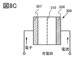
- the flow of current during charging of the secondary battery will be described with reference to FIG. 8C.
- a secondary battery using lithium is regarded as one closed circuit, the movement of lithium ions and the flow of current are in the same direction.
- the anode (anode) and the cathode (cathode) are exchanged by charging and discharging, and the oxidation reaction and the reduction reaction are exchanged. Therefore, an electrode having a high reaction potential is called a positive electrode.
- An electrode having a low reaction potential is called a negative electrode. Therefore, in the present specification, the positive electrode is "positive electrode” or “positive electrode” regardless of whether the battery is being charged, discharged, a reverse pulse current is applied, or a charging current is applied.
- a charger is connected to the two terminals shown in FIG. 8C, and the secondary battery 300 is charged. As the charging of the secondary battery 300 progresses, the potential difference between the electrodes increases.
- a plurality of secondary batteries 600 may be sandwiched between the conductive plate 613 and the conductive plate 614 to form the module 615.
- the plurality of secondary batteries 600 may be connected in parallel, may be connected in series, or may be connected in parallel and then further connected in series.
- FIG. 10A and 10B are views showing an external view of the secondary battery.
- the secondary battery 913 is connected to the antenna 914 and the antenna 915 via the circuit board 900.
- a label 910 is affixed to the secondary battery 913. Further, as shown in FIG. 10B, the secondary battery 913 is connected to the terminal 951 and the terminal 952.
- the circuit board 900 has a terminal 911 and a circuit 912.
- Terminal 911 is connected to terminal 951, terminal 952, antenna 914, antenna 915, and circuit 912.
- a plurality of terminals 911 may be provided, and each of the plurality of terminals 911 may be used as a control signal input terminal, a power supply terminal, or the like.
- the antenna 914 is provided on one side of the pair of surfaces of the secondary battery 913 with the layer 916 interposed therebetween, and as shown in FIG. 11B, the layer 917 is provided on the other side of the pair of surfaces of the secondary battery 913.
- An antenna 918 is provided on the sandwich.
- the layer 917 has a function capable of shielding the electromagnetic field generated by the secondary battery 913, for example.
- a magnetic material can be used as the layer 917.
- the antenna 918 has, for example, a function capable of performing data communication with an external device.
- an antenna having a shape applicable to the antenna 914 can be applied.
- a communication method between the secondary battery and other devices via the antenna 918 a response method that can be used between the secondary battery and other devices such as NFC (Near Field Communication) shall be applied. Can be done.
- the display device 920 may be provided in the secondary battery 913 shown in FIGS. 10A and 10B.
- the display device 920 is electrically connected to the terminal 911. It is not necessary to provide the label 910 on the portion where the display device 920 is provided.
- the description of the secondary battery shown in FIGS. 10A and 10B can be appropriately incorporated.
- the display device 920 may display, for example, an image showing whether or not charging is in progress, an image showing the amount of stored electricity, and the like.
- an electronic paper for example, a liquid crystal display device, an electroluminescence (also referred to as EL) display device, or the like can be used.
- the power consumption of the display device 920 can be reduced by using electronic paper.
- the sensor 921 includes, for example, displacement, position, velocity, acceleration, angular velocity, rotation speed, distance, light, liquid, magnetism, temperature, chemical substance, voice, time, hardness, electric field, current, voltage, power, radiation, flow rate. , Humidity, inclination, vibration, odor, or infrared rays may be measured.
- data temperature or the like
- indicating the environment in which the secondary battery is placed can be detected and stored in the memory in the circuit 912.
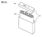
- the housing 930 shown in FIG. 12A may be formed of a plurality of materials.
- the housing 930a and the housing 930b are bonded to each other, and the winding body 950 is provided in the region surrounded by the housing 930a and the housing 930b.
- the wound body 950 has a negative electrode 931, a positive electrode 932, and a separator 933.
- the wound body 950 is a wound body in which the negative electrode 931 and the positive electrode 932 are overlapped and laminated with the separator 933 interposed therebetween, and the laminated sheet is wound.
- a plurality of layers of the negative electrode 931, the positive electrode 932, and the separator 933 may be further laminated.
- the negative electrode 931 is connected to the terminal 911 shown in FIG. 10 via one of the terminal 951 and the terminal 952.
- the positive electrode 932 is connected to the terminal 911 shown in FIG. 10 via the other of the terminal 951 and the terminal 952.
- the laminated type secondary battery 980 will be described with reference to FIG.
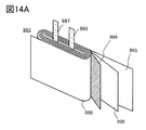
- the laminated secondary battery 980 has a wound body 993 shown in FIG. 14A.
- the wound body 993 has a negative electrode 994, a positive electrode 995, and a separator 996. Similar to the winding body 950 described with reference to FIG. 13, the wound body 993 is formed by laminating a negative electrode 994 and a positive electrode 995 on top of each other with a separator 996 interposed therebetween, and winding the laminated sheet.
- FIG. 14 an example of a secondary battery 980 having a wound body in a space formed by a film serving as an exterior body has been described.
- a secondary battery 980 having a wound body in a space formed by a film serving as an exterior body
- It may be a secondary battery having a plurality of strip-shaped positive electrodes, separators and negative electrodes.
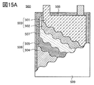
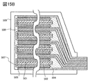
- the laminated type secondary battery 500 shown in FIG. 15A includes a positive electrode 503 having a positive electrode current collector 501 and a positive electrode active material layer 502, a negative electrode 506 having a negative electrode current collector 504 and a negative electrode active material layer 505, and a separator 507. , The electrolytic solution 508, and the exterior body 509. A separator 507 is installed between the positive electrode 503 and the negative electrode 506 provided in the exterior body 509. Further, the inside of the exterior body 509 is filled with the electrolytic solution 508. As the electrolytic solution 508, the electrolytic solution shown in the second embodiment can be used.
- the exterior body 509 has a highly flexible metal such as aluminum, stainless steel, copper, and nickel on a film made of a material such as polyethylene, polypropylene, polycarbonate, ionomer, and polyamide.
- a three-layer structure laminate film in which a thin film is provided and an insulating synthetic resin film such as a polyamide resin or a polyester resin is provided on the metal thin film as the outer surface of the exterior body can be used.
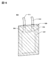
- FIGS. 16 and 17 have a positive electrode 503, a negative electrode 506, a separator 507, an exterior body 509, a positive electrode lead electrode 510, and a negative electrode lead electrode 511.
- the negative electrode 506, the separator 507, and the positive electrode 503 are arranged on the exterior body 509.
- FIG. 19A is a perspective view showing a state in which three laminated type secondary batteries 500 are sandwiched and fixed between the first plate 521 and the second plate 524.
- the three secondary batteries 500 can be pressurized by fixing the distance between the first plate 521 and the second plate 524 using the fixing device 525a and the fixing device 525b. it can.
- FIG. 20 is an example of a cell for evaluating the material of an all-solid-state battery.
- FIG. 20C As an evaluation material, an example of laminating a positive electrode 750a, a solid electrolyte layer 750b, and a negative electrode 750c is shown, and a cross-sectional view is shown in FIG. 20C.
- the same reference numerals are used for the same parts in FIGS. 20A, 20B, and 20C.
- the electrode plate 751 and the lower member 761 electrically connected to the positive electrode 750a correspond to the positive electrode terminals. It can be said that the electrode plate 753 and the upper member 762 that are electrically connected to the negative electrode 750c correspond to the negative electrode terminals.
- the electrical resistance and the like can be measured while pressing the evaluation material through the electrode plate 751 and the electrode plate 753.
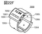
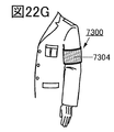
- the display unit 7202 of the portable information terminal 7200 has a secondary battery of one aspect of the present invention.
- a lightweight and long-life portable information terminal can be provided.
- the secondary battery 7104 shown in FIG. 22E can be incorporated in a curved state inside the housing 7201 or in a bendable state inside the band 7203.
- FIG. 22H is a perspective view of a device also called a cigarette-containing smoking device (electronic cigarette).
- the electronic cigarette 7500 is composed of an atomizer 7501 including a heating element, a secondary battery 7504 for supplying electric power to the atomizer, and a cartridge 7502 including a liquid supply bottle and a sensor.
- a protection circuit for preventing overcharging or overdischarging of the secondary battery 7504 may be electrically connected to the secondary battery 7504.
- the secondary battery 7504 shown in FIG. 22H has an external terminal so that it can be connected to a charging device. Since the secondary battery 7504 becomes the tip portion when it is held, it is desirable that the total length is short and the weight is light. Since the secondary battery of one aspect of the present invention has a high capacity and good cycle characteristics, it is possible to provide a compact and lightweight electronic cigarette 7500 that can be used for a long period of time.
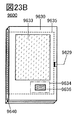
- FIG. 23C shows the solar cell 9633, the storage body 9635, the DCDC converter 9636, the converter 9637, the switches SW1 to SW3, and the display unit 9631. This is the location corresponding to the charge / discharge control circuit 9634 shown in FIG. 23B.
- high-frequency heating devices such as microwave ovens and electronic devices such as electric rice cookers require high electric power in a short time. Therefore, by using the secondary battery according to one aspect of the present invention as an auxiliary power source for assisting the electric power that cannot be covered by the commercial power source, it is possible to prevent the breaker of the commercial power source from tripping when the electronic device is used. ..
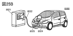
- the power receiving device on the vehicle and supply electric power from the ground power transmission device in a non-contact manner to charge the vehicle.
- this non-contact power supply system by incorporating a power transmission device on the road or the outer wall, it is possible to charge the battery not only while the vehicle is stopped but also while the vehicle is running.
- the non-contact power feeding method may be used to transmit and receive electric power between vehicles.
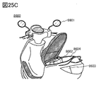
- a solar cell may be provided on the exterior portion of the vehicle to charge the secondary battery when the vehicle is stopped or running.
- An electromagnetic induction method or a magnetic field resonance method can be used to supply power in such a non-contact manner.
- This embodiment can be implemented in combination with other embodiments as appropriate.
- a positive electrode active material having a small particle size was prepared by the method for producing the positive electrode active material 100 shown in the first embodiment and FIG.
- nickel hydroxide was prepared as a nickel source (step S21).
- Aluminum hydroxide was prepared as an aluminum source (step S22).
- step S41 the lithium cobalt oxide, nickel hydroxide, aluminum hydroxide and the mixture 902 prepared above were mixed with a ball mill (step S41) to obtain a mixture 903 (step S42).
- the mixing ratio was set so that the number of atoms of nickel was 0.5, the number of atoms of aluminum was 0.5, and the number of atoms of magnesium was 1 when the number of atoms of cobalt was 100.
- a positive electrode active material having a large particle size was prepared by the method for producing the positive electrode active material 200 shown in the first embodiment and FIG.
- lithium cobalt oxide, nickel hydroxide, aluminum hydroxide and the mixture 902 were mixed with a ball mill (step S41) to obtain a mixture 903 (step S42).
- the mixing ratio was set so that the number of atoms of nickel was 0.5, the number of atoms of aluminum was 0.5, and the number of atoms of magnesium was 1 when the number of atoms of cobalt was 100.
- Sample 300 was prepared by crushing lithium cobalt oxide particles (trade name: CellSeed C-5H) manufactured by Nippon Chemical Industrial Co., Ltd. at 200 rpm for 12 hours using a ball mill.
- Celseed C-5H has a magnesium concentration and fluorine concentration of 50 ppm wt or less, a calcium concentration, an aluminum concentration and a silicon concentration of 100 ppm wt or less, and a nickel concentration of 150 ppm wt or less in impurity analysis by glow discharge mass spectrometry (GD-MS).
- Table 1 shows the preparation conditions for Sample 99, Sample 100, Sample 101, Sample 200, and Sample 300.
- the sample 100 and the sample 101 having a relatively small particle size and the sample 200 having a relatively large particle size could be prepared by the method shown in the first embodiment. It has been clarified that as a method for crushing the sample 99, it is more preferable to use a thin film swirling high-speed mixer than a ball mill because the particles do not become too fine.
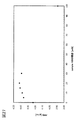
- FIG. 27 shows the relationship between the mixing ratio and PPD as a graph.
- the PPD could be made larger than when the sample was not mixed. From sample 5:95 to sample 30:70, the PPD gave good results of 4.3 g / cc or more, and the PPD of sample 20:80 was the best.
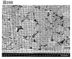
- the positive electrode for cross-sectional SEM observation was prepared as follows.
- sample 100 ′′ prepared in the same manner as in Example 1 and sample 200 prepared in the same manner as in Example 1 were used except that the annealing conditions were set to 850 ° C. and 10 hours.
- Carbon black TIMCAL SUPER C65, Imerys
- PVDF Solef 5130, SOLVEY
- An aluminum foil having a thickness of 20 ⁇ m was used as the current collector.
- NMP was used as the solvent.
- a slurry was prepared by the method for producing a positive electrode described in the second embodiment, applied to a current collector, dried, and pressurized. Pressurization was performed at 210 kN / m and then at 1467 kN / m.
- the amount of the positive electrode active material layer supported on the current collector was about 10 mg / cm 2 .
- FIG. 28A which is a mixture of the positive electrode active material 100 ′′ having a small particle size and the positive electrode active material 200 having a large particle size, there were few voids in which the particles of the positive electrode active material did not exist.
- FIG. 28B prepared only with the positive electrode active material 200 having a large particle size, many voids were observed.
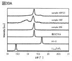
- FIG. 29 shows the XRD pattern of the positive electrode using the sample 100', the sample 100'(2), and the sample 200. Patterns of pseudo-spinel, H1-3 and Li 0.35 CoO 2 are also shown side by side for comparison. Further, FIG. 30A shows a pattern in which the region where 2 ⁇ is 18 or more and 21 or less is enlarged in FIG. 29, and FIG. 30B shows a pattern in which the region where 2 ⁇ is 43 or more and 46 or less is enlarged.
- a diffraction peak of .10 ° was observed, demonstrating that it has a pseudo-spinel-type crystal structure.
- none of the samples showed the characteristics of the H1-3 type crystal structure.
- the conductive auxiliary agent, the binder, the mixing ratio of the conductive auxiliary agent, the binder and the positive electrode active material, the coating on the current collector and the pressurization were prepared in the same manner as the positive electrode for cross-section SEM observation.
- polypropylene (Celgard 2400, Celgard) having a thickness of 25 ⁇ m and a porosity of 41% was used.
- Lithium metal was used for the negative electrode.
- a coin cell CR2032 type, diameter 20 mm, height 3.2 mm
- stainless steel (SUS) was used for the exterior body.
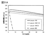
- Sample 100'(2) The cycle characteristics of all the positive electrode active materials were good.
Landscapes
- Chemical & Material Sciences (AREA)
- Organic Chemistry (AREA)
- Inorganic Chemistry (AREA)
- Engineering & Computer Science (AREA)
- Chemical Kinetics & Catalysis (AREA)
- Electrochemistry (AREA)
- General Chemical & Material Sciences (AREA)
- Materials Engineering (AREA)
- Geology (AREA)
- Life Sciences & Earth Sciences (AREA)
- Manufacturing & Machinery (AREA)
- General Life Sciences & Earth Sciences (AREA)
- Battery Electrode And Active Subsutance (AREA)
Abstract
Description
図2は正極活物質の充電深度と結晶構造を説明する図である。
図3は結晶構造から計算されるXRDパターンである。
図4は正極活物質の作製方法の例を説明する図である。
図5は正極活物質の作製方法の例を説明する図である。
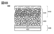
図6Aおよび図6Bは二次電池の例を説明する図である。
図7は二次電池の例を説明する図である。
図8Aおよび図8Bはコイン型二次電池を説明する図である。図8Cは二次電池の電流の流れを説明する図である。
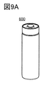
図9Aおよび図9Bは円筒型二次電池を説明する図である。図9Cおよび図9Dは複数の円筒形二次電池を有するモジュールを説明する図である。
図10Aおよび図10Bは二次電池の例を説明する図である。
図11A乃至図11Dは二次電池の例を説明する図である。
図12Aおよび図12Bは二次電池の例を説明する図である。
図13は二次電池の例を説明する図である。
図14A乃至図14Cはラミネート型の二次電池を説明する図である。
図15Aおよび図15Bはラミネート型の二次電池を説明する図である。
図16は二次電池の外観を示す図である。
図17は二次電池の外観を示す図である。
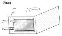
図18A乃至図18Cは二次電池の作製方法を説明する図である。
図19Aおよび図19Bは二次電池およびその作製方法の例を説明する図である。
図20A乃至図20Cは二次電池の例を説明する図である。
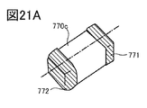
図21Aおよび図21Bは二次電池の例を説明する図である。
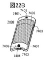
図22A乃至図22Hは電子機器の例を説明する図である。
図23A乃至図23Cは電子機器の例を説明する図である。
図24は電子機器の例を説明する図である。
図25A乃至図25Cは車両の例を説明する図である。
図26は正極活物質の粒度分布を示すグラフである。
図27は正極活物質の粉体パッキング密度を示すグラフである。
図28Aおよび図28Bは正極の断面SEM像である。
図29は正極のXRDパターンである。
図30Aおよび図30Bは正極のXRDパターンである。
図31Aおよび図31Bは二次電池のサイクル特性を示すグラフである。
図32Aおよび図32Bは二次電池のサイクル特性を示すグラフである。
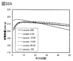
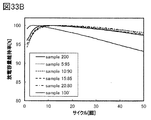
図33Aおよび図33Bは二次電池のサイクル特性を示すグラフである。
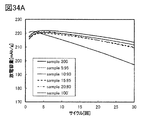
図34Aおよび図34Bは二次電池のサイクル特性を示すグラフである。
本実施の形態では、図1乃至図5を用いて、本発明の一態様の正極活物質、正極活物質を有する正極、および正極活物質の作製方法について説明する。
本発明の一態様の正極活物質100は、リチウム、コバルト、ニッケル、アルミニウム、マグネシウム、酸素およびフッ素を有する複合酸化物の粒子群である。
また上述の比較的小粒径の正極活物質100と、より粒径の大きい正極活物質200を混合した粒子の集合体を二次電池に用いると、体積当たりの容量を向上させることができ好ましい。
正極活物質100と正極活物質200の混合比は、粉体パッキング密度(以下PPD)が大きくなるような混合比とすると、二次電池の体積あたりの容量を向上させることができ好ましい。

また、正極活物質100および正極活物質200は、高電圧で充電したときに擬スピネル型の結晶構造を有することが好ましい。以下に擬スピネル型の結晶構造について説明する。
ある複合酸化物が、高電圧で充電したとき擬スピネル型結晶構造を有するか否かは、例えば対極にリチウムを用いたコインセル(CR2032タイプ、直径20mm高さ3.2mm)を作製して充電し、XRDで結晶構造を推定することで判断することができる。
0112]
より具体的には、正極には、正極活物質、導電助剤およびバインダを混合したスラリーを、アルミニウム箔の正極集電体に塗工したものを用いることができる。このとき正極活物質層が薄すぎると、XRDでアルミニウム箔のシグナルが検出されるので、正極活物質層はある程度の厚さがあることが好ましい。また、塗工後にプレスしていない正極を用いると、2θ=18°から20°付近の(003)面由来のピーク以外も確認しやすいため、好ましい。
擬スピネル型の結晶構造と、H1−3型結晶構造のモデルから計算される、CuKα1線による理想的な粉末XRDパターンを図3に示す。また比較のため充電深度0のLiCoO2(O3)と、充電深度1のCoO2(O1)の結晶構造から計算される理想的なXRDパターンも示す。なお、LiCoO2(O3)およびCoO2(O1)のパターンはICSD(Inorganic Crystal Structure Database)(非特許文献5参照)より入手した結晶構造情報からMaterials Studio(BIOVIA)のモジュールの一つである、Reflex Powder Diffractionを用いて作成した。2θの範囲は15°から75°とし、Step size=0.01、波長λ1=1.540562×10⁻¹⁰m、λ2は設定なし、Monochromatorはsingleとした。H1−3型結晶構造のパターンは非特許文献3に記載の結晶構造情報から同様に作成した。擬スピネル型の結晶構造のパターンは本発明の一態様の正極活物質のXRDパターンから結晶構造を推定し、TOPAS ver.3(Bruker社製結晶構造解析ソフトウェア)を用いてフィッティングし、他と同様にXRDパターンを作成した。
また、本発明の一態様の正極活物質は、高電圧で充電した後、例えば0.2C以下の低いレートで放電すると、放電終了間近に特徴的な電圧の変化が表れることがある。この変化は、放電曲線から求めたdQ/dVvsV曲線において、3.5Vから3.9Vの範囲に、少なくとも1つのピークが存在することで明瞭に確かめることができる。
次に、図4を用いて正極活物質100の作製方法の一例を説明する。正極活物質100は、まずコバルト酸リチウムを合成した後、ニッケル源、アルミニウム源、マグネシウム源およびフッ素源を混合し加熱することで作製することが好ましい。また、加熱後に解砕処理を行うことが好ましい。
まず出発材料として、リチウム源と、コバルト源を用意する。リチウム源としては、例えば炭酸リチウム、フッ化リチウムを用いることができる。コバルト源としては、例えば酸化コバルトを用いることができる。
次に、上記の出発原料を混合する。混合には例えばボールミル、ビーズミル等を用いることができる。ボールミルを用いる場合は、たとえばメディアとしてジルコニアボールを用いることができる。
次に、ステップS12で混合した材料を加熱する。本ステップは焼成、または第1の加熱という場合がある。加熱は800℃以上1100℃未満で行うことが好ましく、900℃以上1000℃以下で行うことがより好ましく、950℃程度がさらに好ましい。温度が低すぎると、出発材料の分解および溶融が不十分となるおそれがある。一方温度が高すぎると、コバルトが還元する、リチウムが蒸散するなどの原因で、コバルトが2価となる欠陥が生じるおそれがある。
ステップS13で加熱した材料を回収し、コバルト酸リチウムを得る。
次に、ニッケル源を用意する。ニッケル源としてはたとえば水酸化ニッケル、フッ化ニッケルを用いることができる。
次に、アルミニウム源を用意する。アルミニウム源としてはたとえば水酸化アルミニウム、フッ化アルミニウム等を用いることができる。
次に、マグネシウム源およびフッ素源を用意する。マグネシウム源としてはたとえばフッ化マグネシウム、水酸化マグネシウム、炭酸マグネシウム等を用いることができる。フッ素源としてはたとえばフッ化リチウム、フッ化マグネシウム等を用いることができる。つまり、フッ化リチウムはリチウム源としてもフッ素源としても用いることができ、フッ化マグネシウムはフッ素源としてもマグネシウム源としても用いることができる。
次に、マグネシウム源およびフッ素源を解砕および混合する。混合は乾式または湿式で行うことができるが、湿式はより小さく粉砕することができるため好ましい。混合には例えばボールミル、ビーズミル等を用いることができる。ボールミルを用いる場合は、例えばメディアとしてジルコニアボールを用いることが好ましい。この解砕および混合工程を十分に行い、マグネシウム源およびフッ素源の混合物902を微粉化することが好ましい。
ステップS32で解砕および混合した材料を回収し、混合物902を得る。
次に、コバルト酸リチウム、ニッケル源、アルミニウム源および混合物902を混合する。コバルト酸リチウムが有するコバルトの原子数を100としたとき、混合物902が有するマグネシウムの原子数の相対値が0.1以上6以下なるよう混合することが好ましく、0.3以上3以下となるように混合することがさらに好ましい。
上記で混合した材料を回収し、混合物903を得る。
次に、混合物903を加熱する。本工程は、先の加熱工程(ステップS13)との区別のために、アニールまたは第2の加熱という場合がある。
ステップS43で加熱した材料を回収し、リチウム、コバルト、ニッケル、アルミニウム、マグネシウム、酸素およびフッ素を有する複合酸化物を得る。
アニールが終わった複合酸化物は、一次粒子が凝集して二次粒子になっている場合があるため、ここで解砕処理をする。解砕にはたとえばボールミル、薄膜旋回型高速ミキサ等を用いることができる。解砕にボールミルを用いる場合、たとえば公転半径75mm、自転容器半径20mmのボールミル装置を用い80rpm以上150rpm以下で2時間解砕および混合することが好ましい。解砕に薄膜旋回型高速ミキサを用いると、一次粒子をさらに粉砕しにくくなり好ましい。このようにアニール後に解砕工程を有することで粒径を小さくすることができる。
ステップS45で解砕した材料を回収し、正極活物質100を得る。
次に、図5を用いて正極活物質200の作製方法の一例を説明する。正極活物質200は、コバルト酸リチウムに、ニッケル源、アルミニウム源、マグネシウム源およびフッ素源を混合し加熱することで作製することができる。
図4で説明した正極活物質100の作製方法と同様に、リチウム源およびコバルト源を混合し焼成してコバルト酸リチウムを作製する。ステップS12では、出発原料の粒径が焼成後のコバルト酸リチウムの粒径に影響するため、本ステップでは、ボールミルを用いる場合たとえば公転半径75mm、自転容器半径20mmのボールミル装置を用い80rpm以上300rpm以下で2時間程度解砕および混合することが好ましい。
図4と同様に、ニッケル源およびアルミニウム源を用意する。
図4と同様に、マグネシウム源とフッ素を解砕および混合し、混合物902を得る。
図4と同様に、コバルト酸リチウム、ニッケル源、アルミニウム源および混合物902を混合して混合物903を得る。
次に、混合物903を加熱する。正極活物質200は、正極活物質100よりも粒径が大きいため、適切なアニール温度および時間は正極活物質100と異なる。
ステップS43でアニールした材料を回収し、正極活物質200を得る。
本実施の形態では、先の実施の形態で説明した正極活物質を有する二次電池に用いることのできる材料の例および構成の例について説明する。また、構成の一部について作製方法を説明する。
以下に、正極、負極および電解液が、外装体に包まれている二次電池を例にとって説明する。
正極は、正極活物質層および正極集電体を有する。
正極活物質層は、少なくとも正極活物質を有する。また、正極活物質層は、正極活物質に加えて、活物質表面の被膜、導電助剤またはバインダなどの他の物質を含んでもよい。
正極集電体としては、ステンレス、金、白金、アルミニウム、チタン等の金属、及びこれらの合金など、導電性が高い材料をもちいることができる。また正極集電体に用いる材料は、正極の電位で溶出しないことが好ましい。また、シリコン、チタン、ネオジム、スカンジウム、モリブデンなどの耐熱性を向上させる元素が添加されたアルミニウム合金を用いることができる。また、シリコンと反応してシリサイドを形成する金属元素で形成してもよい。シリコンと反応してシリサイドを形成する金属元素としては、ジルコニウム、チタン、ハフニウム、バナジウム、ニオブ、タンタル、クロム、モリブデン、タングステン、コバルト、ニッケル等がある。集電体は、箔状、板状(シート状)、網状、パンチングメタル状、エキスパンドメタル状等の形状を適宜用いることができる。集電体は、厚みが5μm以上30μm以下のものを用いるとよい。
本発明の一態様の正極活物質100、または正極活物質100と正極活物質200を混合したもの有する正極の作製方法の例として、正極活物質を含むスラリーを作製し、該スラリーを正極集電体に塗工する方法がある。以下にスラリーの作製方法および塗工方法の一例を述べる。
負極は、負極活物質層および負極集電体を有する。また、負極活物質層は、導電助剤およびバインダを有していてもよい。
負極活物質としては、例えば合金系材料や炭素系材料等を用いることができる。
負極集電体には、銅などに加えて、正極集電体と同様の材料を用いることができる。なお負極集電体は、リチウム等のキャリアイオンと合金化しない材料を用いることが好ましい。
電解液は、溶媒と電解質を有する。電解液の溶媒としては、非プロトン性有機溶媒が好ましく、例えば、エチレンカーボネート(EC)、プロピレンカーボネート(PC)、ブチレンカーボネート、クロロエチレンカーボネート、ビニレンカーボネート、γ−ブチロラクトン、γ−バレロラクトン、ジメチルカーボネート(DMC)、ジエチルカーボネート(DEC)、エチルメチルカーボネート(EMC)、ギ酸メチル、酢酸メチル、酢酸エチル、プロピオン酸メチル、プロピオン酸エチル、プロピオン酸プロピル、酪酸メチル、1,3−ジオキサン、1,4−ジオキサン、ジメトキシエタン(DME)、ジメチルスルホキシド、ジエチルエーテル、メチルジグライム、アセトニトリル、ベンゾニトリル、テトラヒドロフラン、スルホラン、スルトン等の1種、又はこれらのうちの2種以上を任意の組み合わせおよび比率で用いることができる。
また二次電池は、セパレータを有することが好ましい。セパレータとしては、例えば、紙、不織布、ガラス繊維、セラミックス、或いはナイロン(ポリアミド)、ビニロン(ポリビニルアルコール系繊維)、ポリエステル、アクリル、ポリオレフィン、ポリウレタンを用いた合成繊維等で形成されたものを用いることができる。セパレータはエンベロープ状に加工し、正極または負極のいずれか一方を包むように配置することが好ましい。
二次電池が有する外装体としては、例えばアルミニウムなどの金属材料や樹脂材料を用いることができる。また、フィルム状の外装体を用いることもできる。フィルムとしては、例えばポリエチレン、ポリプロピレン、ポリカーボネート、アイオノマー、ポリアミド等の材料からなる膜上に、アルミニウム、ステンレス、銅、ニッケル等の可撓性に優れた金属薄膜を設け、さらに該金属薄膜上に外装体の外面としてポリアミド系樹脂、ポリエステル系樹脂等の絶縁性合成樹脂膜を設けた三層構造のフィルムを用いることができる。
以下に、二次電池の構成の一例として、固体電解質を用いた二次電池の構成について説明する。
本実施の形態では、先の実施の形態で説明した正極活物質100または正極活物質100と正極活物質200の混合物を有する二次電池の形状の例について説明する。本実施の形態で説明する二次電池に用いる材料は、先の実施の形態の記載を参酌することができる。
まずコイン型の二次電池の一例について説明する。図8Aはコイン型(単層偏平型)の二次電池の外観図であり、図8Bは、その断面図である。
次に円筒型の二次電池の例について図9を参照して説明する。円筒型の二次電池600の外観図を図9Aに示す。図9Bは、円筒型の二次電池600の断面を模式的に示した図である。図9Bに示すように、円筒型の二次電池600は、上面に正極キャップ(電池蓋)601を有し、側面および底面に電池缶(外装缶)602を有している。これら正極キャップと電池缶(外装缶)602とは、ガスケット(絶縁パッキン)610によって絶縁されている。
二次電池の別の構造例について、図10乃至図13を用いて説明する。
次に、ラミネート型の二次電池の例について、図14乃至図19を参照して説明する。ラミネート型の二次電池は、可撓性を有する構成とすれば、可撓性を有する部位を少なくとも一部有する電子機器に実装すれば、電子機器の変形に合わせて二次電池も曲げることもできる。
ここで、図16に外観図を示すラミネート型二次電池の作製方法の一例について、図18B、図18Cを用いて説明する。
固体電解質を有する二次電池の外装体には、様々な材料および形状のものを用いることができるが、正極、固体電解質層および負極を加圧する機能を有することが好ましい。
本実施の形態では、本発明の一態様である二次電池を電子機器に実装する例について説明する。
本実施の形態では、車両に本発明の一態様である二次電池を搭載する例を示す。

表1に示したサンプルについて、レーザ回折・散乱法により粒度分布を測定した。粒度分布を図26に示す。また、D50、D10、D90、平均値と標準偏差(SD)を表2に示す。

次に小粒径のサンプル100と大粒径のサンプル200を混合したサンプルを作製し、PPDを測定した。サンプル100とサンプル200の混合比とPPDを表3に示す。図27に混合比とPPDの関係をグラフにして示す。

断面SEM観察用の正極は以下のように作製した。正極活物質にはアニール条件を850℃、10時間とした他は実施例1と同様に作製したサンプル100´´と、実施例1と同様に作製したサンプル200を用いた。導電助剤としてカーボンブラック(TIMCAL SUPER C65、Imerys社)、バインダとしてPVDF(Solef 5130,SOLVEY社)を用いた。集電体には厚さ20μmのアルミニウム箔を用いた。溶媒にはNMPを用いた。
XRD用の正極は以下のように作製した。正極活物質には、アニール条件を800℃10時間とした他は実施例1と同様に作製したサンプル100´と、ニッケル、アルミニウム、マグネシウムおよびフッ素の混合量を変更した他はサンプル100´と同様に作製したサンプル100´(2)と、実施例1と同様に作製したサンプル200を用いた。

小粒径の正極活物質100´について、ニッケル、アルミニウム、マグネシウムおよびフッ素の量を変えたものを作製し、二次電池に用いてサイクル特性を評価した。サイクル特性評価用のセルは以下のように作製した。

次に小粒径の正極活物質100´と、より粒径の大きい正極活物質200を混合した粒子の集合体を二次電池に用いてサイクル特性を評価した。
Claims (6)
- 粒子の集合体を有する正極活物質であって、
前記粒子の集合体は、第1の粒子群と、第2の粒子群と、を有し、
前記粒子の集合体は、
リチウム、コバルト、ニッケル、アルミニウム、マグネシウム、酸素およびフッ素を有し、
前記粒子の集合体が有するコバルトの原子数を100としたとき、
ニッケルの原子数は0.05以上2以下、
アルミニウムの原子数は0.05以上2以下、
マグネシウムの原子数は0.1以上6以下であり、
前記粒子の集合体をレーザ回折・散乱法により粒度分布測定したとき、
前記第1の粒子群は第1のピークを有し、前記第2の粒子群は第2のピークを有し、
前記第1のピークは2μm以上4μm以下に極大値を有し、
前記第2のピークは9μm以上25μm以下に極大値を有する、正極活物質。 - 請求項1において、
前記正極活物質の粉体パッキング密度が4.30g/cc以上4.60g/cc以下である、正極活物質。 - 請求項1および請求項2において、
前記粒子の集合体を正極に用い、金属リチウムを負極に用いたリチウムイオン二次電池を、25℃環境下において電池電圧が4.6Vとなるまで定電流充電し、その後電流値が0.02Cとなるまで定電圧充電した後、前記正極をCuKα1線による粉末X線回折で分析したとき、
2θ=19.30±0.20°、および2θ=45.55±0.10°に回折ピークを有する、正極活物質。 - リチウム、コバルト、ニッケル、アルミニウム、マグネシウム、酸素およびフッ素を有する粒子群を有する正極活物質であって、
前記粒子群が有するコバルトの原子数を100としたとき、
ニッケルの原子数は0.05以上2以下、
アルミニウムの原子数は0.05以上2以下、
マグネシウムの原子数は0.1以上6以下であり、
レーザ回折・散乱法により粒度分布を測定したとき、2μm以上4μm以下に極大値を有し、
前記粒子群を正極に用い、金属リチウムを負極に用いたリチウムイオン二次電池を、25℃環境下において電池電圧が4.6Vとなるまで定電流充電し、その後電流値が0.02Cとなるまで定電圧充電した後、前記正極をCuKα1線による粉末X線回折で分析したとき、
2θ=19.30±0.20°、および2θ=45.55±0.10°に回折ピークを有する、正極活物質。 - リチウム、コバルト、ニッケル、アルミニウム、マグネシウム、酸素およびフッ素を有し、レーザ回折・散乱法により粒度分布を測定したときのD50が2μm以上4μm以下である第1の粒子群を作製する第1の工程と、
リチウム、コバルト、ニッケル、アルミニウム、マグネシウム、酸素およびフッ素を有し、レーザ回折・散乱法により粒度分布を測定したときのD50が16μm以上22μm以下である第2の粒子群を作製する第2の工程と、
前記第1の粒子群と前記第2の粒子群を混合し粒子の集合体を作製する第3の工程と、を有し、
前記粒子の集合体に占める前記第1の粒子群の割合は5重量%以上20重量%以下である、正極活物質の作製方法。 - 請求項5において、前記第1の工程は、
薄膜旋回型ミキサで解砕する工程を有する正極活物質の作製方法。
Priority Applications (5)
| Application Number | Priority Date | Filing Date | Title |
|---|---|---|---|
| US17/621,792 US20220371906A1 (en) | 2019-06-28 | 2020-06-16 | Positive electrode active material, positive electrode, secondary battery, and manufacturing method thereof |
| CN202080047718.XA CN114270566A (zh) | 2019-06-28 | 2020-06-16 | 正极活性物质、正极、二次电池以及其制造方法 |
| KR1020227001962A KR20220027974A (ko) | 2019-06-28 | 2020-06-16 | 양극 활물질, 양극, 이차 전지, 및 이들의 제작 방법 |
| JP2021528035A JPWO2020261040A1 (ja) | 2019-06-28 | 2020-06-16 | |
| JP2025280371A JP2026034789A (ja) | 2019-06-28 | 2025-12-24 | 正極活物質、および正極活物質の作製方法 |
Applications Claiming Priority (2)
| Application Number | Priority Date | Filing Date | Title |
|---|---|---|---|
| JP2019-121182 | 2019-06-28 | ||
| JP2019121182 | 2019-06-28 |
Publications (1)
| Publication Number | Publication Date |
|---|---|
| WO2020261040A1 true WO2020261040A1 (ja) | 2020-12-30 |
Family
ID=74059661
Family Applications (1)
| Application Number | Title | Priority Date | Filing Date |
|---|---|---|---|
| PCT/IB2020/055594 Ceased WO2020261040A1 (ja) | 2019-06-28 | 2020-06-16 | 正極活物質、正極、二次電池、およびこれらの作製方法 |
Country Status (5)
| Country | Link |
|---|---|
| US (1) | US20220371906A1 (ja) |
| JP (2) | JPWO2020261040A1 (ja) |
| KR (1) | KR20220027974A (ja) |
| CN (1) | CN114270566A (ja) |
| WO (1) | WO2020261040A1 (ja) |
Cited By (2)
| Publication number | Priority date | Publication date | Assignee | Title |
|---|---|---|---|---|
| WO2024081264A1 (en) * | 2022-10-11 | 2024-04-18 | Entegris, Inc. | Compounds and methods for preparation of aluminates |
| WO2025148081A1 (zh) * | 2024-01-12 | 2025-07-17 | 松山湖材料实验室 | 一种高镍正极材料、二次电池及用电装置 |
Families Citing this family (2)
| Publication number | Priority date | Publication date | Assignee | Title |
|---|---|---|---|---|
| WO2021251234A1 (ja) * | 2020-06-12 | 2021-12-16 | 株式会社Adeka | 電極及びリチウムイオン二次電池 |
| CN116799299B (zh) * | 2023-07-07 | 2025-07-08 | 中国科学院兰州化学物理研究所 | 一种高室温离子电导率的黏土矿物纳米复合材料/聚合物复合固态电解质的制备方法 |
Citations (5)
| Publication number | Priority date | Publication date | Assignee | Title |
|---|---|---|---|---|
| JP2000082466A (ja) * | 1998-07-02 | 2000-03-21 | Nippon Chem Ind Co Ltd | 正極活物質及び非水電解質二次電池 |
| JP2006310311A (ja) * | 2005-04-28 | 2006-11-09 | Samsung Sdi Co Ltd | リチウム二次電池用陽極及びこれを含むリチウム二次電池 |
| JP2008010234A (ja) * | 2006-06-28 | 2008-01-17 | Sony Corp | 正極活物質および非水電解質電池 |
| JP2009212021A (ja) * | 2008-03-06 | 2009-09-17 | Hitachi Maxell Ltd | 電気化学素子用電極、非水二次電池および電池システム |
| JP2018195581A (ja) * | 2017-05-19 | 2018-12-06 | 株式会社半導体エネルギー研究所 | 正極活物質、正極活物質の作製方法、および二次電池 |
Family Cites Families (9)
| Publication number | Priority date | Publication date | Assignee | Title |
|---|---|---|---|---|
| KR20060091486A (ko) * | 2005-02-15 | 2006-08-21 | 삼성에스디아이 주식회사 | 양극 활물질, 그 제조 방법 및 이를 채용한 양극과 리튬 전지 |
| JP5521266B2 (ja) | 2006-11-21 | 2014-06-11 | 住友化学株式会社 | 正極活物質用粉末および正極活物質 |
| JP4316656B1 (ja) * | 2008-07-25 | 2009-08-19 | 三井金属鉱業株式会社 | 層構造を有するリチウム遷移金属酸化物 |
| KR101653334B1 (ko) * | 2009-09-09 | 2016-09-01 | 소니 주식회사 | 정극 활물질, 정극, 비수 전해질 전지 및 정극 활물질의 제조 방법 |
| US10326166B2 (en) * | 2016-08-15 | 2019-06-18 | GM Global Technology Operations LLC | Gel electrolytes and precursors thereof |
| JP7163010B2 (ja) | 2017-07-14 | 2022-10-31 | 株式会社半導体エネルギー研究所 | 正極活物質、正極、および二次電池 |
| JP2019029110A (ja) * | 2017-07-26 | 2019-02-21 | 旭化成株式会社 | 非水系リチウム型蓄電素子用のリチウム化合物 |
| KR20250051789A (ko) * | 2017-11-24 | 2025-04-17 | 가부시키가이샤 한도오따이 에네루기 켄큐쇼 | 이차 전지 및 이차 전지의 제작 방법 |
| JP7633170B2 (ja) * | 2019-09-20 | 2025-02-19 | 株式会社半導体エネルギー研究所 | 二次電池用正極、二次電池および電子機器 |
-
2020
- 2020-06-16 JP JP2021528035A patent/JPWO2020261040A1/ja not_active Withdrawn
- 2020-06-16 US US17/621,792 patent/US20220371906A1/en active Pending
- 2020-06-16 KR KR1020227001962A patent/KR20220027974A/ko not_active Ceased
- 2020-06-16 WO PCT/IB2020/055594 patent/WO2020261040A1/ja not_active Ceased
- 2020-06-16 CN CN202080047718.XA patent/CN114270566A/zh active Pending
-
2025
- 2025-12-24 JP JP2025280371A patent/JP2026034789A/ja active Pending
Patent Citations (5)
| Publication number | Priority date | Publication date | Assignee | Title |
|---|---|---|---|---|
| JP2000082466A (ja) * | 1998-07-02 | 2000-03-21 | Nippon Chem Ind Co Ltd | 正極活物質及び非水電解質二次電池 |
| JP2006310311A (ja) * | 2005-04-28 | 2006-11-09 | Samsung Sdi Co Ltd | リチウム二次電池用陽極及びこれを含むリチウム二次電池 |
| JP2008010234A (ja) * | 2006-06-28 | 2008-01-17 | Sony Corp | 正極活物質および非水電解質電池 |
| JP2009212021A (ja) * | 2008-03-06 | 2009-09-17 | Hitachi Maxell Ltd | 電気化学素子用電極、非水二次電池および電池システム |
| JP2018195581A (ja) * | 2017-05-19 | 2018-12-06 | 株式会社半導体エネルギー研究所 | 正極活物質、正極活物質の作製方法、および二次電池 |
Cited By (2)
| Publication number | Priority date | Publication date | Assignee | Title |
|---|---|---|---|---|
| WO2024081264A1 (en) * | 2022-10-11 | 2024-04-18 | Entegris, Inc. | Compounds and methods for preparation of aluminates |
| WO2025148081A1 (zh) * | 2024-01-12 | 2025-07-17 | 松山湖材料实验室 | 一种高镍正极材料、二次电池及用电装置 |
Also Published As
| Publication number | Publication date |
|---|---|
| JP2026034789A (ja) | 2026-02-27 |
| US20220371906A1 (en) | 2022-11-24 |
| KR20220027974A (ko) | 2022-03-08 |
| JPWO2020261040A1 (ja) | 2020-12-30 |
| CN114270566A (zh) | 2022-04-01 |
Similar Documents
| Publication | Publication Date | Title |
|---|---|---|
| JP7655687B2 (ja) | リチウムイオン二次電池 | |
| KR102871222B1 (ko) | 양극 활물질의 제작 방법 | |
| JP2023033572A (ja) | リチウムイオン二次電池の作製方法 | |
| JP2023021178A (ja) | リチウムイオン二次電池 | |
| JP7785866B2 (ja) | 正極活物質 | |
| JP7773593B2 (ja) | 正極活物質 | |
| JP2024036638A (ja) | リチウムイオン二次電池用正極材、リチウムイオン二次電池、電子機器および車両 | |
| JP2026034789A (ja) | 正極活物質、および正極活物質の作製方法 | |
| WO2022038448A1 (ja) | 電極の作製方法、二次電池、電子機器および車両 |
Legal Events
| Date | Code | Title | Description |
|---|---|---|---|
| 121 | Ep: the epo has been informed by wipo that ep was designated in this application |
Ref document number: 20830741 Country of ref document: EP Kind code of ref document: A1 |
|
| ENP | Entry into the national phase |
Ref document number: 2021528035 Country of ref document: JP Kind code of ref document: A |
|
| NENP | Non-entry into the national phase |
Ref country code: DE |
|
| ENP | Entry into the national phase |
Ref document number: 20227001962 Country of ref document: KR Kind code of ref document: A |
|
| 122 | Ep: pct application non-entry in european phase |
Ref document number: 20830741 Country of ref document: EP Kind code of ref document: A1 |