WO2020255802A1 - 非水電解質二次電池用セパレータ及びその製造方法 - Google Patents
非水電解質二次電池用セパレータ及びその製造方法 Download PDFInfo
- Publication number
- WO2020255802A1 WO2020255802A1 PCT/JP2020/022721 JP2020022721W WO2020255802A1 WO 2020255802 A1 WO2020255802 A1 WO 2020255802A1 JP 2020022721 W JP2020022721 W JP 2020022721W WO 2020255802 A1 WO2020255802 A1 WO 2020255802A1
- Authority
- WO
- WIPO (PCT)
- Prior art keywords
- separator
- aqueous electrolyte
- secondary battery
- electrolyte secondary
- based resin
- Prior art date
- Legal status (The legal status is an assumption and is not a legal conclusion. Google has not performed a legal analysis and makes no representation as to the accuracy of the status listed.)
- Ceased
Links
Classifications
-
- H—ELECTRICITY
- H01—ELECTRIC ELEMENTS
- H01M—PROCESSES OR MEANS, e.g. BATTERIES, FOR THE DIRECT CONVERSION OF CHEMICAL ENERGY INTO ELECTRICAL ENERGY
- H01M10/00—Secondary cells; Manufacture thereof
- H01M10/05—Accumulators with non-aqueous electrolyte
- H01M10/052—Li-accumulators
-
- H—ELECTRICITY
- H01—ELECTRIC ELEMENTS
- H01M—PROCESSES OR MEANS, e.g. BATTERIES, FOR THE DIRECT CONVERSION OF CHEMICAL ENERGY INTO ELECTRICAL ENERGY
- H01M10/00—Secondary cells; Manufacture thereof
- H01M10/05—Accumulators with non-aqueous electrolyte
- H01M10/056—Accumulators with non-aqueous electrolyte characterised by the materials used as electrolytes, e.g. mixed inorganic/organic electrolytes
- H01M10/0564—Accumulators with non-aqueous electrolyte characterised by the materials used as electrolytes, e.g. mixed inorganic/organic electrolytes the electrolyte being constituted of organic materials only
- H01M10/0566—Liquid materials
- H01M10/0568—Liquid materials characterised by the solutes
-
- H—ELECTRICITY
- H01—ELECTRIC ELEMENTS
- H01M—PROCESSES OR MEANS, e.g. BATTERIES, FOR THE DIRECT CONVERSION OF CHEMICAL ENERGY INTO ELECTRICAL ENERGY
- H01M10/00—Secondary cells; Manufacture thereof
- H01M10/05—Accumulators with non-aqueous electrolyte
- H01M10/056—Accumulators with non-aqueous electrolyte characterised by the materials used as electrolytes, e.g. mixed inorganic/organic electrolytes
- H01M10/0564—Accumulators with non-aqueous electrolyte characterised by the materials used as electrolytes, e.g. mixed inorganic/organic electrolytes the electrolyte being constituted of organic materials only
- H01M10/0566—Liquid materials
- H01M10/0569—Liquid materials characterised by the solvents
-
- H—ELECTRICITY
- H01—ELECTRIC ELEMENTS
- H01M—PROCESSES OR MEANS, e.g. BATTERIES, FOR THE DIRECT CONVERSION OF CHEMICAL ENERGY INTO ELECTRICAL ENERGY
- H01M4/00—Electrodes
- H01M4/02—Electrodes composed of, or comprising, active material
- H01M4/13—Electrodes for accumulators with non-aqueous electrolyte, e.g. for lithium-accumulators; Processes of manufacture thereof
- H01M4/133—Electrodes based on carbonaceous material, e.g. graphite-intercalation compounds or CFx
-
- H—ELECTRICITY
- H01—ELECTRIC ELEMENTS
- H01M—PROCESSES OR MEANS, e.g. BATTERIES, FOR THE DIRECT CONVERSION OF CHEMICAL ENERGY INTO ELECTRICAL ENERGY
- H01M4/00—Electrodes
- H01M4/02—Electrodes composed of, or comprising, active material
- H01M4/62—Selection of inactive substances as ingredients for active masses, e.g. binders, fillers
Definitions
- the present invention relates to a separator for a non-aqueous electrolyte secondary battery, a method for producing the same, and a non-aqueous electrolyte secondary battery including the separator for the non-aqueous electrolyte secondary battery.
- Non-aqueous electrolyte secondary batteries have been developed with the spread of mobile terminals such as mobile phones, notebook personal computers, pad-type information terminal devices, electric vehicles, hybrid vehicles, and the like.
- Non-aqueous electrolyte secondary batteries such as lithium ion secondary batteries differ in form, capacity, performance, etc. depending on their application, but in general, a positive electrode and a negative electrode are installed via a separator (separation film), and LiPF. 6.
- Lithium salts such as LiBF 4 , LiTFSI [lithium (bistrifluoromethylsulfonylimide)] and LiFSI [lithium (bisfluorosulfonylimide)] are stored in a container together with an electrolytic solution dissolved in an organic liquid such as ethylene carbonate. Has a structure.
- non-aqueous electrolyte secondary batteries having the above structure are more likely to have a risk of temperature rise due to external heat, overcharging, smoke generation due to internal short circuit or external short circuit, ignition, explosion, etc. High safety is required.
- most of the separators that make up a non-aqueous electrolyte secondary battery are made of a porous film (porous film), and when the temperature inside the battery rises, the flow of current and ions is blocked by blocking the holes. It has a so-called shutdown function.
- a porous membrane made of a polyolefin resin is widely used as such a separator.
- a separator has been proposed (Patent Document 1).
- Separators having a coating layer on the surface of a porous base material as in Patent Documents 1 to 3 are manufactured by applying a coating liquid containing resin particles, fillers, etc. of a predetermined size or larger to the porous base material and drying the separator. Therefore, resin particles, fillers, and the like do not penetrate into the pores of the porous substrate, and the liquid permeability of the electrolytic solution can be ensured.
- a separator as in Cited Documents 1 to 3 is used, after the electrolytic solution is injected into the battery at the time of manufacture, until the separator absorbs the electrolytic solution and the internal resistance is stabilized. It was found to be disadvantageous from the viewpoint of productivity because it takes time.
- an object of the present invention is a separator for a non-aqueous electrolyte secondary battery capable of stabilizing the internal resistance in a short time during battery production, a method for producing the same, and a non-aqueous electrolyte secondary battery including the separator for the non-aqueous electrolyte secondary battery. Is to provide.
- the present inventor has a non-aqueous electrolyte having a porous base material and an adhering layer containing a polyvinyl alcohol-based resin on at least one surface of the porous base material.
- the above problems can be solved by adjusting the liquid absorption height of the separator for the next battery separator to 1.2 mm or more, and completed the present invention.
- An ethylene carbonate / ethylmethyl carbonate / dimethyl carbonate having a porous base material and an adhering layer containing a polyvinyl alcohol-based resin on at least one surface of the porous base material and having a volume ratio of 1: 1: 1.
- a separator for a non-aqueous electrolyte secondary battery having a liquid absorption height of 1.2 mm or more when a 1.0 M LiPF 6 solution containing the above as a mixed solvent is absorbed for 1 minute.
- the polyvinyl alcohol-based resin is described in any one of [1] to [4], which is at least one selected from the group consisting of an ethylene-vinyl alcohol-based resin, a polyvinyl alcohol, and a polyvinyl acetal-based resin.
- Separator for non-aqueous electrolyte secondary batteries [6] A method for producing a separator for a non-aqueous electrolyte secondary battery, which has a porous base material and an adhering layer containing a polyvinyl alcohol-based resin on at least one surface of the porous base material.
- a method comprising the step (II) of forming an adhering layer on at least one surface of a substrate.
- a non-aqueous electrolyte secondary battery comprising the separator for a non-aqueous electrolyte secondary battery according to any one of [1] to [5].
- the separator for a non-aqueous electrolyte secondary battery of the present invention can stabilize the internal resistance in a short time during battery manufacturing. Therefore, by using the separator for a non-aqueous electrolyte secondary battery of the present invention, a high-performance non-aqueous electrolyte secondary battery can be produced in a short time.
- the separator for a non-aqueous electrolyte secondary battery of the present invention (hereinafter, may be simply referred to as "separator”) includes a porous base material and an adhering layer containing a polyvinyl alcohol-based resin on at least one surface of the porous base material.
- the separator of the present invention may have an ion transport property that separates a positive electrode and a negative electrode in a non-aqueous electrolyte secondary battery and allows ions to pass between the positive electrode and the negative electrode by passing or holding an electrolytic solution.
- An attachment layer means a layer that is attached, adhered, or coated to at least one surface of a porous substrate.
- the adhering layer contains a polyvinyl alcohol-based resin.
- the polyvinyl alcohol-based resin include polyvinyl alcohol, ethylene-vinyl alcohol-based resin, and polyvinyl acetal-based resin. These polyvinyl alcohol-based resins can be used alone or in combination of two or more.
- Examples of the ethylene-vinyl alcohol-based resin include those obtained by saponifying an ethylene-vinyl ester copolymer such as an ethylene-vinyl acetate copolymer.
- the ethylene content (ethylene modification amount) of the ethylene-vinyl alcohol resin is preferably 20 mol% or more, more preferably 25 mol% or more, still more preferably 30 mol% or more, preferably 60 mol% or less, and more. It is preferably 55 mol% or less, more preferably 50 mol% or less.
- the ethylene content is at least the above lower limit, the water resistance of the separator can be improved, and when the ethylene content is at least the above upper limit, the ethylene-vinyl alcohol resin has appropriate hydrophilicity. Therefore, it becomes easy to process the separator.
- the ethylene-vinyl alcohol resin for forming the separator of the present invention has an ethylene content of 20 to 60 mol% and ken from the viewpoint of affinity with an electrolytic solution. Those having a degree of conversion of 80 mol% or more are preferable.
- the copolymerization form of the ethylene-vinyl alcohol-based resin is not particularly limited, and may be any of a random copolymer, an alternating copolymer, a block copolymer, a graft copolymer and the like.
- ethylene-vinyl alcohol-based resin in the present invention a commercially available product may be used, or a resin prepared by a conventionally known method may be used.
- polyvinyl alcohol examples include those obtained by saponifying vinyl alcohol and, if necessary, a resin obtained by polymerizing another monomer.
- it can be produced by a method of saponifying the resin in a state of being dissolved in a solvent such as alcohol.
- the solvent used in this method include lower alcohols such as methanol and ethanol, and methanol can be preferably used.
- the alcohol used in the saponification reaction may contain a solvent such as acetone, methyl acetate, ethyl acetate, or benzene as long as the amount thereof is, for example, 40% by mass or less.
- an alkali metal hydroxide such as potassium hydroxide or sodium hydroxide
- an alkali catalyst such as sodium methoxide
- an acid catalyst such as mineral acid
- the temperature of the saponification reaction is not particularly limited, but is preferably in the range of 20 to 60 ° C.
- the polyvinyl alcohol obtained by the saponification reaction is washed and then dried.
- the polyvinyl acetal-based resin can be produced, for example, by acetalizing the polyvinyl alcohol with an aldehyde, and the acetalization method is not particularly limited, and examples thereof include a precipitation method and a solid-liquid reaction method.
- the precipitation method for example, water or acetone is used as a solvent, polyvinyl alcohol as a raw material is dissolved in water or acetone, a catalyst such as acid is added to carry out an acetalization reaction, and the produced polyvinyl acetal resin is precipitated. This is a method of neutralizing the acid used as a catalyst to obtain a solid powder.
- the solid-liquid reaction method is a method in which the reaction can be carried out in the same manner as the precipitation method, except that a solvent in which the raw material polyvinyl alcohol is not dissolved is used. Regardless of which method is used, the obtained polyvinyl acetal-based resin powder contains impurities such as unreacted aldehydes and salts generated by neutralization. Therefore, the impurities are soluble in order to remove these impurities.
- a high-purity polyvinyl acetal-based resin can be obtained by extraction or evaporative removal using a different solvent.
- aldehyde used for acetalization examples include aliphatic aldehydes such as formaldehyde, acetaldehyde, propyl aldehyde, n-butyl aldehyde (1-butanol), sec-butyl aldehyde, octyl aldehyde, and dodecyl aldehyde; cyclohexanecarbaldehyde and cyclooctane.
- Alicyclic aldehydes such as carboaldehyde, trimethylcyclohexanecarbaldehyde, cyclopentylaldehyde, dimethylcyclohexanecarbaldehyde, methylcyclohexanecarbaldehyde, methylcyclopentylaldehyde; ⁇ -campolenealdehyde, ferlandral, cyclocitral, trimethyltetrahydrobenzaldehyde, Terpen-based aldehydes such as ⁇ -pyronenaldehyde, myrtenal, dihydromirtenal, and camphenylanaldehyde; aromatic aldehydes such as benzaldehyde, naphthoaldehyde, anthralaldehyde, phenylacetaldehyde, tolualdehyde, dimethylbenzaldehyde, cuminaldehyde, and benzylaldehyde; Un
- aldehydes can be used alone or in combination of two or more.
- aliphatic ketones such as 2-propanone, methyl ethyl ketone, 3-pentanone and 2-hexanone; aliphatic alicyclic ketones such as cyclopentanone and cyclohexanone; aromatics such as acetophenone and benzophenone.
- Group ketones and the like can also be used.
- a known acid can be used as the acid catalyst, and examples thereof include inorganic acids such as sulfuric acid, hydrochloric acid, and nitric acid, and organic acids such as paratoluenesulfonic acid.
- the acid catalyst is usually used in an amount such that the acid concentration in the final system of the acetal reaction is 0.5 to 5.0% by mass, but the acid catalyst is not limited to this concentration.
- a predetermined amount of these acid catalysts may be added at one time, but in the case of the precipitation method, the polyvinyl acetal-based resin having relatively fine particles is added in an appropriate number of times in order to precipitate and precipitate. Is preferable.
- the solid-liquid reaction method it is preferable to add a predetermined amount at the beginning of the reaction from the viewpoint of reaction efficiency.
- polyvinyl alcohol-based resins at least one selected from the group consisting of polyvinyl alcohol, ethylene-vinyl alcohol-based resins and polyvinyl acetal-based resins is preferable from the viewpoint of having high liquid absorption and easily stabilizing internal resistance.
- Polyvinyl alcohol and at least one selected from ethylene-vinyl alcohol-based resins are more preferable, and ethylene-vinyl alcohol-based resins are even more preferable.
- the polyvinyl alcohol-based resin may be a monomer (other monomer) that can be copolymerized with these units in addition to the ethylene unit, acetal unit and vinyl alcohol unit as long as the effect of the present invention is not impaired. ) Derived from the structural unit may be included.
- Other monomers include ⁇ -olefins such as propylene, 1-butene, isobutene, 1-hexene; acrylic acid, methacrylic acid, crotonic acid, phthalic acid, phthalic anhydride, maleic acid, maleic anhydride, etc.
- Unsaturated acids such as itaconic acid and itaconic anhydride and salts thereof or alkyl esters having 1 to 18 carbon atoms; acrylamide, N-alkylacrylamide having 1 to 18 carbon atoms, N, N-dimethylacrylamide, 2-acrylamide propane Sulfonic acids and salts thereof, acrylamides such as acrylamidepropyldimethylamine and acid salts thereof or quaternary salts thereof; methacrylamide, N-alkylmethacrylicamide having 1 to 18 carbon atoms, N, N-dimethylmethacrylate, 2-methacryl Methalamides such as amide propanesulfonic acid and its salts, methacrylamide propyldimethylamine and its acid salts or quaternary salts thereof; N-vinylamides such as N-vinylpyrrolidone, N-vinylformamide, N-vinylacetamide; acrylonitrile , Vinyl cyanide such as methacrylonitrile; vinyl
- Examples thereof include compounds having a cationic group derived from ammonium chloride, N-acrylamide dimethylamine, allyltrimethylammonium chloride, methallyltrimethylammonium chloride, dimethylallylamine, allylethylamine and the like. These monomers can be used alone or in combination of two or more.
- the content of structural units derived from other monomers is usually 20 mol% or less, preferably 10 mol% or less, and 5 mol% or less, based on the total molar amount of the structural units constituting the polyvinyl alcohol-based resin. Is more preferable.
- the amount of hydroxyl groups in the polyvinyl alcohol-based resin is preferably 5 mol% or more, more preferably 10 mol% or more, still more preferably 15 mol% or more, still more preferably 30 mol, based on the vinyl group unit of the polyvinyl alcohol-based resin. % Or more, particularly preferably 50 mol% or more, preferably 100 mol% or less, more preferably 95 mol% or less, still more preferably 90 mol% or less. When the amount of hydroxyl groups is within the above range, moldability is good and a separator having low air permeability can be obtained.
- the amount of hydroxyl groups can be measured by, for example, 1 H-NMR. Note that the vinyl unit of the formula - (CH 2 -C (R) H) - shows the structural unit represented by, R represents represents H or a substituent.
- the degree of saponification of the polyvinyl alcohol-based resin is preferably 80 mol% or more, more preferably 90 mol% or more, further preferably 95 mol% or more, and particularly preferably 99 mol% or more.
- the degree of saponification can be measured according to JIS-K6726.
- the adhering layer in the present invention may contain a surfactant, but it is preferable that it does not substantially contain the surfactant.
- the content of the surfactant in the adhering layer is preferably 5% by mass or less, more preferably 3% by mass or less, still more preferably 1% by mass or less, and particularly preferably 0.5% by mass, based on the mass of the adhering layer. It is 0% by mass or less, more preferably 0.1% by mass or less.
- the adhering layer in the present invention may contain other additives in addition to the polyvinyl alcohol-based resin and the surfactant.
- other additives include polymer compounds other than polyvinyl alcohol-based resins, cross-linking agents, antioxidants, ultraviolet absorbers, lubricants, antifoaming agents, anti-blocking agents and other inorganic fine powders and organic substances.
- the content of the other additive is usually 10% by mass or less, preferably 5% by mass or less, based on the mass of the adhering layer.
- the internal resistance is stabilized means that the internal resistance is maintained within a predetermined range or the internal resistance is kept constant. For example, it is said that the internal resistance is stabilized when the internal resistance is lowered and maintained within a predetermined range (or kept constant) after the electrolytic solution is injected at the time of manufacturing the battery.
- the polyvinyl alcohol-based resin particles (sometimes referred to as PVA-based resin particles) constituting the adhering layer are adhering (or adhering) to the pores while maintaining the pore space of the porous base material. ), Therefore, it is possible to exhibit a high liquid absorption property having a liquid absorption height of 1.2 mm or more.
- the electrolytic solution can be quickly absorbed, so that the internal resistance can be stabilized in a short time when the battery is manufactured, and the productivity of the battery can be improved. Can be improved. Further, since the adhering layer containing the polyvinyl alcohol-based resin of the present invention has excellent adhesiveness to the electrodes, misalignment between the separator and the electrodes is unlikely to occur in the battery manufacturing process.
- the separator of the present invention has a polyvinyl alcohol-based resin adhered (or adhered) to the pores, it can exhibit high liquid absorbency even if the proportion of the adhered layer (sometimes referred to as the adhered ratio) is small. It is easy to stabilize the internal resistance in a short time when manufacturing a battery.
- the ratio of the adhering layer (sometimes referred to as the engraftment ratio) is preferably 8% by mass or less, more preferably 5% by mass or less, still more preferably 3% by mass or less, and particularly preferably 2% by mass or less, based on the mass of the separator. Is.
- the proportion of the adhering layer is preferably 0.1% by mass or more, more preferably 0.5% by mass or more, based on the mass of the separator.
- the separator of the present invention contains another layer, the separator is obtained by replacing the "mass of the porous base material" in the above formula with "mass of the porous base material + mass of the other layer”. The addition rate of can be calculated.
- the thickness of the adhering layer is preferably 1 ⁇ m or more, more preferably 5 ⁇ m or more, further preferably 10 ⁇ m or more, particularly preferably 20 ⁇ m or more, preferably 150 ⁇ m or less, more preferably 120 ⁇ m or less, still more preferably 100 ⁇ m or less, particularly preferably. Is 80 ⁇ m or less.
- the thickness of the adhering layer is at least the above lower limit, the adhesiveness to the electrode and the liquid absorption property are likely to be improved, so that the internal resistance is likely to be stabilized at the time of manufacturing the battery. Further, when the thickness of the adhering layer is not more than the upper limit, the liquid permeability of the electrolytic solution is easily improved, so that the internal resistance is easily reduced.
- the porous base material constituting the separator of the present invention is not particularly limited, and examples thereof include polyolefins such as polypropylene and polyethylene, porous films made of fluororesin, cellulose, and polyamides, and non-woven fabrics.
- a laminated product can also be used.
- the porosity of the porous substrate is preferably 20% or more, more preferably 25% or more, still more preferably 30% or more, and particularly preferably 40% or more. When the porosity is equal to or higher than the above lower limit, even if PVA-based resin particles are present in the pores, a sufficient volume space can be secured in the pores, so that the liquid permeability and liquid absorption of the electrolytic solution are improved. It's easy to do.
- the porosity of the porous substrate is preferably 80% or less, more preferably 75% or less, still more preferably 70% or less.
- Porosity indicates the volume ratio of voids to the volume of the porous substrate.
- the porosity can be measured by the thickness and weight of the film and the density of the polymer.
- the average pore diameter of the porous substrate is preferably 0.005 ⁇ m or more, more preferably 0.01 ⁇ m or more, still more preferably 0.02 ⁇ m or more, preferably 4 ⁇ m or less, more preferably 3.5 ⁇ m or less, still more preferably. Is 3 ⁇ m or less, particularly preferably 1 ⁇ m or less, and more particularly preferably 0.5 ⁇ m or less.
- the average pore diameter is at least the above lower limit, the liquid permeability of the electrolytic solution can be improved and the internal resistance can be easily reduced.
- the average pore diameter is not more than the above upper limit, it is easy to obtain a non-aqueous electrolyte secondary battery which prevents contact between electrodes and is less likely to cause an internal short circuit.
- the average pore diameter is a value in the pores on the surface of the separator determined by electron microscope (SEM) observation, and can be determined by, for example, the method described in Examples. Further, the average pore diameter of the separator is about the same as the average pore diameter of the porous substrate, and can be selected from the same range as the average pore diameter of the porous substrate.
- the thickness of the porous substrate is preferably 1 ⁇ m or more, more preferably 3 ⁇ m or more, still more preferably 5 ⁇ m or more, preferably 100 ⁇ m or less, more preferably 90 ⁇ m or less, still more preferably 80 ⁇ m or less.
- the thickness of the porous substrate can be measured by, for example, a constant pressure thickness measuring device.
- the porous base material for example, a commercially available product may be used, or a material manufactured by a conventional method may be used.
- the separator for a non-aqueous electrolyte secondary battery of the present invention is a 1.0 M LiPF 6 solution (LiPF 6 electrolyte solution) containing ethylene carbonate / ethylmethyl carbonate / dimethyl carbonate having a volume ratio of 1: 1: 1 as a mixed solvent.
- the liquid absorption height (sometimes referred to simply as the liquid absorption height) when the liquid is absorbed for 1 minute is 1.2 mm or more, and the electrolyte can be absorbed quickly, so that it is short when manufacturing the battery.
- the internal resistance can be stabilized over time, and the production efficiency can be improved. Therefore, the separator of the present invention can be suitably used for a non-aqueous electrolyte secondary battery.
- the liquid permeability means that the separator easily passes a solution (for example, an electrolytic solution)
- the liquid absorbent property means that the separator easily holds a solution (for example, an electrolytic solution).
- the liquid absorption height is 1.2 mm or more, preferably 1.5 mm or more, more preferably 1.8 mm or more, still more preferably 2.0 mm or more.
- the upper limit of the liquid absorption height is, for example, 20 mm or less.
- the tip 1 mm in the width direction of the separator cut into a size of 60 mm in the longitudinal direction and 5 mm in the width direction is immersed in LiPF 6 electrolytic solution (10 ⁇ l) in a container, and after 1 minute, due to the capillary phenomenon.
- the height of the sucked up electrolytic solution from the liquid surface is shown as an average value measured 10 times, and can be measured by, for example, the method described in Examples.
- PVA-based resin particles are contained in the pores (for example, the wall surface of the pores) while ensuring a certain space for passages in the pores of the porous substrate. Since it is attached (or adhered), it has a specific air permeability.
- the air permeability of the separator of the present invention is preferably 20 seconds or longer, more preferably 30 seconds or longer, further preferably 40 seconds or longer, particularly preferably 50 seconds or longer, more particularly preferably 60 seconds or longer, and preferably 10 seconds or longer. It is 3,000 seconds or less, more preferably 5,000 seconds or less, still more preferably 3,000 seconds or less, particularly preferably 2,000 seconds or less, and even more preferably 1,000 seconds or less.
- the air permeability indicates the air permeability resistance, and the lower the value, the easier it is for air to pass through.
- the value obtained by subtracting the air permeability of the porous substrate from the air permeability of the separator is preferably 1 second or longer, more preferably 5 seconds or longer, still more preferably 10. It is 2 seconds or more, preferably 5000 seconds or less, more preferably 3000 seconds or less, and further preferably 2000 seconds or less.
- the difference in air permeability is equal to or greater than the above lower limit, PVA-based resin particles tend to be present in a specific amount in the pores of the porous substrate, so that the liquid absorbency can be easily improved and the air permeability can be improved.
- the difference is not more than the above upper limit, the volumetric space of the pores is secured, so that the liquid permeability can be easily improved.
- the air permeability can be measured according to JIS P8117, for example, by the method described in Examples. As described above, although the separator of the present invention has a low air permeability or a small difference in air permeability from the base material, the liquid absorption height is large, so that the internal resistance is low and the battery is manufactured. Internal resistance can be stabilized in a short time.
- the separator of the present invention when the separator is pressure-bonded to an electrode containing natural graphite, styrene-butadiene rubber, and carboxymethyl cellulose at a ratio of 98: 1: 1 under the conditions of 25 ° C. and a linear pressure of 40 kg / cm.
- the peel strength of the above is preferably 2 N / m or more, more preferably 3 N / m or more, further preferably 4 N / m or more, preferably 10 N / m or less, and more preferably 9 N / m or less.
- the peel strength When the peel strength is equal to or higher than the above lower limit, the adhesiveness between the separator and the electrode tends to be improved and the internal resistance tends to be reduced, and when the peel strength is equal to or lower than the above upper limit, the porous base material tends to be improved. Closure of pores can be suppressed, and high liquid permeability and liquid absorption can be easily maintained.
- the peel strength can be measured by, for example, the method described in Examples.
- the internal resistance of the non-aqueous electrolyte secondary battery changes according to the movement resistance (referred to as film resistance) of ions (particularly Li ions) in the electrolyte of the separator
- film resistance the movement resistance of ions (particularly Li ions) in the electrolyte of the separator
- the film resistance of the separator For example, it is shown that the easier it is to stabilize the membrane resistance of the separator in a short time, the easier it is to stabilize the internal resistance of the non-aqueous electrolyte secondary battery in a short time.
- To stabilize the membrane resistance for example, after contacting the electrolytic solution and the separator, the membrane resistance 5 minutes later and the membrane resistance 1 hour later are measured, and the membrane resistance 1 hour later is measured as the membrane 5 minutes later. It can be evaluated by the film resistance change rate divided by the resistance, and the closer the film resistance change rate is to 1 (maximum value), the easier it is to stabilize the film resistance.
- the rate of change in film resistance of the separator of the present invention is preferably 0.85 or more, more preferably 0.87 or more, still more preferably 0.90 or more.
- the internal resistance can be stabilized in a short time when the battery is manufactured.
- the film resistance can be measured by, for example, the method described in Examples.
- the separator of the present invention may include a layer other than the porous base material and the adhering layer.
- the present invention is a method for producing the separator for a non-aqueous electrolyte secondary battery, which has the porous base material and the adhering layer containing the polyvinyl alcohol-based resin on at least one surface of the porous base material. , The step (I) of dissolving the polyvinyl alcohol-based resin in a water-containing solvent to obtain a solution for forming an adhering layer, and coagulating at least the polyvinyl alcohol-based resin from the solution for forming an adhering layer with a coagulating solution to make it porous.
- step (II) of forming an adhering layer on at least one surface of a quality substrate.
- step (II) of forming an adhering layer on at least one surface of a quality substrate.
- the water-containing solvent indicates water or a mixed solvent of water and an organic solvent.
- the organic solvent is not particularly limited as long as it can be mixed with water to dissolve the polyvinyl alcohol-based resin, but for example, alcohols such as methanol, ethanol, butanol, isopropanol, 1-propanol, 1-butanol, and ethylene glycol.
- Cyclic amide solvent such as N-alkylpyrrolidone such as N-methylpyrrolidone, N-ethylpyrrolidone, N-methyl- ⁇ -methylpyrrolidone, N-ethyl- ⁇ -methylpyrrolidone; N, N-dimethylformamide, Examples thereof include amide solvents such as N and N-dimethylacetamide; cyclic ether solvents such as tetrahydrofuran, dioxane, morpholin, and N-methylmorpholin; sulfoxide solvents such as dimethyl sulfoxide; and sulfone solvents such as sulfolane.
- the organic solvent used is preferably an alcohol-based solvent or a sulfoxide-based solvent. These organic solvents can be used alone or in combination of two or more.
- the mixing ratio of water and the organic solvent is preferably 3/97 to 70/30 in terms of volume ratio, and more preferably 5/95 to 65. / 35.
- the solid content concentration of the ethylene-vinyl alcohol-based copolymer in the solution for forming the adhering layer is preferably 0.1 to 20% by mass, and more preferably 0.5 to 15% by mass.
- the handleability of the solution for forming an adhering layer is good, and it is easy to form a separator by a dry-wet method or a wet method.
- the solution for forming the adhering layer is obtained by dissolving the polyvinyl alcohol-based resin by mixing the polyvinyl alcohol-based resin and water, and optionally an organic solvent and other additives, preferably stirring and mixing. Be done.
- the mixing temperature may be, for example, about 20 to 100 ° C., preferably about 25 to 95 ° C., although it depends on the boiling point and solubility of the solvent.
- the polyvinyl alcohol-based resin may be coagulated (or precipitated) by immersing the solution for forming the adhering layer obtained in the step (I) in the coagulation liquid.
- the specific method is not particularly limited as long as a wet film having a desired shape and film thickness can be obtained after solidification, but from the viewpoint of easily adjusting the liquid absorption height to 1.2 mm or more, dry and wet.
- the formula method or the wet method is preferable.
- the dry-wet method is, for example, a method in which a solution for forming an adhering layer is applied to at least one surface of a porous substrate, and then the solution for forming an adhering layer is immersed in the coagulating liquid together with the porous substrate.
- the wet method is, for example, a method in which a solution for forming an adhering layer is directly poured into a coagulation liquid through a slit to coagulate (or precipitate) on a porous substrate in the coagulation liquid.
- Examples of the method for applying the solution for forming an adhering layer to the porous substrate include a doctor blade method, a dip method, a reverse roll method, a direct roll method, a gravure method, an extrusion method, a dipping method, a brush coating method, and a spray method. And so on. Further, as a method of directly putting the solution for forming an adhering layer into the coagulation liquid, for example, extrusion by a T-die method, an inflation method or the like can be mentioned. In step (II), it is preferable to use a dry-wet method or a wet method, and it is more preferable to use a dry-wet method.
- the temperature at the time of applying the solution for forming the adhering layer or before immersing it in the coagulating liquid is preferably 10 to 90 ° C, more preferably 15 to 80 ° C.
- the temperature of the solution for forming the adhering layer is within the above range, the adhering due to the coagulation of the polyvinyl alcohol-based resin and the retention of voids in the base material proceed in a well-balanced manner when immersed in the coagulating liquid, so that the liquid absorption height is increased. Easy to adjust to 1.2 mm or more.
- the coagulation liquid is not particularly limited as long as it is a solvent capable of coagulating the solution for forming an adhering layer, for example, a solvent poor for polyvinyl alcohol-based resin.
- the coagulating liquid include water and a mixed solvent of water and an organic solvent.
- the organic solvent that can be mixed with water include alcohol solvents such as methanol, ethanol, isopropanol and 1-propanol, and ketone solvents such as acetone and methyl ethyl ketone. These can be used alone or in combination of two or more.
- the temperature of the coagulating liquid is preferably 0 to 70 ° C, more preferably 3 to 60 ° C, and even more preferably 5 to 50 ° C.
- the temperature of the coagulating liquid is within the above range, the adhesion by coagulation of the polyvinyl alcohol-based resin and the retention of voids in the base material proceed in a well-balanced manner, so that the liquid absorption height can be easily adjusted to 1.2 mm or more, which is desired. It is easy to have the air permeability of.
- the immersion time of the solution for forming an adhering layer in the coagulating liquid is, for example, 1 second to 30 minutes, preferably 3 seconds or longer, more preferably 5 seconds or longer, preferably 25 minutes. Below, it is more preferably 20 minutes or less.
- the immersion time is equal to or longer than the above lower limit, the polyvinyl alcohol-based resin is likely to be sufficiently solidified, and pores having a desired pore diameter are likely to be obtained. Further, when the immersion time is not more than the above upper limit, excessive swelling in the coagulating liquid can be suppressed.
- the wet film obtained by the solidification step may be subjected to a drying treatment for removing the solvent.
- the method of the drying treatment is not particularly limited, and for example, natural drying; aeration drying with warm air, hot air, and low humidity air; heat drying; decompression / vacuum drying; irradiation ray drying such as infrared rays, far infrared rays, and electron beams, and It may be done by a combination of these. From the viewpoint of improving the production efficiency without disturbing the pores and voids formed in the solidification step, aeration drying is preferable.
- the drying conditions are such that the solvent can be removed as soon as possible according to the type of solvent used, the amount of solvent contained in the wet film, etc., as long as the obtained porous film is not damaged (for example, cracks are generated due to stress concentration). It may be decided as appropriate.
- the drying temperature is usually 10 to 150 ° C., preferably 25 to 110 ° C., and the drying time is usually about 1 to 90 minutes.
- the porous membrane from which the solvent has been removed may be rolled.
- the rolling method include a mold press and a roll press.
- the present invention includes a non-aqueous electrolyte secondary battery including the separator for the non-aqueous electrolyte secondary battery of the present invention.
- the non-aqueous electrolyte secondary battery include a lithium ion battery, a sodium ion battery, a lithium sulfur battery, an all-solid-state battery, and a lithium ion capacitor. Since the non-aqueous electrolyte secondary battery of the present invention contains the separator of the present invention, the internal resistance can be stabilized in a short time during production. Further, since the adhesiveness between the separator and the electrode is excellent, the displacement between the separator and the electrode is unlikely to occur in the battery manufacturing process.
- the non-aqueous electrolyte secondary battery of the present invention includes a positive electrode, a negative electrode, and an electrolytic solution in addition to the separator of the present invention.
- the non-aqueous electrolyte secondary battery of the present invention can be manufactured using known materials and techniques.
- a negative electrode usually used for a non-aqueous electrolyte secondary battery such as a lithium ion secondary battery is used without particular limitation.
- the negative electrode active material graphite, hard carbon, Si-based oxide, Li metal and the like are used.
- the negative electrode active material is a conductive auxiliary agent such as metal powder, a conductive polymer, acetylene black or carbon black, and a binder such as SBR, NBR, acrylic rubber, hydroxyethyl cellulose, carboxymethyl cellulose, polyvinylidene fluoride or polyvinyl alcohol.
- a negative electrode slurry prepared by mixing with water or a solvent having a boiling point of 100 ° C. or higher and 300 ° C. or lower at normal pressure for example, N-methyl-2-pyrrolidone
- a negative electrode current collector such as a copper foil. It can be applied and dried to obtain a negative electrode.
- a positive electrode usually used for a non-aqueous electrolyte secondary battery such as a lithium ion secondary battery is used without particular limitation.
- the positive electrode active material TiS 2 , TiS 3 , amorphous MoS 3 , Cu 2 V 2 O 3 , amorphous V 2 O-P 2 O 5 , MoO 3 , V 2 O 5 , V 6 O Transition metal oxides such as 13 and lithium-containing composite metal oxides such as LiCoO 2 , LiNiO 2 , LiMnO 2 and LiMn 2 O 4 are used.
- the positive electrode active material is a conductive auxiliary agent exemplified in the negative electrode and a binder such as SBR, NBR, acrylic rubber, hydroxyethyl cellulose, carboxymethyl cellulose, polyvinylidene fluoride, and polyvinyl coal, and has a boiling point of 100 ° C. in water or normal pressure.
- a positive electrode slurry prepared by mixing with a solvent or the like at 300 ° C. or lower can be applied to a positive electrode current collector such as aluminum and dried to obtain a positive electrode.
- an electrolytic solution in which an electrolyte is dissolved in a solvent can be used.
- the electrolyte may be liquid or gel as long as it is used for a non-aqueous electrolyte secondary battery such as a normal lithium ion secondary battery, and may be used as a battery depending on the type of the negative electrode active material and the positive electrode active material. The one that exhibits the function may be appropriately selected.
- any known lithium salt can be used, LiClO 4, LiBF 6, LiPF 6, LiCF 3 SO 3, LiCF 3 CO 2, LiAsF 6, LiSbF 6, LiB 10 Cl 10, LiAlC l4, LiCl, LiBr, LiB (C 2 H 5) 4, CF 3 SO 3 Li, CH 3 SO 3 Li, LiCF 3 SO 3, LiC 4 F 9 SO 3, Li (CF 3 SO 2) 2 N, Examples thereof include lower aliphatic lithium carboxylate.
- the solvent for dissolving such an electrolyte is not particularly limited. Specific examples include, for example, carbonates such as propylene carbonate, ethylene carbonate, butylene carbonate, dimethyl carbonate, diethyl carbonate and ethylmethyl carbonate; lactones such as ⁇ -butyl lactone; trimethoxymethane, 1,2-dimethoxyethane, and the like.
- Ethers such as diethyl ether, 2-ethoxyethane, tetrahydrofuran, 2-methyltetraxide; sulfoxides such as dimethylsulfoxide; oxolanes such as 1,3-dioxolane, 4-methyl-1,3-dioxolane; acetonitrile, nitromethane, etc.
- Nitrogen-containing compounds organic acid esters such as methyl formate, methyl acetate, ethyl acetate, butyl acetate, methyl propionate, ethyl propionate; inorganic acid esters such as triethyl phosphate, dimethyl carbonate, diethyl carbonate; Triglimes; Sulfolans; Oxazolidinones such as 3-methyl-2-oxazolidinone; Sultones such as 1,3-propane sulton, 1,4-butane sulton, nafta sulton, etc., which may be used alone or in admixture of two or more. Can be used. When a gel-like electrolytic solution is used, a nitrile-based polymer, an acrylic-based polymer, a fluorine-based polymer, an alkylene oxide-based polymer, or the like can be added as a gelling agent.
- organic acid esters such as methyl formate, methyl acetate, ethy
- the separator of the present invention is used by using a polymer compound having a copolymer containing vinyl alcohol, vinyl acetal and / or vinyl ester, which is the same material as the separator of the present invention. It is expected that the electrode position will shift and the productivity will be improved by preventing the active material from falling off. Therefore, it is more preferable to use the same kind of material as the separator of the present invention as the binder. On the other hand, from the viewpoint of the balance between availability and productivity improvement, it is one of the preferred embodiments to use an SBR emulsion.
- the method for producing the non-aqueous electrolyte secondary battery of the present invention is not particularly limited, and can be produced according to a conventionally known method.
- the shape of the non-aqueous electrolyte secondary battery may be any of known coin type, button type, sheet type, cylindrical type, square type, flat type and the like.
- the non-aqueous electrolyte secondary battery of the present invention containing the separator of the present invention as a constituent member has high safety, is unlikely to cause an increase in internal resistance, and has excellent battery characteristics such as high battery capacity.
- the non-aqueous electrolyte secondary battery of the present invention can be suitably used for various applications, for example, a mobile terminal that requires miniaturization, thinning, weight reduction and high performance, a high capacity and a large current. It is useful as a battery used in large-scale equipment such as electric vehicles that require performance such as charge / discharge characteristics.
- the attachment rate (ratio of attachment layers) was calculated according to the following formula by measuring the mass of a sample obtained by punching the separator for a non-aqueous electrolyte secondary battery obtained in Examples and Comparative Examples to a predetermined size ( ⁇ 17 mm).
- Adhesion rate [%] ⁇ (mass of separator-mass of porous substrate) / mass of separator) ⁇ x 100
- LiPF 6 is dissolved in a mixed solvent of ethylene carbonate / ethyl methyl carbonate / dimethyl carbonate having a volume ratio of 1: 1: 1 to prepare a 1.0 M LiPF 6 solution (LiPF 6 electrolyte solution), and the solution is placed in a container. 10 ⁇ l (about 2 mm from the bottom of the container) was placed in the container. Next, the separators obtained in Examples and Comparative Examples were cut into a size of 60 mm in the longitudinal direction and 5 mm in the width direction, and the tip 1 mm in the width direction was immersed in the above solution and sucked up by the capillary phenomenon after 1 minute. The height of the solution from the liquid level (liquid absorption height) was measured. The evaluation was performed 10 times per sample, and the average value was taken as the liquid absorption height.
- Air permeability> The air permeability of the separator and the porous base material obtained in Examples and Comparative Examples was determined from the following conditions in accordance with JIS P8117. Measuring device: Oken type air permeability smoothness tester (Asahi Seiko Co., Ltd.) Measurement time: 2 min
- the rate of change in film resistance was determined by the formula. (Calculation method of membrane resistance)
- the prepared cell was placed in a constant temperature bath at 25 ° C., and the resistance of the cell was measured by an AC impedance method at an amplitude of 10 mV and a frequency of 100 kHz.
- the saponification degree of the polyvinyl alcohol resin was measured according to JIS-K6726.
- Example 1 (1) Solution for forming an adhering layer Ethylene-vinyl alcohol copolymer powder (manufactured by Kuraray, E105B, completely saponified product (sakenization degree 100 mol%)) is mixed with water and 1-propanol (water / 1-). It was dissolved in propanol (35/65 volume ratio) at 70 ° C. for 3 hours to prepare a solution for forming an adhering layer having a solid content concentration of 10% by mass.
- Ethylene-vinyl alcohol copolymer powder manufactured by Kuraray, E105B, completely saponified product (sakenization degree 100 mol%)
- water and 1-propanol water / 1-
- propanol 35/65 volume ratio
- a porous base material (polypropylene porous film; film thickness 25 ⁇ m; porosity 41%, average pore diameter 0.043 ⁇ m) placed on a horizontal table is made of a glass plate.
- the solution for forming an adhering layer which was fixed on a support and diluted 1/10 on the porous substrate, was applied to a coating thickness of 25 ⁇ m using a bar coater (“T101”, manufactured by Matsuo Industry Co., Ltd.).
- the laminate consisting of the solution for forming the adhering layer, the porous substrate and the support was immersed in a water bath at 40 ° C. for 1 minute to solidify.
- a laminate containing a wet film of a solution for forming an adhering layer was taken out, the support was peeled off, and then air-dried to obtain a separator for a non-aqueous electrolyte secondary battery having an adhering layer on one side of a porous substrate.
- the average pore diameter of the separator was 0.043 ⁇ m.
- Example 2 A separator was prepared in the same manner as in Example 1 except that the coating thickness was 50 ⁇ m.
- Example 3 A separator was prepared in the same manner as in Example 1 except that the coating thickness was 75 ⁇ m.
- Example 4 A separator was prepared in the same manner as in Example 1 except that an ethylene-vinyl alcohol copolymer powder (manufactured by Kuraray, F101B, completely saponified product) was used.
- Example 5 A separator was prepared in the same manner as in Example 1 except that an ethylene-vinyl alcohol copolymer powder (manufactured by Kuraray, L171B, completely saponified product) was used.
- Example 6 A vinyl alcohol copolymer powder (hydroxyl content 99.9 mol%; completely saponified product; degree of polymerization 1700; manufactured by Kuraray) was dissolved in water at 90 ° C. for 3 hours to form an adhering layer having a solid content concentration of 10% by mass. Solution was prepared. A porous base material similar to that of Example 1 placed on a horizontal table was fixed on a support made of a glass plate, and the above-mentioned solution for forming an adhering layer diluted to 1/10 was applied onto the porous base material.
- Example 7 Example 6 and Example 6 except that a vinyl alcohol-acrylic acid copolymer (hydroxyl content 85.0 mol%; saponification degree 97 mol%; polymerization degree 1500; acrylic acid content 15 mol%; manufactured by Kuraray) was used.
- a separator was prepared in the same manner.
- Example 1 The same polypropylene porous membrane as in Example 1 was used as the separator.
- Example 2 A porous base material similar to that of Example 1 placed on a horizontal table was fixed on a support made of a glass plate, and an NMP solution of polyvinylfluoride fluoride (solid content concentration 1%) was placed on the porous base material. ) was applied using a bar coater (“T101”, manufactured by Matsuo Industry Co., Ltd.) to a coating thickness of 25 ⁇ m. Then, it was dried at 80 ° C. for 2 hours, and the support was peeled off to obtain a separator for a non-aqueous electrolyte secondary battery having an adhering layer on one side of the porous substrate.
- T101 manufactured by Matsuo Industry Co., Ltd.
- a separator was prepared in the same manner as in Comparative Example 2 except that the coating thickness was 75 ⁇ m.
- a vinyl alcohol copolymer powder (hydroxyl content 98 mol%; saponification degree 98 mol%; polymerization degree 1700; manufactured by Kuraray) was dissolved in water at 90 ° C. for 3 hours, and an adhering layer having a solid content concentration of 1% by mass was dissolved.
- a forming solution was prepared.
- a porous substrate commercially available polyethylene-based separator (thickness: 9 ⁇ m, pore diameter 0.14 ⁇ m) placed on a horizontal table is fixed on a support made of a glass plate, and the porous substrate is placed on the porous substrate.
- the above-mentioned solution for forming an adhering layer diluted to 1/10 was applied using a bar coater (“T101”, manufactured by Matsuo Industry Co., Ltd.) to a coating thickness of 10 ⁇ m (temperature of the solution for forming an adhering layer: 20 ° C.). Then, it was dried at 60 ° C. for 30 minutes to remove water contained in the coating solution, and a separator for a non-aqueous electrolyte secondary battery having an adhering layer was prepared.
- a bar coater (“T101”, manufactured by Matsuo Industry Co., Ltd.) to a coating thickness of 10 ⁇ m (temperature of the solution for forming an adhering layer: 20 ° C.). Then, it was dried at 60 ° C. for 30 minutes to remove water contained in the coating solution, and a separator for a non-aqueous electrolyte secondary battery having an adhering layer was prepared.
- the adhesion rate (mass%), liquid absorption height (mm), air permeability (seconds), and air permeability Table 1 shows the results of measuring the difference (seconds), peeling strength (N / m), and rate of change in film resistance.
- the difference in air permeability (seconds) is a value obtained by subtracting the air permeability of the porous base material from the air permeability of the separator.
- the air permeability of the porous base material in Examples 1 to 7 and Comparative Examples 1 to 3 is 458 seconds
- the air permeability of the porous base material in Comparative Example 4 is 137.
Landscapes
- Chemical & Material Sciences (AREA)
- General Chemical & Material Sciences (AREA)
- Chemical Kinetics & Catalysis (AREA)
- Electrochemistry (AREA)
- Engineering & Computer Science (AREA)
- Manufacturing & Machinery (AREA)
- General Physics & Mathematics (AREA)
- Condensed Matter Physics & Semiconductors (AREA)
- Inorganic Chemistry (AREA)
- Physics & Mathematics (AREA)
- Materials Engineering (AREA)
- Cell Separators (AREA)
- Battery Electrode And Active Subsutance (AREA)
- Secondary Cells (AREA)
Abstract
多孔質基材と、該多孔質基材の少なくとも一方の面にポリビニルアルコール系樹脂を含む添着層とを有し、体積比1:1:1のエチレンカーボネート/エチルメチルカーボネート/ジメチルカーボネートを混合溶媒とする1.0 MのLiPF6溶液を1分間吸液させた際の吸液高さが1.2mm以上である、非水電解質二次電池用セパレータ。
Description
本発明は、非水電解質二次電池用セパレータ及びその製造方法、並びに、該非水電解質二次電池用セパレータを含む非水電解質二次電池に関する。
近年、携帯電話、ノート型パソコン、パッド型情報端末機器などの携帯端末や電気自動車及びハイブリット自動車等の普及に伴い、種々の非水電解質二次電池が開発されている。リチウムイオン二次電池などの非水電解質二次電池はその用途に応じて、形態、容量及び性能等において異なるが、一般的に、セパレータ(分離膜)を介して正極と負極を設置し、LiPF6、LiBF4、LiTFSI[リチウム(ビストリフルオロメチルスルホニルイミド)]、LiFSI[リチウム(ビスフルオロスルホニルイミド)]のようなリチウム塩をエチレンカーボネート等の有機液体に溶解させた電解液と共に容器内に収納した構造を有している。
上記のような構造を有する非水電解質二次電池では水系電池と比較して、外熱による温度上昇、過充電、内部短絡や外部短絡等による発煙、発火、破裂等の危険性が生じやすく、高い安全性が要求されている。従来、安全性を確保するため、非水電解質二次電池を構成するセパレータの多くは多孔膜(多孔質フィルム)からなり、電池内部の温度が上昇すると孔の閉塞により電流やイオンの流れを遮断する、いわゆるシャットダウン機能を有する。そのようなセパレータとしてポリオレフィン系樹脂からなる多孔膜が広く採用されており、例えば、より高い安全性の向上を目的としてフィラー粒子及びバインダーを含む被覆層を設けた、ポリオレフィン系樹脂からなる多孔質のセパレータが提案されている(特許文献1)。
また非水電解質二次電池の組み立ての際に、電極とセパレータとがずれると内部短絡が発生し、不良セルとして以降の工程には流せず歩留まりの低下が生じてしまう。これを解消するため、粒子状の熱可塑性樹脂(特許文献2)や全芳香族ポリエステル(特許文献3)をコートしプレスして正極との密着性を高める方法が提案されている。
特許文献1~3のような多孔質基材の表面に被覆層を有するセパレータは、所定サイズ以上の樹脂粒子やフィラー等を含む塗工液を多孔質基材に塗布し、乾燥させて製造されるものであるため、多孔質基材の細孔中に樹脂粒子やフィラー等が侵入せず、電解液の通液性を担保し得る。しかし、本発明者の検討によれば、引用文献1~3のようなセパレータを用いると、製造時において電池に電解液を注入後、セパレータが電解液を吸液し内部抵抗が安定化するまでに時間を要するため、生産性の観点から不利であることがわかった。
従って、本発明の目的は、電池製造時に短時間で内部抵抗を安定化できる非水電解質二次電池用セパレータ及びその製造方法、並びに該非水電解質二次電池用セパレータを含む非水電解質二次電池を提供することにある。
本発明者は、上記課題を解決すべく鋭意検討を行った結果、多孔質基材と、該多孔質基材の少なくとも一方の面にポリビニルアルコール系樹脂を含む添着層とを有する非水電解質二次電池用セパレータにおいて、該セパレータの吸液高さを1.2mm以上に調整すれば、上記課題を解決できることを見出し、本発明を完成させた。
[1]多孔質基材と、該多孔質基材の少なくとも一方の面にポリビニルアルコール系樹脂を含む添着層とを有し、体積比1:1:1のエチレンカーボネート/エチルメチルカーボネート/ジメチルカーボネートを混合溶媒とする1.0 MのLiPF6溶液を1分間吸液させた際の吸液高さが1.2mm以上である、非水電解質二次電池用セパレータ。
[2]前記セパレータの透気度から前記多孔質基材の透気度を引いた値は1~5000秒である、[1]に記載の非水電解質二次電池用セパレータ。
[3]前記添着層の割合は、前記セパレータの質量に対して8質量%以下である、[1]又は[2]に記載の非水電解質二次電池用セパレータ。
[4]25℃、線圧40kg/cmの条件下、天然黒鉛とスチレンブタジエンゴムとカルボキシメチルセルロースとを98:1:1の割合で含んでなる電極に、前記セパレータを圧着させた際の剥離強度は、2~10N/mである、[1]~[3]のいずれかに記載の非水電解質二次電池用セパレータ。
[5]前記ポリビニルアルコール系樹脂は、エチレン-ビニルアルコール系樹脂、ポリビニルアルコール、及びポリビニルアセタール系樹脂からなる群から選択される少なくとも1種である、[1]~[4]のいずれかに記載の非水電解質二次電池用セパレータ。
[6]多孔質基材と、該多孔質基材の少なくとも一方の面にポリビニルアルコール系樹脂を含む添着層とを有する非水電解質二次電池用セパレータの製造方法であって、
ポリビニルアルコール系樹脂を水含有溶媒に溶解させて、添着層形成用溶液を得る工程(I)、及び、凝固液により、該添着層形成用溶液から少なくともポリビニルアルコール系樹脂を凝固させて、多孔質基材の少なくとも一方の面に添着層を形成する工程(II)を含む、方法。
[7][1]~[5]のいずれかに記載の非水電解質二次電池用セパレータを含む、非水電解質二次電池。
[2]前記セパレータの透気度から前記多孔質基材の透気度を引いた値は1~5000秒である、[1]に記載の非水電解質二次電池用セパレータ。
[3]前記添着層の割合は、前記セパレータの質量に対して8質量%以下である、[1]又は[2]に記載の非水電解質二次電池用セパレータ。
[4]25℃、線圧40kg/cmの条件下、天然黒鉛とスチレンブタジエンゴムとカルボキシメチルセルロースとを98:1:1の割合で含んでなる電極に、前記セパレータを圧着させた際の剥離強度は、2~10N/mである、[1]~[3]のいずれかに記載の非水電解質二次電池用セパレータ。
[5]前記ポリビニルアルコール系樹脂は、エチレン-ビニルアルコール系樹脂、ポリビニルアルコール、及びポリビニルアセタール系樹脂からなる群から選択される少なくとも1種である、[1]~[4]のいずれかに記載の非水電解質二次電池用セパレータ。
[6]多孔質基材と、該多孔質基材の少なくとも一方の面にポリビニルアルコール系樹脂を含む添着層とを有する非水電解質二次電池用セパレータの製造方法であって、
ポリビニルアルコール系樹脂を水含有溶媒に溶解させて、添着層形成用溶液を得る工程(I)、及び、凝固液により、該添着層形成用溶液から少なくともポリビニルアルコール系樹脂を凝固させて、多孔質基材の少なくとも一方の面に添着層を形成する工程(II)を含む、方法。
[7][1]~[5]のいずれかに記載の非水電解質二次電池用セパレータを含む、非水電解質二次電池。
本発明の非水電解質二次電池用セパレータは、電池製造時に短時間で内部抵抗を安定化することができる。そのため、本発明の非水電解質二次電池用セパレータを用いると、短時間で高性能の非水電解質二次電池を作製できる。
[非水電解質二次電池用セパレータ]
本発明の非水電解質二次電池用セパレータ(以下、単に「セパレータ」いうことがある)は多孔質基材と、該多孔質基材の少なくとも一方の面にポリビニルアルコール系樹脂を含む添着層とを有する。
本発明のセパレータは、非水電解質二次電池において正極と負極を隔離し、電解液を通液もしくは保持して正極と負極との間でイオンを通すイオン輸送性を有し得る。
本発明の非水電解質二次電池用セパレータ(以下、単に「セパレータ」いうことがある)は多孔質基材と、該多孔質基材の少なくとも一方の面にポリビニルアルコール系樹脂を含む添着層とを有する。
本発明のセパレータは、非水電解質二次電池において正極と負極を隔離し、電解液を通液もしくは保持して正極と負極との間でイオンを通すイオン輸送性を有し得る。
<添着層>
添着層は、多孔質基材の少なくとも一方の面に添着、付着、又は被覆された層を意味する。該添着層はポリビニルアルコール系樹脂を含む。ポリビニルアルコール系樹脂としては、例えば、ポリビニルアルコール、エチレン-ビニルアルコール系樹脂、ポリビニルアセタール系樹脂などが挙げられる。これらのポリビニルアルコール系樹脂は単独又は二種以上組み合わせて使用できる。
添着層は、多孔質基材の少なくとも一方の面に添着、付着、又は被覆された層を意味する。該添着層はポリビニルアルコール系樹脂を含む。ポリビニルアルコール系樹脂としては、例えば、ポリビニルアルコール、エチレン-ビニルアルコール系樹脂、ポリビニルアセタール系樹脂などが挙げられる。これらのポリビニルアルコール系樹脂は単独又は二種以上組み合わせて使用できる。
エチレン-ビニルアルコール系樹脂としては、エチレン-酢酸ビニル共重合体などのエチレン-ビニルエステル共重合体をケン化して得られるもの等が挙げられる。エチレン-ビニルアルコール系樹脂のエチレン含有率(エチレン変性量)は、好ましくは20モル%以上、より好ましくは25モル%以上、さらに好ましくは30モル%以上であり、好ましくは60モル%以下、より好ましくは55モル%以下、さらに好ましくは50モル%以下である。エチレン含有率が上記の下限以上であると、セパレータの耐水性を向上させることができ、またエチレン含有率が上記の上限以下であると、エチレン-ビニルアルコール系樹脂が適度な親水性を有し得るため、セパレータの加工がしやすくなる。
本発明の一実施態様において、本発明のセパレータを形成するためのエチレン-ビニルアルコール系樹脂としては電解液との親和性の観点から、エチレン含有率が20~60モル%であり、かつ、ケン化度が80モル%以上のものが好ましい。
エチレン-ビニルアルコール系樹脂の共重合形態は特に限定されず、ランダム共重合体、交互共重合体、ブロック共重合体、グラフト共重合体等のいずれであってもよい。
本発明におけるエチレン-ビニルアルコール系樹脂としては、市販品を使用してもよいし、従来公知の方法により調製したものを使用してもよい。
ポリビニルアルコールは、ビニルアルコール及び必要に応じて他の単量体を重合した樹脂をケン化して得られるもの等が挙げられる。例えば該樹脂をアルコール等の溶媒に溶解した状態でケン化する方法により製造できる。この方法で使用される溶媒としては、例えばメタノール、エタノール等の低級アルコールが挙げられ、メタノールを好適に使用できる。ケン化反応に使用されるアルコールは、その量が例えば40質量%以下であれば、アセトン、酢酸メチル、酢酸エチル、ベンゼンなどの溶媒を含有していてもよい。ケン化反応に用いられる触媒としては、水酸化カリウム、水酸化ナトリウムなどのアルカリ金属の水酸化物、ナトリウムメトキシドなどのアルカリ触媒、又は鉱酸などの酸触媒が使用される。ケン化反応の温度について特に制限はないが、20~60℃の範囲が好ましい。ケン化反応によって得られるポリビニルアルコールは、洗浄後、乾燥に付される。
ポリビニルアセタール系樹脂は、例えば、前記ポリビニルアルコールをアルデヒドにより、アセタール化することにより製造でき、アセタール化の方法としては、特に限定されず、例えば沈殿法や固液反応法等が挙げられる。沈殿法は、溶媒として例えば水やアセトンを用い、原料であるポリビニルアルコールを水やアセトンに溶解しておいて、酸などの触媒を加えてアセタール化反応を行い、生成したポリビニルアセタール系樹脂を沈澱させ、触媒として用いた酸を中和し、固体粉末として得る方法である。固液反応法は、原料であるポリビニルアルコールが溶解しない溶媒を使用する点が異なるだけで、その他は、沈澱法と同様に反応を行い得る方法である。いずれの方法による場合でも、得られるポリビニルアセタール系樹脂の粉末の中には、未反応のアルデヒド及び中和によって生じた塩等の不純物が含まれるため、この不純物を除くために、不純物が可溶な溶媒を用いて抽出又は蒸発除去することで純度の高いポリビニルアセタール系樹脂を得ることができる。
アセタール化に使用するアルデヒドとしては、例えば、ホルムアルデヒド、アセトアルデヒド、プロピルアルデヒド、n-ブチルアルデヒド(1-ブタノール)、sec-ブチルアルデヒド、オクチルアルデヒド、ドデシルアルデヒドなどの脂肪族アルデヒド;シクロヘキサンカルボアルデヒド、シクロオクタンカルボアルデヒド、トリメチルシクロヘキサンカルボアルデヒド、シクロペンチルアルデヒド、ジメチルシクロヘキサンカルボアルデヒド、メチルシクロヘキサンカルボアルデヒド、メチルシクロペンチルアルデヒドなどの脂肪脂環式アルデヒド;α-カンフォレンアルデヒド、フェランドラール、シクロシトラール、トリメチルテトラハイドロベンズアルデヒド、α-ピロネンアルデヒド、ミルテナール、ジヒドロミルテナール、カンフェニランアルデヒドなどのテルペン系アルデヒド;ベンズアルデヒド、ナフトアルデヒド、アントラアルデヒド、フェニルアセトアルデヒド、トルアルデヒド、ジメチルベンズアルデヒド、クミンアルデヒド、ベンジルアルデヒドなどの芳香族アルデヒド;シクロヘキセンアルデヒド、ジメチルシクロヘキセンアルデヒド、アクロレインなどの不飽和アルデヒド;フルフラール、5-メチルフルフラールなどの複素環を有するアルデヒド;グルコース、グルコサミンなどのヘミアセタール;4-アミノブチルアルデヒドなどのアミノ基を有するアルデヒド等が挙げられる。これらのアルデヒドは単独又は二種以上組み合わせて使用できる。また、アルデヒドの代わり又はアルデヒドと併用して、2-プロパノン、メチルエチルケトン、3-ペンタノン、2-ヘキサノンなどの脂肪族ケトン;シクロペンタノン、シクロヘキサノンなどの脂肪脂環式ケトン;アセトフェノン、ベンゾフェノンなどの芳香族ケトンなどを用いることもできる。
酸触媒は、公知の酸を用いることができ、その例としては、硫酸、塩酸、硝酸等の無機酸、及びパラトルエンスルホン酸などの有機酸が挙げられる。酸触媒は、アセタール反応の最終系における酸濃度が0.5~5.0質量%となる量で通常用いられるが、この濃度に限定されるものではない。これらの酸触媒は、所定量を1度に添加してもよいが、沈澱法の場合、比較的細かい粒子のポリビニルアセタール系樹脂を析出沈澱させるために、適当な回数に分割して添加するのが好ましい。一方、固液反応法の場合は、所定量を反応のはじめに一括して添加するのが反応効率の点から好ましい。
ポリビニルアルコール系樹脂の中でも、高い吸液性を有し、内部抵抗を安定化しやすい観点から、ポリビニルアルコール、エチレン-ビニルアルコール系樹脂及びポリビニルアセタール系樹脂からなる群から選択される少なくとも1種が好ましく、ポリビニルアルコール及びエチレン-ビニルアルコール系樹脂から選択される少なくとも1種がより好ましく、エチレン-ビニルアルコール系樹脂がさらに好ましい。
ポリビニルアルコール系樹脂には、本発明の効果を損なわない範囲で、エチレン単位、アセタール単位及びビニルアルコール単位以外に、これらの単位と共重合し得る単量体(他の単量体ということがある)に由来する構造単位が含まれていてもよい。他の単量体としては、例えばプロピレン、1-ブテン、イソブテン、1-ヘキセンなどのα-オレフィン類;アクリル酸、メタクリル酸、クロトン酸、フタル酸、無水フタル酸、マレイン酸、無水マレイン酸、イタコン酸、無水イタコン酸などの不飽和酸類及びその塩又はその炭素数1~18のアルキルエステル類;アクリルアミド、炭素数1~18のN-アルキルアクリルアミド、N,N-ジメチルアクリルアミド、2-アクリルアミドプロパンスルホン酸及びその塩、アクリルアミドプロピルジメチルアミン及びその酸塩又はその4級塩などのアクリルアミド類;メタクリルアミド、炭素数1~18のN-アルキルメタクリルアミド、N,N-ジメチルメタクリルアミド、2-メタクリルアミドプロパンスルホン酸及びその塩、メタクリルアミドプロピルジメチルアミン及びその酸塩又はその4級塩などのメタクリルアミド類;N-ビニルピロリドン、N-ビニルホルムアミド、N-ビニルアセトアミドなどのN-ビニルアミド類;アクリロニトリル、メタクリロニトリルなどのシアン化ビニル類;メチルビニルエーテル、エチルビニルエーテル、n-プロピルビニルエーテル、i-プロピルビニルエーテル、n-ブチルビニルエーテルなどのビニルエーテル類;アリルアセテート;プロピルアリルエーテル、ブチルアリルエーテル、ヘキシルアリルエーテル等のアリルエーテル類;塩化ビニル、フッ化ビニル、臭化ビニルなどのハロゲン化ビニル類;塩化ビニリデン、フッ化ビニリデンなどのハロゲン化ビニリデン類;トリメトキシビニルシランなどのビニルシラン類;ポリオキシアルキレンアリルエーテルなどのオキシアルキレン基を有する化合物;酢酸イソプロペニル;3-ブテン-1-オール、4-ペンテン-1-オール、5-ヘキセン-1-オール、7-オクテン-1-オール、9-デセン-1-オール、3-メチル-3-ブテン-1-オールなどのヒドロキシ基含有のα-オレフィン類;エチレンスルホン酸、アリルスルホン酸、メタアリルスルホン酸、2-アクリルアミド-2-メチルプロパンスルホン酸などのスルホン酸;ビニロキシエチルトリメチルアンモニウムクロリド、ビニロキシブチルトリメチルアンモニウムクロリド、ビニロキシエチルジメチルアミン、ビニロキシメチルジエチルアミン、N-アクリルアミドメチルトリメチルアンモニウムクロリド、N-アクリルアミドエチルトリメチルアンモニウムクロリド、N-アクリルアミドジメチルアミン、アリルトリメチルアンモニウムクロリド、メタアリルトリメチルアンモニウムクロリド、ジメチルアリルアミン、アリルエチルアミンなどに由来するカチオン基を有する化合物などが挙げられる。これらの単量体は単独又は二種以上組み合わせて使用できる。
他の単量体由来の構造単位の含有量は、ポリビニルアルコール系樹脂を構成する構成単位の総モル量に対して、通常20モル%以下であり、10モル%以下が好ましく、5モル%以下がより好ましい。
ポリビニルアルコール系樹脂の水酸基量は、ポリビニルアルコール系樹脂のビニル基ユニットを基準として、好ましくは5モル%以上、より好ましくは10モル%以上、さらに好ましくは15モル%以上、さらにより好ましくは30モル%以上、特に好ましくは50モル%以上であり、好ましくは100モル%以下、より好ましくは95モル%以下、さらに好ましくは90モル%以下である。水酸基量が上記の範囲内であると、成形性が良好であり、透気度の低いセパレータを得ることができる。水酸基量は例えば1H-NMRにて測定することができる。なお、ビニル基ユニットとは、式-(CH2-C(R)H)-で表される構成単位を示し、Rは、H又は置換基を示す。
ポリビニルアルコール系樹脂のケン化度は、好ましくは80モル%以上、より好ましくは90モル%以上、さらに好ましくは95モル%以上、特に好ましくは99モル%以上である。ケン化度が上記の範囲内であると、成形性が良好であり、透気度の低いセパレータを得ることができる。ケン化度は、JIS-K6726に従って測定することができる。
本発明における添着層は、界面活性剤を含んでいてもよいが、実質的に含まない方が好ましい。添着層中の界面活性剤の含有量は、該添着層の質量に対して、好ましくは5質量%以下、より好ましくは3質量%以下、さらに好ましくは1質量%以下、特に好ましくは0.5質量%以下、より特に好ましくは0.1質量%以下である。
本発明における添着層は、ポリビニルアルコール系樹脂及び界面活性剤以外に他の添加剤を含んでいてもよい。他の添加剤としては、例えばポリビニルアルコール系樹脂以外の高分子化合物、架橋剤、酸化防止剤、紫外線吸収剤、滑剤、消泡剤及びアンチブロッキング剤などの無機微粉体や有機物等が挙げられる。他の添加剤の含有量は、添着層の質量に対して、通常10質量%以下、好ましくは5質量%以下である。
本明細書において、「内部抵抗が安定化する」とは、内部抵抗が所定範囲に維持されること又は内部抵抗が一定に保たれることを示す。例えば電池作製時に電解液を注入後、内部抵抗が低下し所定範囲に維持されること(又は一定に保たれること)等を内部抵抗が安定化されるという。
本発明のセパレータでは、多孔質基材の細孔空間が維持されつつ、添着層を構成するポリビニルアルコール系樹脂の粒子(PVA系樹脂粒子ということがある)が細孔中にも添着(又は付着)して存在しているため、吸液高さが1.2mm以上という高い吸液性を発現することができる。このような本発明のセパレータを非水電解質二次電池に使用すると、電解液を迅速に吸液し得るため、電池作成時に短時間で内部抵抗を安定化させることができ、電池の生産性を向上できる。さらに本発明のポリビニルアルコール系樹脂を含む添着層は、電極との接着性に優れるため、電池作製工程にてセパレータと電極との位置ずれが生じにくい。
本発明のセパレータでは、多孔質基材の細孔空間が維持されつつ、添着層を構成するポリビニルアルコール系樹脂の粒子(PVA系樹脂粒子ということがある)が細孔中にも添着(又は付着)して存在しているため、吸液高さが1.2mm以上という高い吸液性を発現することができる。このような本発明のセパレータを非水電解質二次電池に使用すると、電解液を迅速に吸液し得るため、電池作成時に短時間で内部抵抗を安定化させることができ、電池の生産性を向上できる。さらに本発明のポリビニルアルコール系樹脂を含む添着層は、電極との接着性に優れるため、電池作製工程にてセパレータと電極との位置ずれが生じにくい。
本発明のセパレータは、細孔中にポリビニルアルコール系樹脂が添着(又は付着)しているため、添着層の割合(添着率ということがある)が小さくても、高い吸液性を発現でき、電池作製時に短時間で内部抵抗を安定化しやすい。添着層の割合(添着率ということがある)は、セパレータの質量に対して好ましくは8質量%以下、より好ましくは5質量%以下、さらに好ましくは3質量%以下、特に好ましくは2質量%以下である。添着層の割合が上記の上限以下であると、透気度を低減しやすいため、高い吸液性に加え、通液性も向上しやすい。また、添着層の割合は、セパレータの質量に対して好ましくは0.1質量%以上、より好ましくは0.5質量%以上である。添着層の割合が上記の下限以上であると、電極との接着性及び吸液性を高めやすく、電池作製時に内部抵抗を安定化しやすい。なお、添着率は、以下の式
添着率[%]={(セパレータの質量-多孔質基材の質量)/セパレータの質量)}×100
を用いて算出できる。なお、本発明のセパレータが他の層を含む場合には、上記式における「多孔質基材の質量」を、「多孔質基材の質量+他の層の質量」に代えることで、該セパレータの添加率を算出できる。
添着率[%]={(セパレータの質量-多孔質基材の質量)/セパレータの質量)}×100
を用いて算出できる。なお、本発明のセパレータが他の層を含む場合には、上記式における「多孔質基材の質量」を、「多孔質基材の質量+他の層の質量」に代えることで、該セパレータの添加率を算出できる。
添着層の厚みは、好ましくは1μm以上、より好ましくは5μm以上、さらに好ましくは10μm以上、特に好ましくは20μm以上であり、好ましくは150μm以下、より好ましくは120μm以下、さらに好ましくは100μm以下、特に好ましくは80μm以下である。添着層の厚みが上記の下限以上であると、電極との接着性及び吸液性を高めやすいため、電池作製時に内部抵抗が安定化しやすい。また添着層の厚みが上限以下であると、電解液の通液性を向上しやすいため、内部抵抗が低減しやすい。
<多孔質基材>
本発明のセパレータを構成する多孔質基材としては、特に限定されず、例えばポリプロピレン、ポリエチレン等のポリオレフィン類、フッ素樹脂、セルロース、ポリアミド類等からなる多孔質フィルム、不織布などが挙げられ、それらを積層したものを用いることもできる。
本発明のセパレータを構成する多孔質基材としては、特に限定されず、例えばポリプロピレン、ポリエチレン等のポリオレフィン類、フッ素樹脂、セルロース、ポリアミド類等からなる多孔質フィルム、不織布などが挙げられ、それらを積層したものを用いることもできる。
多孔質基材の空隙率は、好ましくは20%以上、より好ましくは25%以上、さらに好ましくは30%以上、特に好ましくは40%以上である。空隙率が上記の下限以上であると、PVA系樹脂粒子が細孔中に存在しても、細孔中に十分な体積空間を担保できるため、電解液の通液性及び吸液性を向上しやすい。また、多孔質基材の空隙率は、好ましくは80%以下、より好ましくは75%以下、さらに好ましくは70%以下である。空隙率が上記の上限以下であると、セパレータの強度を向上できる傾向にあるため、内部短絡を生じ難い非水電解質二次電池を得やすい。空隙率は、多孔質基材の体積に対する空隙の体積割合を示す。なお、空隙率は、膜の厚み、重量及びポリマーの密度により測定できる。
多孔質基材の平均細孔径は、好ましくは0.005μm以上、より好ましくは0.01μm以上、さらに好ましくは0.02μm以上であり、好ましくは4μm以下、より好ましくは3.5μm以下、さらに好ましくは3μm以下、特に好ましくは1μm以下、より特に好ましくは0.5μm以下である。平均細孔径が上記の下限以上であると、電解液の通液性を向上でき、内部抵抗を低減しやすい。平均細孔径が上記の上限以下であると、電極同士の接触を防止し、内部短絡を生じ難い非水電解質二次電池を得やすい。なお、平均細孔径は、電子顕微鏡(SEM)観察により求められるセパレータ表面の細孔における値であり、例えば実施例に記載の方法により求めることができる。また、セパレータの平均細孔径は、多孔質基材の平均細孔径と同程度であり、該多孔質基材の平均細孔径と同じ範囲から選択できる。
多孔質基材の厚みは、好ましくは1μm以上、より好ましくは3μm以上、さらに好ましくは5μm上であり、好ましくは100μm以下、より好ましくは90μm以下、さらに好ましくは80μm以下である。多孔質基材の厚みが上記の下限以上であると、セパレータの機械的強度を向上しやすく、また多孔質基材の厚みが上記の上限以下であると、薄膜化の点で有利である。多孔質基材の厚みは、例えば定圧厚さ測定器により測定できる。なお、多孔質基材は、例えば市販品を使用してもよく、慣用の方法により製造したものを使用してもよい。
本発明の非水電解質二次電池用セパレータは、体積比1:1:1のエチレンカーボネート/エチルメチルカーボネート/ジメチルカーボネートを混合溶媒とする1.0 MのLiPF6溶液(LiPF6電解液ということがある)を1分間吸液させた際の吸液高さ(単に吸液高さということがある)が1.2mm以上であり、電解液を迅速に吸液し得るため、電池作製時に短時間で内部抵抗を安定化させることができ、生産効率を向上できる。そのため、本発明のセパレータは、非水電解質二次電池に好適に使用できる。なお、本明細書において、通液性とはセパレータが溶液(例えば電解液)を通しやすい特性を示し、吸液性とはセパレータが溶液(例えば電解液)を保持しやすい特性を示す。
本発明のセパレータにおいて、吸液高さは、1.2mm以上であり、好ましくは1.5mm以上、より好ましくは1.8mm以上、さらに好ましくは2.0mm以上である。吸液高さが上記の下限以上であると、高い吸液性を発現でき、電池作製時に内部抵抗がより安定化しやすい。また、吸液高さの上限は例えば20mm以下である。なお、吸液高さは、長手方向60mm及び幅方向5mmの大きさにカットしたセパレータの幅方向の先端1mmを、容器中のLiPF6電解液(10μl)に浸け、1分経過後に毛細管現象によって吸い上げられた該電解液の液面からの高さを10回測定した平均値を示し、例えば実施例に記載の方法により測定できる。
高い通液性及び吸液性を有する本発明のセパレータは、多孔質基材における細孔中の通路を一定空間確保しつつ、細孔中(例えば細孔の壁面等)にPVA系樹脂粒子が添着(又は付着)しているため、特定の透気度を有している。本発明のセパレータの透気度は、好ましくは20秒以上、より好ましくは30秒以上、さらに好ましくは40秒以上、特に好ましくは50秒以上、より特に好ましくは60秒以上であり、好ましくは10,000秒以下、より好ましくは5,000秒以下、さらに好ましくは3,000秒以下、特に好ましくは2,000秒以下、より特に好ましくは1,000秒以下である。透気度が上記の下限以上であると、電解液の吸液性を向上できる傾向にあり、該透気度が上記の上限以下であると、電解液の通液性を向上できる傾向にある。なお、本明細書において、透気度とは透気抵抗度を示し、その値が低いほど、空気が通りやすいことを意味する。
前記セパレータの透気度から前記多孔質基材の透気度を引いた値(透気度の差ということがある)は、好ましくは1秒以上、より好ましくは5秒以上、さらに好ましくは10秒以上であり、好ましくは5000秒以下、より好ましくは3000秒以下、さらに好ましくは2000秒以下である。透気度の差が上記の下限以上であると、多孔質基材の細孔にPVA系樹脂粒子が特定量存在している傾向にあることから吸液性を向上しやすく、また透気度の差が上記の上限以下であると、細孔の体積空間が担保されていることから通液性を向上しやすい。
なお、透気度は、JIS P8117に準拠して測定することができ、例えば実施例に記載の方法により測定できる。
このように本発明のセパレータは、低透気度を有する又は基材との透気度の差が小さいにもかかわらず、吸液高さが大きいため、内部抵抗が低く、かつ、電池作製時に短時間で内部抵抗を安定化できる。
なお、透気度は、JIS P8117に準拠して測定することができ、例えば実施例に記載の方法により測定できる。
このように本発明のセパレータは、低透気度を有する又は基材との透気度の差が小さいにもかかわらず、吸液高さが大きいため、内部抵抗が低く、かつ、電池作製時に短時間で内部抵抗を安定化できる。
本発明のセパレータにおいて、25℃、線圧40kg/cmの条件下、天然黒鉛とスチレンブタジエンゴムとカルボキシメチルセルロースとを98:1:1の割合で含んでなる電極に、前記セパレータを圧着させた際の剥離強度は、好ましくは2N/m以上、より好ましくは3N/m以上、さらに好ましくは4N/m以上であり、好ましくは10N/m以下、より好ましくは9N/m以下である。剥離強度が上記の下限以上であると、セパレータと電極との接着性を向上しやすく、内部抵抗を低減しやすい傾向にあり、また剥離強度が上記の上限以下であると、多孔質基材の細孔の閉鎖を抑制でき、高い通液性及び吸液性を維持しやすい。なお、剥離強度は、例えば実施例に記載の方法により測定できる。
非水電解質二次電池の内部抵抗は、セパレータの電解液中のイオン(特にLiイオン)の移動抵抗(膜抵抗と称する)に応じて変化するため、セパレータの膜抵抗により評価することができる。例えば、セパレータの膜抵抗が短時間で安定化しやすいほど、非水電解質二次電池の内部抵抗が短時間で安定化しやすいことを示す。膜抵抗の安定化は、例えば、電解液とセパレータとを接触させた後、5分後の膜抵抗と1時間後の膜抵抗とを測定し、1時間後の膜抵抗を5分後の膜抵抗で除した膜抵抗変化率により評価でき、該膜抵抗変化率が1(最大値)に近いほど、膜抵抗が安定化しやすいことを示す。
本発明のセパレータの膜抵抗変化率は、好ましくは0.85以上、より好ましくは0.87以上、さらに好ましくは0.90以上である。膜抵抗変化率が上記の下限以上であると、電池作製時に短時間で内部抵抗を安定化させることができる。なお、膜抵抗は、例えば実施例の記載の方法により測定できる。
なお、本発明のセパレータは、多孔質基材及び添着層以外の他の層を含んでいてもよい。
なお、本発明のセパレータは、多孔質基材及び添着層以外の他の層を含んでいてもよい。
[非水電解質二次電池用セパレータの製造方法]
本発明は、前記多孔質基材と、該多孔質基材の少なくとも一方の面に前記ポリビニルアルコール系樹脂を含む前記添着層とを有する前記非水電解質二次電池用セパレータの製造方法であって、ポリビニルアルコール系樹脂を水含有溶媒に溶解させて、添着層形成用溶液を得る工程(I)、及び、凝固液により、該添着層形成用溶液から少なくともポリビニルアルコール系樹脂を凝固させて、多孔質基材の少なくとも一方の面に添着層を形成する工程(II)を含む製造方法を包含する。工程(I)及び工程(II)を含む方法によりセパレータを形成することにより、PVA系樹脂粒子を多孔質基材の表面だけでなく、細孔中にも添着(又は付着)して存在させることができるため、吸液高さを1.2mm以上に調整しやすい。
本発明は、前記多孔質基材と、該多孔質基材の少なくとも一方の面に前記ポリビニルアルコール系樹脂を含む前記添着層とを有する前記非水電解質二次電池用セパレータの製造方法であって、ポリビニルアルコール系樹脂を水含有溶媒に溶解させて、添着層形成用溶液を得る工程(I)、及び、凝固液により、該添着層形成用溶液から少なくともポリビニルアルコール系樹脂を凝固させて、多孔質基材の少なくとも一方の面に添着層を形成する工程(II)を含む製造方法を包含する。工程(I)及び工程(II)を含む方法によりセパレータを形成することにより、PVA系樹脂粒子を多孔質基材の表面だけでなく、細孔中にも添着(又は付着)して存在させることができるため、吸液高さを1.2mm以上に調整しやすい。
工程(I)において、水含有溶媒は、水又は水と有機溶媒との混合溶媒を示す。有機溶媒としては、水と混合してポリビニルアルコール系樹脂を溶解し得る溶媒であれば特に限定されないが、例えば、メタノール、エタノール、ブタノール、イソプロパノール、1-プロパノール、1-ブタノール、エチレングリコールなどのアルコール系溶媒;N-メチルピロリドン、N-エチルピロリドン、N-メチル-α-メチルピロリドン、N-エチル-α-メチルピロリドン等のN-アルキルピロリドンなどの環状アミド系溶媒;N,N-ジメチルホルムアミド、N,N-ジメチルアセトアミド等のアミド系溶媒;テトラヒドロフラン、ジオキサン、モルホリン、N-メチルモルホリン等の環状エーテル系溶媒;ジメチルスルホキシド等のスルホキシド系溶媒;スルホラン等のスルホン系溶媒などが挙げられる。これらの中でも、ポリビニルアルコール系樹脂の溶解性の観点から、用いる有機溶媒はアルコール系溶媒及びスルホキシド系溶媒が好ましい。これらの有機溶媒は単独又は二種以上組み合わせて使用できる。
水と有機溶媒とを含む混合溶媒において、水と有機溶媒との混合比率(水/有機溶媒)は、体積比で好ましくは3/97~70/30であり、より好ましくは5/95~65/35である。上記範囲の比率で水と有機溶媒とを含む混合溶媒を用いることにより、添着層の形成に適する固形分濃度のポリビニルアルコール系樹脂を含む添着層形成用溶液を容易に調製することができる。
添着層形成用溶液におけるエチレン-ビニルアルコール系共重合体の固形分濃度は、好ましくは0.1~20質量%であり、より好ましくは0.5~15質量%である。ポリビニルアルコール系樹脂の固形分濃度が上記範囲であると、添着層形成用溶液の取扱性が良好であり、乾湿式法又は湿式法によるセパレータの形成を行いやすい。
工程(I)において、添着層形成用溶液は、ポリビニルアルコール系樹脂及び水、並びに、任意に有機溶媒及び他の添加剤を混合、好ましくは撹拌混合してポリビニルアルコール系樹脂を溶解することで得られる。混合温度は、溶媒の沸点や溶解性にもよるが、例えば20~100℃、好ましくは25~95℃程度であってもよい。
工程(II)では、例えば、工程(I)で得られた添着層形成用溶液を、凝固液中に浸漬することにより、少なくともポリビニルアルコール系樹脂を凝固(又は析出)させてもよい。具体的な方法としては、凝固後に所望の形状及び膜厚を有する湿潤膜を得られる限り、特に限定されるものではないが、吸液高さを1.2mm以上に調整しやすい観点から、乾湿式法又は湿式法が好ましい。乾湿式法は、例えば、添着層形成用溶液を多孔質基材の少なくとも一方の面に塗布した後、該多孔質基材とともに添着層形成用溶液を凝固液中に浸漬させる方法である。湿式法は、例えばスリットを通して添着層形成用溶液を凝固液に直接投入して凝固液中の多孔質基材上に凝固(又は析出)させる方法である。
添着層形成用溶液を多孔質基材に塗布する方法としては、例えば、ドクターブレード法、ディップ法、リバースロール法、ダイレクトロール法、グラビア法、エクストルージョン法、浸漬法、ハケ塗り法、スプレー法などの方法が挙げられる。また、添着層形成用溶液を凝固液中に直接投入する方法としては、例えば、Tダイ法、インフレーション法などによる押し出しが挙げられる。工程(II)は、乾湿式法又は湿式法を用いることが好ましく、乾湿式法を用いることがより好ましい。このような方法を用いることにより、電解液の通液性を保ちつつ、吸液高さを1.2mm以上に調整しやすい。なお、予めガラス板等の支持体上に多孔質基材を固定し、添着層形成用溶液を多孔質基材上で凝固させた後、該多孔質基材から該支持体を剥離してもよい。
添着層形成用溶液を多孔質基材に塗布する方法としては、例えば、ドクターブレード法、ディップ法、リバースロール法、ダイレクトロール法、グラビア法、エクストルージョン法、浸漬法、ハケ塗り法、スプレー法などの方法が挙げられる。また、添着層形成用溶液を凝固液中に直接投入する方法としては、例えば、Tダイ法、インフレーション法などによる押し出しが挙げられる。工程(II)は、乾湿式法又は湿式法を用いることが好ましく、乾湿式法を用いることがより好ましい。このような方法を用いることにより、電解液の通液性を保ちつつ、吸液高さを1.2mm以上に調整しやすい。なお、予めガラス板等の支持体上に多孔質基材を固定し、添着層形成用溶液を多孔質基材上で凝固させた後、該多孔質基材から該支持体を剥離してもよい。
添着層形成用溶液の塗布時又は凝固液に浸漬させる前の温度は、好ましくは10~90℃であり、より好ましくは15~80℃である。添着層形成用溶液の温度が上記範囲内であると、凝固液に浸漬した際に、ポリビニルアルコール系樹脂の凝固による添着と基材の空隙保持とがバランスよく進行するため、吸液高さを1.2mm以上に調整しやすい。
凝固液は、添着層形成用溶液を凝固し得る溶媒、例えばポリビニルアルコール系樹脂に対する貧溶媒であれば特に限定されない。該凝固液としては、例えば、水、水と有機溶媒などとの混合溶媒が挙げられる。水と混合し得る有機溶媒としては、例えば、メタノール、エタノール、イソプロパノール、1-プロパノール等のアルコール系溶媒、アセトン、メチルエチルケトン等のケトン系溶媒が挙げられる。これらは単独又は二種以上組み合わせて使用できる。
凝固液の温度は、好ましくは0~70℃、より好ましくは3~60℃、さらに好ましくは5~50℃である。凝固液の温度が上記範囲内であると、ポリビニルアルコール系樹脂の凝固による添着と基材の空隙保持とがバランスよく進行するため、吸液高さを1.2mm以上に調整しやすく、また所望の透気度を有しやすい。
本発明の製造方法において、添着層形成用溶液の凝固液中への浸漬時間は、例えば1秒~30分間であり、好ましくは3秒以上、より好ましくは5秒以上であり、好ましくは25分以下、より好ましくは20分以下である。浸漬時間が上記の下限以上であると、ポリビニルアルコール系樹脂が十分に凝固しやすく、所望の細孔径を有する細孔が得られやすい。また、浸漬時間が上記の上限以下であると、凝固液中の過度な膨潤を抑制できる。
本発明の製造方法においては、凝固工程により得られた湿潤膜に対して、溶媒を除去するための乾燥処理を施してもよい。乾燥処理の方法としては、特に限定されず、例えば、自然乾燥;温風、熱風、低湿風による通気乾燥;加熱乾燥;減圧/真空乾燥;赤外線、遠赤外線、電子線などの照射線乾燥、及びこれらの組み合わせにより行ってもよい。凝固工程において形成された細孔及び空隙を乱すことなく生産効率を向上し得る観点からは、通気乾燥が好ましい。乾燥条件は、用いる溶媒の種類や湿潤膜内に含まれる溶媒量等に応じて、得られる多孔膜を損傷(例えば、応力集中による亀裂の発生)しない範囲で、できる限り早く溶媒を除去できるように適宜決定すればよい。例えば、乾燥温度は、通常10~150℃、好ましくは25~110℃であり、乾燥時間は、通常1~90分程度である。
さらに、多孔膜の平滑性を向上させるため、溶媒を除去した多孔膜に圧延処理を施してもよい。圧延方法としては、例えば、金型プレスやロールプレスなどの方法が挙げられる。
[非水電解質二次電池]
本発明は、本発明の非水電解質二次電池用セパレータを含む、非水電解質二次電池を包含する。非水電解質二次電池としては、例えば、リチウムイオン電池、ナトリウムイオン電池、リチウム硫黄電池、全固体電池、リチウムイオンキャパシタ等が挙げられる。本発明の非水電解質二次電池は、本発明のセパレータを含むため、製造時に短時間で内部抵抗を安定化させることができる。さらに、セパレータと電極との接着性に優れるため、電池作製工程にてセパレータと電極との位置ずれが生じにくい。
本発明は、本発明の非水電解質二次電池用セパレータを含む、非水電解質二次電池を包含する。非水電解質二次電池としては、例えば、リチウムイオン電池、ナトリウムイオン電池、リチウム硫黄電池、全固体電池、リチウムイオンキャパシタ等が挙げられる。本発明の非水電解質二次電池は、本発明のセパレータを含むため、製造時に短時間で内部抵抗を安定化させることができる。さらに、セパレータと電極との接着性に優れるため、電池作製工程にてセパレータと電極との位置ずれが生じにくい。
本発明の一実施態様では、本発明の非水電解質二次電池には、本発明のセパレータに加えて、正極と負極と電解液とが含まれる。本発明の非水電解質二次電池は、公知の材料及び技術を用いて製造することができる。
負極としては、リチウムイオン二次電池等の非水電解質二次電池に通常使用される負極が特に制限なく使用される。例えば、負極活物質としては、黒鉛、ハードカーボン、Si系酸化物、Li金属などが使用される。また、負極活物質を、金属粉、導電性ポリマー、アセチレンブラック、カーボンブラックなどの導電助剤と、SBR、NBR、アクリルゴム、ヒドロキシエチルセルロース、カルボキシメチルセルロース、ポリフッ化ビニリデン、ポリビニルアルコールなどのバインダーとを、水や常圧における沸点が100℃以上300℃以下の溶媒(例えば、N-メチル-2-ピロリドンなど)に混合して調製した負極用スラリーを、例えば、銅箔等の負極集電体に塗布して溶媒を乾燥させて負極とすることができる。
正極としては、リチウムイオン二次電池等の非水電解質二次電池に通常使用される正極が特に制限なく使用される。例えば、正極活物質としては、TiS2、TiS3、非晶質MoS3、Cu2V2O3、非晶質V2O-P2O5、MoO3、V2O5、V6O13などの遷移金属酸化物やLiCoO2、LiNiO2、LiMnO2、LiMn2O4などのリチウム含有複合金属酸化物などが使用される。また、正極活物質を、負極において例示した導電助剤と、SBR、NBR、アクリルゴム、ヒドロキシエチルセルロース、カルボキシメチルセルロース、ポリフッ化ビニリデン、ポリビニルコールなどのバインダーとを、水や常圧における沸点が100℃以上300℃以下の溶媒などに混合して調製した正極用スラリーを、例えば、アルミニウム等の正極集電体に塗布して溶媒を乾燥させて正極とすることができる。
また、本発明の非水電解質二次電池における電解液として、電解質を溶媒に溶解させた電解液を使用することができる。電解液は、通常のリチウムイオン二次電池等の非水電解質二次電池に用いられるものであれば、液状でもゲル状でもよく、負極活物質及び正極活物質の種類に応じて、電池としての機能を発揮するものを適宜選択すればよい。具体的な電解質としては、例えば、従来公知のリチウム塩がいずれも使用でき、LiClO4、LiBF6、LiPF6、LiCF3SO3、LiCF3CO2、LiAsF6、LiSbF6、LiB10Cl10、LiAlCl4、LiCl、LiBr、LiB(C2H5)4、CF3SO3Li、CH3SO3Li、LiCF3SO3、LiC4F9SO3、Li(CF3SO2)2N、低級脂肪族カルボン酸リチウムなどが挙げられる。
このような電解質を溶解させる溶媒(電解液溶媒)は、特に限定されるものではない。具体例としては、例えば、プロピレンカーボネート、エチレンカーボネート、ブチレンカーボネート、ジメチルカーボネート、ジエチルカーボネート、エチルメチルカーボネートなどのカーボネート類;γ-ブチルラクトンなどのラクトン類;トリメトキシメタン、1,2-ジメトキシエタン、ジエチルエーテル、2-エトキシエタン、テトラヒドロフラン、2-メチルテトラヒドロフランなどのエーテル類;ジメチルスルホキシドなどのスルホキシド類;1,3-ジオキソラン、4-メチル-1,3-ジオキソランなどのオキソラン類;アセトニトリルやニトロメタンなどの含窒素化合物類;ギ酸メチル、酢酸メチル、酢酸エチル、酢酸ブチル、プロピオン酸メチル、プロピオン酸エチルなどの有機酸エステル類;リン酸トリエチル、炭酸ジメチル、炭酸ジエチルなどの無機酸エステル類;ジグライム類;トリグライム類;スルホラン類;3-メチル-2-オキサゾリジノンなどのオキサゾリジノン類;1,3-プロパンスルトン、1,4-ブタンスルトン、ナフタスルトンなどのスルトン類などが挙げられ、これらは単独もしくは2種以上混合して使用できる。ゲル状の電解液を用いるときは、ゲル化剤としてニトリル系重合体、アクリル系重合体、フッ素系重合体、アルキレンオキサイド系重合体などを加えることができる。
特に、負極や正極に用いるバインダーとして、本発明のセパレータと同種の材料である、ビニルアルコール、ビニルアセタール及び/又はビニルエステルを含む共重合体を有する高分子化合物を用いることで、本発明のセパレータとの電極位置ずれや、活物質脱落防止による生産性向上が期待される。このため、バインダーとして本発明のセパレータと同種の材料を用いることがより好ましい。一方、入手容易性と生産性向上のバランスから、SBR系エマルジョンを用いることも好適な態様の1つである。
本発明の非水電解質二次電池を製造する方法としては、特に限定されず、従来公知の方法に従い製造することができる。例えば、負極と正極とを、本発明のセパレータを介して重ね合わせ、電池形状に応じて巻く、折るなどして、電池容器に入れ、電解液を注入して封口する方法が挙げられる。本発明において、非水電解質二次電池の形状は、公知のコイン型、ボタン型、シート型、円筒型、角型、扁平型などいずれであってもよい。
本発明のセパレータを構成部材として含む本発明の非水電解質二次電池は、安全性が高く、かつ、内部抵抗の上昇を生じ難く、高電池容量等の優れた電池特性を有する。本発明の非水電解質二次電池は、様々な用途に好適に用いることができ、例えば、小型化、薄型化、軽量化及び高性能化の要求される携帯端末や、高容量化及び大電流での充放電特性などの性能が要求される電気自動車等の大型機器に用いられる電池として有用である。
以下、実施例によって本発明を具体的に説明するが、これらは本発明の範囲を限定するものではない。
[測定及び評価方法]
以下の方法に従い測定及び算出した。
以下の方法に従い測定及び算出した。
<添着率>
添着率(添着層の割合)は、実施例及び比較例で得られた非水電解質二次電池用セパレータを所定のサイズ(φ17mm)に打ち抜いた試料の質量を測定し、次式に従い算出した。
添着率[%]={(セパレータの質量-多孔質基材の質量)/セパレータの質量)}×100
添着率(添着層の割合)は、実施例及び比較例で得られた非水電解質二次電池用セパレータを所定のサイズ(φ17mm)に打ち抜いた試料の質量を測定し、次式に従い算出した。
添着率[%]={(セパレータの質量-多孔質基材の質量)/セパレータの質量)}×100
<吸液高さ>
体積比1:1:1のエチレンカーボネート/エチルメチルカーボネート/ジメチルカーボネートの混合溶媒にLiPF6を溶解させて1.0 MのLiPF6溶液(LiPF6電解液)を調製し、該溶液を容器内に10μl(容器底から2mm程度)入れた。次いで、実施例及び比較例で得られたセパレータを長手方向:60mm、幅方向:5mmの大きさにカットし、幅方向の先端1mmを上記溶液に浸け、1分経過後に毛細管現象によって吸い上げられた溶液の液面からの高さ(吸液高さ)を測定した。評価は1サンプルに付き10回測定を行い、その平均値を吸液高さとした。
体積比1:1:1のエチレンカーボネート/エチルメチルカーボネート/ジメチルカーボネートの混合溶媒にLiPF6を溶解させて1.0 MのLiPF6溶液(LiPF6電解液)を調製し、該溶液を容器内に10μl(容器底から2mm程度)入れた。次いで、実施例及び比較例で得られたセパレータを長手方向:60mm、幅方向:5mmの大きさにカットし、幅方向の先端1mmを上記溶液に浸け、1分経過後に毛細管現象によって吸い上げられた溶液の液面からの高さ(吸液高さ)を測定した。評価は1サンプルに付き10回測定を行い、その平均値を吸液高さとした。
<透気度>
実施例及び比較例で得られたセパレータ及び多孔質基材の透気度は、JIS P8117に準拠して、以下の条件より求めた。
測定装置:王研式透気度平滑度試験機(旭精工株式会社)
測定時間:2min
実施例及び比較例で得られたセパレータ及び多孔質基材の透気度は、JIS P8117に準拠して、以下の条件より求めた。
測定装置:王研式透気度平滑度試験機(旭精工株式会社)
測定時間:2min
<剥離強度>
天然黒鉛とスチレンブタジエンゴムとカルボキシメチルセルロースとを98:1:1の割合で作製した電極(株式会社八山製)と、実施例及び比較例で得られたセパレータを25℃、線圧40kg/cmの条件下にて圧延し、該電極から該セパレータを剥離したときの強度を測定した。より詳細には、上記で得られたセパレータを塗工した塗工電極のスラリー塗布面とステンレス板とを両面テープ(ニチバン製両面テープ)を用いて貼り合わせ、50Nのロードセル(株式会社イマダ製)を用いて180°剥離強度(剥離幅10mm、剥離速度100mm/min)を測定した。
天然黒鉛とスチレンブタジエンゴムとカルボキシメチルセルロースとを98:1:1の割合で作製した電極(株式会社八山製)と、実施例及び比較例で得られたセパレータを25℃、線圧40kg/cmの条件下にて圧延し、該電極から該セパレータを剥離したときの強度を測定した。より詳細には、上記で得られたセパレータを塗工した塗工電極のスラリー塗布面とステンレス板とを両面テープ(ニチバン製両面テープ)を用いて貼り合わせ、50Nのロードセル(株式会社イマダ製)を用いて180°剥離強度(剥離幅10mm、剥離速度100mm/min)を測定した。
<膜抵抗変化率>
(セルの作製)
実施例及び比較例で得られたセパレータを5.1×5.0cmのサイズに切り出した。次いで、厚さ20μmのアルミ箔を4.8×4.5cmと4.9×4.7cmのサイズに切出してリードタブを付けた後、これら2枚のアルミ箔で、上記サイズに切り出したセパレータ1枚を挟み込んだ。このアルミ箔で挟み込んだ該セパレータをアルミラミネートパックの中に、及びリードタブがアルミラミネートパックの外に出るようにして設置した後、電解液(エチレンカーボネート(EC)/エチルメチルカーボネート(EMC)/ジメチルカーボネート(DMC)=1/1/1、1.0M LiPF6)60μlを減圧封入することにより膜抵抗測定用セルを作製した。該セルを作製してから5分後の膜抵抗と、1時間後の膜抵抗とをそれぞれ以下の方法で測定し、膜抵抗変化率=1時間後の膜抵抗/5分後の膜抵抗の式により、膜抵抗変化率を求めた。
(膜抵抗の算出方法)
作製したセルを25℃の恒温槽中に入れ、交流インピーダンス法で振幅10mV、周波数100kHzにて該セルの抵抗を測定した。
(セルの作製)
実施例及び比較例で得られたセパレータを5.1×5.0cmのサイズに切り出した。次いで、厚さ20μmのアルミ箔を4.8×4.5cmと4.9×4.7cmのサイズに切出してリードタブを付けた後、これら2枚のアルミ箔で、上記サイズに切り出したセパレータ1枚を挟み込んだ。このアルミ箔で挟み込んだ該セパレータをアルミラミネートパックの中に、及びリードタブがアルミラミネートパックの外に出るようにして設置した後、電解液(エチレンカーボネート(EC)/エチルメチルカーボネート(EMC)/ジメチルカーボネート(DMC)=1/1/1、1.0M LiPF6)60μlを減圧封入することにより膜抵抗測定用セルを作製した。該セルを作製してから5分後の膜抵抗と、1時間後の膜抵抗とをそれぞれ以下の方法で測定し、膜抵抗変化率=1時間後の膜抵抗/5分後の膜抵抗の式により、膜抵抗変化率を求めた。
(膜抵抗の算出方法)
作製したセルを25℃の恒温槽中に入れ、交流インピーダンス法で振幅10mV、周波数100kHzにて該セルの抵抗を測定した。
<セパレータの平均細孔径>
走査型電子顕微鏡写真で観察される開口部100個の直径を平均して算出した。
走査型電子顕微鏡写真で観察される開口部100個の直径を平均して算出した。
<膜厚の測定>
多孔質基材の膜厚は、定圧厚さ測定器(PG-02J)にて測定した。
多孔質基材の膜厚は、定圧厚さ測定器(PG-02J)にて測定した。
<ケン化度の測定>
JIS-K6726に従って、ポリビニルアルコール樹脂のけん化度を測定した。
JIS-K6726に従って、ポリビニルアルコール樹脂のけん化度を測定した。
[実施例1]
(1)添着層形成用溶液
エチレン-ビニルアルコール共重合体粉末(クラレ製、E105B、完全けん化品(ケン化度100モル%))を、水と1-プロパノールとの混合溶媒(水/1-プロパノール=35/65体積比)に、70℃3時間で溶解し、固形分濃度10質量%の添着層形成用溶液を調製した。
(1)添着層形成用溶液
エチレン-ビニルアルコール共重合体粉末(クラレ製、E105B、完全けん化品(ケン化度100モル%))を、水と1-プロパノールとの混合溶媒(水/1-プロパノール=35/65体積比)に、70℃3時間で溶解し、固形分濃度10質量%の添着層形成用溶液を調製した。
(2)非水電解質二次電池用セパレータの作製
水平台の上に置いた多孔質基材(ポリプロピレン多孔膜;膜厚25μm;空隙率41%、平均細孔径0.043μm)をガラス板からなる支持体上に固定し、該多孔質基材上に、1/10に希釈した上記添着層形成用溶液を、バーコーター(「T101」、松尾産業株式会社製)を用いて塗工厚み25μmにて塗布(添着層形成用溶液の温度:50℃)した後、添着層形成用溶液、多孔質基材及び支持体からなる積層体を40℃の水浴に1分間浸漬させ、凝固させた。次いで、添着層形成用溶液の湿潤膜を含む積層体を取り出し、支持体を剥離した後、風乾し、多孔質基材の片面に添着層を有する非水電解質二次電池用セパレータを得た。また、該セパレータの平均細孔径は0.043μmであった。
水平台の上に置いた多孔質基材(ポリプロピレン多孔膜;膜厚25μm;空隙率41%、平均細孔径0.043μm)をガラス板からなる支持体上に固定し、該多孔質基材上に、1/10に希釈した上記添着層形成用溶液を、バーコーター(「T101」、松尾産業株式会社製)を用いて塗工厚み25μmにて塗布(添着層形成用溶液の温度:50℃)した後、添着層形成用溶液、多孔質基材及び支持体からなる積層体を40℃の水浴に1分間浸漬させ、凝固させた。次いで、添着層形成用溶液の湿潤膜を含む積層体を取り出し、支持体を剥離した後、風乾し、多孔質基材の片面に添着層を有する非水電解質二次電池用セパレータを得た。また、該セパレータの平均細孔径は0.043μmであった。
[実施例2]
塗工厚みを50μmにしたこと以外は、実施例1と同様の方法でセパレータを作製した。
塗工厚みを50μmにしたこと以外は、実施例1と同様の方法でセパレータを作製した。
[実施例3]
塗工厚みを75μmにしたこと以外は、実施例1と同様の方法でセパレータを作製した。
塗工厚みを75μmにしたこと以外は、実施例1と同様の方法でセパレータを作製した。
[実施例4]
エチレン-ビニルアルコール共重合体粉末(クラレ製、F101B、完全けん化品)を用いたこと以外は、実施例1と同様の方法でセパレータを作製した。
エチレン-ビニルアルコール共重合体粉末(クラレ製、F101B、完全けん化品)を用いたこと以外は、実施例1と同様の方法でセパレータを作製した。
[実施例5]
エチレン-ビニルアルコール共重合体粉末(クラレ製、L171B、完全けん化品)を用いたこと以外は、実施例1と同様の方法でセパレータを作製した。
エチレン-ビニルアルコール共重合体粉末(クラレ製、L171B、完全けん化品)を用いたこと以外は、実施例1と同様の方法でセパレータを作製した。
[実施例6]
ビニルアルコール共重合体粉末(水酸基含有量99.9モル%;完全けん化品;重合度1700;クラレ製)を、水に、90℃3時間で溶解し、固形分濃度10質量%の添着層形成用溶液を調製した。
水平台の上に置いた実施例1と同様の多孔質基材をガラス板からなる支持体上に固定し、該多孔質基材上に、1/10に希釈した上記添着層形成用溶液を、バーコーター(「T101」、松尾産業株式会社製)を用いて塗工厚み25μmにて塗布(添着層形成用溶液の温度:20℃)した後、添着層形成用溶液、多孔質基材及び支持体からなる積層体を20℃の水浴に1分間浸漬させ、凝固させた。次いで、添着層形成用溶液の湿潤膜を含む積層体を取り出し、支持体を剥離した後、風乾し、多孔質基材の片面に添着層を有する非水電解質二次電池用セパレータを得た。
ビニルアルコール共重合体粉末(水酸基含有量99.9モル%;完全けん化品;重合度1700;クラレ製)を、水に、90℃3時間で溶解し、固形分濃度10質量%の添着層形成用溶液を調製した。
水平台の上に置いた実施例1と同様の多孔質基材をガラス板からなる支持体上に固定し、該多孔質基材上に、1/10に希釈した上記添着層形成用溶液を、バーコーター(「T101」、松尾産業株式会社製)を用いて塗工厚み25μmにて塗布(添着層形成用溶液の温度:20℃)した後、添着層形成用溶液、多孔質基材及び支持体からなる積層体を20℃の水浴に1分間浸漬させ、凝固させた。次いで、添着層形成用溶液の湿潤膜を含む積層体を取り出し、支持体を剥離した後、風乾し、多孔質基材の片面に添着層を有する非水電解質二次電池用セパレータを得た。
[実施例7]
ビニルアルコールーアクリル酸共重合体(水酸基含有量85.0モル%;ケン化度97モル%;重合度1500;アクリル酸含有率15mol%;クラレ製)を用いたこと以外は、実施例6と同様の方法でセパレータを作製した。
ビニルアルコールーアクリル酸共重合体(水酸基含有量85.0モル%;ケン化度97モル%;重合度1500;アクリル酸含有率15mol%;クラレ製)を用いたこと以外は、実施例6と同様の方法でセパレータを作製した。
[比較例1]
セパレータとして実施例1と同様のポリプロピレン多孔膜を用いた。
セパレータとして実施例1と同様のポリプロピレン多孔膜を用いた。
[比較例2]
水平台の上に置いた実施例1と同様の多孔質基材をガラス板からなる支持体上に固定し、該多孔質基材上に、ポリビニルフッ化ビニリデンのNMP溶液(固形分濃度1%)を、バーコーター(「T101」、松尾産業株式会社製)を用いて塗工厚み25μmにて塗布した。その後、80℃で2時間乾燥し、支持体を剥離することで多孔質基材の片面に添着層を有する非水電解質二次電池用セパレータを得た。
水平台の上に置いた実施例1と同様の多孔質基材をガラス板からなる支持体上に固定し、該多孔質基材上に、ポリビニルフッ化ビニリデンのNMP溶液(固形分濃度1%)を、バーコーター(「T101」、松尾産業株式会社製)を用いて塗工厚み25μmにて塗布した。その後、80℃で2時間乾燥し、支持体を剥離することで多孔質基材の片面に添着層を有する非水電解質二次電池用セパレータを得た。
[比較例3]
塗工厚みを75μmにしたこと以外は、比較例2と同様の方法でセパレータを作製した。
[比較例4]
ビニルアルコール共重合体粉末(水酸基含有量98モル%;ケン化度98モル%;重合度1700;クラレ製)を、水に、90℃3時間で溶解し、固形分濃度1質量%の添着層形成用溶液を調製した。
水平台の上に置いた多孔質基材(市販のポリエチレン系セパレータ(膜厚:9μm、細孔径0.14μm))をガラス板からなる支持体上に固定し、該多孔質基材上に、1/10に希釈した上記添着層形成用溶液を、バーコーター(「T101」、松尾産業株式会社製)を用いて塗工厚み10μmにて塗布(添着層形成用溶液の温度:20℃)した後、60℃で30分間乾燥させて、塗工液に含まれていた水を除去し、添着層を有する非水電解質二次電池用セパレータを作製した。
塗工厚みを75μmにしたこと以外は、比較例2と同様の方法でセパレータを作製した。
[比較例4]
ビニルアルコール共重合体粉末(水酸基含有量98モル%;ケン化度98モル%;重合度1700;クラレ製)を、水に、90℃3時間で溶解し、固形分濃度1質量%の添着層形成用溶液を調製した。
水平台の上に置いた多孔質基材(市販のポリエチレン系セパレータ(膜厚:9μm、細孔径0.14μm))をガラス板からなる支持体上に固定し、該多孔質基材上に、1/10に希釈した上記添着層形成用溶液を、バーコーター(「T101」、松尾産業株式会社製)を用いて塗工厚み10μmにて塗布(添着層形成用溶液の温度:20℃)した後、60℃で30分間乾燥させて、塗工液に含まれていた水を除去し、添着層を有する非水電解質二次電池用セパレータを作製した。
実施例1~7及び比較例1~4で得られた非水電解質二次電池用セパレータについて、添着率(質量%)、吸液高さ(mm)、透気度(秒)、透気度の差(秒)、剥離強度(N/m)、及び膜抵抗変化率を測定した結果を表1に示す。なお、透気度の差(秒)は、セパレータの透気度から多孔質基材の透気度を引いた値である。実施例1~7及び比較例1~3における多孔質基材の透気度は458秒であり、比較例4における多孔質基材の透気度137である。
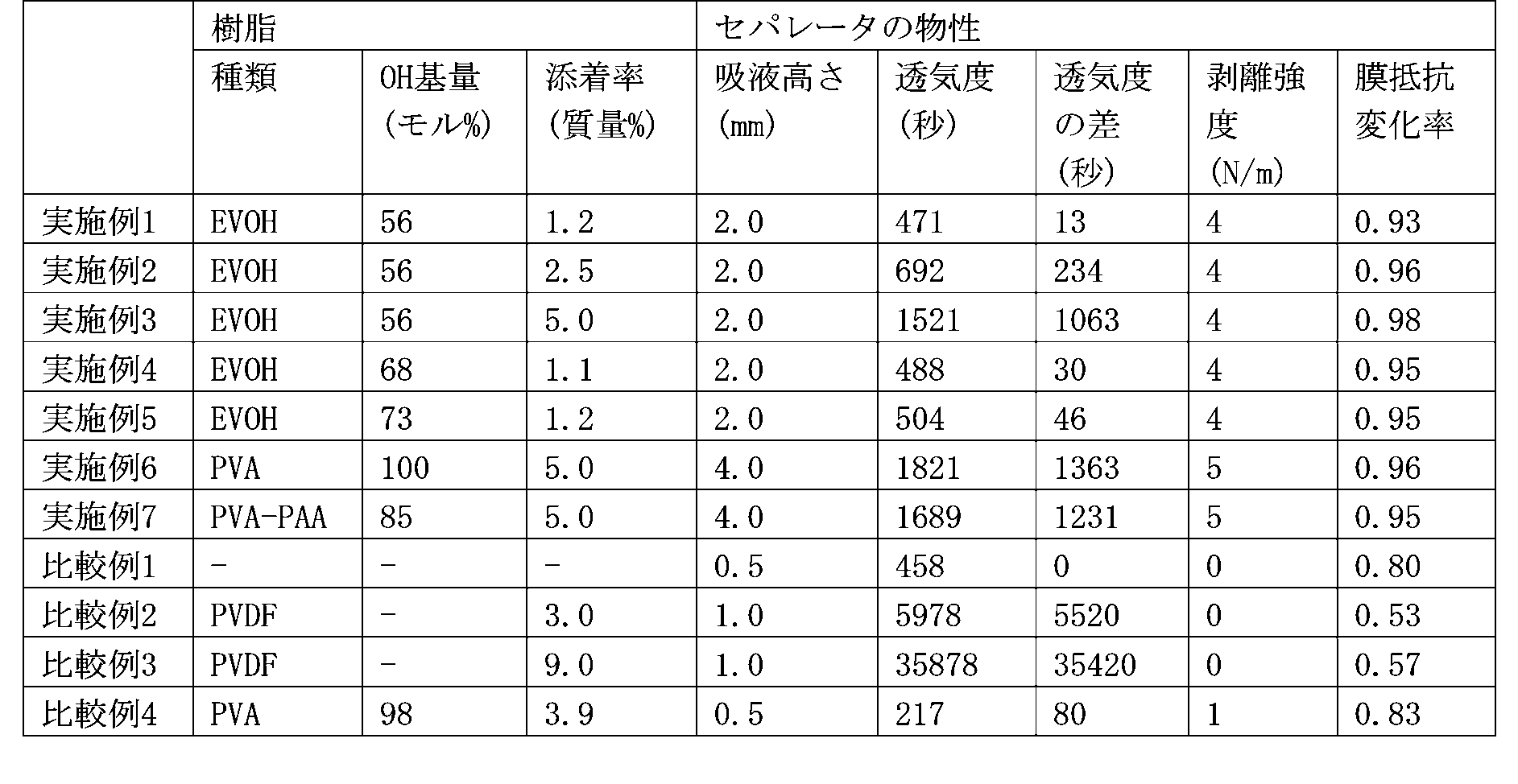
表1に示される通り、実施例1~7で得られたセパレータは、比較例1~4と比べ、膜抵抗変化率が1に近いことが確認された。よって、本願発明のセパレータは、電池製造時に短時間で内部抵抗を安定化させることができる。
Claims (7)
- 多孔質基材と、該多孔質基材の少なくとも一方の面にポリビニルアルコール系樹脂を含む添着層とを有し、体積比1:1:1のエチレンカーボネート/エチルメチルカーボネート/ジメチルカーボネートを混合溶媒とする1.0 MのLiPF6溶液を1分間吸液させた際の吸液高さが1.2mm以上である、非水電解質二次電池用セパレータ。
- 前記セパレータの透気度から前記多孔質基材の透気度を引いた値は1~5000秒である、請求項1に記載の非水電解質二次電池用セパレータ。
- 前記添着層の割合は、前記セパレータの質量に対して8質量%以下である、請求項1又は2に記載の非水電解質二次電池用セパレータ。
- 25℃、線圧40kg/cmの条件下、天然黒鉛とスチレンブタジエンゴムとカルボキシメチルセルロースとを98:1:1の割合で含んでなる電極に、前記セパレータを圧着させた際の剥離強度は、2~10N/mである、請求項1~3のいずれかに記載の非水電解質二次電池用セパレータ。
- 前記ポリビニルアルコール系樹脂は、エチレン-ビニルアルコール系樹脂、ポリビニルアルコール、及びポリビニルアセタール系樹脂からなる群から選択される少なくとも1種である、請求項1~4のいずれかに記載の非水電解質二次電池用セパレータ。
- 多孔質基材と、該多孔質基材の少なくとも一方の面にポリビニルアルコール系樹脂を含む添着層とを有する非水電解質二次電池用セパレータの製造方法であって、
ポリビニルアルコール系樹脂を水含有溶媒に溶解させて、添着層形成用溶液を得る工程(I)、及び、凝固液により、該添着層形成用溶液から少なくともポリビニルアルコール系樹脂を凝固させて、多孔質基材の少なくとも一方の面に添着層を形成する工程(II)を含む、方法。 - 請求項1~5のいずれかに記載の非水電解質二次電池用セパレータを含む、非水電解質二次電池。
Applications Claiming Priority (2)
| Application Number | Priority Date | Filing Date | Title |
|---|---|---|---|
| JP2019-112131 | 2019-06-17 | ||
| JP2019112131A JP2022112528A (ja) | 2019-06-17 | 2019-06-17 | 非水電解質二次電池用セパレータ及びその製造方法 |
Publications (1)
| Publication Number | Publication Date |
|---|---|
| WO2020255802A1 true WO2020255802A1 (ja) | 2020-12-24 |
Family
ID=74040781
Family Applications (1)
| Application Number | Title | Priority Date | Filing Date |
|---|---|---|---|
| PCT/JP2020/022721 Ceased WO2020255802A1 (ja) | 2019-06-17 | 2020-06-09 | 非水電解質二次電池用セパレータ及びその製造方法 |
Country Status (2)
| Country | Link |
|---|---|
| JP (1) | JP2022112528A (ja) |
| WO (1) | WO2020255802A1 (ja) |
Citations (6)
| Publication number | Priority date | Publication date | Assignee | Title |
|---|---|---|---|---|
| WO1999031750A1 (fr) * | 1997-12-18 | 1999-06-24 | Mitsubishi Denki Kabushiki Kaisha | Adhesif pour elements, element l'utilisant et procede de fabrication d'elements |
| JP2009283273A (ja) * | 2008-05-22 | 2009-12-03 | Hitachi Maxell Ltd | 電池用セパレータおよび電池 |
| WO2011055596A1 (ja) * | 2009-11-09 | 2011-05-12 | 東レ株式会社 | 多孔性フィルムおよび蓄電デバイス |
| JP2015069957A (ja) * | 2013-10-01 | 2015-04-13 | 日立マクセル株式会社 | リチウムイオン二次電池用セパレータおよびその製造方法、並びにリチウムイオン二次電池およびその製造方法 |
| JP2017174647A (ja) * | 2016-03-24 | 2017-09-28 | 株式会社豊田中央研究所 | 電極構造体及びリチウム二次電池 |
| JP2018163872A (ja) * | 2017-03-03 | 2018-10-18 | 帝人株式会社 | 非水系二次電池用セパレータ及び非水系二次電池 |
-
2019
- 2019-06-17 JP JP2019112131A patent/JP2022112528A/ja active Pending
-
2020
- 2020-06-09 WO PCT/JP2020/022721 patent/WO2020255802A1/ja not_active Ceased
Patent Citations (6)
| Publication number | Priority date | Publication date | Assignee | Title |
|---|---|---|---|---|
| WO1999031750A1 (fr) * | 1997-12-18 | 1999-06-24 | Mitsubishi Denki Kabushiki Kaisha | Adhesif pour elements, element l'utilisant et procede de fabrication d'elements |
| JP2009283273A (ja) * | 2008-05-22 | 2009-12-03 | Hitachi Maxell Ltd | 電池用セパレータおよび電池 |
| WO2011055596A1 (ja) * | 2009-11-09 | 2011-05-12 | 東レ株式会社 | 多孔性フィルムおよび蓄電デバイス |
| JP2015069957A (ja) * | 2013-10-01 | 2015-04-13 | 日立マクセル株式会社 | リチウムイオン二次電池用セパレータおよびその製造方法、並びにリチウムイオン二次電池およびその製造方法 |
| JP2017174647A (ja) * | 2016-03-24 | 2017-09-28 | 株式会社豊田中央研究所 | 電極構造体及びリチウム二次電池 |
| JP2018163872A (ja) * | 2017-03-03 | 2018-10-18 | 帝人株式会社 | 非水系二次電池用セパレータ及び非水系二次電池 |
Also Published As
| Publication number | Publication date |
|---|---|
| JP2022112528A (ja) | 2022-08-03 |
Similar Documents
| Publication | Publication Date | Title |
|---|---|---|
| JP5545508B2 (ja) | 非水電解液リチウム二次電池 | |
| CN106163807B (zh) | 层叠多孔膜及非水电解液二次电池 | |
| CN106410096A (zh) | 非水电解液二次电池用间隔件、层叠间隔件、构件及非水电解液二次电池 | |
| JP2008179903A (ja) | 多孔質膜、電気化学素子用セパレータ、多孔質膜の製造方法、非水電解質電池および非水電解質電池の製造方法 | |
| CN106207058B (zh) | 一种非水系二次电池用隔膜 | |
| CN106163679B (zh) | 层叠多孔膜的制造方法 | |
| CN104335390A (zh) | 非水电解液二次电池间隔件的制造方法 | |
| KR20160142341A (ko) | 세퍼레이터의 제조 방법 | |
| KR20160144369A (ko) | 적층 다공질 필름 및 비수 전해액 이차 전지 | |
| JP6303871B2 (ja) | セパレータおよびリチウムイオン二次電池 | |
| JP7608008B2 (ja) | リチウム二次電池用セパレーター及びこれを備えたリチウム二次電池 | |
| CN113224466A (zh) | 一种压敏高分子改性隔膜及其制备方法和应用 | |
| CN103746086A (zh) | 一种聚对苯撑苯并双噁唑多孔膜及其制备方法和应用 | |
| JP2021166118A (ja) | 非水電解質電池電極用バインダー、非水電解質電池電極用バインダー溶液、非水電解質電池電極用スラリー組成物、非水電解質電池用電極及び非水電解質電池 | |
| JP2014026946A (ja) | 非水電解質電池用セパレータ及び非水電解質電池 | |
| JP2021044153A (ja) | 非水電解質電池用セパレータ | |
| WO2021193444A1 (ja) | 非水電解質電池用セパレータ | |
| KR102865418B1 (ko) | 리튬 이차 전지용 분리막 및 이의 제조방법 | |
| JP2023003220A (ja) | 非水電解質電池用セパレータ | |
| JP2019110125A (ja) | 非水電解質電池電極用バインダー溶液 | |
| JP7729479B2 (ja) | エネルギー貯蔵デバイス電極用薄膜形成組成物 | |
| JP2020167097A (ja) | 蓄電デバイス電極用バインダー、蓄電デバイス電極用スラリー組成物、蓄電デバイス用電極及び蓄電デバイス | |
| WO2020255802A1 (ja) | 非水電解質二次電池用セパレータ及びその製造方法 | |
| JP2001102089A (ja) | 固体状電解質、電気化学素子、リチウムイオン二次電池および電気二重層キャパシタ | |
| JP2001110449A (ja) | イオン伝導性シート |
Legal Events
| Date | Code | Title | Description |
|---|---|---|---|
| 121 | Ep: the epo has been informed by wipo that ep was designated in this application |
Ref document number: 20826354 Country of ref document: EP Kind code of ref document: A1 |
|
| NENP | Non-entry into the national phase |
Ref country code: DE |
|
| 122 | Ep: pct application non-entry in european phase |
Ref document number: 20826354 Country of ref document: EP Kind code of ref document: A1 |
|
| NENP | Non-entry into the national phase |
Ref country code: JP |