WO2020255674A1 - 付着物除去装置及び付着物除去方法 - Google Patents
付着物除去装置及び付着物除去方法 Download PDFInfo
- Publication number
- WO2020255674A1 WO2020255674A1 PCT/JP2020/021251 JP2020021251W WO2020255674A1 WO 2020255674 A1 WO2020255674 A1 WO 2020255674A1 JP 2020021251 W JP2020021251 W JP 2020021251W WO 2020255674 A1 WO2020255674 A1 WO 2020255674A1
- Authority
- WO
- WIPO (PCT)
- Prior art keywords
- exhaust port
- exhaust
- valve body
- exhaust pipe
- deposits
- Prior art date
- Legal status (The legal status is an assumption and is not a legal conclusion. Google has not performed a legal analysis and makes no representation as to the accuracy of the status listed.)
- Ceased
Links
Images




Classifications
-
- C—CHEMISTRY; METALLURGY
- C30—CRYSTAL GROWTH
- C30B—SINGLE-CRYSTAL GROWTH; UNIDIRECTIONAL SOLIDIFICATION OF EUTECTIC MATERIAL OR UNIDIRECTIONAL DEMIXING OF EUTECTOID MATERIAL; REFINING BY ZONE-MELTING OF MATERIAL; PRODUCTION OF A HOMOGENEOUS POLYCRYSTALLINE MATERIAL WITH DEFINED STRUCTURE; SINGLE CRYSTALS OR HOMOGENEOUS POLYCRYSTALLINE MATERIAL WITH DEFINED STRUCTURE; AFTER-TREATMENT OF SINGLE CRYSTALS OR A HOMOGENEOUS POLYCRYSTALLINE MATERIAL WITH DEFINED STRUCTURE; APPARATUS THEREFOR
- C30B31/00—Diffusion or doping processes for single crystals or homogeneous polycrystalline material with defined structure; Apparatus therefor
- C30B31/06—Diffusion or doping processes for single crystals or homogeneous polycrystalline material with defined structure; Apparatus therefor by contacting with diffusion material in the gaseous state
- C30B31/16—Feed and outlet means for the gases; Modifying the flow of the gases
-
- B—PERFORMING OPERATIONS; TRANSPORTING
- B08—CLEANING
- B08B—CLEANING IN GENERAL; PREVENTION OF FOULING IN GENERAL
- B08B9/00—Cleaning hollow articles by methods or apparatus specially adapted thereto
- B08B9/02—Cleaning pipes or tubes or systems of pipes or tubes
- B08B9/027—Cleaning the internal surfaces; Removal of blockages
-
- B—PERFORMING OPERATIONS; TRANSPORTING
- B08—CLEANING
- B08B—CLEANING IN GENERAL; PREVENTION OF FOULING IN GENERAL
- B08B13/00—Accessories or details of general applicability for machines or apparatus for cleaning
-
- B—PERFORMING OPERATIONS; TRANSPORTING
- B08—CLEANING
- B08B—CLEANING IN GENERAL; PREVENTION OF FOULING IN GENERAL
- B08B5/00—Cleaning by methods involving the use of air flow or gas flow
- B08B5/04—Cleaning by suction, with or without auxiliary action
-
- B—PERFORMING OPERATIONS; TRANSPORTING
- B08—CLEANING
- B08B—CLEANING IN GENERAL; PREVENTION OF FOULING IN GENERAL
- B08B9/00—Cleaning hollow articles by methods or apparatus specially adapted thereto
- B08B9/02—Cleaning pipes or tubes or systems of pipes or tubes
- B08B9/027—Cleaning the internal surfaces; Removal of blockages
- B08B9/032—Cleaning the internal surfaces; Removal of blockages by the mechanical action of a moving fluid, e.g. by flushing
- B08B9/035—Cleaning the internal surfaces; Removal of blockages by the mechanical action of a moving fluid, e.g. by flushing by suction
-
- C—CHEMISTRY; METALLURGY
- C30—CRYSTAL GROWTH
- C30B—SINGLE-CRYSTAL GROWTH; UNIDIRECTIONAL SOLIDIFICATION OF EUTECTIC MATERIAL OR UNIDIRECTIONAL DEMIXING OF EUTECTOID MATERIAL; REFINING BY ZONE-MELTING OF MATERIAL; PRODUCTION OF A HOMOGENEOUS POLYCRYSTALLINE MATERIAL WITH DEFINED STRUCTURE; SINGLE CRYSTALS OR HOMOGENEOUS POLYCRYSTALLINE MATERIAL WITH DEFINED STRUCTURE; AFTER-TREATMENT OF SINGLE CRYSTALS OR A HOMOGENEOUS POLYCRYSTALLINE MATERIAL WITH DEFINED STRUCTURE; APPARATUS THEREFOR
- C30B15/00—Single-crystal growth by pulling from a melt, e.g. Czochralski method
-
- C—CHEMISTRY; METALLURGY
- C30—CRYSTAL GROWTH
- C30B—SINGLE-CRYSTAL GROWTH; UNIDIRECTIONAL SOLIDIFICATION OF EUTECTIC MATERIAL OR UNIDIRECTIONAL DEMIXING OF EUTECTOID MATERIAL; REFINING BY ZONE-MELTING OF MATERIAL; PRODUCTION OF A HOMOGENEOUS POLYCRYSTALLINE MATERIAL WITH DEFINED STRUCTURE; SINGLE CRYSTALS OR HOMOGENEOUS POLYCRYSTALLINE MATERIAL WITH DEFINED STRUCTURE; AFTER-TREATMENT OF SINGLE CRYSTALS OR A HOMOGENEOUS POLYCRYSTALLINE MATERIAL WITH DEFINED STRUCTURE; APPARATUS THEREFOR
- C30B29/00—Single crystals or homogeneous polycrystalline material with defined structure characterised by the material or by their shape
- C30B29/02—Elements
- C30B29/06—Silicon
-
- C—CHEMISTRY; METALLURGY
- C30—CRYSTAL GROWTH
- C30B—SINGLE-CRYSTAL GROWTH; UNIDIRECTIONAL SOLIDIFICATION OF EUTECTIC MATERIAL OR UNIDIRECTIONAL DEMIXING OF EUTECTOID MATERIAL; REFINING BY ZONE-MELTING OF MATERIAL; PRODUCTION OF A HOMOGENEOUS POLYCRYSTALLINE MATERIAL WITH DEFINED STRUCTURE; SINGLE CRYSTALS OR HOMOGENEOUS POLYCRYSTALLINE MATERIAL WITH DEFINED STRUCTURE; AFTER-TREATMENT OF SINGLE CRYSTALS OR A HOMOGENEOUS POLYCRYSTALLINE MATERIAL WITH DEFINED STRUCTURE; APPARATUS THEREFOR
- C30B35/00—Apparatus not otherwise provided for, specially adapted for the growth, production or after-treatment of single crystals or of a homogeneous polycrystalline material with defined structure
-
- B—PERFORMING OPERATIONS; TRANSPORTING
- B08—CLEANING
- B08B—CLEANING IN GENERAL; PREVENTION OF FOULING IN GENERAL
- B08B2209/00—Details of machines or methods for cleaning hollow articles
- B08B2209/02—Details of apparatuses or methods for cleaning pipes or tubes
- B08B2209/027—Details of apparatuses or methods for cleaning pipes or tubes for cleaning the internal surfaces
- B08B2209/032—Details of apparatuses or methods for cleaning pipes or tubes for cleaning the internal surfaces by the mechanical action of a moving fluid
-
- C—CHEMISTRY; METALLURGY
- C30—CRYSTAL GROWTH
- C30B—SINGLE-CRYSTAL GROWTH; UNIDIRECTIONAL SOLIDIFICATION OF EUTECTIC MATERIAL OR UNIDIRECTIONAL DEMIXING OF EUTECTOID MATERIAL; REFINING BY ZONE-MELTING OF MATERIAL; PRODUCTION OF A HOMOGENEOUS POLYCRYSTALLINE MATERIAL WITH DEFINED STRUCTURE; SINGLE CRYSTALS OR HOMOGENEOUS POLYCRYSTALLINE MATERIAL WITH DEFINED STRUCTURE; AFTER-TREATMENT OF SINGLE CRYSTALS OR A HOMOGENEOUS POLYCRYSTALLINE MATERIAL WITH DEFINED STRUCTURE; APPARATUS THEREFOR
- C30B13/00—Single-crystal growth by zone-melting; Refining by zone-melting
Definitions
- the present invention relates to a deposit removing device and a deposit removing method for removing deposits adhering to an exhaust pipe that discharges gas from a chamber for producing a semiconductor crystal.
- the semiconductor crystal manufacturing apparatus includes, for example, a single crystal growth method of the Czochralski method (hereinafter abbreviated as "CZ method”) or the floating zone melting method (Floating zone method, hereinafter abbreviated as “FZ method”). There is one that manufactures semiconductor crystals using.
- CZ method Czochralski method
- FZ method floating zone melting method
- a silicon single crystal is pulled up from a silicon melt melted in a quartz crucible provided in a chamber to produce the silicon single crystal.
- oxygen (O 2 ) is dissolved from a quartz crucible containing silicon dioxide (SiO 2 ) and reacts with a silicon melt to generate silicon oxide (SiOx) or silicon dioxide (SiO 2 ). ..
- the silicon oxide (SiOx) or the silicon dioxide (SiO 2 ) evaporates from the surface of the silicon melt.
- the silicon oxide (SiOx), silicon dioxide (SiO 2 ), and the dopant described later that have evaporated from the surface of the silicon melt are generically referred to, the term "evaporate" is used.
- SiOx In silicon oxide (SiOx), x takes a value of 0 ⁇ x ⁇ 2. Silicon oxide (SiOx) is produced because sufficient oxygen (O 2 ) is not present in the silicon melt and in the atmosphere in the chamber as compared with the silicon molecule (S), so that the silicon molecule (S) is completely absent. This is because it is not oxidized.
- the evaporation reaches the inner wall surface of the chamber above the surface of the silicon melt, and a part of it adheres there.
- this deposit falls and melts in the silicon melt and is incorporated into the silicon single crystal being pulled up, defects (for example, dislocation) may occur in the produced silicon single crystal.
- the semiconductor crystal manufacturing apparatus is provided with an intake pipe for introducing the inert gas into the chamber, an exhaust pipe for discharging the inert gas to the outside of the chamber, a vacuum pump for discharging the inert gas from the exhaust pipe, and the like.
- the inert gas includes not only rare gas group elements such as argon (Ar) and helium (He) but also gases having low chemical reactivity such as nitrogen (N 2 ).
- the evaporation that reaches the exhaust pipe from the chamber in the high temperature atmosphere is gradually cooled as it passes through the exhaust pipe, and a part of the evaporation is discharged to the outside, but a part of the evaporation adheres to the inner wall surface of the exhaust pipe and accumulates. I will go.
- the silicon oxide (SiOx), silicon dioxide (SiO 2 ), and the dopant described later which are attached to the inner wall surface of the exhaust pipe are generically referred to, the term “adhesion” is used.
- the thickness of the deposits on the inner wall surface of the exhaust pipe increases as the number of times the silicon single crystal is pulled up increases.
- This deposit removing method includes an air introduction step and an atmospheric discharge step.
- the air introduction step the vacuum pump is stopped by the semiconductor crystal manufacturing apparatus in which the silicon single crystal is pulled up a predetermined number of times, and in this state, the crucible is removed and then the inside of the chamber is opened to the atmosphere.
- the atmosphere flows into the exhaust pipes, and the surface layer of the deposits on the inner wall of each exhaust pipe burns.
- an on-off valve is attached to each of a plurality of communication holes that are bored in the base plate that constitutes the bottom of the chamber and communicate with the exhaust pipe, and suction is provided in a system separate from the vacuum pump with each on-off valve open. Drive the pump. As a result, the atmosphere flows into each exhaust pipe from the chamber side, the deposits on each exhaust pipe are burned, the combustibles are peeled off, and suction is performed by the suction pump.
- a dopant may be added to the silicon melt.
- Dopants include, for example, n-type dopants typified by arsenic (As), phosphorus (P) and antimony (Sb), and n-type dopants typified by, for example, boron (B) and aluminum (Al). ..
- the boiling point of the n-type dopant is lower than the melting point of silicon, it easily evaporates from the surface of the silicon melt in the process of producing the silicon single crystal.
- the concentration of the n-type dopant in the silicon melt may be lower than the set value, and the produced silicon single crystal may not have desired properties (for example, resistivity).
- the pressure in the chamber is set higher than the low pressure of several thousand Pa.
- the pressure inside the chamber was set to a low pressure of several thousand Pa in order to prevent the evaporation from the surface of the silicon melt from reaching the inner wall surface of the chamber. If the pressure in the chamber is set high, the concentration of evaporation in the exhaust pipe becomes high. In this case, the amount of deposits on the inner wall surface of the exhaust pipe is larger than that when the dopant is not added and when the p-type dopant is added. Therefore, the possibility that the problems shown in (1) to (4) above will occur is further increased.
- the deposits adhering to the inner wall of the exhaust pipe come into contact with only a small amount of oxygen existing in the atmosphere, so that only the surface thereof is burned.
- a large amount of unburned deposits may remain.
- the adhesion to the inner wall of the exhaust pipe is strong, so that the deposits may not be sufficiently removed only by the air introduction step.
- oxygen (O 2 ) may be rapidly supplied to the unburned deposits due to the pressure fluctuation, causing spontaneous combustion or dust explosion. There is.
- the present invention has been made in view of the above-mentioned circumstances, and an example of the problem is to solve the above-mentioned problems.
- the deposit removing device of the present invention relates to a deposit removing device that removes deposits adhering to an exhaust pipe that discharges gas from a chamber for producing a semiconductor crystal, and communicates with the exhaust pipe.
- a valve body that opens and closes an exhaust port, an isolation space forming portion that accommodates the valve body and allows an inert gas to be introduced, and the exhaust port can be isolated from the outside, and a first that drives the valve body.
- the exhaust port opening / closing means having the driving means of the above and the second driving means for driving at least a part of the isolated space forming portion is provided, and the valve body is driven by the first driving means to drive the exhaust port. Is opened and closed, and at least a part of the isolated space forming portion is driven by the second driving means to introduce the atmosphere into the isolated space forming portion.
- the exhaust port is closed by bringing the valve body into contact with the base plate surface on which the exhaust port is formed, and the exhaust port is opened by separating the valve body from the base plate surface. It is preferable that
- the deposit removing method of the present invention relates to a deposit removing method for removing deposits adhering to an exhaust pipe that discharges gas from a chamber for producing a semiconductor crystal, and isolates an exhaust port communicating with the exhaust pipe from the outside.
- the exhaust port is opened in a state where the inert gas is introduced into the isolated space and the deposits are sucked from the outside of the chamber through the exhaust pipe.
- the exhaust port is closed by bringing the valve body into contact with the base plate surface on which the exhaust port is formed, and the exhaust port is opened by separating the valve body from the base plate surface.
- the deposits can be appropriately removed while suppressing the ignition of the deposits on the inner wall of the exhaust pipe.
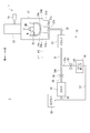
- FIG. 1 is a conceptual diagram showing an example of the configuration of the deposit removing device 2 according to the embodiment of the present invention
- FIG. 2 is a front view showing an example of the configuration of the exhaust port opening / closing means 51a constituting the deposit removing device 2.
- FIG. 3 is a conceptual diagram showing an example of the configuration of the semiconductor crystal manufacturing apparatus 1 to which the deposit removing apparatus 2 is applied.
- the semiconductor crystal manufacturing apparatus 1 manufactures a silicon single crystal by using the CZ method.
- the semiconductor crystal manufacturing apparatus 1 includes a semiconductor crystal manufacturing unit 11 and a gas exhaust unit 12.
- the semiconductor crystal manufacturing unit 11 is installed on the floor FC of the clean room CR.
- the semiconductor crystal manufacturing unit 11 includes a hollow chamber 21 having upper and lower ends open, a single crystal pulling unit 22 connected to the upper end of the chamber 21, and a gas introducing unit 23 for introducing an inert gas or air into the chamber 21.
- the chamber 21 accommodates a substantially bottomed cylindrical crucible 25 that stores the silicone melt M.
- the chamber 21 has a driving means for moving the crucible 25 up and down while rotating, a heater arranged outside the crucible 25 at a predetermined interval to heat the silicon melt M, and outside the heater. Accommodates heat insulating cylinders arranged at predetermined intervals.
- the single crystal pulling unit 22 pulls up the silicon single crystal SM by immersing the seed crystal (not shown) in the silicon melt M in the crucible 25 and then pulling it up while rotating it in a predetermined direction.
- the base plate BP (see FIGS. 2 and 4) that constitutes the bottom of the chamber 21 and is placed on the floor FC has a plurality of exhausts in order to exhaust the inert gas and the atmosphere introduced into the chamber 21 to the outside.
- the exhaust ports 24a to 24d are shown directly on the floor FC and in a straight line at predetermined intervals.
- the exhaust ports 24a to 24d are actually the upper surfaces of the base plate BP, and are formed at positions that are substantially symmetrical with each other with respect to the central axis of the crucible 25 in a plan view. This also applies to FIG.
- the upper surface of the base plate BP corresponds to the "base plate surface" in claims 3 and 6.
- the gas exhaust unit 12 is installed under the floor FC of the clean room CR and under the floor FP of the pump room PR. Under the floor FC of the base plate BP and the clean room CR, a plurality of communication holes 79 extending vertically downward and penetrating under the floor FC with the exhaust ports 24a to 24d at the upper ends, respectively, and four in the first embodiment. Communication holes 79a to 79d are bored. Each end of each of the four exhaust pipes 31a to 31d extending in the vertically downward direction is connected to each lower end of the communication holes 79a to 79d. The communication holes 79a are shown in FIGS. 2 and 4, but the communication holes 79b to 79d are not shown.
- the other ends of the exhaust pipes 31a to 31d are collectively connected to one end of the exhaust pipe 32.
- the other end of the exhaust pipe 32 is connected to the input end of the trap 33.
- the trap 33 peels off from the inner walls of the exhaust pipes 31a to 31d and captures the peeled material that has passed through the exhaust pipe 32.
- the output end of the trap 33 is connected to one end of the exhaust pipe 34.
- the exhaust pipe 34 is piped from under the floor FC of the clean room CR to under the floor FP of the pump room PR.
- the exhaust pipe 34 is branched into a branch pipe 34a and a branch pipe 34b in the middle of being piped under the floor FP of the pump chamber PR.
- One end of the branch pipe 34a is connected to the input end of the main valve 35 which is opened when the silicon single crystal is manufactured and closed when the deposit is removed.
- the output end of the main valve 35 is connected to the input end of the main pump 36 via the exhaust pipe 43.
- the main pump 36 operates during the production of a silicon single crystal, sucks inert gas, evaporators and dust that have passed through the exhaust pipe 43, and supplies the inert gas, evaporation, and dust to the scrubber 38 via the exhaust pipe 37.
- One end of the exhaust pipe 37 is connected to the output end of the main pump 36, and the other end is connected to the scrubber 38.
- the scrubber 38 mud deposits that have passed through the exhaust pipe 37 and the exhaust pipe 42 described later.
- One end of the branch pipe 34b is connected to the input end of the sub valve 39 which is opened when the deposit is removed and closed when the silicon single crystal is manufactured.
- the output end of the sub valve 39 is connected to the input end of the blower 41 via the exhaust pipe 40.
- the blower 41 operates when the deposits are removed, sucks the air, the inert gas, dust and the deposits that have passed through the exhaust pipe 40, and supplies the blower 41 to the scrubber 38 via the exhaust pipe 42 and the exhaust pipe 37.
- One end of the exhaust pipe 42 is connected to the output end of the blower 41, and the other end is connected to the vicinity of the other end of the exhaust pipe 37.
- FIG. 1 an example of the configuration of the deposit removing device 2 will be described with reference to FIGS. 1 and 2.
- the parts corresponding to the parts of FIG. 3 are designated by the same reference numerals, and the description thereof will be omitted.
- an exhaust port opening / closing section 13 is newly provided in place of the semiconductor crystal manufacturing section 11 shown in FIG. That is, the deposit removing device 2 includes an exhaust port opening / closing unit 13 and the gas exhaust unit 12.
- the deposit removing device 2 is configured by removing the semiconductor crystal manufacturing unit 11 from the floor FC of the clean room CR and then installing the exhaust port opening / closing unit 13.
- the base plate BP of the semiconductor crystal manufacturing unit 11 is still placed on the floor FC.
- the exhaust port opening / closing unit 13 includes exhaust port opening / closing means 51a to 51d for opening / closing the corresponding exhaust ports 24a to 24d, a controller 52 for controlling the exhaust port opening / closing means 51a to 51d, and an exhaust port opening / closing means 51a to for inert gas. It is provided with a gas introduction unit 53 to be introduced into the 51d. Similar to a general computer, the controller 52 includes an internal storage device in which a program for performing processing according to the timing chart shown in FIG. 7 is stored in advance, a memory in which the program is expanded, and a CPU for executing the program. Mainly prepare. However, in the operation description of the deposit removing device 2 described later, the specific processing of the controller 52 is not particularly described.
- the gas introduction unit 53 As the gas introduction unit 53, the gas introduction unit 23 constituting the semiconductor crystal manufacturing unit 11 may be used as it is.
- the gas introduction unit 53 and the exhaust port opening / closing means 51a to 51d are described as being directly connected by a pipe.
- an electromagnetic valve is provided between the gas introduction unit 53 and the exhaust port opening / closing means 51a to 51d, and the controller 52 opens / closes the solenoid valve.
- the substantially disk-shaped base plate 61 is provided with a substantially cylindrical communication hole 61a in the center, and a substantially disk-shaped gasket 62 is attached to the lower surface thereof.
- the outer diameter of the gasket 62 is substantially equal to the outer diameter of the base plate 61.
- the upper end of the substantially cylindrical fitting cylinder 63 is recessed and attached to the outer periphery of the communication hole 61a on the lower surface of the base plate 61.
- the fitting cylinder 63 fits into the exhaust port 24a and the communication hole 79a formed in the base plate BP placed on the floor FC of the clean room CR.
- FIG. 2 shows only the lower columns 64a and 64b.
- a substantially disk-shaped fixing base 65 is attached to each upper end of the lower columns 64a to 64d.
- a sealing cover 66 which is substantially cylindrical and has an open lower portion and most of the upper portion is placed.
- the upper opening of the sealing cover 66 is formed so that the upper columns 71a to 71d and the pipes 70a to 70d, which will be described later, can project upward.
- the inner diameter of the sealing cover 66 is slightly larger than the outer diameter of the fixing base 65. Therefore, when the cylinder 73 described later operates, the sealing cover 66 lowers and the lower surface of the sealing cover 66 comes into contact with the upper surface of the fixing base 65, and when the cylinder 67 described later operates, the valve body 69 lowers. When it comes into contact with the peripheral edge of the exhaust port 24a, the space created by the inner wall of the sealing cover 66, the upper surface of the base plate 61, and the upper surface of the valve body 69 is sealed.
- the sealed cover 66 is used to form a sealed space in the exhaust port 24a, but can be paraphrased as being used to isolate the exhaust port 24a from the outside. Therefore, in claim 1, the term "isolated space forming portion" is used.
- a nearly cylindrical communication hole is drilled in the center of the fixing base 65.
- a cylinder 67 is attached to the center of the upper surface of the fixing base 65 by projecting the rod 68 downward from the communication hole.
- a substantially disk-shaped valve body 69 is horizontally attached to the lower end of the rod 68.
- the valve body 69 faces the exhaust port 24a, and the outer diameter of the valve body 69 is slightly larger than the inner diameter of the exhaust port 24a. Therefore, when the cylinder 67 operates and pushes out the rod 68, the valve body 69 is lowered and the lower surface of the valve body 69 comes into contact with the peripheral edge of the exhaust port 24a, the exhaust port 24a is closed. On the other hand, when the cylinder 67 is operated to accommodate the rod 68 in the cylinder 67 and the valve body 69 is moved upward, the exhaust port 24a is opened.
- FIG. 1 shows only the pipes 70a and 70b.
- the other ends of the pipes 70a to 70d are connected to the four output ends of the gas introduction unit 53. That is, the inert gas is supplied from the gas introduction portion 53 to the space created by the inner wall of the sealing cover 66 and the upper surface of the base plate 61 via the pipes 70a to 70d.
- FIG. 2 shows only the upper columns 71a and 71b.
- a substantially disk-shaped upper mounting plate 72 is attached to each upper end of the upper columns 71a to 71d.
- a substantially cylindrical communication hole is bored in the center of the upper mounting plate 72.
- a cylinder 73 is attached to the center of the upper surface of the upper mounting plate 72 by projecting the rod 74 upward from the communication hole.
- a substantially cross-shaped connecting plate 75 is attached to the upper end of the rod 74. Further, the handle 76 is attached to the upper surface of the upper mounting plate 72 at a position where it does not interfere with the vertical movement of the connecting plate 75.
- FIG. 2 shows only the linear shafts 77a and 77b.
- four substantially cylindrical communication holes are located at positions symmetrical with respect to the central axis of the cylinder 73 and corresponding to the four linear shafts 77a to 77d. Has been drilled.
- linear bushes 78a to 78d are attached to each of these four communication holes.
- the linear bushes 78a to 78d are substantially cylindrical, and an open flange is formed at the upper end.
- the linear bushes 78a to 78d are attached to the connecting plate 75 so that the lower surface of each flange abuts on the upper surface of the connecting plate 75 and the lower end protrudes below the connecting plate 75.
- FIG. 2 shows only the linear bushes 78a and 78b.
- the linear shafts 77a to 77d are interposed in the corresponding linear bushes 78a to 78d, and their lower ends are attached to the upper surface of the sealing cover 66. That is, the linear shafts 77a to 77d are vertically movablely attached to the corresponding linear bushes 78a to 78d. Therefore, when the connecting plate 75 is pushed upward by operating the cylinder 73 and pushing the rod 74 upward, the sealing cover 66 moves upward. Therefore, as shown in FIG. 4, the inner wall of the sealing cover 66 and the base plate The atmosphere flows into the space created by the upper surface of the 61.
- the operation of the deposit removing device having the above configuration will be described with reference to the drawings.
- the main valve 35 is opened and the sub valve 39 is closed.
- the main pump 36 is operated and the blower 41 is stopped.
- the silicon single crystal SM finally manufactured is taken out.
- the predetermined time is, for example, several hundred hours required to produce a silicon single crystal 10 times.
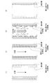
- FIG. 5 (1) schematically shows one of the exhaust pipes 31a to 31d. The same applies to FIGS. 5 (2) to (4) and 6 (1) to (4).
- deposits having different physical and chemical states adhere to the inner wall of the exhaust pipe.
- deposits having different physical states are dust, a freshly adhered evaporator, and a deposit as a solid after the evaporation.
- deposits having different chemical states are those in which oxidation is sufficiently advanced and are in a chemically stable state, and those in which they are in a chemically unstable state during oxidation.
- FIGS. 5 and 6 show only two types of deposits, one that has been oxidized and one that is in the process of being oxidized.
- both the main pump 36 and the blower 41 are stopped, and the main valve 35 and the sub valve 39 are also closed. Therefore, the difference between the pressure in the exhaust pipes 31a to 31d and the atmospheric pressure is not large. Therefore, the atmosphere existing in the clean room CR flows into the exhaust pipes 31a to 31d relatively slowly, so that there is little risk of ignition or dust explosion.
- each valve body 69 of the exhaust port opening / closing means 51a to 51d is held upward as shown by a solid line in FIG. Further, as shown in FIG. 2, the lower surface of each of the airtight covers 66 of the exhaust port opening / closing means 51a to 51d is kept in contact with the upper surface of the fixing base 65.
- the deposits adhering to the inner walls of the communication holes 79a to 79d near the exhaust ports 24a to 24d are scraped off and fall into the exhaust pipes 31a to 31d.
- the fallen object sequentially moves in the exhaust pipes 31a to 31d and 32 by a later process and is captured by the trap 33.
- the operator connects the exhaust port opening / closing means 51a to 51d and the controller 52, and attaches the other ends of the pipes 70a to 70d of the exhaust port opening / closing means 51a to 51d to the output ends of the gas introduction unit 53. Connecting.
- the deposit removal process is performed according to the timing chart shown in FIG.
- the inert gas and the atmosphere are introduced into the exhaust pipes 31a to 31d, the blower 41 is operated, and each of the sealing covers 66 constituting the exhaust port opening / closing means 51a to 51d is raised (all). (See FIG. 4) is represented as “ON”.
- the introduction of the inert gas and the atmosphere into the exhaust pipes 31a to 31d is stopped, the blower 41 is stopped, and the sealing covers 66 constituting the exhaust port opening / closing means 51a to 51d are all lowered to seal.
- Bringing the lower end of the cover 66 into contact with the upper surface of the base plate 61 (see FIG. 2) is represented as “OFF”.
- the valve bodies 69 constituting the exhaust port opening / closing means 51a are represented as the first on-off valve, and similarly, the valve bodies 69 constituting the exhaust port opening / closing means 51b to 51d are referred to as the second to fourth valves, respectively. It is expressed as an on-off valve.
- the introduction of the inert gas (for example, nitrogen (N 2 ) gas) is started at the time Tb shown in FIG.
- the flow rate of the inert gas is, for example, 200 L / min.
- the space created by the inner wall of the sealing cover 66 of the exhaust port opening / closing means 51a to 51d, the upper surface of the base plate 61, and the upper surface of the valve body 69 is filled with the inert gas.
- the valve body 69 is in contact with the peripheral edges of the exhaust ports 24a to 24d and the blower 41 is operating, the pressure in the exhaust pipes 31a to 31d is in a negative pressure state lower than the atmospheric pressure.
- the first on-off valve that is, the valve body 69 of the exhaust port opening / closing means 51a is raised by the period T2 and then lowered.
- the period T2 is preferably, for example, 1 to 2 seconds.
- the pressure of the inert gas fluctuates in the exhaust pipe 31a. Therefore, as shown in FIG. 5 (3), the oxidized deposits adhering to the inner wall of the exhaust pipe 31a are peeled off and the inert gas flows in. And move downstream on the airflow generated by the operation of the blower 41.
- the second on-off valve that is, the valve body 69 of the exhaust port opening / closing means 51b is raised by the period T2 and then lowered.
- the blower 41 Since the blower 41 is operating at time Tc, the amount of air is larger than that shown in FIG. 5 (1). However, the state shown in FIG. 6 (1) has less chemically unstable deposits as compared with the state shown in FIG. 5 (1) immediately after the production of the silicon single crystal, so that ignition or powder explosion may occur. It's even less.
- the first on-off valve that is, the valve body 69 of the exhaust port opening / closing means 51a is raised by the period T4 and then lowered.
- the period T4 is preferably, for example, 1 to 2 seconds.
- the pressure of the atmosphere fluctuates in the exhaust pipe 31a. Therefore, as shown in FIG. 6 (3), most of the oxidized deposits adhering to the inner wall of the exhaust pipe 31a are peeled off, and the inflow of the atmosphere and the blower 41 It moves downstream on the airflow generated by the operation of.
- the second on-off valve that is, the valve body 69 of the exhaust port opening / closing means 51b is raised by the period T4 and then lowered.
- the individual exhaust port opening / closing means 51a to 51d are installed in the exhaust ports 24a to 24d, and not only the opening / closing of the exhaust ports 24a to 24d but also the exhaust of the inert gas or the atmosphere.
- the introduction to the tubes 31a to 31d is also controlled individually. Therefore, it is superior in the following points as compared with the prior art in which the introduction of the inert gas or the atmosphere into the exhaust pipe of the atmosphere is performed through the chamber.
- the inert gas can be intensively introduced into the exhaust pipes 31a to 31d via the pipes 70a to 70d and the small-capacity sealing cover 66, and the introduction can be stopped in a short time. Therefore, a large pressure fluctuation of the inert gas can be generated in the exhaust pipes 31a to 31d, and even a deposit having a strong adhesive force such as an n-type dopant can be easily removed.
- the inert gas may be filled in the small-capacity sealing cover instead of the large-capacity chamber, the amount of the inert gas used is small and the filling time can be shortened. Therefore, the cost and working time of the deposit removing work can be reduced as compared with the conventional technique.
- the exhaust port opening / closing means 51a to 51d can be installed in the spacious clean room CR, so that workability is good and deposits are temporarily deposited. Even if a fire or dust explosion occurs, workers can evacuate immediately, which is highly safe.
- the chemically unstable deposits immediately after the production of the silicon single crystal adhering to the inner walls of the exhaust pipes 31a to 31d are removed by an inert gas containing no oxygen, and thus ignite. And the risk of powder explosion is extremely low.
- Embodiment 2 In the first removing step of the first embodiment described above, as shown in FIG. 7, the first on-off valve to the fourth on-off valve are opened for a short period of time, and then the first on-off valve to the fourth on-off valve are opened again.
- An example of short-term opening of the on-off valve is shown, but the present invention is not limited to this.
- the first on-off valve may be opened a plurality of times, and then the second on-off valve and thereafter may be opened a plurality of times.
- the order of opening and closing the first on-off valve to the fourth on-off valve is not particularly limited.
- Embodiment 3 In the first removing step of the above-described first and second embodiments, as shown in FIG. 7, only one on-off valve is opened for a short period of time, and then only the other on-off valve is opened for a short period of time after the lapse of the period T1. Although shown, it is not limited to this. A plurality of on-off valves may be opened for a short period of time at the same time without elapse of the period T1. By doing so, the working time can be shortened.
- Embodiment 4 In the first embodiment described above, an example in which the atmosphere is introduced by raising the sealing cover 66 using the cylinder 73 has been shown, but the present invention is not limited to this.
- the atmosphere may be introduced by lowering the fixed base 65.
- the sealing cover 66 and the fixing base 65 correspond to "at least a part of the isolated space forming portion" in claim 1.
- the semiconductor crystal is a silicon single crystal
- the semiconductor crystal may be any of silicon polycrystal, GaAs single crystal, GaAs polycrystal, InP single crystal, InP polycrystal, ZnS single crystal, ZnS polycrystal, ZnSe single crystal, and ZnSe polycrystal.
- the present invention is not limited to this, and the present invention is a semiconductor crystal using the FZ method. Of course, it can also be applied when manufacturing.
- exhaust ports 24a to 24d are formed on the base plate BP placed on the floor FC of the clean room CR, and exhaust port opening / closing means 51a to 51d are installed in the exhaust ports 24a to 24d.
- the present invention is not limited to this.
- the present invention can also be applied to, for example, when two, three or five or more exhaust ports are formed on the side wall of the base plate BP or the clean room CR.
- cylinders 67 and 73 may be either an air cylinder or a hydraulic cylinder, or the cylinders 67 and 73 may be replaced with solenoids.
- each of the above-described embodiments examples of attaching the exhaust port opening / closing means 51a to 51d to the exhaust ports 24a to 24d formed on the base plate BP are shown, but the present invention is not limited to this.
- the base plate BP may also be removed, and the exhaust port opening / closing means 51a to 51d may be directly attached to the opening formed in the floor FC of the clean room CR, which communicates with the exhaust ports 24a to 24d.
- each of the above-described embodiments can be diverted from each other as long as there is no particular contradiction or problem in the purpose and configuration thereof.
- Base plate 61a ... Communication hole, 62 ... Gasket, 63 ... Fitting cylinder, 64a- 64d ... Lower support, 65 ... Fixed base, 66 ... Sealed cover (isolated space forming part), 67, 73 ... Cylinder, 68, 74 ... Rod, 69 ... Valve body, 70a to 70d ... Piping, 71a to 71d ... Upper support , 72 ... Upper mounting plate, 75 ... Connecting plate, 76 ... Handle, 77a-77d ... Linear shaft, 78a-78d ... Linear bush, 79a-79d ... Communication hole, BP ... Base plate, CR ... Clean room, FC, FP ... Floor , M ... Silicon melt, PR ... Pump chamber, SM ... Silicon single crystal.
Landscapes
- Chemical & Material Sciences (AREA)
- Engineering & Computer Science (AREA)
- Crystallography & Structural Chemistry (AREA)
- Materials Engineering (AREA)
- Metallurgy (AREA)
- Organic Chemistry (AREA)
- Mechanical Engineering (AREA)
- Crystals, And After-Treatments Of Crystals (AREA)
Abstract
開示される付着物除去装置は、半導体結晶を製造するチャンバからガスを排出する排気管に付着する付着物を除去する。排気管に連通する排気口(24a)を開閉する弁体(69)と、弁体(69)を収容し、不活性ガスが導入可能であり、排気口(24a)を外部から隔離可能とする密閉カバー(66)及び固定台(65)と、弁体(69)を駆動するシリンダ(67)と、密閉カバー(66)又は固定台(65)を駆動するシリンダ(73)とを有する排気口開閉手段(51a)を備える。シリンダ(67)により弁体(69)を駆動して排気口(24a)を開閉し、シリンダ(73)により密閉カバー(66)又は固定台(65)を駆動して密閉カバー(66)へ大気を導入する。
Description
本発明は、半導体結晶を製造するチャンバからガスを排出する排気管に付着する付着物を除去する付着物除去装置及び付着物除去方法に関する。
半導体結晶製造装置には、例えば、チョクラルスキー法(Czochralski method、以下「CZ法」と略す。)や浮遊帯域融解法(Floating zone method、以下「FZ法」と略す。)の単結晶成長法を用いて半導体結晶を製造するものがある。
CZ法では、例えば、チャンバ内に設けられた石英坩堝で溶融されたシリコン融液からシリコン単結晶を引き上げて製造する。この製造過程において、二酸化シリコン(SiO2)を成分とする石英坩堝から酸素(O2)が溶け出してシリコン融液と反応し、酸化シリコン(SiOx)又は二酸化シリコン(SiO2)が生成される。前記酸化シリコン(SiOx)又は前記二酸化シリコン(SiO2)は、シリコン融液表面から蒸発する。以下、シリコン融液表面から蒸発した酸化シリコン(SiOx)、二酸化シリコン(SiO2)及び後述するドーパントを総称する際は、「蒸発物」という用語を用いる。
酸化シリコン(SiOx)において、xは0<x<2の値をとる。酸化シリコン(SiOx)が生成されるのは、シリコン分子(S)と比較して十分な酸素(O2)がシリコン融液中及びチャンバ内雰囲気に存在しないため、シリコン分子(S)が完全に酸化されないからである。
前記蒸発物は、シリコン融液表面上方のチャンバ内壁面に到達し、一部がそこに付着する。この付着物が落下してシリコン融液に溶融し、引き上げ中のシリコン単結晶に取り込まれた場合、製造されたシリコン単結晶に欠陥(例えば、有転位化)が生じるおそれがある。
このような不都合を防止するために、通常、チャンバ内の圧力を数千Paの低圧に維持しつつ、不活性ガスをチャンバ上方から導入し、前記蒸発物がチャンバ内壁面に到達する前に前記蒸発物をチャンバ外に排出している。このため、半導体結晶製造装置には、不活性ガスをチャンバ内に導入する吸気管と、チャンバ外に排出する排気管と、排気管から不活性ガスを排出する真空ポンプなどが設けられている。ここで、不活性ガスは、アルゴン(Ar)、ヘリウム(He)に代表される希ガス族元素だけでなく、窒素(N2)に代表される化学反応性の低いガスも含む。
高温雰囲気のチャンバから排気管に到達した前記蒸発物は、排気管内を通過するに従って次第に冷却され、一部は外部に排出されるが、一部は排気管の内壁面に付着して堆積していく。以下、排気管の内壁面に付着した酸化シリコン(SiOx)、二酸化シリコン(SiO2)及び後述するドーパントを総称する際は、「付着物」という用語を用いる。排気管の内壁面の付着物は、シリコン単結晶の引き上げ回数が増えれば増えるほど、その厚みを増していく。
排気管の内壁面に付着物が付着したままであると、以下に示す様々な問題が発生することがある。
(1)付着物がチャンバ内に逆流してシリコン融液に混入し、製造されたシリコン単結晶に欠陥(例えば、有転位化)が発生する。
(1)付着物がチャンバ内に逆流してシリコン融液に混入し、製造されたシリコン単結晶に欠陥(例えば、有転位化)が発生する。
(2)付着物で内径が小さくなった排気管の配管抵抗が大きくなるため、チャンバ内の圧力が制御し難くなりチャンバ内の圧力が大きく変動しやすい。これにより、シリコン単結晶の引上げ条件に悪影響がでたり、排気管の内壁面から剥離した付着物が排気管の下流にある機器(例えば、真空ポンプ)の内部に浸入してその機器を損傷したりする。
(3)シリコン単結晶の引き上げ終了後チャンバ内を大気に開放した際又はその後付着物を除去する際に、酸化途中の酸化シリコン(SiOx)に急激に酸素(O2)が供給されて自然発火や粉塵爆発が発生するおそれがある。
(3)シリコン単結晶の引き上げ終了後チャンバ内を大気に開放した際又はその後付着物を除去する際に、酸化途中の酸化シリコン(SiOx)に急激に酸素(O2)が供給されて自然発火や粉塵爆発が発生するおそれがある。
(4)大径のシリコン単結晶を製造する場合、小径のシリコン単結晶を製造する場合と比較して石英坩堝内のシリコン融液の量が多いため、排気管内の蒸発物濃度も高い。このため、排気管の内壁面に付着する付着物の量は、小径のシリコン単結晶を製造する場合と比較して多い。したがって、前記(1)~(3)に示す問題が発生するおそれは高くなる。
そこで、前記問題を解決するために、本出願人は、以前、以下に示す付着物除去方法を提案した。この付着物除去方法は、大気導入工程及び大気排出工程を有する。大気導入工程では、所定回数シリコン単結晶を引き上げた半導体結晶製造装置で真空ポンプを停止し、この状態で坩堝を取り外した後チャンバ内を大気に開放する。これにより、排気管に大気が流入し、各排気管内壁の付着物の表層が燃焼する。
次に、チャンバの底部を構成するベースプレートに穿設され、排気管に連通する複数の連通孔にそれぞれ開閉弁を取り付け、各開閉弁を開いた状態で真空ポンプとは別系統に設けられた吸引ポンプを駆動する。これにより、大気がチャンバ側から各排気管に流入して各排気管の付着物が燃焼し、燃焼物が剥離して吸引ポンプによって吸引される。
大気排出工程では、吸引ポンプを駆動した状態ですべての開閉弁を閉じて排気管内を負圧にした後、いずれか1つの開閉弁を開閉する。これにより、当該排気管内の圧力が大気圧に戻る圧力変動が生じて大気が当該排気管に流入するので、当該排気管の内壁面に残留する付着物が燃焼する。これと同時に、前記圧力変動により大気排出工程と比較して強い剥離力が生じるため、当該排気管の内壁面に残留する燃焼物が剥離して吸引ポンプによって吸引される。他の排気管についても同様の処理を行う(例えば、特許文献1参照)。
ところで、シリコン単結晶に所望の性質を付与するために、ドーパントをシリコン融液に添加する場合がある。ドーパントには、例えば、ヒ素(As)、リン(P)及びアンチモン(Sb)に代表されるn型ドーパントと、例えば、ホウ素(B)、アルミニウム(Al)に代表されるn型ドーパントとがある。
n型ドーパントは、その沸点がシリコンの融点よりも低いので、前記シリコン単結晶の製造過程において、シリコン融液表面から蒸発しやすい。この結果、シリコン融液内のn型ドーパントの濃度が設定値より下がり、製造されたシリコン単結晶が所望の性質(例えば、抵抗率)が得られなくなるおそれがある。このような不都合を防止するために、n型ドーパントを添加する場合、チャンバ内の圧力は前記数千Paの低圧より高めに設定する。
しかし、チャンバ内の圧力は、そもそもシリコン融液表面から蒸発した蒸発物がチャンバ内壁面に到達することを防止するために数千Paの低圧に設定されていた。このチャンバ内の圧力を高めに設定すると、排気管内の蒸発物濃度が高くなる。この場合、排気管の内壁面の付着物の量は、ドーパントを添加しない場合及びp型ドーパントを添加する場合と比較して多い。したがって、前記(1)~(4)に示す問題が発生するおそれはより一層高まる。
この点、前記した従来の付着物除去方法の大気導入工程では、排気管の内壁に付着した付着物は、大気中に存在する少量の酸素だけと接触するため、その表面のみが燃焼するに過ぎず、未燃焼の付着物が多く残留するおそれがある。また、付着物が厚いと排気管内壁への固着力が強いため、大気導入工程だけでは付着物が十分に除去されないおそれがある。さらに、未燃焼の付着物が多く露出した状態で大気排出工程を行うと、前記圧力変動によって未燃焼の付着物に急激に酸素(O2)が供給されて自然発火や粉塵爆発が発生するおそれがある。
本発明は、上述した事情に鑑みてなされたものであり、上述のような問題を解決することを課題の一例とするものであり、これらの課題を解決することができる付着物除去装置及び付着物除去方法を提供することを目的とする。
前記課題を解決するために、本発明の付着物除去装置は、半導体結晶を製造するチャンバからガスを排出する排気管に付着する付着物を除去する付着物除去装置に係り、前記排気管に連通する排気口を開閉する弁体と、前記弁体を収容し、不活性ガスが導入可能であり、前記排気口を外部から隔離可能とする隔離空間形成部と、前記弁体を駆動する第1の駆動手段と、前記隔離空間形成部の少なくとも一部を駆動する第2の駆動手段とを有する排気口開閉手段を備え、前記第1の駆動手段により、前記弁体を駆動して前記排気口を開閉し、前記第2の駆動手段により、前記隔離空間形成部の少なくとも一部を駆動して前記隔離空間形成部へ大気を導入するように構成されたことを特徴としている。
本発明では、前記チャンバを大気に開放した状態で、前記排気管に付着する付着物を除去することが好ましい。
また本発明では、前記弁体を前記排気口が形成されたベースプレート面に当接させることにより前記排気口を閉じ、前記弁体を前記ベースプレート面から離間させることにより前記排気口を開けるように構成されたことが好ましい。
本発明の付着物除去方法は、半導体結晶を製造するチャンバからガスを排出する排気管に付着する付着物を除去する付着物除去方法に係り、前記排気管に連通する排気口を外部から隔離し、かつ、隔離した空間に不活性ガスを導入し、前記付着物を前記排気管を介して前記チャンバ外から吸引している状態で、前記排気口を開けることを特徴としている。
本発明では、前記チャンバを大気に開放した状態で、前記排気管に付着する付着物を除去することが好ましい。
また本発明では、弁体を前記排気口が形成されたベースプレート面に当接させることにより前記排気口を閉じ、前記弁体を前記ベースプレート面から離間させることにより前記排気口を開けることが好ましい。
本発明によれば、n型ドーパントを添加したシリコン単結晶を製造する場合でも、排気管内壁の付着物の発火を抑制しつつ、付着物を適切に除去することができる。
以下、図面を参照して本発明を実施するための形態について説明する。
実施の形態1.
図1は本発明の実施1の形態に係る付着物除去装置2の構成の一例を示す概念図、図2は付着物除去装置2を構成する排気口開閉手段51aの構成の一例を示す正面図である。また、図3は付着物除去装置2が適用される半導体結晶製造装置1の構成の一例を示す概念図である。
実施の形態1.
図1は本発明の実施1の形態に係る付着物除去装置2の構成の一例を示す概念図、図2は付着物除去装置2を構成する排気口開閉手段51aの構成の一例を示す正面図である。また、図3は付着物除去装置2が適用される半導体結晶製造装置1の構成の一例を示す概念図である。
まず、半導体結晶製造装置1の構成の一例を図3を参照して説明する。半導体結晶製造装置1は、CZ法を用いてシリコン単結晶を製造する。半導体結晶製造装置1は、半導体結晶製造部11と、ガス排気部12とを備えている。
半導体結晶製造部11は、クリーンルームCRの床FC上に設置される。半導体結晶製造部11は、上下端が開口し中空のチャンバ21と、チャンバ21の上端に接続する単結晶引き上げ部22と、不活性ガスや大気をチャンバ21内に導入するガス導入部23とを備えている。チャンバ21は、シリコン融液Mを貯留するほぼ有底円筒形状の坩堝25を収容する。図3には示さないが、チャンバ21は、坩堝25を回転させつつ昇降させる駆動手段と、坩堝25の外側に所定間隔を隔てて配置されシリコン融液Mを加熱するヒータと、ヒータの外側に所定間隔を隔てて配置された保温筒を収容する。単結晶引き上げ部22は、図示せぬ種結晶を坩堝25内のシリコン融液Mに浸漬した後、所定方向に回転させつつ引き上げることにより、シリコン単結晶SMを引き上げる。
チャンバ21の底部を構成し、床FCに載置されるベースプレートBP(図2及び4参照)には、チャンバ21内に導入された不活性ガスや大気を外部に排気するために、複数の排気口24、この実施の形態1では、4つの排気口24a~24dがそれぞれ形成されている。図3では、排気口24a~24dは、床FCに直接、かつ、一直線上に所定間隔を隔てて示されている。しかし、排気口24a~24dは、実際は、ベースプレートBPの上面であって、平面視において、坩堝25の中心軸に対し互いにほぼ対称となる位置に形成されている。このことは、図1についても同様である。ベースプレートBPの上面は、請求項3及び請求項6における「ベースプレート面」に対応している。
ガス排気部12は、クリーンルームCRの床FC下及びポンプ室PRの床FP下に設置されている。ベースプレートBP及びクリーンルームCRの床FC下には、前記排気口24a~24dをそれぞれ上端とし鉛直下方向に延びて床FC下へ貫通する、複数の連通孔79、この実施の形態1では、4本の連通孔79a~79dが穿設されている。連通孔79a~79dの各下端には、それぞれ鉛直下方向に延びる4本の排気管31a~31dの各一端がそれぞれ接続している。連通孔79aは図2及び図4に示しているが、連通孔79b~79dは図示していない。
排気管31a~31dの各他端は、集合して排気管32の一端に接続している。排気管32の他端は、トラップ33の入力端に接続している。トラップ33は、排気管31a~31dの内壁から剥離し、排気管32内を通過してきた剥離物を捕捉する。トラップ33の出力端は、排気管34の一端に接続している。
排気管34は、クリーンルームCRの床FC下からポンプ室PRの床FP下に配管されている。排気管34は、ポンプ室PRの床FP下に配管された途中で分岐配管34aと分岐配管34bに分岐している。分岐配管34aの一端は、シリコン単結晶製造時に開かれ、付着物除去時は閉じられるメインバルブ35の入力端に接続している。メインバルブ35の出力端は、排気管43を経てメインポンプ36の入力端に接続している。メインポンプ36は、シリコン単結晶製造時に作動し、排気管43を通過してきた不活性ガス、蒸発物や粉塵を吸引して排気管37を経てスクラバ38へ供給する。排気管37は、一端がメインポンプ36の出力端に接続し、他端がスクラバ38に接続する。スクラバ38は、排気管37及び後述する排気管42を通過した付着物を泥化する。
分岐配管34bの一端は、付着物除去時に開かれ、シリコン単結晶製造時に閉じられるサブバルブ39の入力端に接続している。サブバルブ39の出力端は、排気管40を経てブロア41の入力端に接続している。ブロア41は、付着物除去時に作動し、排気管40を通過してきた大気、不活性ガス、粉塵や付着物を吸引して排気管42及び排気管37を経てスクラバ38へ供給する。排気管42は、一端がブロア41の出力端に接続し、他端が排気管37の他端近傍に接続する。
次に、図1及び図2を参照して、付着物除去装置2の構成の一例を説明する。図1において、図3の各部に対応する部分には同一の符号を付け、その説明を省略する。図1では、図3に示す半導体結晶製造部11に換えて、排気口開閉部13が新たに設けられている。すなわち、付着物除去装置2は、排気口開閉部13と、前記ガス排気部12とを備えている。言い換えると、付着物除去装置2は、クリーンルームCRの床FC上から半導体結晶製造部11を撤去した後、排気口開閉部13を設置することにより構成される。なお、半導体結晶製造部11のうち、ベースプレートBPは床FCに載置したままである。
排気口開閉部13は、対応する排気口24a~24dを開閉する排気口開閉手段51a~51dと、排気口開閉手段51a~51dを制御するコントローラ52と、不活性ガスを排気口開閉手段51a~51d内に導入するガス導入部53とを備えている。コントローラ52は、一般的なコンピュータと同様、図7に示すタイミングチャートに従った処理を行うためのプログラムが予め記憶された内部記憶装置、前記プログラムが展開されるメモリ、前記プログラムを実行するCPUを主として備える。ただし、後述する付着物除去装置2の動作説明では、コントローラ52の具体的な処理については特に説明しない。
なお、ガス導入部53は、半導体結晶製造部11を構成する前記ガス導入部23をそのまま用いても良い。図1では、ガス導入部53と排気口開閉手段51a~51dとは配管により直接接続されているように記載している。しかし、実際は、ガス導入部53と排気口開閉手段51a~51dとの間に電磁弁が設けられ、この電磁弁の開閉をコントローラ52が行う。
排気口開閉手段51a~51dは、同一構造及び同一機能を有しているので、排気口開閉手段51aの構造及び機能を図2を参照して説明する。ほぼ円盤状のベースプレート61は、中央にほぼ円筒状の連通孔61aが穿設され、下面にほぼ円盤状のガスケット62が取り付けられている。ガスケット62の外径は、ベースプレート61の外径にほぼ等しい。ベースプレート61下面の連通孔61a外周には、ほぼ円筒状の嵌合筒63の上端が没入して取り付けられている。嵌合筒63は、クリーンルームCRの床FCに載置されたベースプレートBPに形成された排気口24a及び連通孔79aに嵌合する。
ベースプレート61上面の連通孔61a近傍には、ベースプレート61の中心軸に対し互いに対象となる位置に、4本の下部支柱64a~64dが立設している。図2には、下部支柱64a及び64bのみ示す。下部支柱64a~64dの各上端には、ほぼ円盤状の固定台65が取り付けられている。固定台65には、ほぼ円筒状で下部が全面に開口し、上部の大部分が開口した密閉カバー66が載置されている。
密閉カバー66の上部開口は、いずれも後述する上部支柱71a~71d及び配管70a~70dが上方に突出可能に形成されている。しかし、密閉カバー66の内径が固定台65の外径より僅かに大きい。このため、後述するシリンダ73が作動することにより密閉カバー66が下降して密閉カバー66の下面が固定台65の上面に当接するとともに、後述するシリンダ67が作動することにより弁体69が下降して排気口24a周縁に当接した場合、密閉カバー66の内壁、ベースプレート61の上面及び弁体69の上面が作る空間は密閉状態となる。
すなわち、密閉カバー66は、排気口24aに密閉空間を形成するために用いられるが、排気口24aを外部から隔離するために用いられると言い換えることができる。そこで、請求項1では、「隔離空間形成部」という用語を用いている。
固定台65の中央にほぼ円筒状の連通孔が穿設されている。固定台65の上面中央には、そのロッド68を前記連通孔から下方に突出させてシリンダ67が取り付けられている。ロッド68の下端には、ほぼ円盤状の弁体69が水平に取り付けられている。弁体69は排気口24aに対向し、かつ、弁体69の外径は、排気口24aの内径より僅かに大きい。このため、シリンダ67が作動してロッド68を押し出すことにより、弁体69が下降して弁体69の下面が排気口24a周縁に当接した場合、排気口24aは閉状態となる。一方、シリンダ67が作動してロッド68をシリンダ67に収容することにより、弁体69を上方に移動させた場合、排気口24aは開状態となる。
固定台65のシリンダ67近傍には、シリンダ67の中心軸に対して互いに対象となる位置にほぼ円筒状の連通孔が4つ穿設され、各連通孔に4本の配管70a~70dの各一端がそれぞれ取り付けられている。図1には、配管70a及び70bのみ示す。配管70a~70dの各他端は、ガス導入部53の4つの出力端に接続される。すなわち、密閉カバー66の内壁とベースプレート61の上面とが作る空間には、ガス導入部53から配管70a~70dを介して不活性ガスが供給される。
固定台65上面のシリンダ67近傍には、シリンダ67の中心軸に対して互いに対象となる位置に、4本の上部支柱71a~71dが4本の下部支柱64a~64dと同軸上に立設している。図2には、上部支柱71a及び71bのみ示す。上部支柱71a~71dの各上端には、ほぼ円盤状の上部取付板72が取り付けられている。
上部取付板72の中央にほぼ円筒状の連通孔が穿設されている。上部取付板72の上面中央には、そのロッド74を前記連通孔から上方に突出させてシリンダ73が取り付けられている。ロッド74の上端には、ほぼ十字状の連結板75が取り付けられている。また、上部取付板72の上面であって、連結板75の上下動と干渉しない位置には、取っ手76が取り付けられている。
連結板75の4つの端部近傍には、4本のリニアシャフト77a~77dの各上端が取り付けられている。図2には、リニアシャフト77a及び77bのみ示す。上部取付板72の外縁部近傍には、シリンダ73の中心軸に対して互いに対象となる位置であって、4本のリニアシャフト77a~77dに対応した位置に、ほぼ円筒状の4つの連通孔が穿設されている。
これら4つの連通孔のそれぞれには、それぞれ4つのリニアブッシュ78a~78dが取り付けられている。リニアブッシュ78a~78dは、ほぼ円筒状であって、開口したフランジが上端に形成されている。リニアブッシュ78a~78dは、各フランジの下面が連結板75の上面に当接するとともに、下端が連結板75の下方に突出するように、連結板75に取り付けられている。図2には、リニアブッシュ78a及び78bのみ示す。
前記リニアシャフト77a~77dは、対応するリニアブッシュ78a~78dに介装され、各下端は密閉カバー66の上面に取り付けられている。つまり、前記リニアシャフト77a~77dは、対応するリニアブッシュ78a~78dに上下動自在に取り付けられている。したがって、シリンダ73が作動してロッド74を上方に押し出すことにより、連結板75を上方に押し上げると、密閉カバー66が上方に移動するので、図4に示すように、密閉カバー66の内壁とベースプレート61の上面とが作る空間に大気が流入する。
一方、シリンダ73が作動してロッド74をシリンダ73に収容することにより、連結板75を下方に引き戻すと、密閉カバー66が下降して密閉カバー66の下面が固定台65の上面に当接する。この時、シリンダ67が作動して弁体69を下降させ、図2に2点鎖線で示すように、排気口24a周縁に当接させていれば、密閉カバー66の内壁、ベースプレート61の上面及び弁体69の上面が作る空間は密閉状態となる。
次に、前記構成の付着物除去装置の動作を図面を参照して説明する。シリコン単結晶製造時は、図3に示す半導体結晶製造装置1において、メインバルブ35を開くとともに、サブバルブ39を閉じる。また、メインポンプ36を作動するとともに、ブロア41を停止しておく。この状態で半導体結晶製造装置1を所定時間稼働した後、最後に製造したシリコン単結晶SMを取り出す。前記所定時間は、例えば、10回シリコン単結晶を製造するのに要する数百時間である。
前記所定時間経過した後、メインポンプ36を停止するとともに、メインバルブ35を閉じる。この状態で、ベースプレートBPを残して半導体結晶製造部11を解体する。これにより、クリーンルームCR内に存在する大気は、図3に示す排気口24a~24dから、図5(1)に示すように、排気管31a~31dに流入する。図5(1)は、排気管31a~31dの1つを模式的に表したものである。図5(2)~(4)及び図6(1)~(4)も同様である。
半導体結晶製造装置1を所定時間稼働すると、排気管の内壁には、物理的にも化学的にも状態が異なる各種の付着物が付着する。例えば、物理的状態が異なる付着物は、粉塵、付着したばかりの蒸発物、蒸発物の付着後固体として析出したものである。一方、化学的状態が異なる付着物は、酸化が十分に進み化学的に安定した状態にあるもの、酸化途中で化学的に不安定な状態にあるものである。
しかし、図5及び図6には、説明の便宜上、付着物は、酸化したものと、酸化途中のものの2種類のみを示す。この段階では、メインポンプ36及びブロア41のいずれも停止しており、メインバルブ35及びサブバルブ39も閉じている。このため、排気管31a~31d内の圧力と大気圧との差は大きくない。したがって、クリーンルームCR内に存在する大気は、比較的緩やかに排気管31a~31dに流入するので、発火や粉塵爆発のおそれは少ない。
図5(1)の状態からある程度時間が経過すると、図5(2)に示すように、酸化途中の付着物のうち、表層部分は、酸化が十分に進んだ化学的に安定した状態となる。排気管31a~31dが図5(2)に示す状態になった後、図1に示すように、排気口開閉部13を設置する。
すなわち、作業者は、排気口開閉手段51a~51dの取っ手76を把持し、嵌合筒63を排気口24a~24d及び連通孔79a~79dに順次嵌合させる。この排気口開閉手段51a~51dの取付作業時には、排気口開閉手段51a~51dの各弁体69は、図2に実線で示すように、上方に保持しておく。また、排気口開閉手段51a~51dの各密閉カバー66は、図2に示すように、その下面を固定台65の上面に当接させた状態としておく。
前記取付作業により、排気口24a~24d近傍の連通孔79a~79dの各内壁に付着した付着物は削り取られ、排気管31a~31d内に落下する。この落下物は、後の処理により排気管31a~31d及び32内を順次移動してトラップ33で捕捉される。
次に、作業者は、排気口開閉手段51a~51dとコントローラ52とを接続するとともに、排気口開閉手段51a~51dの各配管70a~70dの各他端をガス導入部53の各出力端に接続する。
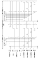
このような状態において、図7に示すタイミングチャートに従った付着物除去処理を行う。図7では、排気管31a~31d内に不活性ガス及び大気を導入すること、ブロア41を作動すること及び排気口開閉手段51a~51dをそれぞれ構成する各密閉カバー66をいずれも上昇させること(図4参照)を「ON」と表している。
一方、排気管31a~31d内への不活性ガス及び大気導入を停止すること、ブロア41を停止すること及び排気口開閉手段51a~51dをそれぞれ構成する各密閉カバー66をいずれも下降させて密閉カバー66の下端をベースプレート61上面に当接させること(図2参照)を「OFF」と表している。また、図7では、排気口開閉手段51aを構成する弁体69を第1の開閉弁と表し、同様に、排気口開閉手段51b~51dをそれぞれ構成する各弁体69を第2~第4の開閉弁と表している。
不活性ガス及び大気が導入されておらず、排気口開閉手段51a~51dのすべての密閉カバー66が下降した状態でブロア41を作動した後、図7に示す時刻Taに排気口開閉手段51a~51dのすべての弁体69を下降させて排気口24a~24d周縁に当接させることにより、密閉カバー66の内壁、ベースプレート61の上面及び弁体69の上面が作る空間を密閉状態とする。
次に、図7に示す時刻Tbに不活性ガス(例えば、窒素(N2)ガス)の導入を開始する。不活性ガスの流量は、例えば、200L/minである。これにより、排気口開閉手段51a~51dの密閉カバー66の内壁、ベースプレート61の上面及び弁体69の上面が作る空間に不活性ガスが充填される。一方、弁体69が排気口24a~24d周縁に当接しているとともに、ブロア41が作動しているため、排気管31a~31d内の圧力は大気圧より低い負圧の状態となる。その後、図7に示すように、第1の開閉弁、すなわち、排気口開閉手段51aの弁体69を期間T2だけ上昇させた後、下降させる。期間T2は、例えば、1~2秒間であることが好ましい。
これにより、排気管31a内で不活性ガスの圧力変動が生じるので、図5(3)に示すように、排気管31aの内壁に付着した酸化した付着物は、剥離し、不活性ガスの流入とブロワ41の作動によって生じた気流に乗って下流に移動する。前記期間T2及び期間T1を経過した後、図7に示すように、第2の開閉弁、すなわち、排気口開閉手段51bの弁体69を期間T2だけ上昇させた後、下降させる。
これにより、排気管31b内で不活性ガスの圧力変動が生じるので、図5(3)に示すように、排気管31bの内壁に付着した酸化した付着物は、剥離し、不活性ガスの流入とブロワ41の作動によって生じた気流に乗って下流に移動する。以下、第3及び第4の開閉弁についても同様の処理を行う。以上説明した一連の処理を第1~第4の開閉弁について、所定回数繰り返すことにより、排気管31a~31dの内壁に付着した酸化した付着物は、図5(4)に示すように、除去される。
次に、図7に示す時刻Tcになると、排気口開閉手段51a~51dのすべての弁体69をほぼ同時に上昇させるとともに、すべての密閉カバー66をほぼ同時に上昇させる。つまり、排気口開閉手段51a~51dは、いずれも図4に示す状態となる。この処理と前後して不活性ガスの導入を停止する。これにより、図6(1)に示すように、大気は、密閉カバー66の下方及び排気口24a~24dを経て排気管31a~31dへ導入される。
時刻Tcではブロア41が作動しているため、図5(1)に示す状態と比較して大気の量は多い。しかし、図6(1)に示す状態は、シリコン単結晶製造直後の図5(1)に示す状態と比較して、化学的に不安定な付着物が少ないため、発火や粉体爆発のおそれはさらに少ない。
図6(1)の状態からある程度時間が経過すると、図6(2)に示すように、排気管31a~31dの酸化途中の付着物のほとんどは、酸化が十分に進んだ化学的に安定した状態となる。
次に、図7に示す時刻Tdには、排気口開閉手段51a~51dのすべての密閉カバー66を上昇させたままで、排気口開閉手段51a~51dのすべての弁体69を下降させて排気口24a~24d周縁に当接させて排気口24a~24dを閉状態とする。これにより、ブロア41が作動しているため、排気管31a~31d内の圧力は大気圧より低い負圧の状態となる。
次に、図7に示すように、第1の開閉弁、すなわち、排気口開閉手段51aの弁体69を期間T4だけ上昇させた後、下降させる。期間T4は、例えば、1~2秒間であることが好ましい。
これにより、排気管31a内で大気の圧力変動が生じるので、図6(3)に示すように、排気管31aの内壁に付着した酸化した付着物は、ほとんど剥離し、大気の流入とブロワ41の作動によって生じた気流に乗って下流に移動する。前記期間T3及び期間T4を経過した後、図7に示すように、第2の開閉弁、すなわち、排気口開閉手段51bの弁体69を期間T4だけ上昇させた後、下降させる。
これにより、排気管31b内で大気の圧力変動が生じるので、図6(3)に示すように、排気管31bの内壁に付着した酸化した付着物は、剥離し、大気流入とブロワ41の作動によって生じた気流に乗って下流に移動する。以下、第3及び第4の開閉弁についても同様の処理を行う。以上説明した一連の処理を第1~第4の開閉弁について、所定回数繰り返すことにより、排気管31a~31dの内壁に付着した酸化した付着物は、図6(4)に示すように、ほとんど除去される。
このように、本発明の実施の形態1では、排気口24a~24dに個別の排気口開閉手段51a~51dを設置し、排気口24a~24dの開閉だけでなく、不活性ガス又は大気の排気管31a~31dへの導入も個別に制御している。したがって、不活性ガス又は大気の排気管への導入をチャンバを介して行う従来技術と比較して、以下の点で優れている。
(1)配管70a~70d及び小容量の密閉カバー66を介して排気管31a~31dへ集中的に不活性ガスを導入できるとともに、導入の停止も短時間で行うことができる。このため、排気管31a~31d内に不活性ガスの大きな圧力変動を発生させることができ、n型ドーパントのような固着力の強い付着物でも容易に除去することができる。
(2)大容量のチャンバではなく、小容量の密閉カバー内に不活性ガスを充填すれば良いので、不活性ガスの使用量が少ないとともに、充填時間も短縮することができる。このため、従来技術と比較して付着物除去作業の経費及び作業時間を削減することができる。
(2)大容量のチャンバではなく、小容量の密閉カバー内に不活性ガスを充填すれば良いので、不活性ガスの使用量が少ないとともに、充填時間も短縮することができる。このため、従来技術と比較して付着物除去作業の経費及び作業時間を削減することができる。
(3)チャンバを含めたシリコン単結晶製造に使用される装置や治具を取り除いた後広々としたクリーンルームCRに排気口開閉手段51a~51dを設置できるので、作業性が良いとともに、仮に付着物の発火や粉塵爆発が発生した場合でも、作業員は直ちに避難できるため、安全性が高い。
(4)本発明の実施の形態1では、排気管31a~31dの内壁に付着したシリコン単結晶製造直後で化学的に不安定な付着物は酸素を含有しない不活性ガスによって除去するので、発火や粉体爆発の危険は極めて低い。
実施の形態2.
上述の実施の形態1の第1の除去工程では、図7に示すように、第1の開閉弁から第4の開閉弁の短期開放を行った後、再度第1の開閉弁から第4の開閉弁の短期開放を行う例を示したが、これに限定されない。例えば、第1の開閉弁の短期開放を複数回行った後、第2の開閉弁以降の短期開放を複数回行っても良い。また、第1の開閉弁から第4の開閉弁を開閉する順序も特に限定されない。
上述の実施の形態1の第1の除去工程では、図7に示すように、第1の開閉弁から第4の開閉弁の短期開放を行った後、再度第1の開閉弁から第4の開閉弁の短期開放を行う例を示したが、これに限定されない。例えば、第1の開閉弁の短期開放を複数回行った後、第2の開閉弁以降の短期開放を複数回行っても良い。また、第1の開閉弁から第4の開閉弁を開閉する順序も特に限定されない。
実施の形態3.
上述の実施の形態1及び2の第1の除去工程では、図7に示すように、1つの開閉弁のみ短期開放を行った後、期間T1経過後に他の開閉弁のみ短期開放を行う例を示したが、これに限定されない。期間T1を経過することなく、複数の開閉弁の短期開放を同時に行っても良い。このようにすれば、作業時間を短縮することができる。
上述の実施の形態1及び2の第1の除去工程では、図7に示すように、1つの開閉弁のみ短期開放を行った後、期間T1経過後に他の開閉弁のみ短期開放を行う例を示したが、これに限定されない。期間T1を経過することなく、複数の開閉弁の短期開放を同時に行っても良い。このようにすれば、作業時間を短縮することができる。
実施の形態4.
上述の実施の形態1では、シリンダ73を用いて密閉カバー66を上昇させることにより大気を導入する例を示したが、これに限定されない。例えば、固定台65を下降させることにより大気を導入するように構成しても良い。密閉カバー66及び固定台65は、請求項1における「隔離空間形成部の少なくとも一部」に対応している。
上述の実施の形態1では、シリンダ73を用いて密閉カバー66を上昇させることにより大気を導入する例を示したが、これに限定されない。例えば、固定台65を下降させることにより大気を導入するように構成しても良い。密閉カバー66及び固定台65は、請求項1における「隔離空間形成部の少なくとも一部」に対応している。
以上、本発明の実施の形態について図面を参照して詳述してきたが、具体的な構成はこの実施の形態に限られるものではなく、本発明の要旨を逸脱しない範囲の設計の変更等があっても本発明に含まれる。
例えば、上述の各実施の形態では、半導体結晶がシリコン単結晶である例を示したが、これに限定されない。半導体結晶は、シリコン多結晶、GaAs単結晶、GaAs多結晶、InP単結晶、InP多結晶、ZnS単結晶、ZnS多結晶、ZnSe単結晶、ZnSe多結晶のいずれでも良い。また、上述の各実施の形態では、本発明をCZ法を用いて半導体結晶を製造する場合に適用する例を示したが、これに限定されず、本発明は、FZ法を用いて半導体結晶を製造する場合にももちろん適用することができる。
例えば、上述の各実施の形態では、半導体結晶がシリコン単結晶である例を示したが、これに限定されない。半導体結晶は、シリコン多結晶、GaAs単結晶、GaAs多結晶、InP単結晶、InP多結晶、ZnS単結晶、ZnS多結晶、ZnSe単結晶、ZnSe多結晶のいずれでも良い。また、上述の各実施の形態では、本発明をCZ法を用いて半導体結晶を製造する場合に適用する例を示したが、これに限定されず、本発明は、FZ法を用いて半導体結晶を製造する場合にももちろん適用することができる。
また、上述の各実施の形態では、クリーンルームCRの床FCに載置されたベースプレートBPに4つの排気口24a~24dが形成され、各排気口24a~24dに排気口開閉手段51a~51dを設置する例を示したが、これに限定されない。本発明は、例えば、ベースプレートBP又はクリーンルームCRの側壁に、2つ、3つ又は5つ以上の排気口が形成されている場合にも適用することができる。
また、上述の各実施の形態では、密閉カバー66及び弁体69の駆動にシリンダ67及び73を用いる例を示したが、これに限定されない。シリンダ67及び73は、エアシリンダ又は油圧シリンダのいずれでも良いし、シリンダ67及び73をソレノイドに換えても良い。
また、上述の各実施の形態では、ベースプレートBPに形成された排気口24a~24dに排気口開閉手段51a~51dを取り付ける例を示したが、これに限定されない。半導体結晶製造部11を解体する際にベースプレートBPも撤去し、排気口24a~24dと連通する、クリーンルームCRの床FCに形成された開口に排気口開閉手段51a~51dを直接取り付けても良い。
また、上述の各実施の形態は、その目的及び構成に特に矛盾や問題がない限り、互いの技術を流用することができる。
また、上述の各実施の形態は、その目的及び構成に特に矛盾や問題がない限り、互いの技術を流用することができる。
1…半導体結晶製造装置、2…付着物除去装置、11…半導体結晶製造部、12…ガス排気部、13…排気口開閉部、21…チャンバ、22…単結晶引き上げ部、23,53…ガス導入部、24a~24d…排気口、25…坩堝、31a~31d,32,34,37,40,42,43…排気管、34a,34b…分岐配管、33…トラップ、35…メインバルブ,36…メインポンプ、38…スクラバ、39…サブバルブ、41…ブロア、51a~51d…排気口開閉手段、52…コントローラ、61…ベースプレート、61a…連通孔、62…ガスケット、63…嵌合筒、64a~64d…下部支柱、65…固定台、66…密閉カバー(隔離空間形成部)、67,73…シリンダ、68,74…ロッド、69…弁体、70a~70d…配管、71a~71d…上部支柱、72…上部取付板、75…連結板、76…取っ手、77a~77d…リニアシャフト、78a~78d…リニアブッシュ、79a~79d…連通孔、BP…ベースプレート、CR…クリーンルーム、FC,FP…床、M…シリコン融液、PR…ポンプ室、SM…シリコン単結晶。
Claims (6)
- 半導体結晶を製造するチャンバからガスを排出する排気管に付着する付着物を除去する付着物除去装置であって、
前記排気管に連通する排気口を開閉する弁体と、
前記弁体を収容し、不活性ガスが導入可能であり、前記排気口を外部から隔離可能とする隔離空間形成部と、
前記弁体を駆動する第1の駆動手段と、
前記隔離空間形成部の少なくとも一部を駆動する第2の駆動手段とを有する排気口開閉手段を備え、
前記第1の駆動手段により、前記弁体を駆動して前記排気口を開閉し、
前記第2の駆動手段により、前記隔離空間形成部の少なくとも一部を駆動して前記隔離空間形成部へ大気を導入するように構成されたことを特徴とする付着物除去装置。 - 前記チャンバを大気に開放した状態で、前記排気管に付着する付着物を除去することを特徴とする請求項1に記載の付着物除去装置。
- 前記弁体を前記排気口が形成されたベースプレート面に当接させることにより前記排気口を閉じ、前記弁体を前記ベースプレート面から離間させることにより前記排気口を開けるように構成されたことを特徴とする請求項1又は2に記載の付着物除去装置。
- 半導体結晶を製造するチャンバからガスを排出する排気管に付着する付着物を除去する付着物除去方法であって、
前記排気管に連通する排気口を外部から隔離し、かつ、隔離した空間に不活性ガスを導入し、前記付着物を前記排気管を介して前記チャンバ外から吸引している状態で、前記排気口を開けることを特徴とする付着物除去方法。 - 前記チャンバを大気に開放した状態で、前記排気管に付着する付着物を除去することを特徴とする請求項4に記載の付着物除去方法。
- 弁体を前記排気口が形成されたベースプレート面に当接させることにより前記排気口を閉じ、前記弁体を前記ベースプレート面から離間させることにより前記排気口を開けることを特徴とする請求項4又は5に記載の付着物除去方法。
Priority Applications (4)
| Application Number | Priority Date | Filing Date | Title |
|---|---|---|---|
| KR1020217039651A KR102635496B1 (ko) | 2019-06-21 | 2020-05-28 | 부착물 제거 장치 및 부착물 제거 방법 |
| US17/620,559 US11639560B2 (en) | 2019-06-21 | 2020-05-28 | Deposit removing device and deposit removing method |
| DE112020002971.9T DE112020002971B4 (de) | 2019-06-21 | 2020-05-28 | Ablagerungsentfernungsvorrichtung und Ablagerungsentfernungsverfahren |
| CN202080045513.8A CN113966415B (zh) | 2019-06-21 | 2020-05-28 | 附着物去除装置及附着物去除方法 |
Applications Claiming Priority (2)
| Application Number | Priority Date | Filing Date | Title |
|---|---|---|---|
| JP2019115806A JP7167864B2 (ja) | 2019-06-21 | 2019-06-21 | 付着物除去装置及び付着物除去方法 |
| JP2019-115806 | 2019-06-21 |
Publications (1)
| Publication Number | Publication Date |
|---|---|
| WO2020255674A1 true WO2020255674A1 (ja) | 2020-12-24 |
Family
ID=73994238
Family Applications (1)
| Application Number | Title | Priority Date | Filing Date |
|---|---|---|---|
| PCT/JP2020/021251 Ceased WO2020255674A1 (ja) | 2019-06-21 | 2020-05-28 | 付着物除去装置及び付着物除去方法 |
Country Status (7)
| Country | Link |
|---|---|
| US (1) | US11639560B2 (ja) |
| JP (1) | JP7167864B2 (ja) |
| KR (1) | KR102635496B1 (ja) |
| CN (1) | CN113966415B (ja) |
| DE (1) | DE112020002971B4 (ja) |
| TW (1) | TWI730675B (ja) |
| WO (1) | WO2020255674A1 (ja) |
Citations (4)
| Publication number | Priority date | Publication date | Assignee | Title |
|---|---|---|---|---|
| JP2002305190A (ja) * | 2001-04-09 | 2002-10-18 | Tokyo Electron Ltd | 熱処理装置及びその清浄方法 |
| JP2003124205A (ja) * | 2001-10-15 | 2003-04-25 | Nec Kansai Ltd | 半導体製造装置 |
| WO2012131888A1 (ja) * | 2011-03-29 | 2012-10-04 | 株式会社Sumco | 半導体結晶製造装置用排気通路のクリーニング装置及びそのクリーニング方法 |
| JP2014214051A (ja) * | 2013-04-25 | 2014-11-17 | 三菱マテリアルテクノ株式会社 | 粉塵除去装置及び粉塵除去方法 |
Family Cites Families (11)
| Publication number | Priority date | Publication date | Assignee | Title |
|---|---|---|---|---|
| JPS54108387A (en) | 1978-02-15 | 1979-08-24 | Mitsubishi Chem Ind Ltd | Transporter of pulverulent and granular bodies |
| JPS5644861U (ja) | 1979-06-01 | 1981-04-22 | ||
| JP3846620B2 (ja) * | 2000-08-23 | 2006-11-15 | 信越半導体株式会社 | シリコン単結晶引上げ装置の解体方法および排ガス配管 |
| JP4423805B2 (ja) * | 2001-04-13 | 2010-03-03 | 信越半導体株式会社 | シリコン単結晶の製造装置並びに製造方法 |
| JP2002316889A (ja) * | 2001-04-18 | 2002-10-31 | Sumitomo Mitsubishi Silicon Corp | 排ガス配管内付着物の除去方法、及び単結晶引き上げ装置 |
| JP2004224606A (ja) * | 2003-01-21 | 2004-08-12 | Sumitomo Mitsubishi Silicon Corp | 単結晶引上装置の粉塵除去装置および方法 |
| TWI397617B (zh) * | 2010-02-12 | 2013-06-01 | Masahiro Hoshino | Metal silicon purification device |
| JP2012066948A (ja) * | 2010-09-21 | 2012-04-05 | Covalent Materials Corp | シリコン単結晶引上装置のクリーニング方法 |
| JP2012148906A (ja) * | 2011-01-17 | 2012-08-09 | Sumco Techxiv株式会社 | 単結晶引き上げ装置の生成物燃焼方法 |
| JP6219848B2 (ja) * | 2012-12-28 | 2017-10-25 | 株式会社Screenホールディングス | 処理装置とその排気切換装置並びに排気切換ユニットと切換弁ボックス |
| JP6828674B2 (ja) | 2017-12-20 | 2021-02-10 | 株式会社Sumco | クリーニング方法、シリコン単結晶の製造方法、および、クリーニング装置 |
-
2019
- 2019-06-21 JP JP2019115806A patent/JP7167864B2/ja active Active
-
2020
- 2020-03-16 TW TW109108562A patent/TWI730675B/zh active
- 2020-05-28 CN CN202080045513.8A patent/CN113966415B/zh active Active
- 2020-05-28 KR KR1020217039651A patent/KR102635496B1/ko active Active
- 2020-05-28 US US17/620,559 patent/US11639560B2/en active Active
- 2020-05-28 WO PCT/JP2020/021251 patent/WO2020255674A1/ja not_active Ceased
- 2020-05-28 DE DE112020002971.9T patent/DE112020002971B4/de active Active
Patent Citations (4)
| Publication number | Priority date | Publication date | Assignee | Title |
|---|---|---|---|---|
| JP2002305190A (ja) * | 2001-04-09 | 2002-10-18 | Tokyo Electron Ltd | 熱処理装置及びその清浄方法 |
| JP2003124205A (ja) * | 2001-10-15 | 2003-04-25 | Nec Kansai Ltd | 半導体製造装置 |
| WO2012131888A1 (ja) * | 2011-03-29 | 2012-10-04 | 株式会社Sumco | 半導体結晶製造装置用排気通路のクリーニング装置及びそのクリーニング方法 |
| JP2014214051A (ja) * | 2013-04-25 | 2014-11-17 | 三菱マテリアルテクノ株式会社 | 粉塵除去装置及び粉塵除去方法 |
Also Published As
| Publication number | Publication date |
|---|---|
| US11639560B2 (en) | 2023-05-02 |
| DE112020002971T5 (de) | 2022-03-03 |
| TWI730675B (zh) | 2021-06-11 |
| CN113966415B (zh) | 2024-02-23 |
| TW202100820A (zh) | 2021-01-01 |
| KR102635496B1 (ko) | 2024-02-07 |
| US20220267929A1 (en) | 2022-08-25 |
| KR20220003092A (ko) | 2022-01-07 |
| JP2021001095A (ja) | 2021-01-07 |
| DE112020002971B4 (de) | 2024-10-17 |
| JP7167864B2 (ja) | 2022-11-09 |
| CN113966415A (zh) | 2022-01-21 |
Similar Documents
| Publication | Publication Date | Title |
|---|---|---|
| US9376763B2 (en) | Manufacturing method and manufacturing apparatus of a group III nitride crystal, utilizing a melt containing a group III metal, an alkali metal, and nitrogen | |
| JPH0794488A (ja) | 真空処理装置集合体のクリーニング方法 | |
| TWI707423B (zh) | 清洗方法、矽單結晶的製造方法及清洗裝置 | |
| WO2020255674A1 (ja) | 付着物除去装置及び付着物除去方法 | |
| JPWO2007013464A1 (ja) | 半導体装置の製造方法 | |
| US9003832B2 (en) | Method of making a silica crucible in a controlled atmosphere | |
| KR101567663B1 (ko) | 잉곳성장장비의 배기장치 및 이를 이용한 잉곳성장방법 | |
| US12327724B2 (en) | Vapor deposition device and method of producing epitaxial wafer | |
| JP2003309070A (ja) | シリコンエピタキシャルウェーハの製造方法 | |
| JP2002316889A (ja) | 排ガス配管内付着物の除去方法、及び単結晶引き上げ装置 | |
| JPH0794489A (ja) | 処理装置のクリーニング方法 | |
| JP2000124140A (ja) | 窒化物系iii−v族化合物半導体の結晶成長方法 | |
| JP2011011942A (ja) | 結晶製造装置及び結晶製造方法 | |
| JP3791450B2 (ja) | 有機薄膜の蒸着方法 | |
| JP2608533B2 (ja) | 単結晶薄膜半導体成長方法 | |
| JP4144259B2 (ja) | 半導体熱処理装置 | |
| JPH0513348A (ja) | 半導体製造装置 | |
| JPH11116380A (ja) | 分子線エピタキシ装置 | |
| JPH0687687A (ja) | シリコン単結晶引上げ装置 | |
| JPS6235809B2 (ja) | ||
| CN119776981A (zh) | 一种集成式分子束外延设备及其使用方法 | |
| JP2001093848A (ja) | 半導体装置の製造方法 | |
| JPH1050619A (ja) | 有機金属気相成長装置 | |
| JPH1187254A (ja) | 真空熱処理装置 | |
| JPH03283610A (ja) | シリコン単結晶膜形成方法 |
Legal Events
| Date | Code | Title | Description |
|---|---|---|---|
| 121 | Ep: the epo has been informed by wipo that ep was designated in this application |
Ref document number: 20825762 Country of ref document: EP Kind code of ref document: A1 |
|
| ENP | Entry into the national phase |
Ref document number: 20217039651 Country of ref document: KR Kind code of ref document: A |
|
| 122 | Ep: pct application non-entry in european phase |
Ref document number: 20825762 Country of ref document: EP Kind code of ref document: A1 |