WO2020250888A1 - 測定器 - Google Patents
測定器 Download PDFInfo
- Publication number
- WO2020250888A1 WO2020250888A1 PCT/JP2020/022686 JP2020022686W WO2020250888A1 WO 2020250888 A1 WO2020250888 A1 WO 2020250888A1 JP 2020022686 W JP2020022686 W JP 2020022686W WO 2020250888 A1 WO2020250888 A1 WO 2020250888A1
- Authority
- WO
- WIPO (PCT)
- Prior art keywords
- main body
- measuring instrument
- sensor head
- sensor
- instrument according
- Prior art date
- Legal status (The legal status is an assumption and is not a legal conclusion. Google has not performed a legal analysis and makes no representation as to the accuracy of the status listed.)
- Ceased
Links
Images


Classifications
-
- A—HUMAN NECESSITIES
- A61—MEDICAL OR VETERINARY SCIENCE; HYGIENE
- A61B—DIAGNOSIS; SURGERY; IDENTIFICATION
- A61B5/00—Measuring for diagnostic purposes; Identification of persons
- A61B5/05—Detecting, measuring or recording for diagnosis by means of electric currents or magnetic fields; Measuring using microwaves or radio waves
-
- G—PHYSICS
- G01—MEASURING; TESTING
- G01N—INVESTIGATING OR ANALYSING MATERIALS BY DETERMINING THEIR CHEMICAL OR PHYSICAL PROPERTIES
- G01N27/00—Investigating or analysing materials by the use of electric, electrochemical, or magnetic means
- G01N27/02—Investigating or analysing materials by the use of electric, electrochemical, or magnetic means by investigating impedance
- G01N27/22—Investigating or analysing materials by the use of electric, electrochemical, or magnetic means by investigating impedance by investigating capacitance
Definitions
- the present invention relates to a measuring instrument.
- an oral moisture measuring device as a measuring device that a measurer holds by hand to measure an object (see, for example, Patent Document 1).
- a measuring instrument has a capacitance type sensor unit at the tip, and presses the measurement surface of the sensor unit against the surface to be measured such as the tongue mucosa to be measured to measure the water content of the object.
- the measuring instrument of Patent Document 1 includes a swing member capable of swinging between the main body portion and the sensor portion, and a biasing member such as a leaf spring that biases one side in the swing direction.
- a desired pressing force is applied to the surface to be measured to be measured by providing the swing member, but the measured value varies depending on the pressing angle. May occur.
- the present invention has been made to solve the above problems, and an object of the present invention is to provide a measuring instrument capable of suppressing variations in measured values.
- the measuring instrument includes a main body portion, a sensor head, and a connecting portion connecting the main body portion and the sensor head, and the sensor head is a measuring surface that comes into contact with a measurement target.
- the connection portion includes a swing portion that swings the sensor head with respect to the main body portion in the pitch direction, and a support portion that connects the main body portion and the swing portion.
- the angle of the measurement surface is 5 ° or more and 38 ° or less with respect to the virtual line parallel to the longitudinal direction of the widest virtual surface in the virtual rectangular body that accommodates the main body in the minimum volume. Is set to.
- the angle of the measurement surface is 5 ° or more and 38 ° with respect to the virtual line parallel to the longitudinal direction of the widest virtual surface in the virtual rectangular parallelepiped that accommodates the main body in the minimum volume.
- the measuring instrument includes a main body portion, a sensor head, and a connecting portion connecting the main body portion and the sensor head, and the main body portion is used for driving long in one direction.
- the battery is housed inside, and the sensor head includes a sensor unit having a measurement surface in contact with a measurement target, and the connection unit swings the sensor head with respect to the main body portion in the pitch direction.
- the sensor unit has a unit, and the angle of the measurement surface is set to 5 ° or more and 38 ° or less with respect to the virtual line passing through the central axis along the longitudinal direction of the battery.
- the CV value indicating variation by setting the angle of the measurement surface to 5 ° or more and 38 ° or less with respect to the virtual line passing through the central axis along the longitudinal direction of the battery is 5% or less. And the variation can be suppressed.
- Schematic side view of the measuring instrument according to the embodiment The schematic side view of the sensor head of the measuring instrument in the same embodiment.
- the schematic plan view of the sensor part of the measuring instrument in the same embodiment A graph showing the relationship between the angle of the measurement surface of the sensor unit and the variation.
- Schematic side view of the measuring instrument in the modified example Schematic side view of the measuring instrument in the modified example.
- Schematic side view of the measuring instrument in the modified example. Schematic side view of the measuring instrument in the modified example.
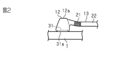
- the measuring instrument 10 has a main body portion 11, a sensor head 12, and a connecting portion 13 for connecting the main body portion 11 and the sensor head 12.
- the measuring device 10 is an oral water content measuring device that measures, for example, the amount of water in the oral cavity as a measurement target.
- the main body 11 is formed in a substantially rectangular parallelepiped shape that is long in the same direction as the longitudinal direction of the measuring instrument 10, and has an upper surface 11a, a lower surface 11b, a pair of side surfaces 11c, and a pair of end surfaces 11d and 11e.
- the end faces 11d and 11e of the main body 11 may be referred to as the tip end and the base end of the main body 11, respectively.
- the portion of the main body 11 that is closer to the end face 11d, more specifically, the portion of the total length of the main body 11 that is closer to the end face 11d than the center of the main body 11 is referred to as the connection portion side or the tip end side portion of the main body portion. There is something to do.
- the portion of the main body 11 that is closer to the end face 11e is the base of the anti-connection portion side or the main body portion. It may be called the end side part.
- a display unit 15 for displaying measurement results and the like is provided on the upper surface 11a of the main body unit 11. Further, a driving battery 16 for driving the measuring instrument 10 is housed inside the main body 11.
- the battery 16 is configured to form a long columnar shape in one direction.
- the battery 16 is provided on the connecting portion 13 side of the main body portion 11.
- the battery 16 has a large mass as a member constituting the measuring instrument 10. Therefore, by setting the battery 16 on the connecting portion 13 side in the main body portion 11, the center of gravity of the measuring instrument 10 is set on the connecting portion 13 side of the main body portion 11.
- the connecting portion 13 projects from one end surface 11d of the main body portion 11.
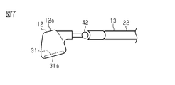
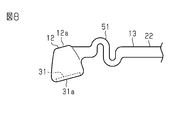
- the connecting portion 13 has a swinging portion 21 and a supporting portion 22.
- the swing portion 21 is formed in a bellows shape, for example.
- the swinging portion 21 is for swinging the sensor head 12 in the pitch direction (vertical direction) with respect to the main body portion 11.
- the swinging portion 21 of the present embodiment can swing the sensor head 12 in the roll direction (rotational direction). Further, the swinging portion 21 can be swung more flexibly by forming the sensor head 12 and the supporting portion 22 in two colors using a soft member.
- the support portion 22 is a portion that connects the main body portion 11 and the swing portion 21.
- the shape is thinner than the main body 11 and the sensor head 12, but the support 22 may be thinner than the main body 11.
- the sensor head 12 has a sensor unit 31.
- the sensor unit 31 is, for example, a capacitance type sensor. As shown in FIG. 3, the sensor unit 31 has a pair of electrodes 32. The pair of electrodes 32 are arranged in a comb-teeth shape. The pair of electrodes 32 function as electrodes of a capacitor. That is, the liquid on the surface of the measurement target T facing the measurement surface 31a of the sensor unit 31 functions as a dielectric for the pair of electrodes 32.
- the capacitance value of the pair of electrodes 32 is a value corresponding to the amount of water on the surface of the measurement target T.
- the measuring instrument 10 has a built-in circuit board on which components such as an oscillation circuit and a control circuit (not shown) are mounted.
- the oscillator circuit outputs a signal with a frequency corresponding to the capacitance value of the sensor unit.
- the control circuit detects the amount of water to be measured by the number of pulses of the output signal of the oscillation circuit.
- the control circuit displays the detected water content on the display unit 15.
- the upper surface 12a as the opposite surface facing the measurement surface 31a and the measurement surface 31a are parallel to each other.
- the measuring instrument 10 is provided with a cover member (not shown) so as to at least cover the measuring surface 31a of the sensor unit 31.
- the cover member is made of a transparent or translucent resin. As a result, the measurement target does not directly touch the sensor unit 31.
- the sensor unit 31 of the present embodiment has the measurement surface 31a with respect to the virtual line L1 parallel to the longitudinal direction of the widest virtual surface 101 in the virtual rectangular parallelepiped 100 that accommodates the main body 11 in the minimum volume.
- the angle ⁇ is set in a predetermined range. Since the virtual line L1 of the present embodiment is parallel to the virtual line L2 passing through the central axis along the longitudinal direction of the battery 16, the angle ⁇ of the measurement surface 31a is virtual passing through the central axis along the longitudinal direction of the battery 16. The angle is the same for the line L2.
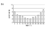
- the present inventor derived the angle ⁇ of the measurement surface 31a of the sensor unit 31 by the following two experiments.
- FIG. 4 shows the experimental results. In FIG. 4, the horizontal axis represents the angle ⁇ and the vertical axis represents the CV value.
- the CV value indicating variation exceeds 5%.
- the CV value can be 5% or less.
- the CV value can be 4% or less.
- FIG. 5 shows the experimental results. In FIG. 5, the horizontal axis represents the angle ⁇ and the vertical axis represents the CV value.
- the CV value exceeds 5%.
- the angle ⁇ is 5 ° or more and 40 ° or less, the CV value can be 5% or less.
- the variation can be reduced by setting the angle ⁇ to 5 ° or more and 38 ° or less. Further, it is more preferable that the angle ⁇ is 10 ° or more and 35 ° or less.
- the amount of water in the oral cavity is measured by pressing the sensor unit 31 against the oral cavity (for example, the tongue) which is the measurement target T while the user holds the main body portion 11.
- the angle ⁇ of the measurement surface 31a is 5 ° or more with respect to the virtual line L1 parallel to the longitudinal direction of the widest virtual surface 101 in the virtual rectangular parallelepiped 100 that accommodates the main body 11 in the minimum volume. It is set to 38 ° or less.
- the tip of the measurement surface 31a comes into contact with the measurement target T in the oral cavity, and the swing portion 21 can be swung around the swing portion 21 with the tip as a fulcrum.
- the tip portion comes into contact with the measurement target T, it is easy to determine the direction in which the load is applied.
- the sensor unit 31 has an angle ⁇ of the measurement surface 31a with respect to the virtual line L1 parallel to the longitudinal direction of the widest virtual surface 101 in the virtual rectangular parallelepiped 100 that accommodates the main body 11 in the minimum volume. Is set to 5 ° or more and 38 ° or less, so that variations in measured values can be suppressed.
- the swinging portion 21 can be flexibly swung by forming the swinging portion 21 in a bellows shape, the measurement surface 31a is uniformly pressed against the oral mucosa, and the angle and the load are constant. It becomes easier to control and can contribute to the improvement of measurement accuracy.
- the measurement surface 31a and the upper surface 12a of the sensor head 12 are parallel to each other, the upper surface 12a of the sensor head 12 is swung when the swing portion 21 is swung to bring the measurement surface 31a into contact with the oral mucosa. It can be understood that the measurement surface 31a is in horizontal contact with the oral mucosa by confirming. Therefore, in the oral cavity, which is difficult to see, the measurement surface 31a is uniformly pressed against the oral mucosa, the angle and the weight are constant, and it becomes easy to control, which can contribute to the improvement of the measurement accuracy.
- the virtual line L1 parallel to the longitudinal direction of the widest virtual surface 101 in the virtual rectangular parallelepiped 100 accommodating the main body 11 in the minimum volume and the central axis along the longitudinal direction of the battery 16.
- a configuration in which the virtual lines L1 and L2 intersect with each other may be adopted.
- the angle ⁇ with respect to the virtual line L1 and the angle ⁇ with respect to the virtual line L2 are different, but one of them may be set to 5 ° or more and 38 ° or less.
- the sensor unit 31 is covered with a cover member, but a configuration in which the cover member is omitted may be adopted.
- the swinging portion 21 is configured to swing in the roll direction (rotational direction), but a configuration in which the swinging portion 21 swings only in the pitch direction (vertical direction) may be adopted.
- the rocking portion 21 is molded in two colors to provide a more flexible configuration, but the present invention is not limited to this.
- the swinging portion may be configured by the spring 41.
- the swinging portion may be formed by the ball joint 42.
- the swinging portion 21 has a bellows shape, but the present invention is not limited to this.
- an S-shaped swinging portion 51 may be adopted.
- a semicircular arch-shaped ( ⁇ -shaped) swinging portion 52 may be adopted.
- a flat arch-shaped swinging portion 53 may be adopted.
- any of the above swinging portions 51 to 53 can swing in the pitch direction when an external force acts on the sensor portion 31 (measurement surface 31a). Further, in the semicircular arch-shaped rocking portion 52 and the flat arch-shaped rocking portion 53, the measurement surface 31a can be brought into close contact with the measurement target T while suppressing interference with the front teeth of the lower jaw.
- connection portion 13 is provided with one swinging portion 21, but a configuration including a plurality of swinging portions may be adopted.
- the measurement surface 31a and the upper surface 12a are parallel to each other, but the measurement surface 31a and the upper surface 12a may not be parallel to each other.
- the center of gravity is set on the connecting portion 13 side of the main body portion 11, but if the center of gravity is set at least in the center of the main body portion 11 in the longitudinal direction, the measurement surface 31a Can be pressed evenly, and the measurement accuracy can be improved.
- a configuration in which the center of gravity is set on the anti-connection portion side of the main body portion 11 may be adopted. According to this configuration, when the measurer holds the main body 11 with his / her hand and uses the measuring instrument 10, the hand holding the main body 11 is less likely to shake, and the angle and weight of the measuring surface 31a with respect to the oral mucosa are controlled. For example, it is advantageous to press the measurement surface 31a against the oral mucosa uniformly and stably.
- the measuring device for measuring the water content in the oral cavity has been described, but the water content may be measured outside the oral cavity.
- the measuring instrument for measuring the water content is used, but other measuring instruments may be used.
- it may be a measuring device such as a pH measuring device or an oral bacteria measuring device. It may also be used as a measuring device for measuring blood flow and blood oxygen. Further, it may be a measuring instrument for measuring a plurality of types of measured values.
- 10 Measuring instrument, 11 ... Main body, 12 ... Sensor head, 12a ... Top surface (opposite surface), 13 ... Connection, 16 ... Battery, 21 ... Swing, 22 ... Support, 31 ... Sensor, 31a ... Measurement surface, 41 ... spring, 42 ... ball joint, 51-53 ... swinging part, 100 ... rectangular parallelepiped, 101 ... virtual surface, L1 ... virtual line, L2 ... virtual line, T ... measurement target, ⁇ ... angle.
Landscapes
- Health & Medical Sciences (AREA)
- Life Sciences & Earth Sciences (AREA)
- General Health & Medical Sciences (AREA)
- Chemical & Material Sciences (AREA)
- Pathology (AREA)
- Physics & Mathematics (AREA)
- Nuclear Medicine, Radiotherapy & Molecular Imaging (AREA)
- Heart & Thoracic Surgery (AREA)
- Analytical Chemistry (AREA)
- General Physics & Mathematics (AREA)
- Immunology (AREA)
- Electrochemistry (AREA)
- Chemical Kinetics & Catalysis (AREA)
- Radiology & Medical Imaging (AREA)
- Biophysics (AREA)
- Engineering & Computer Science (AREA)
- Biomedical Technology (AREA)
- Biochemistry (AREA)
- Medical Informatics (AREA)
- Molecular Biology (AREA)
- Surgery (AREA)
- Animal Behavior & Ethology (AREA)
- Public Health (AREA)
- Veterinary Medicine (AREA)
- Investigating Or Analyzing Materials By The Use Of Electric Means (AREA)
- Measurement And Recording Of Electrical Phenomena And Electrical Characteristics Of The Living Body (AREA)
- Measurement Of The Respiration, Hearing Ability, Form, And Blood Characteristics Of Living Organisms (AREA)
Priority Applications (1)
| Application Number | Priority Date | Filing Date | Title |
|---|---|---|---|
| JP2021526094A JP7279787B2 (ja) | 2019-06-14 | 2020-06-09 | 測定器 |
Applications Claiming Priority (2)
| Application Number | Priority Date | Filing Date | Title |
|---|---|---|---|
| JP2019-111209 | 2019-06-14 | ||
| JP2019111209 | 2019-06-14 |
Publications (1)
| Publication Number | Publication Date |
|---|---|
| WO2020250888A1 true WO2020250888A1 (ja) | 2020-12-17 |
Family
ID=73781208
Family Applications (1)
| Application Number | Title | Priority Date | Filing Date |
|---|---|---|---|
| PCT/JP2020/022686 Ceased WO2020250888A1 (ja) | 2019-06-14 | 2020-06-09 | 測定器 |
Country Status (2)
| Country | Link |
|---|---|
| JP (1) | JP7279787B2 (https=) |
| WO (1) | WO2020250888A1 (https=) |
Citations (3)
| Publication number | Priority date | Publication date | Assignee | Title |
|---|---|---|---|---|
| JP2005205041A (ja) * | 2004-01-23 | 2005-08-04 | Horiba Ltd | 接触式測定器のセンサ部保持構造 |
| JP2006122347A (ja) * | 2004-10-28 | 2006-05-18 | Life:Kk | 口腔水分計 |
| WO2015125222A1 (ja) * | 2014-02-19 | 2015-08-27 | 株式会社らいふ | 口腔内水分測定器 |
-
2020
- 2020-06-09 WO PCT/JP2020/022686 patent/WO2020250888A1/ja not_active Ceased
- 2020-06-09 JP JP2021526094A patent/JP7279787B2/ja active Active
Patent Citations (3)
| Publication number | Priority date | Publication date | Assignee | Title |
|---|---|---|---|---|
| JP2005205041A (ja) * | 2004-01-23 | 2005-08-04 | Horiba Ltd | 接触式測定器のセンサ部保持構造 |
| JP2006122347A (ja) * | 2004-10-28 | 2006-05-18 | Life:Kk | 口腔水分計 |
| WO2015125222A1 (ja) * | 2014-02-19 | 2015-08-27 | 株式会社らいふ | 口腔内水分測定器 |
Also Published As
| Publication number | Publication date |
|---|---|
| JPWO2020250888A1 (https=) | 2020-12-17 |
| JP7279787B2 (ja) | 2023-05-23 |
Similar Documents
| Publication | Publication Date | Title |
|---|---|---|
| US11529093B2 (en) | Intraoral moisture measuring device | |
| JP2022126676A (ja) | 力測定デバイス | |
| US20260096740A1 (en) | Measuring instrument | |
| CN111491563A (zh) | 抓持力测量装置 | |
| JP2005205041A (ja) | 接触式測定器のセンサ部保持構造 | |
| US20100267502A1 (en) | Sports Grip Sensor | |
| US20230277078A1 (en) | Oral pressure measurement device | |
| WO2020250888A1 (ja) | 測定器 | |
| JP2001104256A (ja) | 指先接触圧センサー | |
| US20140276232A1 (en) | Skin tensiometer | |
| JP7124953B2 (ja) | 口腔内測定器 | |
| JP7287452B2 (ja) | 測定器及び口腔内水分測定器 | |
| JP3459939B2 (ja) | 力覚センサ | |
| CN205964016U (zh) | 人体成分测量装置 | |
| JP7622815B2 (ja) | 咬合力計 | |
| ATE303772T1 (de) | Abschätzung der zahnneigung | |
| JP7107396B2 (ja) | カバー | |
| JP4484150B2 (ja) | 体組成計 | |
| JP2014066572A (ja) | 重量測定装置およびロードセル | |
| KR20200001051A (ko) | 교합조정 시에 사용하는 무선 교합력 측정 센서 및 이를 포함하는 무선 교합력 측정 장치 | |
| JP2014066573A (ja) | 重量測定装置および重量測定装置用の荷重伝達部材 | |
| JP3158009U (ja) | 計長器 | |
| KR101756918B1 (ko) | 스푼형 저울 | |
| WO2022088110A1 (zh) | 压力检测装置和电子设备 | |
| TWM288681U (en) | Measurement apparatus |
Legal Events
| Date | Code | Title | Description |
|---|---|---|---|
| 121 | Ep: the epo has been informed by wipo that ep was designated in this application |
Ref document number: 20821879 Country of ref document: EP Kind code of ref document: A1 |
|
| ENP | Entry into the national phase |
Ref document number: 2021526094 Country of ref document: JP Kind code of ref document: A |
|
| NENP | Non-entry into the national phase |
Ref country code: DE |
|
| 122 | Ep: pct application non-entry in european phase |
Ref document number: 20821879 Country of ref document: EP Kind code of ref document: A1 |