WO2020250541A1 - 回転電機 - Google Patents
回転電機 Download PDFInfo
- Publication number
- WO2020250541A1 WO2020250541A1 PCT/JP2020/013867 JP2020013867W WO2020250541A1 WO 2020250541 A1 WO2020250541 A1 WO 2020250541A1 JP 2020013867 W JP2020013867 W JP 2020013867W WO 2020250541 A1 WO2020250541 A1 WO 2020250541A1
- Authority
- WO
- WIPO (PCT)
- Prior art keywords
- heat sink
- heat
- terminal
- circuit board
- grounding
- Prior art date
- Legal status (The legal status is an assumption and is not a legal conclusion. Google has not performed a legal analysis and makes no representation as to the accuracy of the status listed.)
- Ceased
Links
Images


Classifications
-
- H—ELECTRICITY
- H02—GENERATION; CONVERSION OR DISTRIBUTION OF ELECTRIC POWER
- H02K—DYNAMO-ELECTRIC MACHINES
- H02K9/00—Arrangements for cooling or ventilating
- H02K9/22—Arrangements for cooling or ventilating by solid heat conducting material embedded in, or arranged in contact with, the stator or rotor, e.g. heat bridges
-
- H—ELECTRICITY
- H02—GENERATION; CONVERSION OR DISTRIBUTION OF ELECTRIC POWER
- H02K—DYNAMO-ELECTRIC MACHINES
- H02K11/00—Structural association of dynamo-electric machines with electric components or with devices for shielding, monitoring or protection
- H02K11/30—Structural association with control circuits or drive circuits
- H02K11/33—Drive circuits, e.g. power electronics
-
- H—ELECTRICITY
- H02—GENERATION; CONVERSION OR DISTRIBUTION OF ELECTRIC POWER
- H02K—DYNAMO-ELECTRIC MACHINES
- H02K11/00—Structural association of dynamo-electric machines with electric components or with devices for shielding, monitoring or protection
- H02K11/20—Structural association of dynamo-electric machines with electric components or with devices for shielding, monitoring or protection for measuring, monitoring, testing, protecting or switching
- H02K11/21—Devices for sensing speed or position, or actuated thereby
- H02K11/215—Magnetic effect devices, e.g. Hall-effect or magneto-resistive elements
-
- H—ELECTRICITY
- H02—GENERATION; CONVERSION OR DISTRIBUTION OF ELECTRIC POWER
- H02K—DYNAMO-ELECTRIC MACHINES
- H02K5/00—Casings; Enclosures; Supports
- H02K5/04—Casings or enclosures characterised by the shape, form or construction thereof
-
- H—ELECTRICITY
- H02—GENERATION; CONVERSION OR DISTRIBUTION OF ELECTRIC POWER
- H02K—DYNAMO-ELECTRIC MACHINES
- H02K5/00—Casings; Enclosures; Supports
- H02K5/04—Casings or enclosures characterised by the shape, form or construction thereof
- H02K5/22—Auxiliary parts of casings not covered by groups H02K5/06-H02K5/20, e.g. shaped to form connection boxes or terminal boxes
- H02K5/225—Terminal boxes or connection arrangements
-
- H—ELECTRICITY
- H02—GENERATION; CONVERSION OR DISTRIBUTION OF ELECTRIC POWER
- H02K—DYNAMO-ELECTRIC MACHINES
- H02K9/00—Arrangements for cooling or ventilating
- H02K9/22—Arrangements for cooling or ventilating by solid heat conducting material embedded in, or arranged in contact with, the stator or rotor, e.g. heat bridges
- H02K9/223—Heat bridges
-
- H—ELECTRICITY
- H02—GENERATION; CONVERSION OR DISTRIBUTION OF ELECTRIC POWER
- H02K—DYNAMO-ELECTRIC MACHINES
- H02K9/00—Arrangements for cooling or ventilating
- H02K9/22—Arrangements for cooling or ventilating by solid heat conducting material embedded in, or arranged in contact with, the stator or rotor, e.g. heat bridges
- H02K9/227—Heat sinks
-
- H—ELECTRICITY
- H05—ELECTRIC TECHNIQUES NOT OTHERWISE PROVIDED FOR
- H05K—PRINTED CIRCUITS; CASINGS OR CONSTRUCTIONAL DETAILS OF ELECTRIC APPARATUS; MANUFACTURE OF ASSEMBLAGES OF ELECTRICAL COMPONENTS
- H05K7/00—Constructional details common to different types of electric apparatus
- H05K7/20—Modifications to facilitate cooling, ventilating, or heating
-
- H—ELECTRICITY
- H02—GENERATION; CONVERSION OR DISTRIBUTION OF ELECTRIC POWER
- H02K—DYNAMO-ELECTRIC MACHINES
- H02K2211/00—Specific aspects not provided for in the other groups of this subclass relating to measuring or protective devices or electric components
- H02K2211/03—Machines characterised by circuit boards, e.g. pcb
Definitions
- the present invention relates to a rotary electric machine.
- a heat sink is provided at the opening of the housing of the motor, and a circuit board is provided on the side opposite to the motor portion with respect to the heat sink. Further, a heat generating element is mounted on the surface of the circuit board on the heat sink side, and thermal paste is interposed in the gap between the heat generating element and the heat sink. As a result, the heat generated by the heat generating element is transferred to the heat sink via the thermal paste and dissipated from the heat sink.
- a protective film coated with a resist for protecting the circuit board is generally formed on the surface of the circuit board. Therefore, it is necessary to set the gap between the heat generating element and the heat sink to a size that takes into consideration the variation in the thickness dimension of the protective film. As a result, the gap between the heat generating element and the heat sink becomes relatively large, and the efficiency of transferring the heat generated by the heat generating element to the heat sink may decrease.
- An object of the present invention is to provide a rotary electric machine capable of enhancing the heat dissipation effect of a heat sink on a heat generating element in consideration of the above facts.
- a motor portion having a bottomed tubular housing in which one end in the axial direction is closed, an opening of the housing is closed, and a protruding ground contact portion is provided.
- a heat sink having the heat sink, a substrate fixed to the grounded portion, and a non-coated portion in which the portion grounded to the grounded portion is not coated with a resist.
- It is a rotary electric machine including a heat generating element to be generated and a heat transfer member provided between the heat sink and the heat generating element.
- the grounding portion has a first grounding portion extending in the circumferential direction at the outer peripheral portion of the heat sink, and the grounding portion is grounded to the first grounding portion.
- the rotating electric machine is characterized in that a ground pattern is formed in the non-coated portion, and the heat generating element is arranged inside the first grounding portion when viewed from the plate thickness direction of the substrate.
- One or more embodiments of the present invention are characterized in that the length of the first ground contact portion in the longitudinal direction is set to 1 ⁇ 2 or more of the length of the entire circumference of the heat sink in the circumferential direction. It is a rotating electric machine.
- FIG. 5 is an exploded perspective view of the ECU unit shown in FIG. 4 as viewed from below.
- FIG. 5 is an exploded perspective view of the ECU unit shown in FIG. 4 as viewed from above.
- FIG. 5 is an exploded perspective view of the connector shown in FIG. 5 as viewed from below. It is sectional drawing (11-11 line sectional drawing of FIG. 4) which shows the holding state of the connection terminal in the terminal holder in the connector shown in FIG.
- FIG. 6 is a perspective sectional view showing a state in which the positioning pin of the terminal holder in the connector shown in FIG. 4 is fitted in the first positioning hole of the heat sink.
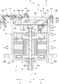
- the rotary electric machine 10 is configured as a rotary electric machine applied to a steering device of a vehicle (automobile). As shown in FIGS. 1 and 2, the rotary electric machine 10 is formed in a substantially columnar shape as a whole. Further, the rotary electric machine 10 includes a motor unit 12 and an ECU unit 14 for controlling the rotation of the motor unit 12. Hereinafter, each configuration of the rotary electric machine 10 will be described.
- one side in the axial direction of the rotary electric machine 10 is the lower side of the rotary electric machine 10, and the other side in the axial direction of the rotary electric machine 10 (FIGS. 1 and 2).
- Arrow B direction side is the upper side of the rotary electric machine 10.
- the direction orthogonal to the vertical direction is defined as the first direction (see arrows C and D in FIGS. 1 and 2) in a plan view viewed from above, and the direction is relative to the first direction.
- the direction orthogonal to each other is the second direction (see arrow E and arrow F in FIG. 1).
- the overhead line that passes through the axis AL of the rotary electric machine 10 and extends in the first direction is set as the first reference line L1 (see FIGS. 4 and 7), and passes through the axis AL of the rotary electric machine 10.
- the overhead line extending in the second direction is the second reference line L2 (see FIGS. 4 and 7).
- the motor unit 12 is configured as a three-phase alternating current brushless motor.
- the motor unit 12 includes a housing 20, a plate holder 24 housed in the housing 20, a rotating shaft 28, a stator 34, a rotor 40, and a bus bar unit 46.
- the housing 20 is formed in a substantially bottomed cylindrical shape that is open to the upper side, and constitutes the outer shell of the rotary electric machine 10.
- a pair of mounting pieces 20A are integrally formed on the outer peripheral portion of the lower end portion of the housing 20.
- the pair of mounting pieces 20A are arranged with the axial direction of the housing 20 as the plate thickness direction, and one side of the housing 20 in the first direction (the side in the direction of arrow C in FIGS. 1 and 2) and the other side in the first direction (FIG. It protrudes in the direction of arrow D in 1 and 2).
- a mounting hole 20A1 is formed through the mounting piece 20A. Then, a fastening member such as a bolt (not shown) is inserted into the mounting hole 20A1, and the housing 20 (that is, the rotary electric machine 10) is fixed to the steering device by the fastening member.
- a plurality of fixing portions 20B (three locations in the present embodiment) extending outward in the radial direction are formed on the outer peripheral portion of the opening end portion of the housing 20. Then, one fixing portion 20B is projected from the housing 20 to one side in the first direction, and three fixing portions 20B are arranged at equal intervals in the circumferential direction of the housing 20.
- a screw portion 20B1 for fixing the heat sink 60 which will be described later, is formed through the fixing portion 20B, and a female screw is formed on the inner peripheral surface of the screw portion 20B1.
- a bottomed cylindrical fixed cylinder portion 20C that is raised downward is integrally formed in the central portion of the bottom wall of the housing 20, and a rotating shaft 28 described later is provided in the fixed cylinder portion 20C.
- a first bearing 22 for supporting is fitted.
- An insertion hole 20C1 for inserting a rotating shaft 28, which will be described later, is formed through the bottom wall of the fixed cylinder portion 20C, and the inside of the first bearing 22 and the outside of the housing 20 are communicated with each other by the insertion hole 20C1. There is.
- the plate holder 24 is formed in a substantially circular plate shape with the vertical direction as the plate thickness direction, and is fitted in the intermediate portion in the vertical direction of the housing 20.
- a second bearing 26 for supporting the rotating shaft 28, which will be described later, is fixed to the central portion of the plate holder 24, and the second bearing 26 and the first bearing 22 are arranged coaxially.
- the rotating shaft 28 is formed in the shape of a round bar extending in the vertical direction, and is arranged coaxially with the housing 20 inside the housing 20.
- the lower end side portion of the rotating shaft 28 is rotatably supported by the first bearing 22, and the upper end side portion of the rotating shaft 28 is rotatably supported by the second bearing 26.
- the upper end of the rotating shaft 28 projects upward with respect to the plate holder 24, and the magnet 30 is fixed to the upper end.
- the lower end of the rotating shaft 28 projects downward with respect to the bottom wall of the housing 20, and a gear 32 connected to the steering device is fixed to the lower end.
- the stator 34 is arranged inside the housing 20 on the lower side of the plate holder 24 and on the outer side in the radial direction of the rotating shaft 28.
- the stator 34 has a stator core 36 made of a magnetic material, and the stator core 36 is formed in a cylindrical shape and is fitted inside the housing 20. Further, a winding 38 corresponding to the U phase, the V phase, and the W phase is wound around the stator core 36.
- the rotor 40 has a rotor core 42, and the rotor core 42 is formed in a cylindrical shape with the vertical direction as the axial direction, and is arranged inside the stator 34 in the radial direction. Then, the rotating shaft 28 is fitted into the shaft core portion of the rotor core 42, and the rotor core 42 (rotor 40) and the rotating shaft 28 are configured to be integrally rotatable. Further, a plurality of magnets 44 (permanent magnets) are fixed in the rotor core 42. As a result, the rotor 40 and the rotating shaft 28 are integrally rotated around the axis AL by passing a current through the U-phase, V-phase, and W-phase windings 38 of the stator 34.
- the bus bar unit 46 is arranged above the stator 34 and is held by the plate holder 24.
- the bus bar unit 46 includes three bus bars 48 corresponding to the U-phase, V-phase, and W-phase windings 38 of the stator 34, and a bus bar holder 50 for holding the bus bar 48.
- one end of the bus bar 48 is connected to the U-phase, V-phase, and W-phase windings 38 of the stator 34.
- the other end of the bus bar 48 is configured as the bus bar terminal portion 48A, and the bus bar terminal portion 48A protrudes upward from the plate holder 24 and is arranged side by side in the second direction.
- the bus bar terminal portion 48A is formed in a substantially long plate shape having a first direction as a plate thickness direction and extending in the vertical direction. Then, the bus bar terminal portion 48A is connected to the connection terminal 86 of the connector 80 described later.
- the ECU unit 14 is assembled to the open end portion of the housing 20 to form the upper end portion of the rotary electric machine 10.
- the ECU unit 14 includes a heat sink 60, a circuit board 70 as a "board” for controlling the motor unit 12, and a connector assembly 90 connected to the circuit board 70.
- the heat sink 60 is made of an aluminum alloy having high thermal conductivity or the like.
- the heat sink 60 is formed in a substantially disk shape with the vertical direction as the plate thickness direction.
- a flange portion 60A extending radially outward is integrally formed on the outer peripheral portion of the upper end portion of the heat sink 60, and the flange portion 60A is formed over the entire circumference of the heat sink 60 in the circumferential direction.
- the heat sink 60 is fitted into the opening of the housing 20 from above, and the flange portion 60A is arranged adjacent to the upper side of the opening end surface of the housing 20.
- the opening of the housing 20 is closed by the heat sink 60. That is, the heat sink 60 is configured as the lid portion of the housing 20, and also constitutes a part of the outer shell of the rotary electric machine 10.
- the flange portion 60A at a position corresponding to the screw portion 20B1 of the housing 20, three first fixing portions 60B protruding outward in the radial direction are integrally formed.
- a fixing hole 60B1 is formed through the first fixing portion 60B. Then, the fixing screw SC1 is inserted into the fixing hole 60B1 from above and screwed into the screw portion 20B1 of the housing 20, so that the heat sink 60 is fixed to the housing 20.
- a pair of second fixing portions 60C extending radially outward are integrally formed on the other side portion of the flange portion 60A in the first direction, and the second fixing portion 60C is the circumference of the heat sink 60. They are arranged side by side in the direction.
- a first fixing screw portion 60C1 for fixing the connector assembly 90, which will be described later, is formed through the second fixing portion 60C, and a female screw is formed on the inner peripheral surface of the first fixing screw portion 60C1. ing.
- a seal groove 60D is formed in the vertical intermediate portion of the outer peripheral portion of the heat sink 60.
- the seal groove 60D is opened to the outside in the radial direction of the heat sink 60 and extends over the entire circumference of the heat sink 60 in the circumferential direction.
- a ring-shaped O-ring OL is housed in the seal groove 60D, and the O-ring OL is made of an elastic member such as rubber.
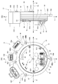
- a first grounding portion 61 as a “grounding portion” for grounding the circuit board 70, which will be described later, is formed on the outer peripheral portion of the lower surface 60E of the heat sink 60.
- the first ground contact portion 61 is formed in a rib shape that protrudes downward from the lower surface 60E of the heat sink 60 and extends along the circumferential direction of the heat sink 60. Further, most of the first grounding portion 61 is formed on the outer peripheral portion of the heat sink 60 on one side in the first direction, and the first grounding portion 61 moves to the other side in the first direction when viewed from below. It is formed in an open substantially C shape (arc shape).
- a step portion 62 which is one step lower than the first ground contact portion 61 is formed on the other side portion in the first direction. Further, both ends in the longitudinal direction of the first ground contact portion 61 are arranged on the other side in the first direction with respect to the second reference line L2 in a bottom view (see FIG. 7). That is, the length of the first grounding portion 61 in the longitudinal direction is set to 1 ⁇ 2 or more of the total length of the heat sink 60 in the circumferential direction (in the present embodiment, the length of the first grounding portion 61 in the longitudinal direction). However, it is set to be approximately 2/3 of the total length of the heat sink 60 in the circumferential direction).
- the step portion 62 is formed in an arc shape that is open to one side in the first direction when viewed from the bottom.
- the first grounding portion 61 includes a first substrate fixing portion 61A, a second substrate fixing portion 61B, and a third substrate fixing portion as three “board fixing portions” protruding inward in the radial direction of the heat sink 60. It has 61C, and the tip surface (lower surface) of the first substrate fixing portion 61A to the third substrate fixing portion 61C is arranged flush with the tip surface (lower surface) of the first ground contact portion 61.
- the first board fixing portion 61A, the second board fixing portion 61B, and the third board fixing portion 61C have a concave first board fixing screw portion 61A1, a second board fixing screw portion 61B1, and a second substrate fixing screw portion 61C that are open downward.
- Each of the three board fixing screw portions 61C1 is formed.
- Female threads are formed on the inner peripheral surfaces of the first substrate fixing screw portion 61A1, the second substrate fixing screw portion 61B1, and the third substrate fixing screw portion 61C1.
- the first substrate fixing portion 61A is formed at the end portion on one side in the longitudinal direction of the first ground contact portion 61, and is formed on one side in the second direction with respect to the first reference line L1 (the side in the direction of arrow E in FIG. 7). Moreover, it is arranged on the other side of the first direction with respect to the second reference line L2.
- the second substrate fixing portion 61B is formed on one side of the first ground contact portion 61 in the longitudinal direction.
- the second substrate fixing portion 61B is arranged on one side in the second direction with respect to the first reference line L1 and on one side in the first direction with respect to the second reference line L2 in a bottom view.
- the third substrate fixing portion 61C is formed on the other side portion in the longitudinal direction of the first ground contact portion 61.
- the third substrate fixing portion 61C is on the other side in the second direction (the side in the arrow F direction in FIG. 7) with respect to the first reference line L1 and in the first direction with respect to the second reference line L2 in the bottom view. It is arranged slightly offset to one side.
- a second grounding portion 63 as a "grounding portion” for grounding and fixing the circuit board 70, which will be described later, is formed on the lower surface 60E of the heat sink 60.
- the second ground contact portion 63 is formed in a substantially cylindrical shape having a relatively low height protruding downward, and the tip surface (lower surface) of the second ground contact portion 63 is the tip surface (lower surface) of the first ground contact portion 61. It is arranged flush with the lower surface).
- a fourth substrate fixing screw portion 63A is formed inside the second grounding portion 63, and a female screw is formed on the inner surface of the fourth substrate fixing screw portion 63A. Further, the second ground contact portion 63 is arranged at a position on the other side in the second direction with respect to the first reference line L1 and on one side in the first direction with respect to the second reference line L2 in a bottom view.
- the portion of the heat sink 60 on one side in the first direction (specifically, the portion on one side in the first direction from a position slightly deviated from the position slightly deviated to the other side in the first direction with respect to the second reference line L2) is the circuit board 70 described later. It is configured as a heat radiating unit 65 for radiating heat generated by the FET 74 of the above.
- the heat radiating portion 65 is formed with a first radiating portion 65A, a second radiating portion 65B, and a third radiating portion 65C protruding downward from the lower surface 60E of the heat sink 60.
- the first heat radiating unit 65A to the third heat radiating unit 65C are formed in a substantially rectangular shape with the first direction as the longitudinal direction in the bottom view.
- the amount of protrusion from the lower surface 60E of the first heat radiating portion 65A to the third heat radiating portion 65C is set to be smaller than the amount of protrusion from the lower surface 60E of the first ground contact portion 61. That is, the lower surfaces of the first heat radiating portion 65A to the third heat radiating portion 65C are arranged above the lower surface of the first grounding portion 61.
- the first heat radiating unit 65A to the third heat radiating unit 65C are arranged side by side with a predetermined interval in the second direction.
- the first heat radiating portion 65A is arranged between the third substrate fixing portion 61C and the second grounding portion 63 in a bottom view.
- the third substrate fixing portion 61C, the first heat radiating portion 65A, and the second grounding portion 63 are arranged side by side in this order on one side in the second direction.
- the second heat radiating portion 65B and the third heat radiating portion 65C are arranged side by side in the second direction at a position between the second substrate fixing portion 61B and the second grounding portion 63 in a bottom view.
- the second grounding portion 63, the second heat radiating portion 65B, the third heat radiating portion 65C, and the second substrate fixing portion 61B are arranged side by side in this order on one side in the second direction.
- a pair of positioning portions 66, 67 for determining the position of the connector 80 of the circuit board 70, which will be described later, are formed on the lower surface 60E of the heat sink 60.
- the positioning portions 66 and 67 project downward from the lower surface 60E of the heat sink 60, and the amount of protrusion of the positioning portions 66 and 67 from the lower surface 60E is compared with the amount of protrusion of the first ground contact portion 61 from the lower surface 60E. It is set small.
- the positioning portions 66 and 67 are arranged on the outer peripheral side of the lower surface 60E of the heat sink 60 on one side in the first direction and adjacent to the inner side in the radial direction of the first ground contact portion 61.
- the pair of positioning portions 66, 67 are arranged at positions symmetrical with respect to the first reference line L1 in the second direction in the bottom view.
- a concave first positioning hole 66A opened downward is formed on the lower surface of the positioning portion 66 on one side in the second direction, and the first positioning hole 66A is formed in a circular shape in a bottom view. ..
- a concave second positioning hole 67A opened downward is formed on the lower surface of the positioning portion 67 on the other side in the second direction, and the second positioning hole 67A is longitudinal in the second direction when viewed from the lower surface. It is formed in a substantially track shape with the direction.
- the width direction (first direction) of the second positioning hole 67A is set to match the diameter of the first positioning hole 66A.
- the lower surface 60E of the heat sink 60 is formed with a recess 60F that is open downward in a portion other than the heat radiating portion 65 (the other side portion in the first direction), and the recess 60F has a substantially hexagonal shape when viewed from the bottom surface. Is formed in.
- the terminal insertion portion 60G is formed in a substantially V shape that is open to one side in the first direction in a bottom view. Further, the terminal insertion portion 60G is arranged on the other side in the first direction with respect to the first ground contact portion 61 and is arranged on the radial inside of the step portion 62 in the bottom view.
- a meat relief 60H opened upward is formed on one side portion in the first direction, and the meat relief 60H is formed in a substantially fan shape in a plan view. Has been done.
- Part 60J is formed on the upper surface of the heat sink 60.
- the second fixing screw portion 60J is formed in a concave shape that is open to the upper side of the heat sink 60, and a female screw is formed on the inner peripheral surface of the second fixing screw portion 60J. Then, the second fixing screw portions 60J at three positions are arranged at predetermined intervals in the second direction in a plan view.
- the circuit board 70 is formed in a disk shape with the vertical direction as the plate thickness direction, and the diameter of the circuit board 70 is set to be slightly smaller than the diameter of the heat sink 60. Has been done.
- the circuit board 70 is arranged coaxially with the heat sink 60 and adjacent to the lower side of the first grounding portion 61 and the second grounding portion 63 of the heat sink 60.
- a gap G1 is formed in the vertical direction between the outer peripheral portion of the circuit board 70 on the other side in the first direction and the stepped portion 62 of the heat sink 60. ..
- four substrate fixing holes 70A are formed through the circuit board 70 at positions corresponding to the first substrate fixing screw portions 61A1 to the fourth substrate fixing screw portion 63A of the heat sink 60.
- the fixing screw SC2 is inserted into the board fixing hole 70A from below and screwed into the first board fixing screw portion 61A1 to the fourth board fixing screw portion 63A, whereby the circuit board 70 is fixed to the heat sink 60.
- the motor unit 12 is arranged on one side (lower side) of the circuit board 70 in the plate thickness direction.
- the portion of the upper surface of the circuit board 70 (the surface facing the heat sink 60 in the vertical direction) that is grounded to the first grounding portion 61 and the second grounding portion 63 of the heat sink 60 is not coated with a resist. It is configured as part 71 (see the part painted in gray in FIG. 8).
- a ground pattern is formed on the non-coated portion 71 of the circuit board 70, and the ground pattern is in contact with the first grounded portion 61 and the second grounded portion 63 of the heat sink 60. That is, the circuit board 70 is grounded to the first grounding portion 61 and the second grounding portion 63 of the heat sink 60.
- the upper surface of the circuit board 70 includes a first area 70AR1 (see the hatched portion in FIG. 8) which is vertically opposed to the heat radiating portion 65 of the heat sink 60, and a recess 60F of the heat sink 60. It is divided into a second area 70AR2 which is arranged so as to face each other in the vertical direction.
- the first area 70AR1 is mainly provided with electronic components of the power supply system in the rotary electric machine 10
- the second area 70AR2 is mainly provided with electronic components of the control system in the rotary electric machine 10.
- FET 74s as a plurality of "heating elements" are provided (mounted) in the first area 70AR1 of the circuit board 70. That is, the plurality of FETs 74 are arranged inside the first ground contact portion 61 in the radial direction in a bottom view. The plurality of FETs 74 are arranged at positions corresponding to the first heat radiating section 65A, the second heat radiating section 65B, and the third heat radiating section 65C of the heat sink 60.
- a pair of FET 74s are arranged at positions corresponding to the first heat radiation unit 65A, the second heat radiation unit 65B, and the third heat radiation unit 65C of the heat sink 60, and the pair of FET 74s are arranged.
- the pair of FET 74s are arranged side by side in the first direction (see FIG. 7).
- a plurality of FETs 74 are arranged on one side in the second direction with respect to the first reference line L1 (a group of four FETs 74 corresponding to the second heat radiation unit 65B and the third heat radiation unit 65C).
- a second group (a group of two FETs 74 corresponding to the first heat radiation unit 65A) arranged on the other side of the second direction with respect to the first reference line L1.
- the second grounding portion 63 of the heat sink 60 is arranged between the first group and the second group of the FET 74. More specifically, the first group of the FET 74 is arranged between the second grounding portion 63 and the second substrate fixing portion 61B, and the second group of the FET 74 is formed by the third substrate fixing portion 61C and the second grounding portion 63. It is placed between.
- a minute gap G2 is formed in the vertical direction between the FET 74 and the first heat radiation unit 65A, the second heat radiation unit 65B, and the third heat radiation unit 65C.
- the amount of protrusion is set from the lower surface 60E of the heat sink 60 of the first heat radiating unit 65A, the second heat radiating unit 65B, and the third heat radiating unit 65C (see FIG. 12).
- a heat-dissipating grease GR (see FIG. 12) as a "heat transfer member" is provided in the gap G2.
- a magnetic sensor 72 is provided (mounted) in the center of the lower surface (one side surface) of the circuit board 70.
- the magnetic sensor 72 is arranged close to the upper side of the magnet 30 on the rotating shaft 28 of the motor unit 12, and the magnetic sensor 72 and the magnet 30 are arranged so as to face each other in the vertical direction (see FIG. 2). As a result, the rotation amount (rotation angle) of the rotation shaft 28 is detected by the magnetic sensor 72.
- a pair of circular substrate-side positioning holes 70B are formed through at positions corresponding to the first positioning holes 66A and the second positioning holes 67A of the heat sink 60.
- the diameter dimension of the substrate side positioning hole 70B is set to be substantially the same as the diameter dimension of the first positioning hole 66A.
- the lower surface of the circuit board 70 has a portion on one side in the first direction (specifically, a position corresponding to the bus bar terminal portion 48A described above).
- a connector 80 for connecting the circuit board 70 and the motor unit 12 (three bus bars 48) is provided.
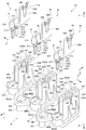
- the connector 80 will be described.
- the connector 80 has three connection terminals 86 and a terminal holder 81 for holding the three connection terminals 86. It is configured to include. Then, the bus bar terminal portion 48A of the bus bar 48 is press-fitted into the connection terminal 86, and the motor portion 12 and the connection terminal 86 are connected. That is, the connector 80 is configured as a so-called press-fit connector.
- the terminal holder 81 is made of a resin material (insulating material).
- the terminal holder 81 is formed in a substantially E-shaped block shape that is open downward when viewed from the first direction.
- the terminal holder 81 includes a base portion 82 that constitutes the base end portion (upper end portion) of the terminal holder 81, and three holding main bodies that protrude downward (motor portion 12 side) from the base portion 82. It is configured to include part 83.
- the base portion 82 is formed in a substantially rectangular plate shape with the vertical direction as the plate thickness direction and the second direction as the longitudinal direction, and is grounded on the lower surface of the circuit board 70. Then, the base portion 82 is arranged with respect to the circuit board 70 so that the central portion in the longitudinal direction of the base portion 82 coincides with the first reference line L1 in the bottom view (see FIG. 4).
- a pair of hole portions 82A are formed through the base portion 82, and the hole portions 82A are arranged at positions symmetrical with respect to the first reference line L1 in the second direction in a bottom view.
- the hole 82A is formed in a substantially track shape with the first direction as the longitudinal direction. Then, the head of the fixing screw SC2 is arranged in the hole 82A on the other side in the second direction.
- the base portion 82 is integrally formed with a pair of positioning pieces 82B extending to one side in the first direction at positions corresponding to the pair of hole portions 82A.
- a positioning pin 82C is formed at the tip of the positioning piece 82B, and the positioning pin 82C is bottomed so as to protrude upward (to the circuit board 70 side) from the positioning piece 82B and open to the lower side. It is formed in a cylindrical shape. Further, the diameter of the positioning pin 82C is set to be substantially the same as the diameter of the substrate-side positioning hole 70B of the circuit board 70 and the first positioning hole 66A of the heat sink 60.
- the positioning pin 82C on one side in the second direction is fitted in the substrate side positioning hole 70B of the circuit board 70 and in the first positioning hole 66A of the heat sink 60 (see FIG. 12). Further, the positioning pin 82C on the other side in the second direction is fitted in the substrate side positioning hole 70B of the circuit board 70 and in the second positioning hole 67A of the heat sink 60. As a result, the position of the terminal holder 81 (that is, the connector 80) with respect to the heat sink 60 is determined by the positioning pin 82C.
- the three holding main body portions 83 are projected downward from both ends in the longitudinal direction and the central portion in the longitudinal direction of the base portion 82, respectively.
- the holding main body portion 83 extends along the width direction (first direction) of the base portion 82 in a bottom view. Further, the holding main body 83 includes a holder portion 84 that constitutes one end in the first direction of the holding main body 83, and a cover portion 85 that constitutes the other end in the first direction of the holding main body 83. It is configured.
- the holder portion 84 is formed in the shape of a substantially rectangular parallelepiped block protruding downward from the base portion 82.
- a pair of holding holes 84A1 and 84A2 are formed in the holder portion 84 at the center portion in the width direction (second direction) of the holding main body portion 83, and the holding holes 84A1 and 84A2 are penetrated in the vertical direction. That is, the holding holes 84A1 and 84A2 also penetrate the base portion 82.
- the holding holes 84A1 and 84A2 are formed in a substantially rectangular shape in a bottom view, and are arranged side by side along the first direction.
- the holding holes 84A2 arranged on the other side in the first direction are arranged at the other end of the holder portion 84 in the first direction, and the holding holes 84A2 are arranged at the other end of the holder portion 84 in the first direction.
- the 84A2 is open to the other side in the first direction in a bottom view.
- the dimensions of the holding holes 84A1 and 84A2 in the second direction are set to be slightly larger than the plate thickness of the connection terminal 86 described later.
- the cover portion 85 is formed in a substantially U-shaped columnar shape open to one side in the first direction when viewed from the bottom, and is formed in a substantially flat shape with the second direction as the thickness direction.
- the cover portion 85 includes a pair of first side walls 85A having a plate thickness direction in the second direction and a second side wall 85B connecting the ends of the pair of first side walls 85A on the other side in the first direction. , Is included.
- the amount of protrusion of the cover portion 85 from the base portion 82 is significantly larger than the amount of protrusion of the holder portion 84 from the base portion 82.
- one end in the first direction at the base end of the pair of first side walls 85A is connected to the holder 84.
- the inside of the cover portion 85 is configured as an accommodating portion 85C for accommodating the connection terminal 86 described later.
- a guide groove 85D is formed at the tip end portion (lower end portion) of the pair of first side wall 85A at the intermediate portion in the first direction.
- the guide groove 85D is formed in a slit shape extending in the vertical direction and is penetrated in the second direction.
- a pair of inclined portions 85E are formed at the opening end of the guide groove 85D, and the inclined portions 85E are separated from each other toward the lower side (opening side of the guide groove 85D) (width direction of the guide groove 85D). It is tilted to the outside).
- the groove width of the guide groove 85D is set to be slightly larger than the plate thickness of the bus bar terminal portion 48A, and in the connected state between the connection terminal 86 and the bus bar terminal portion 48A described later, the bus bar terminal portion 48A is set as the guide groove. It is designed to be inserted in the 85D.
- a pair of guide ribs 85F are formed on the inner peripheral surfaces of the pair of first side walls 85A.
- the guide ribs 85F are arranged on one side and the other side in the first direction with respect to the guide groove 85D, respectively, and extend downward from the base portion 82.
- the guide ribs 85F arranged to face each other in the second direction form a set, and the separation distance of the set guide ribs 85F in the second direction substantially matches the plate thickness of the connection terminal 86 described later. It is set.
- An inclined surface 85G is formed at the tip of the guide rib 85F, and the inclined surface 85G is inclined toward the first side wall 85A as it goes downward.
- a support projection portion 85H (see FIG. 11) is provided at a boundary portion with the holding hole 84A2 arranged on the other side in the first direction of the holder portion 84.
- the support protrusion 85H protrudes downward from the base portion 82, and the amount of protrusion of the support protrusion 85H from the base portion 82 is smaller than the amount of protrusion of the holder portion 84 from the base portion 82. ..
- the support protrusion 85H is formed in a substantially trapezoidal shape in a cross-sectional view seen from the second direction.
- connection terminal 86 As shown in FIGS. 10 and 11, the connection terminal 86 is made of a metal plate material. Further, the connection terminal 86 is arranged with the second direction as the plate thickness direction, and is held by each of the three holding main body portions 83 in the terminal holder 81. The connection terminal 86 is formed in a substantially crank-shaped plate shape when viewed from the second direction. Specifically, the connection terminal 86 includes a terminal fixing portion 87 constituting one end of the connection terminal 86 (one end in the first direction) and the other end of the connection terminal 86 (the other end in the first direction). The terminal connecting portion 88 constituting the portion) and the connecting portion 89 connecting the terminal fixing portion 87 and the terminal connecting portion 88 are included.
- the terminal fixing portion 87 is formed in a substantially inverted U-shaped plate shape that is open to the upper side (circuit board 70 side) when viewed from the second direction.
- the terminal fixing portion 87 is configured to include a base portion 87A forming the lower end portion of the terminal fixing portion 87 and a pair of terminal portions 87B1 and 87B2 extending upward from the base portion 87A. ..
- the base portion 87A is formed in a substantially rectangular plate shape, and is arranged adjacent to the lower side of the holder portion 84 of the terminal holder 81.
- the pair of terminal portions 87B1 and 87B2 are arranged side by side in the first direction corresponding to the pair of holding holes 84A1 and 84A2 in the holder portion 84 of the terminal holder 81.
- a plurality of (four locations in the present embodiment) protrusions 87C are integrally formed.
- the two protruding portions 87C are projected from the base end portion of the terminal portion 87B1 to one side in the first direction and are arranged side by side in the vertical direction.
- the other two protruding portions 87C are projected from the base end portion of the terminal portion 87B1 to the other side in the first direction, and are arranged side by side in the vertical direction.
- the protrusion 87C is formed in a substantially wedge shape when viewed from the second direction.
- the terminal portion 87B1 is fitted into the holding hole 84A1 from below so that the protrusion 87C bites into the inner peripheral surface of the holding hole 84A1 of the terminal holder 81.
- the terminal portion 87B1 (that is, the connection terminal 86) is held by the terminal holder 81.
- a plurality of (two places in the present embodiment) protrusions 87C are integrally formed on the base end side of the terminal portion 87B2 arranged on the other side in the first direction, and the protrusions 87C are formed. , It protrudes from the terminal portion 87B2 to one side in the first direction and the other side in the second direction. Then, the terminal portion 87B2 is fitted into the holding hole 84A2 from below so that the protrusion 87C bites into the inner peripheral surface of the holding hole 84A2 of the terminal holder 81. As a result, the terminal portion 87B2 (that is, the connection terminal 86) is held by the terminal holder 81.
- projecting portions 87D (see FIG. 10) projecting to one side in the second direction are formed on the portions on the base end side of the terminal portions 87B1 and 87B2, respectively, and the protruding portions 87D are formed by half-cutting or the like. It is molded. Then, the terminal portions 87B1, 87B2 are fitted into the holding holes 84A1, 84A2 in a state where the protruding portion 87D is in pressure contact with the inner peripheral surfaces of the holding holes 84A1, 84A2 of the terminal holder 81.
- the tip portions (upper end portions) of the pair of terminal portions 87B1 and 87B2 project upward from the terminal holder 81 (on the circuit board 70 side), are inserted into the terminal holes 70C of the circuit board 70, and are inserted into the circuit board 70. It is fixed by soldering (see FIG. 11). In FIG. 11, for convenience, the solder for fixing the pair of terminal portions 87B1 and 87B2 and the circuit board 70 is not shown.
- the terminal connection portion 88 is formed in a substantially U-shaped plate shape that is open to the lower side (motor portion 12 side) when viewed from the second direction. That is, the terminal connection portion 88 is formed with a press-fitting groove 88A that is open downward.
- the groove width on the opening side of the press-fitting groove 88A is set to be larger than the groove width of the guide groove 85D of the terminal holder 81.
- the groove width on the bottom side of the press-fit groove 88A is set to become smaller toward the bottom of the press-fit groove 88A.
- a terminal press-fitting portion 88B is formed at the open end of the press-fitting groove 88A.
- the terminal press-fitting portion 88B is bent to one side in the second direction, and is formed in a substantially semicircular shape that is convex inward in the groove width direction of the press-fitting groove 88A when viewed from the second direction.
- the distance between the pair of terminal press-fitting portions 88B in the first direction is set to be slightly shorter than the plate thickness of the bus bar terminal portion 48A.
- the terminal connection portion 88 is housed in the accommodating portion 85C of the terminal holder 81, and the entire terminal connection portion 88 is covered by the cover portion 85 of the terminal holder 81.
- the lower end of the terminal connection portion 88 is arranged above the inclined portion 85E of the terminal holder 81, and the guide groove of the terminal holder 81 is arranged in the first direction.
- the 85D and the press-fitting groove 88A of the terminal connecting portion 88 are arranged at the same positions.
- a part (arc-shaped top) of the pair of terminal press-fitting portions 88B is arranged at a position above the inclined portion 85E of the terminal holder 81, and the guide groove 85D It is arranged so as to protrude inward in the groove width direction of.
- the bus bar terminal portion 48A of the bus bar 48 is press-fitted between the pair of terminal press-fitting portions 88B, and the terminal press-fitting portion 88B is press-fitted to the bus bar terminal portion 48A.
- the terminal connection portion 88 is sandwiched in the second direction by the guide rib 85F of the terminal holder 81, and is separated downward from the base portion 82 (that is, the circuit board 70) of the terminal holder 81. It is arranged. That is, a gap is formed between the terminal connection portion 88 and the base portion 82, and the terminal connection portion 88 is held by the terminal holder 81 so as to be relatively displaceable in the vertical direction.
- the connecting portion 89 is formed in a substantially rectangular plate shape with the second direction as the plate thickness direction, and connects the base end portion of the other terminal portion 87B2 of the terminal fixing portion 87 and the upper end portion of the terminal connecting portion 88.
- the connection terminal 86 is formed in a flat plate shape having no bent portion, except for the terminal press-fitting portion 88B in the terminal connection portion 88.
- the connecting portion 89 is arranged on the upper side (circuit board 70 side) of the press-fitting groove 88A, and is accommodated in the accommodating portion 85C of the terminal holder 81. That is, the connecting portion 89 and the press-fitting groove 88A are arranged so as to be offset in the vertical direction.
- the portion of the connecting portion 89 on the terminal fixing portion 87 side is arranged adjacent to the support protrusion 85H of the terminal holder 81 on the lower side and is in contact with the support protrusion 85H.
- the support protrusion 85H supports the portion of the connecting portion 89 on the terminal fixing portion 87 side from the circuit board 70 side.
- the connecting portion 89 bends and deforms from the contact portion with the support projection portion 85H, and the terminal connecting portion 88 moves toward the circuit board 70 side. It is configured to be displaced.
- the connector assembly 90 has a mold portion 91, and the mold portion 91 is made of a resin material (insulating material).
- the mold portion 91 includes a mold base 92, three first connector portions 93A, a second connector portion 93B, and a third connector portion 93C.
- the mold base 92 is formed in a plate shape with the vertical direction as the plate thickness direction. Then, the mold base 92 is arranged adjacent to the upper side of the portion of the heat sink 60 on the other side in the first direction, and closes the terminal insertion portion 60G of the heat sink 60. In other words, the heat radiating portion 65 (the portion on one side in the first direction) of the heat sink 60 is not covered by the mold base 92 (mold portion 91) and is exposed to the outside of the rotary electric machine 10.
- Five fixing holes 92A are formed through the mold base 92 at positions corresponding to the first fixing screw portion 60C1 and the second fixing screw portion 60J of the heat sink 60. Then, the fixing screw SC3 is inserted into the fixing hole 92A and screwed into the first fixing screw portion 60C1 and the second fixing screw portion 60J, so that the mold base 92 (that is, the connector assembly 90) is attached to the heat sink 60. It is fixed.
- the first connector portion 93A, the second connector portion 93B, and the third connector portion 93C are each formed in a tubular shape, and extend downward from the other end of the mold base 92 in the first direction. Further, the first connector portion 93A, the second connector portion 93B, and the third connector portion 93C are arranged on the outer side in the radial direction of the upper end portion of the housing 20, and are arranged side by side in the circumferential direction of the housing 20. That is, the first connector portion 93A to the third connector portion 93C are formed in a tubular shape that is open downward.
- the mold base 92 is arranged with respect to the circuit board 70 so that the mold base 92 (connector assembly 90) and the FET 74 of the circuit board 70 do not wrap in a plan view (see FIG. 8).
- the heat radiating portion 65 of the heat sink 60 is not covered by the mold base 92 (mold portion 91) and is exposed to the outside of the rotary electric machine 10 (see FIG. 1).
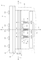
- the connector assembly 90 has a plurality of terminals 94 for connecting the circuit board 70 and the control unit of the vehicle, and the terminal 94 is integrally formed with the mold portion 91. Specifically, the intermediate portion in the longitudinal direction of the terminal 94 is inserted into the terminal insertion portion 60G of the heat sink 60, and one end of the terminal 94 is soldered to the circuit board 70. As a result, the soldered state of one end of the terminal 94 to the circuit board 70 can be visually recognized from the gap G1 between the step portion 62 of the heat sink 60 and the circuit board 70 (FIG. 4B). )reference).
- the other end of the terminal 94 is arranged inside the first connector portion 93A, the second connector portion 93B, and the third connector portion 93C, respectively. Then, the external connector on the vehicle side is connected to the first connector portion 93A to the third connector portion 93C. As a result, a current is supplied to the circuit board 70 from the vehicle side, a control signal is output, and the motor unit 12 is driven by the control of the circuit board 70.
- the circuit board 70 is arranged adjacent to the lower side of the heat sink 60, and the first grounding portion 61 protruding downward and the lower surface 60E of the heat sink 60 A second ground contact portion 63 is formed. Then, the circuit board 70 is grounded to the tip surface of the first grounding portion 61 of the heat sink 60 and the tip surface of the second grounding portion 63, and is fixed to the heat sink 60 by the fixing screw SC2. Further, a plurality of FETs 74 are mounted on the upper surface of the circuit board 70, and the FETs 74 are arranged close to the first heat radiation portion 65A, the second heat radiation portion 65B, and the third heat radiation portion 65C of the heat sink 60. There is.
- a minute gap G2 is formed between the FET 74 and the first heat radiation unit 65A, the second heat radiation unit 65B, and the third heat radiation unit 65C, and the gap G2 is for heat dissipation.
- Grease GR is intervening. Therefore, the heat generated by the FET 74 is transferred to the heat sink 60 from the first heat radiating section 65A, the second heat radiating section 65B, and the third heat radiating section 65C via the heat radiating grease GR. Then, the heat transferred to the heat sink 60 is radiated from the heat radiating unit 65 to the outside of the rotary electric machine 10.
- the portion of the circuit board 70 that is grounded to the first grounded portion 61 and the second grounded portion 63 of the heat sink 60 is configured as a non-coated portion 71, and the non-coated portion 71 is coated with a resist. Absent. Therefore, the circuit board 70 can be grounded to the first grounding portion 61 and the second grounding portion 63 of the heat sink 60 without being affected by the variation in the film thickness of the resist. As a result, the gap G2 between the FET 74 mounted on the circuit board 70 and the first heat dissipation portion 65A, the second heat dissipation portion 65B, and the third heat dissipation portion 65C of the heat sink 60 can be set as small as possible. ..
- the gap G2 can be set smaller than that of the comparative example in which the non-coated portion 71 of the circuit board 70 is coated with the resist, and the first heat radiating portion 65A, the second heat radiating portion 65B, and the third heat radiating portion 65B can be set.
- the FET 74 can be arranged at a position closer to the heat radiating portion 65C. As a result, the heat conduction path in the heat-dissipating grease GR can be shortened. Therefore, as compared with the above comparative example, the heat generated by the FET 74 can be efficiently transferred to the heat sink 60. As described above, the heat dissipation effect of the heat sink 60 on the FET 74 can be enhanced.
- a ground pattern is formed on the non-coated portion 71 of the circuit board 70. Therefore, the circuit board 70 is grounded to the first grounding portion 61 of the heat sink 60. Further, the first ground contact portion 61 is formed on the outer peripheral portion of the heat sink 60 and is formed in a substantially arc shape extending in the circumferential direction.
- the FET 74 of the circuit board 70 is arranged inside the first grounding portion 61 of the heat sink 60 in the radial direction in a bottom view. Therefore, the arrangement configuration can be such that the FET 74 is surrounded by the first grounding portion 61.
- the first grounding portion 61 functions as a shielding portion that shields electrical noise from the FET 74. As a result, for example, radiation noise from the FET 74 can be reduced. Therefore, the reliability of the rotary electric machine 10 can be improved.
- the length of the first ground contact portion 61 of the heat sink 60 in the longitudinal direction is set to 1/2 or more of the length of the entire circumference of the heat sink 60 in the circumferential direction. Therefore, the FET 74 can surround more than half of the circuit board 70. Therefore, the shielding effect of the first grounding portion 61 on the electronic components mounted on the circuit board 70 including the FET 74 can be enhanced.
- a step portion 62 that is one step lower than the tip surface (lower surface) of the first ground contact portion 61 is formed, and the step portion 62 is formed.
- the step portion 62 is formed.
- a gap G1 is formed between the step portion 62 and the circuit board 70.
- a terminal insertion portion 60G through which the terminal 94 of the connector assembly 90 is inserted is arranged inside the step portion 62 in the radial direction.
- the terminal 94 of the connector assembly 90 is configured to be visible from the gap G1 between the step portion 62 and the circuit board 70. Therefore, when the connector assembly 90 is assembled to the heat sink 60, the soldered state between the terminal 94 and the circuit board 70 can be confirmed from the gap G1. Therefore, workability when assembling the connector assembly 90 to the heat sink 60 can be improved.
- the second grounding portion 63 is arranged between the first heat radiating portion 65A and the second heat radiating portion 65B in a bottom view. Therefore, in the ECU unit 14, the second grounding portion 63 is arranged between the first group of the FET 74 and the second group of the FET 74 in a bottom view. Then, the circuit board 70 is fixed to the second grounding portion 63 by the fixing screw SC2. Thereby, for example, even when the circuit board 70 warps in the direction away from the heat sink 60, the warp of the circuit board 70 can be corrected and the circuit board 70 can be fixed to the heat sink 60.
- the first group of the FET 74 is arranged between the second grounding portion 63 and the second substrate fixing portion 61B, and the second group of the FET 74 is arranged between the third substrate fixing portion 61C and the second grounding portion 61B. It is arranged between the unit 63 and the unit 63. That is, the circuit board 70 is fixed to the heat sink 60 at the portions on both sides in the second direction with respect to the first group of the FET 74, and is fixed to the heat sink 60 at the portions on both sides in the second direction with respect to the second group of the FET 74. ing.
- the gap G2 between the FET 74 and the first heat radiation section 65A, the second heat dissipation section 65B, and the third heat dissipation section 65C of the heat sink 60 can be further stabilized. Therefore, it is possible to effectively stabilize the heat dissipation effect of the heat sink 60 with respect to the FET 74.
- the upper surface of the circuit board 70 is divided into a first area 70AR1 and a second area 70AR2.
- the first area 70AR1 is mainly provided with electronic components of the power supply system in the rotary electric machine 10, and the second area 70AR2.
- the heat sink 60 is formed with a recess 60F opened to the side of the second area 70AR2 at a portion facing the second area 70AR2 in the vertical direction. Therefore, in the circuit board 70, electronic components of the control system having a relatively high height can be arranged in the second area 70AR2.
- the outer peripheral portion of the lower surface 60E of the heat sink 60 is composed of the first grounding portion 61 and the step portion 62, but the outer peripheral portion of the lower surface 60E of the heat sink 60 is formed only by the first grounding portion 61. It may be configured by. That is, the entire outer peripheral portion of the circuit board 70 may be grounded to the first grounding portion 61. In this case, the sealing effect of the first grounding portion 61 on electronic components such as the FET 74 can be further enhanced.
- the length of the first grounding portion 61 of the heat sink 60 in the longitudinal direction is set to 1/2 or more of the length of the entire circumference of the heat sink 60 in the circumferential direction, but the first grounding is performed.
- the length of the portion 61 in the longitudinal direction may be set to less than 1/2 of the length of the entire circumference of the heat sink 60 in the circumferential direction.
- the clearance between the heat generating element and the heat sink can be set without considering the variation in the coating thickness of the resist, so that heat transfer can be performed.
- the heat conduction path of the member can be shortened, and the heat dissipation effect of the heat sink on the heat generating element can be enhanced.
- Rotating electric machine 12
- Motor part 20 Housing 60
- Heat sink 61 First grounding part (grounding part)
- Circuit board (board) 71
- Non-coated part GR Heat dissipation grease (heat transfer member)
Landscapes
- Engineering & Computer Science (AREA)
- Power Engineering (AREA)
- Microelectronics & Electronic Packaging (AREA)
- Physics & Mathematics (AREA)
- Thermal Sciences (AREA)
- Cooling Or The Like Of Electrical Apparatus (AREA)
- Power Steering Mechanism (AREA)
Priority Applications (2)
| Application Number | Priority Date | Filing Date | Title |
|---|---|---|---|
| US17/615,731 US12003168B2 (en) | 2019-06-14 | 2020-03-26 | Rotary electric machine |
| CN202080038931.4A CN113875133B (zh) | 2019-06-14 | 2020-03-26 | 旋转电机 |
Applications Claiming Priority (2)
| Application Number | Priority Date | Filing Date | Title |
|---|---|---|---|
| JP2019-110748 | 2019-06-14 | ||
| JP2019110748A JP7023892B2 (ja) | 2019-06-14 | 2019-06-14 | 回転電機 |
Publications (1)
| Publication Number | Publication Date |
|---|---|
| WO2020250541A1 true WO2020250541A1 (ja) | 2020-12-17 |
Family
ID=73781935
Family Applications (1)
| Application Number | Title | Priority Date | Filing Date |
|---|---|---|---|
| PCT/JP2020/013867 Ceased WO2020250541A1 (ja) | 2019-06-14 | 2020-03-26 | 回転電機 |
Country Status (4)
| Country | Link |
|---|---|
| US (1) | US12003168B2 (https=) |
| JP (1) | JP7023892B2 (https=) |
| CN (1) | CN113875133B (https=) |
| WO (1) | WO2020250541A1 (https=) |
Families Citing this family (3)
| Publication number | Priority date | Publication date | Assignee | Title |
|---|---|---|---|---|
| EP4379966A4 (en) * | 2021-07-28 | 2024-09-04 | Mitsubishi Electric Corporation | CIRCUIT CONNECTION DEVICE, DYNAMOELECTRIC MACHINE DEVICE, AND METHOD FOR MANUFACTURING CIRCUIT CONNECTION DEVICE |
| US20240066995A1 (en) * | 2022-08-23 | 2024-02-29 | Black & Decker Inc. | Motor control panel for electric lawn apparatus |
| WO2025262769A1 (ja) * | 2024-06-18 | 2025-12-26 | 三菱電機モビリティ株式会社 | 回転電機、および車両 |
Citations (2)
| Publication number | Priority date | Publication date | Assignee | Title |
|---|---|---|---|---|
| JP2017184542A (ja) * | 2016-03-31 | 2017-10-05 | 日本電産株式会社 | モータ |
| JP2018148688A (ja) * | 2017-03-06 | 2018-09-20 | 株式会社デンソー | 駆動装置 |
Family Cites Families (2)
| Publication number | Priority date | Publication date | Assignee | Title |
|---|---|---|---|---|
| US7199496B2 (en) * | 2005-01-18 | 2007-04-03 | Oriental Motor Boston Technology Group Incorporated | Integrated electric motor and drive, optimized for high-temperature operation |
| JP6514135B2 (ja) * | 2016-03-09 | 2019-05-15 | 日立オートモティブシステムズ株式会社 | 電動駆動装置及び電動パワーステアリング装置 |
-
2019
- 2019-06-14 JP JP2019110748A patent/JP7023892B2/ja active Active
-
2020
- 2020-03-26 CN CN202080038931.4A patent/CN113875133B/zh active Active
- 2020-03-26 WO PCT/JP2020/013867 patent/WO2020250541A1/ja not_active Ceased
- 2020-03-26 US US17/615,731 patent/US12003168B2/en active Active
Patent Citations (2)
| Publication number | Priority date | Publication date | Assignee | Title |
|---|---|---|---|---|
| JP2017184542A (ja) * | 2016-03-31 | 2017-10-05 | 日本電産株式会社 | モータ |
| JP2018148688A (ja) * | 2017-03-06 | 2018-09-20 | 株式会社デンソー | 駆動装置 |
Also Published As
| Publication number | Publication date |
|---|---|
| JP7023892B2 (ja) | 2022-02-22 |
| US12003168B2 (en) | 2024-06-04 |
| CN113875133A (zh) | 2021-12-31 |
| JP2020205654A (ja) | 2020-12-24 |
| CN113875133B (zh) | 2024-03-12 |
| US20220247275A1 (en) | 2022-08-04 |
Similar Documents
| Publication | Publication Date | Title |
|---|---|---|
| JP6997740B2 (ja) | 回転電機及び回転電機の製造方法 | |
| WO2020241027A1 (ja) | 回転電機 | |
| CN101043160B (zh) | 电动动力转向装置用电机 | |
| US10008909B2 (en) | Motor driving control device for vehicle | |
| JP7023892B2 (ja) | 回転電機 | |
| JPWO2018179833A1 (ja) | モータ | |
| JP2023080237A (ja) | 回転電機 | |
| WO2018179831A1 (ja) | モータ | |
| US10958124B2 (en) | Motor | |
| CN112564425A (zh) | 马达以及马达的组装方法 | |
| US20190305651A1 (en) | Motor | |
| JP7231398B2 (ja) | 回転電機 | |
| JP7395924B2 (ja) | モータ装置 | |
| WO2023276678A1 (ja) | 駆動装置 | |
| JP7725916B2 (ja) | 電動機 | |
| JP7809000B2 (ja) | 回転電機 | |
| WO2025018229A1 (ja) | 駆動装置 | |
| WO2023007599A1 (ja) | 回路接続装置、回転電機装置、及び回路接続装置の製造方法 | |
| JP2023135209A (ja) | モータ及びファン装置 | |
| WO2021024546A1 (ja) | 回路基板 |
Legal Events
| Date | Code | Title | Description |
|---|---|---|---|
| 121 | Ep: the epo has been informed by wipo that ep was designated in this application |
Ref document number: 20823585 Country of ref document: EP Kind code of ref document: A1 |
|
| NENP | Non-entry into the national phase |
Ref country code: DE |
|
| 122 | Ep: pct application non-entry in european phase |
Ref document number: 20823585 Country of ref document: EP Kind code of ref document: A1 |