WO2020246346A1 - 撮像装置及びその制御方法、プログラム、記憶媒体 - Google Patents
撮像装置及びその制御方法、プログラム、記憶媒体 Download PDFInfo
- Publication number
- WO2020246346A1 WO2020246346A1 PCT/JP2020/020992 JP2020020992W WO2020246346A1 WO 2020246346 A1 WO2020246346 A1 WO 2020246346A1 JP 2020020992 W JP2020020992 W JP 2020020992W WO 2020246346 A1 WO2020246346 A1 WO 2020246346A1
- Authority
- WO
- WIPO (PCT)
- Prior art keywords
- focus
- lens
- optical system
- evaluation value
- focus detection
- Prior art date
- Legal status (The legal status is an assumption and is not a legal conclusion. Google has not performed a legal analysis and makes no representation as to the accuracy of the status listed.)
- Ceased
Links
Images







Classifications
-
- G—PHYSICS
- G02—OPTICS
- G02B—OPTICAL ELEMENTS, SYSTEMS OR APPARATUS
- G02B7/00—Mountings, adjusting means, or light-tight connections, for optical elements
- G02B7/28—Systems for automatic generation of focusing signals
- G02B7/36—Systems for automatic generation of focusing signals using image sharpness techniques, e.g. image processing techniques for generating autofocus signals
- G02B7/365—Systems for automatic generation of focusing signals using image sharpness techniques, e.g. image processing techniques for generating autofocus signals by analysis of the spatial frequency components of the image
-
- H—ELECTRICITY
- H04—ELECTRIC COMMUNICATION TECHNIQUE
- H04N—PICTORIAL COMMUNICATION, e.g. TELEVISION
- H04N23/00—Cameras or camera modules comprising electronic image sensors; Control thereof
- H04N23/60—Control of cameras or camera modules
- H04N23/67—Focus control based on electronic image sensor signals
-
- G—PHYSICS
- G02—OPTICS
- G02B—OPTICAL ELEMENTS, SYSTEMS OR APPARATUS
- G02B7/00—Mountings, adjusting means, or light-tight connections, for optical elements
- G02B7/02—Mountings, adjusting means, or light-tight connections, for optical elements for lenses
- G02B7/04—Mountings, adjusting means, or light-tight connections, for optical elements for lenses with mechanism for focusing or varying magnification
- G02B7/09—Mountings, adjusting means, or light-tight connections, for optical elements for lenses with mechanism for focusing or varying magnification adapted for automatic focusing or varying magnification
-
- G—PHYSICS
- G03—PHOTOGRAPHY; CINEMATOGRAPHY; ANALOGOUS TECHNIQUES USING WAVES OTHER THAN OPTICAL WAVES; ELECTROGRAPHY; HOLOGRAPHY
- G03B—APPARATUS OR ARRANGEMENTS FOR TAKING PHOTOGRAPHS OR FOR PROJECTING OR VIEWING THEM; APPARATUS OR ARRANGEMENTS EMPLOYING ANALOGOUS TECHNIQUES USING WAVES OTHER THAN OPTICAL WAVES; ACCESSORIES THEREFOR
- G03B13/00—Viewfinders; Focusing aids for cameras; Means for focusing for cameras; Autofocus systems for cameras
- G03B13/32—Means for focusing
- G03B13/34—Power focusing
- G03B13/36—Autofocus systems
-
- G—PHYSICS
- G03—PHOTOGRAPHY; CINEMATOGRAPHY; ANALOGOUS TECHNIQUES USING WAVES OTHER THAN OPTICAL WAVES; ELECTROGRAPHY; HOLOGRAPHY
- G03B—APPARATUS OR ARRANGEMENTS FOR TAKING PHOTOGRAPHS OR FOR PROJECTING OR VIEWING THEM; APPARATUS OR ARRANGEMENTS EMPLOYING ANALOGOUS TECHNIQUES USING WAVES OTHER THAN OPTICAL WAVES; ACCESSORIES THEREFOR
- G03B19/00—Cameras
- G03B19/02—Still-picture cameras
-
- H—ELECTRICITY
- H04—ELECTRIC COMMUNICATION TECHNIQUE
- H04N—PICTORIAL COMMUNICATION, e.g. TELEVISION
- H04N23/00—Cameras or camera modules comprising electronic image sensors; Control thereof
- H04N23/50—Constructional details
- H04N23/55—Optical parts specially adapted for electronic image sensors; Mounting thereof
-
- H—ELECTRICITY
- H04—ELECTRIC COMMUNICATION TECHNIQUE
- H04N—PICTORIAL COMMUNICATION, e.g. TELEVISION
- H04N23/00—Cameras or camera modules comprising electronic image sensors; Control thereof
- H04N23/60—Control of cameras or camera modules
- H04N23/67—Focus control based on electronic image sensor signals
- H04N23/673—Focus control based on electronic image sensor signals based on contrast or high frequency components of image signals, e.g. hill climbing method
-
- H—ELECTRICITY
- H04—ELECTRIC COMMUNICATION TECHNIQUE
- H04N—PICTORIAL COMMUNICATION, e.g. TELEVISION
- H04N23/00—Cameras or camera modules comprising electronic image sensors; Control thereof
- H04N23/70—Circuitry for compensating brightness variation in the scene
- H04N23/75—Circuitry for compensating brightness variation in the scene by influencing optical camera components
Definitions
- the present invention relates to a focus detection technique in an imaging device.
- Patent Document 1 An optical system in which a reflection mirror is arranged on the same optical axis has been proposed as a photographic lens that is compact and realizes a long focal length (see Patent Document 1).
- the photographing optical system disclosed in Patent Document 1 by reflecting light on the inner surface using a reflecting mirror, it is possible to obtain a long focal length and perform high-magnification imaging while having a small outer shape. Realizes the lens.
- Patent Document 1 has the following problems.
- MTF Modulation Transfer Function
- OTF optical Transfer Function
- MTF Modulation Transfer Function
- the present invention has been made in view of the above-mentioned problems, and improves the accuracy of focus detection in an imaging device using a photographing lens having a reflective optical system.
- the imaging apparatus captures the subject image while performing a scanning operation of moving the image pickup element for capturing the subject image and the focus lens included in the photographing optical system along the optical axis of the photographing optical system.
- a focus detection means that calculates a focus evaluation value indicating the degree of focus of a subject based on an image signal obtained by photoelectric conversion by an element and detects the position of a focus lens that maximizes the focus evaluation value.
- the focal point detecting means is a method of calculating the focus evaluation value based on information on the shape of the reflected optical system when the photographing optical system includes a reflected optical system in which a part of a light beam is shielded. Alternatively, it is characterized in that a control method of the focus lens in the scanning operation is set.
- the accompanying drawings are included in the specification and are used to form a part thereof, show embodiments of the present invention, and explain the principles of the present invention together with the description thereof.
- the block diagram of the catadioptric system. The figure explaining the pupil function.
- the figure explaining MTF The figure explaining MTF.
- the figure explaining MTF The figure explaining the correspondence between the diameter of a reflective optical system and an F value.
- a flowchart illustrating the focus detection motion The figure explaining the focus detection area.
- the figure explaining the focus detection evaluation value The figure explaining the change of the focus detection evaluation value by the focus detection band.
- the figure explaining the frequency band of a digital filter The figure explaining the correspondence of MTF and a digital filter.
- the figure explaining the focus detection evaluation value in various MTFs and a focus detection band The figure explaining the setting of the focus detection frequency.
- FIG. 1A and 1B are diagrams showing the configuration of an interchangeable lens digital camera system 200 according to an embodiment of the image pickup apparatus of the present invention.
- the digital camera system 200 includes a camera body 100 and, for example, a photographing lens 500 and a photographing lens 600 which are interchangeably attached to the camera body 100.
- FIG. 1A shows a state in which a photographing lens 600 having a catadioptric system is attached to the camera body 100
- FIG. 1B shows a normal (not having a catadioptric system) photographing lens 500 attached to the camera body 100. It shows the state.
- the photographic lens 500 and the photographic lens 600 have different lens types and are interchangeably attached to the camera body 100.
- the luminous flux transmitted through each lens group in the photographing lens 500 (or 600) is guided to the image sensor 101 that receives the subject image and performs photoelectric conversion.
- the image pickup device 101 is configured to include pixel portions arranged in a matrix for converting a subject image into an electric signal.
- the pixel signal obtained by converting the subject image into an electric signal by the image sensor 101 is subjected to various correction processes for obtaining an image signal and a focus detection signal in the camera CPU 104, and to a live view image, a recorded image, and an EVF image. Processing for conversion is performed. In the present embodiment, these processes and the like are performed by the camera CPU 104, but these processes and the like may be performed by providing a dedicated circuit.
- the operation member 105 is various members for setting the shooting mode and shooting conditions (F value, ISO sensitivity, exposure time, etc.) of the camera.
- the storage medium 106 is a flash memory and is a medium for recording captured still images and moving images.
- the display in the viewfinder 107 includes a small and high-definition display 109 such as an organic EL display and a liquid crystal display, and an eyepiece lens 108.
- the external display 110 comprises an organic EL display or a liquid crystal display having a screen size suitable for naked eye viewing.
- Various information such as the setting state of the camera body 100, the live view image, and the captured image are displayed on the display in the viewfinder 107 and the external display 110.
- the focal plane shutter 111 is arranged in front of the image sensor 101.
- the shutter drive unit 112 is, for example, a motor, and controls the exposure time when capturing a still image by driving and controlling the blades of the shutter.
- the camera-side communication terminal 113 is provided on the camera mount portion for mounting the photographing lens 500 (or 600). By connecting the camera-side communication terminal 113 and the lens-side communication terminal 508 provided on the lens mount portion, communication between the camera CPU 104 and the lens CPU 507 described later becomes possible.
- the camera CPU 104 is connected to a non-volatile memory 115 made of a ROM or the like and a volatile memory 116 made of a RAM or the like.
- the camera CPU 104 controls the entire digital camera system 200 by expanding and executing a program stored in the non-volatile memory 115 in the volatile memory 116.
- the non-volatile memory 115 also stores various information for operations other than the program, information on the characteristics of a plurality of types of photographing lenses, and the like.
- the photographing lens 500 (or 600) is removable from the camera body 100
- FIG. 1A shows the photographing lens 600 having a reflective optical system
- FIG. 1B shows the photographing lens 500 which is a zoom lens having a variable focal length. It is shown.
- the type of lens attached to the camera body 100 does not matter.
- the luminous flux from the subject passes through the first lens group 501 or 601, the second lens group 502 (only in FIG. 1B), and the third lens group 503, and is formed as a subject image on the image pickup surface of the image sensor 101 in the camera body 100. Be imaged.
- the first lens group 601 is a lens group having a reflective optical system, which is a feature of the present embodiment. The detailed configuration will be described later.
- the second lens group 502 functions as a variator (magnification lens) that advances and retreats in the optical axis direction to change the magnification.
- the third lens group 503 functions as a focus lens that advances and retreats in the optical axis direction to adjust the focus.
- the third lens group 503 is driven by a focus drive unit 504 using a stepping motor or the like.
- the diaphragm 505 which exists only in FIG. 1B, is composed of a plurality of diaphragm blades for adjusting the amount of light incident on the photographing lens.
- the diaphragm drive unit 506 throttles and drives the diaphragm blades until a predetermined shooting F value is reached.
- a diaphragm mechanism including a diaphragm and a diaphragm drive unit since it is difficult to install a diaphragm mechanism including a diaphragm and a diaphragm drive unit, it does not exist and is basically used only at an open F value.
- the lens CPU 507 communicates with the camera CPU 104 via the lens-side communication terminal 508 and the camera-side communication terminal 113 to transmit and receive various information, and drives the focus drive unit 504 and the aperture drive unit 506 based on a command from the camera CPU 104. Control.
- a non-volatile memory 510 made of a ROM or the like and a volatile memory 511 made of a RAM or the like are connected to the lens CPU 507.
- the lens CPU 507 controls the entire photographing lens 500 (or 600) by expanding the program stored in the non-volatile memory 510 into the volatile memory 511 and executing the program.
- the non-volatile memory 510 also stores identification numbers and optical information unique to the photographing lens other than the program.
- the zoom range and open F value of the shooting lens 500 are designed according to the shooting intention, but the shooting lens 600 having a catadioptric system basically does not have a zoom lens or a shooting aperture control mechanism.
- the reflective optical system in the first lens group 601 shown in FIG. 1A will be described with reference to FIG.
- the solid line on the left shows the subject 604, and the dotted line shows the light beam emitted from one point of the subject 604.
- the light emitted from the subject 604 is collected through the lens 601A and reflected by the lens 601B. Further, the light reflected and refracted by the lens 601C passes through the lens 601B, the lens 601E, and the focus lens 503 described above, and then is imaged on the image pickup surface of the image pickup device 101.
- the lens 601B is a reflective lens that reverses and reflects light in the optical path in FIG.
- the light-shielding portion 601D is attached to the lens 601C on the surface opposite to the optical path (the surface on the subject side). In this way, by folding back the optical path in the lens, it is possible to realize a lens having a long focal length while having a small outer shape.
- 3A to 3C are diagrams for explaining the pupil function showing the lens performance of the photographing optical system in the present embodiment.
- the pupil function is a light intensity distribution on the aperture surface at the exit pupil distance of the lens.
- the black part in the figure shows the shaded state with an aperture ratio of 0%
- the white part in the figure shows the opening state with an aperture ratio of 100%.
- the open pupil shape (white portion in FIG. 3A) becomes a perfect circle as shown in FIG. 3A.
- the opening diameter D1 of the pupil function is large as shown in FIG. 3A, and when the F value is large (narrowed down state), FIG. As in 3B, the opening diameter D2 of the pupil function becomes smaller.
- the exit pupil distance z is a value peculiar to the lens, and once the photographing F value is determined, the size of the diameter D of the opening on the exit pupil surface is uniquely determined. Since the light beam is blocked by the light-shielding portion 601D, the aperture shape of the pupil function of the photographing lens 600 in the present embodiment is a donut shape as shown in FIG. 3C even in a state without aberration.
- the outer diameter of the donut-shaped opening of the pupil function of FIG. 3C is shown as the outer diameter DG, and the inner diameter is shown as the inner diameter DN.
- the sizes of the outer diameter DG and the inner diameter DN are also uniquely determined if the exit pupil distance of the photographing lens, the photographing F value, and the diameter of the light-shielding portion 601D are determined.
- the MTF indicating the resolving power of the photographing lens is represented by the absolute value of OTF, which is the autocorrelation of the pupil function.
- the MTF characteristic diagrams corresponding to the pupil functions of FIGS. 3A to 3C are shown in FIGS. 4A to 4C.
- the larger the opening diameter D the higher the value of MTF, which is the vertical axis of FIGS. 4A to 4C.
- a large value on the vertical axis is synonymous with a high resolution of the lens. Since the horizontal axis is the frequency, there is a more remarkable difference in the resolving power in the high frequency band between FIGS. 4A and 4B.
- the frequency at which the MTF drops to 0 (lens resolution limit) is called the cutoff frequency, and is shown by COfq1 and COfq2 in FIGS. 4A and 4B.
- the cutoff frequency can be obtained by the above formula, but in an actual shooting optical system, the shooting aperture is often different from the circular shape, and the shooting conditions (aberration, imaging surface).
- the MTF changes in a complicated manner depending on the above coordinates x, y, etc.).
- the MTF characteristic diagram MTF3 as shown in FIG. 4C is shown.
- the pupil function has a special shape, but the outer diameter and inner diameter size DG and DN on the exit pupil surface are the diameter of the light-shielding portion 601D shown in FIG. Since the value is determined by design from the open F value and the open F value, the MTF, which is the lens performance, can be predicted as shown in FIG. 4C.
- the photographing lens 600 is non-volatile with the values of parameters appropriately selected from the inner diameter size DN, the outer diameter size DG, the pupil function P, the lens exit pupil distance LPO, the lens MTF, and the like. It is held in the memory 510. Then, information regarding the shape of the reflected optical system of the lens is communicated to the camera body 100 via the lens-side communication terminal 508 and the camera-side communication terminal 113. Further, as shown in FIG. 5, information on the F value corresponding to the diameter may be communicated as a value instead of the inner diameter size DN and the outer diameter size DG.
- the focus detection operation in this embodiment will be described with reference to FIGS. 6A and 6B.
- the focus detection operation is performed by a method generally called contrast AF (autofocus).
- the focus detection area is set.
- the captured image as shown in FIG. 7 is obtained by the camera CPU 104
- a face near the center of the screen is detected as the main subject, and the focus detection area 10 is set.
- the size and position coordinates (x, y) of the focus detection area 10 may be arbitrarily set by the photographer, and when the photographed image includes a face as shown in FIG. 7, the face is detected. It may be set automatically by a function or the like.
- step S2 an AF scan operation is performed.
- the focus detection evaluation value indicating the degree of focus is calculated at the lens drive number n and the step interval i set in step S11.
- the AF scan operation performed in step S2 will be described in detail with reference to the flowchart of FIG. 6B.
- the number of lens drives n and the step interval i are set in step S11.
- contrast AF the focus evaluation value is acquired while moving the focus lens in the optical axis direction, and the focus lens 503 is stopped when the focus evaluation value reaches the maximum (the contrast of the subject is the maximum), so that the focus is achieved. Get an image. Therefore, the number of times the focus lens is driven and the step interval i should be set within a range in which the maximum value of contrast can be obtained.
- the focus lens position z is changed as shown by the horizontal axis of FIG. 8, the contrast curve Curve is acquired as shown by the Ccurv of FIG. 8, and the focus evaluation value Eval (n) at each focus lens position is obtained. Is obtained.
- the following methods are also well-known methods. First, as shown in FIG.
- the camera CPU 104 provides information on the shape of the catadioptric system according to the shooting conditions (zoom, focus, F value, image height) to the non-volatile memory 510 of the shooting lens 600 or the non-volatile memory of the camera body 100. Acquired from the sex memory 115. As described above, the content of the information is appropriately selected from the inner diameter size DN, the outer diameter size DG, the pupil function P, the lens exit pupil distance LPO, the lens MTF, the information of the F value corresponding to the diameter, and the like. .. The camera CPU 104 acquires such information from the above-mentioned non-volatile memory 510 or 115 by communication with the photographing lens 600 or by communication with the inside of the camera body 100.
- the focus detection frequency is set.
- the focus detection frequency band of the digital filter is set.
- FIG. 10 is a diagram showing an example of the frequency band of the digital filter.
- the horizontal axis of FIG. 10 shows the frequency
- the vertical axis shows the gain
- the solid line Filter 1 has a center frequency fq1.
- Filter 2 and Filter 3 have a higher frequency band than Filter 1, and their center frequencies are fq2 and fq3, respectively.
- the higher the frequency band the steeper the contrast evaluation value. Therefore, assuming that the focus evaluation value obtained when the filter process having the frequency characteristic such as Filter 1 is applied is the contrast curve Curve1 in FIG. 9, it is obtained when the filter process having the frequency characteristic such as Filter 3 is applied.
- the focus evaluation value is like the contrast curve Ccurv3, which is steeper than the contrast curve Ccurv1. This is because even with the same amount of blur (focus lens drive amount), the amount of lens MTF having a high frequency component is relatively larger than that of a low frequency component.
- the focus lens In focus detection by contrast AF, the focus lens is generally driven to the place where the focus evaluation value Eval is maximized, so the shape of the contrast curve Curve also greatly affects the focus detection accuracy.
- the focus detection frequency set in step S13 is a high frequency range.
- the contrast curve Curve is a value determined by the product of the focus detection frequency and the MTF of the lens.
- the characteristics are different.
- the MTF gain in the defocused state is lower than that in the MTF at the time of focusing, and the MTF value generally becomes relatively lower as the defocus increases.
- the focus evaluation value Eval obtained by applying the digital filter Filter1 is almost the same in MTF2 and MTF3, and is Ccurv1. Since the output of MTF1 is higher than that of MTF2 and MTF3, the focus evaluation value is also large as in Ccurv1-1. Similarly, the focus evaluation value Eval obtained by applying the digital filter Filter2 is Ccurv2-1 for MTF1, Ccurv2 for MTF2, and Ccurv2-2 for MTF3, which are different from each other. The focus evaluation value Eval obtained by applying the digital filter Filter 3 is almost the same in MTF1 and MTF3 and is Ccurv3. In MTF2, since the gain of MTF is 0, the focus evaluation value cannot be obtained (not shown).
- the MTF is a known value depending on the configuration of the photographing optical system, a desired contrast curve Ccurv can be obtained by appropriately setting the focus evaluation band of the digital filter in advance when performing contrast AF.
- the focus detection frequency is set in consideration of the fact that the MTF shows a change such as the shape of the MTF3. There is a need to.
- the photographing lens 600 having the reflection optical system of the present embodiment
- the table shown by the thick frame in FIG. That is, at the time of rough scanning, the same Filter 1 as F4.0 corresponding to the inner / outer diameter difference F4 may be selected, and at the time of dense scanning, the same Filter 3 as F2.0 corresponding to the outer diameter F2 may be selected.
- step S13 the signal processing method for obtaining the focus evaluation value is switched according to the information regarding the shape of the reflection optical system of the photographing lens 600.
- the step interval i may be set according to the information regarding the shape of the reflection optical system of the photographing lens 600.
- the low-pass filter 4 as shown in FIG. 14 is applied to the MTF 3 of the photographing lens 600, the characteristics are the same as those of the MTF 2, so that the MTF 3 can be treated as the same characteristics as the F4.0 of the normal lens.
- step S14 the focus lens 503 is driven along the optical axis by the movement interval of one step of AF scan. Then, in step S15, the variable k indicating the number of times the focus lens 503 is driven is set to 1.
- step S16 the focus evaluation value Eval is calculated.
- the focus evaluation value Eval at each focus lens position z is obtained by convolving the digital filter shown in step S13 with respect to the focus detection region set in step S1.
- Filter 1 set in step S13 has a filter tap (TAP1, TAP2, TAP3) and the pixel value gaso (x, y) in the focus detection region is the array shown in FIG. 15, a digital filter
- the number of taps (here, 3) of (TAP1, TAP2, TAP3) may be set according to the focus detection frequency described above in step S13. If the largest absolute value is calculated among the pixel values of f (x, y) after the filter calculation, for example, the focus detection evaluation value Eval can be obtained.
- the method of calculating the focus evaluation value described here is an example, and the digital filter may be two-dimensional, or the focus evaluation value for each line may be obtained. Further, the focus evaluation value Eval may be obtained by applying the digital filter gain of FIG. 10 after performing the Fourier transform of the image signal or the like, and the method does not matter as long as the focus evaluation value Eval indicating the contrast in the image can be shown. .. Further, the band of the digital filter may be set as the recording frequency changes depending on the addition state of the image signal (for still image, live view display, moving image, etc.).
- step S17 it is determined whether or not the variable k has reached the lens drive count n set in step S11. If the variable k has reached the number of times the lens has been driven n, the process proceeds to step S20 to end the AF scan operation, and if not, the process proceeds to step S18 to drive the focus lens 503 for one step of the AF scan.
- step S19 the variable k is incremented and the process returns to step S15. Then, the operations of steps S15 to S18 are repeated for the number of lens driving times n set in step S11.
- steps S13 to S19 are repeated twice, one for the coarse scan and the other for the dense scan.
- step S3 the peak position calculation is performed from the focus evaluation value Eval obtained in step S16.
- the focus lens position P which is the peak position of the focus evaluation value, is calculated by interpolation using the focus evaluation value Eval near the maximum value of the focus evaluation value, the step interval, and the focus lens position z.
- the method of interpolation calculation may be linear interpolation, or the maximum value may be obtained by high-order approximation from the obtained discrete focus evaluation value Eval.
- step S4 focusing determination (focusing state determination) of the peak position of each focus detection region is performed, and the process proceeds to step S5.
- it is determined whether or not there is a maximum value of the AF evaluation value with respect to the focus lens position, and the focus lens position when the maximum value exists is calculated.
- the reliability of the change curve of the AF evaluation value near the maximum value is evaluated. In this reliability evaluation, it is determined whether the obtained AF evaluation value has a maximum value because the optical image of the subject is imaged on the image sensor 101, or a maximum value due to other disturbances.
- a method as described in FIGS. 10 to 13 of JP2010-07880A may be used. That is, whether or not the AF evaluation value indicating the in-focus state has a mountain shape, the difference between the maximum value and the minimum value of the focus evaluation value, and the length of the portion inclined with an inclination of a certain value (SlopeThr) or more. , And the slope of the sloped part. As a result, the focusing determination can be performed. If the in-focus determination is NG, the out-of-focus display is displayed in the in-focus display in step S6, or the AF scan operation in step S2 is repeated.
- step S5 the focus lens 503 is driven in the optical axis direction up to the focus lens position P obtained in step S3.
- step S6 the focus is displayed.
- the focus determination is OK in step S4
- the user is notified of the end of the focus detection operation by displaying the focus in the focus detection area of FIG. 7 (for example, displaying the frame in green).
- the in-focus determination is NG in step S4
- the user is notified of the end of the focus detection operation by displaying the out-of-focus display (for example, displaying the frame in red) in the focus detection area of FIG.
- the above operation is performed to complete the focus adjustment operation.
- the present invention also supplies a program that realizes one or more functions of the above-described embodiment to a system or device via a network or storage medium, and one or more processors in the computer of the system or device read the program. It can also be realized by the processing to be executed. It can also be realized by a circuit (for example, ASIC) that realizes one or more functions.
- a program that realizes one or more functions of the above-described embodiment to a system or device via a network or storage medium, and one or more processors in the computer of the system or device read the program. It can also be realized by the processing to be executed. It can also be realized by a circuit (for example, ASIC) that realizes one or more functions.
- ASIC application specific integrated circuit
Landscapes
- Physics & Mathematics (AREA)
- Engineering & Computer Science (AREA)
- Multimedia (AREA)
- Signal Processing (AREA)
- General Physics & Mathematics (AREA)
- Optics & Photonics (AREA)
- Computer Vision & Pattern Recognition (AREA)
- Automatic Focus Adjustment (AREA)
- Studio Devices (AREA)
- Focusing (AREA)
- Cameras In General (AREA)
Abstract
本発明は、反射光学系を有する撮影レンズを用いた撮像装置において、焦点検出の精度を向上させる。撮像装置は、被写体像を撮像する撮像素子と、撮影光学系に含まれるフォーカスレンズを撮影光学系の光軸に沿って移動させるスキャン動作を行いながら、被写体像を撮像素子により光電変換して得られた画像信号に基づいて、被写体の合焦度を示す焦点評価値を算出し、焦点評価値が最大になるフォーカスレンズの位置を検出する焦点検出部と、を備え、焦点検出部は、撮影光学系が、光束の一部が遮光される反射光学系を含む場合に、反射光学系の形状に関する情報に基づいて、焦点評価値の算出方法、または、スキャン動作におけるフォーカスレンズの制御方法を設定する。
Description
本発明は、撮像装置における焦点検出技術に関するものである。
近年、小型で長焦点距離を実現する撮影レンズとして、同一の光軸上に反射ミラーを配置した光学システムが提案されている(特許文献1参照)。特許文献1に開示されている撮影光学系では、反射ミラーを用いて光を内面反射させることにより、外形が小型でありながら、長焦点距離を可能とし、高倍率の撮像を行うことができる撮影レンズを実現している。
しかしながら、特許文献1に開示されている撮像装置においては、下記のような問題点があった。
特許文献1のような撮影光学系においては、内面反射される反射光学系が存在することにより、撮影レンズの解像力を示す光学伝達関数OTF(Optical Transfer Function)の絶対値であるMTF(Modulation Transfer Function)の焦点位置に応じた変化が通常の撮影レンズの変化とは異なる。そのため、通常の撮影レンズと同じ焦点検出制御では焦点検出精度が低下する。
本発明は上述した課題に鑑みてなされたものであり、反射光学系を有する撮影レンズを用いた撮像装置において、焦点検出の精度を向上させる。
本発明に係わる撮像装置は、被写体像を撮像する撮像素子と、撮影光学系に含まれるフォーカスレンズを前記撮影光学系の光軸に沿って移動させるスキャン動作を行いながら、前記被写体像を前記撮像素子により光電変換して得られた画像信号に基づいて、被写体の合焦度を示す焦点評価値を算出し、該焦点評価値が最大になるフォーカスレンズの位置を検出する焦点検出手段と、を備え、前記焦点検出手段は、前記撮影光学系が、光束の一部が遮光される反射光学系を含む場合に、前記反射光学系の形状に関する情報に基づいて、前記焦点評価値の算出方法、または、前記スキャン動作における前記フォーカスレンズの制御方法を設定することを特徴とする。
本発明によれば、反射光学系を有する撮影レンズを用いた撮像装置において、焦点検出の精度を向上させることが可能となる。
本発明のその他の特徴及び利点は、添付図面を参照とした以下の説明により明らかになるであろう。なお、添付図面においては、同じ若しくは同様の構成には、同じ参照番号を付す。
添付図面は明細書に含まれ、その一部を構成し、本発明の実施の形態を示し、その記述と共に本発明の原理を説明するために用いられる。
本発明の撮像装置の一実施形態であるレンズ交換式のデジタルカメラシステムの構成を示す図。
本発明の撮像装置の一実施形態であるレンズ交換式のデジタルカメラシステムの構成を示す図。
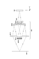
反射光学系の構成図。
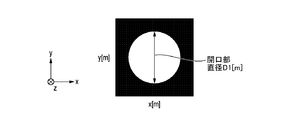
瞳関数を説明する図。
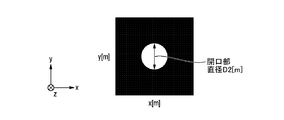
瞳関数を説明する図。
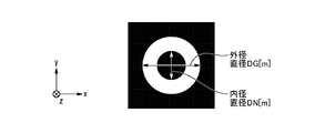
瞳関数を説明する図。
MTFを説明する図。
MTFを説明する図。
MTFを説明する図。
反射光学系の径とF値の対応を説明する図。
焦点検出動を説明するフローチャート。
焦点検出動を説明するフローチャート。
焦点検出領域を説明する図。
焦点検出評価値を説明する図。
焦点検出帯域による焦点検出評価値の変化を説明する図。
デジタルフィルタの周波数帯域を説明する図。
MTFとデジタルフィルタの対応を説明する図。
種々のMTFと焦点検出帯域での焦点検出評価値を説明する図。
焦点検出周波数の設定を説明する図。
MTFとデジタルフィルタの帯域の関係を説明する図。
焦点検出領域の画素信号を説明する図。
以下、添付図面を参照して実施形態を詳しく説明する。なお、以下の実施形態は特許請求の範囲に係る発明を限定するものではない。実施形態には複数の特徴が記載されているが、これらの複数の特徴の全てが発明に必須のものとは限らず、また、複数の特徴は任意に組み合わせられてもよい。さらに、添付図面においては、同一若しくは同様の構成に同一の参照番号を付し、重複した説明は省略する。
(撮像装置の構成)
図1A、1Bは、本発明の撮像装置の一実施形態であるレンズ交換式のデジタルカメラシステム200の構成を示す図である。デジタルカメラシステム200は、カメラ本体100と、カメラ本体100に交換可能に装着される、例えば撮影レンズ500、撮影レンズ600を有して構成される。図1Aは、カメラ本体100に反射光学系を有する撮影レンズ600が装着された状態を示し、図1Bは、カメラ本体100に通常の(反射光学系を有さない)撮影レンズ500が装着された状態を示している。
図1A、1Bは、本発明の撮像装置の一実施形態であるレンズ交換式のデジタルカメラシステム200の構成を示す図である。デジタルカメラシステム200は、カメラ本体100と、カメラ本体100に交換可能に装着される、例えば撮影レンズ500、撮影レンズ600を有して構成される。図1Aは、カメラ本体100に反射光学系を有する撮影レンズ600が装着された状態を示し、図1Bは、カメラ本体100に通常の(反射光学系を有さない)撮影レンズ500が装着された状態を示している。
撮影レンズ500、撮影レンズ600は、レンズの種別が異なり、カメラ本体100に対して交換可能に装着される。撮影レンズ500(または600)内の各レンズ群を透過した光束は、被写体像を受光して光電変換する撮像素子101へと導かれる。撮像素子101は、被写体像を電気信号に変換するマトリクス状に配置された画素部を備えて構成される。撮像素子101で被写体像を電気信号に変換して得られた画素信号には、カメラCPU104において、画像信号や焦点検出信号を得るための各種補正処理や、ライブビュー画像や記録画像やEVF画像へ変換するための処理等が施される。なお、本実施形態においては、これらの処理等をカメラCPU104で行っているが、これらの処理等は専用の回路を設けてその回路で行ってもよい。
操作部材105は、カメラの撮影モードや撮影条件(F値、ISO感度、露光時間など)を設定するための各種部材である。記憶媒体106は、フラッシュメモリであり、撮影した静止画や動画を記録するための媒体である。ファインダ内表示器107は、有機ELディスプレイや液晶ディスプレイ等の小型で高精細なディスプレイ109と、接眼レンズ108とを備えて構成される。外部表示器110は、裸眼視に適した画面サイズの有機ELディスプレイや液晶ディスプレイからなる。カメラ本体100の設定状態、ライブビュー画像、撮影済み画像等の各種情報は、ファインダ内表示器107や外部表示器110に表示される。
フォーカルプレンシャッタ111は撮像素子101の前面に配置されている。シャッタ駆動部112は例えばモーターであり、シャッタの羽根を駆動制御することにより、静止画を撮像する際の露光時間を制御する。カメラ側通信端子113は、撮影レンズ500(または600)を装着するためのカメラマウント部に設けられている。カメラ側通信端子113とレンズマウント部に設けられたレンズ側通信端子508とが接続されることにより、カメラCPU104と後述のレンズCPU507との間の通信が可能となる。
カメラCPU104には、ROMなどからなる不揮発性メモリ115と、RAMなどからなる揮発性メモリ116が接続されている。カメラCPU104は、不揮発性メモリ115に格納されたプログラムを揮発性メモリ116に展開して実行することにより、デジタルカメラシステム200全体を制御する。なお、不揮発性メモリ115には、プログラム以外の動作用の各種情報や、複数種類の撮影レンズの特性についての情報なども記憶されている。
撮影レンズ500(または600)は、カメラ本体100に対して着脱可能であり、図1Aでは反射光学系を有する撮影レンズ600が示され、図1Bでは焦点距離が可変なズームレンズである撮影レンズ500が示されている。カメラ本体100に装着されるレンズの種類は問わない。
被写体からの光束は、第1レンズ群501または601、第2レンズ群502(図1Bのみ)、第3レンズ群503を透過し、カメラ本体100内の撮像素子101の撮像面に被写体像として結像される。第1レンズ群601は、本実施形態の特徴である反射光学系を有するレンズ群である。詳細な構成については後述する。
第2レンズ群502は、光軸方向に進退して変倍を行なうバリエータ(変倍レンズ)として機能する。第3レンズ群503は光軸方向に進退して焦点調節を行なうフォーカスレンズとして機能する。第3レンズ群503は、ステッピングモーターなどを用いたフォーカス駆動部504によって駆動される。
図1Bのみに存在している絞り505は、撮影レンズに入射する光量を調節するための複数の絞り羽根で構成されている。絞り駆動部506は絞り羽根を所定の撮影F値になるまで絞り込み駆動する。図1Aの反射光学系においては、絞りと絞り駆動部とからなる絞り機構を設置することが困難であるため、存在しておらず、基本的には開放F値でのみ使用される。レンズCPU507は、レンズ側通信端子508及びカメラ側通信端子113を介してカメラCPU104と通信し、各種情報を送受信するとともに、カメラCPU104からの指令に基づいてフォーカス駆動部504や絞り駆動部506を駆動制御する。
レンズCPU507には、ROMなどからなる不揮発性メモリ510と、RAMなどからなる揮発性メモリ511が接続されている。レンズCPU507は、不揮発性メモリ510に格納されたプログラムを揮発性メモリ511に展開して実行することにより、撮影レンズ500(または600)全体を制御する。なお、不揮発性メモリ510には、プログラム以外の撮影レンズ固有の識別番号や光学情報なども記憶されている。
撮影レンズ500のズームレンジや開放F値は撮影意図に応じて設計されるが、反射光学系を有する撮影レンズ600は、基本的にはズームレンズや撮影絞りの制御機構は有さない。
次に、図2を用いて、図1Aで示した第1レンズ群601内の反射光学系について説明する。図2において、左の実線は被写体604を示しており、点線は被写体604の一点から出射された光線を示す。被写体604から出射された光はレンズ601Aを通って集光され、レンズ601Bで反射される。さらに、レンズ601Cで反射、屈折された光はレンズ601Bを通り、レンズ601Eを通過し、前述のフォーカスレンズ503を通過した後、撮像素子101の撮像面に結像される。レンズ601Bは、図2中の光路内で光を逆行させ反射させるような反射レンズである。また、レンズ601Cには、光路とは反対面(被写体側の面)に遮光部601Dが取り付けられる。このように、レンズ中で光路を折り返すことにより外形が小型でありながら、長焦点距離のレンズを実現することができる。
図3A~3Cは、本実施形態における撮影光学系のレンズ性能を示す瞳関数を説明する図である。瞳関数とは、レンズの射出瞳距離での開口面における光強度分布である。図の黒塗りの部分は開口率0%の遮光されている状態を示し、図の白色の部分は開口率100%の開口状態を示す。撮影レンズに収差が存在せず、絞り形状も理想的な円形である理想状態であったとすると、図3Aのように開口瞳形状(図3Aの白色の部分)は完全な円形となる。
撮影F値との対応を考えると、F値が小さい(開放F値に近い)状態では、図3Aのように瞳関数の開口部径D1が大きく、F値が大きい(絞り込み状態)では、図3Bのように瞳関数の開口部径D2が小さくなる。射出瞳距離zはレンズ固有の値であり、撮影F値が決まれば、射出瞳面上の開口部の直径Dの大きさは一意に決定される。本実施形態における撮影レンズ600の瞳関数の開口形状は、遮光部601Dで光線が遮断されることから、収差のない状態であっても図3Cのように、ドーナツ形状となる。図3Cの瞳関数のドーナツ形状の開口部における外側直径を外径DG、内側直径を内径DNと示す。外径DG、内径DNの大きさも、撮影レンズの射出瞳距離、撮影F値、遮光部601Dの径が決定されれば、一意に決まる値である。
また、この場合、撮影レンズの解像力を示すMTFは、瞳関数の自己相関であるOTFの絶対値で表される。図3A~図3Cの瞳関数のそれぞれに対応するMTF特性図を図4A~図4Cに示す。一般的な円形の瞳関数で示される図3A、図3Bのような開口形状では、開口部直径Dが大きいほど、図4A~4Cの縦軸であるMTFの値が高くなる。縦軸の値が大きいことは、レンズの解像力が高いことと同義である。横軸は周波数であるので、図4Aと図4Bでは、高周波数帯域の解像力でより顕著な差が生じる。また、MTFが0に落ちる周波数(レンズの解像力限界)をカットオフ周波数と呼び、図4A、図4BではCOfq1、COfq2で示されている。カットオフ周波数も開口部の大きさDによって異なり、COfq=D/2λf(λ:光の波長、f:撮影光学系の焦点距離)で求められる。
瞳関数が理想の円形形状である場合は、カットオフ周波数は、上記式で求められるが、実際の撮影光学系では、撮影絞りは円形形状とは異なる場合も多く、撮影条件(収差、撮像面上の座標x,y等)によっても異なり、MTFは複雑に変化する。また、図3Cのような本実施形態における反射光学系を有するレンズのドーナツ型の瞳関数では、図4CのようなMTF特性図MTF3を示す。図4Cにおけるカットオフ周波数COfq3は、外径DG=D1である場合には、COfq1と等しい。言い換えると、カットオフ周波数は、外径DGの大きさによって決まる値である。低周波領域では、瞳関数とMTFの自己相関の関係からもわかるように、外径と内径の差分の開口部(以下、内外径差)のMTFと近くなる。つまり、図3Cにおいて、DG-DN=D2である場合には、低周波領域(<COfq2)では、図4Cで示したMTF3は、図4Bで示したMTF2に近い値を示す。このように、本実施形態の光学系では、瞳関数が特殊な形状となるが、射出瞳面上での外径、内径の大きさDG、DNは、図2で示した遮光部601Dの直径や開放F値から設計的に決まる値であるので、レンズ性能であるMTFも図4Cのように予測可能である。
撮影レンズ600、カメラ本体100が一体型のカメラであれば、予め計算したMTFを保持しておけばよい。一方、交換レンズ系においては、撮影レンズ600は、内径の大きさDN、外径の大きさDG、瞳関数P、レンズ射出瞳距離LPO、レンズMTF等から適宜選択されたパラメータの値を不揮発性メモリ510内に保有する。そして、レンズ側通信端子508及びカメラ側通信端子113を介してカメラ本体100にレンズの反射光学系の形状に関する情報を通信する。また、内径の大きさDN、外径の大きさDGに代わる値として、図5に示すように、径に対応するF値の情報を通信してもよい。たとえば、外径の大きさDG=F2、内外径差=F4として情報を通信してもよい。また、交換レンズ系における一部の情報をカメラ側の不揮発性メモリ115に保有し、レンズからは一部の情報のみ通信するようにしてもよい。
次に、本実施形態における焦点検出動作について図6A、6Bを用いて説明する。本実施形態では、一般的にコントラストAF(オートフォーカス)と呼ばれる手法で焦点検出動作を行う。
まず、図6AのステップS1では、焦点検出領域の設定を行う。例として、カメラCPU104で図7のような撮影画像が得られている場合には、主被写体として画面中央部付近にある顔が検出され、焦点検出領域10が設定される。焦点検出領域10の大きさ、位置座標(x,y)については、撮影者が任意に設定してもよいし、図7のように撮影画像に顔が含まれている場合には、顔検出機能等により自動設定されてもよい。
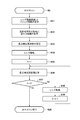
次に、ステップS2ではAFスキャン動作を行う。AFスキャン動作では、フォーカスレンズ503を光軸に沿って移動させながら、ステップS11で設定されるレンズ駆動回数n、ステップ間隔iで、合焦度を示す焦点検出評価値を計算する。ここで、ステップS2で行われるAFスキャン動作について、図6Bのフローチャートを用いて詳細に説明する。
まず、AFスキャン動作が開始されると、ステップS11においてレンズ駆動回数n、ステップ間隔iを設定する。コントラストAFでは、フォーカスレンズを光軸方向に移動させながら焦点評価値を取得し、焦点評価値が極大(被写体のコントラストが最大)になったところでフォーカスレンズ503を停止させることにより、ピントの合った画像を取得する。よって、フォーカスレンズの駆動回数n、ステップ間隔iはコントラストの極大値が取得できる範囲で設定されるべきである。
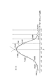
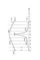
たとえば、今、図8の横軸のようにフォーカスレンズ位置zを変化させた時、コントラストカーブCcurvが図8上のCcurvのように取得され、各フォーカスレンズ位置での焦点評価値Eval(n)が得られるとする。この場合、ステップS11で設定されるレンズ駆動回数、ステップ間隔は、レンズ駆動回数n=10、ステップ間隔=iで設定されてもよいし、レンズ駆動回数n=7では極大値は検出できているので、n=7で検出を停止してもよい。また、次のような方法もよく知られた手法である。まず、図9のように、最初にレンズ駆動回数n=4、ステップ間隔3iで粗くキャンをすることによりだいたいの焦点評価値の極大位置を見つける(図9中Ccurv1上のEval1(4)とEval1(7)の間)。そして、より高精度に焦点位置を検出するために、極大値付近をステップ間隔iで細かくスキャン(図9中Ccurv3上のEval3(4)からEval3(7))することにより図8と同等の焦点位置を得る。この動作を以下、粗スキャン(粗スキャン動作)、密スキャン(密スキャン動作)と呼ぶ。この場合は、図9では粗スキャンのレンズ駆動回数=4、ステップ間隔=3iとなり、密スキャンのレンズ駆動回数=4、ステップ間隔=iとなる。それぞれの焦点評価値の計算方法、適切なコントラストカーブの設定方法は後述する。
次に、ステップS12では、撮影条件(ズーム、フォーカス、F値、像高)に応じた反射光学系の形状に関する情報を、カメラCPU104が、撮影レンズ600の不揮発性メモリ510またはカメラ本体100の不揮発性メモリ115から取得する。情報の内容は、前述したように、内径の大きさDN、外径の大きさDG、瞳関数P、レンズ射出瞳距離LPO、レンズMTF、径に対応するF値の情報などから適宜選択される。カメラCPU104は、これらの情報を、前述の不揮発性メモリ510または115から、撮影レンズ600との通信により、またはカメラ本体100内との通信により取得する。
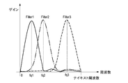
次に、ステップS13では、焦点検出周波数を設定する。ここでは、デジタルフィルタの焦点検出周波数帯域の設定を行う。図10は、デジタルフィルタの周波数帯域の例を示す図である。ここで示すナイキスト周波数は、撮像素子101の画素ピッチから決まる値であり、例えば、撮像素子101の画素ピッチが4ミクロンであったとすると、ナイキスト周波数=1/(0.004×2)=125(lp/mm:ラインペア/ミリメートル)と求めることができる。これは、撮像素子101上で125(lp/mm)より細かい被写体像は解像できないことを示す。
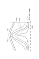
図10の横軸は周波数、縦軸はゲインを示しており、実線で示したFilter1は中心周波数fq1を持つ。Filter2、Filter3はFilter1よりも高域の周波数帯域を持ち、中心周波数はそれぞれ、fq2、fq3である。一般的に、周波数帯域が高いほど、コントラスト評価値は急峻な変化を示す。よって、Filter1のような周波数特性を持つフィルタ処理を施した際に得られる焦点評価値が図9のコントラストカーブCcurv1だったとすると、Filter3のような周波数特性を持つフィルタ処理を施した際に得られる焦点評価値は、コントラストカーブCcurv1よりも急峻なコントラストカーブCcurv3のようになる。これは、同じボケ量(フォーカスレンズ駆動量)でも、低周波成分よりも高周波成分のレンズMTFの方が相対的に失われる量が多いことによる。
コントラストAFによる焦点検出では、一般的に焦点評価値Evalが極大となったところにフォーカスレンズを駆動させるため、コントラストカーブCcurvの形状も焦点検出精度に大きく影響を与える。たとえば、図9では、粗スキャン中の焦点評価値が極大のフォーカスレンズ位置はz=7であるが、密スキャン中の焦点評価値が極大のフォーカスレンズ位置はz=6である。粗スキャン中は、ステップ間隔が広いため、コントラストカーブCcurv1はなだらかな変化を示すことが望ましい。これは、粗スキャン時に、急峻なコントラストカーブCurv3で焦点検出を行うとステップ間隔が広いことにより極大値を逃す恐れがあるからである。そのため、粗スキャンの場合は、ステップS13で設定される焦点検出周波数は低域であることが望ましい。逆に、密スキャンの時は、ステップ間隔が狭いため、コントラストカーブCcurv3のように急峻なカーブを用いた方が、焦点検出評価値Evalの高精度な極大値検出が可能となる。そのため、ステップS13で設定される焦点検出周波数は高域であることが望ましい。
さらに、コントラストカーブCcurvは、焦点検出周波数とレンズのMTFの掛け合わせで決まる値である。図4で示したレンズのMTFと図10で示した焦点検出周波数を重ねて考える。今、ナイキスト周波数とレンズのカットオフ周波数が同じであったとすると、図11のように横軸周波数/縦軸ゲインのグラフに重ねて考えることができる。図11では、Filter1、Fileter2、Filter3の周波数を一点鎖線、MTF1、MTF2を点線、MTF3を実線で示している。ここで示しているMTFは焦点評価値が極大(合焦状態)のフォーカスレンズ位置(たとえばフォーカスレンズ位置z=6)のMTFであり、デフォーカス(合焦していない)状態では、それぞれのMTF特性は異なる。しかし、合焦時のMTFよりもデフォーカス状態でのMTFゲインは低く、デフォーカスが大きくなるごとに一般的には相対的にMTFの値は低くなる。この時、コントラスト評価値Eval(z=6)は、MTFのゲインとFilterのゲインの乗算値に比例した値に近い。
つまり、図12に示すように、デジタルフィルタFilter1をかけて得られる焦点評価値Evalは、MTF2、MTF3ではほとんど変わらず、Ccurv1である。そして、MTF1では、MTF2、MTF3よりも出力が高いため、Ccurv1-1のように焦点評価値も大きな出力になる。同様に、デジタルフィルタFilter2をかけて得られる焦点評価値Evalは、MTF1では、Ccurv2-1、MTF2ではCcurv2、MTF3ではCcurv2-2となり、それぞれ異なる。デジタルフィルタFilter3をかけて得られる焦点評価値Evalは、MTF1、MTF3ではほとんど変わらず、Ccurv3であり、MTF2では、MTFのゲインが0のため、焦点評価値が得られない(不図示)。
MTFは撮影光学系の構成によって既知の値であるので、コントラストAFを行う際には、予めデジタルフィルタの焦点評価帯域を適切に設定することにより所望のコントラストカーブCcurvを得ることができる。その際に、本実施形態に示した反射光学系を有するレンズのような特殊な撮影光学系の場合には、MTFがMTF3の形状のような変化を示すことを加味して焦点検出周波数を設定する必要がある。
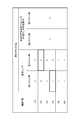
交換レンズ系において、一般的な撮影レンズ500で粗スキャン、密スキャン時に選択されるデジタルフィルタが図13の左欄のように設定されている場合、本実施形態の反射光学系を有する撮影レンズ600の内径、内外径差に相当する撮影F値等が通信された場合には、図13の太枠で示されたテーブルを参照する。つまり、粗スキャン時は内外径差F4に対応するF4.0と同様のFilter1を選択し、密スキャン時は外径F2に対応するF2.0と同様のFilter3を選択すればよい。このように、ステップS13では、撮影レンズ600の反射光学系の形状に関する情報に合わせて焦点評価値を得る際の信号処理方法の切り替えを行う。ここでは、デジタルフィルタの切り替え方法について説明したが、撮影レンズ600の反射光学系の形状に関する情報に合わせてステップ間隔iを設定してもよい。また、撮影レンズ600のMTF3に対し、図14に示したようなローパスFilter4を施すと、MTF2の特性と同じとなるため、通常レンズのF4.0と同じ特性として扱うこともできる。
次に、ステップS14では、フォーカスレンズ503を、光軸に沿ってAFスキャンの1ステップの移動間隔分駆動する。そして、ステップS15では、フォーカスレンズ503を駆動した回数を示す変数kを1に設定する。
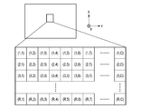
次に、ステップS16では、焦点評価値Evalを計算する。ここでは、ステップS1で設定された焦点検出領域に対して、ステップS13で示されたデジタルフィルタを畳み込み演算等することにより、各フォーカスレンズ位置zでの焦点評価値Evalを得る。たとえば、ステップS13で設定されたFilter1が(TAP1,TAP2,TAP3)というフィルタタップを有し、焦点検出領域での画素値gaso(x,y)が図15に示す配列であったとすると、デジタルフィルタ演算後の画素配列値f(x,y)は、
f(x,y)=TAP1×gaso(x,y)+TAP2×gaso(x+1,y+1)+TAP3×gaso(x+2,y+2)
で求めることができる。(TAP1,TAP2,TAP3)のタップ数(ここでは3)は、ステップS13で前述した焦点検出周波数に応じて設定されればよい。フィルタ演算後のf(x,y)の画素値の中で、絶対値として最も大きい値を算出すれば、例えば、焦点検出評価値Evalが求められる。
f(x,y)=TAP1×gaso(x,y)+TAP2×gaso(x+1,y+1)+TAP3×gaso(x+2,y+2)
で求めることができる。(TAP1,TAP2,TAP3)のタップ数(ここでは3)は、ステップS13で前述した焦点検出周波数に応じて設定されればよい。フィルタ演算後のf(x,y)の画素値の中で、絶対値として最も大きい値を算出すれば、例えば、焦点検出評価値Evalが求められる。
ここで説明した焦点評価値の算出方法は一例であり、デジタルフィルタは二次元であってもよいし、1ライン毎の焦点評価値を求めてもよい。また、画像信号のフーリエ変換等を行ってから図10のデジタルフィルタゲインをかけて焦点評価値Evalを求めてもよく、画像中のコントラストを示す焦点評価値Evalを示すことができれば方法は問わない。また、画像信号の加算状態(静止画用、ライブビュー表示用、動画用等)によって、記録周波数が変化するのに伴い、デジタルフィルタの帯域設定を行ってもよい。
次に、ステップS17では、変数kがステップS11で設定されたレンズ駆動回数nに達しているか否かを判定する。変数kがレンズ駆動回数nに達していれば、ステップS20に進んで、AFスキャン動作を終了し、達していなければ、ステップS18に進み、フォーカスレンズ503をAFスキャンの1ステップ分駆動する。
ステップS19では、変数kをインクリメントし、ステップS15に戻る。そして、ステップS15~S18の動作を、ステップS11で設定されたレンズ駆動回数nだけ繰り返す。
なお、前述したように、AFスキャンを粗スキャン、密スキャンに分けて行う場合には、粗スキャン用と、密スキャン用に、ステップS13~S19の動作を2回繰り返して行う。
図6Aの説明に戻り、ステップS3では、ステップS16で得られた焦点評価値Evalからピーク位置演算を行う。図8のような焦点評価値Evalが得られていた場合、極大値であるEval(6)を焦点評価値ピークとして、フォーカスレンズ位置z=6を焦点評価値ピーク位置(合焦位置)としてもよい。しかし、より高精度には、焦点評価値の極大値付近の焦点評価値Evalと、ステップ間隔、フォーカスレンズ位置zを使って内挿計算する等して焦点評価値ピーク位置であるフォーカスレンズ位置Pを求める。内挿計算の方法は線形補間でも構わないし、得られた離散的な焦点評価値Evalから高次近似で極大値を求めても構わない。
図8の例では、極大値付近の3点を使って線形補間で補間演算を行い、フォーカスレンズ位置z=5とz=6の間に極大値があると算出され、フォーカスレンズ位置Pはz=5.7付近となる。
次に、ステップS4では、各焦点検出領域のピーク位置の合焦判定(合焦状態判定)を行い、ステップS5へ進む。ここでは、フォーカスレンズ位置に対するAF評価値の極大値の有無を判定し、極大値が存在する場合のフォーカスレンズ位置を算出する。更に、極大値近傍のAF評価値の変化曲線の信頼性を評価する。この信頼性評価では、求められたAF評価値が、被写体の光学像が撮像素子101上に結像したために極大値をとったのか、その他の外乱により極大値をとったのかを判定する。
合焦判定の詳細な方法としては、例えば、特開2010-078810号公報の図10から図13で説明されているような方法を用いればよい。つまり、合焦状態を示すAF評価値が山状になっているか否かを、焦点評価値の最大値と最小値の差、一定値(SlopeThr)以上の傾きで傾斜している部分の長さ、および傾斜している部分の勾配から判断する。これにより、合焦判定を行うことができる。合焦判定でNGとなった場合には、ステップS6の合焦表示で非合焦の表示を行うか、ステップS2のAFスキャン動作をやり直す。
次に、ステップS5では、ステップS3で求めたフォーカスレンズ位置Pまで、フォーカスレンズ503を光軸方向に駆動させる。
最後に、ステップS6では、合焦表示を行う。ステップS4で合焦判定OKとなった場合には、図7の焦点検出領域に合焦表示(たとえば、枠を緑色に表示)を行うことによりユーザーに焦点検出動作の終了を知らせる。ステップS4で合焦判定がNGとなった場合には、図7の焦点検出領域に非合焦表示(たとえば、枠を赤色に表示)を行うことによりユーザーに焦点検出動作の終了を知らせる。以上の動作を行い、焦点調節動作を完了する。
以上説明したように、本実施形態によれば、反射光学系を含むレンズを有する撮像装置においても、高精度に焦点検出を行うことが可能となる。
(他の実施形態)
また本発明は、上述の実施形態の1以上の機能を実現するプログラムを、ネットワーク又は記憶媒体を介してシステム又は装置に供給し、そのシステム又は装置のコンピュータにおける1つ以上のプロセッサーがプログラムを読み出し実行する処理でも実現できる。また、1以上の機能を実現する回路(例えば、ASIC)によっても実現できる。
また本発明は、上述の実施形態の1以上の機能を実現するプログラムを、ネットワーク又は記憶媒体を介してシステム又は装置に供給し、そのシステム又は装置のコンピュータにおける1つ以上のプロセッサーがプログラムを読み出し実行する処理でも実現できる。また、1以上の機能を実現する回路(例えば、ASIC)によっても実現できる。
本発明は上記実施の形態に制限されるものではなく、本発明の精神及び範囲から離脱することなく、様々な変更及び変形が可能である。従って、本発明の範囲を公にするために請求項を添付する。
本願は、2019年6月5日提出の日本国特許出願特願2019-105607を基礎として優先権を主張するものであり、その記載内容の全てを、ここに援用する。
Claims (14)
- 被写体像を撮像する撮像素子と、
撮影光学系に含まれるフォーカスレンズを前記撮影光学系の光軸に沿って移動させるスキャン動作を行いながら、前記被写体像を前記撮像素子により光電変換して得られた画像信号に基づいて、被写体の合焦度を示す焦点評価値を算出し、該焦点評価値が最大になるフォーカスレンズの位置を検出する焦点検出手段と、を備え、
前記焦点検出手段は、前記撮影光学系が、光束の一部が遮光される反射光学系を含む場合に、前記反射光学系の形状に関する情報に基づいて、前記焦点評価値の算出方法、または、前記スキャン動作における前記フォーカスレンズの制御方法を設定することを特徴とする撮像装置。 - 前記反射光学系の形状に関する情報は、前記反射光学系の瞳関数に関する情報を含むことを特徴とする請求項1に記載の撮像装置。
- 前記反射光学系の形状に関する情報は、前記反射光学系の射出瞳面上において前記瞳関数に対応するドーナツ形状の開口の内径と外径に関する情報を含むことを特徴とする請求項2に記載の撮像装置。
- 前記反射光学系の形状に関する情報は、前記ドーナツ形状の開口の内径と外径に対応するF値の情報を含むことを特徴とする請求項3に記載の撮像装置。
- 前記反射光学系の形状に関する情報は、前記反射光学系のMTFに関する情報を含むことを特徴とする請求項1に記載の撮像装置。
- 前記焦点検出手段は、前記反射光学系の形状に関する情報に基づいて、前記焦点評価値を算出する際の焦点検出周波数を設定することを特徴とする請求項1乃至5のいずれか1項に記載の撮像装置。
- 前記焦点検出手段は、前記フォーカスレンズのスキャン動作として、前記フォーカスレンズの1ステップの移動間隔が第1の間隔である粗スキャン動作と、前記フォーカスレンズの1ステップの移動間隔が前記第1の間隔よりも狭い密スキャン動作とを行って、前記焦点評価値を算出することを特徴とする請求項1に記載の撮像装置。
- 前記焦点検出手段は、前記粗スキャン動作で得られた前記焦点評価値の最大値に基づいて、前記密スキャン動作により、前記焦点評価値が最大になる前記フォーカスレンズの位置をさらに細かく算出することを特徴とする請求項7に記載の撮像装置。
- 前記焦点検出手段は、前記反射光学系の射出瞳面上において瞳関数に対応するドーナツ形状の開口の内径に相当する開口を有するレンズに対する粗スキャンで用いる焦点検出周波数を、前記撮影光学系の粗スキャンにおける焦点検出周波数として設定し、前記ドーナツ形状の開口部の外径に相当する開口を有するレンズの密スキャンで用いる焦点検出周波数を、前記撮影光学系の密スキャンにおける焦点検出周波数として設定することを特徴とする請求項7または8に記載の撮像装置。
- 前記焦点検出手段は、前記反射光学系の形状に関する情報に基づいて、前記スキャン動作における前記フォーカスレンズの1ステップの移動間隔を設定することを特徴とする請求項1乃至5のいずれか1項に記載の撮像装置。
- 前記焦点検出手段は、前記反射光学系の射出瞳面上において瞳関数に対応するドーナツ形状の開口の内径に相当する開口を有するレンズのMTF特性に相当するフィルタを前記画像信号にかけて、前記焦点評価値を算出することを特徴とする請求項1乃至3のいずれか1項に記載の撮像装置。
- 被写体像を撮像する撮像素子を備える撮像装置を制御する方法であって、
撮影光学系に含まれるフォーカスレンズを前記撮影光学系の光軸に沿って移動させるスキャン動作を行いながら、前記被写体像を前記撮像素子により光電変換して得られた画像信号に基づいて、被写体の合焦度を示す焦点評価値を算出し、該焦点評価値が最大になるフォーカスレンズの位置を検出する焦点検出工程を有し、
前記焦点検出工程では、前記撮影光学系が、光束の一部が遮光される反射光学系を含む場合に、前記反射光学系の形状に関する情報に基づいて、前記焦点評価値の算出方法、または、前記スキャン動作における前記フォーカスレンズの制御方法を設定することを特徴とする撮像装置の制御方法。 - 請求項12に記載の制御方法を、コンピュータに実行させるためのプログラム。
- 請求項12に記載の制御方法を、コンピュータに実行させるためのプログラムを記憶したコンピュータが読み取り可能な記憶媒体。
Priority Applications (1)
| Application Number | Priority Date | Filing Date | Title |
|---|---|---|---|
| US17/540,481 US11825195B2 (en) | 2019-06-05 | 2021-12-02 | Image capturing apparatus using information relating to a shape of the reflective optical system, method of controlling the same, and storage medium |
Applications Claiming Priority (2)
| Application Number | Priority Date | Filing Date | Title |
|---|---|---|---|
| JP2019105607A JP7240261B2 (ja) | 2019-06-05 | 2019-06-05 | 撮像装置及びその制御方法、プログラム、記憶媒体 |
| JP2019-105607 | 2019-06-05 |
Related Child Applications (1)
| Application Number | Title | Priority Date | Filing Date |
|---|---|---|---|
| US17/540,481 Continuation US11825195B2 (en) | 2019-06-05 | 2021-12-02 | Image capturing apparatus using information relating to a shape of the reflective optical system, method of controlling the same, and storage medium |
Publications (1)
| Publication Number | Publication Date |
|---|---|
| WO2020246346A1 true WO2020246346A1 (ja) | 2020-12-10 |
Family
ID=73649195
Family Applications (1)
| Application Number | Title | Priority Date | Filing Date |
|---|---|---|---|
| PCT/JP2020/020992 Ceased WO2020246346A1 (ja) | 2019-06-05 | 2020-05-27 | 撮像装置及びその制御方法、プログラム、記憶媒体 |
Country Status (3)
| Country | Link |
|---|---|
| US (1) | US11825195B2 (ja) |
| JP (1) | JP7240261B2 (ja) |
| WO (1) | WO2020246346A1 (ja) |
Cited By (1)
| Publication number | Priority date | Publication date | Assignee | Title |
|---|---|---|---|---|
| CN113556470A (zh) * | 2021-09-18 | 2021-10-26 | 浙江宇视科技有限公司 | 一种镜头的调焦方法、装置、计算机设备和存储介质 |
Families Citing this family (1)
| Publication number | Priority date | Publication date | Assignee | Title |
|---|---|---|---|---|
| JP7676211B2 (ja) * | 2021-04-28 | 2025-05-14 | キヤノン株式会社 | 光学系および撮像装置 |
Citations (4)
| Publication number | Priority date | Publication date | Assignee | Title |
|---|---|---|---|---|
| JPS51124560A (en) * | 1975-04-18 | 1976-10-30 | Matsushita Electric Works Ltd | Lawn mower |
| JPH07222059A (ja) * | 1993-10-04 | 1995-08-18 | Raytheon Co | 合焦平面アレー補償技術を含む光学システム |
| US5841574A (en) * | 1996-06-28 | 1998-11-24 | Recon/Optical, Inc. | Multi-special decentered catadioptric optical system |
| CN104062746A (zh) * | 2014-06-23 | 2014-09-24 | 中国科学院光电技术研究所 | 一种大数值孔径的折反射浸没投影光学系统 |
Family Cites Families (11)
| Publication number | Priority date | Publication date | Assignee | Title |
|---|---|---|---|---|
| JPS5342638U (ja) * | 1976-09-16 | 1978-04-12 | ||
| JP2004085725A (ja) | 2002-08-23 | 2004-03-18 | Sony Corp | 撮像レンズ、集光光学素子及び撮像装置 |
| JP5153542B2 (ja) | 2008-09-25 | 2013-02-27 | キヤノン株式会社 | 自動焦点調節装置および焦点調節方法 |
| JP5441521B2 (ja) * | 2009-06-30 | 2014-03-12 | キヤノン株式会社 | ズームレンズ及びそれを有する撮像装置 |
| US8964102B2 (en) * | 2011-06-29 | 2015-02-24 | Maxim Integrated Products, Inc. | Self-calibrated ringing compensation for an autofocus actuator in a camera module |
| TWI440951B (zh) * | 2011-11-09 | 2014-06-11 | Altek Corp | 鏡頭致動裝置及其鏡頭致動方法 |
| JP2014029353A (ja) * | 2012-07-31 | 2014-02-13 | Sony Corp | 焦点調整装置および焦点調整方法 |
| US9386222B2 (en) * | 2014-06-20 | 2016-07-05 | Qualcomm Incorporated | Multi-camera system using folded optics free from parallax artifacts |
| JP6381434B2 (ja) * | 2014-12-16 | 2018-08-29 | キヤノン株式会社 | フォーカス制御装置、光学機器およびフォーカス制御方法 |
| US9933604B1 (en) * | 2016-09-05 | 2018-04-03 | Weimin Lu | Compact catadioptric lenses and lens systems with improved image quality and methods of using same |
| JP7303668B2 (ja) * | 2019-06-05 | 2023-07-05 | キヤノン株式会社 | 撮像装置及びその制御方法、カメラシステム、プログラム、記憶媒体 |
-
2019
- 2019-06-05 JP JP2019105607A patent/JP7240261B2/ja active Active
-
2020
- 2020-05-27 WO PCT/JP2020/020992 patent/WO2020246346A1/ja not_active Ceased
-
2021
- 2021-12-02 US US17/540,481 patent/US11825195B2/en active Active
Patent Citations (4)
| Publication number | Priority date | Publication date | Assignee | Title |
|---|---|---|---|---|
| JPS51124560A (en) * | 1975-04-18 | 1976-10-30 | Matsushita Electric Works Ltd | Lawn mower |
| JPH07222059A (ja) * | 1993-10-04 | 1995-08-18 | Raytheon Co | 合焦平面アレー補償技術を含む光学システム |
| US5841574A (en) * | 1996-06-28 | 1998-11-24 | Recon/Optical, Inc. | Multi-special decentered catadioptric optical system |
| CN104062746A (zh) * | 2014-06-23 | 2014-09-24 | 中国科学院光电技术研究所 | 一种大数值孔径的折反射浸没投影光学系统 |
Cited By (2)
| Publication number | Priority date | Publication date | Assignee | Title |
|---|---|---|---|---|
| CN113556470A (zh) * | 2021-09-18 | 2021-10-26 | 浙江宇视科技有限公司 | 一种镜头的调焦方法、装置、计算机设备和存储介质 |
| US12445723B2 (en) | 2021-09-18 | 2025-10-14 | Zhejiang Uniview Technologies Co., Ltd. | Method and apparatus for lens focusing, computer device and storage medium |
Also Published As
| Publication number | Publication date |
|---|---|
| US11825195B2 (en) | 2023-11-21 |
| US20220094841A1 (en) | 2022-03-24 |
| JP7240261B2 (ja) | 2023-03-15 |
| JP2020197685A (ja) | 2020-12-10 |
Similar Documents
| Publication | Publication Date | Title |
|---|---|---|
| US10212334B2 (en) | Focusing adjustment apparatus and focusing adjustment method | |
| JP3992992B2 (ja) | 被写体像取得装置 | |
| US10313578B2 (en) | Image capturing apparatus and method for controlling image capturing apparatus | |
| JP7303668B2 (ja) | 撮像装置及びその制御方法、カメラシステム、プログラム、記憶媒体 | |
| KR100755288B1 (ko) | 카메라, 그 제어방법 및 기억 매체 | |
| CN109981945B (zh) | 摄像光学系统 | |
| JP5653035B2 (ja) | 撮像装置、焦点検出方法、および制御方法 | |
| US8634711B2 (en) | Image capture apparatus and method | |
| JP4794963B2 (ja) | 撮像装置および撮像プログラム | |
| JP6298362B2 (ja) | 撮像装置及びその制御方法、及び撮像システム | |
| US11825195B2 (en) | Image capturing apparatus using information relating to a shape of the reflective optical system, method of controlling the same, and storage medium | |
| JP6890937B2 (ja) | 焦点検出装置、撮像装置、および焦点検出方法 | |
| US12105404B2 (en) | Lens apparatus, image pickup apparatus, control method of lens apparatus, and storage medium | |
| JP5409588B2 (ja) | 焦点調節方法、焦点調節プログラムおよび撮像装置 | |
| JP4125176B2 (ja) | デジタルカメラ付地上望遠鏡 | |
| JP2003322791A (ja) | 焦点調節装置、撮像装置および光学機器 | |
| JP7676211B2 (ja) | 光学系および撮像装置 | |
| JP2009031562A (ja) | 受光素子、受光装置、焦点検出装置、カメラ | |
| JP2017191212A (ja) | 焦点検出装置 | |
| WO2025074900A1 (ja) | 撮像装置 | |
| JP2013054288A (ja) | 焦点検出装置、撮像装置 | |
| JP2013083768A (ja) | 焦点検出装置および撮像装置 | |
| JP2001124981A (ja) | 撮影装置 | |
| JP2019053315A (ja) | 焦点調節装置および撮像装置 | |
| JP2018205762A (ja) | 焦点調節装置 |
Legal Events
| Date | Code | Title | Description |
|---|---|---|---|
| 121 | Ep: the epo has been informed by wipo that ep was designated in this application |
Ref document number: 20818841 Country of ref document: EP Kind code of ref document: A1 |
|
| NENP | Non-entry into the national phase |
Ref country code: DE |
|
| 122 | Ep: pct application non-entry in european phase |
Ref document number: 20818841 Country of ref document: EP Kind code of ref document: A1 |