WO2020246337A1 - 熱交換器、冷凍サイクル装置 - Google Patents
熱交換器、冷凍サイクル装置 Download PDFInfo
- Publication number
- WO2020246337A1 WO2020246337A1 PCT/JP2020/020920 JP2020020920W WO2020246337A1 WO 2020246337 A1 WO2020246337 A1 WO 2020246337A1 JP 2020020920 W JP2020020920 W JP 2020020920W WO 2020246337 A1 WO2020246337 A1 WO 2020246337A1
- Authority
- WO
- WIPO (PCT)
- Prior art keywords
- refrigerant
- flow path
- heat medium
- cooler
- radiator
- Prior art date
- Legal status (The legal status is an assumption and is not a legal conclusion. Google has not performed a legal analysis and makes no representation as to the accuracy of the status listed.)
- Ceased
Links
Images


Classifications
-
- B—PERFORMING OPERATIONS; TRANSPORTING
- B60—VEHICLES IN GENERAL
- B60H—ARRANGEMENTS OF HEATING, COOLING, VENTILATING OR OTHER AIR-TREATING DEVICES SPECIALLY ADAPTED FOR PASSENGER OR GOODS SPACES OF VEHICLES
- B60H1/00—Heating, cooling or ventilating devices
- B60H1/32—Cooling devices
-
- F—MECHANICAL ENGINEERING; LIGHTING; HEATING; WEAPONS; BLASTING
- F25—REFRIGERATION OR COOLING; COMBINED HEATING AND REFRIGERATION SYSTEMS; HEAT PUMP SYSTEMS; MANUFACTURE OR STORAGE OF ICE; LIQUEFACTION SOLIDIFICATION OF GASES
- F25B—REFRIGERATION MACHINES, PLANTS OR SYSTEMS; COMBINED HEATING AND REFRIGERATION SYSTEMS; HEAT PUMP SYSTEMS
- F25B1/00—Compression machines, plants or systems with non-reversible cycle
-
- F—MECHANICAL ENGINEERING; LIGHTING; HEATING; WEAPONS; BLASTING
- F25—REFRIGERATION OR COOLING; COMBINED HEATING AND REFRIGERATION SYSTEMS; HEAT PUMP SYSTEMS; MANUFACTURE OR STORAGE OF ICE; LIQUEFACTION SOLIDIFICATION OF GASES
- F25B—REFRIGERATION MACHINES, PLANTS OR SYSTEMS; COMBINED HEATING AND REFRIGERATION SYSTEMS; HEAT PUMP SYSTEMS
- F25B39/00—Evaporators; Condensers
- F25B39/02—Evaporators
-
- F—MECHANICAL ENGINEERING; LIGHTING; HEATING; WEAPONS; BLASTING
- F25—REFRIGERATION OR COOLING; COMBINED HEATING AND REFRIGERATION SYSTEMS; HEAT PUMP SYSTEMS; MANUFACTURE OR STORAGE OF ICE; LIQUEFACTION SOLIDIFICATION OF GASES
- F25B—REFRIGERATION MACHINES, PLANTS OR SYSTEMS; COMBINED HEATING AND REFRIGERATION SYSTEMS; HEAT PUMP SYSTEMS
- F25B39/00—Evaporators; Condensers
- F25B39/04—Condensers
-
- F—MECHANICAL ENGINEERING; LIGHTING; HEATING; WEAPONS; BLASTING
- F25—REFRIGERATION OR COOLING; COMBINED HEATING AND REFRIGERATION SYSTEMS; HEAT PUMP SYSTEMS; MANUFACTURE OR STORAGE OF ICE; LIQUEFACTION SOLIDIFICATION OF GASES
- F25B—REFRIGERATION MACHINES, PLANTS OR SYSTEMS; COMBINED HEATING AND REFRIGERATION SYSTEMS; HEAT PUMP SYSTEMS
- F25B5/00—Compression machines, plants or systems, with several evaporator circuits, e.g. for varying refrigerating capacity
- F25B5/02—Compression machines, plants or systems, with several evaporator circuits, e.g. for varying refrigerating capacity arranged in parallel
-
- F—MECHANICAL ENGINEERING; LIGHTING; HEATING; WEAPONS; BLASTING
- F28—HEAT EXCHANGE IN GENERAL
- F28D—HEAT-EXCHANGE APPARATUS, NOT PROVIDED FOR IN ANOTHER SUBCLASS, IN WHICH THE HEAT-EXCHANGE MEDIA DO NOT COME INTO DIRECT CONTACT
- F28D9/00—Heat-exchange apparatus having stationary plate-like or laminated conduit assemblies for both heat-exchange media, the media being in contact with different sides of a conduit wall
- F28D9/02—Heat-exchange apparatus having stationary plate-like or laminated conduit assemblies for both heat-exchange media, the media being in contact with different sides of a conduit wall the heat-exchange media travelling at an angle to one another
-
- F—MECHANICAL ENGINEERING; LIGHTING; HEATING; WEAPONS; BLASTING
- F28—HEAT EXCHANGE IN GENERAL
- F28F—DETAILS OF HEAT-EXCHANGE AND HEAT-TRANSFER APPARATUS, OF GENERAL APPLICATION
- F28F3/00—Plate-like or laminated elements; Assemblies of plate-like or laminated elements
- F28F3/08—Elements constructed for building-up into stacks, e.g. capable of being taken apart for cleaning
-
- F—MECHANICAL ENGINEERING; LIGHTING; HEATING; WEAPONS; BLASTING
- F28—HEAT EXCHANGE IN GENERAL
- F28F—DETAILS OF HEAT-EXCHANGE AND HEAT-TRANSFER APPARATUS, OF GENERAL APPLICATION
- F28F9/00—Casings; Header boxes; Auxiliary supports for elements; Auxiliary members within casings
Definitions
- the present disclosure relates to a heat exchanger that exchanges heat between a refrigerant containing oil and a heat medium, and a refrigeration cycle device.
- the temperature of the refrigerant becomes very low on the low pressure side in the cycle, and the refrigerant density becomes low, so that the flow rate of the refrigerant passing through the heat exchanger on the low pressure side Becomes smaller.
- the viscosity of the oil increases as the temperature of the refrigerant decreases.
- the heat exchanger is The refrigerant containing oil exchanges heat with the heat medium and absorbs heat from the heat medium.
- a flow path laminate composed of a plurality of refrigerant flow paths through which a refrigerant flows and a plurality of heat medium flow paths through which a heat medium flows are alternately laminated.
- the dimension in the first direction orthogonal to the stacking direction of the flow path laminate is larger than the dimension in the second direction orthogonal to the stacking direction and the first direction, respectively.
- the flow path laminate is provided with a refrigerant inlet portion serving as a refrigerant inlet and a refrigerant outlet portion serving as a refrigerant outlet in each of the plurality of refrigerant flow paths, and is installed in a posture in which the first direction is close to the vertical direction. Ori, The refrigerant outlet portion is set at a position closer to the lower end portion of the refrigerant flow path portion than the upper end portion of the refrigerant flow path portion.
- the oil can be easily distributed vertically instead of horizontally in the refrigerant flow path. Become. That is, it is suppressed that the oil is unevenly distributed near the lower end portion in the refrigerant flow path portion.
- the heat exchanger of this viewpoint has a structure in which oil is easily distributed vertically in the refrigerant flow path, and the refrigerant outlet of the refrigerant flow path is set at a position closer to the lower end than the upper end of the refrigerant flow path. Has been done. According to this, the oil existing in the refrigerant flow path portion tends to collect in the refrigerant outlet portion, so that the retention of oil in the heat exchanger can be suppressed.
- Refrigeration cycle equipment A compressor that compresses and discharges a refrigerant containing oil, A radiator that dissipates the refrigerant discharged from the compressor to the first heat medium, A decompression unit that decompresses the refrigerant that has passed through the radiator, A heat absorber that exchanges heat with the second heat medium for the refrigerant decompressed by the decompression unit and absorbs heat from the second heat medium is provided.
- the heat absorber has a flow path laminate formed by alternately stacking a plurality of refrigerant flow paths through which the refrigerant flows and a plurality of heat medium flow paths through which the second heat medium flows.
- the dimension in the first direction orthogonal to the stacking direction of the flow path laminate is larger than the dimension in the second direction orthogonal to the stacking direction and the first direction, respectively.
- the flow path laminate is provided with a refrigerant inlet portion serving as a refrigerant inlet and a refrigerant outlet portion serving as a refrigerant outlet in each of the plurality of refrigerant flow paths, and is installed in a posture in which the first direction is close to the vertical direction.
- the refrigerant outlet portion is set at a position closer to the lower end portion of the refrigerant flow path portion than the upper end portion of the refrigerant flow path portion.
- the heat absorber is installed in a posture in which the larger dimension of the refrigerant flow path is closer to the vertical direction in the direction orthogonal to the stacking direction, the oil is not horizontal but vertical in the refrigerant flow path. It becomes easy to distribute to. That is, it is suppressed that the oil is unevenly distributed near the lower end portion in the refrigerant flow path portion.
- the heat absorber has a structure in which oil is easily distributed vertically in the refrigerant flow path, and the refrigerant outlet of the refrigerant flow path is set at a position closer to the lower end than the upper end of the refrigerant flow path. .. According to this, the oil existing in the refrigerant flow path portion tends to collect in the refrigerant outlet portion, so that the retention of oil in the heat absorber can be suppressed.
- Refrigeration cycle equipment A compressor that compresses and discharges a refrigerant containing oil, A radiator that warms the blown air that blows air into the air-conditioned space using the refrigerant discharged from the compressor as a heat source.
- the first decompression unit that decompresses the refrigerant that has passed through the radiator
- a second decompression unit arranged in parallel with the first decompression unit on the downstream side of the refrigerant flow of the radiator
- a room that functions as a cooler that cools the heating equipment by using the latent heat of evaporation of the refrigerant decompressed by the first decompression unit when the equipment is cooled, and heats the blown air using the refrigerant that passes through the radiator as a heat source.
- a device cooler that functions as a heat absorber during heating, It is equipped with an air conditioning cooler that cools the blown air that is blown into the air conditioning target space by using the latent heat of vaporization of the refrigerant that has been decompressed by the second decompression unit.
- the equipment cooler has a flow path laminate formed by alternately laminating a plurality of refrigerant flow paths through which a refrigerant flows and a plurality of heat medium flow paths through which a heat medium flows.
- the dimension in the first direction orthogonal to the stacking direction of the flow path laminate is larger than the dimension in the second direction orthogonal to the stacking direction and the first direction, respectively.
- the flow path laminate is provided with a refrigerant inlet portion serving as a refrigerant inlet and a refrigerant outlet portion serving as a refrigerant outlet in each of the plurality of refrigerant flow paths, and is installed in a posture in which the first direction is close to the vertical direction. Ori, The refrigerant outlet portion is set at a position closer to the lower end portion of the refrigerant flow path portion than the upper end portion of the refrigerant flow path portion.
- the refrigeration cycle device from this viewpoint is configured so that the equipment cooler suppresses oil retention. That is, the equipment cooler is installed in a posture in which the larger the size of the refrigerant flow path in the direction orthogonal to the stacking direction is closer to the vertical direction. According to this, the oil is likely to be distributed vertically instead of horizontally in the refrigerant flow path portion. That is, it is suppressed that the oil is unevenly distributed near the lower end portion in the refrigerant flow path portion.
- the device cooler of this aspect has a structure in which oil is easily distributed vertically in the refrigerant flow path, and the refrigerant outlet portion of the refrigerant flow path is closer to the lower end portion than the upper end portion of the refrigerant flow path. Is set to. According to this, the oil existing in the refrigerant flow path portion tends to collect in the refrigerant outlet portion, so that the retention of oil in the equipment cooler can be suppressed.
- FIGS. 1 to 8. This embodiment describes an example in which the refrigeration cycle device 10 of the present disclosure is applied to the air conditioner 1 that adjusts the vehicle interior space to an appropriate temperature.
- the vehicle interior space is the air conditioning target space.
- the refrigeration cycle device 10 shown in FIG. 1 is mounted on a hybrid vehicle that obtains a driving force for vehicle traveling from an engine and an electric motor for traveling.
- This hybrid vehicle is configured as a plug-in hybrid vehicle capable of charging the battery BT mounted on the vehicle with the electric power supplied from the external power source when the vehicle is stopped.
- the driving force output from the engine is used not only for traveling the vehicle but also for generating electricity with the motor generator.
- the electric power generated by the motor generator and the electric power supplied from the external power source are stored in the battery BT.
- the electric power stored in the battery BT is supplied not only to the electric motor for traveling but also to various in-vehicle devices including the constituent devices of the refrigeration cycle device 10.
- the refrigeration cycle device 10 is capable of performing indoor heating that heats the blown air blown into the vehicle interior, indoor cooling that cools the blown air that blows into the vehicle interior, and equipment cooling that cools the battery BT.
- the refrigeration cycle apparatus 10 is composed of a vapor compression type refrigeration cycle.
- the refrigeration cycle device 10 has a refrigerant circuit 100 in which a refrigerant circulates.
- the refrigeration cycle device 10 has a compressor 11, a radiator 12, a first decompression unit 13, an equipment cooler 14, a second decompression unit 15, an air conditioning cooler 16, and an evaporation pressure adjusting valve for the refrigerant circuit 100. 17 is provided.
- a fluorocarbon-based refrigerant (for example, HFO134a) is sealed in the refrigerant circuit 100 as a refrigerant.
- the refrigerant circuit 100 has a subcritical cycle in which the pressure on the high pressure side in the cycle does not exceed the critical pressure of the refrigerant.
- a refrigerant other than HFO134a may be adopted.
- Oil for lubricating the compressor 11 (that is, refrigerating machine oil) is mixed in the refrigerant.
- oil for example, polyalkylene glycol oil (that is, PAG oil) having compatibility with the liquid refrigerant is adopted. Part of the oil circulates in the cycle with the refrigerant.
- the refrigerant circuit 100 has a first refrigerant flow path 100a, a second refrigerant flow path 100b, and a third refrigerant flow path 100c as flow paths through which the refrigerant flows.
- the second refrigerant flow path 100b and the third refrigerant flow path 100c are connected to the first refrigerant flow path 100a so that the refrigerants flow in parallel with each other.
- a compressor 11 and a radiator 12 are arranged in series in the first refrigerant flow path 100a. Specifically, in the first refrigerant flow path 100a, the radiator 12 is arranged on the downstream side of the compressor 11.
- the first decompression unit 13 and the equipment cooler 14 are arranged in series in the second refrigerant flow path 100b. Specifically, in the second refrigerant flow path 100b, the equipment cooler 14 is arranged on the downstream side of the first decompression unit 13.
- a second decompression unit 15 and an air conditioning cooler 16 are arranged in series in the third refrigerant flow path 100c. Specifically, in the third refrigerant flow path 100c, an air conditioning cooler 16 is arranged on the downstream side of the second decompression unit 15.
- the compressor 11 is a device that compresses and discharges the refrigerant.
- the compressor 11 is composed of an electric compressor that rotationally drives a compression mechanism unit that compresses the refrigerant by an electric motor.
- the rotation speed of the electric motor is controlled by a control signal output from the control device 80 described later.
- a radiator 12 is connected to the refrigerant discharge side of the compressor 11.
- the radiator 12 dissipates the refrigerant discharged from the compressor 11.
- the radiator 12 is a heat exchanger that dissipates high-temperature and high-pressure refrigerant (hereinafter, also referred to as high-pressure refrigerant) discharged from the compressor 11 to a high-temperature heat medium circulating in the high-temperature heat medium circuit 30.
- the radiator 12 has a condensing unit 121, a liquid receiving unit 122, and a supercooling unit 123.
- the condensing unit 121 condenses the high-pressure refrigerant by dissipating heat to a high-temperature heat medium.
- the liquid receiving unit 122 separates the gas and liquid of the refrigerant that has passed through the condensing unit 121, and stores the separated liquid refrigerant as a surplus refrigerant in the cycle.
- the supercooling unit 123 supercools the liquid refrigerant stored in the liquid receiving unit 122 by dissipating heat to a high-temperature heat medium before flowing into the condensing unit 121.
- the radiator 12 warms the blown air blown into the vehicle interior by using the refrigerant discharged from the compressor 11 as a heat source. Specifically, the radiator 12 can heat the blown air by radiating the high-pressure refrigerant to the blown air that blows into the vehicle interior via the high-temperature heat medium circuit 30.
- the high temperature heat medium circuit 30 is a circuit that circulates the high temperature heat medium.
- the high-temperature heat medium for example, a solution containing ethylene glycol, an antifreeze solution, or the like is adopted.
- the high temperature heat medium constitutes the first heat medium.
- a radiator 12 a high temperature side pump 31, a heater core 32, a high temperature side radiator 33, a high temperature side flow rate adjusting valve 34, and the like are arranged.
- the high temperature side pump 31 is a pump that pumps the high temperature heat medium to the radiator 12 in the high temperature heat medium circuit 30.
- the high temperature side pump 31 is composed of an electric pump whose rotation speed is controlled according to a control signal output from the control device 80.
- the heater core 32 is arranged in the casing 61 of the indoor air conditioning unit 60, which will be described later.
- the heater core 32 is a heat exchanger that heats the blown air by exchanging heat between the high-temperature heat medium heated by the radiator 12 and the blown air that has passed through the air conditioning cooler 16 described later.
- the high temperature side radiator 33 is a heat exchanger that dissipates heat from the high temperature heat medium heated by the radiator 12 to the outside air.
- the high temperature side radiator 33 is arranged on the front side of the vehicle to which the running wind hits when the vehicle is running.
- the high temperature side radiator 33 and the heater core 32 are connected in parallel to the flow of the high temperature heat medium in the high temperature heat medium circuit 30.
- the high temperature side flow rate adjusting valve 34 determines the flow rate ratio of the flow rate of the high temperature heat medium flowing into the heater core 32 and the flow rate of the high temperature heat medium flowing into the high temperature side radiator 33 among the high temperature heat media heated by the radiator 12. It is a flow rate adjusting valve to adjust.
- the high temperature side flow rate adjusting valve 34 is composed of a three-way valve type flow rate adjusting valve.
- the high temperature side flow rate adjusting valve 34 is arranged at a connection portion between the inlet side of the heater core 32 and the inlet side of the high temperature side radiator 33 in the high temperature heat medium circuit 30.
- the usage mode of the high-pressure refrigerant can be changed by adjusting the above-mentioned flow rate ratio by the high-temperature side flow rate adjusting valve 34.
- the high-temperature heat medium circuit 30 heats the vehicle interior by using the heat of the high-temperature heat medium to heat the blown air by increasing the flow rate of the high-temperature heat medium flowing into the heater core 32 by, for example, the high-temperature side flow rate adjusting valve 34. can do.
- the high temperature heat medium circuit 30 can release the heat of the high temperature heat medium to the outside air by increasing the flow rate of the high temperature heat medium flowing into the high temperature side radiator 33 by, for example, the high temperature side flow rate adjusting valve 34.
- the outlet side of the radiator 12 is branched into a second refrigerant flow path 100b and a third refrigerant flow path 100c.
- the first decompression unit 13 and the equipment cooler 14 are arranged in the second refrigerant flow path 100b.
- a second decompression unit 15 and an air conditioning cooler 16 are arranged in the third refrigerant flow path 100c.
- the first pressure reducing unit 13 has a first on-off valve 131 and a first expansion valve 132 that are fully closed or fully opened.
- the first on-off valve 131 is a solenoid valve that opens and closes the second refrigerant flow path 100b. The opening / closing operation of the first on-off valve 131 is controlled in response to a control signal from the control device 80 described later.
- the first expansion valve 132 is an expansion valve that reduces the pressure of the refrigerant flowing through the second refrigerant flow path 100b.
- the first expansion valve 132 is composed of an electric expansion valve having a valve body and an electric actuator.
- the valve body is configured so that the throttle opening, which is the opening of the refrigerant flow path, can be changed.
- the electric actuator includes a stepping motor that displaces the valve body to change the throttle opening degree of the first expansion valve 132.
- the throttle opening degree of the first expansion valve 132 is controlled according to a control signal from the control device 80 described later.
- the equipment cooler 14 is a chiller that evaporates the refrigerant by exchanging heat with the low-temperature heat medium circulating in the low-temperature heat medium circuit 40 for the refrigerant decompressed by the first decompression unit 13.
- the low-temperature heat medium is cooled by absorbing heat from the low-temperature heat medium and evaporating it. The details of the equipment cooler 14 will be described later.
- the device cooler 14 of the present embodiment functions as a cooler that cools the battery BT by utilizing the latent heat of vaporization of the refrigerant decompressed by the first decompression unit 13 when the device is cooled, and functions as a heat absorber during room heating. .. Specifically, the device cooler 14 cools the battery BT via the low temperature heat medium circuit 40 when the device is cooled, and absorbs heat from the outside air when the room is heated.
- the low temperature heat medium circuit 40 is a circuit that circulates the low temperature heat medium.
- the low temperature heat medium for example, a solution containing ethylene glycol, an antifreeze solution, or the like is adopted.
- the low temperature heat medium constitutes the second heat medium.
- a cooler for equipment 14 a low-temperature side pump 41, a battery cooling unit 42, a low-temperature side radiator 43, a first flow path switching valve 44, a second flow path switching valve 45, and the like are arranged. ..
- the low temperature side pump 41 is a pump that pumps the low temperature heat medium to the equipment cooler 14 in the low temperature heat medium circuit 40.
- the low temperature side pump 41 is composed of an electric pump whose rotation speed is controlled according to a control signal output from the control device 80.
- the battery cooling unit 42 cools the battery BT by the low temperature heat medium flowing through the low temperature heat medium circuit 40.
- the battery BT is electrically connected to an inverter and a charger (not shown).
- the battery BT supplies electric power to the inverter and stores electric power supplied from the charger.
- the battery BT is composed of, for example, a lithium ion battery.
- the low temperature side radiator 43 is a heat exchanger that exchanges heat with the outside air for the low temperature heat medium cooled by the equipment cooler 14 and absorbs heat from the outside air.
- the low-temperature side radiator 43, together with the high-temperature side radiator 33, is arranged on the front side of the vehicle to which the running wind hits when the vehicle is running.
- the low temperature side radiator 43 and the battery cooling unit 42 are connected in parallel to the flow of the low temperature heat medium in the low temperature heat medium circuit 40.
- the first flow path switching valve 44 switches between a state in which the low temperature heat medium flows through the battery cooling unit 42 and a state in which the low temperature heat medium does not flow through the battery cooling unit 42.
- the first flow path switching valve 44 is composed of a solenoid valve whose opening / closing operation is controlled according to a control signal output from the control device 80.
- the second flow path switching valve 45 switches between a state in which the low temperature heat medium flows through the low temperature side radiator 43 and a state in which the low temperature heat medium does not flow through the low temperature side radiator 43.
- the second flow path switching valve 45 is composed of a solenoid valve whose opening / closing operation is controlled according to a control signal output from the control device 80.
- the usage mode of the low-pressure refrigerant can be changed by changing the flow path of the low-temperature heat medium by the first flow path switching valve 44 and the second flow path switching valve 45. it can.
- the low-temperature heat medium circuit 40 can cool the battery BT with the low-temperature heat medium cooled by the device cooler 14, for example, by opening the first flow path switching valve 44.
- the low temperature heat medium circuit 40 can absorb heat from the outside air to the low temperature heat medium by opening the second flow path switching valve 45 and allowing the low temperature heat medium to flow through the low temperature side radiator 43, for example.
- the second decompression unit 15 is arranged in parallel with the first decompression unit 13 on the downstream side of the refrigerant flow of the radiator 12.
- the second pressure reducing unit 15 has a second on-off valve 151 and a second expansion valve 152 that are fully closed or fully opened.
- the second on-off valve 151 is a solenoid valve that opens and closes the third refrigerant flow path 100c. The opening / closing operation of the second on-off valve 151 is controlled in response to a control signal from the control device 80 described later.
- the second expansion valve 152 is an expansion valve that reduces the pressure of the refrigerant flowing through the third refrigerant flow path 100c.
- the second expansion valve 152 is composed of an electric expansion valve having a valve body and an electric actuator.
- the valve body is configured so that the throttle opening, which is the opening of the refrigerant flow path, can be changed.
- the electric actuator includes a stepping motor that displaces the valve body to change the throttle opening degree of the second expansion valve 152.
- the throttle opening degree of the second expansion valve 152 is controlled according to a control signal from the control device 80 described later.
- the air conditioning cooler 16 is arranged in the casing 61 of the indoor air conditioning unit 60, which will be described later.
- the air-conditioning cooler 16 is a heat exchanger that evaporates the refrigerant by exchanging heat between the refrigerant decompressed by the second decompression unit 15 and the blown air blown into the vehicle interior.
- the air-conditioning cooler 16 cools the blown air by utilizing the latent heat of vaporization of the refrigerant decompressed by the second decompression unit 15. That is, in the air conditioning cooler 16, the low-pressure refrigerant absorbs heat from the blown air and evaporates, so that the blown air is cooled.
- An evaporation pressure adjusting valve 17 is arranged on the refrigerant outlet side of the air conditioner cooler 16.
- the evaporation pressure adjusting valve 17 is a pressure adjusting valve for maintaining the pressure of the refrigerant on the outlet side of the air conditioning cooler 16 at a pressure higher than the pressure of the refrigerant on the outlet side of the equipment cooler 14.
- the evaporation pressure adjusting valve 17 maintains the temperature of the refrigerant on the outlet side of the air conditioning cooler 16 at a temperature (for example, 1 ° C.) or higher that can suppress frost formation of the air conditioning cooler 16. It is configured as follows.
- the second refrigerant flow path 100b and the third refrigerant flow path 100c are connected to the first refrigerant flow path 100a on the downstream side of the evaporation pressure adjusting valve 17.
- the refrigeration cycle device 10 has a cycle configuration (that is, an accumulatorless cycle) in which the equipment cooler 14 and the air conditioner cooler 16 are connected to the refrigerant suction side of the compressor 11 without passing through the liquid receiving unit.
- the refrigeration cycle apparatus 10 has a cycle configuration (that is, a receiver cycle) in which the liquid receiving unit 122 is provided on the high pressure side in the cycle and the liquid receiving unit is not provided on the low pressure side in the cycle. There is.
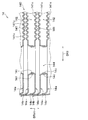
- the equipment cooler 14 is integrally formed by joining a plurality of plate-shaped members 14a in a laminated state.
- the plate-shaped member 14a is an elongated substantially rectangular plate material.
- the plate-shaped member 14a for example, a double-sided clad material in which a brazing material is clad on both sides of an aluminum core material is used.
- An overhanging portion 14b is formed on the outer peripheral edge portion of the plate-shaped member 14a so as to project in a direction substantially orthogonal to the plate surface of the plate-shaped member 14a.
- the plurality of plate-shaped members 14a are joined to each other by brazing in a state where the overhanging portions 14b are laminated with each other.
- the plurality of plate-shaped members 14a are arranged so that the protruding tips of the overhanging portions 14b are in the same direction.
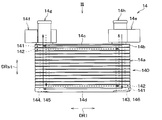
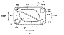
- the equipment cooler 14 includes a core unit 140 for heat exchange between a refrigerant and a low-temperature heat medium by a plurality of plate-shaped members 14a, a refrigerant distribution unit 143, a refrigerant collection unit 144, a heat medium distribution unit 145, and a heat medium collection unit. 146 is formed.
- the core unit 140 has a plurality of refrigerant flow path portions 141 through which the refrigerant flows and a plurality of heat medium flow path portions 142 through which the low temperature heat medium flows.
- the core portion 140 is a flow path laminate composed of a plurality of refrigerant flow path portions 141 and a plurality of heat medium flow path portions 142 alternately laminated.
- the plate-shaped member 14a serves as a partition wall that separates the refrigerant flow path portion 141 and the heat medium flow path portion 142.
- the heat exchange between the refrigerant flowing through the refrigerant flow path portion 141 and the low temperature heat medium flowing through the heat medium flow path portion 142 is performed via the plate-shaped member 14a.
- the core portion 140 is configured in a rectangular parallelepiped shape.
- the term "rectangular parallelepiped” does not strictly indicate only a rectangular parallelepiped, but means that the general shape as a whole is a rectangular parallelepiped even if it has some irregularly shaped portions.
- the core portion 140 has a substantially rectangular outer shape as seen from the stacking direction DRst of the plate-shaped member 14a.
- the dimension L1 in the first direction orthogonal to the stacking direction DRst of the plate-shaped member 14a is orthogonal to the stacking direction DRst and the first direction, respectively. It is larger than the dimension L2 in the second direction.
- the first direction is the longitudinal direction DRl of the refrigerant flow path portion 141.
- the second direction is the lateral DRs of the refrigerant flow path portion 141.
- the vertical direction of the paper surface in FIG. 2 corresponds to the stacking direction DRst of the plate-shaped member 14a.
- the left-right direction of the paper surface in FIG. 2 is orthogonal to the stacking direction DRst of the core portion 140 and corresponds to the longitudinal direction DRl of the refrigerant flow path portion 141.
- the depth direction of the paper surface in FIG. 2 is orthogonal to each of the stacking direction DRst of the core portion 140 and the longitudinal direction DRl of the refrigerant flow path portion 141, and corresponds to the lateral DRs of the refrigerant flow path portion 141.
- the refrigerant distribution section 143 and the heat medium collecting section 146 are formed in the core section 140 on one side of the refrigerant flow path section 141 and the heat medium flow path section 142 in the longitudinal direction DRl.
- the refrigerant collecting portion 144 and the heat medium distribution portion 145 are formed in the core portion 140 on the other side of the refrigerant flow path portion 141 and the heat medium flow path portion 142 in the longitudinal direction DRl.
- the refrigerant distribution unit 143, the refrigerant collection unit 144, the heat medium distribution unit 145, and the heat medium collection unit 146 are composed of communication holes formed at the four corners of the plate-shaped member 14a.
- the refrigerant distribution unit 143 and the refrigerant collection unit 144 are formed at two diagonal corners of the four corners of the plate-shaped member 14a. Further, the heat medium distribution section 145 and the heat medium assembly section 146 are formed in the remaining two corners.
- the refrigerant is distributed to the plurality of refrigerant flow paths 141 via the refrigerant distribution section 143. Therefore, the refrigerant distribution unit 143 constitutes the refrigerant inlet portions of the plurality of refrigerant flow path portions 141. Further, the refrigerant that has passed through the plurality of refrigerant flow path portions 141 collects in the refrigerant collecting portion 144. Therefore, the refrigerant collecting portion 144 constitutes a refrigerant outlet portion of a plurality of refrigerant flow path portions 141.
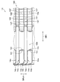
- the plurality of plate-shaped members 14a include a first end plate-shaped member 14c and a second end plate-shaped member 14d located outside the stacking direction DRst.
- An inlet connector 14e for connecting the refrigerant pipe is attached to the first end plate-shaped member 14c at the position where the refrigerant distribution portion 143 is formed, and the refrigerant pipe is provided at the position where the refrigerant collecting portion 144 is formed.
- An outlet connector 14f for connection is attached.
- the first end plate-shaped member 14c is attached with an inlet pipe 14g for connecting to the heat medium piping at a position where the heat medium distribution portion 145 is formed, and a position where the heat medium collecting portion 146 is formed.
- An outlet pipe 14h for connecting a heat medium pipe is attached to the pipe.
- the plurality of plate-shaped members 14a constituting the core portion 140 have a substantially cylindrical shape protruding toward one end side or the other end side of the stacking direction DRst at the four corners of the plate-shaped member 14a. It has a protruding portion 14i.
- the protrusion 14i forms a refrigerant distribution unit 143, a refrigerant collection unit 144, a heat medium distribution unit 145, and a heat medium collection unit 146.
- the equipment cooler 14 configured in this way has a plurality of refrigerant flow path portions 141 when the refrigerant flowing in from the inlet connector 14e side passes through the refrigerant distribution portion 143. Is distributed to. Then, the refrigerant distributed to the plurality of refrigerant flow path portions 141 flows from one side to the other side in the longitudinal direction DRl. After that, the refrigerant flowing through the plurality of refrigerant flow path portions 141 collects in the refrigerant collecting portion 144 and flows out from the outlet connector 14f side to the outside.
- the equipment cooler 14 has a plurality of heat medium flow path portions 142 when the low temperature heat medium flowing in from the inlet pipe 14 g side passes through the heat medium distribution portion 145. Will be distributed to. Then, the low-temperature heat medium distributed to the plurality of heat medium flow path portions 142 flows from the other side of the longitudinal DRl toward one side. After that, the low-temperature heat medium flowing through the plurality of heat medium flow path portions 142 collects in the heat medium collecting portion 146 and flows out from the outlet pipe 14h side to the outside.
- the device cooler 14 of the present embodiment is configured such that the flow of the refrigerant passing through the core portion 140 and the flow of the low-temperature heat medium are in opposite directions (that is, countercurrent). According to this, the temperature difference between the refrigerant and the low-temperature heat medium in the core portion 140 is maintained, so that the low-temperature heat medium easily absorbs heat into the refrigerant.
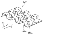
- the offset fins 147 shown in FIG. 5 are arranged between the plate-shaped members 14a.
- the offset fin 147 is an inner fin that is interposed between the plate-shaped members 14a and promotes heat exchange between the refrigerant and the low-temperature heat medium.
- the offset fin 147 is a plate-shaped member on which a partially cut-up portion 147a is formed. A large number of cut-up portions 147a are formed in the direction F1 parallel to the flow direction of the refrigerant and the low-temperature heat medium.
- cut-up portions 147a adjacent to each other in the direction F1 parallel to the flow direction of the refrigerant and the low-temperature heat medium are offset from each other.
- a large number of cut-up portions 147a are staggered in a direction F1 parallel to the flow direction of the refrigerant and the low-temperature heat medium.
- the temperature of the refrigerant becomes very low on the low pressure side in the cycle, and the refrigerant density becomes low. Therefore, the flow rate of the refrigerant passing through the air-conditioning cooler 16 and the equipment cooler 14 becomes small. In addition, on the low pressure side of the cycle, the viscosity of the oil increases as the temperature of the refrigerant decreases.
- the evaporation pressure adjusting valve 17 is connected to the outlet side of the air conditioning cooler 16 among the air conditioning cooler 16 and the equipment cooler 14. Therefore, the pressure drop on the outlet side of the air conditioning cooler 16 is limited by the evaporation pressure adjusting valve 17. On the other hand, the pressure drop on the outlet side of the equipment cooler 14 is not particularly limited.
- the lower limit temperature of the refrigerant flowing into the air conditioning cooler 16 is set to a temperature near the freezing point (for example, -1 ° C. to 1 ° C.).
- the device cooler 14 functions as a heat absorber during indoor heating, for example. Since the equipment cooler 14 absorbs heat from a low-temperature heat medium, a cryogenic refrigerant (for example, about ⁇ 10 ° C. to ⁇ 30 ° C.) may pass through the cooler 14. Such a situation occurs, for example, when the low temperature side radiator 43 becomes frosted or the outside air temperature drops to an extremely low temperature.
- a cryogenic refrigerant for example, about ⁇ 10 ° C. to ⁇ 30 ° C.
- the temperature on the outlet side of the equipment cooler 14 may be lower than the temperature on the outlet side of the air conditioning cooler 16. Therefore, in the equipment cooler 14, the flow rate of the refrigerant tends to be smaller than that in the air conditioner cooler 16, and the oil tends to stay in the equipment cooler 14 as compared with the air conditioner cooler 16.
- the equipment cooler 14 is configured so that the retention of oil is suppressed.
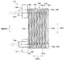
- the equipment cooler 14 is installed in a posture in which the longitudinal DRl (that is, the first direction) of the refrigerant flow path portion 141 is close to the vertical direction.
- the equipment cooler 14 is installed in a posture in which the larger the dimension of the refrigerant flow path portion 141 in the direction orthogonal to the stacking direction DRst of the core portion 140 is closer to the vertical direction.
- the equipment cooler 14 is installed in a posture in which the longitudinal DRl of the refrigerant flow path portion 141 coincides with the vertical direction.
- the equipment cooler 14 may be installed in a posture in which the longitudinal DRl of the refrigerant flow path portion 141 is slightly tilted with respect to the vertical direction.
- the refrigerant collecting portion 144 constituting the refrigerant outlet portion of the refrigerant flow path portion 141 is located closer to the lower end portion 141b of the refrigerant flow path portion 141 than the upper end portion 141a of the refrigerant flow path portion 141. Is set to.
- the refrigerant flow path portion 141 is configured so that the refrigerant flowing toward the refrigerant collecting portion 144 becomes a downflow. That is, in the refrigerant flow path portion 141, at least a flow path close to the refrigerant collecting portion 144 is positioned above the refrigerant collecting portion 144. Specifically, the refrigerant collecting portion 144 is set above the refrigerant distributing portion 143 so that most of the refrigerant flowing through the refrigerant flow path portion 141 flows down.
- the indoor air conditioning unit 60 shown in FIG. 1 is for adjusting the temperature of the blown air blown into the vehicle interior to an appropriate temperature.
- the interior air conditioning unit 60 is arranged inside the instrument panel at the front of the vehicle interior.
- the air conditioning cooler 16 and the heater core 32 are housed inside the casing 61 forming the outer shell.
- the casing 61 is a passage forming portion that forms an air flow path for blown air to be blown into the vehicle interior.
- an inside / outside air box for adjusting the introduction ratio of the inside air to the outside air introduced into the casing 61 is arranged on the upstream side of the air flow of the casing 61.
- a blower 62 for blowing the air introduced from the inside / outside air box into the vehicle interior is arranged.
- the blower 62 is composed of an electric blower that rotates a centrifugal fan with an electric motor. The rotation speed of the blower 62 is controlled according to a control signal output from the control device 80 described later.
- an air conditioner cooler 16 is arranged on the downstream side of the air flow of the blower 62. Inside the casing 61, the downstream side of the air flow of the air conditioning cooler 16 is divided into a hot air flow path 63 and a cold air flow path 64. A heater core 32 is arranged in the warm air flow path 63. The cold air flow path 64 is a flow path for allowing air that has passed through the air conditioning cooler 16 to bypass the heater core 32.
- an air mix door 65 is arranged between the air conditioning cooler 16 and the heater core 32.
- the air mix door 65 adjusts the air volume ratio of the air passing through the hot air flow path 63 and the air passing through the cold air flow path 64.
- an air mix space 66 is formed on the downstream side of the hot air flow path 63 and the cold air flow path 64 to mix the hot air passing through the hot air flow path 63 and the cold air passing through the cold air flow path 64. ing.
- a plurality of opening holes are formed inside the casing 61 at the most downstream portion of the air flow for blowing out blown air adjusted to a desired temperature in the air mix space 66 into the vehicle interior.
- the control device 80 is composed of a computer including a processor and a memory, and peripheral circuits thereof.
- the control device 80 performs various calculations and processes based on the program stored in the memory, and controls various devices connected to the output side.
- the memory of the control device 80 is composed of a non-transitional substantive storage medium.
- Various devices including the constituent devices of the refrigeration cycle device 10 are connected to the output of the control device 80. Specifically, on the output side of the control device 80, a compressor 11, a first decompression unit 13, a second decompression unit 15, a high temperature side pump 31, a high temperature side flow rate adjusting valve 34, a low temperature side pump 41, and each flow path. Switching valves 44 and 45, a blower 62, an air mix door 65 and the like are connected.
- a sensor group 81 for air conditioning control is connected to the input side of the control device 80.
- the sensor group 81 includes an inside air temperature sensor, an outside air temperature sensor, a solar radiation sensor, a PT sensor that detects the pressure and temperature on the outlet side of each of the coolers 14 and 16, and the like.
- the detection signal of the sensor group 81 is input to the control device 80.
- the refrigeration cycle device 10 can adjust the temperature of the blown air blown into the vehicle interior according to the physical quantity detected by the sensor group 81, and can realize comfortable air conditioning.
- An operation panel 82 used for various input operations is connected to the input side of the control device 80.
- the operation panel 82 is arranged near the instrument panel and has various operation switches. Operation signals from various operation switches provided on the operation panel 82 are input to the control device 80.
- the various operation switches on the operation panel 82 include an auto switch, an operation mode changeover switch, an air volume setting switch, a temperature setting switch, a blowout mode changeover switch, and the like.
- the refrigeration cycle device 10 can appropriately switch the operation mode of the refrigeration cycle device 10 by receiving the input from the operation panel 82.
- the air conditioner 1 is configured to be capable of executing indoor cooling, equipment cooling, and indoor heating as operation modes. Therefore, in the present embodiment, the operation of the air conditioner 1 will be described for each of the indoor cooling, the equipment cooling, and the indoor heating.
- the indoor cooling is an operation mode in which the air cooled to a desired temperature by the indoor air conditioning unit 60 is blown into the vehicle interior.
- the control device 80 appropriately determines the operating state of various devices during indoor cooling by using the detection signal of the sensor group 81 and the operation signal of the operation panel 82.
- each pressure reducing unit is such that the first on-off valve 131 is fully closed, the second on-off valve 151 is fully opened, and the throttle opening of the second expansion valve 152 is a predetermined opening. 13 and 15 are controlled.
- the predetermined opening degree during indoor cooling is set to, for example, an opening degree at which the refrigerant state on the outlet side of the air conditioner cooler 16 becomes a superheated state having a degree of superheat.
- control device 80 controls the high temperature side flow rate adjusting valve 34 so that the entire amount of the high temperature heat medium passing through the radiator 12 flows to the high temperature side radiator 33. Further, the control device 80 controls the air mix door 65 at a position where the hot air flow path 63 is fully closed and the cold air flow path 64 is fully opened. The control device 80 appropriately determines the control signals for other devices by using the detection signals of the sensor group 81 and the operation signals of the operation panel 82.
- the high-pressure refrigerant discharged from the compressor 11 flows into the condensing portion 121 of the radiator 12.
- the refrigerant flowing into the condensing unit 121 dissipates heat to the high-temperature heat medium flowing through the high-temperature heat medium circuit 30 and condenses.
- the high-temperature heat medium flowing through the high-temperature heat medium circuit 30 is heated to raise the temperature.
- the high-temperature heat medium heated by the condensing unit 121 flows to the high-temperature side radiator 33 and is dissipated to the outside air. That is, during indoor cooling, the high-pressure refrigerant in the cycle is dissipated to the outside air via the high-temperature heat medium.
- the refrigerant that has passed through the condensing section 121 flows into the receiving section 122 and gas and liquid are separated. Then, the liquid refrigerant separated by the liquid receiving unit 122 flows into the supercooling unit 123. The refrigerant that has flowed into the supercooling unit 123 dissipates heat to the high-temperature heat medium flowing through the high-temperature heat medium circuit 30 and is supercooled.
- the refrigerant flowing out of the supercooling unit 123 flows into the second decompression unit 15 and is depressurized by the second expansion valve 152 of the second decompression unit 15. Since the first on-off valve 131 is fully closed during indoor cooling, the refrigerant does not flow into the first expansion valve 132, and the entire amount of the refrigerant is depressurized by the second decompression unit 15.
- the refrigerant decompressed by the second decompression unit 15 flows into the air conditioning cooler 16.
- the refrigerant that has flowed into the air conditioning cooler 16 absorbs heat from the air blown from the blower 62 and evaporates. As a result, the blown air from the blower 62 is cooled.
- the refrigerant that has passed through the air conditioning cooler 16 is sucked into the compressor 11 via the evaporation pressure adjusting valve 17.
- the refrigerant sucked into the compressor 11 is compressed by the compressor 11 until it becomes a high-pressure refrigerant again.
- the interior of the vehicle can be cooled by blowing out the blown air cooled by the air conditioner cooler 16 into the vehicle interior.
- the equipment cooling is an operation mode in which the battery BT, which is a heat generating equipment, is cooled by utilizing the latent heat of vaporization of the refrigerant.
- the control device 80 appropriately determines the operating state of various devices when the devices are cooled by using the detection signal of the sensor group 81 and the operation signal of the operation panel 82.
- each pressure reducing unit is such that the second on-off valve 151 is fully closed, the first on-off valve 131 is fully opened, and the throttle opening of the first expansion valve 132 is a predetermined opening. 13 and 15 are controlled.
- the predetermined opening degree at the time of cooling the equipment is set to, for example, an opening degree at which the refrigerant state on the outlet side of the equipment cooler 14 becomes a superheated state having a degree of superheat.
- control device 80 controls the high temperature side flow rate adjusting valve 34 so that the entire amount of the high temperature heat medium passing through the radiator 12 flows to the high temperature side radiator 33. Further, in the control device 80, the first flow path switching valve 44 is fully opened and the second flow path switching valve 45 is opened so that the entire amount of the low temperature heat medium passing through the device cooler 14 flows to the battery cooling unit 42. Control so that it is in a fully closed state.
- the control device 80 appropriately determines the control signals for other devices by using the detection signals of the sensor group 81 and the operation signals of the operation panel 82.
- the high-pressure refrigerant discharged from the compressor 11 flows into the condensing portion 121 of the radiator 12 in the refrigeration cycle device 10.
- the refrigerant flowing into the condensing unit 121 dissipates heat to the high-temperature heat medium flowing through the high-temperature heat medium circuit 30 and condenses. As a result, the high-temperature heat medium flowing through the high-temperature heat medium circuit 30 is heated to raise the temperature.
- the high-temperature heat medium heated by the condensing unit 121 flows to the high-temperature side radiator 33 and is dissipated to the outside air. That is, when the equipment is cooled, the high-pressure refrigerant in the cycle is dissipated to the outside air via the high-temperature heat medium.
- the refrigerant that has passed through the condensing section 121 flows into the receiving section 122 and gas and liquid are separated. Then, the liquid refrigerant separated by the liquid receiving unit 122 flows into the supercooling unit 123. The refrigerant that has flowed into the supercooling unit 123 dissipates heat to the high-temperature heat medium flowing through the high-temperature heat medium circuit 30 and is supercooled.
- the refrigerant flowing out of the supercooling unit 123 flows into the first decompression unit 13 and is depressurized by the first expansion valve 132 of the first decompression unit 13. Since the second on-off valve 151 is fully closed when the equipment is cooled, the refrigerant does not flow into the second expansion valve 152, and the entire amount of the refrigerant is depressurized by the first decompression unit 13.
- the refrigerant decompressed by the first decompression unit 13 flows into the equipment cooler 14.
- the refrigerant flowing into the equipment cooler 14 absorbs heat from the low-temperature heat medium flowing through the low-temperature heat medium circuit 40 and evaporates. As a result, the low temperature heat medium is cooled.
- the refrigerant that has passed through the equipment cooler 14 is sucked into the compressor 11.
- the refrigerant sucked into the compressor 11 is compressed by the compressor 11 until it becomes a high-pressure refrigerant again.
- the low-temperature heat medium cooled by the device cooler 14 flows to the battery cooling unit 42 and absorbs heat from the battery BT.
- the battery BT is cooled. That is, when the equipment is cooled, the battery BT is cooled by utilizing the latent heat of vaporization of the refrigerant in the equipment cooler 14.
- the battery BT when the equipment is cooled, the battery BT can be cooled by supplying the low temperature heat medium cooled by the equipment cooler 14 to the battery cooling unit 42.
- the high temperature side flow rate adjusting valve 34 is controlled so that the entire amount of the high temperature heat medium passing through the radiator 12 flows to the high temperature side radiator 33, but the present invention is not limited to this. ..
- the high temperature side flow rate adjusting valve 34 may be controlled by the control device 80 so that the high temperature heat medium passing through the radiator 12 flows to the heater core 32. According to this, it becomes possible to carry out equipment cooling and room heating at the same time.
- the second on-off valve 151 is fully closed, the first on-off valve 131 is fully opened, and the throttle opening of the first expansion valve 132 is reduced to a predetermined opening degree.
- Examples of those in which parts 13 and 15 are controlled are illustrated, but the present invention is not limited to this.
- the control device 80 controls the second pressure reducing unit 15 so that the second on-off valve 151 is fully opened and the throttle opening of the second expansion valve 152 is a predetermined opening. May be controlled. According to this, it becomes possible to carry out equipment cooling and indoor cooling at the same time.
- the indoor heating is an operation mode in which the air heated to a desired temperature by the indoor air conditioning unit 60 is blown into the vehicle interior.
- the control device 80 appropriately determines the operating state of various devices during indoor heating by using the detection signal of the sensor group 81 and the operation signal of the operation panel 82.
- each pressure reducing unit is such that the second on-off valve 151 is fully closed, the first on-off valve 131 is fully opened, and the throttle opening of the first expansion valve 132 is a predetermined opening. 13 and 15 are controlled.
- the predetermined opening during indoor heating is set to an opening suitable for indoor heating.
- control device 80 controls the high temperature side flow rate adjusting valve 34 so that the entire amount of the high temperature heat medium passing through the radiator 12 flows to the heater core 32. Further, the control device 80 controls the first flow path switching valve 44 and the second flow path switching valve 45 so that the entire amount of the low temperature heat medium passing through the equipment cooler 14 flows to the low temperature side radiator 43. That is, the control device 80 controls so that the first flow path switching valve 44 is in the fully closed state and the second flow path switching valve 45 is in the fully open state.
- the control device 80 controls the air mix door 65 at a position where the cold air flow path 64 is fully closed and the hot air flow path 63 is fully opened.
- the control device 80 appropriately determines the control signals for other devices by using the detection signals of the sensor group 81 and the operation signals of the operation panel 82.
- the high-pressure refrigerant discharged from the compressor 11 flows into the condensing portion 121 of the radiator 12.
- the refrigerant flowing into the condensing unit 121 dissipates heat to the high-temperature heat medium flowing through the high-temperature heat medium circuit 30 and condenses.
- the high-temperature heat medium flowing through the high-temperature heat medium circuit 30 is heated to raise the temperature.
- the high-temperature heat medium heated by the condensing unit 121 flows to the heater core 32 and is dissipated to the blown air blown into the vehicle interior. That is, during indoor heating, the high-pressure refrigerant in the cycle is dissipated to the blown air that blows into the vehicle interior via the high-temperature heat medium.
- the refrigerant that has passed through the condensing section 121 flows into the receiving section 122 and gas and liquid are separated. Then, the liquid refrigerant separated by the liquid receiving unit 122 flows into the supercooling unit 123. The refrigerant that has flowed into the supercooling unit 123 dissipates heat to the high-temperature heat medium flowing through the high-temperature heat medium circuit 30 and is supercooled.
- the refrigerant flowing out of the supercooling unit 123 flows into the first decompression unit 13 and is depressurized by the first expansion valve 132 of the first decompression unit 13. Since the second on-off valve 151 is fully closed during indoor heating, the refrigerant does not flow into the second expansion valve 152, and the entire amount of the refrigerant is depressurized by the first decompression unit 13.
- the refrigerant decompressed by the first decompression unit 13 flows into the equipment cooler 14.
- the refrigerant flowing into the equipment cooler 14 absorbs heat from the low-temperature heat medium flowing through the low-temperature heat medium circuit 40 and evaporates. As a result, the low temperature heat medium is cooled.
- the low-temperature heat medium cooled by the equipment cooler 14 flows to the low-temperature side radiator 43 and absorbs heat from the outside air.
- the refrigerant that has passed through the equipment cooler 14 is sucked into the compressor 11.
- the refrigerant sucked into the compressor 11 is compressed by the compressor 11 until it becomes a high-pressure refrigerant again.
- the interior of the vehicle can be heated by blowing out the blown air heated by the heater core 32 into the vehicle interior.
- the first flow path switching valve 44 is controlled to be in a fully closed state so that the low temperature heat medium does not pass through the battery cooling unit 42 during the above-mentioned indoor heating, but the present invention is not limited to this.
- the first flow path switching valve 44 may be controlled to the fully open state by the control device 80 so that the low temperature heat medium passes through the battery cooling unit 42.
- the exhaust heat of the battery BT can be absorbed by the refrigerant in the device cooler 14 via the low temperature heat medium. Therefore, it can be used as a heat source for heating the blown air that blows the exhaust heat of the battery BT into the vehicle interior.
- the equipment cooler 14 functions as an endothermic during indoor heating. Since the device cooler 14 absorbs heat from the outside air through a low-temperature heat medium, a cryogenic refrigerant (for example, about ⁇ 10 ° C. to ⁇ 30 ° C.) may pass through the cooler 14. In this case, the flow rate of the refrigerant decreases and the viscosity of the oil increases, so that the oil tends to stay in the equipment cooler 14.
- a cryogenic refrigerant for example, about ⁇ 10 ° C. to ⁇ 30 ° C.
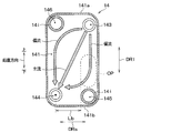
- FIG. 7 shows the refrigerant flow path portion 141 when the equipment cooler 14 is installed horizontally.
- FIG. 7 shows the refrigerant flow path portion 141 when the equipment cooler 14 is installed in a direction in which the lateral DRs of the refrigerant flow path portion 141 coincide with the vertical direction.
- the gas-liquid two-phase refrigerant that has flowed from the refrigerant distribution section 143 into the refrigerant flow path section 141 flows toward the refrigerant collecting section 144.
- the liquid refrigerant passing through the refrigerant flow path portion 141 absorbs heat from the low-temperature heat medium and evaporates. Then, when the liquid refrigerant evaporates, the oil is separated from the refrigerant. A part of the oil separated from the refrigerant falls to the lower side of the refrigerant flow path portion 141 due to gravity. As a result, an oil retention portion OP in which oil stays is formed on the lower side of the refrigerant flow path portion 141. The oil retention portion OP is likely to be formed below the refrigerant distribution portion 143.
- FIG. 8 shows the refrigerant flow path portion 141 when the equipment cooler 14 is installed vertically. That is, FIG. 8 shows the refrigerant flow path portion 141 in the installed state of the equipment cooler 14 of the present embodiment.
- an oil retention portion OP is formed on the lower side of the refrigerant flow path portion 141.
- the DRl in the longitudinal direction of the refrigerant flow path portion 141 is in a state close to the vertical direction, so that the oil retention portion OP becomes vertically long. That is, it is suppressed that the oil is unevenly distributed in the vicinity of the lower end portion 141b in the refrigerant flow path portion 141.
- the distance Lb from the oil retention portion OP to the refrigerant collecting portion 144 is small, so that the oil retention is easily eliminated.
- the device cooler 14 is configured so that oil retention is suppressed.
- the equipment cooler 14 is installed in a posture in which the longitudinal DRl (that is, the first direction) of the refrigerant flow path portion 141 is close to the vertical direction.
- the oil is likely to be distributed vertically instead of horizontally in the refrigerant flow path portion 141 of the equipment cooler 14. That is, it is suppressed that the oil is unevenly distributed in the vicinity of the lower end portion 141b in the refrigerant flow path portion 141 of the equipment cooler 14.
- the equipment cooler 14 has a structure in which oil is easily distributed vertically in the refrigerant flow path portion 141, and the refrigerant collecting portion 144 is set at a position closer to the lower end portion 141b than the upper end portion 141a of the refrigerant flow path portion 141. Has been done. According to this, the oil existing in the refrigerant flow path portion 141 is likely to collect in the refrigerant collecting portion 144, so that the retention of oil in the equipment cooler 14 can be suppressed.
- the refrigerant flow path portion 141 of the equipment cooler 14 is configured so that the refrigerant flowing toward the refrigerant collecting portion 144 becomes a downflow.
- the refrigerant collecting unit 144 is set above the refrigerant distribution unit 143. According to this, the oil existing in the refrigerant flow path portion 141 is easily washed away to the refrigerant collecting portion 144 side by the flow of the refrigerant falling due to gravity, so that the retention of oil in the equipment cooler 14 can be suppressed. ..
- the radiator 12 has a liquid receiving unit 122, and the outlet side of the equipment cooler 14 and the air conditioning cooler 16 is connected to the refrigerant suction side of the compressor 11.
- the configuration in which the liquid receiving portion 122 is provided on the high pressure side in the cycle is a configuration in which the liquid receiving portion is provided on the outlet side of the equipment cooler 14 and the air conditioning cooler 16, as compared with the configuration in which the liquid receiving unit 122 is provided. It becomes easy to exhibit the heat exchange performance of 14. Therefore, according to this configuration, the heat exchange performance of the equipment cooler 14 can be appropriately exhibited while suppressing the retention of oil in the equipment cooler 14.
- evaporation is performed to maintain the pressure of the refrigerant on the outlet side of the air conditioner cooler 16 at a pressure higher than the pressure of the refrigerant on the outlet side of the equipment cooler 14.
- a pressure regulating valve 17 is arranged. According to this, when the refrigerant flows through both the air conditioner cooler 16 and the equipment cooler 14, the refrigerant flowing through the air conditioner cooler 16 and the equipment cooler 14 can be adjusted to a temperature suitable for each. It becomes.
- an offset fin 147 is arranged inside, but the present invention is not limited to this.
- the device cooler 14 may have inner fins other than the offset fins 147 arranged inside.
- the corrugated fin 148 shown in FIG. 9 can be adopted.
- the corrugated fin 148 is a fin bent in a wavy shape.
- the corrugated fin 148 of this example has a slit-shaped louver 148a formed on the plate surface.
- the corrugated fin 148 does not have to have the louver 148a formed on the plate surface.
- the device cooler 14 of the present embodiment has the same configuration as that of the first embodiment. Therefore, the action and effect produced from the same configuration as that of the first embodiment can be obtained as in the first embodiment.
- the refrigeration cycle device 10A of the present disclosure is applied to the device cooling system for cooling the battery BT, which is a heat generating device, will be described.
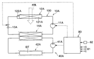
- the refrigeration cycle device 10A shown in FIG. 11 can perform equipment cooling for cooling the battery BT.
- the refrigeration cycle device 10A includes a compressor 11A, a radiator 12A, a decompression unit 13A, a device cooler 14A, and a control device 80.
- a compressor 11A, a radiator 12A, a decompression unit 13A, and an equipment cooler 14A are arranged in this order. Since the compressor 11A and the device cooler 14A are configured in the same manner as the compressor 11 and the device cooler 14 described in the first embodiment, the description thereof will be omitted.
- the radiator 12A dissipates the refrigerant discharged from the compressor 11.
- the radiator 12A is a heat exchanger that dissipates the high-pressure refrigerant discharged from the compressor 11 to the outside air, which is the first heat medium.
- the radiator 12A is arranged on the front side of the vehicle to which the running wind hits when the vehicle is running.
- the radiator 12A has a condensing unit 121A that condenses the refrigerant, and a liquid receiving unit 122A that separates the gas and liquid of the refrigerant that has passed through the condensing unit 121A and stores the liquid refrigerant that becomes surplus in the cycle. ..
- the condensing unit 121A is composed of, for example, a fin-and-tube type heat exchanger in which a plurality of tubes are connected by outer fins.
- the liquid receiving unit 122A is configured in the same manner as the liquid receiving unit 122 described in the first embodiment.
- a decompression unit 13A is connected to the outlet side of the radiator 12.
- the pressure reducing unit 13A is an expansion valve that reduces the pressure of the refrigerant that has passed through the radiator 12.
- the pressure reducing unit 13A is composed of an electric expansion valve having a valve body and an electric actuator.
- the valve body is configured so that the throttle opening, which is the opening of the refrigerant flow path, can be changed.
- the electric actuator includes a stepping motor that displaces the valve body to change the throttle opening degree of the decompression unit 13A.
- the pressure reducing unit 13A controls the throttle opening degree according to the control signal from the control device 80.
- the equipment cooler 14A is a chiller that evaporates the refrigerant by exchanging heat with the low temperature heat medium circulating in the low temperature heat medium circuit 40A from the refrigerant decompressed by the decompression unit 13A.
- the equipment cooler 14A is an endothermic device that absorbs heat from the low-temperature heat medium by exchanging heat with the low-temperature heat medium that is the second heat medium, with the refrigerant decompressed by the decompression unit 13A.
- the low temperature heat medium circuit 40A is a circuit that circulates the low temperature heat medium.
- a device cooler 14A a low temperature side pump 41A, a battery cooling unit 42A, and the like are arranged.
- the low temperature side pump 41A and the battery cooling unit 42A are configured in the same manner as the low temperature side pump 41A and the battery cooling unit 42A described in the first embodiment.
- the equipment cooling system configured in this way cools the battery BT, which is a heat generating equipment, by utilizing the latent heat of vaporization of the refrigerant in the refrigeration cycle device 10.
- the control device 80 appropriately determines the operating state of various devices by using the detection signal of the sensor group 81 and the operation signal of the operation panel 82 when the device is cooled to cool the battery BT.
- the control device 80 controls so that the throttle opening degree of the decompression unit 13A becomes a predetermined opening degree.
- the predetermined opening degree is set to, for example, an opening degree in which the refrigerant state on the outlet side of the equipment cooler 14A becomes a superheated state having a superheat degree.
- the high-pressure refrigerant discharged from the compressor 11A flows into the condensing portion 121A of the radiator 12A.
- the refrigerant that has flowed into the condensing section 121A dissipates heat to the outside air and condenses.
- the refrigerant that has passed through the condensing portion 121A flows into the liquid receiving portion 122A, and gas and liquid are separated. Then, the liquid refrigerant separated by the liquid receiving unit 122A flows into the decompression unit 13A, and the pressure is reduced by the decompression unit 13A.
- the refrigerant decompressed by the decompression unit 13A flows into the equipment cooler 14A.
- the refrigerant that has flowed into the equipment cooler 14A absorbs heat from the low-temperature heat medium flowing through the low-temperature heat medium circuit 40A and evaporates. As a result, the low temperature heat medium is cooled.
- the refrigerant that has passed through the equipment cooler 14A is sucked into the compressor 11A.
- the refrigerant sucked into the compressor 11A is compressed by the compressor 11A until it becomes a high-pressure refrigerant again.
- the low-temperature heat medium cooled by the device cooler 14A flows to the battery cooling unit 42A and absorbs heat from the battery BT.
- the battery BT is cooled. That is, when the equipment is cooled, the battery BT is cooled by utilizing the latent heat of vaporization of the refrigerant in the equipment cooler 14A.
- the equipment cooling system can cool the battery BT by supplying the low temperature heat medium cooled by the equipment cooler 14A to the battery cooling unit 42A at the time of equipment cooling.
- the refrigeration cycle device 10A of the present embodiment has the same configuration as that of the first embodiment. Therefore, the action and effect produced from the same configuration as that of the first embodiment can be obtained as in the first embodiment.
- the refrigeration cycle device 10 an example capable of performing indoor cooling, equipment cooling, and indoor heating is exemplified, but the present invention is not limited to this.
- the refrigeration cycle device 10 may be configured to enable only indoor cooling and indoor heating, for example. Further, the refrigeration cycle device 10 may be configured to be capable of performing dehumidification and heating in the vehicle interior.
- Each configuration of the refrigeration cycle apparatus 10 described in the above-described embodiment is not limited to the one disclosed in the above-described embodiment.
- the compressor 11 for example, one driven by an internal combustion engine may be adopted.
- the radiator 12 may have a configuration in which, for example, the liquid receiving unit 122 and the supercooling unit 123 are omitted, and only the condensing unit 121 is provided.
- At least one of the first expansion valve 132, the second expansion valve 152, and the pressure reducing portion 13A may be composed of, for example, a mechanical expansion valve or a fixed throttle.
- the first on-off valve 131 and the second on-off valve 151 may be arranged, for example, on the downstream side of the first expansion valve 132 and the second expansion valve 152.
- first decompression unit 13 and the second decompression unit 15 may be composed of an electric expansion valve having a fully closed function.
- the evaporation pressure adjusting valve 17 may be arranged not in the third refrigerant flow path 100c but in the second refrigerant flow path 100b, for example.
- the refrigerant flow path portion 141 and the heat medium flow path portion 142 are alternately laminated one by one in the stacking direction DRst, but the present invention is not limited to this. ..
- a plurality of refrigerant flow path portions 141 and heat medium flow path portions 142 may be alternately laminated in the stacking direction DRst.
- the device cooler 14 is configured to include the refrigerant flow path portion 141 in which the flow of the refrigerant does not make a U-turn, but the present invention is not limited to this.
- the equipment cooler 14 may be configured to include, for example, a refrigerant flow path portion 141 in which the flow of the refrigerant makes a U-turn. It is desirable that the equipment cooler 14 is installed so that when the refrigerant flow path 141 makes a U-turn, at least the flow toward the refrigerant collecting section 144 becomes a down flow.
- the flow of the refrigerant and the flow of the low-temperature heat medium are in opposite directions (that is, countercurrent), but the present invention is not limited to this.
- the flow of the refrigerant and the flow of the low-temperature heat medium may be in the same direction (that is, parallel flow).
- examples of the device cooler 14 include those provided with inner fins and those in which a part of the plate-shaped member 14a is formed in a wavy shape, but the present invention is not limited to this.
- the device cooler 14 may have, for example, a configuration in which there are no inner fins and a part of the plate-shaped member 14a is formed in a wavy shape.
- the refrigerant flow path portion 141 of the equipment cooler 14 is preferably configured such that the refrigerant flowing toward the refrigerant collecting portion 144 is down-flowed, but the present invention is not limited to this.
- the refrigerant flow path portion 141 of the equipment cooler 14 may be configured so that the refrigerant flowing toward the refrigerant collecting portion 144 does not flow down.
- the refrigerant flow path portion 141 of the equipment cooler 14 has the refrigerant distribution portion 143 set above the refrigerant collecting portion 144.
- the refrigerant distribution portion 143 and the refrigerant collecting portion 144 may be set at similar positions.
- the present invention is not limited to this.
- a gas may be adopted as long as it has excellent thermal conductivity.
- the high-temperature heat medium circuit 30 is configured such that, for example, the flow rate ratio of the refrigerant flowing through the heater core 32 and the high-temperature side radiator 33 is adjusted by two flow rate adjusting valves provided corresponding to the heater core 32 and the high-temperature side radiator 33, respectively. You may be.
- the low temperature heat medium circuit 40 may be configured such that the flow path is switched by a three-way valve type flow path switching valve.
- the device to be cooled by the low-temperature heat medium flowing through the low-temperature heat medium circuit 40 may be a device other than the battery BT as long as it is a heat-generating device that generates heat during operation.
- the on-board heating equipment includes an electric motor that outputs driving force for running, an inverter that converts the frequency of the electric power supplied to the electric motor, and a charger for charging the battery BT.
- the low temperature heat medium circuit 40 may be configured to cool not only the battery BT but also the electric motor, the inverter, the charger, and the like. Such a configuration can be realized by connecting various heat generating devices in parallel or in series with respect to the flow of the low temperature heat medium.
- the relationship between the high temperature side radiator 33 and the low temperature side radiator 43 is not mentioned, but the high temperature side radiator 33 and the low temperature side radiator 43 are not limited to independent configurations.
- the heat of the high temperature heat medium and the heat of the low temperature heat medium may be integrated with each other so as to be heat transferable.
- the heat media may be integrated so as to be heat transferable by sharing some components (for example, heat exchange fins) of the high temperature side radiator 33 and the low temperature side radiator 43.
- the refrigeration cycle device 10 is applied to the air conditioner 1 and the equipment cooling system of the hybrid vehicle, but the present invention is not limited to this.
- the refrigeration cycle device 10 can be applied to, for example, an air conditioner 1 of an electric vehicle or an equipment cooling system. Further, the refrigeration cycle device 10 can be applied to a stationary device or system instead of a moving body such as a vehicle.
- the sensor when it is described that the external environment information of the vehicle (for example, the outside air temperature) is acquired from the sensor, the sensor is abolished and the external environment information is received from the server or the cloud outside the vehicle. It is also possible. Alternatively, it is possible to abolish the sensor, acquire related information related to the external environment information from a server or cloud outside the vehicle, and estimate the external environment information from the acquired related information.
- the external environment information of the vehicle for example, the outside air temperature
- the controls and techniques described herein are implemented by a dedicated computer provided by configuring a processor and memory programmed to perform one or more functions embodied by a computer program. May be done.
- the control device and method thereof described in the present disclosure may be realized by a dedicated computer provided by configuring a processor with one or more dedicated hardware logic circuits.
- the control device and method thereof described in the present disclosure may be a combination of a processor and memory programmed to perform one or more functions and a processor composed of one or more hardware logic circuits. It may be realized by one or more dedicated computers configured.
- the computer program may be stored in a computer-readable non-transitional real storage medium as an instruction executed by the computer.
- the heat exchanger includes a plurality of refrigerant flow paths through which the refrigerant flows and a plurality of heat medium flow paths through which the heat medium flows.
- a flow path laminate composed of alternately laminated.
- the flow path laminate is installed in a posture in which the larger the size of the refrigerant flow path portion in the direction orthogonal to the stacking direction is closer to the vertical direction.
- the refrigerant outlet portion of the refrigerant flow path portion is set at a position closer to the lower end portion of the refrigerant flow path portion than the upper end portion of the refrigerant flow path portion.
- the refrigerant flow path portion of the heat exchanger is configured so that the refrigerant flowing toward the refrigerant outlet portion becomes a downflow.
- the oil existing in the refrigerant flow path portion is easily swept toward the refrigerant outlet portion side by the flow of the refrigerant falling due to gravity, so that the retention of oil in the heat exchanger can be suppressed.
- the "downflow" includes not only a downward flow flowing along the direction of gravity but also a flow containing a downward component.
- the refrigerant inlet portion is set on the upper side of the refrigerant outlet portion. According to this, the oil existing in the refrigerant flow path portion may be easily swept toward the refrigerant outlet portion side by the flow of the refrigerant falling due to gravity, so that the oil retention in the heat exchanger can be suppressed.
- the refrigeration cycle device includes a compressor, a radiator, a decompression unit, and a heat absorber.
- the heat absorber has a flow path laminate formed by alternately laminating a plurality of refrigerant flow path portions through which a refrigerant flows and a plurality of heat medium flow path portions through which a heat medium flows.
- the flow path laminate is installed in a posture in which the larger the size of the refrigerant flow path portion in the direction orthogonal to the stacking direction is closer to the vertical direction.
- the refrigerant outlet portion of the refrigerant flow path portion is set at a position closer to the lower end portion of the refrigerant flow path portion than the upper end portion of the refrigerant flow path portion.
- the radiator has a condensing part for condensing the refrigerant, a gas-liquid part for the refrigerant passing through the condensing part, and a receiving part for storing the excess liquid refrigerant in the cycle.
- the outlet side of the refrigerant of the heat absorber is connected to the refrigerant suction side of the compressor.
- the configuration in which the liquid receiving portion is provided on the high pressure side in the cycle (so-called receiver cycle) has a heat exchange performance of the heat exchanger as compared with the configuration in which the liquid receiving portion is provided on the outlet side of the heat absorber (so-called accumulator cycle). It becomes easier to demonstrate. Therefore, according to this viewpoint, it is possible to appropriately exhibit the heat exchange performance of the heat exchanger while suppressing the retention of oil in the heat absorber.
- the heat exchange performance of the heat exchanger is lower than that in the receiver cycle because a loss occurs on the refrigerant suction side of the compressor due to the liquid receiving portion.
- the refrigeration cycle apparatus includes a compressor, a radiator, a first decompression unit, a second decompression unit, a device cooler, and an air conditioner cooler.
- the equipment cooler has a flow path laminate formed by alternately laminating a plurality of refrigerant flow path portions through which a refrigerant flows and a plurality of heat medium flow path portions through which a heat medium flows.
- the flow path laminate is installed in a posture in which the larger the size of the refrigerant flow path portion in the direction orthogonal to the stacking direction is closer to the vertical direction.
- the refrigerant outlet portion of the refrigerant flow path portion is set at a position closer to the lower end portion of the refrigerant flow path portion than the upper end portion of the refrigerant flow path portion.
- the radiator has a condensing part that condenses the refrigerant, a liquid-liquid part of the refrigerant that has passed through the condensing part, and a receiving part that stores the excess liquid refrigerant in the cycle.
- the outlet portion of the refrigerant is connected to the refrigerant suction side of the compressor.
- the configuration in which the liquid receiving portion is provided on the high pressure side in the cycle has a heat exchange performance of the equipment cooler as compared with the configuration in which the liquid receiving portion is provided on the outlet side of the equipment cooler and the air conditioning cooler. It becomes easier to exert. Therefore, according to this viewpoint, it is possible to appropriately exhibit the heat exchange performance of the equipment cooler while suppressing the retention of oil in the equipment cooler.
- the pressure of the refrigerant on the outlet side of the air conditioner cooler is maintained at a pressure higher than the pressure of the refrigerant on the outlet side of the equipment cooler on the downstream side of the refrigerant flow of the air conditioner cooler.
- a pressure regulating valve for this is arranged. According to this, when the refrigerant flows through both the air-conditioning cooler and the equipment cooler, the refrigerant flowing through the air-conditioning cooler and the equipment cooler can be adjusted to a temperature suitable for each.
Landscapes
- Engineering & Computer Science (AREA)
- Physics & Mathematics (AREA)
- Thermal Sciences (AREA)
- Mechanical Engineering (AREA)
- General Engineering & Computer Science (AREA)
- Air-Conditioning For Vehicles (AREA)
- Details Of Heat-Exchange And Heat-Transfer (AREA)
- Heat-Exchange Devices With Radiators And Conduit Assemblies (AREA)
Applications Claiming Priority (2)
| Application Number | Priority Date | Filing Date | Title |
|---|---|---|---|
| JP2019106420A JP7388007B2 (ja) | 2019-06-06 | 2019-06-06 | 熱交換器、冷凍サイクル装置 |
| JP2019-106420 | 2019-06-06 |
Publications (1)
| Publication Number | Publication Date |
|---|---|
| WO2020246337A1 true WO2020246337A1 (ja) | 2020-12-10 |
Family
ID=73652111
Family Applications (1)
| Application Number | Title | Priority Date | Filing Date |
|---|---|---|---|
| PCT/JP2020/020920 Ceased WO2020246337A1 (ja) | 2019-06-06 | 2020-05-27 | 熱交換器、冷凍サイクル装置 |
Country Status (2)
| Country | Link |
|---|---|
| JP (1) | JP7388007B2 (cg-RX-API-DMAC7.html) |
| WO (1) | WO2020246337A1 (cg-RX-API-DMAC7.html) |
Cited By (1)
| Publication number | Priority date | Publication date | Assignee | Title |
|---|---|---|---|---|
| CN114234699A (zh) * | 2021-12-13 | 2022-03-25 | 浙江银轮新能源热管理系统有限公司 | 芯片单元、芯体及冷却器 |
Families Citing this family (1)
| Publication number | Priority date | Publication date | Assignee | Title |
|---|---|---|---|---|
| JP2025095552A (ja) * | 2023-12-15 | 2025-06-26 | マレリ株式会社 | フィン、熱交換器、及び熱交換器の製造方法 |
Citations (4)
| Publication number | Priority date | Publication date | Assignee | Title |
|---|---|---|---|---|
| JP2010127508A (ja) * | 2008-11-26 | 2010-06-10 | Calsonic Kansei Corp | 複合熱交換器 |
| JP2011247579A (ja) * | 2011-08-08 | 2011-12-08 | Mitsubishi Electric Corp | プレート式熱交換器及び冷凍空調装置 |
| JP2013221629A (ja) * | 2012-04-12 | 2013-10-28 | Mitsubishi Electric Corp | プレート式熱交換器およびその製造方法並びにヒートポンプ装置 |
| WO2019065013A1 (ja) * | 2017-09-28 | 2019-04-04 | 株式会社デンソー | 冷凍サイクル装置 |
Family Cites Families (2)
| Publication number | Priority date | Publication date | Assignee | Title |
|---|---|---|---|---|
| JP2000346568A (ja) | 1999-05-31 | 2000-12-15 | Mitsubishi Heavy Ind Ltd | 熱交換器 |
| KR20080090121A (ko) * | 2007-04-04 | 2008-10-08 | 엘지전자 주식회사 | 판형 열교환기 |
-
2019
- 2019-06-06 JP JP2019106420A patent/JP7388007B2/ja active Active
-
2020
- 2020-05-27 WO PCT/JP2020/020920 patent/WO2020246337A1/ja not_active Ceased
Patent Citations (4)
| Publication number | Priority date | Publication date | Assignee | Title |
|---|---|---|---|---|
| JP2010127508A (ja) * | 2008-11-26 | 2010-06-10 | Calsonic Kansei Corp | 複合熱交換器 |
| JP2011247579A (ja) * | 2011-08-08 | 2011-12-08 | Mitsubishi Electric Corp | プレート式熱交換器及び冷凍空調装置 |
| JP2013221629A (ja) * | 2012-04-12 | 2013-10-28 | Mitsubishi Electric Corp | プレート式熱交換器およびその製造方法並びにヒートポンプ装置 |
| WO2019065013A1 (ja) * | 2017-09-28 | 2019-04-04 | 株式会社デンソー | 冷凍サイクル装置 |
Cited By (1)
| Publication number | Priority date | Publication date | Assignee | Title |
|---|---|---|---|---|
| CN114234699A (zh) * | 2021-12-13 | 2022-03-25 | 浙江银轮新能源热管理系统有限公司 | 芯片单元、芯体及冷却器 |
Also Published As
| Publication number | Publication date |
|---|---|
| JP7388007B2 (ja) | 2023-11-29 |
| JP2020200972A (ja) | 2020-12-17 |
Similar Documents
| Publication | Publication Date | Title |
|---|---|---|
| JP5626194B2 (ja) | 熱交換システム | |
| CN104781627B (zh) | 热交换器 | |
| JP5373841B2 (ja) | 冷却装置 | |
| CN102470726B (zh) | 车辆用空调装置 | |
| CN113227673B (zh) | 温度调整装置 | |
| JP4727051B2 (ja) | インタークーラ及びco2冷媒車両用空調装置 | |
| JP5531045B2 (ja) | 冷却装置 | |
| WO2011155204A1 (ja) | ヒートポンプサイクル | |
| JP6760226B2 (ja) | 複合型熱交換器 | |
| JP2021020486A (ja) | 熱管理装置 | |
| JP2014218211A (ja) | 車両用熱管理システム | |
| JP7361178B1 (ja) | 車両用温調システム | |
| JP2018058573A (ja) | 車両用空調装置 | |
| JP5983387B2 (ja) | 熱交換器 | |
| WO2018047533A1 (ja) | 機器温調装置 | |
| US20240424857A1 (en) | Combined heat exchanger and heat exchange system | |
| JP4055739B2 (ja) | 車両用空調装置 | |
| WO2020246337A1 (ja) | 熱交換器、冷凍サイクル装置 | |
| JP2012245856A (ja) | 冷却装置 | |
| JP6544294B2 (ja) | 熱交換器 | |
| JP7283285B2 (ja) | 冷凍サイクル装置 | |
| CN113939698B (zh) | 制冷循环装置 | |
| WO2024195386A1 (ja) | 車両用温調システムおよび熱交換器 |
Legal Events
| Date | Code | Title | Description |
|---|---|---|---|
| 121 | Ep: the epo has been informed by wipo that ep was designated in this application |
Ref document number: 20819227 Country of ref document: EP Kind code of ref document: A1 |
|
| NENP | Non-entry into the national phase |
Ref country code: DE |
|
| 122 | Ep: pct application non-entry in european phase |
Ref document number: 20819227 Country of ref document: EP Kind code of ref document: A1 |