WO2020246286A1 - スロットル制御装置 - Google Patents
スロットル制御装置 Download PDFInfo
- Publication number
- WO2020246286A1 WO2020246286A1 PCT/JP2020/020519 JP2020020519W WO2020246286A1 WO 2020246286 A1 WO2020246286 A1 WO 2020246286A1 JP 2020020519 W JP2020020519 W JP 2020020519W WO 2020246286 A1 WO2020246286 A1 WO 2020246286A1
- Authority
- WO
- WIPO (PCT)
- Prior art keywords
- throttle
- opening degree
- engine
- physical quantity
- control
- Prior art date
- Legal status (The legal status is an assumption and is not a legal conclusion. Google has not performed a legal analysis and makes no representation as to the accuracy of the status listed.)
- Ceased
Links
Images













Classifications
-
- F—MECHANICAL ENGINEERING; LIGHTING; HEATING; WEAPONS; BLASTING
- F02—COMBUSTION ENGINES; HOT-GAS OR COMBUSTION-PRODUCT ENGINE PLANTS
- F02D—CONTROLLING COMBUSTION ENGINES
- F02D45/00—Electrical control not provided for in groups F02D41/00 - F02D43/00
-
- F—MECHANICAL ENGINEERING; LIGHTING; HEATING; WEAPONS; BLASTING
- F02—COMBUSTION ENGINES; HOT-GAS OR COMBUSTION-PRODUCT ENGINE PLANTS
- F02D—CONTROLLING COMBUSTION ENGINES
- F02D9/00—Controlling engines by throttling air or fuel-and-air induction conduits or exhaust conduits
-
- F—MECHANICAL ENGINEERING; LIGHTING; HEATING; WEAPONS; BLASTING
- F02—COMBUSTION ENGINES; HOT-GAS OR COMBUSTION-PRODUCT ENGINE PLANTS
- F02D—CONTROLLING COMBUSTION ENGINES
- F02D9/00—Controlling engines by throttling air or fuel-and-air induction conduits or exhaust conduits
- F02D9/02—Controlling engines by throttling air or fuel-and-air induction conduits or exhaust conduits concerning induction conduits
Definitions
- the technology disclosed in this specification relates to, for example, a throttle device used in a vehicle engine, and relates to a throttle control device that controls the throttle device.
- a throttle device for adjusting the intake amount, an engine control computer, an intake pressure sensor for detecting the intake pressure or an airflow meter for detecting the intake amount, and an engine rotation speed are used. It includes a rotation speed sensor for detecting and a throttle sensor for detecting the opening degree (throttle opening degree) of the throttle valve.
- the engine control computer detects an abnormality in the throttle sensor, the throttle opening is determined from the intake amount or the intake pressure and the engine speed instead of the throttle opening obtained from the throttle sensor. ..
- the throttle device can be controlled based on the determined throttle opening degree.
- This disclosed technology was made in view of the above circumstances, and the purpose thereof is throttle control that enables proper control of the throttle device at least according to the operating state of the engine without providing a throttle sensor. To provide the equipment.
- an aspect of the present invention is a throttle device including a throttle valve for adjusting the intake air taken into the engine, and at least a physical quantity related to the operating state of the engine and the opening degree of the throttle valve.
- a throttle control device including a physical quantity detecting means for detecting a physical quantity other than the opening degree correlated with, and a control means for controlling the throttle device based on the detected physical quantity
- the control means is at least the engine. The purpose is to set the target physical quantity based on the required physical quantity according to the operating state, and to control the throttle device by PID control so that the detected physical quantity matches the target physical quantity.
- the physical quantity detecting means detects at least the physical quantity related to the operating state of the engine and correlates with the opening degree of the throttle valve. Further, the control means sets a target physical quantity based on at least a required physical quantity according to the operating state of the engine, and controls the throttle device by PID control so that the detected physical quantity matches the target physical quantity. Therefore, it is not necessary to detect the actual opening degree of the throttle valve in order to control the throttle device.
- PID control is performed so that the detected physical quantity matches the target physical quantity that reflects the operating state of the engine, so that the throttle device can be controlled according to the operating state of the engine. Become.
- the physical quantity may be at least one of engine output, engine torque, engine speed, intake amount and intake pressure in the configuration of (1) above. preferable.
- At least one of the engine output, the engine torque, the engine speed, the intake amount and the intake pressure is set as the physical quantity by the physical quantity detecting means.
- the throttle device By detecting the throttle device, the throttle device can be controlled by the control means.
- the control means is detected in PID control with a proportional term according to the deviation of the detected physical quantity from the target physical quantity.
- the differential term of the physical quantity, the integral term of the sum of the proportional term and the differential term, and the acceleration term of the physical quantity are calculated, and the feedback control amount is calculated from the sum of the proportional term, the differential term, the integral term, and the acceleration term. It is preferable to control the throttle device based on the calculated feedback control amount.
- the control means confirms the change in the physical quantity.
- the opening degree of the throttle valve is stepwise increased toward full opening. After that, when the change in the physical quantity decreases or disappears, the control means returns the target physical quantity to the state one step before, so that the state of the maximum throttle opening in which the physical quantity can change becomes the target value.
- a starter motor for cranking the engine is further provided, and the control means has an engine idle learning request.
- the throttle device is controlled by PID control so that the detected physical amount becomes a predetermined value, and after the detected physical amount reaches a predetermined value, , It is preferable that the engine is operated by firing that burns fuel in the engine.
- the control means operates the engine by motoring when there is an idle learning request of the engine.
- the throttle device is controlled by PID control so that the physical quantity becomes a predetermined value, and after the physical quantity reaches a predetermined value, the engine is operated by firing. Therefore, the operating time of the engine for idle learning is shortened.
- the physical quantity detecting means detects the intake amount or the intake pressure as the physical quantity and the engine speed, and the control means opens the request as the required physical quantity.
- the target opening as the target physical quantity is set from the degree, the estimated opening is calculated based on the detected intake amount or intake pressure and the engine speed, and the PID control is performed so that the estimated opening matches the target opening. It is preferable to control the throttle device by means of.
- the physical quantity detecting means detects the intake amount or intake pressure and the engine speed that correlate with the opening degree of the throttle valve, at least depending on the operating state of the engine. Further, the control means sets a target opening degree as a target physical quantity from at least a required opening degree as a required physical quantity according to the operating state of the engine, and estimates based on the detected intake amount or intake pressure and the engine speed. The opening degree is calculated, and the throttle device is controlled by PID control so that the estimated opening degree matches the target opening degree. Therefore, it is not necessary to detect the actual opening degree of the throttle valve in order to control the throttle device. Further, in the control of the throttle device, the PID control is performed so that the calculated estimated opening degree matches the target opening degree reflecting the operating state of the engine, so that the throttle device is controlled according to the operating state of the engine. Is possible.
- the throttle device is controlled by PID control so that the estimated opening degree corrected based on the air-fuel ratio correction amount matches the target opening degree. Therefore, the deviation of the estimated opening due to the deviation of the intake air amount or the intake pressure is corrected, and the control of the throttle device is corrected accordingly.
- a means for detecting the air-fuel ratio of the engine and a means for calculating the air-fuel ratio correction amount of the engine based on the detected air-fuel ratio are provided.
- the control means includes a predetermined estimated opening degree map in which the estimated opening degree is set according to the intake air amount or the intake pressure and the engine speed, and corrects the estimated opening degree map based on the calculated air-fuel ratio correction amount. Then, by referring to the modified estimated opening degree map, the estimated opening degree is calculated based on the detected intake amount or intake pressure and the engine speed, and the calculated estimated opening degree matches the target opening degree. It is preferable to control the throttle device by PID control so as to cause the throttle device.
- the calculated estimated opening degree is targeted to be opened by referring to the estimated opening degree map corrected based on the air-fuel ratio correction amount. Since the throttle device is controlled by PID control so as to match the degree, the deviation of the estimated opening degree due to the deviation of the intake air amount or the intake pressure is corrected, and the control of the throttle device is corrected accordingly.
- control means sets an opening map to the estimated opening degree according to the product variation of the throttle device or the difference in the intake amount due to the altitude, and estimates. It is preferable to control the throttle device by PID control so that the opening degree matches the target opening degree.
- the estimated opening degree set according to the product variation of the throttle device or the difference in the intake amount due to the altitude is matched with the target opening degree. Since the throttle device is controlled by PID control, the deviation of the throttle valve opening due to the product variation of the throttle device or the deviation of the intake air amount due to the altitude is corrected.
- the control means means the deviation of the estimated opening degree or the modified estimated opening degree from the target opening degree in the PID control.
- the proportional term according to the above, the differential term of the estimated opening degree, the integral term of the sum of the proportional term and the differential term, and the acceleration term of the estimated opening degree are calculated, and the proportional term, the differential term, the integral term, and the acceleration term are calculated. It is preferable that the feedback control amount is calculated from the sum of the above and the throttle device is controlled based on the calculated feedback control amount.
- a starter motor for cranking the engine is further provided, and the control means has an engine idle learning request.
- the throttle device is controlled by PID control so that the estimated opening degree becomes a predetermined value, and after the estimated opening degree reaches a predetermined value, the engine It is preferable to operate the engine by firing the fuel in the engine.
- the control means operates the engine by motoring when there is an idle learning request of the engine.
- the throttle device is controlled by PID control so that the estimated opening degree becomes a predetermined value, and after the estimated opening degree reaches a predetermined value, the engine is operated by firing. Therefore, the operating time of the engine for idle learning is shortened.
- control means obtains a proportional gain for calculating the proportional term, a differential gain for calculating the differential term, and an integral term. Integral gain for calculation and acceleration gain for calculating acceleration term, and set proportional gain, differential gain, integral gain and acceleration gain according to engine speed or intake amount or engine speed and intake amount. Is preferable.
- the intake amount with respect to the change in the opening degree of the throttle valve which differs depending on the engine speed or the intake amount or the engine speed and the intake amount.
- the time response delay of is reduced.
- control of the throttle device is restricted when it is determined that the opening degree of the throttle valve is near the fully open position. Therefore, the throttle valve is prevented from hitting the fully open end.
- the throttle valve is configured by a butterfly valve, and the throttle device is opened and closed by the throttle valve and a bore through which intake air flows. It is preferable that the bore has a tapered shape in which the inner diameter gradually expands toward the upstream side of the intake air flow.
- the bore has a tapered shape in which the inner diameter gradually expands toward the upstream side of the intake air flow.
- the throttle valve has a lower opening and a larger amount of intake air to reach the maximum flow rate, so that a margin can be obtained for the throttle opening with respect to the fully open position.
- the throttle device can be appropriately controlled at least according to the operating state of the engine without providing the throttle sensor.
- the throttle device can be appropriately controlled at least according to the operating state of the engine without providing the throttle sensor.
- the throttle device can be appropriately controlled at least according to the operating state of the engine without providing the throttle sensor.
- the control accuracy of the throttle device can be improved even if the detected intake air amount or intake pressure deviates.
- the control accuracy of the throttle device can be improved even if the detected intake air amount or intake pressure deviates.
- the control of the throttle device can be converged to the target opening degree, and the throttle valve can be prevented from hitting the fully open stopper. , Damage to the throttle device can be suppressed.
- the schematic diagram which shows the structure of the bore of the throttle device which concerns on 1st Embodiment.
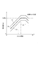
- a graph showing the relationship between the throttle opening degree and the intake air amount (opening degree-intake flow rate characteristic) according to the first embodiment.
- the flowchart which shows the content of the setting process of the target intake amount which concerns on 1st Embodiment.
- FIG. 6 is a schematic view showing a relationship between a throttle device and an ECU according to a third embodiment.
- An estimated opening degree map referred to in order to obtain an estimated opening degree according to the intake air amount and the engine speed according to the third embodiment.
- FIG. 6 is a schematic view showing a relationship between a throttle device and an ECU according to a fourth embodiment.
- FIG. 5 is a flowchart showing the contents of throttle control according to the fourth embodiment.
- FIG. 5 is a flowchart showing the content of the correction process of the estimated opening degree according to the fourth embodiment.
- FIG. 6 is a schematic view showing a relationship between a throttle device and an ECU according to a fifth embodiment.
- FIG. 5 is a flowchart showing the content of the correction process of the estimated opening degree according to the fifth embodiment.
- FIG. 5 is a flowchart showing the contents of PID control according to the sixth embodiment.
- FIG. 5 is a graph schematically showing an opening degree-intake amount characteristic in the vicinity of the throttle valve fully opened according to the seventh embodiment.
- FIG. 5 is a flowchart showing the content of the target opening degree limiting process according to the ninth embodiment.
- FIG. 5 is a flowchart showing the contents of a target opening degree setting process according to the tenth embodiment.
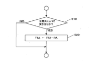
- FIG. 5 is a flowchart showing the contents of a target opening degree setting process according to the tenth embodiment.
- FIG. 1 shows a schematic configuration diagram of a gasoline engine system (hereinafter, simply referred to as “engine system”) in this embodiment.
- engine system an engine system mounted on a series hybrid vehicle (HV vehicle)
- series-type HV vehicles basically drive a driving motor with battery power to run, and when the battery power is low, the engine drives a generator to generate electricity, and that power is used. It has a mechanism for driving a traveling motor to travel.
- the engine system mounted on this HV vehicle includes an engine 1.
- the engine 1 is a four-cycle reciprocating engine, which includes a plurality of cylinders 2 including a combustion chamber, a crankshaft 3, and well-known components.
- the engine 1 is provided with an intake passage 4 for introducing intake air into each cylinder 2 and an exhaust passage 5 for deriving exhaust gas from each cylinder 2.
- An air cleaner 6 is provided at the inlet of the intake passage 4.
- a surge tank 4a is provided in the middle of the intake passage 4, and a throttle device 7 is provided on the upstream side of the surge tank 4a.
- the throttle device 7 includes a throttle valve 7a composed of a butterfly valve for adjusting the intake air sucked into the engine 1, and a DC motor 8 for driving the throttle valve 7a with a variable opening degree.
- the engine system of this embodiment is not provided with a throttle sensor for detecting the opening degree (throttle opening degree) of the throttle valve 7a.
- the throttle device 7 adjusts the intake amount Ga flowing through the intake passage 4 by opening and closing the throttle valve 7a.
- the exhaust passage 5 is provided with a catalyst 9 for purifying the exhaust gas.
- the intake passage 4 is provided with an injector 10 for injecting fuel corresponding to each cylinder 2 of the engine 1.
- Each injector 10 is configured to inject fuel (gasoline) supplied from a fuel supply device (not shown).
- a combustible air-fuel mixture is formed by the fuel injected from each injector 10 and the intake air introduced from the intake passage 4 in the intake stroke.
- the engine 1 is provided with spark plugs 11 corresponding to each of the cylinders 2.
- Each spark plug 11 receives an ignition signal output from the ignition coil 12 and performs a spark operation.
- Both parts 11 and 12 constitute an ignition device for igniting a combustible air-fuel mixture in each cylinder 2.
- the combustible air-fuel mixture explodes and burns due to the spark operation of each spark plug 11 in the compression stroke, and the explosion stroke elapses.
- the exhaust gas after combustion is discharged from each cylinder 2 to the exhaust passage 5 in the exhaust stroke, flows through the catalyst 9, is purified, and is discharged to the outside.
- the starter motor 14 for cranking (starting) the engine 1 is driven and connected to the crankshaft 3.
- Various sensors 41 to 46 provided corresponding to the engine 1 constitute means for detecting the operating state of the engine 1.
- An accelerator sensor 41 is provided on the accelerator pedal 16 provided in the driver's seat.
- the accelerator sensor 41 detects the depression angle, which is the amount of operation of the accelerator pedal 16, as the accelerator opening ACC, and outputs an electric signal according to the detected value.
- the water temperature sensor 42 provided in the engine 1 detects the temperature (cooling water temperature) THW of the cooling water flowing inside the cylinder block of the engine 1 and outputs an electric signal according to the detected value.
- the rotation speed sensor 43 provided in the engine 1 detects the rotation speed (engine rotation speed) NE of the crankshaft 3 and outputs an electric signal according to the detected value.
- the air flow meter 44 provided in the air cleaner 6 detects the amount of intake air Ga flowing through the intake passage 4, and outputs an electric signal according to the detected value.
- the intake pressure sensor 45 provided in the surge tank 4a detects the intake pressure PM in the surge tank 4a (intake passage 4) and outputs an electric signal according to the detected value.
- the air-fuel ratio sensor 46 provided in the exhaust passage 5 detects the air-fuel ratio A / F in the exhaust gas discharged to the exhaust passage 5, and outputs an electric signal according to the detected value.
- the rotation speed sensor 43, the air flow meter 44, and the intake pressure sensor 45 are at least physical quantities related to the operating state of the engine 1 and correlate with the opening degree of the throttle valve 7a.
- the air-fuel ratio sensor 46 corresponds to an example of means for detecting the air-fuel ratio of the engine 1 in the disclosed technology.
- This engine system includes an electronic control device (ECU) 50 for controlling the operation of the engine 1.
- ECU electronice control device
- Various sensors and the like 41 to 46 are connected to the ECU 50, respectively.
- the DC motor 8 of the throttle device 7, each injector 10, and the ignition coil 12 are connected to the ECU 50, respectively.
- the ECU 50 corresponds to an example of the control means in the disclosed technology for controlling the throttle device 7 based on the detected physical quantity.
- the ECU 50 corresponds to an example of means for calculating the air-fuel ratio correction amount of the engine 1 in the disclosed technology.
- the ECU 50 includes a central processing unit (CPU), various memories, an external input circuit, an external output circuit, and the like.
- the ECU 50 controls the throttle device 7 (DC motor 8), each injector 10, and the ignition coil 12 based on electric signals from various sensors 41 to 46 in order to operate the engine 1. It has become. Further, the ECU 50 executes a predetermined throttle control in order to control the throttle device 7 without using the throttle sensor.
- the generator 31 is driven by the engine 1 to generate electric power, the electric power is charged to the battery 33 via the inverter 32, and the electric power is charged to the traveling motor 34.
- the drive wheels (not shown) are driven to drive the vehicle.
- FIG. 2 is a schematic view of the structure of the bore 18 of the throttle device 7.
- FIG. 3 graphically shows the relationship (opening-intake flow rate characteristic) between the throttle opening degree and the intake air amount Ga for the throttle device 7.
- the throttle device 7 includes a bore 18 that is opened and closed by a throttle valve 7a and in which intake air flows.
- the throttle valve 7a composed of the butterfly valve is arranged in the bore 18.
- the bore 18 includes an intermediate portion 18a formed with the same inner diameter in the axial direction thereof, and an upstream side portion 18b and a downstream side portion 18c formed at both ends of the intermediate portion 18a.
- the intake air that has flowed into the upstream side portion 18b is regulated by the throttle valve 7a at the intermediate portion 18a and flows out from the downstream side portion 18c.
- the upstream side portion 18b has a tapered shape in which the inner diameter gradually increases from the intermediate portion 18a toward the upstream side of the intake air flow.
- the downstream side portion 18c has a tapered shape in which the inner diameter gradually increases from the intermediate portion 18a toward the downstream side of the intake air flow.
- the shapes of the upstream side portion and the downstream side portion of the conventional bore extend in the axial direction with the same inner diameter as the intermediate portion 18a, as shown by the two-dot chain line in FIG. Therefore, as shown in FIG.
- the opening degree TA1 in the vicinity of full opening where the intake amount Ga reaches the maximum value Ga1 is also shown by the broken line in FIG. It can be set to be smaller than the opening degree TA2 near the full opening of the conventional bore that reaches the maximum value Ga1.
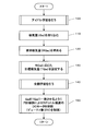
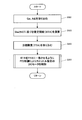
- FIG. 4 shows the contents of the throttle control of this embodiment by a flowchart.
- the physical quantity related to the "required physical quantity" in the disclosed technique is an intake amount Ga.
- step 100 the ECU 50 performs idle learning of the throttle valve 7a.
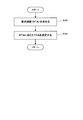
- FIG. 5 shows the contents of this idle learning by a flowchart.
- step 101 of FIG. 5 the ECU 50 determines whether or not there is an idle learning request.
- the ECU 50 shifts the process to step 102 when there is an idle learning request, and shifts the process to step 110 of FIG. 4 when there is no idle learning request.
- step 102 the ECU 50 operates the engine 1 by motoring (controlling the starter motor 14), and controls the DC motor 8 of the throttle device 7 by PID control until the intake amount Ga reaches a predetermined value Ga2.
- step 103 the ECU 50 determines whether or not the intake amount Ga is equal to the predetermined value Ga2. If the determination result is affirmative, the ECU 50 shifts the process to step 104, and if the determination result is negative, the ECU 50 shifts the process to step 110 of FIG.
- step 104 the ECU 50 operates the engine 1 by firing (burning fuel in the engine 1), and then shifts the process to step 110 in FIG.
- the engine 1 when the ECU 50 determines that there is an idle learning request for the engine 1, the engine 1 is operated by the motoring that controls the starter motor 14, and the detected intake amount Ga (physical quantity) is a predetermined value.
- the throttle device 7 is controlled by PID control so as to be Ga2, and after the detected intake amount Ga (physical quantity) reaches a predetermined value Ga2, the engine 1 is operated by firing to burn fuel in the engine 1. It has become.
- step 110 of FIG. 4 the ECU 50 takes in the intake amount Ga detected by the air flow meter 44.
- the ECU 50 obtains the required intake amount RGa as the required physical quantity in this disclosed technology.
- the ECU 50 obtains the required intake amount RGa required by the HV vehicle or the engine 1 based on at least one parameter of, for example, the accelerator opening ACC, the engine speed NE, the intake pressure PM, and the charge amount of the battery 33. Can be done.
- step 130 the ECU 50 sets the target intake amount TGa as the target physical quantity in this disclosed technology according to the required intake amount RGa.
- FIG. 6 shows the contents of the setting process of the target intake amount TGa by a flowchart.
- step 131 of FIG. 6 the ECU 50 determines whether or not the required intake amount RGa is equal to or greater than the maximum value Ga1 corresponding to the vicinity of the throttle valve 7a fully opened. If the determination result is affirmative, the ECU 50 shifts the process to step 132, and if the determination result is negative, the ECU 50 shifts the process to step 134.
- step 132 the ECU 50 determines whether or not a predetermined time or more has passed since the first step or the previous step update.
- the opening degree is step-updated (updated stepwise), so that this determination is made. If the determination result in step 132 is affirmative, the ECU 50 shifts the process to step 133, and if the determination result is negative, the ECU 50 shifts the process to step 134.
- step 133 the ECU 50 updates the step. That is, the ECU 50 obtains a new target intake amount TGa by adding a predetermined value ⁇ a to the previous target intake amount TGaO.
- the target intake amount TGa is limited to the required intake amount RGa or less.
- the ECU 50 sets the target intake amount TGa for the intake amount Ga corresponding to the vicinity of the throttle valve 7a fully opened by a predetermined value ⁇ a at predetermined time intervals. It is gradually changed to RGa.
- step 134 the ECU 50 determines whether or not the target intake amount TGa is being driven by the step update mode, that is, whether or not the step update in step 133 is being performed. If the determination result is affirmative, the ECU 50 shifts the process to step 135, and if the determination result is negative, the ECU 50 shifts the process to step 140 of FIG.
- step 135 the ECU 50 determines whether or not there is a change in the intake air amount Ga after a predetermined time has elapsed from the step update. If the determination result is affirmative, the ECU 50 shifts the process to step 136, and if the determination result is negative, the ECU 50 shifts the process to step 140 of FIG.
- step 136 the ECU 50 finishes the step update. That is, the ECU 50 obtains a new target intake amount TGa by subtracting a predetermined value ⁇ a from the previous target intake amount TGaO.
- the target intake amount TGa target physical quantity
- the target intake amount TGa target physical quantity
- the ECU 50 steps the opening degree of the throttle valve 7a while checking the change in the intake amount Ga.
- the throttle device 7 is controlled to increase the number.
- the ECU 50 controls the throttle device 7 so as to return the opening degree of the throttle valve 7a to the state one step before.
- the opening degree of the throttle valve 7a enters the uncontrollable region, the opening and lowering of the throttle valve 7a is repeated by one step.
- the throttle device 7 can be controlled with the uncontrollable range as the upper limit.
- step 140 of FIG. 4 the ECU 50 performs full-open learning.
- FIG. 7 shows the contents of this fully open learning by a flowchart.
- step 141 the ECU 50 determines whether or not a certain time or one trip or more has elapsed since the previous fully open learning. If the determination result is affirmative, the ECU 50 shifts the process to step 142, and if the determination result is negative, the ECU 50 shifts the process to step 150 of FIG.
- step 142 the ECU 50 determines whether or not the engine 1 is inactive (no charge request). The ECU 50 can make this determination based on, for example, the engine speed NE or the charge amount of the battery 33. If the determination result is affirmative, the ECU 50 shifts the process to step 143, and if the determination result is negative, the ECU 50 shifts the process to step 150 of FIG.
- step 143 the ECU 50 operates the engine 1 by motoring, limits the duty value DV of the feedback (F / B) control amount CNfb, operates the throttle valve 7a to the full open, and performs full open learning. Specifically, the intake amount Ga corresponding to the fully open is learned as the target intake amount TGa.
- step 144 the ECU 50 determines whether or not the predetermined time has elapsed. If the determination result is affirmative, the ECU 50 shifts the process to step 145, and if the determination result is negative, the ECU 50 shifts the process to step 150 of FIG.
- step 145 the ECU 50 determines whether or not the intake pressure PM detected by the intake pressure sensor 45 is equal to or less than the standard atmospheric pressure PAst stored in advance. If the determination result is affirmative, the ECU 50 shifts the process to step 146, and if the determination result is negative, the ECU 50 shifts the process to step 150 of FIG.
- step 146 the ECU 50 sets a limit on the duty value DV of the F / B control amount CNfb after the engine is operated.
- setting a limit on the duty value DV of the F / B control amount CNfb means that if the calculation result exceeds the duty value DV, the calculation result is replaced with the duty value DV.
- the duty value DV of the control amount CNfb is limited. That is, the ECU 50 limits the control of the throttle device 7 when the atmospheric pressure is lower than the standard atmospheric pressure.
- step 150 of FIG. 4 the ECU 50 controls the DC motor 8 of the throttle device 7 by PID control so that the intake amount Ga matches the target intake amount TGa. Further, when the ECU 50 detects that the atmospheric pressure is low in the fully open learning in step 140, the ECU 50 limits the duty value DV.
- FIG. 8 shows the contents of this PID control by a flowchart.
- step 151 the ECU 50 calculates the intake amount difference DGa by subtracting the detected intake amount Ga from the target intake amount TGa.
- step 152 the ECU 50 calculates the proportional term Vp by multiplying the predetermined proportional gain Kp by the intake amount difference DGa.
- step 153 the ECU 50 calculates the differential term Vd by multiplying the negative differential gain ⁇ Kd by the differential value d (Ga) / dt of the intake air amount.
- step 154 the ECU 50 calculates the integral term Vi by integrating the result of multiplying the sum of the proportional term Vp and the differential term Vd by the integral gain Ki.
- step 155 the ECU 50 calculates the F / B control amount CNfb by adding the proportional term Vp, the differential term Vd, and the integral term Vi.
- the ECU 50 controls the DC motor 8 of the throttle device 7 by the F / B control amount CNfb.
- the F / B control amount CNfb is configured by the duty value DV, and the ECU 50 applies the above-set limit to the duty value DV.
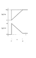
- FIG. 9 shows an operation image of the throttle valve 7a by the DC motor 8 described above when the differential term Vd is not used in FIG. 8 by a time chart.
- (a) shows a change in the intake amount Ga
- (b) shows a change in the duty value DV (F / B control amount CNfb).
- the solid line shows the change in the actual intake amount Ga
- the broken line shows the change in the target intake amount TGa.
- the duty value DV starts from "0%" as shown in (b).
- the ECU 50 controls the DC motor 8 by changing the duty value DV in order to adjust the intake amount Ga to the target intake amount TGa.
- the time T1 from the time t1 to the time t2, that is, the adjustment time of the intake amount Ga is increased as compared with the case where the differential term Vd is used.
- responsiveness is not required for the operation of the engine 1 in the series type HV vehicle, it is considered that there is a sufficient possibility that PI control that does not use the differential term Vd can be applied to throttle control to simplify the control. Be done.
- the ECU 50 sets a target intake amount TGa (target physical quantity) based on at least the required intake amount RGa (required physical quantity) according to the operating state of the engine 1, and the detected intake amount Ga.
- the throttle device 7 is controlled by PID control so that the (physical quantity) matches the target intake amount TGa (target physical quantity).
- the air flow meter 44 is at least a physical quantity related to the operating state of the engine 1 and correlates with the opening degree of the throttle valve 7a of the throttle device 7 and has an opening degree thereof.
- the intake amount Ga as a physical quantity other than is detected.
- the ECU 50 sets a target intake amount TGa (target physical quantity) based on at least the required intake amount RGa (required physical quantity) according to the operating state of the engine 1, and sets the detected intake amount Ga (physical quantity) as the target intake amount TGa.
- the throttle device 7 is controlled by PID control so as to match (target physical quantity).
- the PID control is performed so that the detected intake amount Ga (physical quantity) matches the target intake amount TGa (target physical quantity) reflecting the operating state of the engine 1, so that the throttle device 7 Can be controlled according to the operating state of the engine 1.
- the air flow meter 44 used for the operation control of the engine 1 detects the intake amount Ga as a physical quantity, so that the throttle device 7 can be controlled by the ECU 50. Therefore, the throttle device 7 can be appropriately controlled at least according to the operating state of the engine 1 without providing the throttle sensor. As a result, it is possible to reduce the cost of the throttle control device, reduce the harness (wiring), and reduce the size (improvement of vehicle mountability).
- the ECU 50 when the throttle valve 7a is at the opening degree before the throttle valve 7a is fully opened, the ECU 50 stepwise increases the target intake amount TGa (target physical quantity) while checking the change in the intake amount Ga (physical quantity). Therefore, the opening degree of the throttle valve 7a is gradually increased toward full opening. After that, when the change in the intake amount Ga (physical quantity) decreases or disappears, the ECU 50 returns the target intake amount TGa (target physical quantity) to the state one step before, so that the intake amount Ga (physical quantity) can change at the maximum.
- the state of the throttle opening is the target intake amount TGa (target value). Therefore, the abutting (fully open abutting) of the throttle valve 7a against the fully open stopper (not shown) can be relaxed, and damage to the DC motor 8 (throttle device 7) can be avoided.
- the ECU 50 when there is an idle learning request for the engine 1, the ECU 50 operates the engine 1 by motoring, and the throttle device 7 is controlled by PID so that the intake amount Ga (physical quantity) becomes a predetermined value Ga2. After the intake amount Ga (physical quantity) reaches a predetermined value Ga2, the engine 1 is operated by firing. Therefore, the operating time of the engine 1 for idle learning is shortened. Therefore, the quietness of the engine 1 at the time of idling can be improved.
- the ECU 50 limits the control of the throttle device 7 when it determines that the atmospheric pressure is lower than the standard atmospheric pressure, so that the throttle valve 7a is prevented from hitting the throttle valve 7a at full throttle.
- damage to the throttle device 7 can be avoided even at low atmospheric pressure such as when the altitude is high.
- the bore 18 of the throttle device 7 since the bore 18 of the throttle device 7 has a tapered shape (upstream side portion 18b) whose inner diameter gradually expands toward the upstream side of the intake air flow, a cylindrical bore having a uniform inner diameter.
- the throttle valve 7a when the throttle valve 7a has a low opening degree, the intake amount Ga increases and the maximum flow rate is reached. In this sense as well, the fully open abutment of the throttle valve 7a can be relaxed, and damage to the DC motor 8 (throttle device 7) can be avoided.
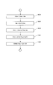
- FIG. 10 shows the contents of the throttle control by a flowchart. This embodiment is different from the throttle control shown in FIG. 4 of the first embodiment in that steps 100 and 140 are omitted as shown in FIG.
- the ECU 50 first takes in the intake amount Ga detected by the air flow meter 44 in step 110.
- step 120 the ECU 50 obtains the required intake amount RGa.
- the method of this calculation is the same as that of the first embodiment.
- step 130 the ECU 50 sets the target intake amount TGa according to the required intake amount RGa.
- the method of this setting is the same as that of the first embodiment.
- step 150 the ECU 50 controls the DC motor 8 of the throttle device 7 by PID control so that the detected intake amount Ga matches the target intake amount TGa.
- This control method is the same as that of the first embodiment.
- the throttle device 7 can be controlled by the ECU 50. Therefore, the throttle device 7 can be appropriately controlled at least according to the operating state of the engine 1 without providing the throttle sensor. As a result, it is possible to reduce the cost of the throttle control device, reduce the harness (wiring), and reduce the size (improvement of vehicle mountability).
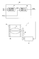
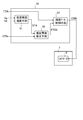
- FIG. 11 is a schematic view showing the relationship between the throttle device 7 and the ECU 50 constituting the control means.
- the throttle device 7 of this embodiment includes a casing 19, and the bore 20 formed in the casing 19 is formed with the same inner diameter in the axial direction thereof.
- a throttle valve 7a composed of a butterfly valve is rotatably provided on the bore 20. The throttle valve 7a is driven and connected to the DC motor 8 via the reduction gear 21.
- the ECU 50 includes an estimated opening degree calculating means 51 and an opening degree feedback (F / B) controlling means 52, each of which is composed of an electric circuit.
- the intake air amount Ga detected by the air flow meter 44 and the engine speed NE detected by the rotation speed sensor 43 are input to the estimated opening degree calculation means 51.
- the estimated opening degree calculating means 51 calculates the estimated opening degree STA of the throttle valve 7a based on the input intake air amount Ga and the engine speed NE.
- the estimated opening STA is input from the estimated opening calculation means 51, and the target opening TTA is input to the opening F / B control means 52.
- the ECU 50 separately calculates the target opening degree TTA.
- the opening degree F / B control means 52 calculates the F / B control amount CNfb based on the input estimated opening degree STA and the target opening degree TTA, and controls the DC motor 8 based on the F / B control amount CNfb. It has become.
- FIG. 12 shows the contents of the throttle control of this embodiment by a flowchart.
- the intake amount Ga and the engine speed NE are used as the physical quantities related to the required physical quantity and the target physical quantity of the disclosed technology.
- step 300 the ECU 50 takes in the intake air amount Ga detected by the air flow meter 44 and the engine speed NE detected by the rotation speed sensor 43.
- step 310 the ECU 50 calculates the estimated opening degree STA of the throttle valve 7a based on the intake intake amount Ga and the engine speed NE.
- the ECU 50 can obtain an estimated opening degree STA according to the intake amount Ga and the engine speed NE, for example, by referring to the estimated opening degree map as shown in FIG. According to this map, the estimated opening STA becomes smaller as the engine speed NE increases at a specific intake amount Ga, and increases as the intake amount Ga increases at a specific engine speed NE.
- the process of step 310 is performed by the estimated opening degree calculation means 51 of the ECU 50.
- step 320 the ECU 50 takes in the target opening TTA of the throttle valve 7a.
- the ECU 50 can set this target opening degree TTA based on at least a required physical quantity according to the operating state of the engine 1. The process of setting the target opening TTA will be described later.
- step 330 the ECU 50 controls the DC motor 8 of the throttle device 7 by PID control so that the estimated opening STA matches the target opening TTA.
- the process of step 330 is performed by the opening degree F / B control means 52 of the ECU 50.
- FIG. 14 shows the contents of this PID control by a flowchart.
- step 331 the ECU 50 calculates the opening difference DTA by subtracting the estimated opening STA from the target opening TTA.
- step 332 the ECU 50 calculates the proportional term Vp by multiplying the predetermined proportional gain Kp by the opening difference DTA.
- step 333 the ECU 50 calculates the differential term Vd by multiplying the negative differential gain ⁇ Kd by the differential value d (STA) / dt of the estimated opening STA.
- step 334 the ECU 50 calculates the integral term Vi by integrating the result of multiplying the sum of the proportional term Vp and the differential term Vd by the integral gain Ki.
- step 335 the ECU 50 calculates the F / B control amount CNfb by adding the proportional term Vp, the differential term Vd, and the integral term Vi.
- the ECU 50 controls the DC motor 8 of the throttle device 7 by the F / B control amount CNfb.
- the F / B control amount CNfb is composed of the duty value DV.
- FIG. 15 shows the contents of the setting process of the target opening TTA by a flowchart.
- the ECU 50 obtains the required opening degree RTA as the required physical quantity.
- the ECU 50 may obtain the required opening degree RTA required by the vehicle or the engine 1 based on at least one parameter of, for example, the accelerator opening degree ACC, the engine speed NE, the intake pressure PM, and the charge amount of the battery 33. it can.
- the ECU 50 sets the target opening TTA as the target physical quantity according to the required opening RTA.
- the ECU 50 can set the target opening degree TTA according to the required opening degree RTA, for example, by referring to a predetermined map.
- the ECU 50 takes in the target opening TTA set as described above in step 320 of FIG.
- the ECU 50 sets the target opening TTA as the target physical quantity from the required opening RTA as the required physical quantity, and estimates the opening degree based on the detected intake amount Ga and the engine speed NE.
- the throttle device 7 is controlled by PID control so as to calculate the STA and match the estimated opening STA with the target opening TTA.
- the air flow meter 44 and the rotation speed sensor 43 are related to at least the operating state of the engine 1, and the intake amount Ga and the engine rotation are correlated with the opening degree of the throttle valve 7a. Detect a few NEs. Further, the ECU 50 sets the target opening TTA (target physical quantity) based on at least the required opening RTA (required physical quantity) according to the operating state of the engine 1, and is based on the detected intake amount Ga and the engine speed NE. The estimated opening STA is calculated. Then, the ECU 50 controls the throttle device 7 by PID control so that the estimated opening degree STA matches the target opening degree TTA.
- target opening TTA target physical quantity
- RTA reactive physical quantity
- the estimated opening degree STA is calculated from the intake amount Ga and the engine speed NE, it is possible to execute the throttle control with relatively high accuracy. Further, in the throttle device 7, the opening degree-intake amount characteristic of the throttle device 7 may change due to the adhesion of a deposit to the bore 20 or the like on the low opening degree side of the throttle valve 7a. However, in this embodiment, since the estimated opening STA is calculated based on the intake amount Ga and the engine speed NE, the estimated opening STA is not affected by the above-mentioned change in the opening-intake amount characteristic.
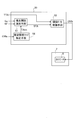
- FIG. 16 is a schematic view showing the relationship between the throttle device 7 and the ECU 50 constituting the control means.
- the ECU 50 includes an estimated opening degree calculating means 51, an opening degree F / B control means 52, and an estimated opening degree correcting means 53, each of which is composed of an electric circuit.
- the estimated opening degree STA calculated by the estimated opening degree calculating means 51 is corrected by the estimated opening degree correcting means 53.
- the modified estimated opening degree FSTA is input to the opening degree F / B control means 52.
- the estimated opening degree STA and the air-fuel ratio correction amount CRfa are input to the estimated opening degree correction means 53.
- the air-fuel ratio correction amount CRfa is calculated separately by the ECU 50 based on the air-fuel ratio A / F detected by the air-fuel ratio sensor 46.
- the estimated opening degree correcting means 53 corrects the input estimated opening degree STA based on the air-fuel ratio correction amount CRfa to obtain the corrected estimated opening degree FSTA. Then, the target opening degree TTA and the modified estimated opening degree FSTA are input to the opening degree F / B control means 52.
- the opening degree F / B control means 52 calculates the F / B control amount CNfb based on the input modified estimated opening degree FSTA and the target opening degree TTA, and the DC motor of the throttle device 7 based on the F / B control amount CNfb. 8 is controlled.
- the intake amount Ga detected by the air flow meter 44 varies due to the difference in altitude or the product variation of the air flow meter 44. This also applies to the intake pressure PM detected by the intake pressure sensor 45. In this embodiment, the following throttle control is executed in order to cope with the detected deviation of the intake air amount Ga.
- FIG. 17 shows the contents of the throttle control of this embodiment by a flowchart. This embodiment differs from the contents of the flowchart of FIG. 12 in that the contents of steps 400 and 337 are different.
- step 300 the ECU 50 takes in the intake air amount Ga detected by the air flow meter 44 and the engine speed NE detected by the rotation speed sensor 43.
- step 310 the ECU 50 calculates the estimated opening degree STA of the throttle valve 7a based on the intake intake amount Ga and the engine speed NE.
- step 400 the ECU 50 modifies the estimated opening degree STA to obtain the modified estimated opening degree FSTA.
- the process of this step 400 is performed by the estimated opening degree correction means 53 of the ECU 50.
- FIG. 18 shows the content of this correction process by a flowchart.
- step 401 the ECU 50 takes in the air-fuel ratio correction amount CRfa.
- step 402 the ECU 50 determines whether or not the absolute value of the air-fuel ratio correction amount CRfa is equal to or greater than the predetermined value K1. If the determination result is affirmative, the ECU 50 shifts the process to step 403, and if the determination result is negative, the ECU 50 shifts the process to step 320 of FIG.
- step 403 the ECU 50 sets the function f (CRfa) of the air-fuel ratio correction amount CRfa as the correction amount FA.
- step 404 the ECU 50 calculates the modified estimated opening FSTA by adding the modified amount FA to the estimated opening STA, and shifts the process to step 320 in FIG.
- step 320 of FIG. 17 the ECU 50 takes in the target opening TTA of the throttle valve 7a.
- the intake air amount Ga is deviated, so that the correction amount according to the air-fuel ratio correction amount CRfa Calculate FA.
- the correction estimated opening degree FSTA is calculated by adding the correction amount FA to the estimated opening degree STA.
- step 337 the ECU 50 controls the DC motor 8 of the throttle device 7 by PID control so that the modified estimated opening degree FSTA matches the target opening degree TTA.
- the process of step 335 is performed by the opening degree F / B control means 52 of the ECU 50.
- the content of the PID control in step 335 conforms to the flowchart of FIG.
- the ECU 50 corrects the estimated opening degree STA based on the calculated air-fuel ratio correction amount CRfa, and PID controls the corrected estimated opening degree FSTA so as to match the target opening degree TTA.
- the throttle device 7 is controlled by the above.
- FIG. 19 is a schematic view showing the relationship between the throttle device 7 and the ECU 50 constituting the control means.
- the ECU 50 includes an estimated opening degree calculating means 51, an opening degree F / B control means 52, and an estimated opening degree map correcting means 54, each of which is composed of an electric circuit.
- the ECU 50 of this embodiment corrects the estimated opening degree map referred to by the estimated opening degree calculating means 51 for calculating the estimated opening degree STA by the estimated opening degree map correcting means 54. It has become.
- the air-fuel ratio correction amount CRfa is input to the estimated opening degree map correction means 54.
- the estimated opening degree map correcting means 54 corrects the map value Tann of the estimated opening degree map based on the input air-fuel ratio correction amount CRfa.
- the estimated opening degree calculation means 51 calculates the estimated opening degree STA by referring to the modified estimated opening degree map.
- the opening degree F / B control means 52 calculates the F / B control amount CNfb based on the input estimated opening degree STA and the target opening degree TTA, and the DC motor 8 of the throttle device 7 is based on the F / B control amount CNfb. To control.
- the following throttle control is executed in order to cope with the detected deviation of the intake air amount Ga.
- FIG. 20 shows the contents of the throttle control of this embodiment by a flowchart. This embodiment differs from the contents of the flowchart shown in FIG. 12 in that the process of step 500 is provided between step 300 and step 310.
- step 500 the ECU 50 corrects the estimated opening degree map.
- the process of this step 500 is performed by the estimated opening degree map correction means 54 of the ECU 50.
- FIG. 21 shows the content of this correction process by a flowchart.
- the contents of the processes of steps 501 to 503 are the same as those of steps 401 to 403 of the flowchart of FIG.
- step 504 after shifting from step 503, the ECU 50 corrects the map value Tann by adding the correction amount FA to the corresponding map value Tann in the estimated opening degree map. That is, as shown in FIG. 22, in the estimated opening degree map in which the map value is set from the relationship between the intake air amount Ga and the engine speed NE, the ECU 50 corrects the corresponding map value Tann by the modified map value Tann. ..
- the ECU 50 includes a predetermined estimated opening degree map in which the estimated opening degree STA corresponding to the intake amount Ga and the engine speed NE is set, and is estimated based on the calculated air-fuel ratio correction amount CRfa.
- the estimated opening degree STA is calculated based on the detected intake amount Ga and the engine speed NE. Then, the ECU 50 controls the throttle device 7 by PID control so that the calculated estimated opening degree STA matches the target opening degree TTA.
- the configuration of this embodiment is different from that of the third embodiment mainly in terms of the content of throttle control.
- FIG. 23 shows the contents of the throttle control of this embodiment by a flowchart.
- the flowchart of FIG. 23 is different in that the process of step 350 is provided instead of the process of step 330 in the flowchart of FIG.
- FIG. 24 shows the contents of the PID control in step 350 by a flowchart.
- step 351 the ECU 50 takes in the engine speed NE based on the detection value of the speed sensor 43.
- step 352 the ECU 50 sets various gains Kp, Kd, Ki, and Ka according to the engine speed NE. That is, the magnitudes of various gains Kp, Kd, Ki, and Ka are set according to the engine speed NE.
- step 353 the ECU 50 calculates the opening difference DTA by subtracting the estimated opening STA from the target opening TTA.
- step 354 the ECU 50 calculates the proportional term Vp by multiplying the proportional gain Kp and the opening difference DTA.
- step 355 the ECU 50 calculates the differential term Vd by multiplying the negative differential gain ⁇ Kd by the differential value d (STA) / dt of the estimated opening STA.
- step 356 the ECU 50 calculates the integral term Vi by integrating the result of multiplying the sum of the proportional term Vp and the differential term Vd by the integral gain Ki.
- step 357 the ECU 50 calculates the acceleration term Va by multiplying the negative double differential gain ⁇ Ka by the acceleration value d 2 (STA) / dt 2 of the estimated opening degree STA.
- step 358 the ECU 50 calculates the F / B control amount CNfb by adding the proportional term Vp, the differential term Vd, the integral term Vi, and the acceleration term Va.
- the ECU 50 controls the DC motor 8 of the throttle device 7 by the F / B control amount CNfb.
- the ECU 50 is proportional to the proportional term Vp according to the opening difference DTA (deviation) of the estimated opening STA with respect to the target opening TTA and the differential term Vd of the estimated opening STA.
- the integral term Vi of the sum of the term Vp and the differential term Vd and the acceleration term Va of the estimated opening degree STA are calculated.
- the ECU 50 calculates the F / B control amount CNfb from the sum of the proportional term Vp, the differential term Vd, the integral term Vi, and the acceleration term Va, and controls the throttle device 7 based on the calculated F / B control amount CNfb. It is designed to do.
- the ECU 50 has a proportional gain Kp for calculating the proportional term Vp, a differential gain Kd for calculating the differential term Vd, an integral gain Ki for calculating the integral term Vi, and an acceleration term. It is provided with an acceleration gain Ka for calculating Va, and a proportional gain Kp, a differential gain Kd, an integral gain Ki, and an acceleration gain Ka are set according to the engine rotation speed NE.
- FIG. 25 shows the behavior of various parameters by the PID control by a time chart.
- (a) is the target opening TTA and the estimated opening STA
- (b) is the opening difference DTA
- (c) is the differential value d (STA) / dt
- (d) is the acceleration value d. 2 (STA) / dt 2 and (e) indicate the F / B control amount CNfb.
- the target opening degree TTA is set to a certain value at time t1
- the opening degree difference DTA rises to a certain value
- (e) the F / B control amount CNfb rises to a certain value. ..
- the ECU 50 has a proportional gain Kp for calculating the proportional term Vp, a differential gain Kd for calculating the differential term Vd, an integral gain Ki for calculating the integral term Vi, and
- the acceleration gain Ka for calculating the acceleration term Va is set according to the engine rotation speed NE, respectively. Therefore, the time response delay of the intake amount Ga with respect to the change in the opening degree of the throttle valve 7a, which differs depending on the engine speed NE, is reduced. In this sense, with respect to the control of the throttle device 7, overshoot due to response delay can be further suppressed, and the control can be further stabilized.
- the throttle opening is estimated from the intake amount Ga and the engine speed NE (estimated opening STA), and the throttle is throttled so that the estimated opening STA becomes the target opening TTA.
- the controllability in the vicinity of the fully open throttle device 7 may become a problem due to variations or deviations in the intake air amount Ga in the intake passage 4. That is, there may be problems such as deterioration of controllability of the intake amount Ga due to variation or variation in the opening degree-intake amount characteristic, abutting against the fully open stopper of the throttle valve 7a, and the like.
- FIG. 26 schematically shows a characteristic (opening-intake amount characteristic) of the relationship between the throttle opening degree and the intake amount Ga in the vicinity of the throttle valve 7a being fully opened.
- the horizontal axis represents the throttle opening degree
- the vertical axis represents the intake amount Ga.
- the solid line C0 shows a representative characteristic (map characteristic)
- the upper broken line C1 shows the first characteristic
- the lower broken line C2 shows the second characteristic.
- the opening-intake amount characteristics will vary.
- the intake amount Ga decreases due to the decrease in atmospheric pressure, so that the opening degree-intake amount characteristic becomes like the second characteristic of the broken line C2.
- the intake amount-estimated opening degree is based on the characteristics that take into account the decrease in the intake amount Ga in the highlands in advance in addition to the lower limit of the variation. It is designed to set the map.
- the ECU 50 sets an opening map in the estimated opening STA according to the product variation of the throttle device 7 or the difference in the intake amount Ga due to the altitude, and the estimated opening STA matches the target opening TTA.
- the throttle device 7 is controlled by PID control so as to cause the throttle device 7.
- This embodiment is premised on the same problems as the seventh embodiment, but the configuration is different from that of the seventh embodiment in terms of the content of throttle control.
- This embodiment differs from the third embodiment in that, for example, a restriction process relating to the target opening degree TTA as described below is added between steps 320 and 330 in FIG. 12 of the third embodiment. ..
- FIG. 27 shows the content of the restriction processing by a flowchart.
- the ECU 50 determines whether or not the throttle valve 7a hits the fully open stopper. The ECU 50 determines, for example, when the estimated opening STA does not match the target opening TTA and the F / B control amount CNfb indicated by the duty value DV continues to be equal to or higher than a predetermined value for a predetermined time or longer. It can be determined that the end of 7a is at the fully open stopper. If the determination result is affirmative, the ECU 50 shifts the process to step 520, and if the determination result is negative, the ECU 50 shifts the process to step 330 in FIG.
- step 520 the ECU 50 changes the target opening TTA to the closed side by the return amount RA by subtracting a predetermined return amount RA from the target opening TTA taken in in step 320.
- the ECU 50 repeats this change until the abutting of the throttle valve 7a against the fully open stopper is eliminated.
- the return amount RA can be set to, for example, the angle difference between the fully open stopper position and the fully open position, or the equivalent amount can be set to the amount to be returned in small steps. After that, the ECU 50 shifts the process to step 330 in FIG.
- the throttle device 7 when the ECU 50 determines that the throttle valve 7a is at the fully open abutment (at the abutment at the fully open stopper) based on the control state of the throttle device 7, the throttle device 7 for fully opening the throttle valve 7a. It is designed to limit the control of. That is, the ECU 50 rewrites the target opening degree TTA in order to limit the operating range of the throttle device 7 to a controllable region.
- This embodiment also presupposes the same problems as the seventh embodiment, but the configuration is different from that of the seventh and eighth embodiments in terms of the content of throttle control.
- This embodiment is different from the third embodiment in that, for example, after step 330 in FIG. 12 of the third embodiment, a restriction process regarding the F / B control amount CNfb as described below is added.
- FIG. 28 shows the content of the restriction processing by a flowchart.
- step 550 after shifting from step 330 in FIG. 12, the ECU 50 determines whether or not the estimated opening degree STA is equal to or greater than the predetermined value K2.
- the predetermined value K2 corresponds to a value near the fully open throttle valve 7a. If the determination result is affirmative, the ECU 50 shifts the process to step 560, and if the determination result is negative, the ECU 50 returns the process to step 300 in FIG.
- step 560 the ECU 50 limits the F / B control amount CNfb obtained in step 330 to a predetermined value or less. That is, the ECU 50 limits the F / B control amount CNfb (output value indicated by the duty value DV) given to the DC motor 8 to a predetermined value that does not fully open when the throttle valve 7a is in the vicinity of full opening.
- the ECU 50 limits the control of the throttle device 7 when it determines that the throttle valve 7a is in the vicinity of full opening based on the control state of the throttle device 7. Specifically, the ECU 50 reduces the abutting of the throttle valve 7a against the fully open stopper by suppressing the operating speed of the DC motor 8 and suppresses the energizing current to the DC motor 8 to the throttle device 7. Damage (damage to the fully open stopper, damage to the DC motor 8) is avoided.
- This embodiment also presupposes the same problems as the seventh embodiment, but the configuration is different from that of the seventh to ninth embodiments in terms of the content of throttle control.
- This embodiment differs from the third embodiment in that, for example, a process relating to the setting of the target opening degree TTA taken in in step 320 in FIG. 12 of the third embodiment is added.
- FIG. 29 shows the content of the setting process of the target opening TTA by a flowchart.
- the ECU 50 obtains the required opening degree RTA.
- the ECU 50 may obtain the required opening degree RTA required by the vehicle or the engine 1 based on at least one parameter of, for example, the accelerator opening degree ACC, the engine speed NE, the intake pressure PM, and the charge amount of the battery 33. it can.
- step 650 the ECU 50 sets the target opening TTA according to the required opening RTA.
- FIG. 30 shows the contents of the setting process of the target opening degree TTA by a flowchart.
- step 651 of FIG. 30 the ECU 50 determines whether or not the required opening degree RTA as the required physical quantity is a predetermined value K2 or more corresponding to a value near the fully open throttle valve 7a. If the determination result is affirmative, the ECU 50 shifts the process to step 652, and if the determination result is negative, the ECU 50 shifts the process to step 654.
- step 652 the ECU 50 determines whether or not a predetermined time or more has elapsed since the first step update or the previous step update.
- the opening degree is step-updated (updated stepwise), so that this determination is made. If the determination result of step 652 is affirmative, the ECU 50 shifts the process to step 653, and if the determination result is negative, the ECU 50 shifts the process to step 654.
- step 653 the ECU 50 performs step update. That is, the ECU 50 obtains a new target opening TTA by adding a predetermined value ⁇ TA to the previous target opening TTAO.
- the target opening degree TTA is a value equal to or less than the required opening degree RTA.
- the ECU 50 sets the target opening TTA to the required opening RTA by a predetermined value ⁇ TA at predetermined time intervals with respect to the target opening TTA corresponding to the vicinity of the throttle valve 7a fully opened. Change it step by step.
- step 654 the ECU 50 determines whether or not the target opening degree TTA is being driven in the step update mode, that is, whether or not the step update in step 653 is being performed. If the determination result is affirmative, the ECU 50 shifts the process to step 655, and if the determination result is negative, the ECU 50 returns the process to step 600.
- step 655 the ECU 50 determines whether or not there is a change in the intake air amount Ga after a predetermined time has elapsed from the step update. If the determination result is affirmative, the ECU 50 shifts the process to step 656, and if the determination result is negative, the ECU 50 returns the process to step 600.
- step 656 the ECU 50 finishes the step update. That is, the ECU 50 obtains a new target opening TTA by subtracting a predetermined value ⁇ TA from the previous target opening TTAO.
- the ECU 50 increases the target opening degree TTA stepwise when it is determined that the required opening degree RTA corresponds to a state in which the throttle valve 7a is near the fully open state or more. After that, when it is determined that there is no change in the detected intake amount Ga, the target opening degree TTA is returned to the state one step before.
- the ECU 50 steps the opening degree of the throttle valve 7a while checking the change in the intake air amount Ga.
- the throttle device 7 is controlled to increase the number.
- the ECU 50 controls the throttle device 7 so as to return the opening degree of the throttle valve 7a to the state one step before.
- the opening degree of the throttle valve 7a enters the uncontrollable region, the opening and lowering of the throttle valve 7a is repeated by one step.
- the throttle device 7 can be controlled with the uncontrollable range as the upper limit.
- the following actions and effects can be obtained in addition to the actions and effects of the third embodiment. That is, according to the above configuration, when the throttle valve 7a is at the opening degree before the throttle valve 7a is fully opened, the ECU 50 increases the target opening degree TTA stepwise while checking the change in the intake air amount Ga, so that the throttle valve 7a is opened. The degree increases step by step toward full throttle. After that, when the change in the intake amount Ga decreases or disappears, the ECU 50 returns the target opening TTA to the state one step before, so that the state of the maximum throttle opening in which the intake amount Ga (physical quantity) can change is set. It becomes the target opening TTA (target value). Therefore, the abutting (fully open abutting) of the throttle valve 7a against the fully open stopper can be relaxed, and damage to the DC motor 8 (throttle device 7) can be avoided.
- the throttle control device of the disclosed technology is embodied in an engine system mounted on a series type HV vehicle, but this throttle control device can be used in a combo-parallel type HV vehicle or a split. It can also be embodied in the engine system installed in the HV vehicle of the system. In this case, it is conceivable to provide two systems of throttle control devices that control the throttle devices in normal and abnormal situations, and the throttle device can be operated by detecting the opening degree of the throttle valve with the throttle sensor in one of the throttle control devices. PID control may be performed, and the other throttle control device may be PID controlled without providing a throttle sensor as in each embodiment.
- the throttle control device of the disclosed technology is configured to control the throttle device 7 provided immediately before the surge tank 4a in the intake passage 4, but this throttle control device is installed in the intake passage.
- the throttle device (throttle valve) provided immediately after the air flow meter may be controlled.
- the bore 20 formed in the casing 19 of the throttle device 7 is formed with the same inner diameter in the axial direction thereof, but the first and second embodiments are described.
- the bore may have a tapered shape in which the inner diameter gradually expands toward the upstream side of the intake flow.
- the intake amount Ga and the engine speed NE are used as the physical quantities related to the required physical quantity and the target physical quantity, but the intake pressure is used as the physical quantity related to the required physical quantity and the target physical quantity. And engine speed can also be used.
- the proportional gain Kp, the differential gain Kd, the integral gain Ki, and the acceleration gain Ka are configured to be set according to the engine speed NE, but the respective gains Kp, Kd, Ki, and Ka are set. Can be set according to the intake amount Ga, or can be set according to the engine speed NE and the intake amount Ga.
- the restriction processing of step 500 and step 510 is applied between step 320 and step 330 in FIG. 12 of the third embodiment, but the same applies.
- the restriction process may be applied between step 320 and step 335 in FIG. 17 of the fourth embodiment, or may be applied between step 320 and step 330 in FIG. 20 of the fifth embodiment. 6 It can also be applied between step 320 and step 350 in FIG. 23 of the embodiment. In these cases as well, the same actions and effects as described above can be obtained.
- step 550 and step 560 are applied after step 330 in FIG. 12 of the third embodiment, but the same restriction processing is performed. It may be applied after step 335 in FIG. 17 of the fourth embodiment, after step 330 in FIG. 20 of the fifth embodiment, or after step 350 in FIG. 23 of the sixth embodiment. You can also do it. In these cases as well, the same actions and effects as described above can be obtained.
- the tenth embodiment is configured to be applied to the setting process of the target opening degree TTA taken in in step 320 in FIG. 12 of the third embodiment, but the same setting process is performed. It may be applied to the setting process of the target opening TTA captured in step 320 in FIG. 17 of the fourth embodiment, or applied to the setting process of the target opening TTA captured in step 320 in FIG. 20 of the fifth embodiment. It can also be applied to the setting process of the target opening degree TTA taken in in step 320 in FIG. 23 of the sixth embodiment. In these cases as well, the same actions and effects as described above can be obtained.
- the engine 1 when it is determined that there is an idle learning request for the engine 1, the engine 1 is operated by motoring, and the detected intake amount Ga (physical quantity) is a predetermined value.
- the throttle device 7 is controlled by PID control so as to be Ga2, and after the detected intake amount Ga (physical quantity) reaches a predetermined value Ga2, the engine 1 is operated by firing.
- the engine 1 when it is determined that there is an idle learning request for the engine 1, the engine 1 is operated by motoring and the PID is set so that the estimated opening degree STA becomes a predetermined value. It is also possible to control the throttle device 7 by control and to operate the engine by firing after the estimated opening degree STA reaches a predetermined value.
- the estimated opening degree STA is calculated based on the intake air amount Ga and the engine speed, but the estimated opening degree is calculated based on the intake pressure and the engine speed. You can also.
- At least one of the engine speed NE, the intake amount Ga, and the intake pressure PM is adopted as the physical quantity, but in addition to this, the engine output or the engine torque may be adopted as the physical quantity. it can.
- This disclosed technology can be applied to, for example, a throttle device used in a vehicle engine.
Landscapes
- Engineering & Computer Science (AREA)
- Chemical & Material Sciences (AREA)
- Combustion & Propulsion (AREA)
- Mechanical Engineering (AREA)
- General Engineering & Computer Science (AREA)
- Control Of Throttle Valves Provided In The Intake System Or In The Exhaust System (AREA)
- Combined Controls Of Internal Combustion Engines (AREA)
- Electrical Control Of Air Or Fuel Supplied To Internal-Combustion Engine (AREA)
Abstract
スロットル制御装置は、スロットル弁7aを含むスロットル装置7と、エンジン1の運転状態に係る物理量であって、スロットル弁7aの開度に相関した開度以外の物理量Ga,NEを検出するための各種センサ43,44と、検出される物理量Ga,NEに基づきスロットル装置7を制御する電子制御装置(ECU)50とを備える。ECU50は、エンジン1の運転状態に応じた要求物理量RGaに基づき目標物理量TGaを設定し、物理量Ga,NEを目標物理量TGaに一致させるようにPID制御によりスロットル装置7を制御する。
Description
この明細書に開示される技術は、例えば、車両用エンジンに使用されるスロットル装置に係り、このスロットル装置を制御するスロットル制御装置に関する。
従来、この種の技術として、例えば、下記の特許文献1に記載の技術(「エンジンのスロットル開度制御装置」)が知られている。この従来技術は、エンジンにおいて、吸気量を調節するスロットル装置(スロットル弁を含む)と、エンジン制御コンピュータと、吸気圧力を検出する吸気圧力センサ又は吸気量を検出するエアフローメータと、エンジン回転数を検出する回転数センサと、スロットル弁の開度(スロットル開度)を検出するスロットルセンサとを備える。そして、エンジン制御コンピュータがスロットルセンサの異常を検出したときは、スロットルセンサから得られるスロットル開度に代えて、吸気量又は吸気圧力とエンジン回転数とからスロットル開度を判定するようになっている。これにより、スロットルセンサが故障しても、判定したスロットル開度に基づいてスロットル装置を制御することができる。
ところが、特許文献1に記載の従来技術では、吸気量又は吸気圧力とエンジン回転数とから判定されたスロットル開度に基づきスロットル装置を制御するものの、その制御の内容について具体的に明示されていない。また、従来技術のスロットル装置の制御は、スロットルセンサが故障したときの応急的なものと考えられる。このため、スロットル装置をエンジンの運転状態等に応じて適正に制御できるものとは言えなかった。
この開示技術は、上記事情に鑑みてなされたものであって、その目的は、スロットルセンサを設けることなく、少なくともエンジンの運転状態に応じてスロットル装置を適正に制御することを可能としたスロットル制御装置を提供することにある。
(1)上記目的を達成するために、本発明の態様は、エンジンに吸入される吸気を調節するスロットル弁を含むスロットル装置と、少なくともエンジンの運転状態に係る物理量であってスロットル弁の開度に相関したその開度以外の物理量を検出するための物理量検出手段と、検出される物理量に基づきスロットル装置を制御するための制御手段とを備えたスロットル制御装置において、制御手段は、少なくともエンジンの運転状態に応じた要求物理量に基づき目標物理量を設定し、検出される物理量を目標物理量に一致させるようにPID制御によりスロットル装置を制御することを趣旨とする。
上記(1)の構成によれば、物理量検出手段が、少なくともエンジンの運転状態に係る物理量であってスロットル弁の開度に相関した物理量を検出する。また、制御手段が、少なくともエンジンの運転状態に応じた要求物理量に基づき目標物理量を設定し、検出される物理量を目標物理量に一致させるようにPID制御によりスロットル装置を制御する。従って、スロットル装置を制御するためにスロットル弁の実際の開度を検出する必要がない。また、スロットル装置の制御において、検出される物理量をエンジンの運転状態を反映した目標物理量と一致させるようにPID制御が行われるので、スロットル装置をエンジンの運転状態に合わせて制御することが可能となる。
(2)上記目的を達成するために、上記(1)の構成において、物理量は、エンジン出力、エンジントルク、エンジン回転数、吸気量及び吸気圧力のうちの少なくとも一つであることとすることが好ましい。
上記(2)の構成によれば、上記(1)の構成の作用に加え、物理量検出手段により、エンジン出力、エンジントルク、エンジン回転数、吸気量及び吸気圧力のうちの少なくとも一つを物理量として検出することで、制御手段によるスロットル装置の制御が可能となる。
(3)上記目的を達成するために、上記(1)又は(2)の構成において、制御手段は、PID制御において、検出される物理量の目標物理量に対する偏差に応じた比例項と、検出される物理量の微分項と、比例項と微分項との和の積分項と、物理量の加速度項とを演算し、比例項と微分項と積分項と加速度項との和からフィードバック制御量を演算し、演算されたフィードバック制御量に基づきスロットル装置を制御することとすることが好ましい。
上記(3)の構成によれば、上記(1)又は(2)の構成の作用に加え、PID制御において、フィードバック制御量を演算するために、比例項、微分項及び積分項の他に、物理量の加速度項が加わるので、物理量の変化に対し応答性のよいフィードバック制御量が得られる。
(4)上記目的を達成するために、上記(1)乃至(3)のいずれかの構成において、制御手段は、要求物理量が、スロットル弁が全開近傍以上になる状態に相当すると判断したときに目標物理量をステップ的に増加させ、その後、検出される物理量に変化がないと判断したときに目標物理量を1ステップ前の状態に戻すこととすることが好ましい。ここで、「全開近傍以上」とは、全開近傍かつ全開未満(全開手前)の開度を意味する(以下、同様)。
上記(4)の構成によれば、上記(1)乃至(3)のいずれかの構成の作用に加え、スロットル弁が全開手前の開度にあるときは、制御手段が物理量の変化を確認しながら目標物理量をステップ的に増加させるので、スロットル弁の開度が全開へ向けてステップ的に増加する。その後、物理量の変化が減少し又は無くなったときは、制御手段が目標物理量を1ステップ前の状態へ戻すので、物理量が変化し得る最大のスロットル開度の状態が目標値となる。
(5)上記目的を達成するために、上記(1)乃至(4)のいずれかの構成において、エンジンをクランキングするためのスタータモータを更に備え、制御手段は、エンジンのアイドル学習要求があると判断したとき、スタータモータを制御するモータリングによりエンジンを作動させると共に、検出される物理量が所定値になるようPID制御によりスロットル装置を制御し、検出される物理量が所定値になった後は、エンジンで燃料を燃焼させるファイヤリングによりエンジンを作動させることとすることが好ましい。
上記(5)の構成によれば、上記(1)乃至(4)のいずれかの構成の作用に加え、制御手段は、エンジンのアイドル学習要求があるときは、モータリングによりエンジンを作動させ、物理量が所定値になるようPID制御によりスロットル装置を制御し、物理量が所定値になった後はファイヤリングによりエンジンを作動させる。従って、アイドル学習のためのエンジンの作動時間が短くなる。
(6)上記目的を達成するために、上記(1)の構成において、物理量検出手段は、物理量としての吸気量又は吸気圧力とエンジン回転数を検出し、制御手段は、要求物理量としての要求開度から目標物理量としての目標開度を設定し、検出される吸気量又は吸気圧力とエンジン回転数とに基づいて推定開度を演算し、推定開度を目標開度に一致させるようにPID制御によりスロットル装置を制御することとすることが好ましい。
上記(6)の構成によれば、物理量検出手段が、少なくともエンジンの運転状態に係り、スロットル弁の開度に相関した吸気量又は吸気圧力とエンジン回転数を検出する。また、制御手段が、少なくともエンジンの運転状態に応じた要求物理量としての要求開度から目標物理量としての目標開度を設定し、検出される吸気量又は吸気圧力とエンジン回転数とに基づいて推定開度を演算し、推定開度を目標開度に一致させるようにPID制御によりスロットル装置を制御する。従って、スロットル装置を制御するためにスロットル弁の実際の開度を検出する必要がない。また、スロットル装置の制御において、演算される推定開度をエンジンの運転状態を反映した目標開度と一致させるようにPID制御が行われるので、スロットル装置をエンジンの運転状態に合わせて制御することが可能となる。
(7)上記目的を達成するために、上記(6)の構成において、エンジンの空燃比を検出するための手段と、検出される空燃比に基づきエンジンの空燃比補正量を演算するための手段とを更に備え、制御手段は、演算される空燃比補正量に基づき推定開度を修正し、修正された推定開度を目標開度に一致させるようにPID制御によりスロットル装置を制御することとすることが好ましい。
上記(7)の構成によれば、上記(6)の構成の作用に加え、空燃比補正量に基づき修正された推定開度を目標開度に一致させるようにPID制御によりスロットル装置が制御されるので、吸気量又は吸気圧力のずれによる推定開度のずれが修正され、これによってスロットル装置の制御が修正される。
(8)上記目的を達成するために、上記(6)の構成において、エンジンの空燃比を検出するための手段と、検出される空燃比に基づきエンジンの空燃比補正量を演算する手段とを更に備え、制御手段は、吸気量又は吸気圧力とエンジン回転数とに応じた推定開度を設定した所定の推定開度マップを備え、演算される空燃比補正量に基づき推定開度マップを修正し、修正された推定開度マップを参照することにより、検出される吸気量又は吸気圧力とエンジン回転数とに基づいて推定開度を演算し、演算された推定開度を目標開度に一致させるようにPID制御によりスロットル装置を制御することとすることが好ましい。
上記(8)技術の構成によれば、上記(6)の構成の作用に加え、空燃比補正量に基づき修正された推定開度マップを参照することにより、演算された推定開度を目標開度に一致させるようにPID制御によりスロットル装置が制御されるので、吸気量又は吸気圧力のずれによる推定開度のずれが修正され、これによってスロットル装置の制御が修正される。
(9)上記目的を達成するために、上記(6)の構成において、制御手段は、スロットル装置の製品ばらつき又は標高による吸気量の違いに応じて推定開度に開度マップを設定し、推定開度を目標開度に一致させるようにPID制御によりスロットル装置を制御することとすることが好ましい。
上記(9)の構成によれば、上記(6)の構成の作用に加え、スロットル装置の製品ばらつき又は標高による吸気量の違いに応じて設定された推定開度を目標開度に一致させるようにPID制御によりスロットル装置が制御されるので、スロットル装置の製品ばらつき又は標高による吸気量のずれによるスロットル弁の開度のずれが修正される。
(10)上記目的を達成するために、上記(6)乃至(9)のいずれかの構成において、制御手段は、PID制御において、推定開度又は修正された推定開度の目標開度に対する偏差に応じた比例項と、推定開度の微分項と、比例項と微分項との和の積分項と、推定開度の加速度項とを演算し、比例項と微分項と積分項と加速度項との和からフィードバック制御量を演算し、演算されたフィードバック制御量に基づきスロットル装置を制御することとすることが好ましい。
上記(10)の構成によれば、上記(6)乃至(9)のいずれかの構成の作用に加え、制御手段によるPID制御において、フィードバック制御量を演算するために、比例項、微分項及び積分項の他に、推定開度の加速度項が加わるので、推定開度の変化に対し応答性のよいフィードバック制御量が得られる。
(11)上記目的を達成するために、上記(6)乃至(10)のいずれかの構成において、制御手段は、要求物理量が、スロットル弁が全開近傍以上になる状態に相当すると判断したときに目標開度をステップ的に増加させ、その後、検出される吸気量又は吸気圧力に変化がないと判断したときに目標開度を1ステップ前の状態に戻すこととすることが好ましい。
上記(11)の構成によれば、上記(6)乃至(10)のいずれかの構成の作用に加え、スロットル弁が全開手前の開度にあるときは、推定開度の変化を確認しながら目標開度がステップ的に増加するので、スロットル弁の開度が全開へ向けてステップ的に増加する。推定開度の変化が減少し又は無くなったときは、目標開度が1ステップ前の状態に戻されるので、スロットル弁が全開以上の開度から増加しなくなる。
(12)上記目的を達成するために、上記(6)乃至(11)のいずれかの構成において、エンジンをクランキングするためのスタータモータを更に備え、制御手段は、エンジンのアイドル学習要求があると判断したとき、スタータモータを制御するモータリングによりエンジンを作動させると共に、推定開度が所定値になるようPID制御によりスロットル装置を制御し、推定開度が所定値になった後は、エンジンで燃料を燃焼させるファイヤリングによりエンジンを作動させることとすることが好ましい。
上記(12)の構成によれば、上記(6)乃至(11)のいずれかの構成の作用に加え、制御手段は、エンジンのアイドル学習要求があるときは、モータリングによりエンジンを作動させ、推定開度が所定値になるようPID制御によりスロットル装置を制御し、推定開度が所定値になった後はファイヤリングによりエンジンを作動させる。従って、アイドル学習のためのエンジンの作動時間が短くなる。
(13)上記目的を達成するために、上記(3)又は(10)の構成において、制御手段は、比例項を演算するための比例ゲイン、微分項を演算するための微分ゲイン、積分項を演算するための積分ゲイン及び加速度項を演算するための加速度ゲインを備え、エンジン回転数又は吸気量又はエンジン回転数と吸気量に応じて比例ゲイン、微分ゲイン、積分ゲイン及び加速度ゲインを設定することとすることが好ましい。
上記(13)の構成によれば、上記(3)又は(10)の構成の作用に加え、エンジン回転数又は吸気量又はエンジン回転数と吸気量によって異なる、スロットル弁の開度変化に対する吸気量の時間的な応答遅れが少なくなる。
(14)上記目的を達成するために、上記(1)乃至(13)のいずれかの構成において、制御手段は、スロットル装置の制御状態に基づきスロットル弁が全開近傍であると判断したとき、スロットル装置の制御を制限することとすることが好ましい。
上記(14)の構成によれば、上記(1)乃至(13)のいずれかの構成の作用に加え、スロットル弁の開度が全開近傍であると判断したときはスロットル装置の制御が制限されるので、スロットル弁の全開突き当たりが回避される。
(15)上記目的を達成するために、上記(1)乃至(13)のいずれかの構成において、制御手段は、スロットル装置の制御状態に基づきスロットル弁が全開付き当たりであると判断したとき、スロットル弁を全開にするためのスロットル装置の制御を制限することとすることが好ましい。
上記(15)の構成によれば、上記(1)乃至(13)のいずれかの構成の作用に加え、スロットル弁が全開付き当たりであると判断したときはスロットル弁を全開にするためのスロットル装置の制御が制限されるので、スロットル弁の全開突き当りによるダメージが緩和される。
(16)上記目的を達成するために、上記(1)乃至(15)のいずれかの構成において、スロットル弁はバタフライ弁により構成され、スロットル装置は、スロットル弁により開閉されると共に吸気が流れるボアを含み、ボアは吸気の流れの上流側へ向けて内径が徐々に拡大するテーパ形状を有することとすることが好ましい。
上記(16)の構成によれば、上記(1)乃至(15)のいずれかの構成の作用に加え、ボアが吸気の流れの上流側へ向けて内径が徐々に拡大するテーパ形状を有するので、均等な内径の円筒形ボアよりも、スロットル弁が低開度で吸気量が多くなり、最大流量に達するようになるため、全開位置に対してスロットル開度に余裕が得られる。
上記(1)の構成によれば、スロットルセンサを設けることなく、少なくともエンジンの運転状態に応じてスロットル装置を適正に制御することができる。
上記(2)の構成によれば、スロットルセンサを設けることなく、少なくともエンジンの運転状態に応じてスロットル装置を適正に制御することができる。
上記(3)の構成によれば、上記(1)又は(2)の構成の効果に加え、スロットル装置の制御につき、応答遅れによるオーバーシュートを抑制することができ、その制御を安定化させることができる。
上記(4)の構成によれば、上記(1)乃至(3)のいずれかの構成の効果に加え、スロットル弁の全開突き当てを緩和することができ、スロットル装置へのダメージを回避することができる。
上記(5)の構成によれば、上記(1)乃至(4)のいずれかの構成の効果に加え、アイドリング時のエンジンの静粛性を向上させることができる。
上記(6)の構成によれば、スロットルセンサを設けることなく、少なくともエンジンの運転状態に応じてスロットル装置を適正に制御することができる。
上記(7)の構成によれば、上記(6)の構成の効果に加え、検出される吸気量又は吸気圧力にずれが生じてもスロットル装置の制御精度を向上させることができる。
上記(8)の構成によれば、上記(6)の構成の効果に加え、検出される吸気量又は吸気圧力にずれが生じてもスロットル装置の制御精度を向上させることができる。
上記(9)の構成によれば、上記(6)の構成の効果に加え、スロットル装置の制御を目標開度に収束させることができ、スロットル弁の全開ストッパへの突き当たりを防止することができ、スロットル装置へのダメージを抑制することができる。
上記(10)の構成によれば、上記(6)乃至(9)のいずれかの構成の効果に加え、スロットル装置の制御につき、応答遅れによるオーバーシュートを抑制することができ、その制御を安定化させることができる。
上記(11)の構成によれば、上記(6)乃至(10)のいずれかの構成の効果に加え、スロットル弁の全開突き当てを緩和することができ、スロットル装置へのダメージを回避することができる。
上記(12)の構成によれば、上記(6)乃至(11)のいずれかの構成の効果に加え、アイドリング時のエンジンの静粛性を向上させることができる。
上記(13)の構成によれば、上記(3)又は(10)のいずれかの構成の効果に加え、スロットル装置の制御につき、応答遅れによるオーバーシュートを更に抑制することができ、その制御を更に安定化させることができる。
上記(14)の構成によれば、上記(1)乃至(13)のいずれかの構成の効果に加え、スロットル装置へのダメージを回避することができる。
上記(15)の構成によれば、上記(1)乃至(13)のいずれかの構成の効果に加え、スロットル弁の全開ストッパへの突き当たりによるスロットル装置へのダメージを抑制することができる。
上記(16)の構成によれば、上記(1)乃至(15)のいずれかの構成の効果に加え、更にスロットル弁の全開突き当てを緩和することができ、スロットル装置へのダメージを回避することができる。
<第1実施形態>
以下、スロットル制御装置を具体化した第1実施形態につき図面を参照して詳細に説明する。
以下、スロットル制御装置を具体化した第1実施形態につき図面を参照して詳細に説明する。
[エンジンシステムについて]
図1に、この実施形態におけるガソリンエンジンシステム(以下、単に「エンジンシステム」という。)を概略構成図により示す。この実施形態では、シリーズ方式のハイブリッド車(HV車)に搭載されるエンジンシステムについて説明する。周知のように、シリーズ方式のHV車は、基本的にはバッテリの電力で走行用モータを駆動して走行し、バッテリの電力が少なくなるとエンジンで発電機を駆動して発電し、その電力で走行用モータを駆動して走行する仕組みを有する。このHV車に搭載されるエンジンシステムは、図1に示すように、エンジン1を備える。エンジン1は、4サイクルのレシプロエンジンであり、燃焼室を含む複数の気筒2及びクランクシャフト3の他、周知の構成要素を含む。エンジン1には、各気筒2に吸気を導入するための吸気通路4と、各気筒2から排気を導出するための排気通路5とが設けられる。吸気通路4の入口には、エアクリーナ6が設けられる。吸気通路4の途中には、サージタンク4aが設けられ、そのサージタンク4aの上流側にはスロットル装置7が設けられる。スロットル装置7は、エンジン1に吸入される吸気を調節するバタフライ弁より構成されるスロットル弁7aと、スロットル弁7aを開度可変に駆動するためのDCモータ8とを含む。この実施形態のエンジンシステムには、スロットル弁7aの開度(スロットル開度)を検出するためのスロットルセンサが設けられていない。スロットル装置7は、スロットル弁7aを開閉させることにより、吸気通路4を流れる吸気量Gaを調節するようになっている。一方、排気通路5には、排気を浄化するための触媒9が設けられる。
図1に、この実施形態におけるガソリンエンジンシステム(以下、単に「エンジンシステム」という。)を概略構成図により示す。この実施形態では、シリーズ方式のハイブリッド車(HV車)に搭載されるエンジンシステムについて説明する。周知のように、シリーズ方式のHV車は、基本的にはバッテリの電力で走行用モータを駆動して走行し、バッテリの電力が少なくなるとエンジンで発電機を駆動して発電し、その電力で走行用モータを駆動して走行する仕組みを有する。このHV車に搭載されるエンジンシステムは、図1に示すように、エンジン1を備える。エンジン1は、4サイクルのレシプロエンジンであり、燃焼室を含む複数の気筒2及びクランクシャフト3の他、周知の構成要素を含む。エンジン1には、各気筒2に吸気を導入するための吸気通路4と、各気筒2から排気を導出するための排気通路5とが設けられる。吸気通路4の入口には、エアクリーナ6が設けられる。吸気通路4の途中には、サージタンク4aが設けられ、そのサージタンク4aの上流側にはスロットル装置7が設けられる。スロットル装置7は、エンジン1に吸入される吸気を調節するバタフライ弁より構成されるスロットル弁7aと、スロットル弁7aを開度可変に駆動するためのDCモータ8とを含む。この実施形態のエンジンシステムには、スロットル弁7aの開度(スロットル開度)を検出するためのスロットルセンサが設けられていない。スロットル装置7は、スロットル弁7aを開閉させることにより、吸気通路4を流れる吸気量Gaを調節するようになっている。一方、排気通路5には、排気を浄化するための触媒9が設けられる。
吸気通路4には、エンジン1の各気筒2に対応して燃料を噴射するためのインジェクタ10が設けられる。各インジェクタ10は、燃料供給装置(図示略)から供給される燃料(ガソリン)を噴射するように構成される。各気筒2では、各インジェクタ10から噴射される燃料と吸気行程で吸気通路4から導入される吸気とにより可燃混合気が形成される。
エンジン1には、各気筒2のそれぞれに対応して点火プラグ11が設けられる。各点火プラグ11は、イグニションコイル12から出力される点火信号を受けてスパーク動作する。両部品11,12は、各気筒2にて可燃混合気に点火するための点火装置を構成する。各気筒2において、可燃混合気は、圧縮行程で各点火プラグ11のスパーク動作により爆発・燃焼し、爆発行程が経過する。燃焼後の排気は、排気行程で各気筒2から排気通路5へ排出され、触媒9を流れて浄化され、外部へ排出される。これら一連の行程を繰り返すことで、エンジン1のクランクシャフト3が回転し、エンジン1に出力が得られる。
この実施形態では、エンジン1をクランキング(始動)するためのスタータモータ14が、クランクシャフト3に対し駆動連結される。
エンジン1に対応して設けられる各種センサ等41~46は、エンジン1の運転状態を検出するための手段を構成する。運転席に設けられたアクセルペダル16には、アクセルセンサ41が設けられる。アクセルセンサ41は、アクセルペダル16の操作量である踏み込み角度をアクセル開度ACCとして検出し、その検出値に応じた電気信号を出力する。エンジン1に設けられた水温センサ42は、エンジン1のシリンダブロック内部を流れる冷却水の温度(冷却水温度)THWを検出し、その検出値に応じた電気信号を出力する。エンジン1に設けられた回転数センサ43は、クランクシャフト3の回転数(エンジン回転数)NEを検出し、その検出値に応じた電気信号を出力する。エアクリーナ6に設けられたエアフローメータ44は、吸気通路4を流れる吸気量Gaを検出し、その検出値に応じた電気信号を出力する。サージタンク4aに設けられた吸気圧センサ45は、サージタンク4a(吸気通路4)における吸気圧力PMを検出し、その検出値に応じた電気信号を出力する。排気通路5に設けられた空燃比センサ46は、排気通路5へ排出される排気中の空燃比A/Fを検出し、その検出値に応じた電気信号を出力する。ここで、各種センサ等41~46のうち、回転数センサ43、エアフローメータ44及び吸気圧センサ45は、少なくともエンジン1の運転状態に係る物理量であって、スロットル弁7aの開度に相関したその開度以外の物理量を検出するための、この開示技術における物理量検出手段の一例に相当する。また、空燃比センサ46は、この開示技術におけるエンジン1の空燃比を検出するための手段の一例に相当する。
このエンジンシステムは、エンジン1の運転を制御するための電子制御装置(ECU)50を備える。ECU50には、各種センサ等41~46がそれぞれ接続される。また、ECU50には、スロットル装置7のDCモータ8、各インジェクタ10及びイグニションコイル12がそれぞれ接続される。ECU50は、検出される物理量に基づきスロットル装置7を制御するための、この開示技術における制御手段の一例に相当する。また、ECU50は、この開示技術における、エンジン1の空燃比補正量を演算するための手段の一例に相当する。周知のようにECU50は、中央処理装置(CPU)、各種メモリ、外部入力回路及び外部出力回路等を含む。
この実施形態で、ECU50は、エンジン1を運転するために、各種センサ等41~46からの電気信号に基づいてスロットル装置7(DCモータ8)、各インジェクタ10及びイグニションコイル12をそれぞれ制御するようになっている。また、ECU50は、スロットルセンサを用いずにスロットル装置7を制御するために、所定のスロットル制御を実行するようになっている。
この実施形態のHV車では、図1に示すように、エンジン1により発電機31を駆動させて発電し、その電力をインバータ32を介してバッテリ33に充電すると共に、その電力を走行用モータ34に供給し、駆動輪(図示略)を駆動させて車両を走行させるようになっている。
[スロットル装置のボアの構造について]
図2に、スロットル装置7のボア18の構造を概略図により示す。図3に、このスロットル装置7につき、スロットル開度と吸気量Gaとの関係(開度-吸気流量特性)をグラフにより示す。スロットル装置7は、スロットル弁7aにより開閉されると共に吸気が流れるボア18を含む。バタフライ弁より構成されるスロットル弁7aは、ボア18の中に配置される。ボア18は、その軸方向に同じ内径で形成された中間部18aと、中間部18aの両端に形成された上流側部18b及び下流側部18cとを含む。上流側部18bに流れ込んだ吸気は、中間部18aにてスロットル弁7aにより流れが調節され、下流側部18cから流れ出る。上流側部18bは、中間部18aから吸気の流れの上流側へ向けて徐々に内径が拡大するテーパ形状を有する。下流側部18cは、中間部18aから吸気の流れの下流側へ向けて徐々に内径が拡大するテーパ形状を有する。ここで、従来のボアの上流側部と下流側部の形状は、図2に2点鎖線で示すように、中間部18aと同じ内径で軸線方向へ伸びる。従って、図2に示すように、スロットル弁7aがある開度で開弁する場合、従来のボアでは、スロットル弁7aから内壁までの距離が所定値a1になるところ、本実施形態のボア18では、スロットル弁7aから内壁までの距離が所定値a1より大きい所定値a2となる。これにより、この実施形態のボア18では、図3に実線で示すように、吸気量Gaが最大値Ga1に達する全開近傍開度TA1を、図3に破線で示すように、同じく吸気量Gaが最大値Ga1に達する従来のボアの全開近傍開度TA2より小さく設定することができる。この結果、スロットル弁7aが全開となるときにスロットル弁7aが全開ストッパ(図示略)に突き当たる位置(全開突き当たり位置)P1に対する、本実施形態の全開近傍開度TA1からの開度の余裕Y1が、従来の全開近傍開度TA2からの開度の余裕Y2よりも大きくなる。
図2に、スロットル装置7のボア18の構造を概略図により示す。図3に、このスロットル装置7につき、スロットル開度と吸気量Gaとの関係(開度-吸気流量特性)をグラフにより示す。スロットル装置7は、スロットル弁7aにより開閉されると共に吸気が流れるボア18を含む。バタフライ弁より構成されるスロットル弁7aは、ボア18の中に配置される。ボア18は、その軸方向に同じ内径で形成された中間部18aと、中間部18aの両端に形成された上流側部18b及び下流側部18cとを含む。上流側部18bに流れ込んだ吸気は、中間部18aにてスロットル弁7aにより流れが調節され、下流側部18cから流れ出る。上流側部18bは、中間部18aから吸気の流れの上流側へ向けて徐々に内径が拡大するテーパ形状を有する。下流側部18cは、中間部18aから吸気の流れの下流側へ向けて徐々に内径が拡大するテーパ形状を有する。ここで、従来のボアの上流側部と下流側部の形状は、図2に2点鎖線で示すように、中間部18aと同じ内径で軸線方向へ伸びる。従って、図2に示すように、スロットル弁7aがある開度で開弁する場合、従来のボアでは、スロットル弁7aから内壁までの距離が所定値a1になるところ、本実施形態のボア18では、スロットル弁7aから内壁までの距離が所定値a1より大きい所定値a2となる。これにより、この実施形態のボア18では、図3に実線で示すように、吸気量Gaが最大値Ga1に達する全開近傍開度TA1を、図3に破線で示すように、同じく吸気量Gaが最大値Ga1に達する従来のボアの全開近傍開度TA2より小さく設定することができる。この結果、スロットル弁7aが全開となるときにスロットル弁7aが全開ストッパ(図示略)に突き当たる位置(全開突き当たり位置)P1に対する、本実施形態の全開近傍開度TA1からの開度の余裕Y1が、従来の全開近傍開度TA2からの開度の余裕Y2よりも大きくなる。
[スロットル制御について]
次に、この実施形態のスロットル制御について以下に説明する。シリーズ方式のHV車では、エンジン1が車軸に直結していないことから、FMVSS要求緩和(戻り性の緩和)とOR要求緩和(スロットル開度監視不要)が可能となる。また、エンジン1をバッテリ33の充電に特化して使用することから、エンジン1の応答性に対する要求を緩和することが可能となる。そのため、この実施形態では、スロットルセンサを設けることなくスロットル制御を実行することが可能となり、エンジンシステムのコストダウンが可能となる。しかしながら、スロットルセンサがないことで実際のスロットル開度を監視することができない。そのため、スロットル弁7aが、全開又は全閉となるときに、スロットル弁7aがボアや全開ストッパに突き当たることでDCモータ8に過電流が流れるおそれがある。そこで、この実施形態では、次のようなスロットル制御を実行するようになっている。
次に、この実施形態のスロットル制御について以下に説明する。シリーズ方式のHV車では、エンジン1が車軸に直結していないことから、FMVSS要求緩和(戻り性の緩和)とOR要求緩和(スロットル開度監視不要)が可能となる。また、エンジン1をバッテリ33の充電に特化して使用することから、エンジン1の応答性に対する要求を緩和することが可能となる。そのため、この実施形態では、スロットルセンサを設けることなくスロットル制御を実行することが可能となり、エンジンシステムのコストダウンが可能となる。しかしながら、スロットルセンサがないことで実際のスロットル開度を監視することができない。そのため、スロットル弁7aが、全開又は全閉となるときに、スロットル弁7aがボアや全開ストッパに突き当たることでDCモータ8に過電流が流れるおそれがある。そこで、この実施形態では、次のようなスロットル制御を実行するようになっている。
図4に、この実施形態のスロットル制御の内容をフローチャートにより示す。この実施形態では、この開示技術における「要求物理量」に係る物理量を吸気量Gaとした場合について説明する。
処理がこのルーチンへ移行すると、ステップ100で、ECU50は、スロットル弁7aのアイドル学習を行う。図5に、このアイドル学習の内容をフローチャートにより示す。
すなわち、図5のステップ101では、ECU50は、アイドル学習要求が有るか否かを判断する。ECU50は、アイドル学習要求が有る場合は処理をステップ102へ移行し、アイドル学習要求が無い場合は処理を図4のステップ110へ移行する。
ステップ102では、ECU50は、モータリング(スタータモータ14を制御すること)でエンジン1を作動させ、吸気量Gaが所定値Ga2になるまでPID制御によりスロットル装置7のDCモータ8を制御する。
次に、ステップ103で、ECU50は、吸気量Gaが所定値Ga2と等しいか否かを判断する。ECU50は、この判断結果が肯定となる場合は処理をステップ104へ移行し、この判断結果が否定となる場合は処理を図4のステップ110へ移行する。
ステップ104では、ECU50は、エンジン1をファイヤリング(エンジン1で燃料を燃焼させること)で作動させた後、処理を図4のステップ110へ移行する。
上記したアイドル学習では、ECU50は、エンジン1のアイドル学習要求があると判断したとき、スタータモータ14を制御するモータリングによりエンジン1を作動させると共に、検出される吸気量Ga(物理量)が所定値Ga2になるようPID制御によりスロットル装置7を制御し、検出される吸気量Ga(物理量)が所定値Ga2になった後は、エンジン1で燃料を燃焼させるファイヤリングによりエンジン1を作動させるようになっている。
次に、図4のステップ110では、ECU50は、エアフローメータ44で検出される吸気量Gaを取り込む。
次に、ステップ120で、ECU50は、この開示技術における要求物理量としての要求吸気量RGaを求める。ECU50は、例えば、アクセル開度ACC、エンジン回転数NE、吸気圧力PM及びバッテリ33の充電量のうち少なくとも一つのパラメータに基づき、HV車又はエンジン1が要求している要求吸気量RGaを求めることができる。
次に、ステップ130で、ECU50は、要求吸気量RGaに応じた、この開示技術における目標物理量としての目標吸気量TGaを設定する。図6に、この目標吸気量TGaの設定処理の内容をフローチャートにより示す。
すなわち、図6のステップ131では、ECU50は、要求吸気量RGaが、スロットル弁7aの全開近傍に対応した最大値Ga1以上か否かを判断する。ECU50は、この判断結果が肯定となる場合は処理をステップ132へ移行し、この判断結果が否定となる場合は処理をステップ134へ移行する。
ステップ132では、ECU50は、初回、又は前回のステップ更新から所定時間以上経過したか否かを判断する。この実施形態のスロットル制御では、後述するように、スロットル弁7aを開弁するとき、その開度をステップ更新(段階的に更新)することから、この判断が行われる。ECU50は、このステップ132の判断結果が肯定となる場合は、処理をステップ133へ移行し、この判断結果が否定となる場合は、処理をステップ134へ移行する。
ステップ133では、ECU50は、ステップ更新を行う。すなわち、ECU50は、前回の目標吸気量TGaOに所定値Δaを加算することにより、新たな目標吸気量TGaを求める。但し、目標吸気量TGaは、要求吸気量RGa以下に制限する。
ここで、上記したステップ131~133の処理では、ECU50は、スロットル弁7aの全開近傍に対応した吸気量Gaに対しては、目標吸気量TGaを、所定時間ごとに所定値Δaずつ要求吸気量RGaへ段階的に変化させるのである。
ステップ134では、ECU50は、目標吸気量TGaのステップ更新モードによる駆動中であるか否か、すなわち、ステップ133のステップ更新を行っているか否かを判断する。ECU50は、この判断結果が肯定となる場合は処理をステップ135へ移行し、この判断結果が否定となる場合は処理を図4のステップ140へ移行する。
ステップ135では、ECU50は、ステップ更新から所定時間経過して吸気量Gaに変化がないか否かを判断する。ECU50は、この判断結果が肯定となる場合は処理をステップ136へ移行し、この判断結果が否定となる場合は処理を図4のステップ140へ移行する。
ステップ136では、ECU50は、ステップ更新を終了する。すなわち、ECU50は、前回の目標吸気量TGaOから所定値Δaを減算することにより、新たな目標吸気量TGaを求める。
ここで、上記ステップ131~136の処理では、ECU50は、要求吸気量RGa(要求物理量)が、スロットル弁7aが全開近傍以上になる状態に相当すると判断したときに目標吸気量TGa(目標物理量)をステップ的に増加させ、その後、検出される吸気量Ga(物理量)に変化がないと判断したときに目標吸気量TGa(目標物理量)を1ステップ前の状態に戻すようになっている。ここで、「全開近傍以上」とは、全開近傍かつ全開未満(全開手前)の開度を意味する。
すなわち、上記した目標吸気量TGaの設定によれば、ECU50は、スロットル弁7aが全開近傍の開度になるときは、吸気量Gaの変化を確認しながらスロットル弁7aの開度をステップ的に増加させるためにスロットル装置7を制御する。そして、吸気量Gaが変化しない又は変化が減少するときは、ECU50は、スロットル弁7aの開度を1ステップ前の状態に戻すようにスロットル装置7を制御する。これにより、スロットル弁7aの開度が制御不能域に突入したときは、スロットル弁7aの開度につき、1ステップの上げ下げを繰り返すことになる。この場合、制御不能域を上限としてスロットル装置7を制御することができる。
次に、図4のステップ140では、ECU50は、全開学習を行う。図7に、この全開学習の内容をフローチャートにより示す。
すなわち、ステップ141では、ECU50は、前回の全開学習から一定時間又は1トリップ以上が経過したか否かを判断する。ECU50は、この判断結果が肯定となる場合は処理をステップ142へ移行し、この判断結果が否定となる場合は処理を図4のステップ150へ移行する。
ステップ142では、ECU50は、エンジン1が非作動(充電要求無し)か否かを判断する。ECU50は、この判断を、例えば、エンジン回転数NE又はバッテリ33の充電量に基づいて行うことができる。ECU50は、この判断結果が肯定となる場合は処理をステップ143へ移行し、この判断結果が否定となる場合は処理を図4のステップ150へ移行する。
ステップ143では、ECU50は、モータリングでエンジン1を作動させ、フィードバック(F/B)制御量CNfbのデューティ値DVに制限を加えてスロットル弁7aを全開まで作動させて全開学習を行う。具体的には、全開相当の吸気量Gaを目標吸気量TGaとして学習するのである。
次に、ステップ144では、ECU50は、所定時間が経過したか否かを判断する。ECU50は、この判断結果が肯定となる場合は処理をステップ145へ移行し、この判断結果が否定となる場合は処理を図4のステップ150へ移行する。
次に、ステップ145では、ECU50は、吸気圧センサ45で検出される吸気圧力PMが、予め記憶した標準大気圧力PAst以下となるか否かを判断する。ECU50は、この判断結果が肯定となる場合は処理をステップ146へ移行し、この判断結果が否定となる場合は処理を図4のステップ150へ移行する。
ステップ146では、ECU50は、エンジン作動後のF/B制御量CNfbのデューティ値DVに対する制限を設定する。ここで、F/B制御量CNfbのデューティ値DVに対し制限を設定するとは、演算結果がデューティ値DVを超えるようなら、演算結果をデューティ値DVに置き換えることを意味する。
上記した全開学習では、ECU50は、スロットル弁7aを全開まで作動させたときに、吸気圧センサ45で検出される吸気圧力PMが標準大気圧力PAst以下となる場合は、DCモータ8に対するF/B制御量CNfbのデューティ値DVに制限を加えるようになっている。すなわち、ECU50は、大気圧が標準大気圧より低い状態のときは、スロットル装置7の制御を制限するようになっている。
次に、図4のステップ150で、ECU50は、吸気量Gaを目標吸気量TGaに一致させるようにPID制御によりスロットル装置7のDCモータ8を制御する。また、ECU50は、ステップ140の全開学習で大気圧が低いことを検出した場合は、デューティ値DVを制限する。図8に、このPID制御の内容をフローチャートにより示す。
すなわち、ステップ151では、ECU50は、目標吸気量TGaから、検出される吸気量Gaを減算することにより吸気量差DGaを算出する。
次に、ステップ152で、ECU50は、所定の比例ゲインKpと吸気量差DGaを乗算することにより比例項Vpを算出する。
次に、ステップ153で、ECU50は、マイナスの微分ゲイン-Kdと吸気量の微分値d(Ga)/dtを乗算することにより微分項Vdを算出する。
次に、ステップ154で、ECU50は、比例項Vpと微分項Vdとの和に積分ゲインKiを乗算した結果を積分することにより積分項Viを算出する。
そして、ステップ155で、ECU50は、比例項Vp、微分項Vd及び積分項Viを加算することによりF/B制御量CNfbを算出する。ECU50は、このF/B制御量CNfbによりスロットル装置7のDCモータ8を制御する。ここで、F/B制御量CNfbは、デューティ値DVにより構成され、ECU50は、このデューティ値DVに上記設定された制限を加えるようになっている。
図9に、上記したDCモータ8によるスロットル弁7aの、図8で微分項Vdを用いない場合の動作イメージをタイムチャートにより示す。図9において、(a)は吸気量Gaに関する変化を示し、(b)はデューティ値DV(F/B制御量CNfb)の変化を示す。(a)において、実線は実際の吸気量Gaの変化を示し、破線は目標吸気量TGaの変化を示す。図9において、(a)に示すように、時刻t1で、要求吸気量RGaに応じた目標吸気量TGaが設定されると、(b)に示すように、デューティ値DVが「0%」から所定の「X%」に増加し、これに伴い、(a)に示すように時刻t1から時刻t2の間で、実際の吸気量Gaが増加し、それによりデューティ値DVは(b)に示すように、時刻t2まで徐々に減少する。すなわち、ECU50は、吸気量Gaを目標吸気量TGaに調整するためにデューティ値DVを変化させてDCモータ8を制御する。ここで、時刻t1から時刻t2までの時間T1、すなわち吸気量Gaの調整時間は、微分項Vdを用いる場合と比べて増えることになる。しかし、シリーズ方式のHV車では、エンジン1の運転に応答性が要求されないことから、微分項Vdを用いないPI制御をスロットル制御に適用し、制御を簡素化できる可能性が十分にあると考えられる。
上記した図4に示すスロットル制御では、ECU50は、少なくともエンジン1の運転状態に応じた要求吸気量RGa(要求物理量)に基づき目標吸気量TGa(目標物理量)を設定し、検出される吸気量Ga(物理量)を目標吸気量TGa(目標物理量)に一致させるようにPID制御によりスロットル装置7を制御するようになっている。
[スロットル制御装置の作用及び効果について]
以上説明したこの実施形態のスロットル制御装置の構成によれば、エアフローメータ44は、少なくともエンジン1の運転状態に係る物理量であって、スロットル装置7のスロットル弁7aの開度に相関しその開度以外の物理量としての吸気量Gaを検出する。また、ECU50は、少なくともエンジン1の運転状態に応じた要求吸気量RGa(要求物理量)に基づき目標吸気量TGa(目標物理量)を設定し、検出される吸気量Ga(物理量)を目標吸気量TGa(目標物理量)に一致させるようにPID制御によりスロットル装置7を制御する。従って、スロットル装置7を制御するためにスロットル弁7aの実際の開度を検出する必要がない。また、スロットル装置7の制御において、検出される吸気量Ga(物理量)をエンジン1の運転状態を反映した目標吸気量TGa(目標物理量)と一致させるようにPID制御が行われるので、スロットル装置7をエンジン1の運転状態に合わせて制御することが可能となる。また、エンジン1の運転制御に使用されるエアフローメータ44により、物理量としての吸気量Ga検出することで、ECU50によるスロットル装置7の制御が可能となる。このため、スロットルセンサを設けることなく、少なくともエンジン1の運転状態に応じてスロットル装置7を適正に制御することができる。この結果、スロットル制御装置の低コスト化、ハーネス(配線)の低減、小型化(車両搭載性の向上)を図ることができる。
以上説明したこの実施形態のスロットル制御装置の構成によれば、エアフローメータ44は、少なくともエンジン1の運転状態に係る物理量であって、スロットル装置7のスロットル弁7aの開度に相関しその開度以外の物理量としての吸気量Gaを検出する。また、ECU50は、少なくともエンジン1の運転状態に応じた要求吸気量RGa(要求物理量)に基づき目標吸気量TGa(目標物理量)を設定し、検出される吸気量Ga(物理量)を目標吸気量TGa(目標物理量)に一致させるようにPID制御によりスロットル装置7を制御する。従って、スロットル装置7を制御するためにスロットル弁7aの実際の開度を検出する必要がない。また、スロットル装置7の制御において、検出される吸気量Ga(物理量)をエンジン1の運転状態を反映した目標吸気量TGa(目標物理量)と一致させるようにPID制御が行われるので、スロットル装置7をエンジン1の運転状態に合わせて制御することが可能となる。また、エンジン1の運転制御に使用されるエアフローメータ44により、物理量としての吸気量Ga検出することで、ECU50によるスロットル装置7の制御が可能となる。このため、スロットルセンサを設けることなく、少なくともエンジン1の運転状態に応じてスロットル装置7を適正に制御することができる。この結果、スロットル制御装置の低コスト化、ハーネス(配線)の低減、小型化(車両搭載性の向上)を図ることができる。
この実施形態の構成によれば、スロットル弁7aが全開手前の開度にあるときは、ECU50が吸気量Ga(物理量)の変化を確認しながら目標吸気量TGa(目標物理量)をステップ的に増加させるので、スロットル弁7aの開度が全開へ向けてステップ的に増加する。その後、吸気量Ga(物理量)の変化が減少し又は無くなったときは、ECU50が目標吸気量TGa(目標物理量)を1ステップ前の状態へ戻すので、吸気量Ga(物理量)が変化し得る最大のスロットル開度の状態が目標吸気量TGa(目標値)となる。このため、スロットル弁7aの全開ストッパ(図示略)に対する突き当て(全開突き当て)を緩和することができ、DCモータ8(スロットル装置7)へのダメージを回避することができる。
この実施形態の構成によれば、エンジン1のアイドル学習要求があるときは、ECU50がモータリングによりエンジン1を作動させ、吸気量Ga(物理量)が所定値Ga2になるようPID制御によりスロットル装置7を制御し、吸気量Ga(物理量)が所定値Ga2になった後はファイヤリングによりエンジン1を作動させる。従って、アイドル学習のためのエンジン1の作動時間が短くなる。このため、アイドリング時のエンジン1の静粛性を向上させることができる。
この実施形態の構成によれば、ECU50が、大気圧が標準大気圧より低いと判断したときにスロットル装置7の制御を制限するので、スロットル弁7aの全開突き当たりが回避される。それにより標高が高いときなどの低大気圧時にも、スロットル装置7(全開ストッパ及びDCモータ8)へのダメージを回避することができる。
この実施形態の構成によれば、スロットル装置7のボア18が吸気の流れの上流側へ向けて内径が徐々に拡大するテーパ形状(上流側部18b)を有するので、均等な内径の円筒形ボアよりも、スロットル弁7aが低開度で吸気量Gaが多くなり、最大流量に達するようになるため、全開位置に対してスロットル開度に余裕が得られる。この意味でも、スロットル弁7aの全開突き当てを緩和することができ、DCモータ8(スロットル装置7)へのダメージを回避することができる。
<第2実施形態>
次に、スロットル制御装置を具体化した第2実施形態につき図面を参照して詳細に説明する。
次に、スロットル制御装置を具体化した第2実施形態につき図面を参照して詳細に説明する。
なお、以下に説明する各実施形態で、前記第1実施形態と同等の構成要素については、同一の符号を付して説明を省略し、以下には異なった点を中心に説明する。
この実施形態では、スロットル制御の内容の点で第1実施形態と構成が異なる。図10に、そのスロットル制御の内容をフローチャートにより示す。この実施形態では、図10に示すように、ステップ100及び140を省略した点で、第1実施形態の図4に示すスロットル制御と内容が異なる。
すなわち、処理がこのルーチンへ移行すると、ECU50は、先ずステップ110で、エアフローメータ44で検出される吸気量Gaを取り込む。
次に、ステップ120で、ECU50は、要求吸気量RGaを求める。この演算の仕方は、第1実施形態のそれと同じである。
次に、ステップ130では、ECU50は、要求吸気量RGaに応じた目標吸気量TGaを設定する。この設定の仕方は、第1実施形態のそれと同じである。
そして、ステップ150で、ECU50は、検出される吸気量Gaを目標吸気量TGaに一致させるようにPID制御によりスロットル装置7のDCモータ8を制御する。この制御の仕方は、第1実施形態のそれと同じである。
[スロットル制御装置の作用及び効果について]
以上説明したこの実施形態のスロットル制御装置の構成によれば、図4のステップ100及び140の処理を省略したことにより、その処理による作用及び効果は得られないものの、基本的に、前記第1実施形態と同等の作用及び効果を得ることができる。すなわち、スロットル装置7を制御するためにスロットル弁7aの実際の開度を検出する必要がない。また、スロットル装置7の制御において、検出される吸気量Ga(物理量)をエンジン1の運転状態を反映した目標吸気量TGa(目標物理量)と一致させるようにPID制御が行われるので、スロットル装置7をエンジン1の運転状態に合わせて制御することが可能となる。また、エンジン1の運転制御に使用されるエアフローメータ44により、物理量としての吸気量Gaを検出することで、ECU50によるスロットル装置7の制御が可能となる。このため、スロットルセンサを設けることなく、少なくともエンジン1の運転状態に応じてスロットル装置7を適正に制御することができる。この結果、スロットル制御装置の低コスト化、ハーネス(配線)の低減、小型化(車両搭載性の向上)を図ることができる。
以上説明したこの実施形態のスロットル制御装置の構成によれば、図4のステップ100及び140の処理を省略したことにより、その処理による作用及び効果は得られないものの、基本的に、前記第1実施形態と同等の作用及び効果を得ることができる。すなわち、スロットル装置7を制御するためにスロットル弁7aの実際の開度を検出する必要がない。また、スロットル装置7の制御において、検出される吸気量Ga(物理量)をエンジン1の運転状態を反映した目標吸気量TGa(目標物理量)と一致させるようにPID制御が行われるので、スロットル装置7をエンジン1の運転状態に合わせて制御することが可能となる。また、エンジン1の運転制御に使用されるエアフローメータ44により、物理量としての吸気量Gaを検出することで、ECU50によるスロットル装置7の制御が可能となる。このため、スロットルセンサを設けることなく、少なくともエンジン1の運転状態に応じてスロットル装置7を適正に制御することができる。この結果、スロットル制御装置の低コスト化、ハーネス(配線)の低減、小型化(車両搭載性の向上)を図ることができる。
<第3実施形態>
次に、スロットル制御装置を具体化した第3実施形態につき図面を参照して詳細に説明する。
次に、スロットル制御装置を具体化した第3実施形態につき図面を参照して詳細に説明する。
この実施形態では、スロットル装置とスロットル制御の内容の点で前記各実施形態と構成が異なる。図11に、スロットル装置7と制御手段を構成するECU50との関係を概略図により示す。
図11に示すように、この実施形態のスロットル装置7は、ケーシング19を備え、ケーシング19に形成されたボア20は、その軸方向に同じ内径で形成される。ボア20には、バタフライ弁より構成されるスロットル弁7aが回動可能に設けられる。スロットル弁7aは、減速ギア21を介してDCモータ8に駆動連結される。
ECU50は、それぞれ電気回路で構成される推定開度演算手段51と開度フィードバック(F/B)制御手段52とを含む。推定開度演算手段51には、エアフローメータ44により検出される吸気量Gaと、回転数センサ43により検出されるエンジン回転数NEが入力される。推定開度演算手段51は、入力した吸気量Gaとエンジン回転数NEとに基づきスロットル弁7aの推定開度STAを演算する。開度F/B制御手段52には、推定開度演算手段51から推定開度STAが入力されると共に、目標開度TTAが入力される。ここで、ECU50は、目標開度TTAを別途演算するようになっている。開度F/B制御手段52は、入力した推定開度STAと目標開度TTAとに基づきF/B制御量CNfbを演算し、そのF/B制御量CNfbに基づきDCモータ8を制御するようになっている。
[スロットル制御について]
図12に、この実施形態のスロットル制御の内容をフローチャートにより示す。この実施形態とそれ以降の各実施形態では、本開示技術の要求物理量及び目標物理量に係る物理量として吸気量Gaとエンジン回転数NEを使用する。
図12に、この実施形態のスロットル制御の内容をフローチャートにより示す。この実施形態とそれ以降の各実施形態では、本開示技術の要求物理量及び目標物理量に係る物理量として吸気量Gaとエンジン回転数NEを使用する。
処理がこのルーチンへ移行すると、ステップ300で、ECU50は、エアフローメータ44で検出される吸気量Gaと回転数センサ43で検出されるエンジン回転数NEを取り込む。
次に、ステップ310で、ECU50は、取り込まれた吸気量Gaとエンジン回転数NEに基づきスロットル弁7aの推定開度STAを演算する。ECU50は、例えば、図13に示すような推定開度マップを参照することにより、吸気量Gaとエンジン回転数NEに応じた推定開度STAを求めることができる。このマップによれば、推定開度STAは、ある特定の吸気量Gaにおいてエンジン回転数NEが増加するほど小さくなり、ある特定のエンジン回転数NEにおいて吸気量Gaが増加するほど大きくなる。このステップ310の処理は、ECU50の推定開度演算手段51が行う。
次に、ステップ320で、ECU50は、スロットル弁7aの目標開度TTAを取り込む。ECU50は、この目標開度TTAを、少なくともエンジン1の運転状態に応じた要求物理量に基づき設定することができる。この目標開度TTAの設定処理については後述する。
次に、ステップ330で、ECU50は、推定開度STAを目標開度TTAに一致させるようにPID制御によりスロットル装置7のDCモータ8を制御する。このステップ330の処理は、ECU50の開度F/B制御手段52が行う。図14に、このPID制御の内容をフローチャートにより示す。
すなわち、ステップ331では、ECU50は、目標開度TTAから推定開度STAを減算することにより開度差DTAを算出する。
次に、ステップ332で、ECU50は、所定の比例ゲインKpと開度差DTAを乗算することにより比例項Vpを算出する。
次に、ステップ333で、ECU50は、マイナスの微分ゲイン-Kdと推定開度STAの微分値d(STA)/dtを乗算することにより微分項Vdを算出する。
次に、ステップ334で、ECU50は、比例項Vpと微分項Vdとの和に積分ゲインKiを乗算した結果を積分することにより積分項Viを算出する。
そして、ステップ335で、ECU50は、比例項Vp、微分項Vd及び積分項Viを加算することによりF/B制御量CNfbを算出する。ECU50は、このF/B制御量CNfbによりスロットル装置7のDCモータ8を制御するようになっている。ここで、F/B制御量CNfbは、デューティ値DVにより構成される。
図15には、目標開度TTAの設定処理の内容をフローチャートにより示す。処理がこのルーチンへ移行すると、ステップ600で、ECU50は、要求物理量としての要求開度RTAを求める。ECU50は、例えば、アクセル開度ACC、エンジン回転数NE、吸気圧力PM及びバッテリ33の充電量のうち少なくとも一つのパラメータに基づき、車両又はエンジン1が要求している要求開度RTAを求めることができる。
次に、ステップ610で、ECU50は、要求開度RTAに応じた目標物理量としての目標開度TTAを設定する。ECU50は、例えば、所定のマップを参照することにより、要求開度RTAに応じた目標開度TTAを設定することができる。
ECU50は、上記のように設定された目標開度TTAを、図12のステップ320で取り込むことになる。
上記したスロットル制御によれば、ECU50は、要求物理量としての要求開度RTAから目標物理量としての目標開度TTAを設定し、検出される吸気量Gaとエンジン回転数NEとに基づいて推定開度STAを演算し、その推定開度STAを目標開度TTAに一致させるようにPID制御によりスロットル装置7を制御するようになっている。
[スロットル制御装置の作用及び効果について]
以上説明したこの実施形態のスロットル制御装置の構成によれば、エアフローメータ44及び回転数センサ43は、少なくともエンジン1の運転状態に係り、スロットル弁7aの開度に相関した吸気量Gaとエンジン回転数NEを検出する。また、ECU50は、少なくともエンジン1の運転状態に応じた要求開度RTA(要求物理量)に基づき目標開度TTA(目標物理量)を設定し、検出される吸気量Gaとエンジン回転数NEとに基づいて推定開度STAを演算する。そして、ECU50は、その推定開度STAを目標開度TTAに一致させるようにPID制御によりスロットル装置7を制御する。従って、スロットル装置7を制御するためにスロットル弁7aの実際の開度を検出する必要がない。また、スロットル装置7の制御において、検出される吸気量Ga及びエンジン回転数NEから演算される推定開度STAをエンジン1の運転状態を反映した目標開度TTAと一致させるようにPID制御が行われる。これにより、スロットル装置7をエンジン1の運転状態に合わせて制御することが可能となる。このため、スロットルセンサを設けることなく、少なくともエンジン1の運転状態に応じてスロットル装置7を適正に制御することができる。この結果、スロットル制御装置の低コスト化、ハーネス(配線)の低減、小型化(車両搭載性の向上)を図ることができる。
以上説明したこの実施形態のスロットル制御装置の構成によれば、エアフローメータ44及び回転数センサ43は、少なくともエンジン1の運転状態に係り、スロットル弁7aの開度に相関した吸気量Gaとエンジン回転数NEを検出する。また、ECU50は、少なくともエンジン1の運転状態に応じた要求開度RTA(要求物理量)に基づき目標開度TTA(目標物理量)を設定し、検出される吸気量Gaとエンジン回転数NEとに基づいて推定開度STAを演算する。そして、ECU50は、その推定開度STAを目標開度TTAに一致させるようにPID制御によりスロットル装置7を制御する。従って、スロットル装置7を制御するためにスロットル弁7aの実際の開度を検出する必要がない。また、スロットル装置7の制御において、検出される吸気量Ga及びエンジン回転数NEから演算される推定開度STAをエンジン1の運転状態を反映した目標開度TTAと一致させるようにPID制御が行われる。これにより、スロットル装置7をエンジン1の運転状態に合わせて制御することが可能となる。このため、スロットルセンサを設けることなく、少なくともエンジン1の運転状態に応じてスロットル装置7を適正に制御することができる。この結果、スロットル制御装置の低コスト化、ハーネス(配線)の低減、小型化(車両搭載性の向上)を図ることができる。
また、この実施形態の構成によれば、吸気量Gaとエンジン回転数NEから推定開度STAを演算するので、比較的精度の高いスロットル制御を実行することができる。また、スロットル装置7では、スロットル弁7aの低開度側において、ボア20に対するデポジットの付着等により、スロットル装置7の開度-吸気量特性が変化することがある。しかし、この実施形態では、吸気量Gaとエンジン回転数NEに基づき推定開度STAを算出するので、その推定開度STAが、上記した開度-吸気量特性の変化の影響を受けない。
<第4実施形態>
次に、スロットル制御装置を具体化した第4実施形態につき図面を参照して詳細に説明する。
次に、スロットル制御装置を具体化した第4実施形態につき図面を参照して詳細に説明する。
この実施形態では、主としてスロットル制御の内容の点で前記第3実施形態と構成が異なる。図16に、スロットル装置7と制御手段を構成するECU50との関係を概略図により示す。
図16に示すように、ECU50は、それぞれ電気回路で構成される推定開度演算手段51、開度F/B制御手段52及び推定開度修正手段53を含む。この実施形態のECU50は、第3実施形態と異なり、推定開度演算手段51で演算された推定開度STAが、推定開度修正手段53にて修正される。そして、その修正された修正推定開度FSTAが開度F/B制御手段52に入力される。推定開度修正手段53には、推定開度STAと空燃比補正量CRfaが入力される。空燃比補正量CRfaは、ECU50が、空燃比センサ46により検出される空燃比A/Fに基づき別途演算したものである。推定開度修正手段53は、入力した推定開度STAを空燃比補正量CRfaに基づき修正して修正推定開度FSTAを求める。そして、開度F/B制御手段52には、目標開度TTAと修正推定開度FSTAが入力される。開度F/B制御手段52は、入力した修正推定開度FSTAと目標開度TTAとに基づきF/B制御量CNfbを演算し、そのF/B制御量CNfbに基づきスロットル装置7のDCモータ8を制御する。
一般に、エアフローメータ44により検出される吸気量Gaには、標高の違い又はエアフローメータ44の製品ばらつきによってずれが生じる。これは吸気圧センサ45により検出される吸気圧力PMについても同様である。この実施形態では、検出される吸気量Gaのずれに対応するために、次のようなスロットル制御が実行される。
[スロットル制御について]
図17に、この実施形態のスロットル制御の内容をフローチャートにより示す。この実施形態では、ステップ400とステップ337の内容の点で図12のフローチャートの内容と異なる。
図17に、この実施形態のスロットル制御の内容をフローチャートにより示す。この実施形態では、ステップ400とステップ337の内容の点で図12のフローチャートの内容と異なる。
処理がこのルーチンへ移行すると、ステップ300で、ECU50は、エアフローメータ44で検出される吸気量Gaと回転数センサ43で検出されるエンジン回転数NEを取り込む。
次に、ステップ310で、ECU50は、取り込まれた吸気量Gaとエンジン回転数NEとに基づきスロットル弁7aの推定開度STAを演算する。
次に、ステップ400では、ECU50は、推定開度STAを修正して修正推定開度FSTAを求める。このステップ400の処理は、ECU50の推定開度修正手段53が行う。図18に、この修正処理の内容をフローチャートにより示す。
すなわち、ステップ401では、ECU50は、空燃比補正量CRfaを取り込む。
次に、ステップ402で、ECU50は、空燃比補正量CRfaの絶対値が所定値K1以上か否かを判断する。ECU50は、この判断結果が肯定となる場合は処理をステップ403へ移行し、この判断結果が否定となる場合は処理を図17のステップ320へ移行する。
ステップ403では、ECU50は、空燃比補正量CRfaの関数f(CRfa)を修正量FAとして設定する。
次に、ステップ404では、ECU50は、推定開度STAに修正量FAを加算することにより修正推定開度FSTAを算出し、処理を図17のステップ320へ移行する。
次に、図17のステップ320では、ECU50は、スロットル弁7aの目標開度TTAを取り込む。
上記した修正の処理によれば、ECU50は、空燃比補正量CRfaの絶対値が所定値K1以上となる場合、吸気量Gaにずれが生じているため、空燃比補正量CRfaに応じた修正量FAを算出する。そして、推定開度STAに修正量FAを加算することで、修正推定開度FSTAを算出するようになっている。
次に、ステップ337で、ECU50は、修正推定開度FSTAを目標開度TTAに一致させるようにPID制御によりスロットル装置7のDCモータ8を制御する。このステップ335の処理は、ECU50の開度F/B制御手段52が行う。このステップ335のPID制御の内容は、図14のフローチャートに準ずる。
上記したスロットル制御によれば、ECU50は、演算される空燃比補正量CRfaに基づき推定開度STAを修正し、その修正された修正推定開度FSTAを目標開度TTAに一致させるようにPID制御によりスロットル装置7を制御するようになっている。
[スロットル制御装置の作用及び効果について]
以上説明したこの実施形態のスロットル制御装置の構成によれば、前記第3実施形態の作用及び効果に加え、次のような作用及び効果を得ることができる。すなわち、上記構成によれば、吸気量Gaのずれによる推定開度STAのずれが修正され、これによってスロットル装置7の制御が修正される。このため、検出される吸気量Gaにずれが生じてもスロットル装置7の制御精度を向上させることができる。
以上説明したこの実施形態のスロットル制御装置の構成によれば、前記第3実施形態の作用及び効果に加え、次のような作用及び効果を得ることができる。すなわち、上記構成によれば、吸気量Gaのずれによる推定開度STAのずれが修正され、これによってスロットル装置7の制御が修正される。このため、検出される吸気量Gaにずれが生じてもスロットル装置7の制御精度を向上させることができる。
<第5実施形態>
次に、スロットル制御装置を具体化した第5実施形態につき図面を参照して詳細に説明する。
次に、スロットル制御装置を具体化した第5実施形態につき図面を参照して詳細に説明する。
この実施形態では、主としてスロットル制御の内容の点で前記第3及び第4の実施形態と構成が異なる。図19に、スロットル装置7と制御手段を構成するECU50との関係を概略図により示す。
図19に示すように、ECU50は、それぞれ電気回路で構成される推定開度演算手段51、開度F/B制御手段52及び推定開度マップ修正手段54を含む。この実施形態のECU50は、第3実施形態と異なり、推定開度演算手段51で推定開度STAを演算するために参照される推定開度マップを、推定開度マップ修正手段54により修正するようになっている。推定開度マップ修正手段54には、空燃比補正量CRfaが入力される。推定開度マップ修正手段54は、入力した空燃比補正量CRfaに基づき推定開度マップのマップ値TAnnを修正する。推定開度演算手段51は、修正された推定開度マップを参照することにより推定開度STAを演算する。開度F/B制御手段52は、入力した推定開度STAと目標開度TTAとに基づきF/B制御量CNfbを演算し、そのF/B制御量CNfbに基づきスロットル装置7のDCモータ8を制御する。
この実施形態でも、第4実施形態と同様、検出される吸気量Gaのずれに対応するために次のようなスロットル制御が実行される。
[スロットル制御について]
図20に、この実施形態のスロットル制御の内容をフローチャートにより示す。この実施形態では、ステップ300とステップ310との間にステップ500の処理が設けられる点で図12に示すフローチャートの内容と異なる。
図20に、この実施形態のスロットル制御の内容をフローチャートにより示す。この実施形態では、ステップ300とステップ310との間にステップ500の処理が設けられる点で図12に示すフローチャートの内容と異なる。
すなわち、ステップ500では、ECU50は、推定開度マップを修正する。このステップ500の処理は、ECU50の推定開度マップ修正手段54が行う。図21に、この修正処理の内容をフローチャートにより示す。図21において、ステップ501~ステップ503の処理の内容は、図18のフローチャートのステップ401~ステップ403のそれと同じである。
そして、ステップ503から移行してステップ504では、ECU50は、推定開度マップにおける該当するマップ値TAnnに修正量FAを加算することによりマップ値TAnnを修正する。すなわち、ECU50は、図22に示すように吸気量Gaとエンジン回転数NEとの関係からマップ値が設定される推定開度マップにおいて、該当するマップ値TAnnを、修正したマップ値TAnnにより修正する。
上記したスロットル制御によれば、ECU50は、吸気量Gaとエンジン回転数NEとに応じた推定開度STAを設定した所定の推定開度マップを備え、演算される空燃比補正量CRfaに基づき推定開度マップを修正し、修正された推定開度マップを参照することにより、検出される吸気量Gaとエンジン回転数NEとに基づいて推定開度STAを演算する。そして、ECU50は、演算された推定開度STAを目標開度TTAに一致させるようにPID制御によりスロットル装置7を制御するようになっている。
[スロットル制御装置の作用及び効果について]
以上説明したこの実施形態のスロットル制御装置の構成によれば、前記第3実施形態の作用及び効果に加え、次のような作用及び効果を得ることができる。すなわち、上記構成によれば、吸気量Gaのずれによる推定開度STAのずれが修正され、これによってスロットル装置7の制御が修正される。このため、検出される吸気量Gaにずれが生じてもスロットル装置7の制御精度を向上させることができる。
以上説明したこの実施形態のスロットル制御装置の構成によれば、前記第3実施形態の作用及び効果に加え、次のような作用及び効果を得ることができる。すなわち、上記構成によれば、吸気量Gaのずれによる推定開度STAのずれが修正され、これによってスロットル装置7の制御が修正される。このため、検出される吸気量Gaにずれが生じてもスロットル装置7の制御精度を向上させることができる。
<第6実施形態>
次に、スロットル制御装置を具体化した第6実施形態につき図面を参照して詳細に説明する。
次に、スロットル制御装置を具体化した第6実施形態につき図面を参照して詳細に説明する。
この実施形態では、主としてスロットル制御の内容の点で前記第3実施形態と構成が異なる。
[スロットル制御について]
図23に、この実施形態のスロットル制御の内容をフローチャートにより示す。図23のフローチャートは、図12のフローチャートにおけるステップ330の処理に替えてステップ350の処理が設けられる点で異なる。図24に、このステップ350のPID制御の内容をフローチャートにより示す。
図23に、この実施形態のスロットル制御の内容をフローチャートにより示す。図23のフローチャートは、図12のフローチャートにおけるステップ330の処理に替えてステップ350の処理が設けられる点で異なる。図24に、このステップ350のPID制御の内容をフローチャートにより示す。
すなわち、ステップ351では、ECU50は、回転数センサ43の検出値に基づきエンジン回転数NEを取り込む。
次に、ステップ352で、ECU50は、エンジン回転数NEに応じて各種ゲインKp,Kd,Ki,Kaを設定する。すなわち、各種ゲインKp,Kd,Ki,Kaの大きさをエンジン回転数NEに応じて設定する。
次に、ステップ353では、ECU50は、目標開度TTAから推定開度STAを減算することにより開度差DTAを算出する。
次に、ステップ354で、ECU50は、比例ゲインKpと開度差DTAを乗算することにより比例項Vpを算出する。
次に、ステップ355で、ECU50は、マイナスの微分ゲイン-Kdと推定開度STAの微分値d(STA)/dtを乗算することにより微分項Vdを算出する。
次に、ステップ356で、ECU50は、比例項Vpと微分項Vdとの和に積分ゲインKiを乗算した結果を積分することにより積分項Viを算出する。
次に、ステップ357で、ECU50は、マイナスの2回微分ゲイン-Kaと推定開度STAの加速度値d2(STA)/dt2を乗算することにより加速度項Vaを算出する。
そして、ステップ358では、ECU50は、比例項Vp、微分項Vd、積分項Vi及び加速度項Vaを加算することによりF/B制御量CNfbを算出する。ECU50は、このF/B制御量CNfbによりスロットル装置7のDCモータ8を制御するようになっている。
上記PID制御によれば、ECU50は、PID制御において、推定開度STAの目標開度TTAに対する開度差DTA(偏差)に応じた比例項Vpと、推定開度STAの微分項Vdと、比例項Vpと微分項Vdとの和の積分項Viと、推定開度STAの加速度項Vaとを演算する。そして、ECU50は、比例項Vpと微分項Vdと積分項Viと加速度項Vaとの和からF/B制御量CNfbを演算し、演算されたF/B制御量CNfbに基づきスロットル装置7を制御するようになっている。
また、上記PID制御によれば、ECU50は、比例項Vpを演算するための比例ゲインKp、微分項Vdを演算するための微分ゲインKd、積分項Viを演算するための積分ゲインKi及び加速度項Vaを演算するための加速度ゲインKaを備え、エンジン回転数NEに応じて比例ゲインKp、微分ゲインKd、積分ゲインKi及び加速度ゲインKaを設定するようになっている。
図25に、上記PID制御による各種パラメータの挙動をタイムチャートにより示す。図25において、(a)は目標開度TTAと推定開度STAを、(b)は開度差DTAを、(c)は微分値d(STA)/dtを、(d)は加速度値d2(STA)/dt2を、(e)はF/B制御量CNfbをそれぞれ示す。図25において、時刻t1で(a)目標開度TTAがある値に設定されると、(b)開度差DTAがある値に立ち上がると共に(e)F/B制御量CNfbがある値に立ち上がる。その後、時刻t2で(d)加速度値d2(STA)/dt2が極大となり、時刻t3で(c)微分値d(STA)/dtが極大となる。ここで、従来の加速度値d2(STA)/dt2を持たないPID制御では、時刻t3にて微分値d(STA)/dtによりスロットル装置7のブレーキ制御を行っていた。しかし、この実施形態の加速度値d2(STA)/dt2を有するPID制御では、時刻t3より早い時刻t2にて、加速度値d2(STA)/dt2によりスロットル装置7のブレーキ制御を実行することができる。このため、スロットル装置7の制御につき、より動作を抑制した制御を行うことができる。
[スロットル制御装置の作用及び効果について]
以上説明したこの実施形態のスロットル制御装置の構成によれば、前記第3実施形態の作用及び効果に加え、次のような作用及び効果を得ることができる。すなわち、この実施形態では、ECU50によるPID制御において、F/B制御量CNfbを演算するために、比例項Vp、微分項Vd及び積分項Viの他に、推定開度STAの加速度項Vaが加わる。従って、推定開度STAの変化に対した応答性のよいF/B制御量CNfbが得られる。このため、スロットル装置7の制御につき、応答遅れによるオーバーシュートを抑制することができ、その制御を安定化させることができる。
以上説明したこの実施形態のスロットル制御装置の構成によれば、前記第3実施形態の作用及び効果に加え、次のような作用及び効果を得ることができる。すなわち、この実施形態では、ECU50によるPID制御において、F/B制御量CNfbを演算するために、比例項Vp、微分項Vd及び積分項Viの他に、推定開度STAの加速度項Vaが加わる。従って、推定開度STAの変化に対した応答性のよいF/B制御量CNfbが得られる。このため、スロットル装置7の制御につき、応答遅れによるオーバーシュートを抑制することができ、その制御を安定化させることができる。
また、この実施形態の構成によれば、ECU50が、比例項Vpを演算するための比例ゲインKp、微分項Vdを演算するための微分ゲインKd、積分項Viを演算するための積分ゲインKi及び加速度項Vaを演算するための加速度ゲインKaを、それぞれエンジン回転数NEに応じて設定する。従って、エンジン回転数NEによって異なる、スロットル弁7aの開度変化に対する吸気量Gaの時間的な応答遅れが少なくなる。この意味で、スロットル装置7の制御につき、応答遅れによるオーバーシュートを更に抑制することができ、その制御を更に安定化させることができる。
<第7実施形態>
次に、スロットル制御装置を具体化した第7実施形態につき図面を参照して詳細に説明する。
次に、スロットル制御装置を具体化した第7実施形態につき図面を参照して詳細に説明する。
第3~第6の実施形態で説明したように、吸気量Gaとエンジン回転数NEによりスロットル開度を推定(推定開度STA)し、推定開度STAが目標開度TTAになるようにスロットル装置7をF/B制御した場合、吸気通路4における吸気量Gaのばらつきやズレによって、スロットル装置7(スロットル弁7a)の全開近傍での制御性が問題になることがある。すなわち、開度-吸気量特性のばらつき、又は変動による、吸気量Gaの制御性悪化、スロットル弁7aの全開ストッパへ突き当て等が問題になることがある。
図26には、スロットル弁7aの全開付近におけるスロットル開度と吸気量Gaとの関係の特性(開度-吸気量特性)を模式的にグラフにより示す。図26において、横軸はスロットル開度を、縦軸は吸気量Gaをそれぞれ示す。また、図26において、実線C0は代表特性(マップ特性)を示し、上側の破線C1は第1特性を、下側の破線C2は第2特性をそれぞれ示す。図26に示すように、実線C0の代表特性に対して、吸気量Gaの検出ばらつき、又は、スロットル装置7の製品ばらつきにより、破線C1の第1特性又は破線C2の第2特性のように、開度-吸気量特性はばらつくことになる。また、海抜の高い高地では、気圧低下により吸気量Gaが低下することから、開度-吸気量特性は、破線C2の第2特性のようになる。
ここで、図26に示すように、破線C1の第1特性には、実線C0の代表特性の吸気量最大値GaMaxが存在するので、制御上の問題はない。これに対し、破線C2の第2特性には、吸気量最大値GaMaxが存在しないので、目標開度TTAが全開位置に設定された場合、目標開度TTAに一致する推定開度STAに成りえない。そのため、スロットル装置7の制御が発散し制御できなくなる問題がある。また、スロットル装置7を全開方向へ制御し続けると、スロットル弁7aが同装置7に設けられた全開ストッパに突き当たり、全開ストッパへのダメージ、DCモータ8へのダメージの懸念がある。そこで、この実施形態では、このような全開近傍での制御不能域に対する対策として、予め、ばらつきの下限値に加え、高地での吸気量Gaの低下を加味した特性により、吸気量-推定開度マップを設定するようになっている。
すなわち、この実施形態で、ECU50は、スロットル装置7の製品ばらつき又は標高による吸気量Gaの違いに応じて推定開度STAに開度マップを設定し、推定開度STAを目標開度TTAに一致させるようにPID制御によりスロットル装置7を制御するようになっている。
[スロットル制御装置の作用及び効果について]
以上説明したこの実施形態のスロットル制御装置の構成によれば、第3乃至第6の実施形態のそれぞれの作用及び効果に加え、次のような作用及び効果を得ることができる。すなわち、上記構成によれば、スロットル装置7の製品ばらつき又は標高による吸気量Gaのずれによるスロットル弁7aの開度のずれが修正される。この結果、スロットル装置7の制御を目標開度TTAに収束させることができ、スロットル弁7aの全開ストッパへの突き当たりを防止することができ、スロットル装置7へのダメージ(全開ストッパへのダメージ、DCモータ8へのダメージ)を抑制することができる。
以上説明したこの実施形態のスロットル制御装置の構成によれば、第3乃至第6の実施形態のそれぞれの作用及び効果に加え、次のような作用及び効果を得ることができる。すなわち、上記構成によれば、スロットル装置7の製品ばらつき又は標高による吸気量Gaのずれによるスロットル弁7aの開度のずれが修正される。この結果、スロットル装置7の制御を目標開度TTAに収束させることができ、スロットル弁7aの全開ストッパへの突き当たりを防止することができ、スロットル装置7へのダメージ(全開ストッパへのダメージ、DCモータ8へのダメージ)を抑制することができる。
<第8実施形態>
次に、スロットル制御装置を具体化した第8実施形態につき図面を参照して詳細に説明する。
次に、スロットル制御装置を具体化した第8実施形態につき図面を参照して詳細に説明する。
この実施形態は、前記第7実施形態と同等の課題を前提とするが、スロットル制御の内容の点で前記第7実施形態と構成が異なる。この実施形態では、例えば、第3実施形態の図12におけるステップ320とステップ330との間に、以下に説明するような目標開度TTAに関する制限処理が加わる点で第3実施形態と構成が異なる。
図27に、その制限処理の内容をフローチャートにより示す。図12のステップ320から移行してステップ510では、ECU50は、スロットル弁7aの全開ストッパに突き当たりか否かを判断する。ECU50は、例えば、推定開度STAが目標開度TTAと一致せず、かつ、デューティ値DVで示されるF/B制御量CNfbが所定値以上になることが所定時間以上継続したとき、スロットル弁7aの全開ストッパへの突き当りと判断することができる。ECU50は、この判断結果が肯定となる場合は処理をステップ520へ移行し、この判断結果が否定となる場合は処理を図12のステップ330へ移行する。
ステップ520では、ECU50は、ステップ320で取り込まれた目標開度TTAから所定の戻し量RAを減算することにより、目標開度TTAを戻し量RAだけ閉じ側に変更する。ECU50は、この変更を、スロットル弁7aの全開ストッパへの突き当てが解消するまで繰り返すことになる。ここで、戻し量RAを、例えば、全開ストッパ位置と全開位置との角度差相当にしたり、その相当量を小刻みに戻す量に設定したりすることができる。その後、ECU50は、処理を図12のステップ330へ移行する。
上記制限処理によれば、ECU50は、スロットル装置7の制御状態に基づきスロットル弁7aが全開突き当り(全開ストッパへの突き当たり)であると判断したとき、スロットル弁7aを全開にするためのスロットル装置7の制御を制限するようになっている。すなわち、ECU50は、スロットル装置7の作動域を制御可能な領域に制限するために目標開度TTAを書き換えるようになっている。
[スロットル制御装置の作用及び効果について]
以上説明したこの実施形態のスロットル制御装置の構成によれば、第3乃至第6の実施形態のそれぞれの作用及び効果に加え、次のような作用及び効果を得ることができる。すなわち、上記構成によれば、スロットル弁7aの全開突き当りによるダメージが緩和される。このため、スロットル弁7aの全開ストッパへの突き当たりによるスロットル装置7へのダメージ(全開ストッパへのダメージ、DCモータ8へのダメージ)を抑制することができる。
以上説明したこの実施形態のスロットル制御装置の構成によれば、第3乃至第6の実施形態のそれぞれの作用及び効果に加え、次のような作用及び効果を得ることができる。すなわち、上記構成によれば、スロットル弁7aの全開突き当りによるダメージが緩和される。このため、スロットル弁7aの全開ストッパへの突き当たりによるスロットル装置7へのダメージ(全開ストッパへのダメージ、DCモータ8へのダメージ)を抑制することができる。
<第9実施形態>
次に、スロットル制御装置を具体化した第9実施形態につき図面を参照して詳細に説明する。
次に、スロットル制御装置を具体化した第9実施形態につき図面を参照して詳細に説明する。
この実施形態でも、第7実施形態と同等の課題を前提とするが、スロットル制御の内容の点で第7及び第8の実施形態と構成が異なる。この実施形態では、例えば、第3実施形態の図12におけるステップ330の後に、以下に説明するようなF/B制御量CNfbに関する制限処理が加わる点で第3実施形態と構成が異なる。
図28に、その制限処理の内容をフローチャートにより示す。図12のステップ330から移行してステップ550では、ECU50は、推定開度STAが所定値K2以上か否かを判断する。ここで、所定値K2は、スロットル弁7aの全開近傍の値に相当する。ECU50は、この判断結果が肯定となる場合は処理をステップ560へ移行し、この判断結果が否定となる場合は処理を図12のステップ300へ戻す。
ステップ560では、ECU50は、ステップ330で求められたF/B制御量CNfbを所定値以下に制限する。すなわち、ECU50は、スロットル弁7aが全開近傍になる状態では、DCモータ8に与えるF/B制御量CNfb(デューティ値DVで示される出力値)を全開とならない所定値に制限するのである。
上記制限処理によれば、ECU50は、スロットル装置7の制御状態に基づきスロットル弁7aが全開近傍であると判断したとき、スロットル装置7の制御を制限するようになっている。具体的には、ECU50は、DCモータ8の動作速度を抑制することによりスロットル弁7aの全開ストッパへの突き当てを緩和し、DCモータ8への通電電流を抑制することにより、スロットル装置7へのダメージ(全開ストッパへのダメージ、DCモータ8へのダメージ)を回避するようになっている。
[スロットル制御装置の作用及び効果について]
以上説明したこの実施形態のスロットル制御装置の構成によれば、第3実施形態の作用及び効果に加え、次のような作用及び効果を得ることができる。すなわち、上記構成によれば、スロットル弁7aの全開突き当たりが回避される。このため、スロットル装置7へのダメージを回避することができる。
以上説明したこの実施形態のスロットル制御装置の構成によれば、第3実施形態の作用及び効果に加え、次のような作用及び効果を得ることができる。すなわち、上記構成によれば、スロットル弁7aの全開突き当たりが回避される。このため、スロットル装置7へのダメージを回避することができる。
<第10実施形態>
次に、スロットル制御装置を具体化した第10実施形態につき図面を参照して詳細に説明する。
次に、スロットル制御装置を具体化した第10実施形態につき図面を参照して詳細に説明する。
この実施形態でも、第7実施形態と同等の課題を前提とするが、スロットル制御の内容の点で第7~第9の実施形態と構成が異なる。この実施形態では、例えば、第3実施形態の図12におけるステップ320で取り込まれる目標開度TTAの設定に関する処理が加わる点で第3実施形態と構成が異なる。
図29に、目標開度TTAの設定処理の内容をフローチャートにより示す。処理がこのルーチンへ移行すると、ステップ600で、ECU50は、要求開度RTAを求める。ECU50は、例えば、アクセル開度ACC、エンジン回転数NE、吸気圧力PM及びバッテリ33の充電量のうち少なくとも一つのパラメータに基づき、車両又はエンジン1が要求している要求開度RTAを求めることができる。
次に、ステップ650で、ECU50は、要求開度RTAに応じた目標開度TTAを設定する。図30に、この目標開度TTAの設定処理の内容をフローチャートにより示す。
すなわち、図30のステップ651では、ECU50は、要求物理量としての要求開度RTAが、スロットル弁7aの全開近傍の値に相当する所定値K2以上か否かを判断する。ECU50は、この判断結果が肯定となる場合は処理をステップ652へ移行し、この判断結果が否定となる場合は処理をステップ654へ移行する。
ステップ652では、ECU50は、初回、又は前回のステップ更新から所定時間以上経過したか否かを判断する。この実施形態のスロットル制御では、後述するように、スロットル弁7aを開弁するとき、その開度をステップ更新(段階的に更新)することから、この判断が行われる。ECU50は、このステップ652の判断結果が肯定となる場合は、処理をステップ653へ移行し、この判断結果が否定となる場合は、処理をステップ654へ移行する。
ステップ653では、ECU50は、ステップ更新を行う。すなわち、ECU50は、前回の目標開度TTAOに所定値ΔTAを加算することにより、新たな目標開度TTAを求める。但し、目標開度TTAは、要求開度RTA以下の値となる。
すなわち、ステップ651~653の処理では、ECU50は、スロットル弁7aの全開近傍に対応した目標開度TTAに対しては、目標開度TTAを、所定時間ごとに所定値ΔTAずつ要求開度RTAへ段階的に変化させるのである。
ステップ654では、ECU50は、目標開度TTAのステップ更新モードによる駆動中であるか否か、すなわち、ステップ653のステップ更新を行っているか否かを判断する。ECU50は、この判断結果が肯定となる場合は処理をステップ655へ移行し、この判断結果が否定となる場合は処理をステップ600へ戻す。
ステップ655では、ECU50は、ステップ更新から所定時間経過して吸気量Gaに変化がないか否かを判断する。ECU50は、この判断結果が肯定となる場合は処理をステップ656へ移行し、この判断結果が否定となる場合は処理をステップ600へ戻す。
ステップ656では、ECU50は、ステップ更新を終了する。すなわち、ECU50は、前回の目標開度TTAOから所定値ΔTAを減算することにより、新たな目標開度TTAを求める。
すなわち、ステップ651~656(ステップ650)の処理では、ECU50は、要求開度RTAが、スロットル弁7aが全開近傍以上になる状態に相当すると判断したときに目標開度TTAをステップ的に増加させ、その後、検出される吸気量Gaに変化がないと判断したときに目標開度TTAを1ステップ前の状態に戻すようになっている。
すなわち、上記した上記目標開度TTAの設定によれば、ECU50は、スロットル弁7aが全開近傍の開度になるときは、吸気量Gaの変化を確認しながらスロットル弁7aの開度をステップ的に増加させるためにスロットル装置7を制御する。そして、吸気量Gaが変化しない又は変化が減少するときは、ECU50は、スロットル弁7aの開度を1ステップ前の状態に戻すようにスロットル装置7を制御する。これにより、スロットル弁7aの開度が制御不能域に突入したときは、スロットル弁7aの開度につき、1ステップの上げ下げを繰り返すことになる。この場合、制御不能域を上限としたスロットル装置7を制御することができる。
[スロットル制御装置の作用及び効果について]
以上説明したこの実施形態のスロットル制御装置の構成によれば、第3実施形態の作用及び効果に加え、次のような作用及び効果を得ることができる。すなわち、上記構成によれば、スロットル弁7aが全開手前の開度にあるときは、ECU50が吸気量Gaの変化を確認しながら目標開度TTAをステップ的に増加させるので、スロットル弁7aの開度が全開へ向けてステップ的に増加する。その後、吸気量Gaの変化が減少し又は無くなったときは、ECU50が目標開度TTAを1ステップ前の状態へ戻すので、吸気量Ga(物理量)が変化し得る最大のスロットル開度の状態が目標開度TTA(目標値)となる。このため、スロットル弁7aの全開ストッパに対する突き当て(全開突き当て)を緩和することができ、DCモータ8(スロットル装置7)へのダメージを回避することができる。
以上説明したこの実施形態のスロットル制御装置の構成によれば、第3実施形態の作用及び効果に加え、次のような作用及び効果を得ることができる。すなわち、上記構成によれば、スロットル弁7aが全開手前の開度にあるときは、ECU50が吸気量Gaの変化を確認しながら目標開度TTAをステップ的に増加させるので、スロットル弁7aの開度が全開へ向けてステップ的に増加する。その後、吸気量Gaの変化が減少し又は無くなったときは、ECU50が目標開度TTAを1ステップ前の状態へ戻すので、吸気量Ga(物理量)が変化し得る最大のスロットル開度の状態が目標開度TTA(目標値)となる。このため、スロットル弁7aの全開ストッパに対する突き当て(全開突き当て)を緩和することができ、DCモータ8(スロットル装置7)へのダメージを回避することができる。
なお、この開示技術は前記各実施形態に限定されるものではなく、開示技術の趣旨を逸脱することのない範囲で構成の一部を適宜変更して実施することもできる。
(1)前記各実施形態では、この開示技術のスロットル制御装置をシリーズ方式のHV車に搭載されるエンジンシステムに具体化したが、このスロットル制御装置を、コンべ・パラレル方式のHV車やスプリッド方式のHV車に搭載されるエンジンシステムにも具体化することができる。この場合、正常時と異常時にそれぞれスロットル装置を制御する2系統のスロットル制御装置を設けることが考えられ、その一方のスロットル制御装置をスロットルセンサによりスロットル弁の開度を検出することでスロットル装置をPID制御するものとし、他方のスロットル制御装置を各実施形態と同様にスロットルセンサを設けずにスロットル装置をPID制御するものとすることができる。
(2)前記各実施形態では、この開示技術のスロットル制御装置を、吸気通路4におけるサージタンク4aの直前に設けられるスロットル装置7を制御する構成としたが、このスロットル制御装置を、吸気通路においてエアフローメータの直後に設けられるスロットル装置(絞り弁)を制御する構成とすることもできる。
(3)前記第3実施形態~前記第10実施形態では、スロットル装置7のケーシング19に形成されたボア20を、その軸方向に同じ内径で形成したが、前記第1及び第2の実施形態と同様、ボアを、その吸気の流れの上流側へ向けて内径が徐々に拡大するテーパ形状を有するものとすることができる。
(4)前記第3実施形態~前記第10実施形態では、要求物理量及び目標物理量に係る物理量として、吸気量Gaとエンジン回転数NEを用いたが、要求物理量及び目標物理量に係る物理量として吸気圧力とエンジン回転数を用いることもできる。
(5)前記第6実施形態では、比例ゲインKp、微分ゲインKd、積分ゲインKi及び加速度ゲインKaをエンジン回転数NE に応じて設定するように構成したが、各ゲインKp,Kd,Ki,Kaを、吸気量Gaに応じて設定したり、エンジン回転数NEと吸気量Gaに応じて設定したりすることができる。
(6)前記第6実施形態では、ECU50によるPID制御において、F/B制御量CNfbを演算するために、比例項Vp、微分項Vd及び積分項Viの他に、推定開度STAの加速度項Vaを加えるように構成したが、前記第1及び前記第2の実施形態においても同様に構成することができる。
(7)前記第8実施形態では、一例として、前記第3実施形態の図12におけるステップ320とステップ330との間にステップ500及びステップ510の制限処理を適用するように構成したが、同様の制限処理を、前記第4実施形態の図17におけるステップ320とステップ335との間に適用したり、前記第5実施形態の図20におけるステップ320とステップ330との間に適用したり、前記第6実施形態の図23におけるステップ320とステップ350との間に適用したりすることもできる。これらの場合も、上記と同様の作用及び効果を得ることができる。
(8)前記第9実施形態では、一例として、前記第3実施形態の図12におけるステップ330の後にステップ550及びステップ560の制限処理を適用するように構成したが、同様の制限処理を、前記第4実施形態の図17におけるステップ335の後に適用したり、前記第5実施形態の図20におけるステップ330の後に適用したり、前記第6実施形態の図23におけるステップ350の後に適用したりすることもできる。これらの場合も、上記と同様の作用及び効果を得ることができる。
(9)前記第10実施形態では、一例として、前記第3実施形態の図12におけるステップ320で取り込まれる目標開度TTAの設定処理に適用するように構成したが、同様の設定処理を、前記第4実施形態の図17におけるステップ320で取り込まれる目標開度TTAの設定処理に適用したり、前記第5実施形態の図20におけるステップ320で取り込まれる目標開度TTAの設定処理に適用したり、前記第6実施形態の図23におけるステップ320で取り込まれる目標開度TTAの設定処理に適用したりすることもできる。これらの場合も、上記と同様の作用及び効果を得ることができる。
(10)前記第1及び前記第2の実施形態では、エンジン1のアイドル学習要求があると判断したとき、モータリングによりエンジン1を作動させると共に、検出される吸気量Ga(物理量)が所定値Ga2になるようPID制御によりスロットル装置7を制御し、検出される吸気量Ga(物理量)が所定値Ga2になった後は、ファイヤリングによりエンジン1を作動させるように構成した。これに対し、前記第3実施形態~前記第10実施では、エンジン1のアイドル学習要求があると判断したとき、モータリングによりエンジン1を作動させると共に、推定開度STAが所定値になるようPID制御によりスロットル装置7を制御し、推定開度STAが所定値になった後は、ファイヤリングによりエンジンを作動させるように構成することもできる。
(11)前記第3実施形態~前記第10の実施形態では、吸気量Gaとエンジン回転数に基づき推定開度STAを演算したが、吸気圧力とエンジン回転数に基づき推定開度を演算することもできる。
(12)前記各実施形態では、物理量として、エンジン回転数NE、吸気量Ga及び吸気圧力PMのうち少なくとも一つを採用したが、この他に、エンジン出力又はエンジントルクを物理量として採用することもできる。
この開示技術は、例えば、車両用エンジンに使用されるスロットル装置に適用することができる。
1 エンジン
7 スロットル装置
7a スロットル弁
14 スタータモータ
18 ボア
18b 上流側部
43 回転数センサ(物理量検出手段)
44 エアフローメータ(物理量検出手段)
45 吸気圧センサ(物理量検出手段)
46 空燃比センサ(空燃比を検出する手段)
50 ECU(制御手段、空燃比補正量を演算する手段)
NE エンジン回転数(物理量)
Ga 吸気量(物理量)
PM 吸気圧力(物理量)
A/F 空燃比
RGa 要求吸気量
TGa 目標吸気量
Kp 比例ゲイン
Vp 比例項
Kd 微分ゲイン
Vd 微分項
Ki 積分ゲイン
Vi 積分項
CNfb F/B制御量
STA 推定開度
TTA 目標開度
DTA 開度差
CRfa 空燃比補正量
FSTA 修正推定開度
Ka 加速度ゲイン
Va 加速度項
7 スロットル装置
7a スロットル弁
14 スタータモータ
18 ボア
18b 上流側部
43 回転数センサ(物理量検出手段)
44 エアフローメータ(物理量検出手段)
45 吸気圧センサ(物理量検出手段)
46 空燃比センサ(空燃比を検出する手段)
50 ECU(制御手段、空燃比補正量を演算する手段)
NE エンジン回転数(物理量)
Ga 吸気量(物理量)
PM 吸気圧力(物理量)
A/F 空燃比
RGa 要求吸気量
TGa 目標吸気量
Kp 比例ゲイン
Vp 比例項
Kd 微分ゲイン
Vd 微分項
Ki 積分ゲイン
Vi 積分項
CNfb F/B制御量
STA 推定開度
TTA 目標開度
DTA 開度差
CRfa 空燃比補正量
FSTA 修正推定開度
Ka 加速度ゲイン
Va 加速度項
Claims (16)
- エンジンに吸入される吸気を調節するスロットル弁を含むスロットル装置と、
少なくとも前記エンジンの運転状態に係る物理量であって前記スロットル弁の開度に相関した前記開度以外の物理量を検出するための物理量検出手段と、
検出される前記物理量に基づき前記スロットル装置を制御するための制御手段と
を備えたスロットル制御装置において、
前記制御手段は、少なくとも前記エンジンの運転状態に応じた要求物理量に基づき目標物理量を設定し、検出される前記物理量を前記目標物理量に一致させるようにPID制御により前記スロットル装置を制御する
ことを特徴とするスロットル制御装置。 - 請求項1に記載のスロットル制御装置において、
前記物理量は、エンジン出力、エンジントルク、エンジン回転数、吸気量及び吸気圧力のうちの少なくとも一つである
ことを特徴とするスロットル制御装置。 - 請求項1又は2に記載のスロットル制御装置において、
前記制御手段は、前記PID制御において、検出される前記物理量の前記目標物理量に対する偏差に応じた比例項と、検出される前記物理量の微分項と、前記比例項と前記微分項との和の積分項と、前記物理量の加速度項とを演算し、前記比例項と前記微分項と前記積分項と前記加速度項との和からフィードバック制御量を演算し、演算された前記フィードバック制御量に基づき前記スロットル装置を制御する
ことを特徴とするスロットル制御装置。 - 請求項1乃至3のいずれかに記載のスロットル制御装置において、
前記制御手段は、前記要求物理量が、前記スロットル弁が全開近傍以上になる状態に相当すると判断したときに前記目標物理量をステップ的に増加させ、その後、検出される前記物理量に変化がないと判断したときに前記目標物理量を1ステップ前の状態に戻す
ことを特徴とするスロットル制御装置。 - 請求項1乃至4のいずれかに記載のスロットル制御装置において、
前記エンジンをクランキングするためのスタータモータを更に備え、
前記制御手段は、前記エンジンのアイドル学習要求があると判断したとき、前記スタータモータを制御するモータリングにより前記エンジンを作動させると共に、検出される前記物理量が所定値になるよう前記PID制御により前記スロットル装置を制御し、検出される物理量が前記所定値になった後は、前記エンジンで燃料を燃焼させるファイヤリングにより前記エンジンを作動させる
ことを特徴とするスロットル制御装置。 - 請求項1に記載のスロットル制御装置において、
前記物理量検出手段は、前記物理量としての吸気量又は吸気圧力とエンジン回転数を検出し、
前記制御手段は、前記要求物理量としての要求開度から前記目標物理量としての目標開度を設定し、検出される前記吸気量又は前記吸気圧力と前記エンジン回転数とに基づいて推定開度を演算し、前記推定開度を前記目標開度に一致させるように前記PID制御により前記スロットル装置を制御する
ことを特徴とするスロットル制御装置。 - 請求項6に記載のスロットル制御装置において、
前記エンジンの空燃比を検出するための手段と、検出される前記空燃比に基づき前記エンジンの空燃比補正量を演算するための手段とを更に備え、
前記制御手段は、演算される前記空燃比補正量に基づき前記推定開度を修正し、修正された前記推定開度を前記目標開度に一致させるように前記PID制御により前記スロットル装置を制御する
ことを特徴とするスロットル制御装置。 - 請求項6に記載のスロットル制御装置において、
前記エンジンの空燃比を検出するための手段と、検出される前記空燃比に基づき前記エンジンの空燃比補正量を演算する手段とを更に備え、
前記制御手段は、前記吸気量又は前記吸気圧力と前記エンジン回転数とに応じた前記推定開度を設定した所定の推定開度マップを備え、演算される前記空燃比補正量に基づき前記推定開度マップを修正し、修正された前記推定開度マップを参照することにより、検出される前記吸気量又は前記吸気圧力と前記エンジン回転数とに基づいて前記推定開度を演算し、演算された前記推定開度を前記目標開度に一致させるように前記PID制御により前記スロットル装置を制御する
ことを特徴とするスロットル制御装置。 - 請求項6に記載のスロットル制御装置において、
前記制御手段は、前記スロットル装置の製品ばらつき又は標高による前記吸気量の違いに応じて前記推定開度に開度マップを設定し、前記推定開度を前記目標開度に一致させるように前記PID制御により前記スロットル装置を制御する
ことを特徴とするスロットル制御装置。 - 請求項6乃至9のいずれかに記載のスロットル制御装置において、
前記制御手段は、前記PID制御において、前記推定開度又は修正された前記推定開度の前記目標開度に対する偏差に応じた比例項と、前記推定開度の微分項と、前記比例項と前記微分項との和の積分項と、前記推定開度の加速度項とを演算し、前記比例項と前記微分項と前記積分項と前記加速度項との和からフィードバック制御量を演算し、演算された前記フィードバック制御量に基づき前記スロットル装置を制御する
ことを特徴とするスロットル制御装置。 - 請求項6乃至10のいずれかに記載のスロットル制御装置において、
前記制御手段は、前記要求物理量が、前記スロットル弁が全開近傍以上になる状態に相当すると判断したときに前記目標開度をステップ的に増加させ、その後、検出される前記吸気量又は前記吸気圧力に変化がないと判断したときに前記目標開度を1ステップ前の状態に戻す
ことを特徴とするスロットル制御装置。 - 請求項6乃至11のいずれかに記載のスロットル制御装置において、
前記エンジンをクランキングするためのスタータモータを更に備え、
前記制御手段は、前記エンジンのアイドル学習要求があると判断したとき、前記スタータモータを制御するモータリングにより前記エンジンを作動させると共に、前記推定開度が所定値になるよう前記PID制御により前記スロットル装置を制御し、前記推定開度が前記所定値になった後は、前記エンジンで燃料を燃焼させるファイヤリングにより前記エンジンを作動させる
ことを特徴とするスロットル制御装置。 - 請求項3又は10に記載のスロットル制御装置において、
前記制御手段は、前記比例項を演算するための比例ゲイン、前記微分項を演算するための微分ゲイン、前記積分項を演算するための積分ゲイン及び前記加速度項を演算するための加速度ゲインを備え、前記エンジン回転数又は前記吸気量又は前記エンジン回転数と前記吸気量に応じて前記比例ゲイン、前記微分ゲイン、前記積分ゲイン及び前記加速度ゲインを設定する
ことを特徴とするスロットル制御装置。 - 請求項1乃至13のいずれかに記載のスロットル制御装置において、
前記制御手段は、前記スロットル装置の制御状態に基づき前記スロットル弁が全開近傍であると判断したとき、前記スロットル装置の制御を制限する
ことを特徴とするスロットル制御装置。 - 請求項1乃至13のいずれかに記載のスロットル制御装置において、
前記制御手段は、前記スロットル装置の制御状態に基づき前記スロットル弁が全開付き当たりであると判断したとき、前記スロットル弁を全開にするための前記スロットル装置の制御を制限する
ことを特徴とするスロットル制御装置。 - 請求項1乃至15のいずれかに記載のスロットル制御装置において、
前記スロットル弁はバタフライ弁により構成され、
前記スロットル装置は、前記スロットル弁により開閉されると共に前記吸気が流れるボアを含み、前記ボアは前記吸気の流れの上流側へ向けて内径が徐々に拡大するテーパ形状を有する
ことを特徴とするスロットル制御装置。
Applications Claiming Priority (2)
| Application Number | Priority Date | Filing Date | Title |
|---|---|---|---|
| JP2019-104486 | 2019-06-04 | ||
| JP2019104486A JP2020197173A (ja) | 2019-06-04 | 2019-06-04 | スロットル制御装置 |
Publications (1)
| Publication Number | Publication Date |
|---|---|
| WO2020246286A1 true WO2020246286A1 (ja) | 2020-12-10 |
Family
ID=73647784
Family Applications (1)
| Application Number | Title | Priority Date | Filing Date |
|---|---|---|---|
| PCT/JP2020/020519 Ceased WO2020246286A1 (ja) | 2019-06-04 | 2020-05-25 | スロットル制御装置 |
Country Status (2)
| Country | Link |
|---|---|
| JP (1) | JP2020197173A (ja) |
| WO (1) | WO2020246286A1 (ja) |
Cited By (1)
| Publication number | Priority date | Publication date | Assignee | Title |
|---|---|---|---|---|
| CN116447031A (zh) * | 2023-05-31 | 2023-07-18 | 湖南道依茨动力有限公司 | 一种进气压力调节方法、装置、计算机设备及发动机系统 |
Families Citing this family (4)
| Publication number | Priority date | Publication date | Assignee | Title |
|---|---|---|---|---|
| JP2022148583A (ja) * | 2021-03-24 | 2022-10-06 | 株式会社ニッキ | スロットルの電子制御方法及び電子制御スロットル装置 |
| JP2022183610A (ja) * | 2021-05-31 | 2022-12-13 | 愛三工業株式会社 | エンジンのスロットル制御装置 |
| JP7777323B2 (ja) * | 2021-08-02 | 2025-11-28 | 株式会社ニッキ | スロットルの電子制御方法及び電子制御スロットル装置 |
| CN118234934A (zh) * | 2021-11-22 | 2024-06-21 | 日立安斯泰莫株式会社 | 内燃机的控制装置 |
Citations (14)
| Publication number | Priority date | Publication date | Assignee | Title |
|---|---|---|---|---|
| JPH08144822A (ja) * | 1994-11-14 | 1996-06-04 | Fuji Heavy Ind Ltd | エンジンの始動及びアイドル制御方法 |
| JPH08144809A (ja) * | 1994-11-14 | 1996-06-04 | Fuji Heavy Ind Ltd | エンジンのアイドル制御方法 |
| JPH11257106A (ja) * | 1998-03-06 | 1999-09-21 | Nippon Soken Inc | 内燃機関のスロットルボディ |
| JP2000136746A (ja) * | 1998-11-02 | 2000-05-16 | Aisan Ind Co Ltd | 電子スロットルバルブの制御装置 |
| JP2002021587A (ja) * | 2000-07-05 | 2002-01-23 | Aisan Ind Co Ltd | 内燃機関の吸気装置 |
| JP2002021617A (ja) * | 2000-07-06 | 2002-01-23 | Toyota Motor Corp | 電子スロットル制御装置 |
| JP2004100642A (ja) * | 2002-09-12 | 2004-04-02 | Toyota Motor Corp | 内燃機関の制御装置および制御方法 |
| JP2004324653A (ja) * | 2004-08-27 | 2004-11-18 | Aisan Ind Co Ltd | 電子スロットルバルブの制御装置 |
| JP2005127237A (ja) * | 2003-10-24 | 2005-05-19 | Kokusan Denki Co Ltd | エンジン用回転速度制御装置 |
| JP2008128075A (ja) * | 2006-11-20 | 2008-06-05 | Denso Corp | 内燃機関の吸気制御装置 |
| JP2008232139A (ja) * | 2007-02-22 | 2008-10-02 | Honda Motor Co Ltd | 内燃機関の吸気制御装置 |
| WO2013108455A1 (ja) * | 2012-01-19 | 2013-07-25 | 本田技研工業株式会社 | 内燃機関の制御装置 |
| JP2016084740A (ja) * | 2014-10-24 | 2016-05-19 | 本田技研工業株式会社 | 内燃機関の制御装置 |
| JP2018066270A (ja) * | 2016-10-17 | 2018-04-26 | 三菱電機株式会社 | 内燃機関制御装置 |
-
2019
- 2019-06-04 JP JP2019104486A patent/JP2020197173A/ja active Pending
-
2020
- 2020-05-25 WO PCT/JP2020/020519 patent/WO2020246286A1/ja not_active Ceased
Patent Citations (14)
| Publication number | Priority date | Publication date | Assignee | Title |
|---|---|---|---|---|
| JPH08144822A (ja) * | 1994-11-14 | 1996-06-04 | Fuji Heavy Ind Ltd | エンジンの始動及びアイドル制御方法 |
| JPH08144809A (ja) * | 1994-11-14 | 1996-06-04 | Fuji Heavy Ind Ltd | エンジンのアイドル制御方法 |
| JPH11257106A (ja) * | 1998-03-06 | 1999-09-21 | Nippon Soken Inc | 内燃機関のスロットルボディ |
| JP2000136746A (ja) * | 1998-11-02 | 2000-05-16 | Aisan Ind Co Ltd | 電子スロットルバルブの制御装置 |
| JP2002021587A (ja) * | 2000-07-05 | 2002-01-23 | Aisan Ind Co Ltd | 内燃機関の吸気装置 |
| JP2002021617A (ja) * | 2000-07-06 | 2002-01-23 | Toyota Motor Corp | 電子スロットル制御装置 |
| JP2004100642A (ja) * | 2002-09-12 | 2004-04-02 | Toyota Motor Corp | 内燃機関の制御装置および制御方法 |
| JP2005127237A (ja) * | 2003-10-24 | 2005-05-19 | Kokusan Denki Co Ltd | エンジン用回転速度制御装置 |
| JP2004324653A (ja) * | 2004-08-27 | 2004-11-18 | Aisan Ind Co Ltd | 電子スロットルバルブの制御装置 |
| JP2008128075A (ja) * | 2006-11-20 | 2008-06-05 | Denso Corp | 内燃機関の吸気制御装置 |
| JP2008232139A (ja) * | 2007-02-22 | 2008-10-02 | Honda Motor Co Ltd | 内燃機関の吸気制御装置 |
| WO2013108455A1 (ja) * | 2012-01-19 | 2013-07-25 | 本田技研工業株式会社 | 内燃機関の制御装置 |
| JP2016084740A (ja) * | 2014-10-24 | 2016-05-19 | 本田技研工業株式会社 | 内燃機関の制御装置 |
| JP2018066270A (ja) * | 2016-10-17 | 2018-04-26 | 三菱電機株式会社 | 内燃機関制御装置 |
Cited By (1)
| Publication number | Priority date | Publication date | Assignee | Title |
|---|---|---|---|---|
| CN116447031A (zh) * | 2023-05-31 | 2023-07-18 | 湖南道依茨动力有限公司 | 一种进气压力调节方法、装置、计算机设备及发动机系统 |
Also Published As
| Publication number | Publication date |
|---|---|
| JP2020197173A (ja) | 2020-12-10 |
Similar Documents
| Publication | Publication Date | Title |
|---|---|---|
| JP2020197173A (ja) | スロットル制御装置 | |
| US8423262B2 (en) | Vehicle control apparatus | |
| US8838368B2 (en) | Device and method for controlling timing at which ignition is stopped when internal combustion engine becomes stopped | |
| US10683797B2 (en) | Waste gate valve control method and control device | |
| CN104165089B (zh) | 用于操作发动机涡轮增压器废气门的方法和系统 | |
| CN101265846A (zh) | 发动机控制装置 | |
| CN102767442A (zh) | 用于发动机转速控制的方法和系统 | |
| US9957883B2 (en) | Controller for supercharger-equipped internal combustion engine | |
| US9145796B2 (en) | Control unit for variable valve timing mechanism and control method for variable valve timing mechanism | |
| CN104420982A (zh) | 废气门阀位置的确定 | |
| WO2006085477A1 (en) | Control apparatus for internal combustion engine | |
| CN104364503A (zh) | 内燃机的控制装置 | |
| US10077728B1 (en) | Engine pump loss control to improve battery system charging and overall vehicle efficiency | |
| JP6051793B2 (ja) | 内燃機関の制御装置 | |
| JP5678908B2 (ja) | スロットル制御システム、スロットルバルブ制御装置、スロットル装置、およびスロットルバルブ制御方法 | |
| JP4779543B2 (ja) | 電制スロットルの学習装置 | |
| JP2021095859A (ja) | スロットル制御装置 | |
| JP2010270631A (ja) | 内燃機関システム制御装置 | |
| EP1234970A2 (en) | Fuel supply amount controller for internal combustion engine | |
| JP2022183610A (ja) | エンジンのスロットル制御装置 | |
| JP4989377B2 (ja) | エンジンの制御装置 | |
| JP2021085323A (ja) | スロットル制御装置 | |
| JP2021101106A (ja) | エンジンのスロットル制御装置 | |
| JP6518612B2 (ja) | 内燃機関の制御装置 | |
| US12553397B2 (en) | Method and device for generating correcting variables for component protection during internal combustion engine operation |
Legal Events
| Date | Code | Title | Description |
|---|---|---|---|
| 121 | Ep: the epo has been informed by wipo that ep was designated in this application |
Ref document number: 20819480 Country of ref document: EP Kind code of ref document: A1 |
|
| NENP | Non-entry into the national phase |
Ref country code: DE |
|
| 122 | Ep: pct application non-entry in european phase |
Ref document number: 20819480 Country of ref document: EP Kind code of ref document: A1 |