WO2020246240A1 - 移動体用の冷却装置、鉄道車両用の電力変換装置及び移動体用の冷却装置の製造方法 - Google Patents
移動体用の冷却装置、鉄道車両用の電力変換装置及び移動体用の冷却装置の製造方法 Download PDFInfo
- Publication number
- WO2020246240A1 WO2020246240A1 PCT/JP2020/019905 JP2020019905W WO2020246240A1 WO 2020246240 A1 WO2020246240 A1 WO 2020246240A1 JP 2020019905 W JP2020019905 W JP 2020019905W WO 2020246240 A1 WO2020246240 A1 WO 2020246240A1
- Authority
- WO
- WIPO (PCT)
- Prior art keywords
- cooling device
- self
- heat pipe
- receiving plate
- excited oscillating
- Prior art date
- Legal status (The legal status is an assumption and is not a legal conclusion. Google has not performed a legal analysis and makes no representation as to the accuracy of the status listed.)
- Ceased
Links
Images





Classifications
-
- B—PERFORMING OPERATIONS; TRANSPORTING
- B60—VEHICLES IN GENERAL
- B60L—PROPULSION OF ELECTRICALLY-PROPELLED VEHICLES; SUPPLYING ELECTRIC POWER FOR AUXILIARY EQUIPMENT OF ELECTRICALLY-PROPELLED VEHICLES; ELECTRODYNAMIC BRAKE SYSTEMS FOR VEHICLES IN GENERAL; MAGNETIC SUSPENSION OR LEVITATION FOR VEHICLES; MONITORING OPERATING VARIABLES OF ELECTRICALLY-PROPELLED VEHICLES; ELECTRIC SAFETY DEVICES FOR ELECTRICALLY-PROPELLED VEHICLES
- B60L9/00—Electric propulsion with power supply external to the vehicle
- B60L9/16—Electric propulsion with power supply external to the vehicle using AC induction motors
- B60L9/18—Electric propulsion with power supply external to the vehicle using AC induction motors fed from DC supply lines
-
- F—MECHANICAL ENGINEERING; LIGHTING; HEATING; WEAPONS; BLASTING
- F28—HEAT EXCHANGE IN GENERAL
- F28D—HEAT-EXCHANGE APPARATUS, NOT PROVIDED FOR IN ANOTHER SUBCLASS, IN WHICH THE HEAT-EXCHANGE MEDIA DO NOT COME INTO DIRECT CONTACT
- F28D15/00—Heat-exchange apparatus with the intermediate heat-transfer medium in closed tubes passing into or through the conduit walls ; Heat-exchange apparatus employing intermediate heat-transfer medium or bodies
- F28D15/02—Heat-exchange apparatus with the intermediate heat-transfer medium in closed tubes passing into or through the conduit walls ; Heat-exchange apparatus employing intermediate heat-transfer medium or bodies in which the medium condenses and evaporates, e.g. heat pipes
-
- H—ELECTRICITY
- H10—SEMICONDUCTOR DEVICES; ELECTRIC SOLID-STATE DEVICES NOT OTHERWISE PROVIDED FOR
- H10W—GENERIC PACKAGES, INTERCONNECTIONS, CONNECTORS OR OTHER CONSTRUCTIONAL DETAILS OF DEVICES COVERED BY CLASS H10
- H10W40/00—Arrangements for thermal protection or thermal control
- H10W40/70—Fillings or auxiliary members in containers or in encapsulations for thermal protection or control
- H10W40/73—Fillings or auxiliary members in containers or in encapsulations for thermal protection or control for cooling by change of state
-
- Y—GENERAL TAGGING OF NEW TECHNOLOGICAL DEVELOPMENTS; GENERAL TAGGING OF CROSS-SECTIONAL TECHNOLOGIES SPANNING OVER SEVERAL SECTIONS OF THE IPC; TECHNICAL SUBJECTS COVERED BY FORMER USPC CROSS-REFERENCE ART COLLECTIONS [XRACs] AND DIGESTS
- Y02—TECHNOLOGIES OR APPLICATIONS FOR MITIGATION OR ADAPTATION AGAINST CLIMATE CHANGE
- Y02T—CLIMATE CHANGE MITIGATION TECHNOLOGIES RELATED TO TRANSPORTATION
- Y02T10/00—Road transport of goods or passengers
- Y02T10/60—Other road transportation technologies with climate change mitigation effect
- Y02T10/72—Electric energy management in electromobility
Definitions
- the present invention relates to a method for manufacturing a cooling device for a moving body, a power conversion device for a railroad vehicle, and a cooling device for a moving body.
- the self-excited oscillating heat pipe is generally composed of a small-diameter flow path having a diameter on the order of millimeters, and the working fluid is sealed in a state where liquid columns and air columns are alternately present due to surface tension.
- a plurality of heat receiving parts (high temperature parts) and heat radiating parts (low temperature parts) are alternately provided in the flow path, and the liquid is caused by a pressure increase due to boiling or evaporation in the heat receiving part and a pressure decrease due to condensation in the heat radiating part.
- the columns and air columns vibrate self-excitingly, which allows heat transfer.
- self-excited vibration heat pipes do not require reflux due to gravity, so they have the advantage of having a high degree of freedom in the installation posture. Further, since the heat transfer performance can be maintained even if the diameter of the flow path is made smaller than that of a general heat pipe, there is an advantage that the size can be reduced.
- Patent Document 1 describes a one-stroke serpentine flow path inside a perforated flat pipe, and injects a working liquid from a working liquid injection thin tube connected to the end of the flow path.
- a self-excited oscillating heat pipe having a configuration is disclosed.
- Patent Document 2 has a structure in which a plurality of power semiconductor elements are arranged on one surface of a heat receiving member and a heat radiating portion composed of a self-excited oscillating heat pipe is provided on the opposite surface of the heat receiving member. The converter is disclosed.
- the inventor of the present application has obtained the following findings as a result of diligent studies on issues when mounting a cooling device equipped with a self-excited oscillating heat pipe on a moving body such as a railroad vehicle.
- Patent Document 1 describes a structure in which a partition wall at an end of a perforated flat tube is cut at every other row or a plurality of rows to a predetermined length, and the end portion is crushed and sealed by welding. Such a structure is difficult to manufacture and takes time and effort to manufacture.
- Patent Document 2 does not describe the method and structure for injecting and sealing the working fluid. Therefore, there is a demand for a structure in which the heat transfer performance of the self-excited oscillating heat pipe is improved, and the end of the flow path is securely sealed to suppress leakage of the hydraulic fluid.
- the present invention is a method for manufacturing a cooling device for a moving body, a power conversion device for a railroad vehicle, and a cooling device for a moving body, which improves the reliability of a self-excited vibration heat pipe used for a moving body and is easy to manufacture.
- the purpose is to provide.
- one of the typical cooling devices for a moving body is a self-excited oscillating heat pipe having a closed flow path inside and enclosing a working liquid in the closed flow path. And a heat receiving plate connected to the heat source, The end of the self-excited oscillating heat pipe is crushed and sealed so as to be in close contact with the heat receiving plate.
- one of the typical methods for manufacturing a cooling device for a moving body according to the present invention is to fix the vicinity of the end of a self-excited oscillating heat pipe to a heat receiving plate. Inject the hydraulic fluid into the self-excited oscillating heat pipe and This is achieved by crushing and sealing the end of the self-excited oscillating heat pipe with a mold or a tool so as to be in close contact with the heat receiving plate.
- a cooling device for a moving body a power conversion device for a railroad vehicle, and a cooling device for a moving body, which improve the reliability of a self-excited vibration heat pipe used for a moving body and are easy to manufacture.
- a manufacturing method can be provided. Issues, configurations and effects other than those described above will be clarified by the description of the following embodiments.
- FIG. 1 is a cross-sectional view of a power conversion device mounted on a railroad vehicle according to the first embodiment.
- FIG. 2 is a perspective view showing a cooling device according to the first embodiment.
- FIG. 3 is a perspective view showing a cooling device according to the first embodiment.
- FIG. 4 is a cross-sectional view taken along the line AA in FIG. 3 showing the flow path structure of the self-excited oscillating heat pipe according to the first embodiment.
- FIG. 5A is a diagram showing a part of the manufacturing process of the self-excited oscillating heat pipe in the present embodiment.
- FIG. 5B is a cross-sectional view taken along the line BB of FIG. 4 showing the structure of the crushed portion in the first embodiment.
- FIG. 6 is a cross-sectional view taken along the line BB of FIG. 4 showing the structure of the crushed portion in the second embodiment.
- FIG. 7 is a cross-sectional view taken along the line BB of FIG. 4 showing the structure of the crushed portion in the third embodiment.
- FIG. 8 is a cross-sectional view taken along the line BB of FIG. 4 showing a state in which the crushed member is removed from the groove of the crushed portion in the third embodiment.
- FIG. 9 is a perspective view showing the structure of the welded sealing portion in the fourth embodiment.
- FIG. 10A is a cross-sectional view of the cooling device in the disassembled state of the protective cover in the fifth embodiment as viewed from the traveling direction of the railway vehicle.
- FIG. 10B is a cross-sectional view of the cooling device to which the protective cover is attached according to the fifth embodiment as viewed from the traveling direction of the railway vehicle.
- crushing means that a material is pressed and deformed by a mold or a tool, and the deformed state remains.
- FIG. 1 is a cross-sectional view of a power conversion device mounted on a railroad vehicle as a mobile body in the present embodiment.
- the electric power conversion device 1 is installed under the floor of the railroad vehicle 2, and controls the rotation speed of the electric motor by changing the frequency of the electric power supplied to the electric motor (not shown) that drives the railroad vehicle 2.
- a plurality of semiconductor elements 3 constituting a power conversion circuit and an electric component group 4 are installed inside the power conversion device 1, a plurality of semiconductor elements 3 constituting a power conversion circuit and an electric component group 4 are installed.
- the semiconductor element 3 generates heat loss when energized and when switching ON / OFF, and heats the heat loss to the outside air to become a heat source. Therefore, the semiconductor element 3 is attached to the cooling device 5 to perform cooling.
- the traveling wind 8 generated when the railroad vehicle 2 travels is supplied to the cooling device 5 in the direction perpendicular to the paper surface of FIG. 1, and dissipates heat loss generated from the semiconductor element 3. Since the railroad vehicle 2 moves in either the front-rear direction, a running wind is generated in the direction accompanying the movement.
- the semiconductor element 3 is, for example, an IGBT (Insulated Gate Bipolar Transistor), a MOSFET (Metal-Oxide-Semiconductor Field-Effective Transistor), or the like.
- the cooling device 5 will be described. 2 and 3 are perspective views showing the cooling device 5 in the present embodiment.
- the cooling device 5 includes a heat receiving plate 6, a self-excited oscillating heat pipe 7, and a corrugated fin 9.
- the heat receiving plate 6, the self-excited oscillating heat pipe 7, and the corrugated fin 9 are made of, for example, a metal such as an aluminum alloy or copper.
- a plurality of semiconductor elements 3 are fixed to one surface of the heat receiving plate 6 by screws or the like (not shown) via a member (not shown) such as grease.
- a self-excited oscillating heat pipe 7 is joined to the other surface of the heat receiving plate 6 by brazing or the like.
- the self-excited oscillating heat pipe 7 has an elongated hollow plate-like structure, and is bent alternately in the longitudinal direction to form a corrugated shape.
- the self-excited oscillating heat pipe 7 has surfaces facing each other by bending, and the corrugated fins 9 are joined by brazing or the like so as to connect the surfaces.
- the self-excited oscillating heat pipe 7 is provided with alternately provided a heat receiving portion which is a portion in contact with the heat receiving plate 6 and a heat radiating portion which is a portion in contact with the corrugated fin 9.
- a plurality of straight-shaped multi-hole flat pipes having the same length are installed in parallel in the thickness direction without using a bending process for the multi-hole flat pipe. It may be configured by That is, both ends of the multi-hole flat pipes installed in parallel in the thickness direction of a plurality of pipes are fixed by using a member such as an end sealing member having slits on the multi-hole flat pipe side, and the slits are used. The hydraulic fluid can be moved by alternately communicating the ends of the adjacent multi-hole flat pipes at both ends of the multi-hole flat pipe. In this way, it is possible to form a self-excited oscillating heat pipe having a closed flow path in which the flow path is formed in a rectangular wave shape (alternately folded and extends along the longitudinal direction of the multi-hole flat tube).
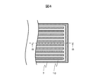
- FIG. 4 is a cross-sectional view taken along the line AA of FIG. 3 showing the flow path structure of the self-excited oscillating heat pipe in the present embodiment.
- FIG. 4 shows an example in which the self-excited oscillating heat pipe 7 has a flow path (sealed flow path) 10 in which the self-excited oscillating heat pipe 7 is partitioned by a partition wall, arranged in parallel and parallel, and the ends communicate with each other.
- the present invention is not limited to such a flow path structure, and the flow path 10 is configured as a plurality of closed flow paths that are partitioned by a partition wall and arranged in parallel in parallel, and each row does not communicate with each other. You may be. Further, the flow path 10 may be partially communicated.
- the cross-sectional dimensions of the flow paths 10 and the intervals between the flow paths are on the order of millimeters, and the flow path length is sufficiently longer than the flow path diameter.
- a predetermined amount of hydraulic fluid (not shown) is sealed in the flow path 10 of the self-excited oscillating heat pipe 7.
- hydrocarbons such as water, alcohols and butane
- hydrofluorocarbons such as water, alcohols and butane
- hydrofluoroethers such as water, alcohols and butane
- hydrofluoroolefins such as water, alcohols and butane
- perfluoroketones such as the working solution.
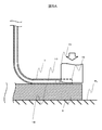
- FIG. 5A is a diagram showing a part of the manufacturing process of the self-excited oscillating heat pipe in the present embodiment
- FIG. 5B shows the structure of the crushed portion of the self-excited oscillating heat pipe in the present embodiment. It is a BB cross-sectional view of.
- the portion 18 near the end of the self-excited oscillating heat pipe 7 is fixed on the heat receiving plate 6 by brazing (first step).
- first step the lower surface of the end portion 19 (shown by the dotted line in FIG. 5A) of the self-excited oscillating heat pipe 7 is in close contact with the heat receiving plate 6.
- second step the working fluid is injected into the flow path 10 in the self-excited oscillating heat pipe 7 (second step).
- the heat receiving plate 6 is placed on the upper surface of the surface plate PL or the like, and the mold DI of the press machine or the like is brought close to the end 19 of the self-excited oscillating heat pipe 7 from above in FIG. 5A, and a high pressure is applied (No. Step 3).
- the end portion of the self-excited oscillating heat pipe 7 is crushed and plastically deformed, and the flow path 10 is sealed.
- the end of the crushed self-excited oscillating heat pipe 7 is designated as the crushed portion 11 (FIG. 5B).
- the traveling railway vehicle 2 is compared with the configuration in which the end of the self-excited oscillating heat pipe 7 is separated from the heat receiving plate 6.
- the stress generated at the joint between the heat receiving plate 6 and the self-excited oscillating heat pipe 7 can be suppressed to a small value when the vibration is received from the heat receiving plate 6.
- the joint area between the heat receiving plate 6 and the end portion of the self-excited oscillating heat pipe 7 is expanded, so that the heat transfer performance of the crushed portion 11 is improved.
- the above effect can be obtained only by crushing the end of the self-excited oscillating heat pipe 7 in contact with the heat receiving plate 6, so that the manufacturability is good.
- a refrigerant number R1336mzz (Z) which is a hydrofluoroolefin (hereinafter referred to as HFO)
- HFO hydrofluoroolefin
- the refrigerant number R1336mzz (Z) does not contain chlorine, it is chemically stable with respect to the aluminum alloy, and when the aluminum alloy is used as the material of the self-excited vibration heat pipe 7, the flow path The heat transfer performance can be maintained for a long period of time without corroding the self-excited vibration heat pipe 7 from the inside.
- Refrigerant number R1336mzz (Z) is nonflammable and has low toxicity, so even if a part of the flow path is damaged due to collision of flying objects and the working fluid is released into the atmosphere, safety is maintained. Can be secured.
- the refrigerant numbers R1224yd (Z), R1234yf, R1234ze (E), R1123, R1234ze (Z), R1336mzz (E), R1233zd (Z) or R1233zd (Z) ) And the like may be used. Since HFOs have a low global warming potential and ozone depletion potential, the impact on the environment is reduced even if some flow paths are damaged due to collision of flying objects and the working fluid is released into the atmosphere. be able to.
- FIG. 6 is a cross-sectional view taken along the line BB of FIG. 4 showing the structure of the crushed portion in the second embodiment.
- the protrusion 12 is provided at a position corresponding to the crushed portion 11 on the heat receiving plate 6 with respect to the first embodiment.
- Such a protrusion 12 can be formed by cutting out the heat receiving plate 6 by machining, or can be obtained by forming a ridge on the heat receiving plate 6 by welding or the like and then shaping it by machining.
- the end of the self-excited oscillating heat pipe 7 is pressed with high pressure from above by a press mold (see FIG. 5A) in a state of being in contact with the heat receiving plate 6 and the protrusion 12, and is crushed to crush the crushed portion 11. It is formed and the flow path 10 is sealed.
- the surface of the protrusion 12 shown in FIG. 6 in contact with the crushed portion 11 is formed of a curved surface, but the same effect can be obtained even if the protrusion 12 has a flat portion. Since the other configurations are the same as those in the above-described embodiment, duplicate description will be omitted.
- FIG. 7 is a cross-sectional view taken along the line BB of FIG. 4 showing the structure of the crushed portion in the third embodiment.
- a crushing member 14 which is a separate member from the heat receiving plate 6 is installed in the groove 13 provided on the heat receiving plate 6.
- the crushing member 14 made of an iron-based material such as SUS is fixed to the groove 13 by press fitting or the like to form a part of the heat receiving plate 6, and is cheaper than forming a protrusion on the heat receiving plate 6. Can be formed.
- the self-excited oscillating heat pipe 7 With the vicinity of the end of the self-excited oscillating heat pipe 7 in contact with the heat receiving plate 6 and the end in contact with the crushing member 14, the self-excited oscillating heat pipe 7 is pressed with high pressure from above by a press mold (see FIG. The crushed portion 11 is formed, and the flow path 10 is sealed.
- the surface of the crushed member 14 shown in FIG. 7 in contact with the crushed portion 11 is formed of a curved surface, but the same effect can be obtained even if the crushed member 14 has a flat portion.
- FIG. 8 is a cross-sectional view taken along the line BB of FIG. 4 showing a state in which the crushed member is removed from the groove of the crushed portion in the third embodiment.
- the crushing member 14 is removed from the groove 13 after the end portion of the self-excited oscillating heat pipe 7 is crushed.
- the crushing portion 11 is bent and folded until a part of the crushed portion is brought into close contact with the groove 13, so that the flying object or the like is crushed. It is possible to effectively suppress the contact with 11.
- FIG. 9 is a perspective view showing the structure of the welded sealing portion in the fourth embodiment.
- This embodiment has a structure in which the end portion of the self-excited oscillating heat pipe 7 is sealed by welding such as friction stir welding.
- the heat receiving plate 6 is provided with a groove 13 having a depth and width for accommodating the end portion of the self-excited oscillating heat pipe 7, and the end portion of the self-excited oscillating heat pipe 7 is installed in the groove 13.
- the rotating tool is brought close to the end of the self-excited vibration heat pipe 7, and the end of the self-excited vibration heat pipe 7 is pressed from the tool into the groove 13, and the self-excited vibration heat pipe 7 is applied.
- the end portion of the self-excited vibration heat pipe 7 can be welded to the heat receiving plate 6 by the frictional heat generated at the contact portion. Therefore, welding marks 15 remain on the end of the self-excited oscillating heat pipe 7 and the heat receiving plate 6.
- the same effect as that of the first embodiment can be obtained, and the end portion of the self-excited oscillating heat pipe 7 is welded to the heat receiving plate 6, so that stronger bonding is possible. Thermal conductivity also increases.
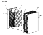
- FIG. 10A and 10B are cross-sectional views of the cooling device provided with the protective cover according to the fifth embodiment as viewed from the traveling direction of the railway vehicle.
- the cooling device of the present embodiment covers the entire self-excited oscillating heat pipe 7 and is provided with a housing-shaped protective cover 16 attached to the heat receiving plate 6.
- the protective cover 16 is provided with a plurality of ventilation holes 17 having predetermined dimensions on the projection surface of the self-excited vibration heat pipe 7 as viewed from the flow direction of the cooling air (the front-rear direction in the traveling direction of the railway vehicle).
- the traveling wind 8 (FIG. 1) generated during traveling of the railway vehicle 2 passes through the ventilation hole 17 and is supplied to the self-excited oscillating heat pipe 7 and the corrugated fin 9.
- the protective cover 16 By providing the protective cover 16 in this way, it is possible to suppress the collision of flying objects with the self-excited vibration heat pipe 7, and the reliability of the self-excited vibration heat pipe 7 is improved. Further, by providing the ventilation holes 17 having appropriate dimensions, it is possible to achieve both the strength of the protective cover 16 against flying objects and the ventilation of the traveling wind 8.
- the protective cover 16 shown in FIG. 10 is also provided with ventilation holes 17 on the upper and lower surfaces.
- the ventilation hole 17 is not provided on the surface 16a on the side opposite (opposing side) to the side in contact with the heat receiving plate 6. Since this surface 16a is orthogonal to the flow direction of the traveling wind 8 and the natural convection, it is preferable to prioritize the strength against flying objects over the amount of the cooling air taken in when the surface 16a is mounted on the railway vehicle 2. Reliability can be improved without impairing cooling performance. Further, by not providing an opening such as a ventilation hole 17 on the surface 16a, it is possible to prevent the cooling device 5 from being directly irradiated with sunlight and to reduce the temperature rise of the cooling device 5 in fine weather.
- the present invention is not limited to the above-described embodiment, and includes various modifications.
- the above-described embodiment has been described in detail in order to explain the present invention in an easy-to-understand manner, and is not necessarily limited to the one including all the described configurations. It is also possible to replace a part of the configuration in one embodiment with the configuration of another embodiment, and it is also possible to add the configuration of another embodiment to the configuration of one embodiment. .. Further, it is also possible to add / delete / replace a part of the configuration in each embodiment with another configuration.
- the present invention is applicable not only to railroad vehicles but also to cooling devices for moving objects such as automobiles, aircraft, and ships.
Landscapes
- Engineering & Computer Science (AREA)
- Life Sciences & Earth Sciences (AREA)
- Sustainable Development (AREA)
- Mechanical Engineering (AREA)
- Sustainable Energy (AREA)
- Power Engineering (AREA)
- Transportation (AREA)
- Physics & Mathematics (AREA)
- Thermal Sciences (AREA)
- General Engineering & Computer Science (AREA)
- Cooling Or The Like Of Semiconductors Or Solid State Devices (AREA)
- Cooling Or The Like Of Electrical Apparatus (AREA)
Priority Applications (1)
| Application Number | Priority Date | Filing Date | Title |
|---|---|---|---|
| JP2021524744A JP7273151B2 (ja) | 2019-06-06 | 2020-05-20 | 移動体用の冷却装置及び鉄道車両用の電力変換装置 |
Applications Claiming Priority (2)
| Application Number | Priority Date | Filing Date | Title |
|---|---|---|---|
| JP2019-106207 | 2019-06-06 | ||
| JP2019106207 | 2019-06-06 |
Publications (1)
| Publication Number | Publication Date |
|---|---|
| WO2020246240A1 true WO2020246240A1 (ja) | 2020-12-10 |
Family
ID=73652874
Family Applications (1)
| Application Number | Title | Priority Date | Filing Date |
|---|---|---|---|
| PCT/JP2020/019905 Ceased WO2020246240A1 (ja) | 2019-06-06 | 2020-05-20 | 移動体用の冷却装置、鉄道車両用の電力変換装置及び移動体用の冷却装置の製造方法 |
Country Status (2)
| Country | Link |
|---|---|
| JP (1) | JP7273151B2 (https=) |
| WO (1) | WO2020246240A1 (https=) |
Citations (5)
| Publication number | Priority date | Publication date | Assignee | Title |
|---|---|---|---|---|
| JPH06109383A (ja) * | 1992-09-29 | 1994-04-19 | Furukawa Electric Co Ltd:The | ヒ−トパイプ |
| JP2000074582A (ja) * | 1998-08-26 | 2000-03-14 | Showa Alum Corp | ヒートパイプの製造方法 |
| JP2016210263A (ja) * | 2015-05-07 | 2016-12-15 | 三菱電機株式会社 | 車両機器の冷却装置 |
| WO2017169969A1 (ja) * | 2016-03-31 | 2017-10-05 | 日本電気株式会社 | 冷却装置 |
| JP2018088744A (ja) * | 2016-11-28 | 2018-06-07 | 株式会社日立製作所 | 鉄道車両の電力変換装置 |
-
2020
- 2020-05-20 JP JP2021524744A patent/JP7273151B2/ja active Active
- 2020-05-20 WO PCT/JP2020/019905 patent/WO2020246240A1/ja not_active Ceased
Patent Citations (5)
| Publication number | Priority date | Publication date | Assignee | Title |
|---|---|---|---|---|
| JPH06109383A (ja) * | 1992-09-29 | 1994-04-19 | Furukawa Electric Co Ltd:The | ヒ−トパイプ |
| JP2000074582A (ja) * | 1998-08-26 | 2000-03-14 | Showa Alum Corp | ヒートパイプの製造方法 |
| JP2016210263A (ja) * | 2015-05-07 | 2016-12-15 | 三菱電機株式会社 | 車両機器の冷却装置 |
| WO2017169969A1 (ja) * | 2016-03-31 | 2017-10-05 | 日本電気株式会社 | 冷却装置 |
| JP2018088744A (ja) * | 2016-11-28 | 2018-06-07 | 株式会社日立製作所 | 鉄道車両の電力変換装置 |
Also Published As
| Publication number | Publication date |
|---|---|
| JP7273151B2 (ja) | 2023-05-12 |
| JPWO2020246240A1 (https=) | 2020-12-10 |
Similar Documents
| Publication | Publication Date | Title |
|---|---|---|
| US8593812B2 (en) | Heat exchanger, semiconductor device, method for manufacturing the heat exchanger, and method for manufacturing the semiconductor device | |
| JP6741561B2 (ja) | 鉄道車両の電力変換装置 | |
| JP4495021B2 (ja) | 車両搭載用ヒートシンク | |
| JP7537199B2 (ja) | 放熱器、冷却装置 | |
| JP4382891B2 (ja) | 扁平ヒートパイプとその製造方法 | |
| CN106549522A (zh) | 电机绕线框架结构 | |
| JP7133044B2 (ja) | 自励振動ヒートパイプ冷却器 | |
| WO1990009036A1 (en) | Method of producing heat pipe-type semiconductor cooling device | |
| US20050006078A1 (en) | Transmission oil cooler | |
| JP2016004805A (ja) | 液冷式冷却装置 | |
| JP2017059821A (ja) | 熱電発電装置及びその製造方法 | |
| JP7273151B2 (ja) | 移動体用の冷却装置及び鉄道車両用の電力変換装置 | |
| JP6837565B2 (ja) | 鉄道車両の電力変換装置および電力変換装置を搭載した鉄道車両 | |
| JP4265500B2 (ja) | 発熱体冷却装置 | |
| CN100513980C (zh) | 用于散热器的侧板 | |
| JP6623120B2 (ja) | 液冷式冷却装置 | |
| JP7010974B2 (ja) | 電力変換装置および自励振動ヒートパイプの製造方法 | |
| JP7430521B2 (ja) | 移動体用の冷却装置及び電力変換装置 | |
| CN107677155A (zh) | 一种平板热管散热器 | |
| JP2019021825A (ja) | 放熱器およびこれを用いた液冷式冷却装置 | |
| JP2005203732A (ja) | 冷却器 | |
| EP3352367B1 (en) | Thermoelectric power generation device | |
| CN113710982B (zh) | 自激振荡热管冷却装置和搭载有该冷却装置的铁道车辆 | |
| JP2019196850A (ja) | 冷却装置および当該冷却装置を備えた電力変換装置 | |
| JP7500277B2 (ja) | 自励振動ヒートパイプ、冷却装置及び電力変換装置 |
Legal Events
| Date | Code | Title | Description |
|---|---|---|---|
| 121 | Ep: the epo has been informed by wipo that ep was designated in this application |
Ref document number: 20818690 Country of ref document: EP Kind code of ref document: A1 |
|
| ENP | Entry into the national phase |
Ref document number: 2021524744 Country of ref document: JP Kind code of ref document: A |
|
| NENP | Non-entry into the national phase |
Ref country code: DE |
|
| 122 | Ep: pct application non-entry in european phase |
Ref document number: 20818690 Country of ref document: EP Kind code of ref document: A1 |