WO2020246201A1 - 車両用制御装置、車両用表示システム、及び車両用表示制御方法 - Google Patents
車両用制御装置、車両用表示システム、及び車両用表示制御方法 Download PDFInfo
- Publication number
- WO2020246201A1 WO2020246201A1 PCT/JP2020/018897 JP2020018897W WO2020246201A1 WO 2020246201 A1 WO2020246201 A1 WO 2020246201A1 JP 2020018897 W JP2020018897 W JP 2020018897W WO 2020246201 A1 WO2020246201 A1 WO 2020246201A1
- Authority
- WO
- WIPO (PCT)
- Prior art keywords
- image
- display
- interlocking
- displays
- images
- Prior art date
- Legal status (The legal status is an assumption and is not a legal conclusion. Google has not performed a legal analysis and makes no representation as to the accuracy of the status listed.)
- Ceased
Links
Images



Classifications
-
- B—PERFORMING OPERATIONS; TRANSPORTING
- B60—VEHICLES IN GENERAL
- B60K—ARRANGEMENT OR MOUNTING OF PROPULSION UNITS OR OF TRANSMISSIONS IN VEHICLES; ARRANGEMENT OR MOUNTING OF PLURAL DIVERSE PRIME-MOVERS IN VEHICLES; AUXILIARY DRIVES FOR VEHICLES; INSTRUMENTATION OR DASHBOARDS FOR VEHICLES; ARRANGEMENTS IN CONNECTION WITH COOLING, AIR INTAKE, GAS EXHAUST OR FUEL SUPPLY OF PROPULSION UNITS IN VEHICLES
- B60K35/00—Instruments specially adapted for vehicles; Arrangement of instruments in or on vehicles
- B60K35/20—Output arrangements, i.e. from vehicle to user, associated with vehicle functions or specially adapted therefor
- B60K35/21—Output arrangements, i.e. from vehicle to user, associated with vehicle functions or specially adapted therefor using visual output, e.g. blinking lights or matrix displays
- B60K35/22—Display screens
-
- B—PERFORMING OPERATIONS; TRANSPORTING
- B60—VEHICLES IN GENERAL
- B60K—ARRANGEMENT OR MOUNTING OF PROPULSION UNITS OR OF TRANSMISSIONS IN VEHICLES; ARRANGEMENT OR MOUNTING OF PLURAL DIVERSE PRIME-MOVERS IN VEHICLES; AUXILIARY DRIVES FOR VEHICLES; INSTRUMENTATION OR DASHBOARDS FOR VEHICLES; ARRANGEMENTS IN CONNECTION WITH COOLING, AIR INTAKE, GAS EXHAUST OR FUEL SUPPLY OF PROPULSION UNITS IN VEHICLES
- B60K35/00—Instruments specially adapted for vehicles; Arrangement of instruments in or on vehicles
- B60K35/20—Output arrangements, i.e. from vehicle to user, associated with vehicle functions or specially adapted therefor
- B60K35/29—Instruments characterised by the way in which information is handled, e.g. showing information on plural displays or prioritising information according to driving conditions
-
- B—PERFORMING OPERATIONS; TRANSPORTING
- B60—VEHICLES IN GENERAL
- B60K—ARRANGEMENT OR MOUNTING OF PROPULSION UNITS OR OF TRANSMISSIONS IN VEHICLES; ARRANGEMENT OR MOUNTING OF PLURAL DIVERSE PRIME-MOVERS IN VEHICLES; AUXILIARY DRIVES FOR VEHICLES; INSTRUMENTATION OR DASHBOARDS FOR VEHICLES; ARRANGEMENTS IN CONNECTION WITH COOLING, AIR INTAKE, GAS EXHAUST OR FUEL SUPPLY OF PROPULSION UNITS IN VEHICLES
- B60K35/00—Instruments specially adapted for vehicles; Arrangement of instruments in or on vehicles
- B60K35/80—Arrangements for controlling instruments
-
- G—PHYSICS
- G06—COMPUTING OR CALCULATING; COUNTING
- G06F—ELECTRIC DIGITAL DATA PROCESSING
- G06F3/00—Input arrangements for transferring data to be processed into a form capable of being handled by the computer; Output arrangements for transferring data from processing unit to output unit, e.g. interface arrangements
- G06F3/14—Digital output to display device ; Cooperation and interconnection of the display device with other functional units
- G06F3/1423—Digital output to display device ; Cooperation and interconnection of the display device with other functional units controlling a plurality of local displays, e.g. CRT and flat panel display
- G06F3/1431—Digital output to display device ; Cooperation and interconnection of the display device with other functional units controlling a plurality of local displays, e.g. CRT and flat panel display using a single graphics controller
-
- G—PHYSICS
- G06—COMPUTING OR CALCULATING; COUNTING
- G06T—IMAGE DATA PROCESSING OR GENERATION, IN GENERAL
- G06T11/00—Two-dimensional [2D] image generation
- G06T11/60—Creating or editing images; Combining images with text
-
- G—PHYSICS
- G06—COMPUTING OR CALCULATING; COUNTING
- G06T—IMAGE DATA PROCESSING OR GENERATION, IN GENERAL
- G06T13/00—Animation
-
- G—PHYSICS
- G06—COMPUTING OR CALCULATING; COUNTING
- G06T—IMAGE DATA PROCESSING OR GENERATION, IN GENERAL
- G06T3/00—Geometric image transformations in the plane of the image
- G06T3/60—Rotation of whole images or parts thereof
-
- G—PHYSICS
- G09—EDUCATION; CRYPTOGRAPHY; DISPLAY; ADVERTISING; SEALS
- G09G—ARRANGEMENTS OR CIRCUITS FOR CONTROL OF INDICATING DEVICES USING STATIC MEANS TO PRESENT VARIABLE INFORMATION
- G09G5/00—Control arrangements or circuits for visual indicators common to cathode-ray tube indicators and other visual indicators
- G09G5/14—Display of multiple viewports
-
- H—ELECTRICITY
- H04—ELECTRIC COMMUNICATION TECHNIQUE
- H04N—PICTORIAL COMMUNICATION, e.g. TELEVISION
- H04N5/00—Details of television systems
- H04N5/66—Transforming electric information into light information
-
- B—PERFORMING OPERATIONS; TRANSPORTING
- B60—VEHICLES IN GENERAL
- B60K—ARRANGEMENT OR MOUNTING OF PROPULSION UNITS OR OF TRANSMISSIONS IN VEHICLES; ARRANGEMENT OR MOUNTING OF PLURAL DIVERSE PRIME-MOVERS IN VEHICLES; AUXILIARY DRIVES FOR VEHICLES; INSTRUMENTATION OR DASHBOARDS FOR VEHICLES; ARRANGEMENTS IN CONNECTION WITH COOLING, AIR INTAKE, GAS EXHAUST OR FUEL SUPPLY OF PROPULSION UNITS IN VEHICLES
- B60K2360/00—Indexing scheme associated with groups B60K35/00 or B60K37/00 relating to details of instruments or dashboards
- B60K2360/18—Information management
- B60K2360/182—Distributing information between displays
-
- B—PERFORMING OPERATIONS; TRANSPORTING
- B60—VEHICLES IN GENERAL
- B60K—ARRANGEMENT OR MOUNTING OF PROPULSION UNITS OR OF TRANSMISSIONS IN VEHICLES; ARRANGEMENT OR MOUNTING OF PLURAL DIVERSE PRIME-MOVERS IN VEHICLES; AUXILIARY DRIVES FOR VEHICLES; INSTRUMENTATION OR DASHBOARDS FOR VEHICLES; ARRANGEMENTS IN CONNECTION WITH COOLING, AIR INTAKE, GAS EXHAUST OR FUEL SUPPLY OF PROPULSION UNITS IN VEHICLES
- B60K2360/00—Indexing scheme associated with groups B60K35/00 or B60K37/00 relating to details of instruments or dashboards
- B60K2360/18—Information management
- B60K2360/184—Displaying the same information on different displays
-
- B—PERFORMING OPERATIONS; TRANSPORTING
- B60—VEHICLES IN GENERAL
- B60K—ARRANGEMENT OR MOUNTING OF PROPULSION UNITS OR OF TRANSMISSIONS IN VEHICLES; ARRANGEMENT OR MOUNTING OF PLURAL DIVERSE PRIME-MOVERS IN VEHICLES; AUXILIARY DRIVES FOR VEHICLES; INSTRUMENTATION OR DASHBOARDS FOR VEHICLES; ARRANGEMENTS IN CONNECTION WITH COOLING, AIR INTAKE, GAS EXHAUST OR FUEL SUPPLY OF PROPULSION UNITS IN VEHICLES
- B60K35/00—Instruments specially adapted for vehicles; Arrangement of instruments in or on vehicles
- B60K35/80—Arrangements for controlling instruments
- B60K35/81—Arrangements for controlling instruments for controlling displays
-
- G—PHYSICS
- G09—EDUCATION; CRYPTOGRAPHY; DISPLAY; ADVERTISING; SEALS
- G09G—ARRANGEMENTS OR CIRCUITS FOR CONTROL OF INDICATING DEVICES USING STATIC MEANS TO PRESENT VARIABLE INFORMATION
- G09G2340/00—Aspects of display data processing
- G09G2340/04—Changes in size, position or resolution of an image
- G09G2340/0407—Resolution change, inclusive of the use of different resolutions for different screen areas
- G09G2340/0435—Change or adaptation of the frame rate of the video stream
-
- G—PHYSICS
- G09—EDUCATION; CRYPTOGRAPHY; DISPLAY; ADVERTISING; SEALS
- G09G—ARRANGEMENTS OR CIRCUITS FOR CONTROL OF INDICATING DEVICES USING STATIC MEANS TO PRESENT VARIABLE INFORMATION
- G09G2340/00—Aspects of display data processing
- G09G2340/04—Changes in size, position or resolution of an image
- G09G2340/0492—Change of orientation of the displayed image, e.g. upside-down, mirrored
-
- G—PHYSICS
- G09—EDUCATION; CRYPTOGRAPHY; DISPLAY; ADVERTISING; SEALS
- G09G—ARRANGEMENTS OR CIRCUITS FOR CONTROL OF INDICATING DEVICES USING STATIC MEANS TO PRESENT VARIABLE INFORMATION
- G09G2340/00—Aspects of display data processing
- G09G2340/10—Mixing of images, i.e. displayed pixel being the result of an operation, e.g. adding, on the corresponding input pixels
-
- G—PHYSICS
- G09—EDUCATION; CRYPTOGRAPHY; DISPLAY; ADVERTISING; SEALS
- G09G—ARRANGEMENTS OR CIRCUITS FOR CONTROL OF INDICATING DEVICES USING STATIC MEANS TO PRESENT VARIABLE INFORMATION
- G09G2380/00—Specific applications
- G09G2380/10—Automotive applications
Definitions
- the present disclosure relates to a vehicle control device, a vehicle display system, and a vehicle display control method.
- Patent Document 1 discloses a technique for displaying an opening animation on a display arranged in a vehicle interior when an in-vehicle system is activated. Further, in recent years, a plurality of displays have been provided in the vehicle interior. Conventionally, with respect to a plurality of displays provided in a vehicle interior, processing for display has been individually performed by a control device for each display.
- the processing for display is individually performed by the control device for each display. Therefore, when a situation occurs in which some control devices must devote resources to processing other than display, the processing speed of the control device decreases, and the timing between displays that should be linked on multiple displays shifts. Will occur. As a result, the user feels uncomfortable with the display linked between the plurality of displays. In particular, when the display is an animation, the user is more likely to feel a sense of discomfort due to the timing difference between the displays that should be linked on the plurality of displays.
- One purpose of this disclosure is to make it possible to make it difficult for the user to feel a sense of discomfort due to a difference in display timing between the plurality of displays when the multiple displays provided in the vehicle interior are linked to each other. It is an object of the present invention to provide a vehicle control device, a vehicle display system, and a vehicle display control method.
- the vehicle control device of the present disclosure is a vehicle control device that controls the display of a plurality of displays provided in the interior of the vehicle, and displays the displays in conjunction with each other.
- a display processing unit that performs output preprocessing, which is a process for converting linked images, which are images for each display, into information that can be output to the display, and a plurality of displays in which output preprocessing is performed by a common display processing unit. It is provided with an image output unit that outputs interlocking images for each of the above to the corresponding display.
- the vehicle display control method of the present disclosure is a vehicle display control method for controlling the display of a plurality of displays provided in a vehicle interior, and is interlocked between the plurality of displays.
- the common display processing unit For the linked image, which is an image for each display to be displayed, the common display processing unit performs the output preprocessing, which is the processing to make the information output to the display, and the common display processing unit performs the output preprocessing.
- the linked images for each of the plurality of displays are output to the corresponding displays by the image output unit that outputs the linked images to the displays.
- the display processing unit performs output preprocessing as information that can be output to the display for the linked image, which is an image for each display to be linked and displayed between a plurality of displays. Therefore, as compared with performing the output preprocessing individually by the control device for each display, it is possible to suppress the timing deviation of the output preprocessing for the interlocking image for each display. Therefore, when the image output unit outputs the interlocking image for each of the plurality of displays to which the common display processing unit performs the output preprocessing, the output timing shift is also accompanied by the output timing deviation. It becomes possible to suppress it. This makes it possible to suppress a shift in the display timing of the linked images on each of the plurality of displays. As a result, when displaying in conjunction with a plurality of displays provided in the vehicle interior, it is possible to make it difficult for the user to feel a sense of discomfort due to a shift in display timing between the plurality of displays.
- the vehicle display system of the present disclosure includes a plurality of displays provided in the interior of the vehicle and the above-mentioned vehicle control device that controls the display of the plurality of displays.
- the vehicle control device when displaying in conjunction with a plurality of displays provided in the vehicle interior, the user feels uncomfortable due to a shift in display timing between the plurality of displays. It becomes possible to make it difficult to squeeze.
- the vehicle display system 1 is used in a vehicle.
- the vehicle display system 1 includes an integrated ECU 10, a center information display (hereinafter, CID) 20, and a meter multi-information display (hereinafter, meter MID) 30.
- CID center information display
- meter MID meter multi-information display
- the CID20 is a display provided in the center cluster in the interior of the vehicle.
- a display capable of drawing an image may be used.
- a liquid crystal display, an organic EL display, or the like can be used.
- the CID 20 mainly displays information on multimedia functions such as navigation information and audio information.
- the navigation information is information related to the navigation function, such as a route guidance image.
- the audio information is an image or the like related to the operation of the audio device. Opening display information, air conditioning information, and the like are also displayed on the CID 20.
- the opening display information is an image (hereinafter referred to as an opening image) related to the opening effect when the vehicle is started.
- the air conditioning information is an image or the like related to the operation of the air conditioning equipment.
- the meter MID30 is a display provided in front of the driver's seat in the interior of the vehicle.
- the meter MID30 may be configured to be provided on the meter panel.
- a display capable of drawing an image may be used.
- a liquid crystal display, an organic EL display, or the like can be used.
- the meter MID 30 mainly displays information on safety and security functions such as meter information.
- the meter information is an image or the like related to the meter display.
- the meter MID30 also displays opening display information, simplified navigation information, and the like.
- the opening display information is the above-mentioned opening image or the like, and the opening image displayed on the meter MID 30 is not the same as the opening image displayed on the CID 20.
- the simplified navigation information is information that is simplified more than the navigation information displayed by the CID 20, and is, for example, a simplified route guidance image or the like.
- the CID 20 and the meter MID 30 may have the same screen resolution, but in the present embodiment, the screen resolutions of the CID 20 and the meter MID 30 may be different from each other.
- the screen resolution is the number of pixels displayed on the display, and is represented by the number of pixels in each of the vertical and horizontal directions.
- the screen resolution of the CID 20 has a larger number of pixels than the screen resolution of the meter MID 30 will be described as an example.
- the CID 20 and the meter MID 30 may be configured to have the same frame rate when performing animation display, but in the present embodiment, the following description will be made assuming that the frame rates are different from each other.
- the frame rate is the number of images per unit time when displaying an animation.
- the frame rate may be represented by frames per second (fps: frames per second), which represents the number of images per second.
- fps frames per second
- the case where the frame rate of the CID 20 is three times the frame rate of the meter MID 30 will be described as an example.
- the CID 20 corresponds to the first display
- the meter MID 30 corresponds to the second display.
- the integrated ECU 10 is an ECU (Electronic Control Unit) that integrates the function of controlling the CID 20 and the function of controlling the meter MID 30.
- the integrated ECU 10 is connected to the CID 20 and the meter MID 30, and causes the CID 20 and the meter MID 30 to draw and display various images.
- the integrated ECU 10 is also connected to the in-vehicle LAN, and information from a sensor connected to the in-vehicle LAN, another ECU, or the like is input.
- the image drawn by the integrated ECU 10 on the CID 20 and the meter MID 30 corresponds to the output information of the integrated ECU 10.
- the information input to the integrated ECU 10 via the in-vehicle LAN corresponds to the input information of the integrated ECU 10.
- the input information includes vehicle information such as vehicle speed and mileage, digital TV image information, smartphone cooperation information linked with a smartphone, and the like.
- the integrated ECU 10 has a configuration in which input information and output information are collectively managed, and the input source and output destination of various information can be freely rearranged.
- the integrated ECU 10 is mainly composed of, for example, a processor, a memory, an I / O, and a microcomputer (hereinafter, a microcomputer) provided with a bus connecting these.
- the integrated ECU 10 executes various processes related to displaying an image on the CID 20 and the meter MID 30 by executing a control program stored in the memory.
- the integrated ECU 10 displays an image in conjunction with the CID 20 and the meter MID 30.
- the integrated ECU 10 corresponds to a vehicle control device.
- the memory referred to here is a non-transitory tangible storage medium that stores programs and data that can be read by a computer non-temporarily. Further, the non-transitional substantive storage medium is realized by a semiconductor memory, a magnetic disk, or the like. The details of the integrated ECU 10 will be described below.
- the schematic configuration shown in FIG. 2 is a configuration housed in one housing.
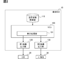
- the integrated ECU 10 includes a microcomputer 100, a mixed image storage unit 110, a first image output unit 120, and a second image output unit 130.
- a part or all of the functions executed by the integrated ECU 10 may be configured in hardware by one or a plurality of ICs or the like.
- the mixed image storage unit 110 stores an image (hereinafter, mixed image) in which images for each of these displays (hereinafter, interlocking image), which are interlocked and displayed between the CID 20 and the meter MID 30, are combined in one frame. doing.
- the mixed image storage unit 110 may be a non-volatile memory. In the present embodiment, it is assumed that the interlocking image for the CID 20 and the interlocking image for the meter MID 30 are combined and stored in the mixed image storage unit 110 in advance.
- Interlocking here refers to making the displayed objects appear to move in synchronization between the CID20 and the meter MID30.
- interlocking means that the displayed object is displayed between the CID 20 and the meter MID 30 so as to gradually move from one to the other. Further, the displayed object may be displayed between the CID 20 and the meter MID 30 so as to gradually expand from one to the other. Alternatively, the CID 20 and the meter MID 30 may be displayed so that the user can see that the other object has changed in response to the change of one object.
- the interlocking referred to here may be to perform the same deformation and rotation of the image between the CID 20 and the meter MID 30, or may be a configuration not limited to this.
- the linked image is a still image in chronological order for displaying the animation.
- the mixed image storage unit 110 frames of mixed images are stored side by side in chronological order for displaying this animation.
- the opening animation a case where the opening image is interlocked and displayed as an animation between the CID 20 and the meter MID 30 will be described as an example.
- the animation of the opening image will be referred to as the opening animation.
- FIG. 3 shows an example in which the screen resolution of the linked image of the CID 20 and the linked image of the meter MID 30 are equal for convenience.
- the interlocking images may be arranged side by side in one frame with the information of the non-display area sandwiched between them.
- the information in the non-display area is linked without being sandwiched between them. It is preferable that the images are arranged side by side in one frame and combined.
- the CID 20 and the meter MID 30 are combined so that the size of the mixed image in one frame is minimized. It is preferable that the interlocking image is synthesized by rotating a part of the interlocking images corresponding to.
- the linked image with a smaller number of pixels on the long side is rotated so that the long side of the linked image with a smaller number of pixels on the long side is aligned with the short side of the linked image with a larger number of pixels on the long side.
- the interlocking images for each of the CID 20 and the meter MID 30 may be combined in one frame.
- the interlocking image of the meter MID30 is rotated 90 degrees clockwise and synthesized so that the long side of the interlocking image of the meter MID30 is aligned with the short side of the interlocking image of the CID20. It may be configured as such.
- the interlocking image is not arranged in one frame as compared with the case where the short sides of the interlocking images corresponding to the CID 20 and the meter MID 30 are simply arranged side by side and combined. It is possible to keep the used area small. Therefore, when reading the mixed image from the mixed image storage unit 110, it is possible to reduce unnecessary reading of the unused area and increase the reading speed of the mixed image.
- the mixed image is preferably combined for each number of frames corresponding to the frame rate of the display having the highest frame rate.
- the frame rate of the CID 20 is three times that of the meter MID 30, it is assumed that the mixed images are synthesized for each of the number of frames corresponding to the frame rate of the CID 20.
- the interlocking image for the meter MID30 having a lower frame rate is combined with the interlocking image for the CID20 for each number of frames according to the ratio of the frame rate to the CID20 having the highest frame rate to form a mixed image. It may be configured as such.
- the frame rate of the CID 20 is three times that of the meter MID 30, so as shown in FIG. 6, the interlocking image of the meter MID 30 is combined with the interlocking image of the CID 20 every three frames and mixed. It is assumed that it is an image.
- the interlocking image of the meter MID 30 is combined as empty data to form a mixed image.
- the interlocking image of the meter MID 30 is a mixed image that is not combined.
- the area of one frame may be uniformly fixed even when the interlocking image of the meter MID 30 is combined.
- the interlocking image of the meter MID30 having a lower frame rate may be combined with the interlocking image of the CID20 having the highest frame rate over the entire frame to form a mixed image.
- the microcomputer 100 includes a display processing unit 101 as a functional block.
- the display processing unit 101 performs output preprocessing, which is a process of converting the linked image to be displayed in conjunction between the CID 20 and the meter MID 30 into information that can be output to the display. It is assumed that the display processing unit 101 is common to the CID 20 and the meter MID 30. This can be rephrased as the microcomputer that performs output preprocessing is common to a plurality of displays.
- the display processing unit 101 performs output preprocessing on the mixed image in which the interlocking images of the CID 20 and the meter MID 30 are combined in one frame, so that the interlocking image of each of the CID 20 and the meter MID 30 is performed. Is output preprocessed.
- the output pre-processing there is a process of reading the mixed image stored in the mixed image storage unit 110 and expanding it in the memory of the microcomputer 100.
- This memory is, for example, a graphic memory.
- an output command for outputting (that is, drawing) an interlocking image corresponding to each display of the mixed images expanded in the graphic memory is sent to the first image output unit 120 and the second image output unit 130.
- the order in which the display processing unit 101 issues output commands to the first image output unit 120 and the second image output unit 130 corresponds to the priority of the order in which the first image output unit 120 and the second image output unit 130 output to the display. doing.
- the display processing unit 101 is set to issue an output command to both the first image output unit 120 and the second image output unit 130 at one time. That is, the priority that the first image output unit 120 outputs to the CID 20 and the priority that the second image output unit 130 outputs to the meter MID 30 are set to be equal. As a result, the interlocking image for the CID 20 and the interlocking image for the meter MID30 included in the mixed image are output to the corresponding displays substantially simultaneously by the first image output unit 120 and the second image output unit 130. become. Therefore, when displaying in conjunction with a plurality of displays provided in the vehicle interior, it is possible to make it difficult for the user to feel a sense of discomfort due to a difference in display timing between the plurality of displays.
- the display processing unit 101 performs output preprocessing for each frame of the mixed images stored in the mixed image storage unit 110 arranged in chronological order in order to display the animation, one frame at a time in this time series. Perform sequentially.
- the first image output unit 120 outputs an interlocking image of the CID 20 that has been preprocessed by the display processing unit 101 to the CID 20.
- the first image output unit 120 designates an area of the interlocking image corresponding to the CID 20 among the mixed images preprocessed by the display processing unit 101, and outputs the interlocking image about the CID 20 to the CID 20. ..
- the first image output unit 120 may be able to specify the area of the interlocking image corresponding to the CID 20 by having information on the range of the interlocking image about the CID 20 in the frame area in advance.
- the first image output unit 120 has, for example, having a correspondence relationship between the coordinates in the frame area and the coordinates of the screen of the CID 20 in advance, so that the interlocking image for the CID 20 is rotated and synthesized in the mixed image. Even in this case, it is sufficient to enable the display in the orientation before rotation.
- an IC may be used as the first image output unit 120.
- the second image output unit 130 outputs an interlocking image of the meter MID 30 for which output preprocessing has been performed by the display processing unit 101 to the meter MID 30.
- the second image output unit 130 designates an area of the interlocking image corresponding to the meter MID 30 among the mixed images preprocessed by the display processing unit 101, and displays the interlocking image of the meter MID 30 with the meter MID 30. Output to.
- the second image output unit 130 may be able to specify the area of the interlocking image corresponding to the meter MID 30 by having the information of the range of the interlocking image about the meter MID 30 in the frame area in advance.
- the second image output unit 130 has, for example, a correspondence relationship between the coordinates in the frame area and the coordinates of the screen of the meter MID 30 in advance, so that the interlocking image of the meter MID 30 is rotated and synthesized in the mixed image. Even if it is, it may be possible to display it in the direction before rotation.
- an IC may be used as the second image output unit 130.
- the first image output unit 120 and the second image output unit 130 are CID20 of the mixed images in which the output preprocessing of the mixed image is sequentially performed frame by frame in the display processing unit 101. And the area of the interlocking image corresponding to each of the meter MID30 is designated, and the interlocking image for each of the CID 20 and the meter MID 30 is sequentially output to the CID 20 and the meter MID 30, respectively.
- animation is displayed at each of the CID 20 and the meter MID 30. Therefore, when performing animation display linked between a plurality of displays provided in the vehicle interior, it is possible to make it difficult for the user to feel a sense of discomfort due to a shift in display timing between the plurality of displays.
- the interlocking image is included. Is not output to that display. As an example, the following may be performed.
- the first image output unit 120 whose output destination is the CID 20 having the highest frame rate corresponds to the CID 20 of the mixed images in which the output pre-processing is sequentially performed by the display processing unit 101.
- the area of the interlocking image may be designated, and the interlocking image may be sequentially output to the CID 20.
- the second image output unit 130 whose output destination is the meter MID30 having a lower frame rate is among the mixed images in which the output preprocessing is performed for each number of frames corresponding to the ratio of the frame rate of the meter MID30 to the CID20.
- the area of the interlocking image corresponding to the meter MID30 may be designated, and the interlocking image may be sequentially output to the meter MID30.
- the second image output unit 130 specifies the area of the interlocking image corresponding to the meter MID30 of the mixed images to which the output preprocessing is performed every three frames, and measures the interlocking image. It is sequentially output to MID30.
- the second image output unit 130 receives the above-mentioned output command from the display processing unit 101 for each frame, whereas the output command is obeyed by a number corresponding to the ratio of the frame rate of the meter MID 30 to the CID 20. It may be frame by frame.
- the animation display linked between the plurality of displays provided in the vehicle interior can be displayed while eliminating the waste of outputting the linked image that cannot be displayed on the displays. , It is possible to suppress the deviation of the display timing.
- FIG. 7 a case where the opening animation is displayed will be described as an example.
- the flowchart of FIG. 7 may be started when the activation trigger is detected.
- the start trigger may be, for example, when the switch for starting the internal combustion engine or the motor generator of the own vehicle is turned on.
- step S1 the display processing unit 101 reads out one frame of the mixed images of a plurality of frames for the opening animation stored in the mixed image storage unit 110 in chronological order, and the memory of the microcomputer 100. Expand to.
- step S2 the display processing unit 101 issues an output command to both the first image output unit 120 and the second image output unit 130 at one time.
- step S3 if the mixed image read in S1 includes the interlocking image of the meter MID30 (YES in S3), the process proceeds to step S4.
- the process proceeds to step S4.
- the frame read in S1 may be divided according to the number of frames after the start of reading the frame. In the example of the present embodiment, it is assumed that the interlocking image of the meter MID 30 is included in the mixed image every three frames after the first frame.
- step S4 the first image output unit 120 specifies the region of the interlocking image corresponding to CID20 among the mixed images subjected to the output preprocessing in S1 to S2, and outputs the interlocking image about CID20 to CID20. Is output to, and the process proceeds to step S6. Further, the second image output unit 130 specifies the area of the interlocking image corresponding to the meter MID30 among the mixed images subjected to the output preprocessing in S1 to S2, and displays the interlocking image of the meter MID30. Output to MID30. Since the display processing unit 101 issues an output command to the first image output unit 120 and the second image output unit 130 once, the output processing is performed by the first image output unit 120 and the second image output unit 130. , Will be done at almost the same timing.
- step S5 the first image output unit 120 specifies the region of the interlocking image corresponding to CID20 among the mixed images subjected to the output preprocessing in S1 to S2, and outputs the interlocking image about CID20 to CID20. Is output to, and the process proceeds to step S6.
- the second image output unit 130 does not perform output processing.
- step S6 when the processing is completed for all the frames out of the plurality of frames for the opening animation (YES in S6), the interlocking display control related processing is ended. On the other hand, when there are still frames that have not been processed (NO in S6), the process returns to S1 and the remaining frames are processed.
- the explanation was given by taking the case of displaying the opening animation as an example, but it is not necessarily limited to this. It may be applied when displaying an animation other than the opening animation.
- the common display processing unit 101 performs pre-output processing for the interlocking image of the CID 20 and the interlocking image of the meter MID 30 to be interlocked and displayed between the CID 20 and the meter MID 30. Do. Therefore, as compared with performing the output preprocessing individually by the control device for the CID 20 and the control device for the meter MID 30, it is possible to suppress the timing deviation of the output preprocessing for each interlocking image.
- the pre-output processing is performed on the mixed image in which the interlocking images of the CID 20 and the meter MID 30 to be interlocked with each other are combined in one frame, the timing deviation of the pre-output processing for each interlocking image is more easily suppressed. Will be possible.
- the display processing unit 101 issues an output command to both the first image output unit 120 and the second image output unit 130 at once, the first image output unit 120 and the second image output unit 130 are linked to each other. It is possible to suppress the deviation of the output of the interlocking image between the CID 20 and the meter MID 30 to be made smaller. As a result, it is possible to suppress a deviation in the display timing of the interlocking image between the CID 20 and the meter MID 30. As a result, when displaying in conjunction with a plurality of displays provided in the vehicle interior, it is possible to make it difficult for the user to feel a sense of discomfort due to a shift in display timing between the plurality of displays.
- Embodiment 2 In the first embodiment, the configuration in which the output preprocessing is performed using the mixed images stored in advance in the non-volatile memory is shown, but the present invention is not necessarily limited to this. For example, it may be configured to sequentially synthesize mixed images from independent interlocking image files and perform output preprocessing (hereinafter, embodiment 2).
- the vehicle display system 1 of the second embodiment is the same as the vehicle display system 1 of the first embodiment except that the integrated ECU 10a is included instead of the integrated ECU 10.
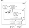
- the integrated ECU 10a includes a microcomputer 100a, a first image output unit 120, a second image output unit 130, a first image storage unit 140, and a second image storage unit 150.
- Embodiments of the integrated ECU 10a except that the microcomputer 100a is provided instead of the microcomputer 100, the mixed image storage unit 110 is not provided, and the first image storage unit 140 and the second image storage unit 150 are provided. It is the same as the integrated ECU 10 of 1.
- This integrated ECU 10a also corresponds to a vehicle control device.
- the first image storage unit 140 stores the interlocking image of the CID20 among the interlocking images to be interlocked and displayed between the CID20 and the meter MID30.
- interlocking images for displaying the animation on the CID 20 are stored side by side in chronological order.
- the first image storage unit 140 may be a non-volatile memory. In the present embodiment, it is assumed that the first image storage unit 140 stores the linked image of the CID 20 in advance.
- the second image storage unit 150 stores the interlocking image of the meter MID30 among the interlocking images to be interlocked and displayed between the CID 20 and the meter MID 30.
- interlocking images for displaying the animation on the meter MID 30 are stored side by side in chronological order.
- the second image storage unit 150 may be a non-volatile memory. In the present embodiment, it is assumed that the second image storage unit 150 stores the interlocking image of the meter MID 30 in advance.
- the microcomputer 100a includes a display processing unit 101a, a compositing unit 102, and a mixed image storage unit 103 as functional blocks.
- a part or all of the functional blocks included in the microcomputer 100a may be realized by executing software by a processor and a combination of hardware members.
- the compositing unit 102 synthesizes the interlocking images to be interlocked among the interlocking images independent for each of the plurality of displays in one frame to synthesize the mixed image.
- the synthesizing unit 102 sequentially reads out the interlocking images to be interlocked from each of the first image storage unit 140 and the second image storage unit 150, synthesizes them in one frame, and synthesizes the mixed images.
- the linked images are stored in advance in the first image storage unit 140 and the second image storage unit 150 so that the linked images to be linked can be read out in order by reading them in chronological order. And it is sufficient. Further, the linked images to be linked may be configured to correspond with each other by, for example, an image file number or the like.
- the compositing unit 102 sequentially synthesizes the mixed images and stores them in the mixed image storage unit 103.
- the mixed image storage unit 103 may be, for example, a volatile memory.
- the synthesizing unit 102 puts the interlocking image for the CID 20 and the interlocking image for the meter MID 30 in one frame without sandwiching the information in the non-display area. It is preferable to synthesize them side by side. As an example, when a non-display area is set around the linked image, the non-display area may be excluded and combined.
- the compositing unit 102 is a combination in which the size of the mixed image in one frame is minimized when the screen resolutions of the interlocking images corresponding to the CID 20 and the meter MID 30 are different. It is preferable to rotate some of the interlocking images among the interlocking images corresponding to the CID 20 and the meter MID 30 to synthesize the interlocking images. As an example, the interlocking image with a smaller number of pixels on the long side is rotated so that the long side of the interlocking image with a smaller number of pixels on the long side is aligned with the short side of the interlocking image having a larger number of pixels on the long side. Then, the interlocking images for each of the CID 20 and the meter MID 30 may be combined in one frame.
- the display processing unit 101a is rotated to the side of the first image output unit 120 and the second image output unit 130 that outputs the rotated interlocking image.
- the coordinate conversion information may be output in addition to the output command. According to this, on the side that outputs the rotated interlocking image, it is possible to return the rotated interlocking image to the original direction and draw it by using the information of the coordinate transformation by the rotation.
- the synthesizing unit 102 interlocks images for each number of frames according to the frame rate of the display having the highest frame rate. Is preferably synthesized.
- the interlocking image for the meter MID 30 having a lower frame rate may be combined with the interlocking image for the CID 20 for each number of frames according to the ratio of the frame rate to the CID 20 having the highest frame rate.
- the interlocking image of the meter MID 30 may be combined as empty data.
- the display processing unit 101a is configured to output to the second image output unit 130 a number of information corresponding to the ratio of the frame rate of the meter MID 30 to the CID 20 having the highest frame rate in addition to the output command. Just do it.
- the second image output unit 130 can perform output processing for each of the numbers by using the information of the number corresponding to the ratio of the frame rate of the meter MID 30 to the CID 20.
- the display processing unit 101a is the same as the display processing unit 101 of the first embodiment, except that the destination for reading the mixed image is the mixed image storage unit 103 instead of the mixed image storage unit 110.
- the first embodiment is to perform the output preprocessing using the mixed images stored in advance in the non-volatile memory, or to perform the output preprocessing by sequentially synthesizing the mixed images. Since the configuration is the same except for the differences, as in the first embodiment, when the plurality of displays provided in the vehicle interior are linked to each other, a sense of discomfort due to a difference in display timing between the plurality of displays is felt. It becomes possible to make it difficult for the user to hold. Further, according to the configuration of the second embodiment, it is possible to reduce the trouble of synthesizing the mixed images in advance and storing them in the non-volatile memory.
- the vehicle display system 1 includes two displays, a CID 20 and a meter MID 30, but the present invention is not limited to this.
- a display other than the CID 20 and the meter MID 30 may be included in the vehicle display system 1.
- a head-up display may be used instead of the meter MID30.
- the number of displays included in the vehicle display system 1 may be three or more.
- the size of the mixed image in one frame is the minimum when the screen resolutions of the linked images corresponding to the respective displays are different. It is preferable that some of the interlocking images corresponding to the respective displays are rotated so that the interlocking images are combined so as to form a combination.
- the interlocking image is a still image in chronological order for displaying the animation
- it may be a still image not used for animation that should be displayed at the same timing on a plurality of displays. Even in this case, by suppressing the shift in the display timing of the still image that should be displayed at the same timing, it is possible to make it difficult for the user to feel a sense of discomfort due to the shift in the display timing.
- the priority that the first image output unit 120 outputs to the CID 20 and the priority that the second image output unit 130 outputs to the meter MID 30 are set to be equal, but this is not necessarily the case. Not limited to.
- the output processing of the first image output unit 120 and the second image output unit 130 may have no priority set.
- the display processing units 101 and 101a may be configured to continuously output output commands to the first image output unit 120 and the second image output unit 130. This also makes it possible to suppress the deviation of the output of the linked image on the display between the first image output unit 120 and the second image output unit 130 because the output commands are continuously output.
- the display processing units 101 and 101a show a configuration in which the mixed image is subjected to output preprocessing, but the present invention is not necessarily limited to this.
- a configuration that does not use mixed images may be used.
- the display processing units 101 and 101a may be configured to continuously perform the output preprocessing for the interlocking image for the CID 20 and the output preprocessing for the interlocking image for the meter MID 30.
- the output preprocessing for the control device for the CID 20 and the meter MID 30 is performed as much as the output preprocessing for the interlocking image for the CID 20 and the output preprocessing for the interlocking image for the meter MID 30 are continuously performed. It is possible to suppress the timing deviation of the output preprocessing for each interlocking image, as compared with the case where the control device is used individually.
- control unit and the method thereof described in the present disclosure may be realized by a dedicated computer constituting a processor programmed to execute one or a plurality of functions embodied by a computer program.
- the apparatus and method thereof described in the present disclosure may be realized by a dedicated hardware logic circuit.
- the apparatus and method thereof described in the present disclosure may be realized by one or more dedicated computers configured by a combination of a processor that executes a computer program and one or more hardware logic circuits.
- the computer program may be stored in a computer-readable non-transitional tangible recording medium as an instruction executed by the computer.
Landscapes
- Engineering & Computer Science (AREA)
- Theoretical Computer Science (AREA)
- Physics & Mathematics (AREA)
- General Physics & Mathematics (AREA)
- Mechanical Engineering (AREA)
- Combustion & Propulsion (AREA)
- Chemical & Material Sciences (AREA)
- Transportation (AREA)
- Computer Graphics (AREA)
- Human Computer Interaction (AREA)
- General Engineering & Computer Science (AREA)
- Multimedia (AREA)
- Signal Processing (AREA)
- Computer Hardware Design (AREA)
- Controls And Circuits For Display Device (AREA)
- Digital Computer Display Output (AREA)
- Transforming Electric Information Into Light Information (AREA)
- Instrument Panels (AREA)
Abstract
センターインフォメーションディスプレイであるCID(20)とメータマルチインフォメーションディスプレイであるメータMID(30)との間で連動して表示させるCID(20)についての連動画像とメータMID(30)についての連動画像に対して出力前処理を行う表示処理部(101)と、表示処理部(101)で出力前処理が行われたCID(20)についての連動画像をCID(20)に出力する第1画像出力部(120)と、表示処理部(101)で出力前処理が行われたメータMID(30)についての連動画像をメータMID(30)に出力する第2画像出力部(130)とを備える。
Description
この出願は、2019年6月4日に出願された特許出願第2019-104769号を基礎としており、基礎の出願の内容を、全体的に、参照により援用している。
本開示は、車両用制御装置、車両用表示システム、及び車両用表示制御方法に関するものである。
特許文献1には、車載システムの起動時に、車室内に配置されるディスプレイにオープニングアニメーションの表示を行う技術が開示されている。また、近年では、車室内に複数のディスプレイが設けられるようになってきている。従来、車室内に設けられる複数のディスプレイについては、それぞれのディスプレイ用の制御装置によって、表示のための処理が個々に行われていた。
車室内に設けられるディスプレイが増加するにつれて、複数のディスプレイ間で連動した表示を行うことが求められてきている。しかしながら、従来の技術では、それぞれのディスプレイ用の制御装置によって、表示のための処理が個々に行われている。よって、一部の制御装置が表示以外の処理にリソースを割かなければならない状況が生じた場合に、その制御装置での処理速度が低下し、複数のディスプレイで連動すべき表示間のタイミングにずれが生じてしまう。これにより、複数のディスプレイ間で連動した表示に対して、ユーザに違和感を抱かせてしまう。特に、表示がアニメーションの場合には、複数のディスプレイで連動すべき表示間のタイミングのずれに対して、ユーザが違和感をより抱きやすい。
この開示のひとつの目的は、車室内に設けられる複数のディスプレイ間で連動した表示を行わせる場合に、複数のディスプレイ間での表示タイミングのずれによる違和感をユーザに抱かせにくくすることを可能にする車両用制御装置、車両用表示システム、及び車両用表示制御方法を提供することにある。
上記目的は独立請求項に記載の特徴の組み合わせにより達成され、また、下位請求項は、開示の更なる有利な具体例を規定する。特許請求の範囲に記載した括弧内の符号は、ひとつの態様として後述する実施形態に記載の具体的手段との対応関係を示すものであって、本開示の技術的範囲を限定するものではない。
上記目的を達成するために、本開示の車両用制御装置は、車両の室内に設けられる複数のディスプレイの表示の制御を行う車両用制御装置であって、複数のディスプレイ間で連動して表示させるディスプレイごとの画像である連動画像に対して、ディスプレイに出力可能な情報とする処理である出力前処理を行う表示処理部と、共通の表示処理部で出力前処理が行われた、複数のディスプレイのそれぞれについての連動画像を、それぞれ対応するディスプレイに出力する画像出力部とを備える。
また、上記目的を達成するために、本開示の車両用表示制御方法は、車両の室内に設けられる複数のディスプレイの表示の制御を行う車両用表示制御方法であって、複数のディスプレイ間で連動して表示させるディスプレイごとの画像である連動画像に対して、ディスプレイに出力可能な情報とする処理である出力前処理を共通の表示処理部で行い、共通の表示処理部で出力前処理が行われる、複数のディスプレイのそれぞれについての連動画像を、ディスプレイに連動画像を出力する画像出力部でそれぞれ対応するディスプレイに出力する。
これらによれば、複数のディスプレイ間で連動して表示させるディスプレイごとの画像である連動画像に対して、ディスプレイに出力可能な情報とする出力前処理を表示処理部で行う。よって、出力前処理をそれぞれのディスプレイ用の制御装置によって個別に行うのに比べて、それぞれのディスプレイについての連動画像に対する出力前処理のタイミングのずれを抑えることが可能になる。従って、画像出力部が、共通の表示処理部で出力前処理が行われる、複数のディスプレイのそれぞれについての連動画像を、それぞれ対応するディスプレイに出力する場合の出力のタイミングのずれも、それに伴って抑えることが可能になる。これにより、複数のディスプレイのそれぞれでの連動画像の表示のタイミングのずれも抑えることが可能になる。その結果、車室内に設けられる複数のディスプレイ間で連動した表示を行わせる場合に、複数のディスプレイ間での表示タイミングのずれによる違和感をユーザに抱かせにくくすることが可能になる。
また、上記目的を達成するために、本開示の車両用表示システムは、車両の室内に設けられる複数のディスプレイと、複数のディスプレイの表示の制御を行う、前述の車両用制御装置とを含む。
これによれば、前述の車両用制御装置を含むので、車室内に設けられる複数のディスプレイ間で連動した表示を行わせる場合に、複数のディスプレイ間での表示タイミングのずれによる違和感をユーザに抱かせにくくすることが可能になる。
図面を参照しながら、開示のための複数の実施形態を説明する。なお、説明の便宜上、複数の実施形態の間において、それまでの説明に用いた図に示した部分と同一の機能を有する部分については、同一の符号を付し、その説明を省略する場合がある。同一の符号を付した部分については、他の実施形態における説明を参照することができる。
(実施形態1)
<車両用表示システム1の概略構成>
以下、本実施形態について図面を用いて説明する。まず、図1を用いて、車両用表示システム1の説明を行う。車両用表示システム1は、車両で用いられる。以下では、車両用表示システム1が自動車で用いられる場合を例に挙げて説明を行う。図1に示すように、車両用表示システム1は、統合ECU10、センターインフォメーションディスプレイ(以下、CID)20、及びメータマルチインフォメーションディスプレイ(以下、メータMID)30を含む。
<車両用表示システム1の概略構成>
以下、本実施形態について図面を用いて説明する。まず、図1を用いて、車両用表示システム1の説明を行う。車両用表示システム1は、車両で用いられる。以下では、車両用表示システム1が自動車で用いられる場合を例に挙げて説明を行う。図1に示すように、車両用表示システム1は、統合ECU10、センターインフォメーションディスプレイ(以下、CID)20、及びメータマルチインフォメーションディスプレイ(以下、メータMID)30を含む。
CID20は、車両の室内のうちのセンタクラスタに設けられるディスプレイである。CID20としては、画像を描画できるディスプレイを用いればよい。CID20としては、液晶ディスプレイ、有機ELディスプレイ等を用いることができる。一例として、CID20には、主にナビ情報,オーディオ情報等のマルチメディア機能の情報が表示される。ナビ情報は、ナビゲーション機能に関する情報であって、例えば経路案内画像等である。オーディオ情報は、オーディオ機器の操作に関する画像等である。CID20には、オープニング表示情報,空調情報等も表示される。オープニング表示情報は、車両起動時のオープニング演出に関する画像(以下、オープニング画像)等である。空調情報は、空調機器の操作に関する画像等である。
メータMID30は、車両の室内のうちの運転席の正面に設けられるディスプレイである。一例として、メータMID30は、メータパネルに設けられる構成とすればよい。メータMID30としては、画像を描画できるディスプレイを用いればよい。メータMID30としては、液晶ディスプレイ、有機ELディスプレイ等を用いることができる。一例として、メータMID30には、主にメータ情報等の安全安心機能の情報が表示される。メータ情報は、メータ表示に関する画像等である。メータMID30には、オープニング表示情報,簡略化したナビ情報等も表示される。オープニング表示情報は、前述のオープニング画像等であって、メータMID30に表示されるオープニング画像は、CID20に表示されるオープニング画像と同一でないものとする。簡略化したナビ情報は、CID20で表示させるナビ情報よりも簡略化した情報であって、例えば簡略化した経路案内画像等である。
CID20とメータMID30とは、それぞれの画面解像度が等しい構成としてもよいが、本実施形態では、それぞれの画面解像度が異なるものとして以降の説明を行う。画面解像度とは、ディスプレイが表示する画素数であって、縦横それぞれの画素数で表されるものとする。以降では、CID20の画面解像度がメータMID30の画面解像度よりも画素数が大きい場合を例に挙げて説明を行う。
また、CID20とメータMID30とは、アニメーション表示を行う場合のそれぞれのフレームレートが等しい構成としてもよいが、本実施形態では、それぞれのフレームレートが異なるものとして以降の説明を行う。フレームレートとは、アニメーションを表示させる際の単位時間あたりの画像数である。例えば、1秒あたりの画像数を表すフレーム毎秒(fps:frames per second)でフレームレートを表す構成とすればよい。以降では、CID20のフレームレートがメータMID30のフレームレートの3倍である場合を例に挙げて説明を行う。このCID20が第1ディスプレイに相当し、このメータMID30が第2ディスプレイに相当する。
統合ECU10は、CID20を制御する機能とメータMID30を制御する機能とを集約したECU(Electronic Control Unit)である。統合ECU10は、CID20及びメータMID30と接続されており、CID20及びメータMID30に種々の画像を描画して表示させる。統合ECU10は、車内LANにも接続されており、車内LANに接続されるセンサ,他のECU等からの情報が入力される。統合ECU10がCID20及びメータMID30に描画する画像が、統合ECU10の出力情報にあたる。車内LANを介して統合ECU10に入力される情報が、統合ECU10の入力情報にあたる。入力情報には、車速及び走行距離等の車両情報,デジタルテレビの映像情報,スマートフォンと連携するスマートフォン連携情報等が挙げられる。統合ECU10は、入力情報と出力情報とを一括管理する構成であって、各種情報の入力元と出力先とを自由に組み替え可能である。
統合ECU10は、例えばプロセッサ、メモリ、I/O、これらを接続するバスを備えるマイクロコンピュータ(以下、マイコン)を主体として構成される。統合ECU10は、メモリに記憶された制御プログラムを実行することでCID20及びメータMID30への画像の表示に関する各種の処理を実行する。特に本実施形態では、統合ECU10は、CID20及びメータMID30との間で画像を連動して表示させる。この統合ECU10が車両用制御装置に相当する。ここで言うところのメモリは、コンピュータによって読み取り可能なプログラム及びデータを非一時的に格納する非遷移的実体的記憶媒体(non-transitory tangible storage medium)である。また、非遷移的実体的記憶媒体は、半導体メモリ又は磁気ディスクなどによって実現される。なお、統合ECU10の詳細については以下で述べる。
<統合ECU10の概略構成>
続いて、図2を用いて、統合ECU10の概略構成について説明を行う。図2に示す概略構成は1つの筐体内に収容された構成である。統合ECU10は、マイコン100、混在画像格納部110、第1画像出力部120、及び第2画像出力部130を備えている。なお、統合ECU10が実行する機能の一部又は全部を、1つ或いは複数のIC等によりハードウェア的に構成してもよい。
続いて、図2を用いて、統合ECU10の概略構成について説明を行う。図2に示す概略構成は1つの筐体内に収容された構成である。統合ECU10は、マイコン100、混在画像格納部110、第1画像出力部120、及び第2画像出力部130を備えている。なお、統合ECU10が実行する機能の一部又は全部を、1つ或いは複数のIC等によりハードウェア的に構成してもよい。
混在画像格納部110は、CID20とメータMID30との間で連動して表示させる、これらのディスプレイごとの画像(以下、連動画像)が1フレーム内に合成された画像(以下、混在画像)を格納している。混在画像格納部110は、不揮発性メモリとすればよい。本実施形態では、混在画像格納部110には、予めCID20についての連動画像とメータMID30についての連動画像とが合成して格納されているものとする。
ここで言うところの連動とは、CID20とメータMID30との間で、表示されるオブジェクトが同調して動いて見えるようにすることを指す。一例としては、連動とは、CID20とメータMID30との間で、表示されるオブジェクトが一方から他方へ徐々に移っていくように表示させることが挙げられる。また、CID20とメータMID30との間で、表示されるオブジェクトが一方から他方へ徐々に拡がっていくように表示させることであってもよい。他にも、CID20とメータMID30との間で、一方のオブジェクトの変化に呼応して他方のオブジェクトが変化したようにユーザから見えるように表示させることであってもよい。なお、ここで言うところの連動とは、CID20とメータMID30との間で同様の画像の変形,回転を行うことであってもよいし、これに限らない構成であってもよい。
本実施形態では、連動画像はアニメーションを表示させるための時系列順の静止画像とする。混在画像格納部110には、混在画像のフレームが、このアニメーションを表示させるための時系列順に並んで格納されている。以降では、CID20とメータMID30との間で、オープニング画像をアニメーションとして連動して表示させる場合を例に挙げて説明を行う。以下では、オープニング画像のアニメーションをオープニングアニメーションと呼ぶ。
混在画像では、図3に示すように、お互いに連動させるべきCID20とメータMID30との連動画像が1フレーム内に合成されている。図3のC1が、CID20についての連動画像である。図3のC2が、メータMID30についての連動画像である。また、図3の点線で示す矩形が1フレームの領域を示す。以降の図についても同様とする。なお、図3では、便宜上、CID20の連動画像とメータMID30の連動画像との画面解像度が等しい場合の例を示している。
混在画像では、連動画像の周囲に非表示領域が設定されている場合に、この非表示領域の情報を間に挟んで連動画像同士が1フレーム内に並べて合成されている構成としてもよい。しかしながら、1フレームの領域を少しでも小さく抑えて混在画像格納部110からの混在画像の読み出しの速度を上げるためには、図3に示すように、非表示領域の情報を間に挟まずに連動画像同士が1フレーム内に並べて合成されていることが好ましい。
混在画像では、CID20とメータMID30とのそれぞれに対応する連動画像の画面解像度が異なる場合に、1フレーム内の混在画像の大きさが最小となる組み合わせになるように、CID20とメータMID30とのそれぞれに対応する連動画像のうちの一部の連動画像を回転させて連動画像が合成されていることが好ましい。
一例としては、より長辺の画素数の多い連動画像の短辺に、より長辺の画素数の少ない連動画像の長辺を沿わせるように、より長辺の画素数の少ない連動画像を回転させて、1フレーム内にCID20とメータMID30とのそれぞれについての連動画像が合成されている構成とすればよい。具体例としては、図4に示すように、CID20の連動画像の短辺に、メータMID30の連動画像の長辺を沿わせるように、メータMID30の連動画像を時計回りに90度回転させて合成されている構成とすればよい。図4のUAが1フレーム内の連動画像が配置されていない未使用領域を示す。以降の図でも同様とする。図4の例では、メータMID30の連動画像よりもCID20の連動画像の方が、長辺の画素数が多いものとする。
これによれば、図5に示すようにCID20とメータMID30とのそれぞれに対応する連動画像の短辺同士を沿わせるように単に並べて合成する場合に比べ、1フレーム内に連動画像が配置されない未使用領域を小さく抑えることが可能になる。よって、混在画像格納部110から混在画像を読み出す際に、未使用領域の無駄な読み込みを減らし、混在画像の読み出しの速度を上げることが可能になる。
混在画像は、CID20とメータMID30とのそれぞれのフレームレートが異なる場合に、フレームレートが最も高いディスプレイのフレームレートに合わせた数のフレームごとに合成されていることが好ましい。本実施形態の例では、CID20のフレームレートはメータMID30の3倍であるので、CID20のフレームレートに合わせた数のフレームごとに混在画像が合成されているものとする。
ここで、フレームレートがより低いメータMID30についての連動画像は、フレームレートが最も高いCID20に対するフレームレートの比率に応じた数のフレームごとに、CID20についての連動画像と合成されて混在画像となっている構成とすればよい。本実施形態の例では、CID20のフレームレートはメータMID30の3倍であるので、図6に示すように、メータMID30についての連動画像は、3フレームごとにCID20についての連動画像と合成されて混在画像となっているものとする。一方、残りのフレームについては、図6に示すように、メータMID30についての連動画像が空データとして合成されて混在画像となっているものとする。言い換えると、メータMID30についての連動画像が合成されていない混在画像となっているものとする。1フレームの領域は、メータMID30についての連動画像が合成されている場合であっても一律に固定とすればよい。
なお、フレームレートがより低いメータMID30についての連動画像が、全フレームにわたって、フレームレートが最も高いCID20についての連動画像と合成されて混在画像となっている構成としてもよい。
マイコン100は、表示処理部101を機能ブロックとして備えている。表示処理部101は、CID20とメータMID30との間で連動して表示させる連動画像に対して、ディスプレイに出力可能な情報とする処理である出力前処理を行う。表示処理部101は、CID20及びメータMID30に対して共通であるものとする。これは、出力前処理を行うマイコンが複数のディスプレイで共通であると言い換えることもできる。
表示処理部101は、1フレーム内にCID20とメータMID30とのそれぞれについての連動画像が合成された混在画像に対して、出力前処理を行うことで、CID20とメータMID30とのそれぞれについての連動画像に対して、出力前処理を行う。
出力前処理としては、混在画像格納部110に格納されている混在画像を読み出し、マイコン100のメモリに展開する処理がある。このメモリは、例えばグラフィックメモリとする。また、出力前処理として、グラフィックメモリに展開した混在画像のうちのそれぞれのディスプレイに対応する連動画像を出力(つまり、描画)させる出力命令を第1画像出力部120及び第2画像出力部130に行う処理がある。表示処理部101から第1画像出力部120及び第2画像出力部130に出力命令を行う順番が、第1画像出力部120及び第2画像出力部130がディスプレイに出力する順番の優先度に対応している。
本実施形態では、表示処理部101から第1画像出力部120及び第2画像出力部130の両方に1度で出力命令を行うよう設定されている。つまり、第1画像出力部120がCID20に出力する優先度と、第2画像出力部130がメータMID30に出力する優先度とが等しく設定されている。これにより、混在画像に含まれるCID20についての連動画像とメータMID30についての連動画像とが、第1画像出力部120と第2画像出力部130とで略同時にそれぞれに対応するディスプレイに出力されることになる。よって、車室内に設けられる複数のディスプレイ間で連動した表示を行わせる場合に、複数のディスプレイ間での表示タイミングのずれによる違和感をユーザに抱かせにくくすることが可能になる。
表示処理部101は、アニメーションを表示させるための、時系列順に並んで混在画像格納部110に格納されているフレームごとの混在画像に対して、この時系列に沿って1フレームずつ出力前処理を順次行う。なお、CID20とメータMID30とで連動して表示させる必要のない画像の表示に関しては、表示処理部101とは別の、CID20とメータMID30とのそれぞれについて独立の表示処理部で処理を行う構成とすればよい。
第1画像出力部120は、表示処理部101で出力前処理が行われたCID20についての連動画像をCID20に出力する。第1画像出力部120は、表示処理部101で出力前処理が行われた混在画像のうちの、CID20に対応する連動画像の領域を指定して、CID20についての連動画像を、CID20に出力する。第1画像出力部120は、例えばフレームの領域におけるCID20についての連動画像の範囲の情報を予め持っておくことで、CID20に対応する連動画像の領域を指定可能とすればよい。また、第1画像出力部120は、例えばフレームの領域における座標とCID20の画面の座標との対応関係を予め持っておくことで、CID20についての連動画像が混在画像において回転して合成されていた場合であっても、回転前の向きで表示させることを可能とすればよい。第1画像出力部120としては、例えばICを用いればよい。
第2画像出力部130は、表示処理部101で出力前処理が行われたメータMID30についての連動画像をメータMID30に出力する。第2画像出力部130は、表示処理部101で出力前処理が行われた混在画像のうちの、メータMID30に対応する連動画像の領域を指定して、メータMID30についての連動画像を、メータMID30に出力する。第2画像出力部130は、例えばフレームの領域におけるメータMID30についての連動画像の範囲の情報を予め持っておくことで、メータMID30に対応する連動画像の領域を指定可能とすればよい。また、第2画像出力部130は、例えばフレームの領域における座標とメータMID30の画面の座標との対応関係を予め持っておくことで、メータMID30についての連動画像が混在画像において回転して合成されていた場合であっても、回転前の向きで表示させることを可能とすればよい。第2画像出力部130としては、例えばICを用いればよい。
第1画像出力部120及び第2画像出力部130は、表示処理部101で混在画像の出力前処理が1フレームずつ順次行われるごとに、その出力前処理が行われる混在画像のうちの、CID20とメータMID30とのそれぞれに対応する連動画像の領域を指定して、CID20とメータMID30とのそれぞれについての連動画像を、それぞれCID20とメータMID30とに順次出力する。これにより、CID20とメータMID30とのそれぞれで、アニメーションが表示される。よって、車室内に設けられる複数のディスプレイ間で連動したアニメーション表示を行わせる場合に、複数のディスプレイ間での表示タイミングのずれによる違和感をユーザに抱かせにくくすることが可能になる。
なお、第1画像出力部120及び第2画像出力部130は、出力前処理が行われる混在画像のうちに、自らの出力先のディスプレイについての連動画像が含まれない場合には、その連動画像をそのディスプレイに出力しない。一例としては、以下のようにすればよい。
フレームレートが最も高いCID20を出力先とする第1画像出力部120は、表示処理部101で出力前処理が順次行われるごとに、その出力前処理が行われる混在画像のうちのCID20に対応する連動画像の領域を指定して、その連動画像をCID20に順次出力すればよい。
一方、フレームレートがより低いメータMID30を出力先とする第2画像出力部130は、CID20に対するメータMID30のフレームレートの比率に応じた数のフレームごとに、出力前処理が行われる混在画像のうちのメータMID30に対応する連動画像の領域を指定して、その連動画像をメータMID30に順次出力すればよい。本実施形態の例では、第2画像出力部130は、3フレームごとに、出力前処理が行われる混在画像のうちのメータMID30に対応する連動画像の領域を指定して、その連動画像をメータMID30に順次出力する。例えば、第2画像出力部130は、フレームごとに表示処理部101から前述の出力命令を受けるのに対して、この出力命令に従うのは、CID20に対するメータMID30のフレームレートの比率に応じた数のフレームごととすればよい。
以上の構成によれば、複数のディスプレイごとにフレームレートが異なる場合に、ディスプレイに表示できない連動画像について出力処理を行う無駄を省きつつ、車室内に設けられる複数のディスプレイ間で連動したアニメーション表示を、表示タイミングのずれを抑えて行わせることが可能になる。
<統合ECU10での連動表示制御関連処理>
続いて、図7のフローチャートを用いて、統合ECU10でのCID20とメータMID30とでの連動した画像の表示制御に関連する処理(以下、連動表示制御関連処理)の流れの一例について説明を行う。図7では、オープニングアニメーションを表示させる場合を例に挙げて説明を行う。図7のフローチャートは、起動トリガを検出した場合に開始すればよい。起動トリガは、例えば自車の内燃機関又はモータジェネレータを始動させるためのスイッチがオンになった場合とすればよい。
続いて、図7のフローチャートを用いて、統合ECU10でのCID20とメータMID30とでの連動した画像の表示制御に関連する処理(以下、連動表示制御関連処理)の流れの一例について説明を行う。図7では、オープニングアニメーションを表示させる場合を例に挙げて説明を行う。図7のフローチャートは、起動トリガを検出した場合に開始すればよい。起動トリガは、例えば自車の内燃機関又はモータジェネレータを始動させるためのスイッチがオンになった場合とすればよい。
まず、ステップS1では、表示処理部101が、混在画像格納部110に格納されている、オープニングアニメーション用の複数フレームの混在画像のうちの1フレーム分を時系列順に沿って読み出し、マイコン100のメモリに展開する。ステップS2では、表示処理部101が、第1画像出力部120及び第2画像出力部130の両方に1度で出力命令を行う。
ステップS3では、S1で読み出した混在画像にメータMID30についての連動画像を含む場合(S3でYES)には、ステップS4に移る。一方、S1で読み出した混在画像にメータMID30についての連動画像を含まない場合(S3でNO)には、ステップS4に移る。この場合分けは、S1で読み出したフレームが、フレームの読み出しを開始してから何フレーム目なのかによって分かれる構成とすればよい。本実施形態の例では、1フレーム目以降は、3フレームごとに、混在画像にメータMID30についての連動画像が含まれるものとする。
ステップS4では、第1画像出力部120が、S1~S2で出力前処理が行われた混在画像のうちの、CID20に対応する連動画像の領域を指定して、CID20についての連動画像を、CID20に出力し、ステップS6に移る。また、第2画像出力部130が、S1~S2で出力前処理が行われた混在画像のうちの、メータMID30に対応する連動画像の領域を指定して、メータMID30についての連動画像を、メータMID30に出力する。第1画像出力部120と第2画像出力部130とには、表示処理部101から1度で出力命令が行われるので、第1画像出力部120と第2画像出力部130とで出力処理は、ほぼ同じタイミングで行われることになる。
ステップS5では、第1画像出力部120が、S1~S2で出力前処理が行われた混在画像のうちの、CID20に対応する連動画像の領域を指定して、CID20についての連動画像を、CID20に出力し、ステップS6に移る。S5では、第2画像出力部130は、出力処理を行わない。
ステップS6では、オープニングアニメーション用の複数フレームのうちの全フレームについて処理が終了した場合(S6でYES)には、連動表示制御関連処理を終了する。一方、処理が終了していないフレームが残っている場合(S6でNO)には、S1に戻って、残りのフレームについての処理を行う。
ここでは、オープニングアニメーションを表示させる場合を例に挙げて説明を行ったが、必ずしもこれに限らない。オープニングアニメーション以外のアニメーションを表示させる場合に適用してもよい。
<実施形態1のまとめ>
実施形態1の構成によれば、CID20とメータMID30との間で連動して表示させるCID20についての連動画像とメータMID30についての連動画像とに対して、出力前処理を共通の表示処理部101で行う。よって、出力前処理をCID20用の制御装置とメータMID30用の制御装置とで個別に行うのに比べて、それぞれの連動画像に対する出力前処理のタイミングのずれを抑えることが可能になる。また、お互いに連動させるべきCID20とメータMID30との連動画像が1フレーム内に合成された混在画像について出力前処理を行うため、それぞれの連動画像に対する出力前処理のタイミングのずれをより容易に抑えることが可能になる。
実施形態1の構成によれば、CID20とメータMID30との間で連動して表示させるCID20についての連動画像とメータMID30についての連動画像とに対して、出力前処理を共通の表示処理部101で行う。よって、出力前処理をCID20用の制御装置とメータMID30用の制御装置とで個別に行うのに比べて、それぞれの連動画像に対する出力前処理のタイミングのずれを抑えることが可能になる。また、お互いに連動させるべきCID20とメータMID30との連動画像が1フレーム内に合成された混在画像について出力前処理を行うため、それぞれの連動画像に対する出力前処理のタイミングのずれをより容易に抑えることが可能になる。
さらに、表示処理部101から第1画像出力部120及び第2画像出力部130の両方に1度で出力命令を行うので、第1画像出力部120及び第2画像出力部130でのお互いに連動させるべきCID20とメータMID30との連動画像の出力のずれもより小さく抑えることが可能になる。これにより、CID20とメータMID30とのそれぞれでの連動画像の表示のタイミングのずれも抑えることが可能になる。その結果、車室内に設けられる複数のディスプレイ間で連動した表示を行わせる場合に、複数のディスプレイ間での表示タイミングのずれによる違和感をユーザに抱かせにくくすることが可能になる。
(実施形態2)
実施形態1では、不揮発性メモリに予め格納されている混在画像を用いて出力前処理を行う構成を示したが、必ずしもこれに限らない。例えば、それぞれ独立した連動画像のファイルから、混在画像を逐次合成して出力前処理を行う構成(以下、実施形態2)としてもよい。実施形態2の車両用表示システム1は、統合ECU10の代わりに統合ECU10aを含む点を除けば、実施形態1の車両用表示システム1と同様である。
実施形態1では、不揮発性メモリに予め格納されている混在画像を用いて出力前処理を行う構成を示したが、必ずしもこれに限らない。例えば、それぞれ独立した連動画像のファイルから、混在画像を逐次合成して出力前処理を行う構成(以下、実施形態2)としてもよい。実施形態2の車両用表示システム1は、統合ECU10の代わりに統合ECU10aを含む点を除けば、実施形態1の車両用表示システム1と同様である。
ここで、図8を用いて統合ECU10aの概略構成の一例を説明する。統合ECU10aは、図8に示すように、マイコン100a、第1画像出力部120、第2画像出力部130、第1画像格納部140、及び第2画像格納部150を備えている。統合ECU10aは、マイコン100の代わりにマイコン100aを備える点と、混在画像格納部110を備えない点と、第1画像格納部140及び第2画像格納部150を備える点とを除けば、実施形態1の統合ECU10と同様である。この統合ECU10aも車両用制御装置に相当する。
第1画像格納部140は、CID20とメータMID30との間で連動して表示させる連動画像のうちの、CID20についての連動画像を格納している。第1画像格納部140には、CID20にアニメーションを表示させるための連動画像が時系列順に並んで格納されている。第1画像格納部140は、不揮発性メモリとすればよい。本実施形態では、第1画像格納部140には、予めCID20についての連動画像が格納されているものとする。
第2画像格納部150は、CID20とメータMID30との間で連動して表示させる連動画像のうちの、メータMID30についての連動画像を格納している。第2画像格納部150には、メータMID30にアニメーションを表示させるための連動画像が時系列順に並んで格納されている。第2画像格納部150は、不揮発性メモリとすればよい。本実施形態では、第2画像格納部150には、予めメータMID30についての連動画像が格納されているものとする。
マイコン100aは、表示処理部101a、合成部102、及び混在画像記憶部103を機能ブロックとして備えている。なお、マイコン100aが備える機能ブロックの一部又は全部は、プロセッサによるソフトウェアの実行とハードウェア部材の組み合わせによって実現されてもよい。
合成部102は、複数のディスプレイごとに独立した連動画像のうち、連動させる連動画像同士を、1フレーム内に合成して混在画像を合成する。合成部102は、第1画像格納部140と第2画像格納部150とのそれぞれから、連動させる連動画像同士を逐次読み出し、1フレーム内に合成して混在画像を合成する。一例として、時系列に沿って順番に読み出すことで、連動させる連動画像同士を読み出すことができるように、予め第1画像格納部140及び第2画像格納部150に連動画像が格納されている構成とすればよい。また、連動させる連動画像同士は、例えば画像ファイルの番号等によって対応させる構成としてもよい。合成部102は、混在画像を逐次合成して、混在画像記憶部103に格納する。混在画像記憶部103は、例えば揮発性メモリとすればよい。
合成部102は、実施形態1で述べたのと同様に、CID20についての連動画像とメータMID30についての連動画像とを、非表示領域の情報を間に挟まずに連動画像同士が1フレーム内に並べて合成することが好ましい。一例として、連動画像の周囲に非表示領域が設定されている場合に、この非表示領域を除いて合成すればよい。
合成部102は、実施形態1で述べたのと同様に、CID20とメータMID30とのそれぞれに対応する連動画像の画面解像度が異なる場合に、1フレーム内の混在画像の大きさが最小となる組み合わせになるように、CID20とメータMID30とのそれぞれに対応する連動画像のうちの一部の連動画像を回転させて連動画像を合成することが好ましい。一例として、より長辺の画素数の多い連動画像の短辺に、より長辺の画素数の少ない連動画像の長辺を沿わせるように、より長辺の画素数の少ない連動画像を回転させて、1フレーム内にCID20とメータMID30とのそれぞれについての連動画像を合成すればよい。
一部の連動画像を回転させて合成した場合、例えば表示処理部101aは、第1画像出力部120及び第2画像出力部130のうちの、回転させた連動画像を出力する側に、回転による座標変換の情報を出力命令に加えて出力する構成とすればよい。これによれば、回転させた連動画像を出力する側で、回転による座標変換の情報を用いて、回転された連動画像を元の向きに戻して描画することが可能になる。
合成部102は、実施形態1で述べたのと同様に、CID20とメータMID30とのそれぞれのフレームレートが異なる場合に、フレームレートが最も高いディスプレイのフレームレートに合わせた数のフレームごとに連動画像を合成することが好ましい。ここで、フレームレートがより低いメータMID30についての連動画像は、フレームレートが最も高いCID20に対するフレームレートの比率に応じた数のフレームごとに、CID20についての連動画像と合成する構成とすればよい。一方、残りのフレームについては、メータMID30についての連動画像を空データとして合成する構成とすればよい。
この場合、例えば表示処理部101aは、第2画像出力部130に、フレームレートが最も高いCID20に対するメータMID30のフレームレートの比率に応じた数の情報を、出力命令に加えて出力する構成とすればよい。これによれば、第2画像出力部130で、CID20に対するメータMID30のフレームレートの比率に応じた数の情報を用いて、この数ごとに出力処理を行うことが可能になる。
表示処理部101aは、混在画像を読み出す先が、混在画像格納部110の代わりに混在画像記憶部103である点を除けば、実施形態1の表示処理部101と同様である。
実施形態2の構成によれば、実施形態1とは、不揮発性メモリに予め格納されている混在画像を用いて出力前処理を行うか、混在画像を逐次合成して出力前処理を行うかが異なる点を除けば同様の構成であるので、実施形態1と同様に、車室内に設けられる複数のディスプレイ間で連動した表示を行わせる場合に、複数のディスプレイ間での表示タイミングのずれによる違和感をユーザに抱かせにくくすることが可能になる。また、実施形態2の構成によれば、予め混在画像を合成して不揮発性メモリに格納しておく手間を抑えることが可能になる。
(実施形態3)
前述の実施形態では、CID20とメータMID30との2つのディスプレイを車両用表示システム1に含む構成を示したが、必ずしもこれに限らない。例えば、CID20及びメータMID30以外のディスプレイを車両用表示システム1に含む構成としてもよい。例えば、メータMID30の代わりにヘッドアップディスプレイを用いる構成等としてもよい。また、車両用表示システム1に含まれるディスプレイは、3つ以上であってもよい。
前述の実施形態では、CID20とメータMID30との2つのディスプレイを車両用表示システム1に含む構成を示したが、必ずしもこれに限らない。例えば、CID20及びメータMID30以外のディスプレイを車両用表示システム1に含む構成としてもよい。例えば、メータMID30の代わりにヘッドアップディスプレイを用いる構成等としてもよい。また、車両用表示システム1に含まれるディスプレイは、3つ以上であってもよい。
なお、車両用表示システム1に含まれるディスプレイを3つ以上にした場合であっても、それぞれのディスプレイに対応する連動画像の画面解像度が異なる場合に、1フレーム内の混在画像の大きさが最小となる組み合わせになるように、それぞれのディスプレイに対応する連動画像のうちの一部の連動画像を回転させて連動画像が合成されていることが好ましい。
(実施形態4)
前述の実施形態では、連動画像がアニメーションを表示させるための時系列順の静止画像である場合を例に挙げて説明を行ったが、必ずしもこれに限らない。例えば複数のディスプレイで同じタイミングで表示させるべきアニメーションに用いない静止画像であってもよい。この場合であっても、同じタイミングで表示させるべき静止画像の表示タイミングのずれを抑えることで、表示タイミングのずれによる違和感をユーザに抱かせにくくすることが可能になる。
前述の実施形態では、連動画像がアニメーションを表示させるための時系列順の静止画像である場合を例に挙げて説明を行ったが、必ずしもこれに限らない。例えば複数のディスプレイで同じタイミングで表示させるべきアニメーションに用いない静止画像であってもよい。この場合であっても、同じタイミングで表示させるべき静止画像の表示タイミングのずれを抑えることで、表示タイミングのずれによる違和感をユーザに抱かせにくくすることが可能になる。
(実施形態5)
前述の実施形態では、第1画像出力部120がCID20に出力する優先度と、第2画像出力部130がメータMID30に出力する優先度とが等しく設定されている構成を示したが、必ずしもこれに限らない。例えば、第1画像出力部120と第2画像出力部130との出力処理に優先度が設定されない構成としてもよい。この場合には、表示処理部101,101aは、出力命令を第1画像出力部120と第2画像出力部130とに連続して出力する構成とすればよい。これによっても、出力命令が連続して出力される分、第1画像出力部120と第2画像出力部130とでのディスプレイへの連動画像の出力のずれを抑えることが可能になる。
前述の実施形態では、第1画像出力部120がCID20に出力する優先度と、第2画像出力部130がメータMID30に出力する優先度とが等しく設定されている構成を示したが、必ずしもこれに限らない。例えば、第1画像出力部120と第2画像出力部130との出力処理に優先度が設定されない構成としてもよい。この場合には、表示処理部101,101aは、出力命令を第1画像出力部120と第2画像出力部130とに連続して出力する構成とすればよい。これによっても、出力命令が連続して出力される分、第1画像出力部120と第2画像出力部130とでのディスプレイへの連動画像の出力のずれを抑えることが可能になる。
(実施形態6)
前述の実施形態では、表示処理部101,101aが混在画像に対して出力前処理を行う構成を示したが、必ずしもこれに限らない。例えば、混在画像を用いない構成としてもよい。この場合、例えば、表示処理部101,101aは、CID20についての連動画像に対する出力前処理と、メータMID30についての連動画像に対する出力前処理とを連続して行う構成としてもよい。この場合であっても、CID20についての連動画像に対する出力前処理と、メータMID30についての連動画像に対する出力前処理とを連続して行う分だけ、出力前処理をCID20用の制御装置とメータMID30用の制御装置とで個別に行うのに比べれば、それぞれの連動画像に対する出力前処理のタイミングのずれを抑えることが可能になる。
前述の実施形態では、表示処理部101,101aが混在画像に対して出力前処理を行う構成を示したが、必ずしもこれに限らない。例えば、混在画像を用いない構成としてもよい。この場合、例えば、表示処理部101,101aは、CID20についての連動画像に対する出力前処理と、メータMID30についての連動画像に対する出力前処理とを連続して行う構成としてもよい。この場合であっても、CID20についての連動画像に対する出力前処理と、メータMID30についての連動画像に対する出力前処理とを連続して行う分だけ、出力前処理をCID20用の制御装置とメータMID30用の制御装置とで個別に行うのに比べれば、それぞれの連動画像に対する出力前処理のタイミングのずれを抑えることが可能になる。
なお、本開示は、上述した実施形態に限定されるものではなく、請求項に示した範囲で種々の変更が可能であり、異なる実施形態にそれぞれ開示された技術的手段を適宜組み合わせて得られる実施形態についても本開示の技術的範囲に含まれる。また、本開示に記載の制御部及びその手法は、コンピュータプログラムにより具体化された1つ乃至は複数の機能を実行するようにプログラムされたプロセッサを構成する専用コンピュータにより、実現されてもよい。あるいは、本開示に記載の装置及びその手法は、専用ハードウェア論理回路により、実現されてもよい。もしくは、本開示に記載の装置及びその手法は、コンピュータプログラムを実行するプロセッサと1つ以上のハードウェア論理回路との組み合わせにより構成された1つ以上の専用コンピュータにより、実現されてもよい。また、コンピュータプログラムは、コンピュータにより実行されるインストラクションとして、コンピュータ読み取り可能な非遷移有形記録媒体に記憶されていてもよい。
Claims (11)
- 車両の室内に設けられる複数のディスプレイの表示の制御を行う車両用制御装置であって、
複数の前記ディスプレイ間で連動して表示させる前記ディスプレイごとの画像である連動画像に対して、前記ディスプレイに出力可能な情報とする処理である出力前処理を行う表示処理部(101,101a)と、
共通の前記表示処理部で前記出力前処理が行われた、複数の前記ディスプレイのそれぞれについての前記連動画像を、それぞれ対応する前記ディスプレイに出力する画像出力部(120,130)とを備える車両用制御装置。 - 前記表示処理部は、1フレーム内に複数の前記ディスプレイのそれぞれについての前記連動画像が合成された混在画像に対して、前記出力前処理を行うことで、複数の前記ディスプレイのそれぞれについての前記連動画像に対して、前記出力前処理を行うものであり、
前記画像出力部は、共通の前記表示処理部で前記出力前処理が行われた前記混在画像のうちの、複数の前記ディスプレイのそれぞれに対応する前記連動画像の領域を指定して、複数の前記ディスプレイのそれぞれについての前記連動画像を、それぞれ対応する前記ディスプレイに出力する請求項1に記載の車両用制御装置。 - 前記混在画像は、複数の前記ディスプレイのそれぞれについての前記連動画像が、前記ディスプレイに表示されない非表示領域の情報を間に挟まずに1フレーム内に並べて合成されている請求項2に記載の車両用制御装置。
- 前記混在画像は、複数の前記ディスプレイのそれぞれに対応する前記連動画像の画面解像度が異なる場合には、1フレーム内の混在画像の大きさが最小となる組み合わせになるように、複数の前記ディスプレイのそれぞれに対応する前記連動画像のうちの一部の連動画像を回転させて、1フレーム内に複数の前記ディスプレイのそれぞれについての前記連動画像が合成されている請求項2又は3に記載の車両用制御装置。
- 前記混在画像は、1フレーム内に2つの前記ディスプレイのそれぞれについての前記連動画像が合成されたものであって、2つの前記ディスプレイのそれぞれに対応する前記連動画像の画面解像度が異なる場合には、より長辺の画素数の多い連動画像の短辺に、より長辺の画素数の少ない連動画像の長辺を沿わせるように、より長辺の画素数の少ない連動画像を回転させて、1フレーム内に2つの前記ディスプレイのそれぞれについての前記連動画像が合成されている請求項4に記載の車両用制御装置。
- 前記連動画像は、アニメーションを表示させるための時系列順の画像であり、
前記混在画像は、前記時系列順の画像が、前記アニメーションを表示させるための時系列に沿ったフレームごとに合成されているものであって、
前記表示処理部は、前記時系列順の画像が、前記アニメーションを表示させるための時系列に沿ったフレームごとに合成されている前記混在画像に対して、前記時系列に沿って1フレームずつ前記出力前処理を順次行い、
前記画像出力部は、共通の前記表示処理部で前記出力前処理が順次行われるごとに、その出力前処理が行われる前記混在画像のうちの、複数の前記ディスプレイのそれぞれに対応する前記連動画像の領域を指定して、複数の前記ディスプレイのそれぞれについての前記連動画像を、それぞれ対応する前記ディスプレイに順次出力する請求項2~5のいずれか1項に記載の車両用制御装置。 - 前記混在画像は、アニメーションを表示させる際の前記連動画像の単位時間あたりの画像数であるフレームレートが複数の前記ディスプレイのそれぞれで異なる場合に、前記フレームレートが最も高い前記ディスプレイの前記フレームレートに合わせた数のフレームごとに合成されており、
前記フレームレートがより低い前記ディスプレイについての前記連動画像は、前記フレームレートが最も高い前記ディスプレイに対する前記フレームレートの比率に応じた数のフレームごとに、前記フレームレートが最も高い前記ディスプレイについての前記連動画像と合成されて前記混在画像となっている一方、残りのフレームについては、前記フレームレートがより低い前記ディスプレイについての前記連動画像が空データとして合成されて前記混在画像となっており、
前記画像出力部は、前記フレームレートが最も高い前記ディスプレイである第1ディスプレイ(20)に対しては、共通の前記表示処理部で前記出力前処理が順次行われるごとに、その出力前処理が行われる前記混在画像のうちの、前記第1ディスプレイに対応する前記連動画像の領域を指定して、前記第1ディスプレイについての前記連動画像を、前記第1ディスプレイに順次出力する一方、前記フレームレートがより低い前記ディスプレイである第2ディスプレイ(30)に対しては、前記第1ディスプレイに対する前記第2ディスプレイの前記フレームレートの比率に応じた数のフレームごとに、前記出力前処理が行われる前記混在画像のうちの、前記第2ディスプレイに対応する前記連動画像の領域を指定して、前記第2ディスプレイについての前記連動画像を、前記第2ディスプレイに順次出力する請求項6に記載の車両用制御装置。 - 複数の前記ディスプレイごとに独立した前記連動画像のうち、連動させる前記連動画像同士を、1フレーム内に合成して前記混在画像を合成する合成部(102)を備え、
前記表示処理部は、前記合成部で合成された前記混在画像に対して、前記出力前処理を行うことで、複数の前記ディスプレイのそれぞれについての前記連動画像に対して、前記出力前処理を行う請求項2~7のいずれか1項に記載の車両用制御装置。 - 前記画像出力部は、複数の前記ディスプレイに出力する順番の優先度が設定されているものであって、それぞれの前記ディスプレイについて等しい前記優先度が設定されている請求項1~8のいずれか1項に記載の車両用制御装置。
- 車両の室内に設けられる複数のディスプレイ(20,30)と、
複数のディスプレイの表示の制御を行う、請求項1~9のいずれか1項に記載の車両用制御装置(10,10a)とを含む車両用表示システム。 - 車両の室内に設けられる複数のディスプレイ(20,30)の表示の制御を行う車両用表示制御方法であって、
複数の前記ディスプレイ間で連動して表示させる前記ディスプレイごとの画像である連動画像に対して、前記ディスプレイに出力可能な情報とする処理である出力前処理を共通の表示処理部(101,101a)で行い、
共通の前記表示処理部で前記出力前処理が行われる、複数の前記ディスプレイのそれぞれについての前記連動画像を、前記ディスプレイに前記連動画像を出力する画像出力部(120,130)でそれぞれ対応する前記ディスプレイに出力する車両用表示制御方法。
Priority Applications (1)
| Application Number | Priority Date | Filing Date | Title |
|---|---|---|---|
| US17/457,134 US11922089B2 (en) | 2019-06-04 | 2021-12-01 | Vehicle controller, vehicle display system, and vehicle display control method using a single display processing unit for displaying link images |
Applications Claiming Priority (2)
| Application Number | Priority Date | Filing Date | Title |
|---|---|---|---|
| JP2019104769A JP7070505B2 (ja) | 2019-06-04 | 2019-06-04 | 車両用制御装置、車両用表示システム、及び車両用表示制御方法 |
| JP2019-104769 | 2019-06-04 |
Related Child Applications (1)
| Application Number | Title | Priority Date | Filing Date |
|---|---|---|---|
| US17/457,134 Continuation US11922089B2 (en) | 2019-06-04 | 2021-12-01 | Vehicle controller, vehicle display system, and vehicle display control method using a single display processing unit for displaying link images |
Publications (1)
| Publication Number | Publication Date |
|---|---|
| WO2020246201A1 true WO2020246201A1 (ja) | 2020-12-10 |
Family
ID=73648266
Family Applications (1)
| Application Number | Title | Priority Date | Filing Date |
|---|---|---|---|
| PCT/JP2020/018897 Ceased WO2020246201A1 (ja) | 2019-06-04 | 2020-05-12 | 車両用制御装置、車両用表示システム、及び車両用表示制御方法 |
Country Status (3)
| Country | Link |
|---|---|
| US (1) | US11922089B2 (ja) |
| JP (1) | JP7070505B2 (ja) |
| WO (1) | WO2020246201A1 (ja) |
Cited By (1)
| Publication number | Priority date | Publication date | Assignee | Title |
|---|---|---|---|---|
| CN115223519A (zh) * | 2021-04-16 | 2022-10-21 | 三菱自动车工业株式会社 | 显示装置及显示方法 |
Families Citing this family (2)
| Publication number | Priority date | Publication date | Assignee | Title |
|---|---|---|---|---|
| JP2022154359A (ja) * | 2021-03-30 | 2022-10-13 | 株式会社デンソー | 車両用表示システム、車両用表示方法、及び車両用表示プログラム |
| EP4401401A4 (en) * | 2021-09-26 | 2024-10-30 | Huawei Technologies Co., Ltd. | IMAGE PROCESSING DEVICE AND METHOD |
Citations (3)
| Publication number | Priority date | Publication date | Assignee | Title |
|---|---|---|---|---|
| JP2013024948A (ja) * | 2011-07-18 | 2013-02-04 | Denso Corp | 車両用表示システム |
| JP2013205738A (ja) * | 2012-03-29 | 2013-10-07 | Fujitsu Ten Ltd | 映像表示処理装置および方法 |
| JP2013213859A (ja) * | 2012-03-30 | 2013-10-17 | Fujitsu Ten Ltd | 映像システムおよび映像処理方法 |
Family Cites Families (7)
| Publication number | Priority date | Publication date | Assignee | Title |
|---|---|---|---|---|
| EP1439455A1 (en) * | 2003-01-17 | 2004-07-21 | Harman/Becker Automotive Systems GmbH | Image display system for displaying different images on separate display devices |
| JP2005162190A (ja) | 2003-11-14 | 2005-06-23 | Hitachi Ltd | 車両搭載端末装置 |
| JP4286876B2 (ja) * | 2007-03-01 | 2009-07-01 | 富士通テン株式会社 | 画像表示制御装置 |
| FR2978859B1 (fr) * | 2011-08-05 | 2014-01-24 | Thales Sa | Systeme d'affichage smart-dual |
| GB2526599A (en) * | 2014-05-29 | 2015-12-02 | Ibm | Arranging components in a two-dimensional area |
| JP6692677B2 (ja) | 2016-04-13 | 2020-05-13 | アルパイン株式会社 | 電子機器 |
| US10613811B2 (en) * | 2017-03-13 | 2020-04-07 | Qualcomm Incorporated | Driving multiple display devices with a single display port |
-
2019
- 2019-06-04 JP JP2019104769A patent/JP7070505B2/ja active Active
-
2020
- 2020-05-12 WO PCT/JP2020/018897 patent/WO2020246201A1/ja not_active Ceased
-
2021
- 2021-12-01 US US17/457,134 patent/US11922089B2/en active Active
Patent Citations (3)
| Publication number | Priority date | Publication date | Assignee | Title |
|---|---|---|---|---|
| JP2013024948A (ja) * | 2011-07-18 | 2013-02-04 | Denso Corp | 車両用表示システム |
| JP2013205738A (ja) * | 2012-03-29 | 2013-10-07 | Fujitsu Ten Ltd | 映像表示処理装置および方法 |
| JP2013213859A (ja) * | 2012-03-30 | 2013-10-17 | Fujitsu Ten Ltd | 映像システムおよび映像処理方法 |
Cited By (2)
| Publication number | Priority date | Publication date | Assignee | Title |
|---|---|---|---|---|
| CN115223519A (zh) * | 2021-04-16 | 2022-10-21 | 三菱自动车工业株式会社 | 显示装置及显示方法 |
| CN115223519B (zh) * | 2021-04-16 | 2023-10-13 | 三菱自动车工业株式会社 | 显示装置及显示方法 |
Also Published As
| Publication number | Publication date |
|---|---|
| US20220083305A1 (en) | 2022-03-17 |
| US11922089B2 (en) | 2024-03-05 |
| JP2020197664A (ja) | 2020-12-10 |
| JP7070505B2 (ja) | 2022-05-18 |
Similar Documents
| Publication | Publication Date | Title |
|---|---|---|
| JP5148327B2 (ja) | 表示用データ出力装置 | |
| US11673469B2 (en) | Three-dimensional cluster simulation on GPU-less systems | |
| US11922089B2 (en) | Vehicle controller, vehicle display system, and vehicle display control method using a single display processing unit for displaying link images | |
| CN101421128B (zh) | 诊断支援装置和诊断支援系统 | |
| KR20050092416A (ko) | 별개의 디스플레이 장치들 상에 상이한 영상들을디스플레이하기 위한 영상 디스플레이 시스템 | |
| CN102986210B (zh) | 图像合成装置 | |
| JP5133351B2 (ja) | 表示システム、表示用データ出力装置、表示制御装置、表示制御方法、表示制御プログラム及びコンピュータ読み取り可能な記録媒体 | |
| US20190126827A1 (en) | Image generating apparatus and program | |
| CN110641478A (zh) | 汽车域控制器显示方法、装置、汽车以及可读存储介质 | |
| US7554554B2 (en) | Rendering apparatus | |
| WO2009081650A1 (ja) | 画像表示システム、画像表示方法及び記録媒体 | |
| JP7609525B2 (ja) | 表示制御システム、表示方法及びプログラム | |
| CN113710529B (zh) | 车辆用装置、车辆用装置的控制方法 | |
| CN102957884B (zh) | 车载摄像头图像的叠加处理装置及其方法 | |
| JP7773281B2 (ja) | 表示制御システム、表示制御方法及びプログラム | |
| JP2009301293A (ja) | 画像処理装置及びその制御方法 | |
| JP2008310020A (ja) | 画像生成装置 | |
| JP3985451B2 (ja) | 画像処理装置および画像表示装置 | |
| US9014530B2 (en) | System having movie clip object controlling an external native application | |
| JP2024087272A (ja) | 制御装置、コンピュータプログラム、および制御方法 | |
| JPWO2000070596A1 (ja) | 画像処理装置および画像表示装置 | |
| JP2009059151A (ja) | メニュー画面の個人化 | |
| JP2005202218A (ja) | 画像データ処理装置 | |
| JPH07175623A (ja) | Lcd分割による状態表示方式 |
Legal Events
| Date | Code | Title | Description |
|---|---|---|---|
| 121 | Ep: the epo has been informed by wipo that ep was designated in this application |
Ref document number: 20818949 Country of ref document: EP Kind code of ref document: A1 |
|
| NENP | Non-entry into the national phase |
Ref country code: DE |
|
| 122 | Ep: pct application non-entry in european phase |
Ref document number: 20818949 Country of ref document: EP Kind code of ref document: A1 |