WO2020241858A1 - 画像復号装置 - Google Patents
画像復号装置 Download PDFInfo
- Publication number
- WO2020241858A1 WO2020241858A1 PCT/JP2020/021432 JP2020021432W WO2020241858A1 WO 2020241858 A1 WO2020241858 A1 WO 2020241858A1 JP 2020021432 W JP2020021432 W JP 2020021432W WO 2020241858 A1 WO2020241858 A1 WO 2020241858A1
- Authority
- WO
- WIPO (PCT)
- Prior art keywords
- conversion
- unit
- prediction
- mts
- image
- Prior art date
- Legal status (The legal status is an assumption and is not a legal conclusion. Google has not performed a legal analysis and makes no representation as to the accuracy of the status listed.)
- Ceased
Links
Images








Classifications
-
- H—ELECTRICITY
- H04—ELECTRIC COMMUNICATION TECHNIQUE
- H04N—PICTORIAL COMMUNICATION, e.g. TELEVISION
- H04N19/00—Methods or arrangements for coding, decoding, compressing or decompressing digital video signals
- H04N19/10—Methods or arrangements for coding, decoding, compressing or decompressing digital video signals using adaptive coding
- H04N19/102—Methods or arrangements for coding, decoding, compressing or decompressing digital video signals using adaptive coding characterised by the element, parameter or selection affected or controlled by the adaptive coding
- H04N19/12—Selection from among a plurality of transforms or standards, e.g. selection between discrete cosine transform [DCT] and sub-band transform or selection between H.263 and H.264
-
- H—ELECTRICITY
- H04—ELECTRIC COMMUNICATION TECHNIQUE
- H04N—PICTORIAL COMMUNICATION, e.g. TELEVISION
- H04N19/00—Methods or arrangements for coding, decoding, compressing or decompressing digital video signals
- H04N19/10—Methods or arrangements for coding, decoding, compressing or decompressing digital video signals using adaptive coding
- H04N19/102—Methods or arrangements for coding, decoding, compressing or decompressing digital video signals using adaptive coding characterised by the element, parameter or selection affected or controlled by the adaptive coding
- H04N19/103—Selection of coding mode or of prediction mode
- H04N19/11—Selection of coding mode or of prediction mode among a plurality of spatial predictive coding modes
-
- H—ELECTRICITY
- H04—ELECTRIC COMMUNICATION TECHNIQUE
- H04N—PICTORIAL COMMUNICATION, e.g. TELEVISION
- H04N19/00—Methods or arrangements for coding, decoding, compressing or decompressing digital video signals
- H04N19/10—Methods or arrangements for coding, decoding, compressing or decompressing digital video signals using adaptive coding
- H04N19/134—Methods or arrangements for coding, decoding, compressing or decompressing digital video signals using adaptive coding characterised by the element, parameter or criterion affecting or controlling the adaptive coding
- H04N19/136—Incoming video signal characteristics or properties
-
- H—ELECTRICITY
- H04—ELECTRIC COMMUNICATION TECHNIQUE
- H04N—PICTORIAL COMMUNICATION, e.g. TELEVISION
- H04N19/00—Methods or arrangements for coding, decoding, compressing or decompressing digital video signals
- H04N19/10—Methods or arrangements for coding, decoding, compressing or decompressing digital video signals using adaptive coding
- H04N19/134—Methods or arrangements for coding, decoding, compressing or decompressing digital video signals using adaptive coding characterised by the element, parameter or criterion affecting or controlling the adaptive coding
- H04N19/157—Assigned coding mode, i.e. the coding mode being predefined or preselected to be further used for selection of another element or parameter
-
- H—ELECTRICITY
- H04—ELECTRIC COMMUNICATION TECHNIQUE
- H04N—PICTORIAL COMMUNICATION, e.g. TELEVISION
- H04N19/00—Methods or arrangements for coding, decoding, compressing or decompressing digital video signals
- H04N19/10—Methods or arrangements for coding, decoding, compressing or decompressing digital video signals using adaptive coding
- H04N19/134—Methods or arrangements for coding, decoding, compressing or decompressing digital video signals using adaptive coding characterised by the element, parameter or criterion affecting or controlling the adaptive coding
- H04N19/157—Assigned coding mode, i.e. the coding mode being predefined or preselected to be further used for selection of another element or parameter
- H04N19/159—Prediction type, e.g. intra-frame, inter-frame or bidirectional frame prediction
-
- H—ELECTRICITY
- H04—ELECTRIC COMMUNICATION TECHNIQUE
- H04N—PICTORIAL COMMUNICATION, e.g. TELEVISION
- H04N19/00—Methods or arrangements for coding, decoding, compressing or decompressing digital video signals
- H04N19/10—Methods or arrangements for coding, decoding, compressing or decompressing digital video signals using adaptive coding
- H04N19/169—Methods or arrangements for coding, decoding, compressing or decompressing digital video signals using adaptive coding characterised by the coding unit, i.e. the structural portion or semantic portion of the video signal being the object or the subject of the adaptive coding
- H04N19/17—Methods or arrangements for coding, decoding, compressing or decompressing digital video signals using adaptive coding characterised by the coding unit, i.e. the structural portion or semantic portion of the video signal being the object or the subject of the adaptive coding the unit being an image region, e.g. an object
- H04N19/176—Methods or arrangements for coding, decoding, compressing or decompressing digital video signals using adaptive coding characterised by the coding unit, i.e. the structural portion or semantic portion of the video signal being the object or the subject of the adaptive coding the unit being an image region, e.g. an object the region being a block, e.g. a macroblock
-
- H—ELECTRICITY
- H04—ELECTRIC COMMUNICATION TECHNIQUE
- H04N—PICTORIAL COMMUNICATION, e.g. TELEVISION
- H04N19/00—Methods or arrangements for coding, decoding, compressing or decompressing digital video signals
- H04N19/10—Methods or arrangements for coding, decoding, compressing or decompressing digital video signals using adaptive coding
- H04N19/169—Methods or arrangements for coding, decoding, compressing or decompressing digital video signals using adaptive coding characterised by the coding unit, i.e. the structural portion or semantic portion of the video signal being the object or the subject of the adaptive coding
- H04N19/18—Methods or arrangements for coding, decoding, compressing or decompressing digital video signals using adaptive coding characterised by the coding unit, i.e. the structural portion or semantic portion of the video signal being the object or the subject of the adaptive coding the unit being a set of transform coefficients
-
- H—ELECTRICITY
- H04—ELECTRIC COMMUNICATION TECHNIQUE
- H04N—PICTORIAL COMMUNICATION, e.g. TELEVISION
- H04N19/00—Methods or arrangements for coding, decoding, compressing or decompressing digital video signals
- H04N19/70—Methods or arrangements for coding, decoding, compressing or decompressing digital video signals characterised by syntax aspects related to video coding, e.g. related to compression standards
-
- H—ELECTRICITY
- H04—ELECTRIC COMMUNICATION TECHNIQUE
- H04N—PICTORIAL COMMUNICATION, e.g. TELEVISION
- H04N19/00—Methods or arrangements for coding, decoding, compressing or decompressing digital video signals
- H04N19/10—Methods or arrangements for coding, decoding, compressing or decompressing digital video signals using adaptive coding
- H04N19/102—Methods or arrangements for coding, decoding, compressing or decompressing digital video signals using adaptive coding characterised by the element, parameter or selection affected or controlled by the adaptive coding
- H04N19/103—Selection of coding mode or of prediction mode
- H04N19/105—Selection of the reference unit for prediction within a chosen coding or prediction mode, e.g. adaptive choice of position and number of pixels used for prediction
-
- H—ELECTRICITY
- H04—ELECTRIC COMMUNICATION TECHNIQUE
- H04N—PICTORIAL COMMUNICATION, e.g. TELEVISION
- H04N19/00—Methods or arrangements for coding, decoding, compressing or decompressing digital video signals
- H04N19/10—Methods or arrangements for coding, decoding, compressing or decompressing digital video signals using adaptive coding
- H04N19/102—Methods or arrangements for coding, decoding, compressing or decompressing digital video signals using adaptive coding characterised by the element, parameter or selection affected or controlled by the adaptive coding
- H04N19/119—Adaptive subdivision aspects, e.g. subdivision of a picture into rectangular or non-rectangular coding blocks
-
- H—ELECTRICITY
- H04—ELECTRIC COMMUNICATION TECHNIQUE
- H04N—PICTORIAL COMMUNICATION, e.g. TELEVISION
- H04N19/00—Methods or arrangements for coding, decoding, compressing or decompressing digital video signals
- H04N19/10—Methods or arrangements for coding, decoding, compressing or decompressing digital video signals using adaptive coding
- H04N19/102—Methods or arrangements for coding, decoding, compressing or decompressing digital video signals using adaptive coding characterised by the element, parameter or selection affected or controlled by the adaptive coding
- H04N19/12—Selection from among a plurality of transforms or standards, e.g. selection between discrete cosine transform [DCT] and sub-band transform or selection between H.263 and H.264
- H04N19/122—Selection of transform size, e.g. 8x8 or 2x4x8 DCT; Selection of sub-band transforms of varying structure or type
-
- H—ELECTRICITY
- H04—ELECTRIC COMMUNICATION TECHNIQUE
- H04N—PICTORIAL COMMUNICATION, e.g. TELEVISION
- H04N19/00—Methods or arrangements for coding, decoding, compressing or decompressing digital video signals
- H04N19/60—Methods or arrangements for coding, decoding, compressing or decompressing digital video signals using transform coding
- H04N19/61—Methods or arrangements for coding, decoding, compressing or decompressing digital video signals using transform coding in combination with predictive coding
Definitions
- An embodiment of the present invention relates to an image decoding device and an image coding device.
- an image coding device that generates encoded data by encoding the image and an image decoding device that generates a decoded image by decoding the encoded data It is used.
- Specific image coding methods include, for example, H.264 / AVC and HEVC (High-Efficiency Video Coding).
- the image (picture) constituting the image is a slice obtained by dividing the image, a coded tree unit (CTU: Coding Tree Unit) obtained by dividing the slice, and the like.
- a coding unit (sometimes called a coding unit (CU)) obtained by dividing a coding tree unit, and a conversion unit (TU: Transform Unit) obtained by dividing a coding unit. ) Is managed by a hierarchical structure, and each CU is encoded / decoded.
- a predicted image is usually generated based on a locally decoded image obtained by encoding / decoding an input image, and the predicted image is subtracted from the input image (original image).
- the prediction error (sometimes referred to as a "difference image” or "residual image") thus obtained is encoded.
- Examples of the method for generating a prediction image include inter-screen prediction (inter-screen prediction) and in-screen prediction (intra-prediction).
- Non-Patent Document 1 and Non-Patent Document 2 are mentioned as recent image coding and decoding techniques.
- Non-Patent Document 1 discloses a technique called Multiple Transform Selection (MTS) that switches a transformation matrix according to an explicit syntax or an implicit block size in coded data.
- Non-Patent Document 2 discloses an image coding device that derives a conversion coefficient by converting each coefficient after conversion of a prediction error for each conversion unit by RST (Reduced Secondary Transform) conversion, that is, secondary conversion. .. Further, Non-Patent Document 2 discloses an image decoding device that reversely converts the conversion coefficient for each conversion unit by secondary conversion.
- RST Reduced Secondary Transform
- Non-Patent Document 1 In the technology related to secondary conversion and secondary conversion as in Non-Patent Document 1, there is a problem that the performance when the secondary conversion and the conversion by MTS are combined is not sufficient. In particular, there is a problem that the performance of the implicit MTS becomes a loss when combined with the secondary conversion.
- An object of the present invention is to provide an image decoding apparatus and related technology to which conversion by MTS and secondary conversion can be more preferably applied.
- the moving image decoding device is an image decoding device that converts a conversion coefficient for each conversion unit, and when secondary conversion is effective, a conversion using a conversion matrix is applied to the conversion coefficient.
- the second conversion unit that corrects the conversion coefficient, the first conversion unit that applies the separation type conversion composed of the vertical conversion and the horizontal conversion to the conversion coefficient, and the secondary conversion are effective. Yes, if the intra-sub-split mode is not used and the sub-block transformation is not used, the implicit transformation is turned off, and if the above implicit transformation is on, the horizontal transformation type is set according to the width of the target TU.
- the first conversion unit includes an implicit conversion setting unit for deriving and deriving a vertical conversion type according to the height of the target TU, and the first conversion unit includes a conversion according to the vertical conversion type and a horizontal conversion type. It is characterized by performing conversion according to.
- PROD_A indicates a transmitting device equipped with a moving image encoding device
- PROD_B indicates a receiving device equipped with a moving image decoding device.
- PROD_C indicates a recording device equipped with a moving image encoding device
- PROD_D indicates a playback device equipped with a moving image decoding device.
- FIG. 1 is a schematic view showing the configuration of the image transmission system 1 according to the present embodiment.
- the image transmission system 1 is a system that transmits a coded stream in which a coded image is encoded, decodes the transmitted coded stream, and displays the image.
- the image transmission system 1 includes a moving image coding device (image coding device) 11, a network 21, a moving image decoding device (image decoding device) 31, and an image display device (image display device) 41.
- the image T is input to the moving image encoding device 11.
- the network 21 transmits the coded stream Te generated by the moving image coding device 11 to the moving image decoding device 31.
- the network 21 is an Internet (Internet), a wide area network (WAN: Wide Area Network), a small network (LAN: Local Area Network), or a combination thereof.
- the network 21 is not necessarily limited to a two-way communication network, but may be a one-way communication network that transmits broadcast waves such as terrestrial digital broadcasting and satellite broadcasting. Further, the network 21 may be replaced with a storage medium such as a DVD (Digital Versatile Disc: registered trademark) or BD (Blue-ray Disc: registered trademark) on which an encoded stream Te is recorded.
- the moving image decoding device 31 decodes each of the coded streams Te transmitted by the network 21 and generates one or a plurality of decoded images Td.
- the image display device 41 displays all or a part of one or a plurality of decoded images Td generated by the moving image decoding device 31.
- the image display device 41 includes display devices such as a liquid crystal display and an organic EL (Electro-luminescence) display, for example. Examples of the display form include stationary, mobile, and HMD. Further, when the moving image decoding device 31 has a high processing capacity, an image having a high image quality is displayed, and when the moving image decoding device 31 has a lower processing capacity, an image which does not require a high processing capacity and a display capacity is displayed. ..
- X? Y: z is a ternary operator that takes y when x is true (other than 0) and z when x is false (0).
- Abs (a) is a function that returns the absolute value of a.
- Int (a) is a function that returns an integer value of a.
- Floor (a) is a function that returns the largest integer less than or equal to a.
- Ceil (a) is a function that returns the smallest integer greater than or equal to a.
- a / d represents the division of a by d (rounded down to the nearest whole number).
- FIG. 4 is a diagram showing a hierarchical structure of data in the coded stream Te.
- the coded stream Te typically includes a sequence and a plurality of pictures that make up the sequence.
- the coded video sequence that defines the sequence SEQ
- the coded picture that defines the picture PICT
- the coded slice that defines the slice S
- the coded slice data that defines the slice data
- the coded slice data that defines the slice data
- the coded slice data respectively.
- a diagram showing a coded tree unit included and a coded unit included in the coded tree unit is shown.
- the coded video sequence defines a set of data that the moving image decoding device 31 refers to in order to decode the sequence SEQ to be processed.
- the sequence SEQ includes a video parameter set (Video Parameter Set), a sequence parameter set SPS (Sequence Parameter Set), a picture parameter set PPS (Picture Parameter Set), a picture PICT, and a picture PICT, as shown in the encoded video sequence of FIG.
- SEI Supplemental Enhancement Information
- the video parameter set VPS defines a set of coding parameters common to a plurality of images and a set of coding parameters related to a plurality of layers included in the image and each layer in an image composed of a plurality of layers. Has been done.
- the sequence parameter set SPS defines a set of coding parameters that the moving image decoding device 31 refers to in order to decode the target sequence. For example, the width and height of the picture are specified. In addition, there may be a plurality of SPS. In that case, select one of multiple SPSs from PPS.
- the picture parameter set PPS defines a set of coding parameters that the moving image decoding device 31 refers to in order to decode each picture in the target sequence.
- the quantization width reference value (pic_init_qp_minus26) used for decoding the picture the flag (weighted_pred_flag) indicating the application of the weighted prediction, and the scaling list (quantization matrix) are included.
- the coded picture defines a set of data referred to by the moving image decoding device 31 in order to decode the picture PICT to be processed.
- the picture PICT includes slices 0 to NS-1 as shown in the encoded picture in FIG. 4 (NS is the total number of slices contained in the picture PICT).
- the coded slice defines a set of data referred to by the moving image decoding device 31 in order to decode the slice S to be processed.
- the slice contains a slice header and slice data, as shown in the coded slice of FIG.
- the slice header contains a group of coding parameters referenced by the moving image decoding device 31 to determine the decoding method of the target slice.
- the slice type specification information (slice_type) that specifies the slice type is an example of the coding parameters included in the slice header.
- Slice types that can be specified by the slice type specification information include (1) I slices that use only intra-prediction during coding, and (2) P-slices that use unidirectional prediction or intra-prediction during coding. (3) Examples thereof include a B slice that uses unidirectional prediction, bidirectional prediction, or intra prediction at the time of coding.
- the inter-prediction is not limited to single prediction and bi-prediction, and a prediction image may be generated using more reference pictures.
- P and B slices they refer to slices containing blocks for which inter-prediction can be used.
- the slice header may include a reference (pic_parameter_set_id) to the picture parameter set PPS.
- the coded slice data defines a set of data referred to by the moving image decoding device 31 in order to decode the slice data to be processed.
- the slice data includes a CTU, as shown in the encoded slice header of FIG.
- a CTU is a fixed-size (for example, 64x64) block that constitutes a slice, and is sometimes called a maximum coding unit (LCU: Largest Coding Unit).
- the coded tree unit of FIG. 4 defines a set of data referred to by the moving image decoding device 31 in order to decode the CTU to be processed.
- CTU is the basis of coding processing by recursive quadtree division (QT (Quad Tree) division), binary tree division (BT (Binary Tree) division) or ternary tree division (TT (Ternary Tree) division). It is divided into a coding unit CU, which is a typical unit. The combination of BT division and TT division is called multi-tree division (MT (Multi Tree) division).
- MT Multi Tree division
- a tree-structured node obtained by recursive quadtree division is called a coding node.
- the intermediate nodes of the quadtree, binary, and ternary tree are coded nodes, and the CTU itself is defined as the highest level coded node.
- CT has QT division flag (cu_split_flag) indicating whether or not to perform QT division, MT division flag (split_mt_flag) indicating the presence or absence of MT division, MT division direction (split_mt_dir) indicating the division direction of MT division, and CT information.
- QT division flag cu_split_flag
- MT division flag split_mt_flag
- MT division direction split_mt_dir
- CT information includes MT split type (split_mt_type) indicating the split type of MT split.
- cu_split_flag, split_mt_flag, split_mt_dir, split_mt_type are transmitted for each encoding node.
- the coded node is not divided and has one CU as a node (no division in Fig. 5).
- the CU is the terminal node of the encoding node and is not divided any further.
- CU is a basic unit of coding processing.
- split_mt_flag When split_mt_flag is 1, the coded node is MT-divided as follows.
- split_mt_type When split_mt_type is 0, the coded node is horizontally divided into two coded nodes when split_mt_dir is 1 (BT (horizontal split) in Fig. 5), and when split_mt_dir is 0, the coded node is coded in two. It is vertically divided into nodes (BT (vertical division) in Fig. 5).
- split_mt_type when split_mt_type is 1, the coding node is horizontally divided into 3 coding nodes when split_mt_dir is 1 (TT (horizontal division) in Fig. 5), and when split_mt_dir is 0, there are 3 coding nodes. It is vertically divided into coding nodes (TT (vertical division) in Fig. 5).
- the CU size is 64x64 pixels, 64x32 pixels, 32x64 pixels, 32x32 pixels, 64x16 pixels, 16x64 pixels, 32x16 pixels, 16x32 pixels, 16x16 pixels, 64x8 pixels, 8x64 pixels.
- the CU is composed of a CU header CUH, prediction parameters, conversion parameters, quantization conversion coefficients, and the like.
- the CU header defines the prediction mode and so on.
- Prediction processing may be performed in CU units or in sub-CU units that are further divided CUs. If the size of the CU and the sub CU are equal, there is only one sub CU in the CU. If the CU is larger than the size of the sub CU, the CU is split into sub CUs. For example, if the CU is 8x8 and the sub CU is 4x4, the CU is divided into 4 sub CUs consisting of 2 horizontal divisions and 2 vertical divisions.
- Intra prediction refers to prediction within the same picture
- inter prediction refers to prediction processing performed between different pictures (for example, between display times and between layer images).
- the conversion / quantization process is performed in CU units, but the quantization conversion coefficient may be entropy-encoded in subblock units such as 4x4.
- Prediction parameter The prediction image is derived by the prediction parameters associated with the block. Prediction parameters include intra-prediction and inter-prediction prediction parameters.
- the prediction parameters for intra-prediction will be described below.
- the intra prediction parameters are composed of the luminance prediction mode IntraPredModeY and the color difference prediction mode IntraPredModeC.
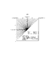
- FIG. 6 is a schematic diagram showing the types (mode numbers) of the intra prediction modes. As shown in FIG. 6, there are 67 types (0 to 66) of intra prediction modes, for example. For example, planar prediction (0), DC prediction (1), Angular prediction (2-66). In addition, LM mode (67-72) may be added for color difference.
- the syntax elements for deriving the intra prediction parameters include, for example, intra_luma_mpm_flag, intra_luma_mpm_idx, intra_luma_mpm_remainder and the like.
- intra_luma_mpm_flag is a flag indicating whether or not IntraPredModeY and MPM (Most Probable Mode) of the target block match.
- MPM is a prediction mode included in the MPM candidate list mpmCandList [].
- the MPM candidate list is a list that stores candidates that are presumed to have a high probability of being applied to the target block from the intra prediction mode of the adjacent block and the predetermined intra prediction mode.
- intra_luma_mpm_flag is 1, the IntraPredModeY of the target block is derived using the MPM candidate list and the index intra_luma_mpm_idx.
- IntraPredModeY mpmCandList [intra_luma_mpm_idx] (REM)
- intra_luma_mpm_flag 0
- the intra prediction mode is selected from the remaining modes RemIntraPredMode excluding the intra prediction modes included in the MPM candidate list from the entire intra prediction mode.
- the intra prediction mode that can be selected as RemIntraPredMode is called "non-MPM" or "REM”.
- RemIntraPredMode is derived using intra_luma_mpm_remainder.
- the moving image decoding device 31 includes an entropy decoding unit 301, a parameter decoding unit (predicted image decoding device) 302, a loop filter 305, a reference picture memory 306, a predicted parameter memory 307, a predicted image generator (predicted image generator) 308, and a reverse. It is composed of a quantization / inverse conversion unit 311 and an addition unit 312. In addition, there is also a configuration in which the loop filter 305 is not included in the moving image decoding device 31 in accordance with the moving image coding device 11 described later.
- the parameter decoding unit 302 further includes a header decoding unit 3020, a CT information decoding unit 3021, and a CU decoding unit 3022 (prediction mode decoding unit), and the CU decoding unit 3022 includes a TU decoding unit 3024. These may be generically called a decoding module.
- the header decoding unit 3020 decodes the parameter set information such as VPS, SPS, PPS, and the slice header (slice information) from the encoded data.
- the CT information decoding unit 3021 decodes the CT from the encoded data.
- the CU decoding unit 3022 decodes the CU from the encoded data.
- the TU decoding unit 3024 decodes the QP update information (quantization correction value) and the quantization prediction error (residual_coding) from the coded data when the TU includes a prediction error.
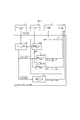
- FIG. 23 is a block diagram showing the relationship between the TU decoding unit 3024 and the inverse conversion unit 3112.
- the stIdx decoding unit 131 of the TU decoding unit 3024 decodes the value stIdx indicating whether or not the secondary conversion is used and the conversion basis from the encoded data, and outputs the value to the secondary conversion unit 31121.
- the mts_idx decoding unit 132 of the TU decoding unit 3024 decodes the value mts_idx indicating the MTS transformation matrix from the encoded data and outputs it to the core conversion unit 31123.
- the width and height of the CU are 4 or more
- the prediction mode is the intra mode
- the number of conversion coefficients in the CU numSigCoeff is a predetermined number THSt (for example).
- SINGLE_TREE is 2, otherwise 1) Decrypts stIdx. If stIdx is 0, the secondary transformation is not applied. If stIdx is 1, the transformation of one of the sets (pairs) of the secondary transformation matrix is shown. If stIdx is 2, the above The transformation of the other of the pairs is shown. Further, the secondary transformation matrix secTransMatrix may be selected not only according to the value of stIdx but also according to the intra prediction mode and the size of the transformation.
- the parameter decoding unit 302 includes an inter-prediction parameter decoding unit 303 and an intra-prediction parameter decoding unit 304 (not shown).
- the prediction image generation unit 308 includes an inter prediction image generation unit 309 and an intra prediction image generation unit 310.
- CTU and CU as the processing unit
- processing is not limited to this example, and processing may be performed in sub-CU units.
- CTU and CU may be read as blocks
- sub-CUs may be read as sub-blocks
- processing may be performed in units of blocks or sub-blocks.
- the entropy decoding unit 301 performs entropy decoding on the coded stream Te input from the outside, separates and decodes each code (syntax element).
- CABAC Context Adaptive Binary Arithmetic Coding
- the probability model of the picture using the same slice type and the same slice level quantization parameter is set from the probability models stored in the memory.
- This initial state is used for encoding and decoding processing.
- the separated codes include prediction information for generating a prediction image, prediction error for generating a difference image, and the like.
- the entropy decoding unit 301 outputs the separated codes to the parameter decoding unit 302.
- the separated code is, for example, the prediction mode predMode.
- the control of which code is decoded is performed based on the instruction of the parameter decoding unit 302.
- FIG. 8 is a flowchart illustrating a schematic operation of the moving image decoding device 31.
- the header decoding unit 3020 decodes the parameter set information such as VPS, SPS, and PPS from the encoded data.
- the header decoding unit 3020 decodes the slice header (slice information) from the encoded data.
- the moving image decoding device 31 derives the decoded image of each CTU by repeating the processes of S1300 to S5000 for each CTU included in the target picture.
- the CT information decoding unit 3021 decodes the CTU from the encoded data.
- the CT information decoding unit 3021 decodes the CT from the encoded data.
- the CU decoding unit 3022 executes S1510 and S1520 to decode the CU from the encoded data.
- the CU decoding unit 3022 decodes CU information, prediction information, TU division flag split_transform_flag, CU residual flags cbf_cb, cbf_cr, cbf_luma, etc. from the encoded data.
- the TU decoding unit 3024 decodes the QP update information (quantization correction value) and the quantization prediction error (residual_coding) from the coded data when the TU contains a prediction error.
- the QP update information is a difference value from the quantization parameter prediction value qPpred, which is the prediction value of the quantization parameter QP.
- the prediction image generation unit 308 generates a prediction image based on the prediction information for each block included in the target CU.
- Inverse quantization / inverse conversion unit 311 executes inverse quantization / inverse conversion processing for each TU included in the target CU.
- the addition unit 312 decodes the target CU by adding the prediction image supplied by the prediction image generation unit 308 and the prediction error supplied by the inverse quantization / inverse conversion unit 311. Generate an image.
- the loop filter 305 applies a loop filter such as a deblocking filter, SAO, or ALF to the decoded image to generate a decoded image.
- a loop filter such as a deblocking filter, SAO, or ALF
- the parameter decoding unit 302 includes an inter-prediction parameter decoding unit 303 and an intra-prediction parameter decoding unit 304 (not shown).
- the prediction image generation unit 308 includes an inter-prediction image generation unit 309 and an intra-prediction image generation unit 310 (not shown).
- the intra prediction parameter decoding unit 304 decodes the intra prediction parameter, for example, the intrapred mode, with reference to the prediction parameter stored in the prediction parameter memory 307, based on the code input from the entropy decoding unit 301.
- the intra prediction parameter decoding unit 304 outputs the decoded intra prediction parameter to the prediction image generation unit 308, and stores it in the prediction parameter memory 307.
- the intra prediction parameter decoding unit 304 may derive an intra prediction mode that differs depending on the brightness and the color difference.
- FIG. 9 is a schematic diagram showing the configuration of the intra-prediction parameter decoding unit 304 of the parameter decoding unit 302.
- the intra prediction parameter decoding unit 304 includes a parameter decoding control unit 3041, a luminance intra prediction parameter decoding unit 3042, and a color difference intra prediction parameter decoding unit 3043.
- the parameter decoding control unit 3041 instructs the entropy decoding unit 301 to decode the syntax element, and receives the syntax element from the entropy decoding unit 301.
- intra_luma_mpm_flag 1
- the parameter decoding control unit 3041 outputs intra_luma_mpm_idx to the MPM parameter decoding unit 30422 in the luminance intra prediction parameter decoding unit 3042.
- the parameter decoding control unit 3041 outputs the intra_luma_mpm_remainder to the non-MPM parameter decoding unit 30423 of the luminance intra prediction parameter decoding unit 3042.
- the parameter decoding control unit 3041 outputs the syntax element of the color difference intra prediction parameter to the color difference intra prediction parameter decoding unit 3043.
- the luminance intra prediction parameter decoding unit 3042 includes an MPM candidate list derivation unit 30421, an MPM parameter decoding unit 30422, and a non-MPM parameter decoding unit 30423 (decoding unit, derivation unit).
- the MPM parameter decoding unit 30422 derives IntraPredModeY with reference to the mpmCandList [] and intra_luma_mpm_idx derived by the MPM candidate list derivation unit 30421, and outputs it to the intra prediction image generation unit 310.
- the non-MPM parameter decoding unit 30423 derives RemIntraPredMode from mpmCandList [] and intra_luma_mpm_remainder, and outputs IntraPredModeY to the intra prediction image generation unit 310.
- the color difference intra prediction parameter decoding unit 3043 derives IntraPredModeC from the syntax element of the color difference intra prediction parameter and outputs it to the intra prediction image generation unit 310.
- the brightness intra-prediction parameter decoding unit 3042 may further decode the flag intra_subpartitions_mode_flag indicating whether or not to perform the intra-sub-division that divides the CU into smaller sub-blocks and performs the intra-prediction. If intra_subpartitions_mode_flag is other than 0, the intra_subpartitions_split_flag is further decoded.
- the intra-sub-division mode is derived by the following equation.
- IntraSubPartSplitType is 0 (ISP_NO_SPLIT)
- IntraSubPartSplitType is 1 (ISP_HOR_SPLIT: horizontal division)
- the CU is vertically divided into 2 to 4 sub-blocks, and intra-prediction, conversion coefficient decoding, and inverse quantization / inverse conversion are performed for each sub-block.
- IntraSubPartSplitType is 2 (ISP_VER_SPLIT: vertical division)
- the CU is divided horizontally into 2 to 4 sub-blocks, and intra-prediction, conversion coefficient decoding, and inverse quantization / inverse conversion are performed for each sub-block.
- the number of subblock divisions NumIntraSubPart is derived by the following formula.
- the loop filter 305 is a filter provided in the coding loop, which removes block distortion and ringing distortion to improve image quality.
- the loop filter 305 applies filters such as a deblocking filter, a sample adaptive offset (SAO), and an adaptive loop filter (ALF) to the decoded image of the CU generated by the addition unit 312.
- filters such as a deblocking filter, a sample adaptive offset (SAO), and an adaptive loop filter (ALF) to the decoded image of the CU generated by the addition unit 312.
- the reference picture memory 306 stores the decoded image of the CU generated by the addition unit 312 at a predetermined position for each target picture and the target CU.
- the prediction parameter memory 307 stores the prediction parameters at a predetermined position for each CTU or CU to be decoded. Specifically, the prediction parameter memory 307 stores the parameters decoded by the parameter decoding unit 302 and the pred mode and the like separated by the entropy decoding unit 301.
- PredMode, prediction parameters, etc. are input to the prediction image generation unit 308. Further, the prediction image generation unit 308 reads the reference picture from the reference picture memory 306. The prediction image generation unit 308 generates a prediction image of a block or a subblock by using the prediction parameter and the read reference picture (reference picture block) in the prediction mode indicated by predMode.
- the reference picture block is a set of pixels on the reference picture (usually called a block because it is rectangular), and is an area to be referred to for generating a predicted image.
- the intra prediction image generation unit 310 performs the intra prediction using the intra prediction parameters input from the intra prediction parameter decoding unit 304 and the reference pixels read from the reference picture memory 306.
- the intra prediction image generation unit 310 reads an adjacent block on the target picture within a predetermined range from the target block from the reference picture memory 306.
- the predetermined range is adjacent blocks on the left, upper left, upper, and upper right of the target block, and the area to be referred to differs depending on the intra prediction mode.
- the intra prediction image generation unit 310 generates a prediction image of the target block by referring to the read decoding pixel value and the prediction mode indicated by IntraPredMode.
- the intra prediction image generation unit 310 outputs the prediction image of the generated block to the addition unit 312.
- the decoded peripheral area adjacent (proximity) to the prediction target block is set as the reference area R.
- the predicted image is generated by extrapolating the pixels on the reference region R in a specific direction.
- the reference area R is an L-shaped area including the left and top of the prediction target block (or further, upper left, upper right, lower left) (for example, the pixels marked with diagonal circles in Example 1 of the reference area in FIG. It may be set as the area shown).
- the intra prediction image generation unit 310 includes a prediction target block setting unit 3101, an unfiltered reference image setting unit 3102 (first reference image setting unit), a filtered reference image setting unit 3103 (second reference image setting unit), and an intra. It includes a prediction unit 3104 and a prediction image correction unit 3105 (prediction image correction unit, filter switching unit, weight coefficient changing unit).
- the intra prediction unit 3104 Based on each reference pixel (unfiltered reference image) on the reference area R, the filtered reference image generated by applying the reference pixel filter (first filter), and the intra prediction mode, the intra prediction unit 3104 is a prediction target block. (Prediction image before correction) is generated and output to the prediction image correction unit 3105.
- the prediction image correction unit 3105 corrects the provisional prediction image according to the intra prediction mode, generates a prediction image (corrected prediction image), and outputs the prediction image.
- the prediction target block setting unit 3101 sets the target CU as the prediction target block, and outputs information (prediction target block information) regarding the prediction target block.
- the prediction target block information includes at least an index indicating the size, position, brightness or color difference of the prediction target block.
- the unfiltered reference image setting unit 3102 sets the adjacent peripheral area of the prediction target block as the reference area R based on the size and position of the prediction target block. Subsequently, each pixel value (unfiltered reference image, boundary pixel) in the reference area R is set with each decoded pixel value at the corresponding position on the reference picture memory 306.
- the line r [x] [-1] of the decoding pixels adjacent to the upper side of the prediction target block shown in Example 1 of the reference area of FIG. 10, and the row r [-1] [y] of the decoding pixels adjacent to the left side of the prediction target block. ] Is an unfiltered reference image.
- the filtered reference image setting unit 3103 applies a reference pixel filter (first filter) to the unfiltered reference image according to the intra prediction mode, and filters each position (x, y) on the reference area R. Derivation of the reference image s [x] [y]. Specifically, a low-pass filter is applied to the unfiltered reference image at the position (x, y) and its surroundings, and the filtered reference image (example 2 of the reference area in FIG. 10) is derived. It is not always necessary to apply the low-pass filter to all the intra-prediction modes, and the low-pass filter may be applied to some of the intra-prediction modes.
- a reference pixel filter first filter
- the filter applied to the unfiltered reference image on the reference area R is called a “reference pixel filter (first filter)", whereas in the prediction image correction unit 3105 described later.
- a filter that corrects a tentatively predicted image is called a “boundary filter (second filter)”.
- the intra prediction unit 3104 generates a tentative prediction image (provisional prediction pixel value, pre-correction prediction image) of the prediction target block based on the intra prediction mode, the unfiltered reference image, and the filtered reference pixel value, and the prediction image correction unit Output to 3105.
- the intra prediction unit 3104 includes a Planar prediction unit 31041, a DC prediction unit 31042, an Angular prediction unit 31043, and an LM prediction unit 31044 inside.
- the intra prediction unit 3104 selects a specific prediction unit according to the intra prediction mode, and inputs an unfiltered reference image and a filtered reference image.
- the relationship between the intra prediction mode and the corresponding prediction unit is as follows.
- Planar Prediction ⁇ ⁇ ⁇ Planar Prediction Department 31041 DC prediction ⁇ ⁇ ⁇ DC prediction unit 31042 ⁇ Angular Prediction ⁇ ⁇ ⁇ Angular Prediction Department 31043 ⁇ LM prediction ⁇ ⁇ ⁇ LM prediction unit 31044 (Planar forecast)
- the Planar prediction unit 31041 linearly adds a plurality of filtered reference images according to the distance between the prediction target pixel position and the reference pixel position to generate a tentative prediction image, and outputs the provisional prediction image to the prediction image correction unit 3105.
- the DC prediction unit 31042 derives a DC prediction value corresponding to the average value of the filtered reference images s [x] [y], and outputs a provisional prediction image q [x] [y] using the DC prediction value as a pixel value. To do.
- the Angular prediction unit 31043 generates a tentative prediction image q [x] [y] using the filtered reference images s [x] [y] in the prediction direction (reference direction) indicated by the intra prediction mode, and the prediction image correction unit. Output to 3105.
- the LM prediction unit 31044 predicts the pixel value of the color difference based on the pixel value of the luminance. Specifically, it is a method of generating a predicted image of a color difference image (Cb, Cr) using a linear model based on a decoded luminance image.
- CCLM Cross-Component Linear Model prediction
- LM prediction is a prediction method that uses a linear model for predicting the color difference from the luminance for one block.
- the prediction image correction unit 3105 corrects the tentative prediction image output from the intra prediction unit 3104 according to the intra prediction mode. Specifically, the prediction image correction unit 3105 weights and adds the unfiltered reference image and the provisional prediction image to each pixel of the provisional prediction image according to the distance between the reference region R and the target prediction pixel (weighted average). By doing so, the predicted image (corrected predicted image) Pred obtained by modifying the provisional predicted image is derived. In some intra-prediction modes, the prediction image correction unit 3105 may not correct the provisional prediction image, and the output of the intra-prediction unit 3104 may be used as the prediction image as it is.
- the inverse quantization / inverse conversion unit 311 inversely quantizes the quantization conversion coefficient qd [] [] input from the entropy decoding unit 301 to obtain the conversion coefficient d [] [].
- This quantization transform coefficient qd [] [] performs frequency conversion such as DCT (Discrete Cosine Transform) and DST (Discrete Sine Transform) on the prediction error in the coding process. It is a coefficient obtained by transforming.
- the inverse quantization / inverse conversion unit 311 performs inverse frequency conversion such as inverse DCT and inverse DST on the obtained conversion coefficient, and calculates a prediction error.
- the inverse quantization / inverse conversion unit 311 outputs the prediction error to the addition unit 312.
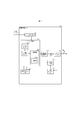
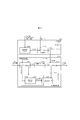
- FIG. 12 is a functional block diagram showing a configuration example of the inverse quantization / inverse conversion unit 311.
- the quantization / inverse conversion unit 311 includes an inverse quantization unit 3111 and a conversion unit 3112.
- the inverse quantization unit 3111 dequantizes the quantization conversion coefficient qd [] [] decoded by the TU decoding unit 3024, and derives the conversion coefficient d [] [].
- the inverse quantization unit 3111 outputs the derived conversion coefficient d [] [] to the conversion unit 3112.
- the conversion unit 3112 reversely converts the received conversion coefficient d [] [] for each conversion unit TU, and restores the prediction error r [] [].
- the conversion unit 3112 outputs the restored prediction error r [] [] to the addition unit 312.
- the process of converting the difference image into the conversion coefficient in the image coding apparatus is called forward conversion
- the process of converting the conversion coefficient in the image decoding apparatus into the difference image is called conversion.
- the term "inverse conversion” may be used instead of "conversion” for the conversion process in the conversion unit 3112.
- the conversion unit 3112 includes a secondary conversion unit (second conversion unit) 31121 and a core conversion unit (first conversion unit) 31123.
- the TU decoding unit 3024 further divides the CU into a plurality of subblocks, decodes the conversion coefficient of only one of the plurality of subblocks, and decodes the subblock conversion flag cu_sbt_flag that performs inverse quantization and inverse conversion. You may. When cu_sbt_flag is 1, the flag cu_sbt_quad_flag indicating whether to divide into four subblocks may be further decoded. When cu_sbt_quad_flag is 0, the number of subblocks is 2. When cu_sbt_quad_flag is 1, the number of subblocks is 4. It also decodes the cu_sbt_horizontal_flag, which indicates whether to split horizontally or vertically. It also decodes the cu_sbt_pos_flag, which indicates which subblock contains the conversion factor.
- the scaling unit 31112 scales the conversion coefficient decoded by the TU decoding unit using a weight in coefficient units.
- the quantization matrix m [x] [y] and the scaling factor ls [x] [y] are derived by the following equations.
- the scaling unit 31112 derives dnc [] [] from the product of the scaling factor ls [] [] and the decoded conversion coefficient TransCoeffLevel, and performs inverse quantization.
- dnc [x] [y] (TransCoeffLevel [xTbY] [yTbY] [cIdx] [x] [y] * ls [x] [y] * rectNorm + bdOffset) >> bdShift
- the scaling unit 31112 clips the inverse quantized conversion coefficient to derive d [x] [y].
- d [x] [y] Clip3 (CoeffMin, CoeffMax, dnc [x] [y]) d [x] [y] is transmitted to the core conversion unit 31123 or the secondary conversion unit 31121.
- the secondary conversion unit (second conversion unit) 31121 applies the secondary conversion to the conversion coefficient d [] [] after the inverse quantization and before the core conversion.
- the secondary conversion unit 31121 applies a transformation using a transformation matrix to a part or all of the conversion coefficients d [] [] received from the inverse quantization unit 3111, thereby performing a correction conversion coefficient (second conversion). (Conversion coefficient after conversion by part) d [] [] is restored.
- the secondary conversion unit 31121 applies the secondary conversion to the conversion coefficient d [] [] in a predetermined unit for each conversion unit TU.
- the secondary transformation is applied only in the intra CU, and the transformation basis is determined with reference to the intrapred mode. The selection of the conversion basis will be described later.
- the secondary conversion unit 31121 outputs the restored correction conversion coefficient d [] [] to the core conversion unit 31123.
- the core conversion unit 31123 acquires the conversion coefficient d [] [] or the correction conversion coefficient d [] [] restored by the secondary conversion unit 31121, performs conversion, and derives the prediction error r [] [].
- the core conversion unit 31123 outputs the prediction error r [] [] to the addition unit 312.
- FIG. 19 shows a forward conversion unit 1032 included in the conversion / quantization unit 103 of the moving image coding apparatus 11 and an inverse conversion unit 152 included in the inverse conversion / inverse quantization unit 105.
- the secondary conversion is applied to the conversion coefficient of a part or all of the decoded TU, and the core conversion (DCT2, DST7, etc.) is applied to the conversion coefficient after the secondary conversion.
- FIG. 13 is a diagram illustrating a secondary conversion.
- the conversion coefficient d [] [] in the 4x4 region is stored in the nonZeroSize one-dimensional array u [] in the S2 processing, and the one-dimensional array u [] to the one-dimensional array in the S3 processing.
- the process of converting to v [] and finally storing it in d [] [] in the process of S4 is shown.
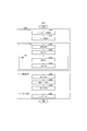
- FIG. 24 is a flowchart showing the processing of the secondary conversion.
- the secondary conversion unit 31121 determines the size of the secondary conversion (4x4 or 8x8), the number of conversion coefficients of the output (nStOutSize), and the conversion coefficient of the application (input conversion coefficient) according to the size of the TU (width nTbW, height nTbH). ) Number nonZeroSize and the number of subblocks (numStX, numStY) to which the secondary transformation is applied are derived.
- the secondary conversion unit 31121 When the TU is larger than the specified size, the secondary conversion unit 31121 outputs 48 conversion coefficients by the secondary conversion of RST8x8. Otherwise, RST4x4 secondary conversion outputs 16 conversion coefficients.
- the TU is 4x4
- 16 conversion coefficients are derived from the conversion coefficient of 8 using RST4x4
- the conversion coefficient of 48 is derived from the conversion coefficient of 8 using RST8x8. In other cases, 16 or 48 conversion coefficients are output from 16 conversion coefficients depending on the size of the TU.
- xC and yC are positions on the TU, and are derived from the array DiagScanOrder indicating the scan order and the position x of the conversion coefficient in the subblock.
- the secondary conversion unit 31121 converts u [] (vector F') having a length of nonZeroSize using a conversion basis (matrix) T of the first kind, and outputs a one-dimensional array having a length of nStOutSize. Derivation of v'[] (vector V').
- This conversion can be expressed by the following formula in matrix operation.
- V' T ⁇ F'
- the conversion basis when the conversion size is 4x4 (RST4x4) is called the first type conversion basis T1.
- the conversion basis is called the second type conversion basis T2.
- T1 is a 16x16 (16 rows 16 columns) matrix
- the transformation is 16x1 (16 rows 1 column) vector
- T2 is a 48x16 (48 rows 16 columns) matrix
- the transformation is the product of the 48x16 matrix T and the 16x1 vector F', which is the 48x1 (48 rows 1 column, length 48) vector V', that is. , Derivation of a one-dimensional array v'[] of length 48.
- the secondary conversion unit 31121 includes a set number (stTrSetId) of the secondary conversion derived from the intrapred mode IntraPredMode, stIdx indicating the conversion basis of the secondary conversion decoded from the encoded data, and a secondary conversion size nStSize. Derivation of the corresponding transformation matrix secTranMatrix [] [] (transformation basis T1 or T2) from (nTrS). Further, the secondary conversion unit 31121 performs a multiply-accumulate operation between the transformation matrix and the one-dimensional array u [], as shown in the following equation.
- stTrSetId set number of the secondary conversion derived from the intrapred mode IntraPredMode
- stIdx indicating the conversion basis of the secondary conversion decoded from the encoded data
- nStSize secondary conversion size
- v'[i] Clip3 (CoeffMin, CoeffMax, ⁇ secTransMatrix [j] [i] * u [j])
- i processes 0..nStSize-1.
- CoeffMin and CoeffMax indicate the range of conversion coefficient values.
- the secondary conversion unit 31121 repositions the coefficient v'[] of the converted one-dimensional array at a predetermined position in the TU.
- the secondary conversion unit 31121 arranges a coefficient v'[] having a length of nStOutSize obtained by the above process S3 in the upper left area of the conversion coefficient array d [] [].
- the conversion used in the core conversion is a separation type conversion consisting of a vertical conversion and a horizontal conversion. Further, the transformation that separates the two-dimensional signal in the horizontal direction and the vertical direction may be defined as the first transformation. Further, in the image decoding apparatus, the conversion applied after the second conversion (secondary conversion) may be defined as the first conversion.
- the transformation basis (transformation matrix) of the core transformation is DCT2, DST7, DCT8. In the core conversion, the conversion basis is switched independently for the vertical conversion and the horizontal conversion. The selectable conversion is not limited to the above, and another conversion (conversion basis) can be used.
- DCT2, DST7, DCT8, DST1 and DCT5 may be represented as DCT-II, DST-VII, DCT-VIII, DST-I and DCT-V, respectively. There may be conversion skip as a mode for explicitly skipping core conversion.
- MTS There are explicit MTS and implicit MTS for core conversion.
- decode mts_idx from the encoded data and switch the transformation matrix.
- mts_idx is derived according to the intra prediction mode and block size.
- decoding mts_idx in CU units or TU units is described, but the decoding (switching) unit is not limited to this.
- Mts_idx is a switching index for selecting the conversion basis of core conversion.
- mts_idx has one of the values 0, 1, 2, 3, and 4, and derives the horizontal conversion type trTypeHor and the vertical conversion type trTypeVer.
- the core conversion described above will be specifically described with reference to FIG.
- the core conversion unit 1521 of FIG. 18 is an example of the core conversion unit 31123 of FIG. 12 and the core conversion unit 1521 of FIG.
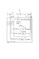
- the core conversion unit 1521 in FIG. 18 uses the MTS setting unit 15211 that sets the type of conversion used from a plurality of conversion bases and the (corrected) conversion coefficient d [] [] using the derived conversion to predict the residual r [ ] [] Is composed of a coefficient conversion processing unit 15212 for calculating and a matrix conversion processing unit 15213 for performing actual conversion. If no secondary conversion is performed, the modified conversion factor is equal to the conversion factor. When the secondary conversion is performed, the modified conversion factor takes a value different from the conversion factor.
- the MTS setting unit 15211 is composed of an MTS setting unit 152111 that determines the method for deriving the index mts_ids of the conversion to be used, and an implicit MTS setting unit 152112 that implicitly derives mts_idx.
- the MTS setting unit 152111 selects whether to perform explicit MTS, implicit MTS, or not MTS.
- the MTS setting unit 152111 uses the explicit MTS when the explicit MTS is valid (when the sps_explicit_mts_flag is 1), and uses the mts_idx decoded from the encoded data in the subsequent processing.
- the explicitMtsEnabled flag for whether explicit MTS is enabled may be set individually for intramode and intermode.
- PredMode is intermode (other than MODE_INTRA) and sps_explicit_mts_inter_enabled_flag is 1, or if PredMode is intramode (MODE_INTRA) and sps_explicit_mts_intra_enabled_flag is 1, it is determined that explicit MTS is valid and the encoded data.
- PredMode is intramode (MODE_INTRA) and sps_explicit_mts_intra_enabled_flag is 1, it is determined that explicit MTS is valid and the encoded data.
- You may decrypt mts_idx from.
- the TU decoding unit 3024 decodes mts_idx from the encoded data when the explicit MTS is valid (sps_explicit_mts_flag is 1).
- conversion may be performed by combining DST1 and DCT4, and pre-processing and post-processing and DCT2.
- the effective range of MTS can be limited, which has the effect of simplifying coding.
- restriction example 2 since the secondary conversion is not performed in the case of DCT8 whose effect overlaps with the secondary conversion, the overhead due to mts_idx is reduced and the coding efficiency is improved.
- An image decoding device including a conversion unit that converts a conversion coefficient for each TU, and the conversion unit applies a conversion using a transformation matrix to the input conversion coefficient when the secondary conversion is effective.
- the second range includes the first range.
- the TU decoding unit decodes mts_idx.
- the implicit MTS setting unit 152112 performs the following processing in the case of an implicit MTS.
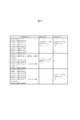
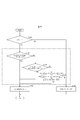
- the implicit MTS setting unit 152112 is set to 1 (DST7) as tyTypeHor, tyTypeVer according to cu_sbt_horizontal_flag and cu_sbt_pos_flag as shown in FIG. ) Or 2 (DCT8).
- the implicit MTS setting unit 152112 has either 0 (DCT2) or 1 (DST7) as tyTypeHor or tyTypeVer depending on the TU size (width nTbW, height nTbH).
- the horizontal conversion type trTypeHor is set to 1 (DCT1) when the width nTbW is within a predetermined range (S1301) (S1302), and 0 (DCT2) in other cases. ) (S1303).
- the vertical conversion type trTypeVer 1 (DCT1) is set when the height nTbH is within a predetermined range (S1304) (S1305), and 0 (DCT2) is set otherwise (S1306).
- the predetermined range is not limited to the above. For example, it may be as follows.
- the default implicit MTS above is the most common implicit MTS mode.
- SM000 may be performed before SM001 described above.
- FIG. 21 is a diagram illustrating the operation of the implicit MTS setting unit 152112.
- SM003' may be performed instead of the above SM003.
- the implicit MTS setting unit 152112 sets 0 (DCT2) or 1 (DCT2) or 1 (tyTypeHor, tyTypeVer) depending on the secondary conversion and TU size (width nTbW, height nTbH).
- the MTS setting unit 15211 derives the index trType of the conversion set to be used by the following formula and outputs it to the coefficient conversion processing unit 15212.
- the coefficient conversion processing unit 15212 outputs the input trType to the transformation matrix derivation unit 152131.
- the MTS setting unit 152111 derives a value indicating the MTS to be used by the following formula.
- the coefficient conversion processing unit 15212 is composed of a vertical conversion unit 152121 that performs vertical conversion on the correction conversion coefficient d [] [] and a horizontal conversion unit 152123 that performs horizontal conversion.
- the vertical conversion unit 152121 (coefficient conversion processing unit 15212) performs the following processing.
- nTbS is the height of TU nTbH.
- transMatrix ⁇ 29, 55, 74, 84 ⁇ ⁇ 74, 74, 0, -74 ⁇ ⁇ 84, -29, -74 , 55 ⁇ ⁇ 55, -84, 74, -29 ⁇ .
- the intermediate clip unit 152122 derives the intermediate value g [] [] by clipping the intermediate value e [] [] and sends it to the horizontal conversion unit 152123.
- g [x] [y] Clip3 (coeffMin, coeffMax, (e [x] [y] + 64) >> 7)
- the above equations 64 and 7 are numerical values determined by the bit depth of the conversion basis, and the above equation assumes that the conversion basis is 7 bits. Also, coeffMin and coeffMax are the minimum and maximum values of clipping.
- the horizontal conversion unit 152123 (coefficient conversion processing unit 15212) performs the following processing.
- nTbS is the width of TU, nTbW.
- the horizontal conversion unit 152123 converts the intermediate value g [x] [y] into the predicted residual r [x] [y] by the horizontal one-dimensional conversion.
- the predicted residual r [] [] is sent from the horizontal converter 152123 to the adder 312.
- the vertical conversion unit 152121 and the horizontal conversion unit 152123 perform conversion by the matrix conversion processing unit 15213.
- the matrix conversion processing unit 15213 is composed of a conversion matrix derivation unit 152131 and a conversion processing unit 152132.
- the transformation matrix derivation unit 152131 derives the transformation matrix transMatrix [] [] according to the length of the TU (nTbW, nTbH) and the index tyType (trTypeHor, trTypeVer) of the core transformation.
- the matrix conversion processing unit 15213 converts the one-dimensional array xx [j] input using the derived transformation matrix transMatrix [] [] into the one-dimensional array yy [i], and performs vertical conversion and horizontal conversion.
- the conversion coefficient d [x] [j] of the x column is input as the one-dimensional conversion coefficient xx [j] for conversion.
- the intermediate coefficient g [j] [y] in the y row is input as xx [j] for conversion.
- the TU decoding unit 3024 may limit the range of the value of stIdx to be decoded depending on whether the value of mts_idx is valid or not.
- the variable stIdx indicating the type of the secondary conversion is decoded only when the conversion in a predetermined range is performed by the MTS, so that the effective range of the secondary conversion is limited, so that the coding is simplified. Play. Further, for example, in the limitation example 2, since the secondary conversion is not performed in the case of DCT8 whose effect overlaps with the secondary conversion, the overhead due to stIdx is reduced and the coding efficiency is improved.
- the addition unit 312 adds the prediction image of the block input from the prediction image generation unit 308 and the prediction error input from the inverse quantization / inverse conversion unit 311 for each pixel to generate a decoded image of the block.
- the addition unit 312 stores the decoded image of the block in the reference picture memory 306, and outputs the decoded image to the loop filter 305.
- FIG. 16 is a block diagram showing the configuration of the moving image coding device 11 according to the present embodiment.
- the moving image coding device 11 includes a prediction image generation unit 101, a subtraction unit 102, a conversion / quantization unit 103, an inverse quantization / inverse conversion unit 105, an addition unit 106, a loop filter 107, and a prediction parameter memory (prediction parameter storage unit).
- Frame memory 108, reference picture memory (reference image storage unit, frame memory) 109, coding parameter determination unit 110, parameter coding unit 111, and entropy coding unit 104.
- the predicted image generation unit 101 generates a predicted image for each CU, which is a region in which each picture of the image T is divided.
- the prediction image generation unit 101 has the same operation as the prediction image generation unit 308 described above, and the description thereof will be omitted.
- the subtraction unit 102 subtracts the pixel value of the predicted image of the block input from the prediction image generation unit 101 from the pixel value of the image T to generate a prediction error.
- the subtraction unit 102 outputs the prediction error to the conversion / quantization unit 103.
- the conversion / quantization unit 103 calculates the conversion coefficient by frequency conversion for the prediction error input from the subtraction unit 102, and derives the quantization conversion coefficient by quantization.
- the conversion / quantization unit 103 outputs the quantization conversion coefficient to the entropy coding unit 104 and the inverse quantization / inverse conversion unit 105.
- the conversion / quantization unit 103 includes a forward core conversion 10321 (first conversion unit) and a forward secondary conversion unit 10322 (second conversion unit).
- the processing S1-S4 of the secondary conversion applied to the moving image decoding device 31 is almost the same except that the processing S1, S4, S3, and S2 are applied in the reverse order. I do.
- the forward secondary conversion unit 10322 performs the same processing as the secondary conversion unit 31121 except that the input and output of the secondary conversion have lengths nStOutSize and nonZeroSize, respectively.
- the forward / secondary conversion unit 10322 derives a one-dimensional array v [] of nStOutSize (or nStSize * nStSize) from the conversion coefficient d [] [] at a predetermined position in the TU.
- the forward secondary conversion unit 10322 performs the following conversion from the one-dimensional array v [] (vector V) of nStOutSize and the transformation matrix T [] [], and the one-dimensional array u [] (vector F) of nonZeroSize To get.
- trans (T) is the transpose matrix of T.
- the secondary conversion unit may derive a one-dimensional array u [] (vector F) by the following equation.
- Tinv is the inverse matrix of T.
- T is composed of a first-class conversion basis T1 and a second-class conversion basis T2.
- the secondary conversion unit may set trans (T) of T to Tinv by using an orthogonal matrix with respect to T.
- the secondary conversion unit uses a matrix that is a constant multiple of the inverse matrix as Tinv, but the inverse matrix may be used as it is for the transposed matrix.
- the forward / secondary conversion unit 10322 rearranges the nonZeroSize one-dimensional array u [] into a two-dimensional array to derive the conversion coefficient d [] [].
- xC (xSbIdx ⁇ log2StSize) + DiagScanOrder [log2StSize] [log2StSize] [x] [0]
- the inverse quantization / inverse conversion unit 105 is the same as the inverse quantization / inverse conversion unit 311 (FIG. 15) in the moving image decoding device 31, and the description thereof will be omitted.
- the calculated prediction error is output to the addition unit 106.
- the quantization conversion coefficient is input from the conversion / quantization unit 103 to the entropy coding unit 104, and the coding parameter is input from the parameter coding unit 111.
- the coding parameter is, for example, predMode.
- the entropy coding unit 104 entropy-encodes the division information, prediction parameters, quantization conversion coefficient, etc., generates a coded stream Te, and outputs the coded stream Te.
- the parameter coding unit 111 includes a header coding unit 1110 (not shown), a CT information coding unit 1111, a CU coding unit 1112 (prediction mode coding unit), an inter prediction parameter coding unit 112, and an intra prediction parameter coding unit. It has 113.
- the CU coding unit 1112 further includes a TU coding unit 1114.
- the parameter coding unit 111 performs parameter coding processing such as header information, division information, prediction information, and quantization conversion coefficient.
- the CT information coding unit 1111 encodes QT, MT (BT, TT) division information, etc. from the coded data.
- the CU coding unit 1112 encodes CU information, prediction information, TU division flag, CU residual flag, etc.
- the TU coding unit 1114 encodes the QP update information (quantization correction value) and the quantization prediction error (residual_coding) when the TU contains a prediction error.
- the CT information coding unit 1111 and the CU coding unit 1112 supply syntax elements such as inter prediction parameters, intra prediction parameters (intra_luma_mpm_flag, intra_luma_mpm_idx, intra_luma_mpm_remainder), and quantization conversion coefficients to the entropy coding unit 104.
- the intra prediction parameter coding unit 113 derives a format for coding (for example, intra_luma_mpm_idx, intra_luma_mpm_remainder, etc.) from the IntraPredMode input from the coding parameter determination unit 110.
- the intra prediction parameter coding unit 113 includes a configuration that is partially the same as the configuration in which the intra prediction parameter decoding unit 304 derives the intra prediction parameter.
- FIG. 17 is a schematic diagram showing the configuration of the intra-prediction parameter coding unit 113 of the parameter coding unit 111.
- the intra prediction parameter coding unit 113 includes a parameter coding control unit 1131, a luminance intra prediction parameter derivation unit 1132, and a color difference intra prediction parameter derivation unit 1133.
- IntraPredModeY and IntraPredModeC are input from the coding parameter determination unit 110 to the parameter coding control unit 1131.
- the parameter coding control unit 1131 determines the intra_luma_mpm_flag by referring to the mpmCandList [] of the MPM candidate list derivation unit 30421. Then, intra_luma_mpm_flag and IntraPredModeY are output to the luminance intra prediction parameter derivation unit 1132.
- IntraPredModeC is output to the color difference intra prediction parameter derivation unit 1133.
- the luminance intra prediction parameter derivation unit 1132 includes an MPM candidate list derivation unit 30421 (candidate list derivation unit), an MPM parameter derivation unit 11322, and a non-MPM parameter derivation unit 11323 (encoding unit, derivation unit). To.
- the MPM candidate list derivation unit 30421 derives mpmCandList [] by referring to the intra prediction mode of the adjacent block stored in the prediction parameter memory 108.
- the MPM parameter derivation unit 11322 derives intra_luma_mpm_idx from IntraPredModeY and mpmCandList [] when intra_luma_mpm_flag is 1, and outputs it to the entropy coding unit 104.
- the non-MPM parameter derivation unit 11323 derives RemIntraPredMode from IntraPredModeY and mpmCandList [] when intra_luma_mpm_flag is 0, and outputs intra_luma_mpm_remainder to the entropy encoding unit 104.
- the color difference intra prediction parameter derivation unit 1133 derives intra_chroma_pred_mode from IntraPredModeY and IntraPredModeC and outputs it.
- the addition unit 106 adds the pixel value of the prediction image of the block input from the prediction image generation unit 101 and the prediction error input from the inverse quantization / inverse conversion unit 105 for each pixel to generate a decoded image.
- the addition unit 106 stores the generated decoded image in the reference picture memory 109.
- the loop filter 107 applies a deblocking filter, SAO, and ALF to the decoded image generated by the addition unit 106.
- the loop filter 107 does not necessarily have to include the above three types of filters, and may have, for example, a configuration of only a deblocking filter.
- the prediction parameter memory 108 stores the prediction parameters generated by the coding parameter determination unit 110 at predetermined positions for each target picture and CU.
- the reference picture memory 109 stores the decoded image generated by the loop filter 107 at a predetermined position for each target picture and CU.
- the coding parameter determination unit 110 selects one set from a plurality of sets of coding parameters.
- the coding parameter is the above-mentioned QT, BT or TT division information, prediction parameter, or a parameter to be coded generated in connection with these.
- the prediction image generation unit 101 generates a prediction image using these coding parameters.
- the coding parameter determination unit 110 calculates the RD cost value indicating the magnitude of the amount of information and the coding error for each of the plurality of sets.
- the coding parameter determination unit 110 selects the set of coding parameters that minimizes the calculated cost value.
- the entropy coding unit 104 outputs the selected set of coding parameters as the coding stream Te.
- the coding parameter determination unit 110 stores the determined coding parameter in the prediction parameter memory 108.
- a part of the moving image coding device 11 and the moving image decoding device 31 in the above-described embodiment for example, the entropy decoding unit 301, the parameter decoding unit 302, the loop filter 305, the predicted image generation unit 308, and the inverse quantization / reverse.
- the parameter coding unit 111 may be realized by a computer.
- the program for realizing this control function may be recorded on a computer-readable recording medium, and the program recorded on the recording medium may be read by the computer system and executed.
- the "computer system” referred to here is a computer system built in any of the moving image coding device 11 and the moving image decoding device 31, and includes hardware such as an OS and peripheral devices.
- the "computer-readable recording medium” refers to a portable medium such as a flexible disk, a magneto-optical disk, a ROM, or a CD-ROM, or a storage device such as a hard disk built in a computer system.
- a "computer-readable recording medium” is a medium that dynamically holds a program for a short period of time, such as a communication line when a program is transmitted via a network such as the Internet or a communication line such as a telephone line.
- a program may be held for a certain period of time, such as a volatile memory inside a computer system serving as a server or a client.
- the above-mentioned program may be a program for realizing a part of the above-mentioned functions, and may be a program for realizing the above-mentioned functions in combination with a program already recorded in the computer system.
- a part or all of the moving image coding device 11 and the moving image decoding device 31 in the above-described embodiment may be realized as an integrated circuit such as an LSI (Large Scale Integration).
- LSI Large Scale Integration
- Each functional block of the moving image coding device 11 and the moving image decoding device 31 may be made into a processor individually, or a part or all of them may be integrated into a processor.
- the method of making an integrated circuit is not limited to LSI, and may be realized by a dedicated circuit or a general-purpose processor. Further, when an integrated circuit technology that replaces an LSI appears due to advances in semiconductor technology, an integrated circuit based on this technology may be used.
- the moving image coding device 11 and the moving image decoding device 31 described above can be mounted on and used in various devices for transmitting, receiving, recording, and reproducing moving images.
- the moving image may be a natural moving image captured by a camera or the like, or an artificial moving image (including CG and GUI) generated by a computer or the like.
- moving image coding device 11 and moving image decoding device 31 can be used for transmitting and receiving moving images.
- FIG. 2 shows a block diagram showing the configuration of the transmission device PROD_A equipped with the moving image coding device 11.
- the transmitter PROD_A has a coding unit PROD_A1 that obtains encoded data by encoding a moving image, and a modulation signal by modulating a carrier wave with the coded data obtained by the coding unit PROD_A1. It includes a modulation unit PROD_A2 to obtain and a transmission unit PROD_A3 to transmit the modulation signal obtained by the modulation unit PROD_A2.
- the moving image coding device 11 described above is used as the coding unit PROD_A1.
- the transmitter PROD_A has a camera PROD_A4 for capturing a moving image, a recording medium PROD_A5 for recording a moving image, an input terminal PROD_A6 for inputting a moving image from the outside, and a moving image as a source of the moving image to be input to the coding unit PROD_A1.
- An image processing unit A7 for generating or processing an image may be further provided. In the figure, the configuration in which the transmitter PROD_A is provided with all of these is illustrated, but some of them may be omitted.
- the recording medium PROD_A5 may be a recording of an unencoded moving image, or a moving image encoded by a recording coding method different from the transmission coding method. It may be a thing. In the latter case, a decoding unit (not shown) that decodes the coded data read from the recording medium PROD_A5 according to the coding method for recording may be interposed between the recording medium PROD_A5 and the coding unit PROD_A1.
- FIG. 2 shows a block diagram showing the configuration of the receiving device PROD_B equipped with the moving image decoding device 31.
- the receiving device PROD_B is obtained by a receiving unit PROD_B1 that receives a modulated signal, a demodulating unit PROD_B2 that obtains coded data by demodulating the modulated signal received by the receiving unit PROD_B1, and a demodulating unit PROD_B2. It includes a decoding unit PROD_B3 that obtains a moving image by decoding the coded data.
- the moving image decoding device 31 described above is used as the decoding unit PROD_B3.
- the receiving device PROD_B is a display PROD_B4 for displaying the moving image, a recording medium PROD_B5 for recording the moving image, and an output terminal for outputting the moving image to the outside as a supply destination of the moving image output by the decoding unit PROD_B3. It may also have PROD_B6. In the figure, the configuration in which the receiving device PROD_B is provided with all of these is illustrated, but some of them may be omitted.
- the recording medium PROD_B5 may be used for recording an unencoded moving image, or may be encoded by a recording encoding method different from the transmission coding method. You may. In the latter case, a coding unit (not shown) that encodes the moving image acquired from the decoding unit PROD_B3 according to the recording coding method may be interposed between the decoding unit PROD_B3 and the recording medium PROD_B5.
- the transmission medium for transmitting the modulated signal may be wireless or wired.
- the transmission mode for transmitting the modulated signal may be broadcasting (here, a transmission mode in which the destination is not specified in advance) or communication (here, transmission in which the destination is specified in advance). Refers to an aspect). That is, the transmission of the modulated signal may be realized by any of wireless broadcasting, wired broadcasting, wireless communication, and wired communication.
- a broadcasting station (broadcasting equipment, etc.) / receiving station (television receiver, etc.) of terrestrial digital broadcasting is an example of a transmitting device PROD_A / receiving device PROD_B that transmits and receives modulated signals by radio broadcasting.
- a broadcasting station (broadcasting equipment, etc.) / receiving station (television receiver, etc.) of cable television broadcasting is an example of a transmitting device PROD_A / receiving device PROD_B that transmits and receives modulated signals by wired broadcasting.
- servers workstations, etc.
- clients television receivers, personal computers, smartphones, etc.
- VOD Video On Demand
- video sharing services using the Internet are transmitters that send and receive modulated signals via communication.
- PROD_A / receiver PROD_B usually, in LAN, either wireless or wired is used as a transmission medium, and in WAN, wired is used as a transmission medium.
- personal computers include desktop PCs, laptop PCs, and tablet PCs. Smartphones also include multifunctional mobile phone terminals.
- the client of the video sharing service has a function of decoding the encoded data downloaded from the server and displaying it on the display, as well as a function of encoding the moving image captured by the camera and uploading it to the server. That is, the client of the video sharing service functions as both the transmitting device PROD_A and the receiving device PROD_B.
- moving image coding device 11 and moving image decoding device 31 can be used for recording and reproducing moving images.
- FIG. 3 shows a block diagram showing the configuration of the recording device PROD_C equipped with the above-mentioned moving image coding device 11.
- the recording device PROD_C has a coding unit PROD_C1 that obtains coded data by encoding a moving image and a writing unit PROD_C2 that writes the coded data obtained by the coding unit PROD_C1 to the recording medium PROD_M. And have.
- the moving image coding device 11 described above is used as the coding unit PROD_C1.
- the recording medium PROD_M may be of a type built in the recording device PROD_C, such as (1) HDD (Hard Disk Drive) or SSD (Solid State Drive), or (2) SD memory. It may be of a type that is connected to the recording device PROD_C, such as a card or USB (Universal Serial Bus) flash memory, or (3) DVD (Digital Versatile Disc: registered trademark) or BD (Blu-ray). It may be loaded in a drive device (not shown) built in the recording device PROD_C, such as Disc (registered trademark).
- the recording device PROD_C has a camera PROD_C3 that captures a moving image, an input terminal PROD_C4 for inputting a moving image from the outside, and a reception for receiving the moving image as a source of the moving image to be input to the coding unit PROD_C1.
- a unit PROD_C5 and an image processing unit PROD_C6 for generating or processing an image may be further provided. In the figure, the configuration in which the recording device PROD_C is provided with all of these is illustrated, but some of them may be omitted.
- the receiving unit PROD_C5 may receive an unencoded moving image, or receives coded data encoded by a transmission coding method different from the recording coding method. It may be something to do. In the latter case, it is preferable to interpose a transmission decoding unit (not shown) between the receiving unit PROD_C5 and the coding unit PROD_C1 to decode the coded data encoded by the transmission coding method.
- Examples of such a recording device PROD_C include a DVD recorder, a BD recorder, an HDD (Hard Disk Drive) recorder, and the like (in this case, the input terminal PROD_C4 or the receiving unit PROD_C5 is the main source of moving images). ..
- a camcorder in this case, the camera PROD_C3 is the main source of moving images
- a personal computer in this case, the receiving unit PROD_C5 or the image processing unit C6 is the main source of moving images
- a smartphone this In this case, the camera PROD_C3 or the receiving unit PROD_C5 is the main source of moving images
- the recording device PROD_C is also examples of such a recording device PROD_C.
- FIG. 3 shows a block diagram showing the configuration of the playback device PROD_D equipped with the above-mentioned moving image decoding device 31.
- the playback device PROD_D includes a reading unit PROD_D1 that reads the coded data written in the recording medium PROD_M, and a decoding unit PROD_D2 that obtains a moving image by decoding the coded data read by the reading unit PROD_D1. , Is equipped.
- the moving image decoding device 31 described above is used as the decoding unit PROD_D2.
- the recording medium PROD_M may be of a type built in the playback device PROD_D, such as (1) HDD or SSD, or (2) such as an SD memory card or USB flash memory. It may be of a type connected to the playback device PROD_D, or may be loaded into a drive device (not shown) built in the playback device PROD_D, such as (3) DVD or BD. Good.
- the playback device PROD_D has a display PROD_D3 for displaying the moving image, an output terminal PROD_D4 for outputting the moving image to the outside, and a transmitting unit for transmitting the moving image as a supply destination of the moving image output by the decoding unit PROD_D2. It may also have PROD_D5. In the figure, the configuration in which the playback device PROD_D is provided with all of these is illustrated, but some of them may be omitted.
- the transmission unit PROD_D5 may transmit an unencoded moving image, or transmits coded data encoded by a transmission coding method different from the recording coding method. It may be something to do. In the latter case, it is preferable to interpose a coding unit (not shown) that encodes the moving image by a coding method for transmission between the decoding unit PROD_D2 and the transmitting unit PROD_D5.
- Examples of such a playback device PROD_D include a DVD player, a BD player, an HDD player, and the like (in this case, the output terminal PROD_D4 to which a television receiver or the like is connected is the main supply destination of moving images). ..
- a television receiver in this case, display PROD_D3 is the main supply destination of moving images
- digital signage also called electronic signage or electronic bulletin board, etc.
- display PROD_D3 or transmitter PROD_D5 is the main supply destination of moving images.
- desktop PC in this case, output terminal PROD_D4 or transmitter PROD_D5 is the main supply destination of moving images
- laptop or tablet PC in this case, display PROD_D3 or transmitter PROD_D5 is video
- An example of such a playback device PROD_D is a smartphone (in this case, the display PROD_D3 or the transmitter PROD_D5 is the main supply destination of the moving image) and the like (which is the main supply destination of the image).
- each block of the moving image decoding device 31 and the moving image coding device 11 described above may be realized in hardware by a logic circuit formed on an integrated circuit (IC chip), or may be realized by hardware, or a CPU (Central Processing). It may be realized by software using Unit).
- IC chip integrated circuit
- CPU Central Processing
- each of the above devices is a CPU that executes an instruction of a program that realizes each function, a ROM (Read Only Memory) that stores the above program, a RAM (RandomAccess Memory) that expands the above program, the above program, and various data. It is equipped with a storage device (recording medium) such as a memory for storing the data.
- a storage device such as a memory for storing the data.
- an object of the embodiment of the present invention is a record in which the program code (execution format program, intermediate code program, source program) of the control program of each of the above devices, which is software for realizing the above-mentioned functions, is recorded readable by a computer. It can also be achieved by supplying the medium to each of the above devices and having the computer (or CPU or MPU) read and execute the program code recorded on the recording medium.
- Examples of the recording medium include tapes such as magnetic tapes and cassette tapes, magnetic disks such as floppy (registered trademark) disks / hard disks, and CD-ROMs (Compact Disc Read-Only Memory) / MO disks (Magneto-Optical discs).
- tapes such as magnetic tapes and cassette tapes
- magnetic disks such as floppy (registered trademark) disks / hard disks
- CD-ROMs Compact Disc Read-Only Memory
- MO disks Magnetic-Optical discs
- IC cards memory cards
- Cards such as optical cards
- EPROM Erasable Programmable Read-Only Memory
- EEPROM Electrically Erasable and Programmable Read-Only Memory: registered trademark
- Semiconductor memories such as flash ROM, or PLD (Programmable)
- Logic circuits such as logic device) and FPGA (Field Programmable Gate Array) can be used.
- each of the above devices may be configured to be connectable to a communication network, and the above program code may be supplied via the communication network.
- This communication network is not particularly limited as long as it can transmit the program code.
- Internet intranet, extranet, LAN (Local Area Network), ISDN (Integrated Services Digital Network), VAN (Value-Added Network), CATV (Community Antenna television / Cable Television) communication network, virtual private network (Virtual Private) Network), telephone line network, mobile communication network, satellite communication network, etc.
- the transmission medium constituting this communication network may be any medium as long as it can transmit the program code, and is not limited to a specific configuration or type.
- the embodiment of the present invention can also be realized in the form of a computer data signal embedded in a carrier wave, in which the program code is embodied by electronic transmission.
- the embodiment of the present invention is suitably applied to a moving image decoding device that decodes encoded data in which image data is encoded, and a moving image coding device that generates encoded data in which image data is encoded. be able to. Further, it can be suitably applied to the data structure of the coded data generated by the moving image coding device and referenced by the moving image decoding device.
- Video decoding device 301 Entropy Decryptor 302 Parameter decoder 3020 Header decoder 303 Inter prediction parameter decoding unit 304 Intra Prediction Parameter Decoder 308 Prediction image generator 309 Inter-prediction image generator 310 Intra prediction image generator 311 Inverse quantization / inverse conversion 312 Addition part 11 Video coding device 101 Predictive image generator 102 Subtraction section 103 Conversion / Quantization Department 104 Entropy encoding section 105 Inverse quantization / inverse conversion 107 Loop filter 110 Coded parameter determination unit 111 Parameter encoding section 112 Inter-prediction parameter encoding section 113 Intra Prediction Parameter Encoding Unit 1110 Header encoding 1111 CT information coding unit 1112 CU encoding unit (prediction mode encoding unit) 1114 TU coder 3111 Inverse quantization unit 3112 Inverse converter 31121 Secondary converter 31112 Scaling section 31123 Core converter 10322 Forward secondary converter 10323 Forward core converter
Landscapes
- Engineering & Computer Science (AREA)
- Multimedia (AREA)
- Signal Processing (AREA)
- Physics & Mathematics (AREA)
- Discrete Mathematics (AREA)
- General Physics & Mathematics (AREA)
- Compression Or Coding Systems Of Tv Signals (AREA)
Priority Applications (11)
| Application Number | Priority Date | Filing Date | Title |
|---|---|---|---|
| CN202511288593.0A CN120881276A (zh) | 2019-05-30 | 2020-05-29 | 图像解码装置 |
| PL20813248.0T PL3979642T3 (pl) | 2019-05-30 | 2020-05-29 | Urządzenie i sposób do dekodowania obrazu |
| EP25153399.8A EP4521739A3 (en) | 2019-05-30 | 2020-05-29 | Image decoding device and method |
| CN202080039017.1A CN113892265B (zh) | 2019-05-30 | 2020-05-29 | 图像解码装置 |
| JP2021521890A JP7461347B2 (ja) | 2019-05-30 | 2020-05-29 | 画像復号装置、画像符号化装置、画像復号方法及び画像符号化方法 |
| CN202511394247.0A CN120956897A (zh) | 2019-05-30 | 2020-05-29 | 图像解码装置、图像编码装置以及记录介质 |
| EP20813248.0A EP3979642B1 (en) | 2019-05-30 | 2020-05-29 | Image decoding device and method |
| US17/614,649 US12375718B2 (en) | 2019-05-30 | 2020-05-29 | Image decoding apparatus |
| JP2024046769A JP7654856B2 (ja) | 2019-05-30 | 2024-03-22 | 画像復号装置、画像符号化装置、画像復号方法及び画像符号化方法 |
| JP2025045944A JP7796924B2 (ja) | 2019-05-30 | 2025-03-19 | 画像復号装置及び記録媒体 |
| US19/254,370 US20250330646A1 (en) | 2019-05-30 | 2025-06-30 | Image decoding apparatus |
Applications Claiming Priority (2)
| Application Number | Priority Date | Filing Date | Title |
|---|---|---|---|
| JP2019101179 | 2019-05-30 | ||
| JP2019-101179 | 2019-05-30 |
Related Child Applications (2)
| Application Number | Title | Priority Date | Filing Date |
|---|---|---|---|
| US17/614,649 A-371-Of-International US12375718B2 (en) | 2019-05-30 | 2020-05-29 | Image decoding apparatus |
| US19/254,370 Continuation US20250330646A1 (en) | 2019-05-30 | 2025-06-30 | Image decoding apparatus |
Publications (1)
| Publication Number | Publication Date |
|---|---|
| WO2020241858A1 true WO2020241858A1 (ja) | 2020-12-03 |
Family
ID=73552590
Family Applications (1)
| Application Number | Title | Priority Date | Filing Date |
|---|---|---|---|
| PCT/JP2020/021432 Ceased WO2020241858A1 (ja) | 2019-05-30 | 2020-05-29 | 画像復号装置 |
Country Status (6)
| Country | Link |
|---|---|
| US (2) | US12375718B2 (https=) |
| EP (2) | EP4521739A3 (https=) |
| JP (3) | JP7461347B2 (https=) |
| CN (3) | CN120881276A (https=) |
| PL (1) | PL3979642T3 (https=) |
| WO (1) | WO2020241858A1 (https=) |
Cited By (3)
| Publication number | Priority date | Publication date | Assignee | Title |
|---|---|---|---|---|
| JP2022515876A (ja) * | 2019-06-11 | 2022-02-22 | テンセント・アメリカ・エルエルシー | ビデオデコーディングのための方法、装置、媒体、およびプログラム |
| JP2023029940A (ja) * | 2017-06-28 | 2023-03-07 | 華為技術有限公司 | 画像データ符号化方法及び装置並びに画像データ復号化方法及び装置 |
| WO2023100970A1 (ja) * | 2021-12-03 | 2023-06-08 | シャープ株式会社 | 動画像復号装置および動画像符号化装置 |
Families Citing this family (1)
| Publication number | Priority date | Publication date | Assignee | Title |
|---|---|---|---|---|
| WO2025103811A1 (en) * | 2023-11-16 | 2025-05-22 | Interdigital Ce Patent Holdings, Sas | Implicit multiple transform selection (mts) using offline transform analysis |
Family Cites Families (40)
| Publication number | Priority date | Publication date | Assignee | Title |
|---|---|---|---|---|
| JPH05308622A (ja) * | 1992-04-28 | 1993-11-19 | Mitsubishi Electric Corp | 画像符号化・復号化装置 |
| US6266370B1 (en) * | 1996-09-03 | 2001-07-24 | Nippon Telegraph And Telephone Corporation | Brightness-variation compensation method and coding/decoding apparatus for moving pictures |
| US7239755B1 (en) * | 1997-07-30 | 2007-07-03 | Lg Electronics Inc. | Method of reducing a blocking artifact when coding moving picture |
| KR100281099B1 (ko) * | 1997-07-30 | 2001-04-02 | 구자홍 | 동영상의부호화에따른블록화현상제거방법 |
| US6295320B1 (en) * | 1997-12-31 | 2001-09-25 | Lg Electronics Inc. | Inverse discrete cosine transforming system for digital television receiver |
| US6263021B1 (en) * | 1998-09-18 | 2001-07-17 | Sarnoff Corporation | Treating non-zero quantized transform coefficients as zeros during video compression processing |
| AUPQ668500A0 (en) * | 2000-04-04 | 2000-05-04 | Canon Kabushiki Kaisha | Accessing items of information |
| KR100561398B1 (ko) * | 2003-06-10 | 2006-03-16 | 삼성전자주식회사 | 동화상 내 구획별로 휘도 변화를 검출하고 보상하는 장치 및 방법 |
| KR100565308B1 (ko) * | 2003-11-24 | 2006-03-30 | 엘지전자 주식회사 | 에스엔알 스케일러빌리티를 위한 동영상 부호화 및 복호화 장치 |
| US20050281332A1 (en) * | 2004-06-22 | 2005-12-22 | Wai-Ming Lai | Transform coefficient decoding |
| EP1815474A1 (en) * | 2004-11-08 | 2007-08-08 | Koninklijke Philips Electronics N.V. | Bit detection for multitrack digital data storage |
| US7720299B2 (en) * | 2005-05-10 | 2010-05-18 | The Aerospace Corporation | Compressed data multiple description transmission and resolution conversion system |
| JP4856954B2 (ja) * | 2005-06-08 | 2012-01-18 | パナソニック株式会社 | 画像符号化装置 |
| KR20080097178A (ko) * | 2006-01-18 | 2008-11-04 | 연세대학교 산학협력단 | 부호화/복호화 장치 및 방법 |
| US20080071846A1 (en) * | 2006-09-14 | 2008-03-20 | Texas Instruments Incorporated | Processor Architecture for Programmable Digital Filters in a Multi-Standard Integrated Circuit |
| WO2008120279A1 (ja) * | 2007-03-29 | 2008-10-09 | Fujitsu Limited | 画像圧縮装置、画像圧縮方法、画像復元装置、及びプログラム |
| WO2008147125A1 (en) * | 2007-05-29 | 2008-12-04 | Lg Electronics Inc. | A method and an apparatus for processing a video signal |
| KR101712915B1 (ko) * | 2007-10-16 | 2017-03-07 | 엘지전자 주식회사 | 비디오 신호 처리 방법 및 장치 |
| US20110116539A1 (en) * | 2009-11-13 | 2011-05-19 | Freescale Semiconductor, Inc. | Method and apparatus for video decoding with reduced complexity inverse transform |
| US9215470B2 (en) * | 2010-07-09 | 2015-12-15 | Qualcomm Incorporated | Signaling selected directional transform for video coding |
| KR101418227B1 (ko) * | 2010-11-24 | 2014-07-09 | 엘지전자 주식회사 | 스피치 시그널 부호화 방법 및 복호화 방법 |
| CN107105259B (zh) * | 2011-03-10 | 2021-12-28 | 夏普株式会社 | 图像解码装置及方法、以及记录介质 |
| JP5552092B2 (ja) * | 2011-06-13 | 2014-07-16 | 日本電信電話株式会社 | 動画像符号化装置、動画像符号化方法及び動画像符号化プログラム |
| US9496886B2 (en) * | 2011-06-16 | 2016-11-15 | Spatial Digital Systems, Inc. | System for processing data streams |
| AU2013206815A1 (en) * | 2013-07-11 | 2015-03-05 | Canon Kabushiki Kaisha | Method, apparatus and system for encoding and decoding video data |
| CN107211146A (zh) * | 2014-11-21 | 2017-09-26 | Vid拓展公司 | 一维变换模式和系数扫描顺序 |
| US10520916B1 (en) * | 2015-06-01 | 2019-12-31 | Richard A Gros & Associates, Inc. | Control systems |
| US10491922B2 (en) * | 2015-09-29 | 2019-11-26 | Qualcomm Incorporated | Non-separable secondary transform for video coding |
| US9721582B1 (en) * | 2016-02-03 | 2017-08-01 | Google Inc. | Globally optimized least-squares post-filtering for speech enhancement |
| US9998746B2 (en) * | 2016-02-10 | 2018-06-12 | Amazon Technologies, Inc. | Video decoder memory optimization |
| US10887626B2 (en) * | 2016-05-13 | 2021-01-05 | Sharp Kabushiki Kaisha | Image decoding device and image encoding device |
| WO2018119609A1 (zh) * | 2016-12-26 | 2018-07-05 | 华为技术有限公司 | 一种基于模板匹配的编解码方法及装置 |
| JP2020072277A (ja) * | 2017-03-03 | 2020-05-07 | シャープ株式会社 | 動画像符号化装置及び動画像復号装置 |
| WO2019065488A1 (ja) * | 2017-09-28 | 2019-04-04 | シャープ株式会社 | 画像復号装置および画像符号化装置 |
| JP2019101179A (ja) | 2017-11-30 | 2019-06-24 | コニカミノルタ株式会社 | 定着装置および画像形成装置 |
| US10812797B2 (en) * | 2018-02-05 | 2020-10-20 | Tencent America LLC | Method, apparatus and medium for decoding or encoding using a low-complexity transform |
| KR102030384B1 (ko) * | 2018-06-19 | 2019-11-08 | 광운대학교 산학협력단 | 잔차 계수 부호화/복호화 방법 및 장치 |
| US11025907B2 (en) * | 2019-02-28 | 2021-06-01 | Google Llc | Receptive-field-conforming convolution models for video coding |
| US11212545B2 (en) * | 2019-06-07 | 2021-12-28 | Tencent America LLC | Method and apparatus for improved implicit transform selection |
| US11252410B2 (en) * | 2019-06-11 | 2022-02-15 | Tencent America LLC | Method and apparatus for video coding |
-
2020
- 2020-05-29 CN CN202511288593.0A patent/CN120881276A/zh active Pending
- 2020-05-29 CN CN202080039017.1A patent/CN113892265B/zh active Active
- 2020-05-29 EP EP25153399.8A patent/EP4521739A3/en active Pending
- 2020-05-29 CN CN202511394247.0A patent/CN120956897A/zh active Pending
- 2020-05-29 EP EP20813248.0A patent/EP3979642B1/en active Active
- 2020-05-29 JP JP2021521890A patent/JP7461347B2/ja active Active
- 2020-05-29 US US17/614,649 patent/US12375718B2/en active Active
- 2020-05-29 PL PL20813248.0T patent/PL3979642T3/pl unknown
- 2020-05-29 WO PCT/JP2020/021432 patent/WO2020241858A1/ja not_active Ceased
-
2024
- 2024-03-22 JP JP2024046769A patent/JP7654856B2/ja active Active
-
2025
- 2025-03-19 JP JP2025045944A patent/JP7796924B2/ja active Active
- 2025-06-30 US US19/254,370 patent/US20250330646A1/en active Pending
Non-Patent Citations (8)
| Title |
|---|
| "CE12: Mapping functions (test CE12-1 and CE12-2", JVET-M0427-V2, JOINT VIDEO EXPERTS TEAM (JVET) OF ITU-T SG 16 WP 3 AND ISO/IEC JTC 1/SC 29/WG 11 13TH MEETING: MARRAKECH, MA, 9 January 2019 (2019-01-09) |
| "Versatile Video Coding (Draft 5", JVET-N1001-V6, JOINT VIDEO EXPLORATION TEAM (JVET) OF ITU-T SG 16 WP 3 AND ISO/IEC JTC 1/SC 29/WG 11, 23 May 2019 (2019-05-23) |
| BROSS B; CHEN J; LIU S: "Versatile Video Coding (Draft 5)", JOINT VIDEO EXPERTS TEAM (JVET) OF ITU-T SG 16 WP 3 AND ISO/IEC JTC 1/SC 29/WG 11, JVET-N1001 (VERSION 5), 14TH MEETING, 14 May 2019 (2019-05-14), Geneva, CH, pages 32 - 34 , 70-78, 236-243, XP030205193 * |
| IKAI, TOMOHIRO: "Non CE6: Harmonization of implicit MTS and LFNST", JOINT VIDEO EXPERTS TEAM (JVET) OF ITU-T SG 16 WP 3 AND ISO/IEC JTC 1/SC 29/WG 11, JVET-00214, 15TH MEETING, June 2019 (2019-06-01), Gothenburg, SE, pages 1 - 3, XP030218877 * |
| LAINEMA, J.: "CE6: Shape adaptive transform selection (Test 3.1)", JOINT VIDEO EXPERTS TEAM (JVET) OF ITU-T SG 16 WP 3 AND ISO/IEC JTC 1/SC 29/WG 11, JVET-M0303, 13TH MEETING, January 2019 (2019-01-01), Marrakech, MA, pages 1 - 5, XP030197906 * |
| M-S CHIANG; C-W HSU; Y-W HUANG; S-M LEI (MEDIATEK): "CE6-related: Unified implicit MTS between ISP mode and regular intra mode", JOINT VIDEO EXPERTS TEAM (JVET) OF ITU-T SG 16 WP 3 AND ISO/IEC JTC 1/SC 29/WG 11, JVET-N0089- V2, 14TH MEETING, March 2019 (2019-03-01), Geneva, CH, pages 1 - 7, XP030203270 * |
| See also references of EP3979642A4 |
| ZHAO, X. ET AL.: "Non-CE6: Harmonization of LFNST, MIP and implicit MTS", JOINT VIDEO EXPERTS TEAM (JVET) OF ITU-T SG 16 WP 3 AND ISO/IEC JTC 1/SC 29/WG 11, JVET-00540, 15TH MEETING, June 2019 (2019-06-01), Gothenburg, SE, pages 1 - 4, XP030219850 * |
Cited By (13)
| Publication number | Priority date | Publication date | Assignee | Title |
|---|---|---|---|---|
| JP7437485B2 (ja) | 2017-06-28 | 2024-02-22 | 華為技術有限公司 | 画像データ符号化方法及び装置並びに画像データ復号化方法及び装置 |
| JP2023029940A (ja) * | 2017-06-28 | 2023-03-07 | 華為技術有限公司 | 画像データ符号化方法及び装置並びに画像データ復号化方法及び装置 |
| US12069317B2 (en) | 2017-06-28 | 2024-08-20 | Huawei Technologies Co., Ltd. | Picture data encoding method and apparatus and picture data decoding method and apparatus |
| US12593075B2 (en) | 2017-06-28 | 2026-03-31 | Huawei Technologies Co., Ltd. | Picture data encoding method and apparatus and picture data decoding method and apparatus |
| JP7187703B2 (ja) | 2019-06-11 | 2022-12-12 | テンセント・アメリカ・エルエルシー | ビデオデコーディングのための方法、装置、媒体、およびプログラム |
| US11575895B2 (en) | 2019-06-11 | 2023-02-07 | Tencent America LLC | Method and apparatus for video coding |
| JP2024012476A (ja) * | 2019-06-11 | 2024-01-30 | テンセント・アメリカ・エルエルシー | ビデオデコーディングのための方法、装置、媒体、およびプログラム |
| JP2022515876A (ja) * | 2019-06-11 | 2022-02-22 | テンセント・アメリカ・エルエルシー | ビデオデコーディングのための方法、装置、媒体、およびプログラム |
| US11949866B2 (en) | 2019-06-11 | 2024-04-02 | Tencent America LLC | High-level syntax control on implicit transform |
| JP7678055B2 (ja) | 2019-06-11 | 2025-05-15 | テンセント・アメリカ・エルエルシー | ビデオデコーディングのための方法、装置、媒体、およびプログラム |
| JP2025124648A (ja) * | 2019-06-11 | 2025-08-26 | テンセント・アメリカ・エルエルシー | ビデオデコーディングのための方法、装置、媒体、およびプログラム |
| JP7804127B2 (ja) | 2019-06-11 | 2026-01-21 | テンセント・アメリカ・エルエルシー | ビデオデコーディングのための方法、装置、媒体、およびプログラム |
| WO2023100970A1 (ja) * | 2021-12-03 | 2023-06-08 | シャープ株式会社 | 動画像復号装置および動画像符号化装置 |
Also Published As
| Publication number | Publication date |
|---|---|
| JP2024079766A (ja) | 2024-06-11 |
| EP4521739A2 (en) | 2025-03-12 |
| US12375718B2 (en) | 2025-07-29 |
| EP3979642B1 (en) | 2025-03-12 |
| JP2025094136A (ja) | 2025-06-24 |
| EP4521739A3 (en) | 2025-05-07 |
| JP7461347B2 (ja) | 2024-04-03 |
| US20220232255A1 (en) | 2022-07-21 |
| EP3979642A4 (en) | 2023-04-05 |
| JPWO2020241858A1 (https=) | 2020-12-03 |
| CN113892265A (zh) | 2022-01-04 |
| US20250330646A1 (en) | 2025-10-23 |
| CN120956897A (zh) | 2025-11-14 |
| JP7654856B2 (ja) | 2025-04-01 |
| CN113892265B (zh) | 2025-10-24 |
| CN120881276A (zh) | 2025-10-31 |
| EP3979642A1 (en) | 2022-04-06 |
| JP7796924B2 (ja) | 2026-01-09 |
| PL3979642T3 (pl) | 2025-07-14 |
Similar Documents
| Publication | Publication Date | Title |
|---|---|---|
| JP7402016B2 (ja) | 画像復号装置及び画像符号化装置 | |
| JP7654856B2 (ja) | 画像復号装置、画像符号化装置、画像復号方法及び画像符号化方法 | |
| JP2021136460A (ja) | 画像復号装置及び画像符号化装置 | |
| JP7644849B2 (ja) | 動画像復号装置、動画像符号化装置、動画像復号方法および動画像符号化方法 | |
| JP2021002780A (ja) | 動画像復号装置および動画像符号化装置 | |
| WO2020116376A1 (ja) | 動画像復号装置および動画像符号化装置 | |
| JP2021034980A (ja) | 画像符号化装置、および、画像復号装置 | |
| JPWO2020241858A5 (https=) | ||
| WO2020184366A1 (ja) | 画像復号装置 | |
| JP7684960B2 (ja) | 動画像復号装置、動画像符号化装置、動画像復号方法及び動画像符号化方法 | |
| JP2020202417A (ja) | 画像復号装置及び画像符号化装置 | |
| JP2020141285A (ja) | 画像復号装置 | |
| JP2021034887A (ja) | 画像復号装置及び画像符号化装置 | |
| JP2020195013A (ja) | 画像復号装置および画像符号化装置 | |
| JP2020195012A (ja) | 画像復号装置及び画像符号化装置 | |
| JP7659674B2 (ja) | 動画像復号装置、動画像符号化装置および予測画像生成方法 | |
| JP2021013110A (ja) | 画像復号装置および画像符号化装置 | |
| JP2021034848A (ja) | 画像復号装置 | |
| WO2020116455A1 (ja) | 予測画像生成装置、動画像復号装置、動画像符号化装置、および予測画像生成方法 | |
| WO2020045275A1 (ja) | 画像復号装置および画像符号化装置 | |
| JP7397586B2 (ja) | 画像復号装置及び画像符号化装置 | |
| JP2020005199A (ja) | 画素サンプリングインターリーブ画像符号化/復号装置 | |
| JP2021048556A (ja) | 画像復号装置及び画像符号化装置 | |
| JP2021061470A (ja) | 画像復号装置及び画像符号化装置 | |
| JP2021016058A (ja) | 画像復号装置及び画像符号化装置 |
Legal Events
| Date | Code | Title | Description |
|---|---|---|---|
| 121 | Ep: the epo has been informed by wipo that ep was designated in this application |
Ref document number: 20813248 Country of ref document: EP Kind code of ref document: A1 |
|
| ENP | Entry into the national phase |
Ref document number: 2021521890 Country of ref document: JP Kind code of ref document: A |
|
| NENP | Non-entry into the national phase |
Ref country code: DE |
|
| ENP | Entry into the national phase |
Ref document number: 2020813248 Country of ref document: EP Effective date: 20220103 |
|
| WWG | Wipo information: grant in national office |
Ref document number: 17614649 Country of ref document: US |
|
| WWG | Wipo information: grant in national office |
Ref document number: 202080039017.1 Country of ref document: CN |