WO2020241858A1 - Image decoding device - Google Patents
Image decoding device Download PDFInfo
- Publication number
- WO2020241858A1 WO2020241858A1 PCT/JP2020/021432 JP2020021432W WO2020241858A1 WO 2020241858 A1 WO2020241858 A1 WO 2020241858A1 JP 2020021432 W JP2020021432 W JP 2020021432W WO 2020241858 A1 WO2020241858 A1 WO 2020241858A1
- Authority
- WO
- WIPO (PCT)
- Prior art keywords
- conversion
- unit
- prediction
- mts
- image
- Prior art date
Links
Images


Classifications
-
- H—ELECTRICITY
- H04—ELECTRIC COMMUNICATION TECHNIQUE
- H04N—PICTORIAL COMMUNICATION, e.g. TELEVISION
- H04N19/00—Methods or arrangements for coding, decoding, compressing or decompressing digital video signals
- H04N19/10—Methods or arrangements for coding, decoding, compressing or decompressing digital video signals using adaptive coding
- H04N19/102—Methods or arrangements for coding, decoding, compressing or decompressing digital video signals using adaptive coding characterised by the element, parameter or selection affected or controlled by the adaptive coding
- H04N19/12—Selection from among a plurality of transforms or standards, e.g. selection between discrete cosine transform [DCT] and sub-band transform or selection between H.263 and H.264
-
- H—ELECTRICITY
- H04—ELECTRIC COMMUNICATION TECHNIQUE
- H04N—PICTORIAL COMMUNICATION, e.g. TELEVISION
- H04N19/00—Methods or arrangements for coding, decoding, compressing or decompressing digital video signals
- H04N19/60—Methods or arrangements for coding, decoding, compressing or decompressing digital video signals using transform coding
- H04N19/61—Methods or arrangements for coding, decoding, compressing or decompressing digital video signals using transform coding in combination with predictive coding
-
- H—ELECTRICITY
- H04—ELECTRIC COMMUNICATION TECHNIQUE
- H04N—PICTORIAL COMMUNICATION, e.g. TELEVISION
- H04N19/00—Methods or arrangements for coding, decoding, compressing or decompressing digital video signals
- H04N19/10—Methods or arrangements for coding, decoding, compressing or decompressing digital video signals using adaptive coding
- H04N19/102—Methods or arrangements for coding, decoding, compressing or decompressing digital video signals using adaptive coding characterised by the element, parameter or selection affected or controlled by the adaptive coding
- H04N19/103—Selection of coding mode or of prediction mode
- H04N19/11—Selection of coding mode or of prediction mode among a plurality of spatial predictive coding modes
-
- H—ELECTRICITY
- H04—ELECTRIC COMMUNICATION TECHNIQUE
- H04N—PICTORIAL COMMUNICATION, e.g. TELEVISION
- H04N19/00—Methods or arrangements for coding, decoding, compressing or decompressing digital video signals
- H04N19/10—Methods or arrangements for coding, decoding, compressing or decompressing digital video signals using adaptive coding
- H04N19/102—Methods or arrangements for coding, decoding, compressing or decompressing digital video signals using adaptive coding characterised by the element, parameter or selection affected or controlled by the adaptive coding
- H04N19/12—Selection from among a plurality of transforms or standards, e.g. selection between discrete cosine transform [DCT] and sub-band transform or selection between H.263 and H.264
- H04N19/122—Selection of transform size, e.g. 8x8 or 2x4x8 DCT; Selection of sub-band transforms of varying structure or type
-
- H—ELECTRICITY
- H04—ELECTRIC COMMUNICATION TECHNIQUE
- H04N—PICTORIAL COMMUNICATION, e.g. TELEVISION
- H04N19/00—Methods or arrangements for coding, decoding, compressing or decompressing digital video signals
- H04N19/10—Methods or arrangements for coding, decoding, compressing or decompressing digital video signals using adaptive coding
- H04N19/134—Methods or arrangements for coding, decoding, compressing or decompressing digital video signals using adaptive coding characterised by the element, parameter or criterion affecting or controlling the adaptive coding
- H04N19/136—Incoming video signal characteristics or properties
-
- H—ELECTRICITY
- H04—ELECTRIC COMMUNICATION TECHNIQUE
- H04N—PICTORIAL COMMUNICATION, e.g. TELEVISION
- H04N19/00—Methods or arrangements for coding, decoding, compressing or decompressing digital video signals
- H04N19/10—Methods or arrangements for coding, decoding, compressing or decompressing digital video signals using adaptive coding
- H04N19/134—Methods or arrangements for coding, decoding, compressing or decompressing digital video signals using adaptive coding characterised by the element, parameter or criterion affecting or controlling the adaptive coding
- H04N19/157—Assigned coding mode, i.e. the coding mode being predefined or preselected to be further used for selection of another element or parameter
- H04N19/159—Prediction type, e.g. intra-frame, inter-frame or bidirectional frame prediction
-
- H—ELECTRICITY
- H04—ELECTRIC COMMUNICATION TECHNIQUE
- H04N—PICTORIAL COMMUNICATION, e.g. TELEVISION
- H04N19/00—Methods or arrangements for coding, decoding, compressing or decompressing digital video signals
- H04N19/10—Methods or arrangements for coding, decoding, compressing or decompressing digital video signals using adaptive coding
- H04N19/169—Methods or arrangements for coding, decoding, compressing or decompressing digital video signals using adaptive coding characterised by the coding unit, i.e. the structural portion or semantic portion of the video signal being the object or the subject of the adaptive coding
- H04N19/17—Methods or arrangements for coding, decoding, compressing or decompressing digital video signals using adaptive coding characterised by the coding unit, i.e. the structural portion or semantic portion of the video signal being the object or the subject of the adaptive coding the unit being an image region, e.g. an object
- H04N19/176—Methods or arrangements for coding, decoding, compressing or decompressing digital video signals using adaptive coding characterised by the coding unit, i.e. the structural portion or semantic portion of the video signal being the object or the subject of the adaptive coding the unit being an image region, e.g. an object the region being a block, e.g. a macroblock
-
- H—ELECTRICITY
- H04—ELECTRIC COMMUNICATION TECHNIQUE
- H04N—PICTORIAL COMMUNICATION, e.g. TELEVISION
- H04N19/00—Methods or arrangements for coding, decoding, compressing or decompressing digital video signals
- H04N19/10—Methods or arrangements for coding, decoding, compressing or decompressing digital video signals using adaptive coding
- H04N19/169—Methods or arrangements for coding, decoding, compressing or decompressing digital video signals using adaptive coding characterised by the coding unit, i.e. the structural portion or semantic portion of the video signal being the object or the subject of the adaptive coding
- H04N19/18—Methods or arrangements for coding, decoding, compressing or decompressing digital video signals using adaptive coding characterised by the coding unit, i.e. the structural portion or semantic portion of the video signal being the object or the subject of the adaptive coding the unit being a set of transform coefficients
-
- H—ELECTRICITY
- H04—ELECTRIC COMMUNICATION TECHNIQUE
- H04N—PICTORIAL COMMUNICATION, e.g. TELEVISION
- H04N19/00—Methods or arrangements for coding, decoding, compressing or decompressing digital video signals
- H04N19/70—Methods or arrangements for coding, decoding, compressing or decompressing digital video signals characterised by syntax aspects related to video coding, e.g. related to compression standards
-
- H—ELECTRICITY
- H04—ELECTRIC COMMUNICATION TECHNIQUE
- H04N—PICTORIAL COMMUNICATION, e.g. TELEVISION
- H04N19/00—Methods or arrangements for coding, decoding, compressing or decompressing digital video signals
- H04N19/10—Methods or arrangements for coding, decoding, compressing or decompressing digital video signals using adaptive coding
- H04N19/102—Methods or arrangements for coding, decoding, compressing or decompressing digital video signals using adaptive coding characterised by the element, parameter or selection affected or controlled by the adaptive coding
- H04N19/103—Selection of coding mode or of prediction mode
- H04N19/105—Selection of the reference unit for prediction within a chosen coding or prediction mode, e.g. adaptive choice of position and number of pixels used for prediction
-
- H—ELECTRICITY
- H04—ELECTRIC COMMUNICATION TECHNIQUE
- H04N—PICTORIAL COMMUNICATION, e.g. TELEVISION
- H04N19/00—Methods or arrangements for coding, decoding, compressing or decompressing digital video signals
- H04N19/10—Methods or arrangements for coding, decoding, compressing or decompressing digital video signals using adaptive coding
- H04N19/102—Methods or arrangements for coding, decoding, compressing or decompressing digital video signals using adaptive coding characterised by the element, parameter or selection affected or controlled by the adaptive coding
- H04N19/119—Adaptive subdivision aspects, e.g. subdivision of a picture into rectangular or non-rectangular coding blocks
Definitions
- An embodiment of the present invention relates to an image decoding device and an image coding device.
- an image coding device that generates encoded data by encoding the image and an image decoding device that generates a decoded image by decoding the encoded data It is used.
- Specific image coding methods include, for example, H.264 / AVC and HEVC (High-Efficiency Video Coding).
- the image (picture) constituting the image is a slice obtained by dividing the image, a coded tree unit (CTU: Coding Tree Unit) obtained by dividing the slice, and the like.
- a coding unit (sometimes called a coding unit (CU)) obtained by dividing a coding tree unit, and a conversion unit (TU: Transform Unit) obtained by dividing a coding unit. ) Is managed by a hierarchical structure, and each CU is encoded / decoded.
- a predicted image is usually generated based on a locally decoded image obtained by encoding / decoding an input image, and the predicted image is subtracted from the input image (original image).
- the prediction error (sometimes referred to as a "difference image” or "residual image") thus obtained is encoded.
- Examples of the method for generating a prediction image include inter-screen prediction (inter-screen prediction) and in-screen prediction (intra-prediction).
- Non-Patent Document 1 and Non-Patent Document 2 are mentioned as recent image coding and decoding techniques.
- Non-Patent Document 1 discloses a technique called Multiple Transform Selection (MTS) that switches a transformation matrix according to an explicit syntax or an implicit block size in coded data.
- Non-Patent Document 2 discloses an image coding device that derives a conversion coefficient by converting each coefficient after conversion of a prediction error for each conversion unit by RST (Reduced Secondary Transform) conversion, that is, secondary conversion. .. Further, Non-Patent Document 2 discloses an image decoding device that reversely converts the conversion coefficient for each conversion unit by secondary conversion.
- RST Reduced Secondary Transform
- Non-Patent Document 1 In the technology related to secondary conversion and secondary conversion as in Non-Patent Document 1, there is a problem that the performance when the secondary conversion and the conversion by MTS are combined is not sufficient. In particular, there is a problem that the performance of the implicit MTS becomes a loss when combined with the secondary conversion.
- An object of the present invention is to provide an image decoding apparatus and related technology to which conversion by MTS and secondary conversion can be more preferably applied.
- the moving image decoding device is an image decoding device that converts a conversion coefficient for each conversion unit, and when secondary conversion is effective, a conversion using a conversion matrix is applied to the conversion coefficient.
- the second conversion unit that corrects the conversion coefficient, the first conversion unit that applies the separation type conversion composed of the vertical conversion and the horizontal conversion to the conversion coefficient, and the secondary conversion are effective. Yes, if the intra-sub-split mode is not used and the sub-block transformation is not used, the implicit transformation is turned off, and if the above implicit transformation is on, the horizontal transformation type is set according to the width of the target TU.
- the first conversion unit includes an implicit conversion setting unit for deriving and deriving a vertical conversion type according to the height of the target TU, and the first conversion unit includes a conversion according to the vertical conversion type and a horizontal conversion type. It is characterized by performing conversion according to.
- PROD_A indicates a transmitting device equipped with a moving image encoding device
- PROD_B indicates a receiving device equipped with a moving image decoding device.
- PROD_C indicates a recording device equipped with a moving image encoding device
- PROD_D indicates a playback device equipped with a moving image decoding device.
- FIG. 1 is a schematic view showing the configuration of the image transmission system 1 according to the present embodiment.
- the image transmission system 1 is a system that transmits a coded stream in which a coded image is encoded, decodes the transmitted coded stream, and displays the image.
- the image transmission system 1 includes a moving image coding device (image coding device) 11, a network 21, a moving image decoding device (image decoding device) 31, and an image display device (image display device) 41.
- the image T is input to the moving image encoding device 11.
- the network 21 transmits the coded stream Te generated by the moving image coding device 11 to the moving image decoding device 31.
- the network 21 is an Internet (Internet), a wide area network (WAN: Wide Area Network), a small network (LAN: Local Area Network), or a combination thereof.
- the network 21 is not necessarily limited to a two-way communication network, but may be a one-way communication network that transmits broadcast waves such as terrestrial digital broadcasting and satellite broadcasting. Further, the network 21 may be replaced with a storage medium such as a DVD (Digital Versatile Disc: registered trademark) or BD (Blue-ray Disc: registered trademark) on which an encoded stream Te is recorded.
- the moving image decoding device 31 decodes each of the coded streams Te transmitted by the network 21 and generates one or a plurality of decoded images Td.
- the image display device 41 displays all or a part of one or a plurality of decoded images Td generated by the moving image decoding device 31.
- the image display device 41 includes display devices such as a liquid crystal display and an organic EL (Electro-luminescence) display, for example. Examples of the display form include stationary, mobile, and HMD. Further, when the moving image decoding device 31 has a high processing capacity, an image having a high image quality is displayed, and when the moving image decoding device 31 has a lower processing capacity, an image which does not require a high processing capacity and a display capacity is displayed. ..
- X? Y: z is a ternary operator that takes y when x is true (other than 0) and z when x is false (0).
- Abs (a) is a function that returns the absolute value of a.
- Int (a) is a function that returns an integer value of a.
- Floor (a) is a function that returns the largest integer less than or equal to a.
- Ceil (a) is a function that returns the smallest integer greater than or equal to a.
- a / d represents the division of a by d (rounded down to the nearest whole number).
- FIG. 4 is a diagram showing a hierarchical structure of data in the coded stream Te.
- the coded stream Te typically includes a sequence and a plurality of pictures that make up the sequence.
- the coded video sequence that defines the sequence SEQ
- the coded picture that defines the picture PICT
- the coded slice that defines the slice S
- the coded slice data that defines the slice data
- the coded slice data that defines the slice data
- the coded slice data respectively.
- a diagram showing a coded tree unit included and a coded unit included in the coded tree unit is shown.
- the coded video sequence defines a set of data that the moving image decoding device 31 refers to in order to decode the sequence SEQ to be processed.
- the sequence SEQ includes a video parameter set (Video Parameter Set), a sequence parameter set SPS (Sequence Parameter Set), a picture parameter set PPS (Picture Parameter Set), a picture PICT, and a picture PICT, as shown in the encoded video sequence of FIG.
- SEI Supplemental Enhancement Information
- the video parameter set VPS defines a set of coding parameters common to a plurality of images and a set of coding parameters related to a plurality of layers included in the image and each layer in an image composed of a plurality of layers. Has been done.
- the sequence parameter set SPS defines a set of coding parameters that the moving image decoding device 31 refers to in order to decode the target sequence. For example, the width and height of the picture are specified. In addition, there may be a plurality of SPS. In that case, select one of multiple SPSs from PPS.
- the picture parameter set PPS defines a set of coding parameters that the moving image decoding device 31 refers to in order to decode each picture in the target sequence.
- the quantization width reference value (pic_init_qp_minus26) used for decoding the picture the flag (weighted_pred_flag) indicating the application of the weighted prediction, and the scaling list (quantization matrix) are included.
- the coded picture defines a set of data referred to by the moving image decoding device 31 in order to decode the picture PICT to be processed.
- the picture PICT includes slices 0 to NS-1 as shown in the encoded picture in FIG. 4 (NS is the total number of slices contained in the picture PICT).
- the coded slice defines a set of data referred to by the moving image decoding device 31 in order to decode the slice S to be processed.
- the slice contains a slice header and slice data, as shown in the coded slice of FIG.
- the slice header contains a group of coding parameters referenced by the moving image decoding device 31 to determine the decoding method of the target slice.
- the slice type specification information (slice_type) that specifies the slice type is an example of the coding parameters included in the slice header.
- Slice types that can be specified by the slice type specification information include (1) I slices that use only intra-prediction during coding, and (2) P-slices that use unidirectional prediction or intra-prediction during coding. (3) Examples thereof include a B slice that uses unidirectional prediction, bidirectional prediction, or intra prediction at the time of coding.
- the inter-prediction is not limited to single prediction and bi-prediction, and a prediction image may be generated using more reference pictures.
- P and B slices they refer to slices containing blocks for which inter-prediction can be used.
- the slice header may include a reference (pic_parameter_set_id) to the picture parameter set PPS.
- the coded slice data defines a set of data referred to by the moving image decoding device 31 in order to decode the slice data to be processed.
- the slice data includes a CTU, as shown in the encoded slice header of FIG.
- a CTU is a fixed-size (for example, 64x64) block that constitutes a slice, and is sometimes called a maximum coding unit (LCU: Largest Coding Unit).
- the coded tree unit of FIG. 4 defines a set of data referred to by the moving image decoding device 31 in order to decode the CTU to be processed.
- CTU is the basis of coding processing by recursive quadtree division (QT (Quad Tree) division), binary tree division (BT (Binary Tree) division) or ternary tree division (TT (Ternary Tree) division). It is divided into a coding unit CU, which is a typical unit. The combination of BT division and TT division is called multi-tree division (MT (Multi Tree) division).
- MT Multi Tree division
- a tree-structured node obtained by recursive quadtree division is called a coding node.
- the intermediate nodes of the quadtree, binary, and ternary tree are coded nodes, and the CTU itself is defined as the highest level coded node.
- CT has QT division flag (cu_split_flag) indicating whether or not to perform QT division, MT division flag (split_mt_flag) indicating the presence or absence of MT division, MT division direction (split_mt_dir) indicating the division direction of MT division, and CT information.
- QT division flag cu_split_flag
- MT division flag split_mt_flag
- MT division direction split_mt_dir
- CT information includes MT split type (split_mt_type) indicating the split type of MT split.
- cu_split_flag, split_mt_flag, split_mt_dir, split_mt_type are transmitted for each encoding node.
- the coded node is not divided and has one CU as a node (no division in Fig. 5).
- the CU is the terminal node of the encoding node and is not divided any further.
- CU is a basic unit of coding processing.
- split_mt_flag When split_mt_flag is 1, the coded node is MT-divided as follows.
- split_mt_type When split_mt_type is 0, the coded node is horizontally divided into two coded nodes when split_mt_dir is 1 (BT (horizontal split) in Fig. 5), and when split_mt_dir is 0, the coded node is coded in two. It is vertically divided into nodes (BT (vertical division) in Fig. 5).
- split_mt_type when split_mt_type is 1, the coding node is horizontally divided into 3 coding nodes when split_mt_dir is 1 (TT (horizontal division) in Fig. 5), and when split_mt_dir is 0, there are 3 coding nodes. It is vertically divided into coding nodes (TT (vertical division) in Fig. 5).
- the CU size is 64x64 pixels, 64x32 pixels, 32x64 pixels, 32x32 pixels, 64x16 pixels, 16x64 pixels, 32x16 pixels, 16x32 pixels, 16x16 pixels, 64x8 pixels, 8x64 pixels.
- the CU is composed of a CU header CUH, prediction parameters, conversion parameters, quantization conversion coefficients, and the like.
- the CU header defines the prediction mode and so on.
- Prediction processing may be performed in CU units or in sub-CU units that are further divided CUs. If the size of the CU and the sub CU are equal, there is only one sub CU in the CU. If the CU is larger than the size of the sub CU, the CU is split into sub CUs. For example, if the CU is 8x8 and the sub CU is 4x4, the CU is divided into 4 sub CUs consisting of 2 horizontal divisions and 2 vertical divisions.
- Intra prediction refers to prediction within the same picture
- inter prediction refers to prediction processing performed between different pictures (for example, between display times and between layer images).
- the conversion / quantization process is performed in CU units, but the quantization conversion coefficient may be entropy-encoded in subblock units such as 4x4.
- Prediction parameter The prediction image is derived by the prediction parameters associated with the block. Prediction parameters include intra-prediction and inter-prediction prediction parameters.
- the prediction parameters for intra-prediction will be described below.
- the intra prediction parameters are composed of the luminance prediction mode IntraPredModeY and the color difference prediction mode IntraPredModeC.
- FIG. 6 is a schematic diagram showing the types (mode numbers) of the intra prediction modes. As shown in FIG. 6, there are 67 types (0 to 66) of intra prediction modes, for example. For example, planar prediction (0), DC prediction (1), Angular prediction (2-66). In addition, LM mode (67-72) may be added for color difference.
- the syntax elements for deriving the intra prediction parameters include, for example, intra_luma_mpm_flag, intra_luma_mpm_idx, intra_luma_mpm_remainder and the like.
- intra_luma_mpm_flag is a flag indicating whether or not IntraPredModeY and MPM (Most Probable Mode) of the target block match.
- MPM is a prediction mode included in the MPM candidate list mpmCandList [].
- the MPM candidate list is a list that stores candidates that are presumed to have a high probability of being applied to the target block from the intra prediction mode of the adjacent block and the predetermined intra prediction mode.
- intra_luma_mpm_flag is 1, the IntraPredModeY of the target block is derived using the MPM candidate list and the index intra_luma_mpm_idx.
- IntraPredModeY mpmCandList [intra_luma_mpm_idx] (REM)
- intra_luma_mpm_flag 0
- the intra prediction mode is selected from the remaining modes RemIntraPredMode excluding the intra prediction modes included in the MPM candidate list from the entire intra prediction mode.
- the intra prediction mode that can be selected as RemIntraPredMode is called "non-MPM" or "REM”.
- RemIntraPredMode is derived using intra_luma_mpm_remainder.
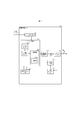
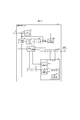
- the moving image decoding device 31 includes an entropy decoding unit 301, a parameter decoding unit (predicted image decoding device) 302, a loop filter 305, a reference picture memory 306, a predicted parameter memory 307, a predicted image generator (predicted image generator) 308, and a reverse. It is composed of a quantization / inverse conversion unit 311 and an addition unit 312. In addition, there is also a configuration in which the loop filter 305 is not included in the moving image decoding device 31 in accordance with the moving image coding device 11 described later.
- the parameter decoding unit 302 further includes a header decoding unit 3020, a CT information decoding unit 3021, and a CU decoding unit 3022 (prediction mode decoding unit), and the CU decoding unit 3022 includes a TU decoding unit 3024. These may be generically called a decoding module.
- the header decoding unit 3020 decodes the parameter set information such as VPS, SPS, PPS, and the slice header (slice information) from the encoded data.
- the CT information decoding unit 3021 decodes the CT from the encoded data.
- the CU decoding unit 3022 decodes the CU from the encoded data.
- the TU decoding unit 3024 decodes the QP update information (quantization correction value) and the quantization prediction error (residual_coding) from the coded data when the TU includes a prediction error.
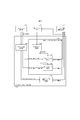
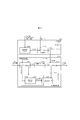
- FIG. 23 is a block diagram showing the relationship between the TU decoding unit 3024 and the inverse conversion unit 3112.
- the stIdx decoding unit 131 of the TU decoding unit 3024 decodes the value stIdx indicating whether or not the secondary conversion is used and the conversion basis from the encoded data, and outputs the value to the secondary conversion unit 31121.
- the mts_idx decoding unit 132 of the TU decoding unit 3024 decodes the value mts_idx indicating the MTS transformation matrix from the encoded data and outputs it to the core conversion unit 31123.
- the width and height of the CU are 4 or more
- the prediction mode is the intra mode
- the number of conversion coefficients in the CU numSigCoeff is a predetermined number THSt (for example).
- SINGLE_TREE is 2, otherwise 1) Decrypts stIdx. If stIdx is 0, the secondary transformation is not applied. If stIdx is 1, the transformation of one of the sets (pairs) of the secondary transformation matrix is shown. If stIdx is 2, the above The transformation of the other of the pairs is shown. Further, the secondary transformation matrix secTransMatrix may be selected not only according to the value of stIdx but also according to the intra prediction mode and the size of the transformation.
- the parameter decoding unit 302 includes an inter-prediction parameter decoding unit 303 and an intra-prediction parameter decoding unit 304 (not shown).
- the prediction image generation unit 308 includes an inter prediction image generation unit 309 and an intra prediction image generation unit 310.
- CTU and CU as the processing unit
- processing is not limited to this example, and processing may be performed in sub-CU units.
- CTU and CU may be read as blocks
- sub-CUs may be read as sub-blocks
- processing may be performed in units of blocks or sub-blocks.
- the entropy decoding unit 301 performs entropy decoding on the coded stream Te input from the outside, separates and decodes each code (syntax element).
- CABAC Context Adaptive Binary Arithmetic Coding
- the probability model of the picture using the same slice type and the same slice level quantization parameter is set from the probability models stored in the memory.
- This initial state is used for encoding and decoding processing.
- the separated codes include prediction information for generating a prediction image, prediction error for generating a difference image, and the like.
- the entropy decoding unit 301 outputs the separated codes to the parameter decoding unit 302.
- the separated code is, for example, the prediction mode predMode.
- the control of which code is decoded is performed based on the instruction of the parameter decoding unit 302.
- FIG. 8 is a flowchart illustrating a schematic operation of the moving image decoding device 31.
- the header decoding unit 3020 decodes the parameter set information such as VPS, SPS, and PPS from the encoded data.
- the header decoding unit 3020 decodes the slice header (slice information) from the encoded data.
- the moving image decoding device 31 derives the decoded image of each CTU by repeating the processes of S1300 to S5000 for each CTU included in the target picture.
- the CT information decoding unit 3021 decodes the CTU from the encoded data.
- the CT information decoding unit 3021 decodes the CT from the encoded data.
- the CU decoding unit 3022 executes S1510 and S1520 to decode the CU from the encoded data.
- the CU decoding unit 3022 decodes CU information, prediction information, TU division flag split_transform_flag, CU residual flags cbf_cb, cbf_cr, cbf_luma, etc. from the encoded data.
- the TU decoding unit 3024 decodes the QP update information (quantization correction value) and the quantization prediction error (residual_coding) from the coded data when the TU contains a prediction error.
- the QP update information is a difference value from the quantization parameter prediction value qPpred, which is the prediction value of the quantization parameter QP.
- the prediction image generation unit 308 generates a prediction image based on the prediction information for each block included in the target CU.
- Inverse quantization / inverse conversion unit 311 executes inverse quantization / inverse conversion processing for each TU included in the target CU.
- the addition unit 312 decodes the target CU by adding the prediction image supplied by the prediction image generation unit 308 and the prediction error supplied by the inverse quantization / inverse conversion unit 311. Generate an image.
- the loop filter 305 applies a loop filter such as a deblocking filter, SAO, or ALF to the decoded image to generate a decoded image.
- a loop filter such as a deblocking filter, SAO, or ALF
- the parameter decoding unit 302 includes an inter-prediction parameter decoding unit 303 and an intra-prediction parameter decoding unit 304 (not shown).
- the prediction image generation unit 308 includes an inter-prediction image generation unit 309 and an intra-prediction image generation unit 310 (not shown).
- the intra prediction parameter decoding unit 304 decodes the intra prediction parameter, for example, the intrapred mode, with reference to the prediction parameter stored in the prediction parameter memory 307, based on the code input from the entropy decoding unit 301.
- the intra prediction parameter decoding unit 304 outputs the decoded intra prediction parameter to the prediction image generation unit 308, and stores it in the prediction parameter memory 307.
- the intra prediction parameter decoding unit 304 may derive an intra prediction mode that differs depending on the brightness and the color difference.
- FIG. 9 is a schematic diagram showing the configuration of the intra-prediction parameter decoding unit 304 of the parameter decoding unit 302.
- the intra prediction parameter decoding unit 304 includes a parameter decoding control unit 3041, a luminance intra prediction parameter decoding unit 3042, and a color difference intra prediction parameter decoding unit 3043.
- the parameter decoding control unit 3041 instructs the entropy decoding unit 301 to decode the syntax element, and receives the syntax element from the entropy decoding unit 301.
- intra_luma_mpm_flag 1
- the parameter decoding control unit 3041 outputs intra_luma_mpm_idx to the MPM parameter decoding unit 30422 in the luminance intra prediction parameter decoding unit 3042.
- the parameter decoding control unit 3041 outputs the intra_luma_mpm_remainder to the non-MPM parameter decoding unit 30423 of the luminance intra prediction parameter decoding unit 3042.
- the parameter decoding control unit 3041 outputs the syntax element of the color difference intra prediction parameter to the color difference intra prediction parameter decoding unit 3043.
- the luminance intra prediction parameter decoding unit 3042 includes an MPM candidate list derivation unit 30421, an MPM parameter decoding unit 30422, and a non-MPM parameter decoding unit 30423 (decoding unit, derivation unit).
- the MPM parameter decoding unit 30422 derives IntraPredModeY with reference to the mpmCandList [] and intra_luma_mpm_idx derived by the MPM candidate list derivation unit 30421, and outputs it to the intra prediction image generation unit 310.
- the non-MPM parameter decoding unit 30423 derives RemIntraPredMode from mpmCandList [] and intra_luma_mpm_remainder, and outputs IntraPredModeY to the intra prediction image generation unit 310.
- the color difference intra prediction parameter decoding unit 3043 derives IntraPredModeC from the syntax element of the color difference intra prediction parameter and outputs it to the intra prediction image generation unit 310.
- the brightness intra-prediction parameter decoding unit 3042 may further decode the flag intra_subpartitions_mode_flag indicating whether or not to perform the intra-sub-division that divides the CU into smaller sub-blocks and performs the intra-prediction. If intra_subpartitions_mode_flag is other than 0, the intra_subpartitions_split_flag is further decoded.
- the intra-sub-division mode is derived by the following equation.
- IntraSubPartSplitType is 0 (ISP_NO_SPLIT)
- IntraSubPartSplitType is 1 (ISP_HOR_SPLIT: horizontal division)
- the CU is vertically divided into 2 to 4 sub-blocks, and intra-prediction, conversion coefficient decoding, and inverse quantization / inverse conversion are performed for each sub-block.
- IntraSubPartSplitType is 2 (ISP_VER_SPLIT: vertical division)
- the CU is divided horizontally into 2 to 4 sub-blocks, and intra-prediction, conversion coefficient decoding, and inverse quantization / inverse conversion are performed for each sub-block.
- the number of subblock divisions NumIntraSubPart is derived by the following formula.
- the loop filter 305 is a filter provided in the coding loop, which removes block distortion and ringing distortion to improve image quality.
- the loop filter 305 applies filters such as a deblocking filter, a sample adaptive offset (SAO), and an adaptive loop filter (ALF) to the decoded image of the CU generated by the addition unit 312.
- filters such as a deblocking filter, a sample adaptive offset (SAO), and an adaptive loop filter (ALF) to the decoded image of the CU generated by the addition unit 312.
- the reference picture memory 306 stores the decoded image of the CU generated by the addition unit 312 at a predetermined position for each target picture and the target CU.
- the prediction parameter memory 307 stores the prediction parameters at a predetermined position for each CTU or CU to be decoded. Specifically, the prediction parameter memory 307 stores the parameters decoded by the parameter decoding unit 302 and the pred mode and the like separated by the entropy decoding unit 301.
- PredMode, prediction parameters, etc. are input to the prediction image generation unit 308. Further, the prediction image generation unit 308 reads the reference picture from the reference picture memory 306. The prediction image generation unit 308 generates a prediction image of a block or a subblock by using the prediction parameter and the read reference picture (reference picture block) in the prediction mode indicated by predMode.
- the reference picture block is a set of pixels on the reference picture (usually called a block because it is rectangular), and is an area to be referred to for generating a predicted image.
- the intra prediction image generation unit 310 performs the intra prediction using the intra prediction parameters input from the intra prediction parameter decoding unit 304 and the reference pixels read from the reference picture memory 306.
- the intra prediction image generation unit 310 reads an adjacent block on the target picture within a predetermined range from the target block from the reference picture memory 306.
- the predetermined range is adjacent blocks on the left, upper left, upper, and upper right of the target block, and the area to be referred to differs depending on the intra prediction mode.
- the intra prediction image generation unit 310 generates a prediction image of the target block by referring to the read decoding pixel value and the prediction mode indicated by IntraPredMode.
- the intra prediction image generation unit 310 outputs the prediction image of the generated block to the addition unit 312.
- the decoded peripheral area adjacent (proximity) to the prediction target block is set as the reference area R.
- the predicted image is generated by extrapolating the pixels on the reference region R in a specific direction.
- the reference area R is an L-shaped area including the left and top of the prediction target block (or further, upper left, upper right, lower left) (for example, the pixels marked with diagonal circles in Example 1 of the reference area in FIG. It may be set as the area shown).
- the intra prediction image generation unit 310 includes a prediction target block setting unit 3101, an unfiltered reference image setting unit 3102 (first reference image setting unit), a filtered reference image setting unit 3103 (second reference image setting unit), and an intra. It includes a prediction unit 3104 and a prediction image correction unit 3105 (prediction image correction unit, filter switching unit, weight coefficient changing unit).
- the intra prediction unit 3104 Based on each reference pixel (unfiltered reference image) on the reference area R, the filtered reference image generated by applying the reference pixel filter (first filter), and the intra prediction mode, the intra prediction unit 3104 is a prediction target block. (Prediction image before correction) is generated and output to the prediction image correction unit 3105.
- the prediction image correction unit 3105 corrects the provisional prediction image according to the intra prediction mode, generates a prediction image (corrected prediction image), and outputs the prediction image.
- the prediction target block setting unit 3101 sets the target CU as the prediction target block, and outputs information (prediction target block information) regarding the prediction target block.
- the prediction target block information includes at least an index indicating the size, position, brightness or color difference of the prediction target block.
- the unfiltered reference image setting unit 3102 sets the adjacent peripheral area of the prediction target block as the reference area R based on the size and position of the prediction target block. Subsequently, each pixel value (unfiltered reference image, boundary pixel) in the reference area R is set with each decoded pixel value at the corresponding position on the reference picture memory 306.
- the line r [x] [-1] of the decoding pixels adjacent to the upper side of the prediction target block shown in Example 1 of the reference area of FIG. 10, and the row r [-1] [y] of the decoding pixels adjacent to the left side of the prediction target block. ] Is an unfiltered reference image.
- the filtered reference image setting unit 3103 applies a reference pixel filter (first filter) to the unfiltered reference image according to the intra prediction mode, and filters each position (x, y) on the reference area R. Derivation of the reference image s [x] [y]. Specifically, a low-pass filter is applied to the unfiltered reference image at the position (x, y) and its surroundings, and the filtered reference image (example 2 of the reference area in FIG. 10) is derived. It is not always necessary to apply the low-pass filter to all the intra-prediction modes, and the low-pass filter may be applied to some of the intra-prediction modes.
- a reference pixel filter first filter
- the filter applied to the unfiltered reference image on the reference area R is called a “reference pixel filter (first filter)", whereas in the prediction image correction unit 3105 described later.
- a filter that corrects a tentatively predicted image is called a “boundary filter (second filter)”.
- the intra prediction unit 3104 generates a tentative prediction image (provisional prediction pixel value, pre-correction prediction image) of the prediction target block based on the intra prediction mode, the unfiltered reference image, and the filtered reference pixel value, and the prediction image correction unit Output to 3105.
- the intra prediction unit 3104 includes a Planar prediction unit 31041, a DC prediction unit 31042, an Angular prediction unit 31043, and an LM prediction unit 31044 inside.
- the intra prediction unit 3104 selects a specific prediction unit according to the intra prediction mode, and inputs an unfiltered reference image and a filtered reference image.
- the relationship between the intra prediction mode and the corresponding prediction unit is as follows.
- Planar Prediction ⁇ ⁇ ⁇ Planar Prediction Department 31041 DC prediction ⁇ ⁇ ⁇ DC prediction unit 31042 ⁇ Angular Prediction ⁇ ⁇ ⁇ Angular Prediction Department 31043 ⁇ LM prediction ⁇ ⁇ ⁇ LM prediction unit 31044 (Planar forecast)
- the Planar prediction unit 31041 linearly adds a plurality of filtered reference images according to the distance between the prediction target pixel position and the reference pixel position to generate a tentative prediction image, and outputs the provisional prediction image to the prediction image correction unit 3105.
- the DC prediction unit 31042 derives a DC prediction value corresponding to the average value of the filtered reference images s [x] [y], and outputs a provisional prediction image q [x] [y] using the DC prediction value as a pixel value. To do.
- the Angular prediction unit 31043 generates a tentative prediction image q [x] [y] using the filtered reference images s [x] [y] in the prediction direction (reference direction) indicated by the intra prediction mode, and the prediction image correction unit. Output to 3105.
- the LM prediction unit 31044 predicts the pixel value of the color difference based on the pixel value of the luminance. Specifically, it is a method of generating a predicted image of a color difference image (Cb, Cr) using a linear model based on a decoded luminance image.
- CCLM Cross-Component Linear Model prediction
- LM prediction is a prediction method that uses a linear model for predicting the color difference from the luminance for one block.
- the prediction image correction unit 3105 corrects the tentative prediction image output from the intra prediction unit 3104 according to the intra prediction mode. Specifically, the prediction image correction unit 3105 weights and adds the unfiltered reference image and the provisional prediction image to each pixel of the provisional prediction image according to the distance between the reference region R and the target prediction pixel (weighted average). By doing so, the predicted image (corrected predicted image) Pred obtained by modifying the provisional predicted image is derived. In some intra-prediction modes, the prediction image correction unit 3105 may not correct the provisional prediction image, and the output of the intra-prediction unit 3104 may be used as the prediction image as it is.
- the inverse quantization / inverse conversion unit 311 inversely quantizes the quantization conversion coefficient qd [] [] input from the entropy decoding unit 301 to obtain the conversion coefficient d [] [].
- This quantization transform coefficient qd [] [] performs frequency conversion such as DCT (Discrete Cosine Transform) and DST (Discrete Sine Transform) on the prediction error in the coding process. It is a coefficient obtained by transforming.
- the inverse quantization / inverse conversion unit 311 performs inverse frequency conversion such as inverse DCT and inverse DST on the obtained conversion coefficient, and calculates a prediction error.
- the inverse quantization / inverse conversion unit 311 outputs the prediction error to the addition unit 312.
- FIG. 12 is a functional block diagram showing a configuration example of the inverse quantization / inverse conversion unit 311.
- the quantization / inverse conversion unit 311 includes an inverse quantization unit 3111 and a conversion unit 3112.
- the inverse quantization unit 3111 dequantizes the quantization conversion coefficient qd [] [] decoded by the TU decoding unit 3024, and derives the conversion coefficient d [] [].
- the inverse quantization unit 3111 outputs the derived conversion coefficient d [] [] to the conversion unit 3112.
- the conversion unit 3112 reversely converts the received conversion coefficient d [] [] for each conversion unit TU, and restores the prediction error r [] [].
- the conversion unit 3112 outputs the restored prediction error r [] [] to the addition unit 312.
- the process of converting the difference image into the conversion coefficient in the image coding apparatus is called forward conversion
- the process of converting the conversion coefficient in the image decoding apparatus into the difference image is called conversion.
- the term "inverse conversion” may be used instead of "conversion” for the conversion process in the conversion unit 3112.
- the conversion unit 3112 includes a secondary conversion unit (second conversion unit) 31121 and a core conversion unit (first conversion unit) 31123.
- the TU decoding unit 3024 further divides the CU into a plurality of subblocks, decodes the conversion coefficient of only one of the plurality of subblocks, and decodes the subblock conversion flag cu_sbt_flag that performs inverse quantization and inverse conversion. You may. When cu_sbt_flag is 1, the flag cu_sbt_quad_flag indicating whether to divide into four subblocks may be further decoded. When cu_sbt_quad_flag is 0, the number of subblocks is 2. When cu_sbt_quad_flag is 1, the number of subblocks is 4. It also decodes the cu_sbt_horizontal_flag, which indicates whether to split horizontally or vertically. It also decodes the cu_sbt_pos_flag, which indicates which subblock contains the conversion factor.
- the scaling unit 31112 scales the conversion coefficient decoded by the TU decoding unit using a weight in coefficient units.
- the quantization matrix m [x] [y] and the scaling factor ls [x] [y] are derived by the following equations.
- the scaling unit 31112 derives dnc [] [] from the product of the scaling factor ls [] [] and the decoded conversion coefficient TransCoeffLevel, and performs inverse quantization.
- dnc [x] [y] (TransCoeffLevel [xTbY] [yTbY] [cIdx] [x] [y] * ls [x] [y] * rectNorm + bdOffset) >> bdShift
- the scaling unit 31112 clips the inverse quantized conversion coefficient to derive d [x] [y].
- d [x] [y] Clip3 (CoeffMin, CoeffMax, dnc [x] [y]) d [x] [y] is transmitted to the core conversion unit 31123 or the secondary conversion unit 31121.
- the secondary conversion unit (second conversion unit) 31121 applies the secondary conversion to the conversion coefficient d [] [] after the inverse quantization and before the core conversion.
- the secondary conversion unit 31121 applies a transformation using a transformation matrix to a part or all of the conversion coefficients d [] [] received from the inverse quantization unit 3111, thereby performing a correction conversion coefficient (second conversion). (Conversion coefficient after conversion by part) d [] [] is restored.
- the secondary conversion unit 31121 applies the secondary conversion to the conversion coefficient d [] [] in a predetermined unit for each conversion unit TU.
- the secondary transformation is applied only in the intra CU, and the transformation basis is determined with reference to the intrapred mode. The selection of the conversion basis will be described later.
- the secondary conversion unit 31121 outputs the restored correction conversion coefficient d [] [] to the core conversion unit 31123.
- the core conversion unit 31123 acquires the conversion coefficient d [] [] or the correction conversion coefficient d [] [] restored by the secondary conversion unit 31121, performs conversion, and derives the prediction error r [] [].
- the core conversion unit 31123 outputs the prediction error r [] [] to the addition unit 312.
- FIG. 19 shows a forward conversion unit 1032 included in the conversion / quantization unit 103 of the moving image coding apparatus 11 and an inverse conversion unit 152 included in the inverse conversion / inverse quantization unit 105.
- the secondary conversion is applied to the conversion coefficient of a part or all of the decoded TU, and the core conversion (DCT2, DST7, etc.) is applied to the conversion coefficient after the secondary conversion.
- FIG. 13 is a diagram illustrating a secondary conversion.
- the conversion coefficient d [] [] in the 4x4 region is stored in the nonZeroSize one-dimensional array u [] in the S2 processing, and the one-dimensional array u [] to the one-dimensional array in the S3 processing.
- the process of converting to v [] and finally storing it in d [] [] in the process of S4 is shown.
- FIG. 24 is a flowchart showing the processing of the secondary conversion.
- the secondary conversion unit 31121 determines the size of the secondary conversion (4x4 or 8x8), the number of conversion coefficients of the output (nStOutSize), and the conversion coefficient of the application (input conversion coefficient) according to the size of the TU (width nTbW, height nTbH). ) Number nonZeroSize and the number of subblocks (numStX, numStY) to which the secondary transformation is applied are derived.
- the secondary conversion unit 31121 When the TU is larger than the specified size, the secondary conversion unit 31121 outputs 48 conversion coefficients by the secondary conversion of RST8x8. Otherwise, RST4x4 secondary conversion outputs 16 conversion coefficients.
- the TU is 4x4
- 16 conversion coefficients are derived from the conversion coefficient of 8 using RST4x4
- the conversion coefficient of 48 is derived from the conversion coefficient of 8 using RST8x8. In other cases, 16 or 48 conversion coefficients are output from 16 conversion coefficients depending on the size of the TU.
- xC and yC are positions on the TU, and are derived from the array DiagScanOrder indicating the scan order and the position x of the conversion coefficient in the subblock.
- the secondary conversion unit 31121 converts u [] (vector F') having a length of nonZeroSize using a conversion basis (matrix) T of the first kind, and outputs a one-dimensional array having a length of nStOutSize. Derivation of v'[] (vector V').
- This conversion can be expressed by the following formula in matrix operation.
- V' T ⁇ F'
- the conversion basis when the conversion size is 4x4 (RST4x4) is called the first type conversion basis T1.
- the conversion basis is called the second type conversion basis T2.
- T1 is a 16x16 (16 rows 16 columns) matrix
- the transformation is 16x1 (16 rows 1 column) vector
- T2 is a 48x16 (48 rows 16 columns) matrix
- the transformation is the product of the 48x16 matrix T and the 16x1 vector F', which is the 48x1 (48 rows 1 column, length 48) vector V', that is. , Derivation of a one-dimensional array v'[] of length 48.
- the secondary conversion unit 31121 includes a set number (stTrSetId) of the secondary conversion derived from the intrapred mode IntraPredMode, stIdx indicating the conversion basis of the secondary conversion decoded from the encoded data, and a secondary conversion size nStSize. Derivation of the corresponding transformation matrix secTranMatrix [] [] (transformation basis T1 or T2) from (nTrS). Further, the secondary conversion unit 31121 performs a multiply-accumulate operation between the transformation matrix and the one-dimensional array u [], as shown in the following equation.
- stTrSetId set number of the secondary conversion derived from the intrapred mode IntraPredMode
- stIdx indicating the conversion basis of the secondary conversion decoded from the encoded data
- nStSize secondary conversion size
- v'[i] Clip3 (CoeffMin, CoeffMax, ⁇ secTransMatrix [j] [i] * u [j])
- i processes 0..nStSize-1.
- CoeffMin and CoeffMax indicate the range of conversion coefficient values.
- the secondary conversion unit 31121 repositions the coefficient v'[] of the converted one-dimensional array at a predetermined position in the TU.
- the secondary conversion unit 31121 arranges a coefficient v'[] having a length of nStOutSize obtained by the above process S3 in the upper left area of the conversion coefficient array d [] [].
- the conversion used in the core conversion is a separation type conversion consisting of a vertical conversion and a horizontal conversion. Further, the transformation that separates the two-dimensional signal in the horizontal direction and the vertical direction may be defined as the first transformation. Further, in the image decoding apparatus, the conversion applied after the second conversion (secondary conversion) may be defined as the first conversion.
- the transformation basis (transformation matrix) of the core transformation is DCT2, DST7, DCT8. In the core conversion, the conversion basis is switched independently for the vertical conversion and the horizontal conversion. The selectable conversion is not limited to the above, and another conversion (conversion basis) can be used.
- DCT2, DST7, DCT8, DST1 and DCT5 may be represented as DCT-II, DST-VII, DCT-VIII, DST-I and DCT-V, respectively. There may be conversion skip as a mode for explicitly skipping core conversion.
- MTS There are explicit MTS and implicit MTS for core conversion.
- decode mts_idx from the encoded data and switch the transformation matrix.
- mts_idx is derived according to the intra prediction mode and block size.
- decoding mts_idx in CU units or TU units is described, but the decoding (switching) unit is not limited to this.
- Mts_idx is a switching index for selecting the conversion basis of core conversion.
- mts_idx has one of the values 0, 1, 2, 3, and 4, and derives the horizontal conversion type trTypeHor and the vertical conversion type trTypeVer.
- the core conversion described above will be specifically described with reference to FIG.
- the core conversion unit 1521 of FIG. 18 is an example of the core conversion unit 31123 of FIG. 12 and the core conversion unit 1521 of FIG.
- the core conversion unit 1521 in FIG. 18 uses the MTS setting unit 15211 that sets the type of conversion used from a plurality of conversion bases and the (corrected) conversion coefficient d [] [] using the derived conversion to predict the residual r [ ] [] Is composed of a coefficient conversion processing unit 15212 for calculating and a matrix conversion processing unit 15213 for performing actual conversion. If no secondary conversion is performed, the modified conversion factor is equal to the conversion factor. When the secondary conversion is performed, the modified conversion factor takes a value different from the conversion factor.
- the MTS setting unit 15211 is composed of an MTS setting unit 152111 that determines the method for deriving the index mts_ids of the conversion to be used, and an implicit MTS setting unit 152112 that implicitly derives mts_idx.
- the MTS setting unit 152111 selects whether to perform explicit MTS, implicit MTS, or not MTS.
- the MTS setting unit 152111 uses the explicit MTS when the explicit MTS is valid (when the sps_explicit_mts_flag is 1), and uses the mts_idx decoded from the encoded data in the subsequent processing.
- the explicitMtsEnabled flag for whether explicit MTS is enabled may be set individually for intramode and intermode.
- PredMode is intermode (other than MODE_INTRA) and sps_explicit_mts_inter_enabled_flag is 1, or if PredMode is intramode (MODE_INTRA) and sps_explicit_mts_intra_enabled_flag is 1, it is determined that explicit MTS is valid and the encoded data.
- PredMode is intramode (MODE_INTRA) and sps_explicit_mts_intra_enabled_flag is 1, it is determined that explicit MTS is valid and the encoded data.
- You may decrypt mts_idx from.
- the TU decoding unit 3024 decodes mts_idx from the encoded data when the explicit MTS is valid (sps_explicit_mts_flag is 1).
- conversion may be performed by combining DST1 and DCT4, and pre-processing and post-processing and DCT2.
- the effective range of MTS can be limited, which has the effect of simplifying coding.
- restriction example 2 since the secondary conversion is not performed in the case of DCT8 whose effect overlaps with the secondary conversion, the overhead due to mts_idx is reduced and the coding efficiency is improved.
- An image decoding device including a conversion unit that converts a conversion coefficient for each TU, and the conversion unit applies a conversion using a transformation matrix to the input conversion coefficient when the secondary conversion is effective.
- the second range includes the first range.
- the TU decoding unit decodes mts_idx.
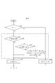
- the implicit MTS setting unit 152112 performs the following processing in the case of an implicit MTS.
- the implicit MTS setting unit 152112 is set to 1 (DST7) as tyTypeHor, tyTypeVer according to cu_sbt_horizontal_flag and cu_sbt_pos_flag as shown in FIG. ) Or 2 (DCT8).
- the implicit MTS setting unit 152112 has either 0 (DCT2) or 1 (DST7) as tyTypeHor or tyTypeVer depending on the TU size (width nTbW, height nTbH).
- the horizontal conversion type trTypeHor is set to 1 (DCT1) when the width nTbW is within a predetermined range (S1301) (S1302), and 0 (DCT2) in other cases. ) (S1303).
- the vertical conversion type trTypeVer 1 (DCT1) is set when the height nTbH is within a predetermined range (S1304) (S1305), and 0 (DCT2) is set otherwise (S1306).
- the predetermined range is not limited to the above. For example, it may be as follows.
- the default implicit MTS above is the most common implicit MTS mode.
- SM000 may be performed before SM001 described above.
- FIG. 21 is a diagram illustrating the operation of the implicit MTS setting unit 152112.
- SM003' may be performed instead of the above SM003.
- the implicit MTS setting unit 152112 sets 0 (DCT2) or 1 (DCT2) or 1 (tyTypeHor, tyTypeVer) depending on the secondary conversion and TU size (width nTbW, height nTbH).
- the MTS setting unit 15211 derives the index trType of the conversion set to be used by the following formula and outputs it to the coefficient conversion processing unit 15212.
- the coefficient conversion processing unit 15212 outputs the input trType to the transformation matrix derivation unit 152131.
- the MTS setting unit 152111 derives a value indicating the MTS to be used by the following formula.
- the coefficient conversion processing unit 15212 is composed of a vertical conversion unit 152121 that performs vertical conversion on the correction conversion coefficient d [] [] and a horizontal conversion unit 152123 that performs horizontal conversion.
- the vertical conversion unit 152121 (coefficient conversion processing unit 15212) performs the following processing.
- nTbS is the height of TU nTbH.
- transMatrix ⁇ 29, 55, 74, 84 ⁇ ⁇ 74, 74, 0, -74 ⁇ ⁇ 84, -29, -74 , 55 ⁇ ⁇ 55, -84, 74, -29 ⁇ .
- the intermediate clip unit 152122 derives the intermediate value g [] [] by clipping the intermediate value e [] [] and sends it to the horizontal conversion unit 152123.
- g [x] [y] Clip3 (coeffMin, coeffMax, (e [x] [y] + 64) >> 7)
- the above equations 64 and 7 are numerical values determined by the bit depth of the conversion basis, and the above equation assumes that the conversion basis is 7 bits. Also, coeffMin and coeffMax are the minimum and maximum values of clipping.
- the horizontal conversion unit 152123 (coefficient conversion processing unit 15212) performs the following processing.
- nTbS is the width of TU, nTbW.
- the horizontal conversion unit 152123 converts the intermediate value g [x] [y] into the predicted residual r [x] [y] by the horizontal one-dimensional conversion.
- the predicted residual r [] [] is sent from the horizontal converter 152123 to the adder 312.
- the vertical conversion unit 152121 and the horizontal conversion unit 152123 perform conversion by the matrix conversion processing unit 15213.
- the matrix conversion processing unit 15213 is composed of a conversion matrix derivation unit 152131 and a conversion processing unit 152132.
- the transformation matrix derivation unit 152131 derives the transformation matrix transMatrix [] [] according to the length of the TU (nTbW, nTbH) and the index tyType (trTypeHor, trTypeVer) of the core transformation.
- the matrix conversion processing unit 15213 converts the one-dimensional array xx [j] input using the derived transformation matrix transMatrix [] [] into the one-dimensional array yy [i], and performs vertical conversion and horizontal conversion.
- the conversion coefficient d [x] [j] of the x column is input as the one-dimensional conversion coefficient xx [j] for conversion.
- the intermediate coefficient g [j] [y] in the y row is input as xx [j] for conversion.
- the TU decoding unit 3024 may limit the range of the value of stIdx to be decoded depending on whether the value of mts_idx is valid or not.
- the variable stIdx indicating the type of the secondary conversion is decoded only when the conversion in a predetermined range is performed by the MTS, so that the effective range of the secondary conversion is limited, so that the coding is simplified. Play. Further, for example, in the limitation example 2, since the secondary conversion is not performed in the case of DCT8 whose effect overlaps with the secondary conversion, the overhead due to stIdx is reduced and the coding efficiency is improved.
- the addition unit 312 adds the prediction image of the block input from the prediction image generation unit 308 and the prediction error input from the inverse quantization / inverse conversion unit 311 for each pixel to generate a decoded image of the block.
- the addition unit 312 stores the decoded image of the block in the reference picture memory 306, and outputs the decoded image to the loop filter 305.
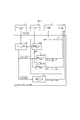
- FIG. 16 is a block diagram showing the configuration of the moving image coding device 11 according to the present embodiment.
- the moving image coding device 11 includes a prediction image generation unit 101, a subtraction unit 102, a conversion / quantization unit 103, an inverse quantization / inverse conversion unit 105, an addition unit 106, a loop filter 107, and a prediction parameter memory (prediction parameter storage unit).
- Frame memory 108, reference picture memory (reference image storage unit, frame memory) 109, coding parameter determination unit 110, parameter coding unit 111, and entropy coding unit 104.
- the predicted image generation unit 101 generates a predicted image for each CU, which is a region in which each picture of the image T is divided.
- the prediction image generation unit 101 has the same operation as the prediction image generation unit 308 described above, and the description thereof will be omitted.
- the subtraction unit 102 subtracts the pixel value of the predicted image of the block input from the prediction image generation unit 101 from the pixel value of the image T to generate a prediction error.
- the subtraction unit 102 outputs the prediction error to the conversion / quantization unit 103.
- the conversion / quantization unit 103 calculates the conversion coefficient by frequency conversion for the prediction error input from the subtraction unit 102, and derives the quantization conversion coefficient by quantization.
- the conversion / quantization unit 103 outputs the quantization conversion coefficient to the entropy coding unit 104 and the inverse quantization / inverse conversion unit 105.
- the conversion / quantization unit 103 includes a forward core conversion 10321 (first conversion unit) and a forward secondary conversion unit 10322 (second conversion unit).
- the processing S1-S4 of the secondary conversion applied to the moving image decoding device 31 is almost the same except that the processing S1, S4, S3, and S2 are applied in the reverse order. I do.
- the forward secondary conversion unit 10322 performs the same processing as the secondary conversion unit 31121 except that the input and output of the secondary conversion have lengths nStOutSize and nonZeroSize, respectively.
- the forward / secondary conversion unit 10322 derives a one-dimensional array v [] of nStOutSize (or nStSize * nStSize) from the conversion coefficient d [] [] at a predetermined position in the TU.
- the forward secondary conversion unit 10322 performs the following conversion from the one-dimensional array v [] (vector V) of nStOutSize and the transformation matrix T [] [], and the one-dimensional array u [] (vector F) of nonZeroSize To get.
- trans (T) is the transpose matrix of T.
- the secondary conversion unit may derive a one-dimensional array u [] (vector F) by the following equation.
- Tinv is the inverse matrix of T.
- T is composed of a first-class conversion basis T1 and a second-class conversion basis T2.
- the secondary conversion unit may set trans (T) of T to Tinv by using an orthogonal matrix with respect to T.
- the secondary conversion unit uses a matrix that is a constant multiple of the inverse matrix as Tinv, but the inverse matrix may be used as it is for the transposed matrix.
- the forward / secondary conversion unit 10322 rearranges the nonZeroSize one-dimensional array u [] into a two-dimensional array to derive the conversion coefficient d [] [].
- xC (xSbIdx ⁇ log2StSize) + DiagScanOrder [log2StSize] [log2StSize] [x] [0]
- the inverse quantization / inverse conversion unit 105 is the same as the inverse quantization / inverse conversion unit 311 (FIG. 15) in the moving image decoding device 31, and the description thereof will be omitted.
- the calculated prediction error is output to the addition unit 106.
- the quantization conversion coefficient is input from the conversion / quantization unit 103 to the entropy coding unit 104, and the coding parameter is input from the parameter coding unit 111.
- the coding parameter is, for example, predMode.
- the entropy coding unit 104 entropy-encodes the division information, prediction parameters, quantization conversion coefficient, etc., generates a coded stream Te, and outputs the coded stream Te.
- the parameter coding unit 111 includes a header coding unit 1110 (not shown), a CT information coding unit 1111, a CU coding unit 1112 (prediction mode coding unit), an inter prediction parameter coding unit 112, and an intra prediction parameter coding unit. It has 113.
- the CU coding unit 1112 further includes a TU coding unit 1114.
- the parameter coding unit 111 performs parameter coding processing such as header information, division information, prediction information, and quantization conversion coefficient.
- the CT information coding unit 1111 encodes QT, MT (BT, TT) division information, etc. from the coded data.
- the CU coding unit 1112 encodes CU information, prediction information, TU division flag, CU residual flag, etc.
- the TU coding unit 1114 encodes the QP update information (quantization correction value) and the quantization prediction error (residual_coding) when the TU contains a prediction error.
- the CT information coding unit 1111 and the CU coding unit 1112 supply syntax elements such as inter prediction parameters, intra prediction parameters (intra_luma_mpm_flag, intra_luma_mpm_idx, intra_luma_mpm_remainder), and quantization conversion coefficients to the entropy coding unit 104.
- the intra prediction parameter coding unit 113 derives a format for coding (for example, intra_luma_mpm_idx, intra_luma_mpm_remainder, etc.) from the IntraPredMode input from the coding parameter determination unit 110.
- the intra prediction parameter coding unit 113 includes a configuration that is partially the same as the configuration in which the intra prediction parameter decoding unit 304 derives the intra prediction parameter.
- FIG. 17 is a schematic diagram showing the configuration of the intra-prediction parameter coding unit 113 of the parameter coding unit 111.
- the intra prediction parameter coding unit 113 includes a parameter coding control unit 1131, a luminance intra prediction parameter derivation unit 1132, and a color difference intra prediction parameter derivation unit 1133.
- IntraPredModeY and IntraPredModeC are input from the coding parameter determination unit 110 to the parameter coding control unit 1131.
- the parameter coding control unit 1131 determines the intra_luma_mpm_flag by referring to the mpmCandList [] of the MPM candidate list derivation unit 30421. Then, intra_luma_mpm_flag and IntraPredModeY are output to the luminance intra prediction parameter derivation unit 1132.
- IntraPredModeC is output to the color difference intra prediction parameter derivation unit 1133.
- the luminance intra prediction parameter derivation unit 1132 includes an MPM candidate list derivation unit 30421 (candidate list derivation unit), an MPM parameter derivation unit 11322, and a non-MPM parameter derivation unit 11323 (encoding unit, derivation unit). To.
- the MPM candidate list derivation unit 30421 derives mpmCandList [] by referring to the intra prediction mode of the adjacent block stored in the prediction parameter memory 108.
- the MPM parameter derivation unit 11322 derives intra_luma_mpm_idx from IntraPredModeY and mpmCandList [] when intra_luma_mpm_flag is 1, and outputs it to the entropy coding unit 104.
- the non-MPM parameter derivation unit 11323 derives RemIntraPredMode from IntraPredModeY and mpmCandList [] when intra_luma_mpm_flag is 0, and outputs intra_luma_mpm_remainder to the entropy encoding unit 104.
- the color difference intra prediction parameter derivation unit 1133 derives intra_chroma_pred_mode from IntraPredModeY and IntraPredModeC and outputs it.
- the addition unit 106 adds the pixel value of the prediction image of the block input from the prediction image generation unit 101 and the prediction error input from the inverse quantization / inverse conversion unit 105 for each pixel to generate a decoded image.
- the addition unit 106 stores the generated decoded image in the reference picture memory 109.
- the loop filter 107 applies a deblocking filter, SAO, and ALF to the decoded image generated by the addition unit 106.
- the loop filter 107 does not necessarily have to include the above three types of filters, and may have, for example, a configuration of only a deblocking filter.
- the prediction parameter memory 108 stores the prediction parameters generated by the coding parameter determination unit 110 at predetermined positions for each target picture and CU.
- the reference picture memory 109 stores the decoded image generated by the loop filter 107 at a predetermined position for each target picture and CU.
- the coding parameter determination unit 110 selects one set from a plurality of sets of coding parameters.
- the coding parameter is the above-mentioned QT, BT or TT division information, prediction parameter, or a parameter to be coded generated in connection with these.
- the prediction image generation unit 101 generates a prediction image using these coding parameters.
- the coding parameter determination unit 110 calculates the RD cost value indicating the magnitude of the amount of information and the coding error for each of the plurality of sets.
- the coding parameter determination unit 110 selects the set of coding parameters that minimizes the calculated cost value.
- the entropy coding unit 104 outputs the selected set of coding parameters as the coding stream Te.
- the coding parameter determination unit 110 stores the determined coding parameter in the prediction parameter memory 108.
- a part of the moving image coding device 11 and the moving image decoding device 31 in the above-described embodiment for example, the entropy decoding unit 301, the parameter decoding unit 302, the loop filter 305, the predicted image generation unit 308, and the inverse quantization / reverse.
- the parameter coding unit 111 may be realized by a computer.
- the program for realizing this control function may be recorded on a computer-readable recording medium, and the program recorded on the recording medium may be read by the computer system and executed.
- the "computer system” referred to here is a computer system built in any of the moving image coding device 11 and the moving image decoding device 31, and includes hardware such as an OS and peripheral devices.
- the "computer-readable recording medium” refers to a portable medium such as a flexible disk, a magneto-optical disk, a ROM, or a CD-ROM, or a storage device such as a hard disk built in a computer system.
- a "computer-readable recording medium” is a medium that dynamically holds a program for a short period of time, such as a communication line when a program is transmitted via a network such as the Internet or a communication line such as a telephone line.
- a program may be held for a certain period of time, such as a volatile memory inside a computer system serving as a server or a client.
- the above-mentioned program may be a program for realizing a part of the above-mentioned functions, and may be a program for realizing the above-mentioned functions in combination with a program already recorded in the computer system.
- a part or all of the moving image coding device 11 and the moving image decoding device 31 in the above-described embodiment may be realized as an integrated circuit such as an LSI (Large Scale Integration).
- LSI Large Scale Integration
- Each functional block of the moving image coding device 11 and the moving image decoding device 31 may be made into a processor individually, or a part or all of them may be integrated into a processor.
- the method of making an integrated circuit is not limited to LSI, and may be realized by a dedicated circuit or a general-purpose processor. Further, when an integrated circuit technology that replaces an LSI appears due to advances in semiconductor technology, an integrated circuit based on this technology may be used.
- the moving image coding device 11 and the moving image decoding device 31 described above can be mounted on and used in various devices for transmitting, receiving, recording, and reproducing moving images.
- the moving image may be a natural moving image captured by a camera or the like, or an artificial moving image (including CG and GUI) generated by a computer or the like.
- moving image coding device 11 and moving image decoding device 31 can be used for transmitting and receiving moving images.
- FIG. 2 shows a block diagram showing the configuration of the transmission device PROD_A equipped with the moving image coding device 11.
- the transmitter PROD_A has a coding unit PROD_A1 that obtains encoded data by encoding a moving image, and a modulation signal by modulating a carrier wave with the coded data obtained by the coding unit PROD_A1. It includes a modulation unit PROD_A2 to obtain and a transmission unit PROD_A3 to transmit the modulation signal obtained by the modulation unit PROD_A2.
- the moving image coding device 11 described above is used as the coding unit PROD_A1.
- the transmitter PROD_A has a camera PROD_A4 for capturing a moving image, a recording medium PROD_A5 for recording a moving image, an input terminal PROD_A6 for inputting a moving image from the outside, and a moving image as a source of the moving image to be input to the coding unit PROD_A1.
- An image processing unit A7 for generating or processing an image may be further provided. In the figure, the configuration in which the transmitter PROD_A is provided with all of these is illustrated, but some of them may be omitted.
- the recording medium PROD_A5 may be a recording of an unencoded moving image, or a moving image encoded by a recording coding method different from the transmission coding method. It may be a thing. In the latter case, a decoding unit (not shown) that decodes the coded data read from the recording medium PROD_A5 according to the coding method for recording may be interposed between the recording medium PROD_A5 and the coding unit PROD_A1.
- FIG. 2 shows a block diagram showing the configuration of the receiving device PROD_B equipped with the moving image decoding device 31.
- the receiving device PROD_B is obtained by a receiving unit PROD_B1 that receives a modulated signal, a demodulating unit PROD_B2 that obtains coded data by demodulating the modulated signal received by the receiving unit PROD_B1, and a demodulating unit PROD_B2. It includes a decoding unit PROD_B3 that obtains a moving image by decoding the coded data.
- the moving image decoding device 31 described above is used as the decoding unit PROD_B3.
- the receiving device PROD_B is a display PROD_B4 for displaying the moving image, a recording medium PROD_B5 for recording the moving image, and an output terminal for outputting the moving image to the outside as a supply destination of the moving image output by the decoding unit PROD_B3. It may also have PROD_B6. In the figure, the configuration in which the receiving device PROD_B is provided with all of these is illustrated, but some of them may be omitted.
- the recording medium PROD_B5 may be used for recording an unencoded moving image, or may be encoded by a recording encoding method different from the transmission coding method. You may. In the latter case, a coding unit (not shown) that encodes the moving image acquired from the decoding unit PROD_B3 according to the recording coding method may be interposed between the decoding unit PROD_B3 and the recording medium PROD_B5.
- the transmission medium for transmitting the modulated signal may be wireless or wired.
- the transmission mode for transmitting the modulated signal may be broadcasting (here, a transmission mode in which the destination is not specified in advance) or communication (here, transmission in which the destination is specified in advance). Refers to an aspect). That is, the transmission of the modulated signal may be realized by any of wireless broadcasting, wired broadcasting, wireless communication, and wired communication.
- a broadcasting station (broadcasting equipment, etc.) / receiving station (television receiver, etc.) of terrestrial digital broadcasting is an example of a transmitting device PROD_A / receiving device PROD_B that transmits and receives modulated signals by radio broadcasting.
- a broadcasting station (broadcasting equipment, etc.) / receiving station (television receiver, etc.) of cable television broadcasting is an example of a transmitting device PROD_A / receiving device PROD_B that transmits and receives modulated signals by wired broadcasting.
- servers workstations, etc.
- clients television receivers, personal computers, smartphones, etc.
- VOD Video On Demand
- video sharing services using the Internet are transmitters that send and receive modulated signals via communication.
- PROD_A / receiver PROD_B usually, in LAN, either wireless or wired is used as a transmission medium, and in WAN, wired is used as a transmission medium.
- personal computers include desktop PCs, laptop PCs, and tablet PCs. Smartphones also include multifunctional mobile phone terminals.
- the client of the video sharing service has a function of decoding the encoded data downloaded from the server and displaying it on the display, as well as a function of encoding the moving image captured by the camera and uploading it to the server. That is, the client of the video sharing service functions as both the transmitting device PROD_A and the receiving device PROD_B.
- moving image coding device 11 and moving image decoding device 31 can be used for recording and reproducing moving images.
- FIG. 3 shows a block diagram showing the configuration of the recording device PROD_C equipped with the above-mentioned moving image coding device 11.
- the recording device PROD_C has a coding unit PROD_C1 that obtains coded data by encoding a moving image and a writing unit PROD_C2 that writes the coded data obtained by the coding unit PROD_C1 to the recording medium PROD_M. And have.
- the moving image coding device 11 described above is used as the coding unit PROD_C1.
- the recording medium PROD_M may be of a type built in the recording device PROD_C, such as (1) HDD (Hard Disk Drive) or SSD (Solid State Drive), or (2) SD memory. It may be of a type that is connected to the recording device PROD_C, such as a card or USB (Universal Serial Bus) flash memory, or (3) DVD (Digital Versatile Disc: registered trademark) or BD (Blu-ray). It may be loaded in a drive device (not shown) built in the recording device PROD_C, such as Disc (registered trademark).
- the recording device PROD_C has a camera PROD_C3 that captures a moving image, an input terminal PROD_C4 for inputting a moving image from the outside, and a reception for receiving the moving image as a source of the moving image to be input to the coding unit PROD_C1.
- a unit PROD_C5 and an image processing unit PROD_C6 for generating or processing an image may be further provided. In the figure, the configuration in which the recording device PROD_C is provided with all of these is illustrated, but some of them may be omitted.
- the receiving unit PROD_C5 may receive an unencoded moving image, or receives coded data encoded by a transmission coding method different from the recording coding method. It may be something to do. In the latter case, it is preferable to interpose a transmission decoding unit (not shown) between the receiving unit PROD_C5 and the coding unit PROD_C1 to decode the coded data encoded by the transmission coding method.
- Examples of such a recording device PROD_C include a DVD recorder, a BD recorder, an HDD (Hard Disk Drive) recorder, and the like (in this case, the input terminal PROD_C4 or the receiving unit PROD_C5 is the main source of moving images). ..
- a camcorder in this case, the camera PROD_C3 is the main source of moving images
- a personal computer in this case, the receiving unit PROD_C5 or the image processing unit C6 is the main source of moving images
- a smartphone this In this case, the camera PROD_C3 or the receiving unit PROD_C5 is the main source of moving images
- the recording device PROD_C is also examples of such a recording device PROD_C.
- FIG. 3 shows a block diagram showing the configuration of the playback device PROD_D equipped with the above-mentioned moving image decoding device 31.
- the playback device PROD_D includes a reading unit PROD_D1 that reads the coded data written in the recording medium PROD_M, and a decoding unit PROD_D2 that obtains a moving image by decoding the coded data read by the reading unit PROD_D1. , Is equipped.
- the moving image decoding device 31 described above is used as the decoding unit PROD_D2.
- the recording medium PROD_M may be of a type built in the playback device PROD_D, such as (1) HDD or SSD, or (2) such as an SD memory card or USB flash memory. It may be of a type connected to the playback device PROD_D, or may be loaded into a drive device (not shown) built in the playback device PROD_D, such as (3) DVD or BD. Good.
- the playback device PROD_D has a display PROD_D3 for displaying the moving image, an output terminal PROD_D4 for outputting the moving image to the outside, and a transmitting unit for transmitting the moving image as a supply destination of the moving image output by the decoding unit PROD_D2. It may also have PROD_D5. In the figure, the configuration in which the playback device PROD_D is provided with all of these is illustrated, but some of them may be omitted.
- the transmission unit PROD_D5 may transmit an unencoded moving image, or transmits coded data encoded by a transmission coding method different from the recording coding method. It may be something to do. In the latter case, it is preferable to interpose a coding unit (not shown) that encodes the moving image by a coding method for transmission between the decoding unit PROD_D2 and the transmitting unit PROD_D5.
- Examples of such a playback device PROD_D include a DVD player, a BD player, an HDD player, and the like (in this case, the output terminal PROD_D4 to which a television receiver or the like is connected is the main supply destination of moving images). ..
- a television receiver in this case, display PROD_D3 is the main supply destination of moving images
- digital signage also called electronic signage or electronic bulletin board, etc.
- display PROD_D3 or transmitter PROD_D5 is the main supply destination of moving images.
- desktop PC in this case, output terminal PROD_D4 or transmitter PROD_D5 is the main supply destination of moving images
- laptop or tablet PC in this case, display PROD_D3 or transmitter PROD_D5 is video
- An example of such a playback device PROD_D is a smartphone (in this case, the display PROD_D3 or the transmitter PROD_D5 is the main supply destination of the moving image) and the like (which is the main supply destination of the image).
- each block of the moving image decoding device 31 and the moving image coding device 11 described above may be realized in hardware by a logic circuit formed on an integrated circuit (IC chip), or may be realized by hardware, or a CPU (Central Processing). It may be realized by software using Unit).
- IC chip integrated circuit
- CPU Central Processing
- each of the above devices is a CPU that executes an instruction of a program that realizes each function, a ROM (Read Only Memory) that stores the above program, a RAM (RandomAccess Memory) that expands the above program, the above program, and various data. It is equipped with a storage device (recording medium) such as a memory for storing the data.
- a storage device such as a memory for storing the data.
- an object of the embodiment of the present invention is a record in which the program code (execution format program, intermediate code program, source program) of the control program of each of the above devices, which is software for realizing the above-mentioned functions, is recorded readable by a computer. It can also be achieved by supplying the medium to each of the above devices and having the computer (or CPU or MPU) read and execute the program code recorded on the recording medium.
- Examples of the recording medium include tapes such as magnetic tapes and cassette tapes, magnetic disks such as floppy (registered trademark) disks / hard disks, and CD-ROMs (Compact Disc Read-Only Memory) / MO disks (Magneto-Optical discs).
- tapes such as magnetic tapes and cassette tapes
- magnetic disks such as floppy (registered trademark) disks / hard disks
- CD-ROMs Compact Disc Read-Only Memory
- MO disks Magnetic-Optical discs
- IC cards memory cards
- Cards such as optical cards
- EPROM Erasable Programmable Read-Only Memory
- EEPROM Electrically Erasable and Programmable Read-Only Memory: registered trademark
- Semiconductor memories such as flash ROM, or PLD (Programmable)
- Logic circuits such as logic device) and FPGA (Field Programmable Gate Array) can be used.
- each of the above devices may be configured to be connectable to a communication network, and the above program code may be supplied via the communication network.
- This communication network is not particularly limited as long as it can transmit the program code.
- Internet intranet, extranet, LAN (Local Area Network), ISDN (Integrated Services Digital Network), VAN (Value-Added Network), CATV (Community Antenna television / Cable Television) communication network, virtual private network (Virtual Private) Network), telephone line network, mobile communication network, satellite communication network, etc.
- the transmission medium constituting this communication network may be any medium as long as it can transmit the program code, and is not limited to a specific configuration or type.
- the embodiment of the present invention can also be realized in the form of a computer data signal embedded in a carrier wave, in which the program code is embodied by electronic transmission.
- the embodiment of the present invention is suitably applied to a moving image decoding device that decodes encoded data in which image data is encoded, and a moving image coding device that generates encoded data in which image data is encoded. be able to. Further, it can be suitably applied to the data structure of the coded data generated by the moving image coding device and referenced by the moving image decoding device.
- Video decoding device 301 Entropy Decryptor 302 Parameter decoder 3020 Header decoder 303 Inter prediction parameter decoding unit 304 Intra Prediction Parameter Decoder 308 Prediction image generator 309 Inter-prediction image generator 310 Intra prediction image generator 311 Inverse quantization / inverse conversion 312 Addition part 11 Video coding device 101 Predictive image generator 102 Subtraction section 103 Conversion / Quantization Department 104 Entropy encoding section 105 Inverse quantization / inverse conversion 107 Loop filter 110 Coded parameter determination unit 111 Parameter encoding section 112 Inter-prediction parameter encoding section 113 Intra Prediction Parameter Encoding Unit 1110 Header encoding 1111 CT information coding unit 1112 CU encoding unit (prediction mode encoding unit) 1114 TU coder 3111 Inverse quantization unit 3112 Inverse converter 31121 Secondary converter 31112 Scaling section 31123 Core converter 10322 Forward secondary converter 10323 Forward core converter
Abstract
There is a problem that the performance of implicit MTS when combined with secondary transform results in a loss. The present invention provides an image decoding device with which it is possible to more suitably apply transform by MTS and secondary transform. A moving-image decoding device including: a second transform unit which, when secondary transform is enabled, applies a transform that uses a transform matrix for a transform coefficient and corrects the transform coefficient; a first transform unit for applying a separated transform composed of vertical and horizontal transforms to the transform coefficient; and an implicit transform setting unit which, when the secondary transform is enabled and when an intra-sub-division mode is unused and a sub-block transform is unused, turns implicit transform off, and when the implicit transform is on, derives a horizontal transform type in accordance with the width of a target TU and derives a vertical transform type in accordance with the height of the target TU. The first transform unit performs a transform that corresponds to the vertical transform type and a transform that corresponds to the horizontal transform type.
Description
本発明の実施形態は、画像復号装置及び画像符号化装置に関する。
An embodiment of the present invention relates to an image decoding device and an image coding device.
画像を効率的に伝送又は記録するために、画像を符号化することによって符号化データを生成する画像符号化装置、及び、当該符号化データを復号することによって復号画像を生成する画像復号装置が用いられている。
In order to efficiently transmit or record an image, an image coding device that generates encoded data by encoding the image and an image decoding device that generates a decoded image by decoding the encoded data It is used.
具体的な画像符号化方式としては、例えば、H.264/AVCやHEVC(High-Efficiency VideoCoding)等が挙げられる。
Specific image coding methods include, for example, H.264 / AVC and HEVC (High-Efficiency Video Coding).
このような画像符号化方式においては、画像を構成する画像(ピクチャ)は、画像を分割することにより得られるスライス、スライスを分割することにより得られる符号化ツリーユニット(CTU:Coding Tree Unit)、符号化ツリーユニットを分割することで得られる符号化単位(符号化ユニット(Coding Unit:CU)と呼ばれることもある)、及び、符号化単位を分割することより得られる変換ユニット(TU:Transform Unit)からなる階層構造により管理され、CU毎に符号化/復号される。
In such an image coding method, the image (picture) constituting the image is a slice obtained by dividing the image, a coded tree unit (CTU: Coding Tree Unit) obtained by dividing the slice, and the like. A coding unit (sometimes called a coding unit (CU)) obtained by dividing a coding tree unit, and a conversion unit (TU: Transform Unit) obtained by dividing a coding unit. ) Is managed by a hierarchical structure, and each CU is encoded / decoded.
また、このような画像符号化方式においては、通常、入力画像を符号化/復号することによって得られる局所復号画像に基づいて予測画像が生成され、当該予測画像を入力画像(原画像)から減算して得られる予測誤差(「差分画像」又は「残差画像」と呼ぶこともある)が符号化される。予測画像の生成方法としては、画面間予測(インター予測)、及び、画面内予測(イントラ予測)が挙げられる。
Further, in such an image coding method, a predicted image is usually generated based on a locally decoded image obtained by encoding / decoding an input image, and the predicted image is subtracted from the input image (original image). The prediction error (sometimes referred to as a "difference image" or "residual image") thus obtained is encoded. Examples of the method for generating a prediction image include inter-screen prediction (inter-screen prediction) and in-screen prediction (intra-prediction).
また、近年の画像符号化及び復号技術として非特許文献1、非特許文献2が挙げられる。非特許文献1には、変換行列を符号化データ中の明示的シンタックスもしくは暗黙的なブロックサイズに応じて切り替えるマルチ変換選択(Multiple Transform Selection、MTS)と呼ばれる技術が開示されている。非特許文献2には、変換ユニット毎に予測誤差の変換後の各係数をRST(Reduced Secondary Transform)変換、すなわち、セカンダリ変換によって変換して変換係数を導出する画像符号化装置が開示されている。また、非特許文献2には、変換ユニット毎に変換係数をセカンダリ変換によって逆変換する画像復号装置が開示されている。
In addition, Non-Patent Document 1 and Non-Patent Document 2 are mentioned as recent image coding and decoding techniques. Non-Patent Document 1 discloses a technique called Multiple Transform Selection (MTS) that switches a transformation matrix according to an explicit syntax or an implicit block size in coded data. Non-Patent Document 2 discloses an image coding device that derives a conversion coefficient by converting each coefficient after conversion of a prediction error for each conversion unit by RST (Reduced Secondary Transform) conversion, that is, secondary conversion. .. Further, Non-Patent Document 2 discloses an image decoding device that reversely converts the conversion coefficient for each conversion unit by secondary conversion.
非特許文献1のようなセカンダリ変換及びセカンダリ変換に関する技術において、セカンダリ変換とMTSによる変換を組み合わせた場合の性能が十分ではないという課題がある。特に、暗黙的MTSの性能がセカンダリ変換と組み合わせた場合にロスとなるというという課題がある。
In the technology related to secondary conversion and secondary conversion as in Non-Patent Document 1, there is a problem that the performance when the secondary conversion and the conversion by MTS are combined is not sufficient. In particular, there is a problem that the performance of the implicit MTS becomes a loss when combined with the secondary conversion.
本発明は、より好適にMTSによる変換およびセカンダリ変換を適用することができる画像復号装置及びその関連技術を提供することを目的とする。
An object of the present invention is to provide an image decoding apparatus and related technology to which conversion by MTS and secondary conversion can be more preferably applied.
本発明の一態様に係る動画像復号装置は、変換ユニット毎に変換係数を変換する画像復号装置であって、セカンダリ変換が有効である場合に、上記変換係数に変換行列を用いた変換を適用して上記変換係数を修正する第2の変換部と、上記変換係数に対して、垂直変換と水平変換から構成される分離型変換を適用する第1の変換部と、上記セカンダリ変換が有効であり、イントラサブ分割モードが利用されず、かつ、サブブロック変換が利用されない場合、暗黙的変換をオフとし、上記暗黙的変換がオンの場合には、対象TUの幅に応じて水平変換タイプを導出し、対象TUの高さに応じて垂直変換タイプを導出する暗黙的変換設定部と、を含み、上記第1の変換部は、上記垂直変換タイプに応じた変換と、上記水平変換タイプとに応じた変換を行うことを特徴とする。
The moving image decoding device according to one aspect of the present invention is an image decoding device that converts a conversion coefficient for each conversion unit, and when secondary conversion is effective, a conversion using a conversion matrix is applied to the conversion coefficient. The second conversion unit that corrects the conversion coefficient, the first conversion unit that applies the separation type conversion composed of the vertical conversion and the horizontal conversion to the conversion coefficient, and the secondary conversion are effective. Yes, if the intra-sub-split mode is not used and the sub-block transformation is not used, the implicit transformation is turned off, and if the above implicit transformation is on, the horizontal transformation type is set according to the width of the target TU. The first conversion unit includes an implicit conversion setting unit for deriving and deriving a vertical conversion type according to the height of the target TU, and the first conversion unit includes a conversion according to the vertical conversion type and a horizontal conversion type. It is characterized by performing conversion according to.
〔実施形態1〕
以下、図面を参照しながら本発明の実施形態について説明する。 [Embodiment 1]
Hereinafter, embodiments of the present invention will be described with reference to the drawings.
以下、図面を参照しながら本発明の実施形態について説明する。 [Embodiment 1]
Hereinafter, embodiments of the present invention will be described with reference to the drawings.
図1は、本実施形態に係る画像伝送システム1の構成を示す概略図である。
FIG. 1 is a schematic view showing the configuration of the image transmission system 1 according to the present embodiment.
画像伝送システム1は、符号化対象画像を符号化した符号化ストリームを伝送し、伝送された符号化ストリームを復号し画像を表示するシステムである。画像伝送システム1は、動画像符号化装置(画像符号化装置)11、ネットワーク21、動画像復号装置(画像復号装置)31、及び画像表示装置(画像表示装置)41を含んで構成される。
The image transmission system 1 is a system that transmits a coded stream in which a coded image is encoded, decodes the transmitted coded stream, and displays the image. The image transmission system 1 includes a moving image coding device (image coding device) 11, a network 21, a moving image decoding device (image decoding device) 31, and an image display device (image display device) 41.
動画像符号化装置11には画像Tが入力される。
The image T is input to the moving image encoding device 11.
ネットワーク21は、動画像符号化装置11が生成した符号化ストリームTeを動画像復号装置31に伝送する。ネットワーク21は、インターネット(Internet)、広域ネットワーク(WAN:Wide Area Network)、小規模ネットワーク(LAN:Local Area Network)又はこれらの組み合わせである。ネットワーク21は、必ずしも双方向の通信網に限らず、地上デジタル放送、衛星放送等の放送波を伝送する一方向の通信網であってもよい。また、ネットワーク21は、DVD(Digital Versatile Disc:登録商標)、BD(Blue-ray Disc:登録商標)等の符号化ストリームTeを記録した記憶媒体で代替されてもよい。
The network 21 transmits the coded stream Te generated by the moving image coding device 11 to the moving image decoding device 31. The network 21 is an Internet (Internet), a wide area network (WAN: Wide Area Network), a small network (LAN: Local Area Network), or a combination thereof. The network 21 is not necessarily limited to a two-way communication network, but may be a one-way communication network that transmits broadcast waves such as terrestrial digital broadcasting and satellite broadcasting. Further, the network 21 may be replaced with a storage medium such as a DVD (Digital Versatile Disc: registered trademark) or BD (Blue-ray Disc: registered trademark) on which an encoded stream Te is recorded.
動画像復号装置31は、ネットワーク21が伝送した符号化ストリームTeのそれぞれを復号し、復号した1又は複数の復号画像Tdを生成する。
The moving image decoding device 31 decodes each of the coded streams Te transmitted by the network 21 and generates one or a plurality of decoded images Td.
画像表示装置41は、動画像復号装置31が生成した1又は複数の復号画像Tdの全部又は一部を表示する。画像表示装置41は、例えば、液晶ディスプレイ、有機EL(Electro-luminescence)ディスプレイ等の表示デバイスを備える。ディスプレイの形態としては、据え置き、モバイル、HMD等が挙げられる。また、動画像復号装置31が高い処理能力を有する場合には、画質の高い画像を表示し、より低い処理能力しか有しない場合には、高い処理能力、表示能力を必要としない画像を表示する。
The image display device 41 displays all or a part of one or a plurality of decoded images Td generated by the moving image decoding device 31. The image display device 41 includes display devices such as a liquid crystal display and an organic EL (Electro-luminescence) display, for example. Examples of the display form include stationary, mobile, and HMD. Further, when the moving image decoding device 31 has a high processing capacity, an image having a high image quality is displayed, and when the moving image decoding device 31 has a lower processing capacity, an image which does not require a high processing capacity and a display capacity is displayed. ..
<演算子>
本明細書で用いる演算子を以下に記載する。 <Operator>
The operators used herein are described below.
本明細書で用いる演算子を以下に記載する。 <Operator>
The operators used herein are described below.
>>は右ビットシフト、<<は左ビットシフト、&はビットワイズAND、|はビットワイズOR、|=はOR代入演算子であり、||は論理和を示す。
>> is a right bit shift, << is a left bit shift, & is a bitwise AND, | is a bitwise OR, | = is an OR assignment operator, and || is an OR.
x?y:zは、xが真(0以外)の場合にy、xが偽(0)の場合にzをとる3項演算子である。
X? Y: z is a ternary operator that takes y when x is true (other than 0) and z when x is false (0).
Clip3(a,b,c) は、cをa以上b以下の値にクリップする関数であり、c<aの場合にはaを返し、c>bの場合にはbを返し、その他の場合にはcを返す関数である(ただし、a<=b)。
Clip3 (a, b, c) is a function that clips c to a value greater than or equal to a and less than or equal to b, and returns a if c <a, b if c> b, and other cases. Is a function that returns c (where a <= b).
abs(a)はaの絶対値を返す関数である。
Abs (a) is a function that returns the absolute value of a.
Int(a)はaの整数値を返す関数である。
Int (a) is a function that returns an integer value of a.
floor(a)はa以下の最大の整数を返す関数である。
Floor (a) is a function that returns the largest integer less than or equal to a.
ceil(a)はa以上の最小の整数を返す関数である。
Ceil (a) is a function that returns the smallest integer greater than or equal to a.
a/dはdによるaの除算(小数点以下切り捨て)を表す。
A / d represents the division of a by d (rounded down to the nearest whole number).
<符号化ストリームTeの構造>
本実施形態に係る動画像符号化装置11及び動画像復号装置31の詳細な説明に先立って、動画像符号化装置11によって生成され、動画像復号装置31によって復号される符号化ストリームTeのデータ構造について説明する。 <Structure of coded stream Te>
Prior to the detailed description of the movingimage coding device 11 and the moving image decoding device 31 according to the present embodiment, the data of the coded stream Te generated by the moving image coding device 11 and decoded by the moving image decoding device 31. The structure will be described.
本実施形態に係る動画像符号化装置11及び動画像復号装置31の詳細な説明に先立って、動画像符号化装置11によって生成され、動画像復号装置31によって復号される符号化ストリームTeのデータ構造について説明する。 <Structure of coded stream Te>
Prior to the detailed description of the moving
図4は、符号化ストリームTeにおけるデータの階層構造を示す図である。符号化ストリームTeは、例示的に、シーケンス、及びシーケンスを構成する複数のピクチャを含む。図4には、それぞれ、シーケンスSEQを既定する符号化ビデオシーケンス、ピクチャPICTを規定する符号化ピクチャ、スライスSを規定する符号化スライス、スライスデータを規定する符号化スライスデータ、符号化スライスデータに含まれる符号化ツリーユニット、符号化ツリーユニットに含まれる符号化ユニットを示す図が示されている。
FIG. 4 is a diagram showing a hierarchical structure of data in the coded stream Te. The coded stream Te typically includes a sequence and a plurality of pictures that make up the sequence. In FIG. 4, the coded video sequence that defines the sequence SEQ, the coded picture that defines the picture PICT, the coded slice that defines the slice S, the coded slice data that defines the slice data, and the coded slice data, respectively. A diagram showing a coded tree unit included and a coded unit included in the coded tree unit is shown.
(符号化ビデオシーケンス)
符号化ビデオシーケンスでは、処理対象のシーケンスSEQを復号するために動画像復号装置31が参照するデータの集合が規定されている。シーケンスSEQは、図4の符号化ビデオシーケンスに示すように、ビデオパラメータセット(Video Parameter Set)、シーケンスパラメータセットSPS(Sequence Parameter Set)、ピクチャパラメータセットPPS(Picture Parameter Set)、ピクチャPICT、及び、付加拡張情報SEI(Supplemental Enhancement Information)を含んでいる。 (Encoded video sequence)
The coded video sequence defines a set of data that the movingimage decoding device 31 refers to in order to decode the sequence SEQ to be processed. The sequence SEQ includes a video parameter set (Video Parameter Set), a sequence parameter set SPS (Sequence Parameter Set), a picture parameter set PPS (Picture Parameter Set), a picture PICT, and a picture PICT, as shown in the encoded video sequence of FIG. Includes Supplemental Enhancement Information (SEI).
符号化ビデオシーケンスでは、処理対象のシーケンスSEQを復号するために動画像復号装置31が参照するデータの集合が規定されている。シーケンスSEQは、図4の符号化ビデオシーケンスに示すように、ビデオパラメータセット(Video Parameter Set)、シーケンスパラメータセットSPS(Sequence Parameter Set)、ピクチャパラメータセットPPS(Picture Parameter Set)、ピクチャPICT、及び、付加拡張情報SEI(Supplemental Enhancement Information)を含んでいる。 (Encoded video sequence)
The coded video sequence defines a set of data that the moving
ビデオパラメータセットVPSは、複数のレイヤから構成されている画像において、複数の画像に共通する符号化パラメータの集合及び画像に含まれる複数のレイヤ及び個々のレイヤに関連する符号化パラメータの集合が規定されている。
The video parameter set VPS defines a set of coding parameters common to a plurality of images and a set of coding parameters related to a plurality of layers included in the image and each layer in an image composed of a plurality of layers. Has been done.
シーケンスパラメータセットSPSでは、対象シーケンスを復号するために動画像復号装置31が参照する符号化パラメータの集合が規定されている。例えば、ピクチャの幅や高さが規定される。なお、SPSは複数存在してもよい。その場合、PPSから複数のSPSの何れかを選択する。
The sequence parameter set SPS defines a set of coding parameters that the moving image decoding device 31 refers to in order to decode the target sequence. For example, the width and height of the picture are specified. In addition, there may be a plurality of SPS. In that case, select one of multiple SPSs from PPS.
ピクチャパラメータセットPPSでは、対象シーケンス内の各ピクチャを復号するために動画像復号装置31が参照する符号化パラメータの集合が規定されている。例えば、ピクチャの復号に用いられる量子化幅の基準値(pic_init_qp_minus26)や重み付き予測の適用を示すフラグ(weighted_pred_flag)及びスケーリングリスト(量子化マトリックス)が含まれる。なお、PPSは複数存在してもよい。その場合、対象シーケンス内の各ピクチャから複数のPPSの何れかを選択する。
The picture parameter set PPS defines a set of coding parameters that the moving image decoding device 31 refers to in order to decode each picture in the target sequence. For example, the quantization width reference value (pic_init_qp_minus26) used for decoding the picture, the flag (weighted_pred_flag) indicating the application of the weighted prediction, and the scaling list (quantization matrix) are included. There may be a plurality of PPSs. In that case, one of a plurality of PPSs is selected from each picture in the target sequence.
(符号化ピクチャ)
符号化ピクチャでは、処理対象のピクチャPICTを復号するために動画像復号装置31が参照するデータの集合が規定されている。ピクチャPICTは、図4の符号化ピクチャに示すように、スライス0~スライスNS-1を含む(NSはピクチャPICTに含まれるスライスの総数)。 (Encoded picture)
The coded picture defines a set of data referred to by the movingimage decoding device 31 in order to decode the picture PICT to be processed. The picture PICT includes slices 0 to NS-1 as shown in the encoded picture in FIG. 4 (NS is the total number of slices contained in the picture PICT).
符号化ピクチャでは、処理対象のピクチャPICTを復号するために動画像復号装置31が参照するデータの集合が規定されている。ピクチャPICTは、図4の符号化ピクチャに示すように、スライス0~スライスNS-1を含む(NSはピクチャPICTに含まれるスライスの総数)。 (Encoded picture)
The coded picture defines a set of data referred to by the moving
なお、以下、スライス0~スライスNS-1のそれぞれを区別する必要が無い場合、符号の添え字を省略して記述することがある。また、以下に説明する符号化ストリームTeに含まれるデータであって、添え字を付している他のデータについても同様である。
In the following, if it is not necessary to distinguish between slice 0 to slice NS-1, the subscript of the sign may be omitted. The same applies to the data included in the coded stream Te described below and with subscripts.
(符号化スライス)
符号化スライスでは、処理対象のスライスSを復号するために動画像復号装置31が参照するデータの集合が規定されている。スライスは、図4の符号化スライスに示すように、スライスヘッダ、及び、スライスデータを含んでいる。 (Coded slice)
The coded slice defines a set of data referred to by the movingimage decoding device 31 in order to decode the slice S to be processed. The slice contains a slice header and slice data, as shown in the coded slice of FIG.
符号化スライスでは、処理対象のスライスSを復号するために動画像復号装置31が参照するデータの集合が規定されている。スライスは、図4の符号化スライスに示すように、スライスヘッダ、及び、スライスデータを含んでいる。 (Coded slice)
The coded slice defines a set of data referred to by the moving
スライスヘッダには、対象スライスの復号方法を決定するために動画像復号装置31が参照する符号化パラメータ群が含まれる。スライスタイプを指定するスライスタイプ指定情報(slice_type)は、スライスヘッダに含まれる符号化パラメータの一例である。
The slice header contains a group of coding parameters referenced by the moving image decoding device 31 to determine the decoding method of the target slice. The slice type specification information (slice_type) that specifies the slice type is an example of the coding parameters included in the slice header.
スライスタイプ指定情報により指定可能なスライスタイプとしては、(1)符号化の際にイントラ予測のみを用いるIスライス、(2)符号化の際に単方向予測、又は、イントラ予測を用いるPスライス、(3)符号化の際に単方向予測、双方向予測、又は、イントラ予測を用いるBスライス等が挙げられる。なお、インター予測は、単予測、双予測に限定されず、より多くの参照ピクチャを用いて予測画像を生成してもよい。以下、P、Bスライスと呼ぶ場合には、インター予測を用いることができるブロックを含むスライスを指す。
Slice types that can be specified by the slice type specification information include (1) I slices that use only intra-prediction during coding, and (2) P-slices that use unidirectional prediction or intra-prediction during coding. (3) Examples thereof include a B slice that uses unidirectional prediction, bidirectional prediction, or intra prediction at the time of coding. Note that the inter-prediction is not limited to single prediction and bi-prediction, and a prediction image may be generated using more reference pictures. Hereinafter, when referred to as P and B slices, they refer to slices containing blocks for which inter-prediction can be used.
なお、スライスヘッダは、ピクチャパラメータセットPPSへの参照(pic_parameter_set_id)を含んでいてもよい。
Note that the slice header may include a reference (pic_parameter_set_id) to the picture parameter set PPS.
(符号化スライスデータ)
符号化スライスデータでは、処理対象のスライスデータを復号するために動画像復号装置31が参照するデータの集合が規定されている。スライスデータは、図4の符号化スライスヘッダに示すように、CTUを含んでいる。CTUは、スライスを構成する固定サイズ(例えば64x64)のブロックであり、最大符号化単位(LCU:Largest Coding Unit)と呼ぶこともある。 (Coded slice data)
The coded slice data defines a set of data referred to by the movingimage decoding device 31 in order to decode the slice data to be processed. The slice data includes a CTU, as shown in the encoded slice header of FIG. A CTU is a fixed-size (for example, 64x64) block that constitutes a slice, and is sometimes called a maximum coding unit (LCU: Largest Coding Unit).
符号化スライスデータでは、処理対象のスライスデータを復号するために動画像復号装置31が参照するデータの集合が規定されている。スライスデータは、図4の符号化スライスヘッダに示すように、CTUを含んでいる。CTUは、スライスを構成する固定サイズ(例えば64x64)のブロックであり、最大符号化単位(LCU:Largest Coding Unit)と呼ぶこともある。 (Coded slice data)
The coded slice data defines a set of data referred to by the moving
(符号化ツリーユニット)
図4の符号化ツリーユニットには、処理対象のCTUを復号するために動画像復号装置31が参照するデータの集合が規定されている。CTUは、再帰的な4分木分割(QT(Quad Tree)分割)、2分木分割(BT(Binary Tree)分割)あるいは3分木分割(TT(Ternary Tree)分割)により符号化処理の基本的な単位である符号化ユニットCUに分割される。BT分割とTT分割を合わせてマルチツリー分割(MT(Multi Tree)分割)と呼ぶ。再帰的な4分木分割により得られる木構造のノードのことを符号化ノード(Coding Node)と称する。4分木、2分木、及び3分木の中間ノードは、符号化ノードであり、CTU自身も最上位の符号化ノードとして規定される。 (Encoded tree unit)
The coded tree unit of FIG. 4 defines a set of data referred to by the movingimage decoding device 31 in order to decode the CTU to be processed. CTU is the basis of coding processing by recursive quadtree division (QT (Quad Tree) division), binary tree division (BT (Binary Tree) division) or ternary tree division (TT (Ternary Tree) division). It is divided into a coding unit CU, which is a typical unit. The combination of BT division and TT division is called multi-tree division (MT (Multi Tree) division). A tree-structured node obtained by recursive quadtree division is called a coding node. The intermediate nodes of the quadtree, binary, and ternary tree are coded nodes, and the CTU itself is defined as the highest level coded node.
図4の符号化ツリーユニットには、処理対象のCTUを復号するために動画像復号装置31が参照するデータの集合が規定されている。CTUは、再帰的な4分木分割(QT(Quad Tree)分割)、2分木分割(BT(Binary Tree)分割)あるいは3分木分割(TT(Ternary Tree)分割)により符号化処理の基本的な単位である符号化ユニットCUに分割される。BT分割とTT分割を合わせてマルチツリー分割(MT(Multi Tree)分割)と呼ぶ。再帰的な4分木分割により得られる木構造のノードのことを符号化ノード(Coding Node)と称する。4分木、2分木、及び3分木の中間ノードは、符号化ノードであり、CTU自身も最上位の符号化ノードとして規定される。 (Encoded tree unit)
The coded tree unit of FIG. 4 defines a set of data referred to by the moving
CTは、CT情報として、QT分割を行うか否かを示すQT分割フラグ(cu_split_flag)、MT分割の有無を示すMT分割フラグ(split_mt_flag)、MT分割の分割方向を示すMT分割方向(split_mt_dir)、MT分割の分割タイプを示すMT分割タイプ(split_mt_type)を含む。cu_split_flag、split_mt_flag、split_mt_dir、split_mt_type は符号化ノード毎に伝送される。
CT has QT division flag (cu_split_flag) indicating whether or not to perform QT division, MT division flag (split_mt_flag) indicating the presence or absence of MT division, MT division direction (split_mt_dir) indicating the division direction of MT division, and CT information. Includes MT split type (split_mt_type) indicating the split type of MT split. cu_split_flag, split_mt_flag, split_mt_dir, split_mt_type are transmitted for each encoding node.
cu_split_flagが1の場合、符号化ノードは4つの符号化ノードに分割される(図5のQT)。
When cu_split_flag is 1, the coded node is divided into 4 coded nodes (QT in Fig. 5).
cu_split_flagが0の時、split_mt_flagが0の場合に符号化ノードは分割されず1つのCUをノードとして持つ(図5の分割なし)。CUは符号化ノードの末端ノードであり、これ以上分割されない。CUは、符号化処理の基本的な単位となる。
When cu_split_flag is 0, when split_mt_flag is 0, the coded node is not divided and has one CU as a node (no division in Fig. 5). The CU is the terminal node of the encoding node and is not divided any further. CU is a basic unit of coding processing.
split_mt_flagが1の場合に符号化ノードは以下のようにMT分割される。split_mt_typeが0の時、split_mt_dirが1の場合に符号化ノードは2つの符号化ノードに水平分割され(図5のBT(水平分割))、split_mt_dirが0の場合に符号化ノードは2つの符号化ノードに垂直分割される(図5のBT(垂直分割))。また、split_mt_typeが1の時、split_mt_dirが1の場合に符号化ノードは3つの符号化ノードに水平分割され(図5のTT(水平分割))、split_mt_dirが0の場合に符号化ノードは3つの符号化ノードに垂直分割される(図5のTT(垂直分割))。これらを図5のCT情報に示す。
When split_mt_flag is 1, the coded node is MT-divided as follows. When split_mt_type is 0, the coded node is horizontally divided into two coded nodes when split_mt_dir is 1 (BT (horizontal split) in Fig. 5), and when split_mt_dir is 0, the coded node is coded in two. It is vertically divided into nodes (BT (vertical division) in Fig. 5). Also, when split_mt_type is 1, the coding node is horizontally divided into 3 coding nodes when split_mt_dir is 1 (TT (horizontal division) in Fig. 5), and when split_mt_dir is 0, there are 3 coding nodes. It is vertically divided into coding nodes (TT (vertical division) in Fig. 5). These are shown in the CT information in FIG.
また、CTUのサイズが64x64画素の場合には、CUのサイズは、64x64画素、64x32画素、32x64画素、32x32画素、64x16画素、16x64画素、32x16画素、16x32画素、16x16画素、64x8画素、8x64画素、32x8画素、8x32画素、16x8画素、8x16画素、8x8画素、64x4画素、4x64画素、32x4画素、4x32画素、16x4画素、4x16画素、8x4画素、4x8画素、及び、4x4画素の何れかをとり得る。
If the CTU size is 64x64 pixels, the CU size is 64x64 pixels, 64x32 pixels, 32x64 pixels, 32x32 pixels, 64x16 pixels, 16x64 pixels, 32x16 pixels, 16x32 pixels, 16x16 pixels, 64x8 pixels, 8x64 pixels. , 32x8 pixels, 8x32 pixels, 16x8 pixels, 8x16 pixels, 8x8 pixels, 64x4 pixels, 4x64 pixels, 32x4 pixels, 4x32 pixels, 16x4 pixels, 4x16 pixels, 8x4 pixels, 4x8 pixels, and 4x4 pixels. ..
(符号化ユニット)
図4の符号化ユニットに示すように、処理対象の符号化ユニットを復号するために動画像復号装置31が参照するデータの集合が規定されている。具体的には、CUは、CUヘッダCUH、予測パラメータ、変換パラメータ、量子化変換係数等から構成される。CUヘッダでは予測モード等が規定される。 (Encoding unit)
As shown in the coding unit of FIG. 4, a set of data referred to by the movingimage decoding device 31 in order to decode the coding unit to be processed is defined. Specifically, the CU is composed of a CU header CUH, prediction parameters, conversion parameters, quantization conversion coefficients, and the like. The CU header defines the prediction mode and so on.
図4の符号化ユニットに示すように、処理対象の符号化ユニットを復号するために動画像復号装置31が参照するデータの集合が規定されている。具体的には、CUは、CUヘッダCUH、予測パラメータ、変換パラメータ、量子化変換係数等から構成される。CUヘッダでは予測モード等が規定される。 (Encoding unit)
As shown in the coding unit of FIG. 4, a set of data referred to by the moving
予測処理は、CU単位で行われる場合と、CUをさらに分割したサブCU単位で行われる場合がある。CUとサブCUのサイズが等しい場合には、CU中のサブCUは1つである。CUがサブCUのサイズよりも大きい場合、CUは、サブCUに分割される。例えばCUが8x8、サブCUが4x4の場合、CUは水平2分割、垂直2分割からなる、4つのサブCUに分割される。
Prediction processing may be performed in CU units or in sub-CU units that are further divided CUs. If the size of the CU and the sub CU are equal, there is only one sub CU in the CU. If the CU is larger than the size of the sub CU, the CU is split into sub CUs. For example, if the CU is 8x8 and the sub CU is 4x4, the CU is divided into 4 sub CUs consisting of 2 horizontal divisions and 2 vertical divisions.
予測の種類(予測モード)は、イントラ予測と、インター予測の2つがある。イントラ予測は、同一ピクチャ内の予測であり、インター予測は、互いに異なるピクチャ間(例えば、表示時刻間、レイヤ画像間)で行われる予測処理を指す。
There are two types of prediction (prediction mode): intra prediction and inter prediction. Intra prediction refers to prediction within the same picture, and inter prediction refers to prediction processing performed between different pictures (for example, between display times and between layer images).
変換・量子化処理はCU単位で行われるが、量子化変換係数は4x4等のサブブロック単位でエントロピー符号化してもよい。
The conversion / quantization process is performed in CU units, but the quantization conversion coefficient may be entropy-encoded in subblock units such as 4x4.
(予測パラメータ)
予測画像は、ブロックに付随する予測パラメータによって導出される。予測パラメータには、イントラ予測とインター予測の予測パラメータがある。 (Prediction parameter)
The prediction image is derived by the prediction parameters associated with the block. Prediction parameters include intra-prediction and inter-prediction prediction parameters.
予測画像は、ブロックに付随する予測パラメータによって導出される。予測パラメータには、イントラ予測とインター予測の予測パラメータがある。 (Prediction parameter)
The prediction image is derived by the prediction parameters associated with the block. Prediction parameters include intra-prediction and inter-prediction prediction parameters.
以下、イントラ予測の予測パラメータについて説明する。イントラ予測パラメータは、輝度予測モードIntraPredModeY、色差予測モードIntraPredModeCから構成される。図6は、イントラ予測モードの種類(モード番号)を示す概略図である。図6に示すように、イントラ予測モードは、例えば67種類(0~66)存在する。例えば、プレーナ予測(0)、DC予測(1)、Angular予測(2~66)である。さらに、色差ではLMモード(67~72)を追加してもよい。
The prediction parameters for intra-prediction will be described below. The intra prediction parameters are composed of the luminance prediction mode IntraPredModeY and the color difference prediction mode IntraPredModeC. FIG. 6 is a schematic diagram showing the types (mode numbers) of the intra prediction modes. As shown in FIG. 6, there are 67 types (0 to 66) of intra prediction modes, for example. For example, planar prediction (0), DC prediction (1), Angular prediction (2-66). In addition, LM mode (67-72) may be added for color difference.
イントラ予測パラメータを導出するためのシンタックス要素には、例えば、intra_luma_mpm_flag、intra_luma_mpm_idx、intra_luma_mpm_remainder等がある。
The syntax elements for deriving the intra prediction parameters include, for example, intra_luma_mpm_flag, intra_luma_mpm_idx, intra_luma_mpm_remainder and the like.
(MPM)
intra_luma_mpm_flagは、対象ブロックのIntraPredModeYとMPM(Most Probable Mode)とが一致するか否かを示すフラグである。MPMは、MPM候補リストmpmCandList[]に含まれる予測モードである。MPM候補リストは、隣接ブロックのイントラ予測モード及び所定のイントラ予測モードから、対象ブロックに適用される確率が高いと推定される候補を格納したリストである。intra_luma_mpm_flagが1の場合、MPM候補リストとインデックスintra_luma_mpm_idxを用いて、対象ブロックのIntraPredModeYを導出する。 (MPM)
intra_luma_mpm_flag is a flag indicating whether or not IntraPredModeY and MPM (Most Probable Mode) of the target block match. MPM is a prediction mode included in the MPM candidate list mpmCandList []. The MPM candidate list is a list that stores candidates that are presumed to have a high probability of being applied to the target block from the intra prediction mode of the adjacent block and the predetermined intra prediction mode. When intra_luma_mpm_flag is 1, the IntraPredModeY of the target block is derived using the MPM candidate list and the index intra_luma_mpm_idx.
IntraPredModeY = mpmCandList[intra_luma_mpm_idx]
(REM)
intra_luma_mpm_flagが0の場合、イントラ予測モード全体からMPM候補リストに含まれるイントラ予測モードを除いた残りのモードRemIntraPredModeからイントラ予測モードを選択する。RemIntraPredModeとして選択可能なイントラ予測モードは、「非MPM」又は「REM」と呼ばれる。RemIntraPredModeはintra_luma_mpm_remainderを用いて導出される。 IntraPredModeY = mpmCandList [intra_luma_mpm_idx]
(REM)
When intra_luma_mpm_flag is 0, the intra prediction mode is selected from the remaining modes RemIntraPredMode excluding the intra prediction modes included in the MPM candidate list from the entire intra prediction mode. The intra prediction mode that can be selected as RemIntraPredMode is called "non-MPM" or "REM". RemIntraPredMode is derived using intra_luma_mpm_remainder.
(REM)
intra_luma_mpm_flagが0の場合、イントラ予測モード全体からMPM候補リストに含まれるイントラ予測モードを除いた残りのモードRemIntraPredModeからイントラ予測モードを選択する。RemIntraPredModeとして選択可能なイントラ予測モードは、「非MPM」又は「REM」と呼ばれる。RemIntraPredModeはintra_luma_mpm_remainderを用いて導出される。 IntraPredModeY = mpmCandList [intra_luma_mpm_idx]
(REM)
When intra_luma_mpm_flag is 0, the intra prediction mode is selected from the remaining modes RemIntraPredMode excluding the intra prediction modes included in the MPM candidate list from the entire intra prediction mode. The intra prediction mode that can be selected as RemIntraPredMode is called "non-MPM" or "REM". RemIntraPredMode is derived using intra_luma_mpm_remainder.
(動画像復号装置の構成)
本実施形態に係る動画像復号装置31(図7)の構成について説明する。 (Configuration of moving image decoding device)
The configuration of the moving image decoding device 31 (FIG. 7) according to the present embodiment will be described.
本実施形態に係る動画像復号装置31(図7)の構成について説明する。 (Configuration of moving image decoding device)
The configuration of the moving image decoding device 31 (FIG. 7) according to the present embodiment will be described.
動画像復号装置31は、エントロピー復号部301、パラメータ復号部(予測画像復号装置)302、ループフィルタ305、参照ピクチャメモリ306、予測パラメータメモリ307、予測画像生成部(予測画像生成装置)308、逆量子化・逆変換部311、及び加算部312を含んで構成される。なお、後述の動画像符号化装置11に合わせ、動画像復号装置31にループフィルタ305が含まれない構成もある。
The moving image decoding device 31 includes an entropy decoding unit 301, a parameter decoding unit (predicted image decoding device) 302, a loop filter 305, a reference picture memory 306, a predicted parameter memory 307, a predicted image generator (predicted image generator) 308, and a reverse. It is composed of a quantization / inverse conversion unit 311 and an addition unit 312. In addition, there is also a configuration in which the loop filter 305 is not included in the moving image decoding device 31 in accordance with the moving image coding device 11 described later.
パラメータ復号部302は、さらに、ヘッダ復号部3020、CT情報復号部3021、及びCU復号部3022(予測モード復号部)を備えており、CU復号部3022はTU復号部3024を備えている。これらを総称して復号モジュールと呼んでもよい。ヘッダ復号部3020は、符号化データからVPS、SPS、PPS等のパラメータセット情報、スライスヘッダ(スライス情報)を復号する。CT情報復号部3021は、符号化データからCTを復号する。CU復号部3022は符号化データからCUを復号する。TU復号部3024は、TUに予測誤差が含まれている場合に、符号化データからQP更新情報(量子化補正値)と量子化予測誤差(residual_coding)を復号する。
The parameter decoding unit 302 further includes a header decoding unit 3020, a CT information decoding unit 3021, and a CU decoding unit 3022 (prediction mode decoding unit), and the CU decoding unit 3022 includes a TU decoding unit 3024. These may be generically called a decoding module. The header decoding unit 3020 decodes the parameter set information such as VPS, SPS, PPS, and the slice header (slice information) from the encoded data. The CT information decoding unit 3021 decodes the CT from the encoded data. The CU decoding unit 3022 decodes the CU from the encoded data. The TU decoding unit 3024 decodes the QP update information (quantization correction value) and the quantization prediction error (residual_coding) from the coded data when the TU includes a prediction error.
図23は、TU復号部3024と逆変換部3112との関係を示すブロック図である。TU復号部3024のstIdx復号部131は、符号化データからセカンダリ変換の利用の有無及び変換基底を示す値stIdxを復号し、セカンダリ変換部31121に出力する。TU復号部3024のmts_idx復号部132は、符号化データからMTSの変換行列を示す値mts_idxを復号し、コア変換部31123に出力する。具体的には、TU復号部3024は、CUの幅と高さが4以上であり、且つ、予測モードがイントラモードであり、且つ、CU内の変換係数の数numSigCoeffが所定の数THSt(例えば、SINGLE_TREEでは2、それ以外は1)より大きい場合にstIdxを復号する。なお、stIdxが0の場合には、セカンダリ変換を適用せず、stIdxが1の場合には、セカンダリ変換行列のセット(ペア)のうち一方の変換を示し、stIdxが2の場合には、上記ペアのうち他方の変換を示す。また、セカンダリ変換行列secTransMatrixは、stIdxの値だけではなく、イントラ予測モードと変換のサイズに応じて選択してもよい。
FIG. 23 is a block diagram showing the relationship between the TU decoding unit 3024 and the inverse conversion unit 3112. The stIdx decoding unit 131 of the TU decoding unit 3024 decodes the value stIdx indicating whether or not the secondary conversion is used and the conversion basis from the encoded data, and outputs the value to the secondary conversion unit 31121. The mts_idx decoding unit 132 of the TU decoding unit 3024 decodes the value mts_idx indicating the MTS transformation matrix from the encoded data and outputs it to the core conversion unit 31123. Specifically, in the TU decoding unit 3024, the width and height of the CU are 4 or more, the prediction mode is the intra mode, and the number of conversion coefficients in the CU numSigCoeff is a predetermined number THSt (for example). , SINGLE_TREE is 2, otherwise 1) Decrypts stIdx. If stIdx is 0, the secondary transformation is not applied. If stIdx is 1, the transformation of one of the sets (pairs) of the secondary transformation matrix is shown. If stIdx is 2, the above The transformation of the other of the pairs is shown. Further, the secondary transformation matrix secTransMatrix may be selected not only according to the value of stIdx but also according to the intra prediction mode and the size of the transformation.
また、パラメータ復号部302は、図示しないインター予測パラメータ復号部303及びイントラ予測パラメータ復号部304を含んで構成される。予測画像生成部308は、インター予測画像生成部309及びイントラ予測画像生成部310を含んで構成される。
Further, the parameter decoding unit 302 includes an inter-prediction parameter decoding unit 303 and an intra-prediction parameter decoding unit 304 (not shown). The prediction image generation unit 308 includes an inter prediction image generation unit 309 and an intra prediction image generation unit 310.
また、以降では処理の単位としてCTU、CUを使用した例を記載するが、この例に限らず、サブCU単位で処理をしてもよい。あるいはCTU、CUをブロック、サブCUをサブブロックと読み替え、ブロックあるいはサブブロック単位の処理としてもよい。
In the following, an example using CTU and CU as the processing unit will be described, but the processing is not limited to this example, and processing may be performed in sub-CU units. Alternatively, CTU and CU may be read as blocks, sub-CUs may be read as sub-blocks, and processing may be performed in units of blocks or sub-blocks.
エントロピー復号部301は、外部から入力された符号化ストリームTeに対してエントロピー復号を行って、個々の符号(シンタックス要素)を分離し復号する。エントロピー符号化には、シンタックス要素の種類や周囲の状況に応じて適応的に選択したコンテキスト(確率モデル)を用いてシンタックス要素を可変長符号化する方式と、予め定められた表、あるいは計算式を用いてシンタックス要素を可変長符号化する方式がある。前者のCABAC(Context Adaptive Binary Arithmetic Coding)は、符号化あるいは復号したピクチャ(スライス)毎に更新した確率モデルをメモリに格納する。そして、Pピクチャ、あるいはBピクチャのコンテキストの初期状態として、メモリに格納された確率モデルの中から、同じスライスタイプ、同じスライスレベルの量子化パラメータを使用したピクチャの確率モデルを設定する。この初期状態を符号化、復号処理に使用する。分離された符号には、予測画像を生成するための予測情報及び、差分画像を生成するための予測誤差等がある。
The entropy decoding unit 301 performs entropy decoding on the coded stream Te input from the outside, separates and decodes each code (syntax element). For entropy coding, a method of variable-length coding of syntax elements using a context (probability model) adaptively selected according to the type of syntax element and the surrounding situation, a predetermined table, or There is a method of variable-length coding the syntax element using a calculation formula. The former CABAC (Context Adaptive Binary Arithmetic Coding) stores a stochastic model updated for each encoded or decoded picture (slice) in memory. Then, as the initial state of the context of the P picture or the B picture, the probability model of the picture using the same slice type and the same slice level quantization parameter is set from the probability models stored in the memory. This initial state is used for encoding and decoding processing. The separated codes include prediction information for generating a prediction image, prediction error for generating a difference image, and the like.
エントロピー復号部301は、分離した符号をパラメータ復号部302に出力する。分離した符号とは、例えば、予測モードpredModeである。どの符号を復号するかの制御は、パラメータ復号部302の指示に基づいて行われる。
The entropy decoding unit 301 outputs the separated codes to the parameter decoding unit 302. The separated code is, for example, the prediction mode predMode. The control of which code is decoded is performed based on the instruction of the parameter decoding unit 302.
(基本フロー)
図8、動画像復号装置31の概略的動作を説明するフローチャートである。 (Basic flow)
FIG. 8 is a flowchart illustrating a schematic operation of the movingimage decoding device 31.
図8、動画像復号装置31の概略的動作を説明するフローチャートである。 (Basic flow)
FIG. 8 is a flowchart illustrating a schematic operation of the moving
(S1100:パラメータセット情報復号)ヘッダ復号部3020は、符号化データからVPS、SPS、PPS等のパラメータセット情報を復号する。
(S1100: Parameter set information decoding) The header decoding unit 3020 decodes the parameter set information such as VPS, SPS, and PPS from the encoded data.
(S1200:スライス情報復号)ヘッダ復号部3020は、符号化データからスライスヘッダ(スライス情報)を復号する。
(S1200: Decoding slice information) The header decoding unit 3020 decodes the slice header (slice information) from the encoded data.
以下、動画像復号装置31は、対象ピクチャに含まれる各CTUについて、S1300からS5000の処理を繰り返すことにより各CTUの復号画像を導出する。
Hereinafter, the moving image decoding device 31 derives the decoded image of each CTU by repeating the processes of S1300 to S5000 for each CTU included in the target picture.
(S1300:CTU情報復号)CT情報復号部3021は、符号化データからCTUを復号する。
(S1300: CTU information decoding) The CT information decoding unit 3021 decodes the CTU from the encoded data.
(S1400:CT情報復号)CT情報復号部3021は、符号化データからCTを復号する。
(S1400: CT information decoding) The CT information decoding unit 3021 decodes the CT from the encoded data.
(S1500:CU復号)CU復号部3022はS1510、S1520を実施して、符号化データからCUを復号する。
(S1500: CU decoding) The CU decoding unit 3022 executes S1510 and S1520 to decode the CU from the encoded data.
(S1510:CU情報復号)CU復号部3022は、符号化データからCU情報、予測情報、TU分割フラグsplit_transform_flag、CU残差フラグcbf_cb、cbf_cr、cbf_luma等を復号する。
(S1510: CU information decoding) The CU decoding unit 3022 decodes CU information, prediction information, TU division flag split_transform_flag, CU residual flags cbf_cb, cbf_cr, cbf_luma, etc. from the encoded data.
(S1520:TU情報復号)TU復号部3024は、TUに予測誤差が含まれている場合に、符号化データからQP更新情報(量子化補正値)と量子化予測誤差(residual_coding)を復号する。なお、QP更新情報は、量子化パラメータQPの予測値である量子化パラメータ予測値qPpredからの差分値である。
(S1520: TU information decoding) The TU decoding unit 3024 decodes the QP update information (quantization correction value) and the quantization prediction error (residual_coding) from the coded data when the TU contains a prediction error. The QP update information is a difference value from the quantization parameter prediction value qPpred, which is the prediction value of the quantization parameter QP.
(S2000:予測画像生成)予測画像生成部308は、対象CUに含まれる各ブロックについて、予測情報に基づいて予測画像を生成する。
(S2000: Prediction image generation) The prediction image generation unit 308 generates a prediction image based on the prediction information for each block included in the target CU.
(S3000:逆量子化・逆変換)逆量子化・逆変換部311は、対象CUに含まれる各TUについて、逆量子化・逆変換処理を実行する。
(S3000: Inverse quantization / inverse conversion) Inverse quantization / inverse conversion unit 311 executes inverse quantization / inverse conversion processing for each TU included in the target CU.
(S4000:復号画像生成)加算部312は、予測画像生成部308より供給される予測画像と、逆量子化・逆変換部311より供給される予測誤差とを加算することによって、対象CUの復号画像を生成する。
(S4000: Decoded image generation) The addition unit 312 decodes the target CU by adding the prediction image supplied by the prediction image generation unit 308 and the prediction error supplied by the inverse quantization / inverse conversion unit 311. Generate an image.
(S5000:ループフィルタ)ループフィルタ305は、復号画像にデブロッキングフィルタ、SAO、ALF等のループフィルタをかけ、復号画像を生成する。
(S5000: Loop filter) The loop filter 305 applies a loop filter such as a deblocking filter, SAO, or ALF to the decoded image to generate a decoded image.
また、パラメータ復号部302は、図示しないインター予測パラメータ復号部303及びイントラ予測パラメータ復号部304を含んで構成される。予測画像生成部308は、図示しないインター予測画像生成部309及びイントラ予測画像生成部310を含んで構成される。
Further, the parameter decoding unit 302 includes an inter-prediction parameter decoding unit 303 and an intra-prediction parameter decoding unit 304 (not shown). The prediction image generation unit 308 includes an inter-prediction image generation unit 309 and an intra-prediction image generation unit 310 (not shown).
(イントラ予測パラメータ復号部304の構成)
イントラ予測パラメータ復号部304は、エントロピー復号部301から入力された符号に基づいて、予測パラメータメモリ307に記憶された予測パラメータを参照してイントラ予測パラメータ、例えば、イントラ予測モードIntraPredModeを復号する。イントラ予測パラメータ復号部304は、復号したイントラ予測パラメータを予測画像生成部308に出力し、また予測パラメータメモリ307に記憶する。イントラ予測パラメータ復号部304は、輝度と色差で異なるイントラ予測モードを導出してもよい。 (Structure of Intra Prediction Parameter Decoding Unit 304)
The intra predictionparameter decoding unit 304 decodes the intra prediction parameter, for example, the intrapred mode, with reference to the prediction parameter stored in the prediction parameter memory 307, based on the code input from the entropy decoding unit 301. The intra prediction parameter decoding unit 304 outputs the decoded intra prediction parameter to the prediction image generation unit 308, and stores it in the prediction parameter memory 307. The intra prediction parameter decoding unit 304 may derive an intra prediction mode that differs depending on the brightness and the color difference.
イントラ予測パラメータ復号部304は、エントロピー復号部301から入力された符号に基づいて、予測パラメータメモリ307に記憶された予測パラメータを参照してイントラ予測パラメータ、例えば、イントラ予測モードIntraPredModeを復号する。イントラ予測パラメータ復号部304は、復号したイントラ予測パラメータを予測画像生成部308に出力し、また予測パラメータメモリ307に記憶する。イントラ予測パラメータ復号部304は、輝度と色差で異なるイントラ予測モードを導出してもよい。 (Structure of Intra Prediction Parameter Decoding Unit 304)
The intra prediction
図9は、パラメータ復号部302のイントラ予測パラメータ復号部304の構成を示す概略図である。図9に示すように、イントラ予測パラメータ復号部304は、パラメータ復号制御部3041と、輝度イントラ予測パラメータ復号部3042と、色差イントラ予測パラメータ復号部3043とを含んで構成される。
FIG. 9 is a schematic diagram showing the configuration of the intra-prediction parameter decoding unit 304 of the parameter decoding unit 302. As shown in FIG. 9, the intra prediction parameter decoding unit 304 includes a parameter decoding control unit 3041, a luminance intra prediction parameter decoding unit 3042, and a color difference intra prediction parameter decoding unit 3043.
パラメータ復号制御部3041は、エントロピー復号部301にシンタックス要素の復号を指示し、エントロピー復号部301からシンタックス要素を受け取る。その中のintra_luma_mpm_flagが1の場合、パラメータ復号制御部3041は、輝度イントラ予測パラメータ復号部3042内のMPMパラメータ復号部30422にintra_luma_mpm_idxを出力する。また、intra_luma_mpm_flagが0の場合、パラメータ復号制御部3041は、輝度イントラ予測パラメータ復号部3042の非MPMパラメータ復号部30423にintra_luma_mpm_remainderを出力する。また、パラメータ復号制御部3041は、色差イントラ予測パラメータ復号部3043に色差のイントラ予測パラメータのシンタックス要素を出力する。
The parameter decoding control unit 3041 instructs the entropy decoding unit 301 to decode the syntax element, and receives the syntax element from the entropy decoding unit 301. When intra_luma_mpm_flag is 1, the parameter decoding control unit 3041 outputs intra_luma_mpm_idx to the MPM parameter decoding unit 30422 in the luminance intra prediction parameter decoding unit 3042. When the intra_luma_mpm_flag is 0, the parameter decoding control unit 3041 outputs the intra_luma_mpm_remainder to the non-MPM parameter decoding unit 30423 of the luminance intra prediction parameter decoding unit 3042. Further, the parameter decoding control unit 3041 outputs the syntax element of the color difference intra prediction parameter to the color difference intra prediction parameter decoding unit 3043.
輝度イントラ予測パラメータ復号部3042は、MPM候補リスト導出部30421と、MPMパラメータ復号部30422と、非MPMパラメータ復号部30423(復号部、導出部)とを含んで構成される。
The luminance intra prediction parameter decoding unit 3042 includes an MPM candidate list derivation unit 30421, an MPM parameter decoding unit 30422, and a non-MPM parameter decoding unit 30423 (decoding unit, derivation unit).
MPMパラメータ復号部30422は、MPM候補リスト導出部30421によって導出されたmpmCandList[]とintra_luma_mpm_idxを参照して、IntraPredModeYを導出し、イントラ予測画像生成部310に出力する。
The MPM parameter decoding unit 30422 derives IntraPredModeY with reference to the mpmCandList [] and intra_luma_mpm_idx derived by the MPM candidate list derivation unit 30421, and outputs it to the intra prediction image generation unit 310.
非MPMパラメータ復号部30423は、mpmCandList[]とintra_luma_mpm_remainderからRemIntraPredModeを導出し、IntraPredModeYをイントラ予測画像生成部310に出力する。
The non-MPM parameter decoding unit 30423 derives RemIntraPredMode from mpmCandList [] and intra_luma_mpm_remainder, and outputs IntraPredModeY to the intra prediction image generation unit 310.
色差イントラ予測パラメータ復号部3043は、色差のイントラ予測パラメータのシンタックス要素からIntraPredModeCを導出し、イントラ予測画像生成部310に出力する。
The color difference intra prediction parameter decoding unit 3043 derives IntraPredModeC from the syntax element of the color difference intra prediction parameter and outputs it to the intra prediction image generation unit 310.
輝度イントラ予測パラメータ復号部3042は、CUをさらに小さなサブブロックに分割してイントラ予測を行うイントラサブ分割を行うか否かを示すフラグintra_subpartitions_mode_flagをさらに復号してもよい。intra_subpartitions_mode_flagが0以外の場合には、さらに、intra_subpartitions_split_flagを復号する。以下の式により、イントラサブ分割モードを導出する。
The brightness intra-prediction parameter decoding unit 3042 may further decode the flag intra_subpartitions_mode_flag indicating whether or not to perform the intra-sub-division that divides the CU into smaller sub-blocks and performs the intra-prediction. If intra_subpartitions_mode_flag is other than 0, the intra_subpartitions_split_flag is further decoded. The intra-sub-division mode is derived by the following equation.
IntraSubPartSplitType = (intra_subpartitions_mode_flag == 0) ? 0 : 1 + intra_subpartitions_split_flag IntraSubPartSplitTypeが0(ISP_NO_SPLIT)の場合、CUをこれ以上分割せずにイントラ予測を行う。IntraSubPartSplitTypeが1(ISP_HOR_SPLIT:水平分割)の場合、CUを垂直方向に2から4つのサブブロックに分割して、サブブロック単位でイントラ予測と変換係数復号、逆量子化・逆変換を行う。IntraSubPartSplitTypeが2(ISP_VER_SPLIT:垂直分割)の場合、CUを水平方向に2から4つのサブブロックに分割して、サブブロック単位でイントラ予測と変換係数復号、逆量子化・逆変換を行う。サブブロックの分割数NumIntraSubPartは以下の式で導出する。
IntraSubPartSplitType = (intra_subpartitions_mode_flag == 0)? 0: 1 + intra_subpartitions_split_flag When IntraSubPartSplitType is 0 (ISP_NO_SPLIT), intra prediction is performed without dividing the CU any more. When IntraSubPartSplitType is 1 (ISP_HOR_SPLIT: horizontal division), the CU is vertically divided into 2 to 4 sub-blocks, and intra-prediction, conversion coefficient decoding, and inverse quantization / inverse conversion are performed for each sub-block. When IntraSubPartSplitType is 2 (ISP_VER_SPLIT: vertical division), the CU is divided horizontally into 2 to 4 sub-blocks, and intra-prediction, conversion coefficient decoding, and inverse quantization / inverse conversion are performed for each sub-block. The number of subblock divisions NumIntraSubPart is derived by the following formula.
NumIntraSubPart = (cbWidth == 4 && cbHeight == 8) || (cbWidth == 8 && cbHeight== 4) ? 2 : 4
サブブロックの幅nWと高さnHと、水平方向、垂直方向の分割数numPartsX, numPartYは以下で導出する。 NumIntraSubPart = (cbWidth == 4 && cbHeight == 8) || (cbWidth == 8 && cbHeight == 4)? 2: 4
The width nW and height nH of the subblock, and the number of divisions in the horizontal and vertical directions numPartsX and numPartY are derived as follows.
nW = (IntraSubPartSplitType == ISP_VER_SPLIT?) nTbW / NumIntraSubPart : nTbW
nH = (IntraSubPartSplitType == ISP_HOR_SPLIT?) nTbH / NumIntraSubPart : nTbH
numPartsX = (IntraSubPartSplitType == ISP_VER_SPLIT?) NumIntraSubPart : 1
numPartsY = (IntraSubPartSplitType == ISP_HOR_SPLIT?) NumIntraSubPart : 1
ここでnTbW, nTbHはCU(あるいはTU)の幅と高さである。 nW = (IntraSubPartSplitType == ISP_VER_SPLIT?) nTbW / NumIntraSubPart: nTbW
nH = (IntraSubPartSplitType == ISP_HOR_SPLIT?) nTbH / NumIntraSubPart: nTbH
numPartsX = (IntraSubPartSplitType == ISP_VER_SPLIT?) NumIntraSubPart: 1
numPartsY = (IntraSubPartSplitType == ISP_HOR_SPLIT?) NumIntraSubPart: 1
Where nTbW and nTbH are the width and height of the CU (or TU).
ループフィルタ305は、符号化ループ内に設けたフィルタで、ブロック歪やリンギング歪を除去し、画質を改善するフィルタである。ループフィルタ305は、加算部312が生成したCUの復号画像に対し、デブロッキングフィルタ、サンプル適応オフセット(SAO)、適応ループフィルタ(ALF)等のフィルタを施す。
The loop filter 305 is a filter provided in the coding loop, which removes block distortion and ringing distortion to improve image quality. The loop filter 305 applies filters such as a deblocking filter, a sample adaptive offset (SAO), and an adaptive loop filter (ALF) to the decoded image of the CU generated by the addition unit 312.
参照ピクチャメモリ306は、加算部312が生成したCUの復号画像を、対象ピクチャ及び対象CU毎に予め定めた位置に記憶する。
The reference picture memory 306 stores the decoded image of the CU generated by the addition unit 312 at a predetermined position for each target picture and the target CU.
予測パラメータメモリ307は、復号対象のCTUあるいはCU毎に予め定めた位置に予測パラメータを記憶する。具体的には、予測パラメータメモリ307は、パラメータ復号部302が復号したパラメータ及びエントロピー復号部301が分離したpredMode等を記憶する。
The prediction parameter memory 307 stores the prediction parameters at a predetermined position for each CTU or CU to be decoded. Specifically, the prediction parameter memory 307 stores the parameters decoded by the parameter decoding unit 302 and the pred mode and the like separated by the entropy decoding unit 301.
予測画像生成部308には、predMode、予測パラメータ等が入力される。また、予測画像生成部308は、参照ピクチャメモリ306から参照ピクチャを読み出す。予測画像生成部308は、predModeが示す予測モードで、予測パラメータと読み出した参照ピクチャ(参照ピクチャブロック)を用いてブロック若しくはサブブロックの予測画像を生成する。ここで、参照ピクチャブロックとは、参照ピクチャ上の画素の集合(通常矩形であるのでブロックと呼ぶ)であり、予測画像を生成するために参照する領域である。
PredMode, prediction parameters, etc. are input to the prediction image generation unit 308. Further, the prediction image generation unit 308 reads the reference picture from the reference picture memory 306. The prediction image generation unit 308 generates a prediction image of a block or a subblock by using the prediction parameter and the read reference picture (reference picture block) in the prediction mode indicated by predMode. Here, the reference picture block is a set of pixels on the reference picture (usually called a block because it is rectangular), and is an area to be referred to for generating a predicted image.
(イントラ予測画像生成部310)
predModeがイントラ予測モードを示す場合、イントラ予測画像生成部310は、イントラ予測パラメータ復号部304から入力されたイントラ予測パラメータと参照ピクチャメモリ306から読み出した参照画素を用いてイントラ予測を行う。 (Intra prediction image generation unit 310)
When the predMode indicates the intra prediction mode, the intra predictionimage generation unit 310 performs the intra prediction using the intra prediction parameters input from the intra prediction parameter decoding unit 304 and the reference pixels read from the reference picture memory 306.
predModeがイントラ予測モードを示す場合、イントラ予測画像生成部310は、イントラ予測パラメータ復号部304から入力されたイントラ予測パラメータと参照ピクチャメモリ306から読み出した参照画素を用いてイントラ予測を行う。 (Intra prediction image generation unit 310)
When the predMode indicates the intra prediction mode, the intra prediction
具体的には、イントラ予測画像生成部310は、対象ピクチャ上の、対象ブロックから予め定めた範囲にある隣接ブロックを参照ピクチャメモリ306から読み出す。予め定めた範囲とは、対象ブロックの左、左上、上、右上の隣接ブロックであり、イントラ予測モードによって参照する領域は異なる。
Specifically, the intra prediction image generation unit 310 reads an adjacent block on the target picture within a predetermined range from the target block from the reference picture memory 306. The predetermined range is adjacent blocks on the left, upper left, upper, and upper right of the target block, and the area to be referred to differs depending on the intra prediction mode.
イントラ予測画像生成部310は、読み出した復号画素値とIntraPredModeが示す予測モードを参照して、対象ブロックの予測画像を生成する。イントラ予測画像生成部310は生成したブロックの予測画像を加算部312に出力する。
The intra prediction image generation unit 310 generates a prediction image of the target block by referring to the read decoding pixel value and the prediction mode indicated by IntraPredMode. The intra prediction image generation unit 310 outputs the prediction image of the generated block to the addition unit 312.
イントラ予測モードに基づく予測画像の生成について以下で説明する。Planar予測、DC予測、Angular予測では、予測対象ブロックに隣接(近接)する復号済みの周辺領域を参照領域Rとして設定する。そして、参照領域R上の画素を特定の方向に外挿することで予測画像を生成する。例えば、参照領域Rは、予測対象ブロックの左と上(あるいは、さらに、左上、右上、左下)を含むL字型の領域(例えば図10の参照領域の例1の斜線の丸印の画素で示される領域)として設定してもよい。
The generation of the predicted image based on the intra prediction mode will be described below. In Planar prediction, DC prediction, and Angular prediction, the decoded peripheral area adjacent (proximity) to the prediction target block is set as the reference area R. Then, the predicted image is generated by extrapolating the pixels on the reference region R in a specific direction. For example, the reference area R is an L-shaped area including the left and top of the prediction target block (or further, upper left, upper right, lower left) (for example, the pixels marked with diagonal circles in Example 1 of the reference area in FIG. It may be set as the area shown).
(予測画像生成部の詳細)
次に、図11を用いてイントラ予測画像生成部310の構成の詳細を説明する。イントラ予測画像生成部310は、予測対象ブロック設定部3101、未フィルタ参照画像設定部3102(第1の参照画像設定部)、フィルタ済参照画像設定部3103(第2の参照画像設定部)、イントラ予測部3104、及び、予測画像補正部3105(予測画像補正部、フィルタ切替部、重み係数変更部)を備える。 (Details of the predicted image generator)
Next, the details of the configuration of the intra predictionimage generation unit 310 will be described with reference to FIG. The intra prediction image generation unit 310 includes a prediction target block setting unit 3101, an unfiltered reference image setting unit 3102 (first reference image setting unit), a filtered reference image setting unit 3103 (second reference image setting unit), and an intra. It includes a prediction unit 3104 and a prediction image correction unit 3105 (prediction image correction unit, filter switching unit, weight coefficient changing unit).
次に、図11を用いてイントラ予測画像生成部310の構成の詳細を説明する。イントラ予測画像生成部310は、予測対象ブロック設定部3101、未フィルタ参照画像設定部3102(第1の参照画像設定部)、フィルタ済参照画像設定部3103(第2の参照画像設定部)、イントラ予測部3104、及び、予測画像補正部3105(予測画像補正部、フィルタ切替部、重み係数変更部)を備える。 (Details of the predicted image generator)
Next, the details of the configuration of the intra prediction
参照領域R上の各参照画素(未フィルタ参照画像)、参照画素フィルタ(第1のフィルタ)を適用して生成したフィルタ済参照画像、イントラ予測モードに基づいて、イントラ予測部3104は予測対象ブロックの仮予測画像(補正前予測画像)を生成し、予測画像補正部3105に出力する。予測画像補正部3105は、イントラ予測モードに応じて仮予測画像を修正し、予測画像(補正済予測画像)を生成し、出力する。
Based on each reference pixel (unfiltered reference image) on the reference area R, the filtered reference image generated by applying the reference pixel filter (first filter), and the intra prediction mode, the intra prediction unit 3104 is a prediction target block. (Prediction image before correction) is generated and output to the prediction image correction unit 3105. The prediction image correction unit 3105 corrects the provisional prediction image according to the intra prediction mode, generates a prediction image (corrected prediction image), and outputs the prediction image.
以下、イントラ予測画像生成部310が備える各部について説明する。
Hereinafter, each part included in the intra prediction image generation unit 310 will be described.
(予測対象ブロック設定部3101)
予測対象ブロック設定部3101は、対象CUを予測対象ブロックに設定し、予測対象ブロックに関する情報(予測対象ブロック情報)を出力する。予測対象ブロック情報には、予測対象ブロックのサイズ、位置、輝度か色差かを示すインデックスが少なくとも含まれる。 (Prediction target block setting unit 3101)
The prediction targetblock setting unit 3101 sets the target CU as the prediction target block, and outputs information (prediction target block information) regarding the prediction target block. The prediction target block information includes at least an index indicating the size, position, brightness or color difference of the prediction target block.
予測対象ブロック設定部3101は、対象CUを予測対象ブロックに設定し、予測対象ブロックに関する情報(予測対象ブロック情報)を出力する。予測対象ブロック情報には、予測対象ブロックのサイズ、位置、輝度か色差かを示すインデックスが少なくとも含まれる。 (Prediction target block setting unit 3101)
The prediction target
(未フィルタ参照画像設定部3102)
未フィルタ参照画像設定部3102は、予測対象ブロックのサイズと位置に基づいて、予測対象ブロックの隣接周辺領域を参照領域Rとして設定する。続いて、参照領域R内の各画素値(未フィルタ参照画像、境界画素)に、参照ピクチャメモリ306上で対応する位置の各復号画素値をセットする。図10の参照領域の例1に示す予測対象ブロック上辺に隣接する復号画素のラインr[x][-1]、及び、予測対象ブロック左辺に隣接する復号画素の列r[-1][y]が未フィルタ参照画像である。 (Unfiltered reference image setting unit 3102)
The unfiltered referenceimage setting unit 3102 sets the adjacent peripheral area of the prediction target block as the reference area R based on the size and position of the prediction target block. Subsequently, each pixel value (unfiltered reference image, boundary pixel) in the reference area R is set with each decoded pixel value at the corresponding position on the reference picture memory 306. The line r [x] [-1] of the decoding pixels adjacent to the upper side of the prediction target block shown in Example 1 of the reference area of FIG. 10, and the row r [-1] [y] of the decoding pixels adjacent to the left side of the prediction target block. ] Is an unfiltered reference image.
未フィルタ参照画像設定部3102は、予測対象ブロックのサイズと位置に基づいて、予測対象ブロックの隣接周辺領域を参照領域Rとして設定する。続いて、参照領域R内の各画素値(未フィルタ参照画像、境界画素)に、参照ピクチャメモリ306上で対応する位置の各復号画素値をセットする。図10の参照領域の例1に示す予測対象ブロック上辺に隣接する復号画素のラインr[x][-1]、及び、予測対象ブロック左辺に隣接する復号画素の列r[-1][y]が未フィルタ参照画像である。 (Unfiltered reference image setting unit 3102)
The unfiltered reference
(フィルタ済参照画像設定部3103)
フィルタ済参照画像設定部3103は、イントラ予測モードに応じて、未フィルタ参照画像に参照画素フィルタ(第1のフィルタ)を適用して、参照領域R上の各位置(x,y)のフィルタ済参照画像s[x][y]を導出する。具体的には、位置(x,y)とその周辺の未フィルタ参照画像にローパスフィルタを適用し、フィルタ済参照画像(図10の参照領域の例2)を導出する。なお、必ずしも全イントラ予測モードにローパスフィルタを適用する必要はなく、一部のイントラ予測モードに対してローパスフィルタを適用してもよい。なお、フィルタ済参照画像設定部3103において参照領域R上の未フィルタ参照画像に適用するフィルタを「参照画素フィルタ(第1のフィルタ)」と呼称するのに対し、後述の予測画像補正部3105において仮予測画像を補正するフィルタを「バウンダリフィルタ(第2のフィルタ)」と呼称する。 (Filtered reference image setting unit 3103)
The filtered referenceimage setting unit 3103 applies a reference pixel filter (first filter) to the unfiltered reference image according to the intra prediction mode, and filters each position (x, y) on the reference area R. Derivation of the reference image s [x] [y]. Specifically, a low-pass filter is applied to the unfiltered reference image at the position (x, y) and its surroundings, and the filtered reference image (example 2 of the reference area in FIG. 10) is derived. It is not always necessary to apply the low-pass filter to all the intra-prediction modes, and the low-pass filter may be applied to some of the intra-prediction modes. In the filtered reference image setting unit 3103, the filter applied to the unfiltered reference image on the reference area R is called a "reference pixel filter (first filter)", whereas in the prediction image correction unit 3105 described later. A filter that corrects a tentatively predicted image is called a "boundary filter (second filter)".
フィルタ済参照画像設定部3103は、イントラ予測モードに応じて、未フィルタ参照画像に参照画素フィルタ(第1のフィルタ)を適用して、参照領域R上の各位置(x,y)のフィルタ済参照画像s[x][y]を導出する。具体的には、位置(x,y)とその周辺の未フィルタ参照画像にローパスフィルタを適用し、フィルタ済参照画像(図10の参照領域の例2)を導出する。なお、必ずしも全イントラ予測モードにローパスフィルタを適用する必要はなく、一部のイントラ予測モードに対してローパスフィルタを適用してもよい。なお、フィルタ済参照画像設定部3103において参照領域R上の未フィルタ参照画像に適用するフィルタを「参照画素フィルタ(第1のフィルタ)」と呼称するのに対し、後述の予測画像補正部3105において仮予測画像を補正するフィルタを「バウンダリフィルタ(第2のフィルタ)」と呼称する。 (Filtered reference image setting unit 3103)
The filtered reference
(イントラ予測部3104の構成)
イントラ予測部3104は、イントラ予測モードと、未フィルタ参照画像、フィルタ済参照画素値に基づいて予測対象ブロックの仮予測画像(仮予測画素値、補正前予測画像)を生成し、予測画像補正部3105に出力する。イントラ予測部3104は、内部にPlanar予測部31041、DC予測部31042、Angular予測部31043、及びLM予測部31044を備えている。イントラ予測部3104は、イントラ予測モードに応じて特定の予測部を選択して、未フィルタ参照画像、フィルタ済参照画像を入力する。イントラ予測モードと対応する予測部との関係は次の通りである。
・Planar予測 ・・・Planar予測部31041
・DC予測 ・・・DC予測部31042
・Angular予測 ・・・Angular予測部31043
・LM予測 ・・・LM予測部31044
(Planar予測)
Planar予測部31041は、予測対象画素位置と参照画素位置との距離に応じて、複数のフィルタ済参照画像を線形加算して仮予測画像を生成し、予測画像補正部3105に出力する。 (Structure of Intra Prediction Unit 3104)
Theintra prediction unit 3104 generates a tentative prediction image (provisional prediction pixel value, pre-correction prediction image) of the prediction target block based on the intra prediction mode, the unfiltered reference image, and the filtered reference pixel value, and the prediction image correction unit Output to 3105. The intra prediction unit 3104 includes a Planar prediction unit 31041, a DC prediction unit 31042, an Angular prediction unit 31043, and an LM prediction unit 31044 inside. The intra prediction unit 3104 selects a specific prediction unit according to the intra prediction mode, and inputs an unfiltered reference image and a filtered reference image. The relationship between the intra prediction mode and the corresponding prediction unit is as follows.
・ Planar Prediction ・ ・ ・Planar Prediction Department 31041
・ DC prediction ・ ・ ・DC prediction unit 31042
・ Angular Prediction ・ ・ ・Angular Prediction Department 31043
・ LM prediction ・ ・ ・LM prediction unit 31044
(Planar forecast)
ThePlanar prediction unit 31041 linearly adds a plurality of filtered reference images according to the distance between the prediction target pixel position and the reference pixel position to generate a tentative prediction image, and outputs the provisional prediction image to the prediction image correction unit 3105.
イントラ予測部3104は、イントラ予測モードと、未フィルタ参照画像、フィルタ済参照画素値に基づいて予測対象ブロックの仮予測画像(仮予測画素値、補正前予測画像)を生成し、予測画像補正部3105に出力する。イントラ予測部3104は、内部にPlanar予測部31041、DC予測部31042、Angular予測部31043、及びLM予測部31044を備えている。イントラ予測部3104は、イントラ予測モードに応じて特定の予測部を選択して、未フィルタ参照画像、フィルタ済参照画像を入力する。イントラ予測モードと対応する予測部との関係は次の通りである。
・Planar予測 ・・・Planar予測部31041
・DC予測 ・・・DC予測部31042
・Angular予測 ・・・Angular予測部31043
・LM予測 ・・・LM予測部31044
(Planar予測)
Planar予測部31041は、予測対象画素位置と参照画素位置との距離に応じて、複数のフィルタ済参照画像を線形加算して仮予測画像を生成し、予測画像補正部3105に出力する。 (Structure of Intra Prediction Unit 3104)
The
・ Planar Prediction ・ ・ ・
・ DC prediction ・ ・ ・
・ Angular Prediction ・ ・ ・
・ LM prediction ・ ・ ・
(Planar forecast)
The
(DC予測)
DC予測部31042は、フィルタ済参照画像s[x][y]の平均値に相当するDC予測値を導出し、DC予測値を画素値とする仮予測画像q[x][y]を出力する。 (DC prediction)
TheDC prediction unit 31042 derives a DC prediction value corresponding to the average value of the filtered reference images s [x] [y], and outputs a provisional prediction image q [x] [y] using the DC prediction value as a pixel value. To do.
DC予測部31042は、フィルタ済参照画像s[x][y]の平均値に相当するDC予測値を導出し、DC予測値を画素値とする仮予測画像q[x][y]を出力する。 (DC prediction)
The
(Angular予測)
Angular予測部31043は、イントラ予測モードの示す予測方向(参照方向)のフィルタ済参照画像s[x][y]を用いて仮予測画像q[x][y]を生成し、予測画像補正部3105に出力する。 (Angular prediction)
TheAngular prediction unit 31043 generates a tentative prediction image q [x] [y] using the filtered reference images s [x] [y] in the prediction direction (reference direction) indicated by the intra prediction mode, and the prediction image correction unit. Output to 3105.
Angular予測部31043は、イントラ予測モードの示す予測方向(参照方向)のフィルタ済参照画像s[x][y]を用いて仮予測画像q[x][y]を生成し、予測画像補正部3105に出力する。 (Angular prediction)
The
(LM予測)
LM予測部31044は、輝度の画素値に基づいて色差の画素値を予測する。具体的には、復号した輝度画像をもとに、線形モデルを用いて、色差画像(Cb、Cr)の予測画像を生成する方式である。LM予測の1つであるCCLM(Cross-Component Linear Model prediction)予測は、1つのブロックに対し、輝度から色差を予測するための線形モデルを使用する予測方式である。 (LM prediction)
TheLM prediction unit 31044 predicts the pixel value of the color difference based on the pixel value of the luminance. Specifically, it is a method of generating a predicted image of a color difference image (Cb, Cr) using a linear model based on a decoded luminance image. CCLM (Cross-Component Linear Model prediction) prediction, which is one of the LM predictions, is a prediction method that uses a linear model for predicting the color difference from the luminance for one block.
LM予測部31044は、輝度の画素値に基づいて色差の画素値を予測する。具体的には、復号した輝度画像をもとに、線形モデルを用いて、色差画像(Cb、Cr)の予測画像を生成する方式である。LM予測の1つであるCCLM(Cross-Component Linear Model prediction)予測は、1つのブロックに対し、輝度から色差を予測するための線形モデルを使用する予測方式である。 (LM prediction)
The
(予測画像補正部3105の構成)
予測画像補正部3105は、イントラ予測モードに応じて、イントラ予測部3104から出力された仮予測画像を修正する。具体的には、予測画像補正部3105は、仮予測画像の各画素に対し、参照領域Rと対象予測画素との距離に応じて、未フィルタ参照画像と仮予測画像を重み付け加算(加重平均)することで、仮予測画像を修正した予測画像(補正済予測画像)Predを導出する。なお、一部のイントラ予測モードでは、予測画像補正部3105で仮予測画像を補正せず、イントラ予測部3104の出力をそのまま予測画像としてもよい。 (Structure of Prediction Image Correction Unit 3105)
The predictionimage correction unit 3105 corrects the tentative prediction image output from the intra prediction unit 3104 according to the intra prediction mode. Specifically, the prediction image correction unit 3105 weights and adds the unfiltered reference image and the provisional prediction image to each pixel of the provisional prediction image according to the distance between the reference region R and the target prediction pixel (weighted average). By doing so, the predicted image (corrected predicted image) Pred obtained by modifying the provisional predicted image is derived. In some intra-prediction modes, the prediction image correction unit 3105 may not correct the provisional prediction image, and the output of the intra-prediction unit 3104 may be used as the prediction image as it is.
予測画像補正部3105は、イントラ予測モードに応じて、イントラ予測部3104から出力された仮予測画像を修正する。具体的には、予測画像補正部3105は、仮予測画像の各画素に対し、参照領域Rと対象予測画素との距離に応じて、未フィルタ参照画像と仮予測画像を重み付け加算(加重平均)することで、仮予測画像を修正した予測画像(補正済予測画像)Predを導出する。なお、一部のイントラ予測モードでは、予測画像補正部3105で仮予測画像を補正せず、イントラ予測部3104の出力をそのまま予測画像としてもよい。 (Structure of Prediction Image Correction Unit 3105)
The prediction
(逆量子化・逆変換部311)
逆量子化・逆変換部311は、エントロピー復号部301から入力された量子化変換係数qd[ ][ ]を逆量子化して変換係数d[ ][ ]を求める。この量子化変換係数qd[ ][ ]は、符号化処理において、予測誤差に対してDCT(Discrete Cosine Transform、離散コサイン変換)、DST(Discrete Sine Transform、離散サイン変換)等の周波数変換を行い量子化して得られる係数である。逆量子化・逆変換部311は、求めた変換係数について逆DCT、逆DST等の逆周波数変換を行い、予測誤差を算出する。逆量子化・逆変換部311は予測誤差を加算部312に出力する。 (Inverse quantization / inverse conversion unit 311)
The inverse quantization /inverse conversion unit 311 inversely quantizes the quantization conversion coefficient qd [] [] input from the entropy decoding unit 301 to obtain the conversion coefficient d [] []. This quantization transform coefficient qd [] [] performs frequency conversion such as DCT (Discrete Cosine Transform) and DST (Discrete Sine Transform) on the prediction error in the coding process. It is a coefficient obtained by transforming. The inverse quantization / inverse conversion unit 311 performs inverse frequency conversion such as inverse DCT and inverse DST on the obtained conversion coefficient, and calculates a prediction error. The inverse quantization / inverse conversion unit 311 outputs the prediction error to the addition unit 312.
逆量子化・逆変換部311は、エントロピー復号部301から入力された量子化変換係数qd[ ][ ]を逆量子化して変換係数d[ ][ ]を求める。この量子化変換係数qd[ ][ ]は、符号化処理において、予測誤差に対してDCT(Discrete Cosine Transform、離散コサイン変換)、DST(Discrete Sine Transform、離散サイン変換)等の周波数変換を行い量子化して得られる係数である。逆量子化・逆変換部311は、求めた変換係数について逆DCT、逆DST等の逆周波数変換を行い、予測誤差を算出する。逆量子化・逆変換部311は予測誤差を加算部312に出力する。 (Inverse quantization / inverse conversion unit 311)
The inverse quantization /
以下、逆量子化・逆変換部311の構成例について、図12を参照して説明する。図12は、逆量子化・逆変換部311の構成例について示す機能ブロック図である。図12に示すように、量子化・逆変換部311は、逆量子化部3111と、変換部3112とを備えている。逆量子化部3111は、TU復号部3024において復号した量子化変換係数qd[ ][ ]を逆量子化し、変換係数d[ ][ ]を導出する。逆量子化部3111は、導出した変換係数d[ ][ ]を変換部3112に出力する。
Hereinafter, a configuration example of the inverse quantization / inverse conversion unit 311 will be described with reference to FIG. FIG. 12 is a functional block diagram showing a configuration example of the inverse quantization / inverse conversion unit 311. As shown in FIG. 12, the quantization / inverse conversion unit 311 includes an inverse quantization unit 3111 and a conversion unit 3112. The inverse quantization unit 3111 dequantizes the quantization conversion coefficient qd [] [] decoded by the TU decoding unit 3024, and derives the conversion coefficient d [] []. The inverse quantization unit 3111 outputs the derived conversion coefficient d [] [] to the conversion unit 3112.
変換部3112は、変換ユニットTU毎に、受信した変換係数d[ ][ ]を逆変換して、予測誤差r[ ][ ]を復元する。変換部3112は復元された予測誤差r[ ][ ]を加算部312に出力する。
The conversion unit 3112 reversely converts the received conversion coefficient d [] [] for each conversion unit TU, and restores the prediction error r [] []. The conversion unit 3112 outputs the restored prediction error r [] [] to the addition unit 312.
なお、本明細書では、画像符号化装置における差分画像を変換係数に変換する処理を、順変換と呼び、画像復号装置における変換係数から差分画像に変換する処理を変換と呼ぶが、各々、変換、逆変換と呼んでも良い。なお、順変換(変換)と変換(逆変換)とは、変換基底となる変換行列の値以外の処理に違いはない。そのため、以降の説明では変換部3112の中の変換処理に関しては、「変換」ではなく「逆変換」という用語を用いてもよい。
In the present specification, the process of converting the difference image into the conversion coefficient in the image coding apparatus is called forward conversion, and the process of converting the conversion coefficient in the image decoding apparatus into the difference image is called conversion. , May be called inverse conversion. Note that there is no difference between forward conversion (conversion) and conversion (inverse conversion) in processing other than the value of the transformation matrix that is the conversion basis. Therefore, in the following description, the term "inverse conversion" may be used instead of "conversion" for the conversion process in the conversion unit 3112.
変換部3112は、セカンダリ変換部(第2の変換部)31121と、コア変換部(第1の変換部)31123とを備えている。
The conversion unit 3112 includes a secondary conversion unit (second conversion unit) 31121 and a core conversion unit (first conversion unit) 31123.
TU復号部3024は、CUをさらに複数のサブブロックに分割して、複数のサブブロックうちの1つのサブブロックのみ変換係数の復号と、逆量子化、逆変換を行うサブブロック変換フラグcu_sbt_flagを復号してもよい。cu_sbt_flagが1の場合には、さらに、4つのサブブロックに分割するかを示すフラグcu_sbt_quad_flagを復号してもよい。cu_sbt_quad_flagが0の場合にはサブブロックの数は2である。cu_sbt_quad_flagが1の場合にはサブブロックの数は4である。また、水平に分割するか垂直に分割するかを示すcu_sbt_horizontal_flagを復号する。また、どのサブブロックに変換係数が含まれるかを示すcu_sbt_pos_flagを復号する。
The TU decoding unit 3024 further divides the CU into a plurality of subblocks, decodes the conversion coefficient of only one of the plurality of subblocks, and decodes the subblock conversion flag cu_sbt_flag that performs inverse quantization and inverse conversion. You may. When cu_sbt_flag is 1, the flag cu_sbt_quad_flag indicating whether to divide into four subblocks may be further decoded. When cu_sbt_quad_flag is 0, the number of subblocks is 2. When cu_sbt_quad_flag is 1, the number of subblocks is 4. It also decodes the cu_sbt_horizontal_flag, which indicates whether to split horizontally or vertically. It also decodes the cu_sbt_pos_flag, which indicates which subblock contains the conversion factor.
(スケーリング部31112)
スケーリング部31112は、TU復号部が復号した変換係数に対して係数単位の重みを用いてスケーリングする。 (Scaling section 31112)
Thescaling unit 31112 scales the conversion coefficient decoded by the TU decoding unit using a weight in coefficient units.
スケーリング部31112は、TU復号部が復号した変換係数に対して係数単位の重みを用いてスケーリングする。 (Scaling section 31112)
The
スケーリング部31112は、変換スキップが有効の場合(transform_skip==1)には以下の式でスケーリングを行う。
The scaling unit 31112 scales with the following formula when conversion skip is enabled (transform_skip == 1).
r[x][y] = d[x][y] << tsShift
ここでtsShift = 5 + ( (log2(nTbW) + log2(nTbH))/2 )である。 r [x] [y] = d [x] [y] << tsShift
Where tsShift = 5 + ((log2 (nTbW) + log2 (nTbH)) / 2).
ここでtsShift = 5 + ( (log2(nTbW) + log2(nTbH))/2 )である。 r [x] [y] = d [x] [y] << tsShift
Where tsShift = 5 + ((log2 (nTbW) + log2 (nTbH)) / 2).
上記以外の場合、量子化マトリックスm[x][y]と、スケーリングファクタls[x][y]を以下の式で導出する。
In cases other than the above, the quantization matrix m [x] [y] and the scaling factor ls [x] [y] are derived by the following equations.
ls[x][y] = (m[x][y] * levelScale[(qP+1)%6]) << (qP/6)
もしくは以下の式で導出してもよい。 ls [x] [y] = (m [x] [y] * levelScale [(qP + 1)% 6]) << (qP / 6)
Alternatively, it may be derived by the following formula.
もしくは以下の式で導出してもよい。 ls [x] [y] = (m [x] [y] * levelScale [(qP + 1)% 6]) << (qP / 6)
Alternatively, it may be derived by the following formula.
ls[x][y] = (m[x][y] * levelScale[qP%6]) << (qP/6)
ここでlevelScale[] = { 40, 45, 51, 57, 64, 72 }である。 ls [x] [y] = (m [x] [y] * levelScale [qP% 6]) << (qP / 6)
Where levelScale [] = {40, 45, 51, 57, 64, 72}.
ここでlevelScale[] = { 40, 45, 51, 57, 64, 72 }である。 ls [x] [y] = (m [x] [y] * levelScale [qP% 6]) << (qP / 6)
Where levelScale [] = {40, 45, 51, 57, 64, 72}.
なお、量子化マトリックスm[x][y]の値は、符号化データから復号してもよいし、一様量子化としてm[x][y] = 16を用いてもよい。
The value of the quantization matrix m [x] [y] may be decoded from the coded data, or m [x] [y] = 16 may be used as uniform quantization.
スケーリング部31112は、スケーリングファクタls[][]と復号された変換係数TransCoeffLevelの積からdnc[][]を導出し、逆量子化を行う。
The scaling unit 31112 derives dnc [] [] from the product of the scaling factor ls [] [] and the decoded conversion coefficient TransCoeffLevel, and performs inverse quantization.
dnc[x][y] = ( TransCoeffLevel[xTbY][yTbY][cIdx][x][y] * ls[x][y] * rectNorm +bdOffset ) >> bdShift
最後に、スケーリング部31112は、逆量子化された変換係数をクリップしd[x][y]を導出する。 dnc [x] [y] = (TransCoeffLevel [xTbY] [yTbY] [cIdx] [x] [y] * ls [x] [y] * rectNorm + bdOffset) >> bdShift
Finally, thescaling unit 31112 clips the inverse quantized conversion coefficient to derive d [x] [y].
最後に、スケーリング部31112は、逆量子化された変換係数をクリップしd[x][y]を導出する。 dnc [x] [y] = (TransCoeffLevel [xTbY] [yTbY] [cIdx] [x] [y] * ls [x] [y] * rectNorm + bdOffset) >> bdShift
Finally, the
d[x][y] = Clip3( CoeffMin, CoeffMax, dnc[x][y] )
d[x][y]は、コア変換部31123もしくはセカンダリ変換部31121に伝送される。セカンダリ変換部(第2の変換部)31121は、逆量子化の後、コア変換の前に、変換係数d[ ][ ]に対してセカンダリ変換を適用する。 d [x] [y] = Clip3 (CoeffMin, CoeffMax, dnc [x] [y])
d [x] [y] is transmitted to thecore conversion unit 31123 or the secondary conversion unit 31121. The secondary conversion unit (second conversion unit) 31121 applies the secondary conversion to the conversion coefficient d [] [] after the inverse quantization and before the core conversion.
d[x][y]は、コア変換部31123もしくはセカンダリ変換部31121に伝送される。セカンダリ変換部(第2の変換部)31121は、逆量子化の後、コア変換の前に、変換係数d[ ][ ]に対してセカンダリ変換を適用する。 d [x] [y] = Clip3 (CoeffMin, CoeffMax, dnc [x] [y])
d [x] [y] is transmitted to the
(セカンダリ変換とコア変換)
セカンダリ変換部31121は、逆量子化部3111から受信した変換係数d[ ][ ]の一部もしくは全てに対して、変換行列を用いた変換を適用することにより、修正変換係数(第2の変換部による変換後の変換係数)d[ ][ ]を復元する。セカンダリ変換部31121は、変換ユニットTU毎に所定の単位の変換係数d[ ][ ]に対して セカンダリ変換を適用する。セカンダリ変換は、イントラCUにおいてのみ適用され、変換基底はイントラ予測モードIntraPredModeを参照して決定される。変換基底の選択については後述する。セカンダリ変換部31121は、復元された修正変換係数d[ ][ ]をコア変換部31123に出力する。 (Secondary conversion and core conversion)
Thesecondary conversion unit 31121 applies a transformation using a transformation matrix to a part or all of the conversion coefficients d [] [] received from the inverse quantization unit 3111, thereby performing a correction conversion coefficient (second conversion). (Conversion coefficient after conversion by part) d [] [] is restored. The secondary conversion unit 31121 applies the secondary conversion to the conversion coefficient d [] [] in a predetermined unit for each conversion unit TU. The secondary transformation is applied only in the intra CU, and the transformation basis is determined with reference to the intrapred mode. The selection of the conversion basis will be described later. The secondary conversion unit 31121 outputs the restored correction conversion coefficient d [] [] to the core conversion unit 31123.
セカンダリ変換部31121は、逆量子化部3111から受信した変換係数d[ ][ ]の一部もしくは全てに対して、変換行列を用いた変換を適用することにより、修正変換係数(第2の変換部による変換後の変換係数)d[ ][ ]を復元する。セカンダリ変換部31121は、変換ユニットTU毎に所定の単位の変換係数d[ ][ ]に対して セカンダリ変換を適用する。セカンダリ変換は、イントラCUにおいてのみ適用され、変換基底はイントラ予測モードIntraPredModeを参照して決定される。変換基底の選択については後述する。セカンダリ変換部31121は、復元された修正変換係数d[ ][ ]をコア変換部31123に出力する。 (Secondary conversion and core conversion)
The
コア変換部31123は、変換係数d[ ][ ]、又はセカンダリ変換部31121によって復元された修正変換係数d[ ][ ]を取得して、変換を行い予測誤差r[][]を導出する。コア変換部31123は、予測誤差r[][]を加算部312に出力する。
The core conversion unit 31123 acquires the conversion coefficient d [] [] or the correction conversion coefficient d [] [] restored by the secondary conversion unit 31121, performs conversion, and derives the prediction error r [] []. The core conversion unit 31123 outputs the prediction error r [] [] to the addition unit 312.
(セカンダリ変換)
動画像符号化装置11では、差分画像のコア変換(DCT2及びDST7等)後の変換係数に対してさらに変換(順セカンダリ変換)を適用し、変換係数に残る相関を除去しエネルギーを一部の変換係数に集中させる。動画像符号化装置11の変換・量子化部103に含まれる順変換部1032と、逆変換・逆量子化部105に含まれる逆変換部152を図19に示す。動画像復号装置3では、逆に、復号したTUの一部又は全領域の変換係数に対してセカンダリ変換を適用し、セカンダリ変換後の変換係数に対して、コア変換(DCT2及びDST7等)を適用する。 (Secondary conversion)
In the movingimage encoding device 11, further conversion (forward-secondary conversion) is applied to the conversion coefficient after the core conversion (DCT2, DST7, etc.) of the difference image, the correlation remaining in the conversion coefficient is removed, and some energy is used. Focus on the conversion factor. FIG. 19 shows a forward conversion unit 1032 included in the conversion / quantization unit 103 of the moving image coding apparatus 11 and an inverse conversion unit 152 included in the inverse conversion / inverse quantization unit 105. On the contrary, in the moving image decoding device 3, the secondary conversion is applied to the conversion coefficient of a part or all of the decoded TU, and the core conversion (DCT2, DST7, etc.) is applied to the conversion coefficient after the secondary conversion. Apply.
動画像符号化装置11では、差分画像のコア変換(DCT2及びDST7等)後の変換係数に対してさらに変換(順セカンダリ変換)を適用し、変換係数に残る相関を除去しエネルギーを一部の変換係数に集中させる。動画像符号化装置11の変換・量子化部103に含まれる順変換部1032と、逆変換・逆量子化部105に含まれる逆変換部152を図19に示す。動画像復号装置3では、逆に、復号したTUの一部又は全領域の変換係数に対してセカンダリ変換を適用し、セカンダリ変換後の変換係数に対して、コア変換(DCT2及びDST7等)を適用する。 (Secondary conversion)
In the moving
セカンダリ変換では、TUのサイズ及びイントラ予測モードに応じて以下の処理を行う。以下、セカンダリ変換の処理を順に説明する。図13は、セカンダリ変換を説明する図である。図では8x8のTUについて、S2の処理で、4x4の領域の変換係数d[][]をnonZeroSizeの1次元配列u[]に格納し、S3の処理で1次元配列u[]から1次元配列v[]に変換し、最後にS4の処理でd[][]に再度格納する処理を示す。
In the secondary conversion, the following processing is performed according to the size of the TU and the intra prediction mode. Hereinafter, the secondary conversion process will be described in order. FIG. 13 is a diagram illustrating a secondary conversion. In the figure, for 8x8 TU, the conversion coefficient d [] [] in the 4x4 region is stored in the nonZeroSize one-dimensional array u [] in the S2 processing, and the one-dimensional array u [] to the one-dimensional array in the S3 processing. The process of converting to v [] and finally storing it in d [] [] in the process of S4 is shown.
図24は、セカンダリ変換の処理を示すフローチャートである。
FIG. 24 is a flowchart showing the processing of the secondary conversion.
(S1:変換サイズ及び入出力サイズの設定)
セカンダリ変換部31121は、TUのサイズ(幅nTbW, 高さnTbH)に応じて、セカンダリ変換のサイズ(4x4又は8x8)、出力の変換係数の数(nStOutSize)、適用する変換係数(入力の変換係数)の数nonZeroSize及びセカンダリ変換を適用するサブブロックの数(numStX,numStY)を導出する。4x4、8x8のセカンダリ変換のサイズをnStSize=4、8で示す。また、4x4、8x8のセカンダリ変換のサイズは、各々RST4x4、RST8x8と呼んでもよい。 (S1: Setting of conversion size and input / output size)
Thesecondary conversion unit 31121 determines the size of the secondary conversion (4x4 or 8x8), the number of conversion coefficients of the output (nStOutSize), and the conversion coefficient of the application (input conversion coefficient) according to the size of the TU (width nTbW, height nTbH). ) Number nonZeroSize and the number of subblocks (numStX, numStY) to which the secondary transformation is applied are derived. The size of the secondary conversion of 4x4 and 8x8 is indicated by nStSize = 4 and 8. Further, the sizes of the secondary conversions of 4x4 and 8x8 may be referred to as RST4x4 and RST8x8, respectively.
セカンダリ変換部31121は、TUのサイズ(幅nTbW, 高さnTbH)に応じて、セカンダリ変換のサイズ(4x4又は8x8)、出力の変換係数の数(nStOutSize)、適用する変換係数(入力の変換係数)の数nonZeroSize及びセカンダリ変換を適用するサブブロックの数(numStX,numStY)を導出する。4x4、8x8のセカンダリ変換のサイズをnStSize=4、8で示す。また、4x4、8x8のセカンダリ変換のサイズは、各々RST4x4、RST8x8と呼んでもよい。 (S1: Setting of conversion size and input / output size)
The
セカンダリ変換部31121は、TUが所定のサイズ以上の場合、RST8x8のセカンダリ変換により、48の変換係数を出力する。それ以外の場合、RST4x4のセカンダリ変換により、16の変換係数を出力する。TUが4x4の場合、8の変換係数からRST4x4を用いて16の変換係数を導出し、TUが8x8の場合には、8の変換係数からRST8x8を用いて48の変換係数を導出する。それ以外の場合には、TUのサイズに応じて16の変換係数から16もしくは48の変換係数を出力する。
When the TU is larger than the specified size, the secondary conversion unit 31121 outputs 48 conversion coefficients by the secondary conversion of RST8x8. Otherwise, RST4x4 secondary conversion outputs 16 conversion coefficients. When the TU is 4x4, 16 conversion coefficients are derived from the conversion coefficient of 8 using RST4x4, and when the TU is 8x8, the conversion coefficient of 48 is derived from the conversion coefficient of 8 using RST8x8. In other cases, 16 or 48 conversion coefficients are output from 16 conversion coefficients depending on the size of the TU.
nTbW及びnTbHが両方とも8以上の場合、log2StSize = 3、nStOutSize=48
上記以外の場合、log2StSize = 2、nStOutSize=16
nStSize = 1<<log2StSize
nTbW及びnTbHが両方とも4の場合、又は8x8の場合、nonZeroSize = 8
上記以外の場合、nonZeroSize = 16
numStX = (nTbH == 4 && nTbW > 8) ? 2 : 1
numStY = (nTbW == 4 && nTbH > 8) ? 2 : 1
(S2:1次元信号に並び替え)
セカンダリ変換部31121は、TUの一部の変換係数d[][]を一度、1次元配列u[]に並び替えて処理する。具体的には、セカンダリ変換では、対象TUの2次元の変換係数d[][]から、x = 0..nonZeroSize-1の変換係数を参照して、u[]を導出する。xC, yCはTU上の位置であり、スキャン順を示す配列DiagScanOrderとサブブロック中の変換係数の位置xから導出される。 If both nTbW and nTbH are 8 or more, log2StSize = 3, nStOutSize = 48
Other than the above, log2StSize = 2, nStOutSize = 16
nStSize = 1 << log2StSize
If both nTbW and nTbH are 4, or 8x8, nonZeroSize = 8
Other than the above, nonZeroSize = 16
numStX = (nTbH == 4 &&nTbW> 8)? 2: 1
numStY = (nTbW == 4 &&nTbH> 8)? 2: 1
(S2: Sorted into one-dimensional signal)
Thesecondary conversion unit 31121 once rearranges a part of the conversion coefficients d [] [] of the TU into the one-dimensional array u [] and processes them. Specifically, in the secondary conversion, u [] is derived from the two-dimensional conversion coefficient d [] [] of the target TU by referring to the conversion coefficient of x = 0..nonZeroSize-1. xC and yC are positions on the TU, and are derived from the array DiagScanOrder indicating the scan order and the position x of the conversion coefficient in the subblock.
上記以外の場合、log2StSize = 2、nStOutSize=16
nStSize = 1<<log2StSize
nTbW及びnTbHが両方とも4の場合、又は8x8の場合、nonZeroSize = 8
上記以外の場合、nonZeroSize = 16
numStX = (nTbH == 4 && nTbW > 8) ? 2 : 1
numStY = (nTbW == 4 && nTbH > 8) ? 2 : 1
(S2:1次元信号に並び替え)
セカンダリ変換部31121は、TUの一部の変換係数d[][]を一度、1次元配列u[]に並び替えて処理する。具体的には、セカンダリ変換では、対象TUの2次元の変換係数d[][]から、x = 0..nonZeroSize-1の変換係数を参照して、u[]を導出する。xC, yCはTU上の位置であり、スキャン順を示す配列DiagScanOrderとサブブロック中の変換係数の位置xから導出される。 If both nTbW and nTbH are 8 or more, log2StSize = 3, nStOutSize = 48
Other than the above, log2StSize = 2, nStOutSize = 16
nStSize = 1 << log2StSize
If both nTbW and nTbH are 4, or 8x8, nonZeroSize = 8
Other than the above, nonZeroSize = 16
numStX = (nTbH == 4 &&nTbW> 8)? 2: 1
numStY = (nTbW == 4 &&nTbH> 8)? 2: 1
(S2: Sorted into one-dimensional signal)
The
for (x=0; x<nonZeroSize; x++) {
xC = (xSbIdx<<log2StSize) + DiagScanOrder[log2StSize][log2StSize][x][0]
yC = (ySbIdx<<log2StSize) + DiagScanOrder[log2StSize][log2StSize][x][1]
u[x] = d[ xC ][ yC ]
}
(S3:変換処理の適用)
セカンダリ変換部31121は、長さがnonZeroSizeのu[](ベクトルF')に対して、第1種の変換基底(行列)Tを用いた変換を行い、出力として長さがnStOutSizeの一次元配列v'[](ベクトルV')を導出する。 for (x = 0; x <nonZeroSize; x ++) {
xC = (xSbIdx << log2StSize) + DiagScanOrder [log2StSize] [log2StSize] [x] [0]
yC = (ySbIdx << log2StSize) + DiagScanOrder [log2StSize] [log2StSize] [x] [1]
u [x] = d [xC] [yC]
}
(S3: Application of conversion processing)
Thesecondary conversion unit 31121 converts u [] (vector F') having a length of nonZeroSize using a conversion basis (matrix) T of the first kind, and outputs a one-dimensional array having a length of nStOutSize. Derivation of v'[] (vector V').
xC = (xSbIdx<<log2StSize) + DiagScanOrder[log2StSize][log2StSize][x][0]
yC = (ySbIdx<<log2StSize) + DiagScanOrder[log2StSize][log2StSize][x][1]
u[x] = d[ xC ][ yC ]
}
(S3:変換処理の適用)
セカンダリ変換部31121は、長さがnonZeroSizeのu[](ベクトルF')に対して、第1種の変換基底(行列)Tを用いた変換を行い、出力として長さがnStOutSizeの一次元配列v'[](ベクトルV')を導出する。 for (x = 0; x <nonZeroSize; x ++) {
xC = (xSbIdx << log2StSize) + DiagScanOrder [log2StSize] [log2StSize] [x] [0]
yC = (ySbIdx << log2StSize) + DiagScanOrder [log2StSize] [log2StSize] [x] [1]
u [x] = d [xC] [yC]
}
(S3: Application of conversion processing)
The
この変換は、行列演算では以下の式によって表すことができる。
This conversion can be expressed by the following formula in matrix operation.
V'=T×F'
ここで、変換サイズが4x4の場合(RST4x4)の変換基底を第1種の変換基底T1と呼ぶ。変換サイズが8x8の場合(RST8x8)の変換基底を第2種の変換基底T2と呼ぶ。T1は16×16(16行16列)行列であって、変換は16x16行列Tと、16x1(16行1列)ベクトルF'との積として16×1(16行1列)ベクトルV'、すなわち、長さ16の一次元配列v'[]を導出する。T2は、48×16(48行16列)行列であって、変換は48x16行列Tと、16x1ベクトルF'との積として48×1(48行1列、長さ48)ベクトルV'、すなわち、長さ48の一次元配列v'[]を導出する。 V'= T × F'
Here, the conversion basis when the conversion size is 4x4 (RST4x4) is called the first type conversion basis T1. When the conversion size is 8x8 (RST8x8), the conversion basis is called the second type conversion basis T2. T1 is a 16x16 (16rows 16 columns) matrix, and the transformation is 16x1 (16 rows 1 column) vector V'as the product of the 16x16 matrix T and the 16x1 (16 rows 1 column) vector F', That is, a one-dimensional array v'[] of length 16 is derived. T2 is a 48x16 (48 rows 16 columns) matrix, and the transformation is the product of the 48x16 matrix T and the 16x1 vector F', which is the 48x1 (48 rows 1 column, length 48) vector V', that is. , Derivation of a one-dimensional array v'[] of length 48.
ここで、変換サイズが4x4の場合(RST4x4)の変換基底を第1種の変換基底T1と呼ぶ。変換サイズが8x8の場合(RST8x8)の変換基底を第2種の変換基底T2と呼ぶ。T1は16×16(16行16列)行列であって、変換は16x16行列Tと、16x1(16行1列)ベクトルF'との積として16×1(16行1列)ベクトルV'、すなわち、長さ16の一次元配列v'[]を導出する。T2は、48×16(48行16列)行列であって、変換は48x16行列Tと、16x1ベクトルF'との積として48×1(48行1列、長さ48)ベクトルV'、すなわち、長さ48の一次元配列v'[]を導出する。 V'= T × F'
Here, the conversion basis when the conversion size is 4x4 (RST4x4) is called the first type conversion basis T1. When the conversion size is 8x8 (RST8x8), the conversion basis is called the second type conversion basis T2. T1 is a 16x16 (16
具体的には、セカンダリ変換部31121は、イントラ予測モードIntraPredModeから導出されるセカンダリ変換のセット番号(stTrSetId)と、符号化データから復号されるセカンダリ変換の変換基底を示すstIdxと、セカンダリ変換サイズnStSize(nTrS)から、対応する変換行列secTranMatrix[][](変換基底T1またはT2)とを導出する。さらに、セカンダリ変換部31121は、以下の式に示すように、変換行列と一次元配列u[]との積和演算を行う。
v'[i] = Clip3( CoeffMin, CoeffMax,ΣsecTransMatrix[j][i]*u[j])
ここで、Σはj=0..nonZeroSize-1までの和である。また、iは0..nStSize-1に対して処理を行う。CoeffMin、CoeffMaxは変換係数の値の範囲を示す。 Specifically, thesecondary conversion unit 31121 includes a set number (stTrSetId) of the secondary conversion derived from the intrapred mode IntraPredMode, stIdx indicating the conversion basis of the secondary conversion decoded from the encoded data, and a secondary conversion size nStSize. Derivation of the corresponding transformation matrix secTranMatrix [] [] (transformation basis T1 or T2) from (nTrS). Further, the secondary conversion unit 31121 performs a multiply-accumulate operation between the transformation matrix and the one-dimensional array u [], as shown in the following equation.
v'[i] = Clip3 (CoeffMin, CoeffMax, ΣsecTransMatrix [j] [i] * u [j])
Here, Σ is the sum up to j = 0..nonZeroSize-1. In addition, i processes 0..nStSize-1. CoeffMin and CoeffMax indicate the range of conversion coefficient values.
v'[i] = Clip3( CoeffMin, CoeffMax,ΣsecTransMatrix[j][i]*u[j])
ここで、Σはj=0..nonZeroSize-1までの和である。また、iは0..nStSize-1に対して処理を行う。CoeffMin、CoeffMaxは変換係数の値の範囲を示す。 Specifically, the
v'[i] = Clip3 (CoeffMin, CoeffMax, ΣsecTransMatrix [j] [i] * u [j])
Here, Σ is the sum up to j = 0..nonZeroSize-1. In addition, i processes 0..nStSize-1. CoeffMin and CoeffMax indicate the range of conversion coefficient values.
(S4:変換処理後の1次元信号の2次元配置)
セカンダリ変換部31121は、変換された一次元配列の係数v'[]を再度TU内の所定の位置に配置する。 (S4: Two-dimensional arrangement of one-dimensional signal after conversion processing)
Thesecondary conversion unit 31121 repositions the coefficient v'[] of the converted one-dimensional array at a predetermined position in the TU.
セカンダリ変換部31121は、変換された一次元配列の係数v'[]を再度TU内の所定の位置に配置する。 (S4: Two-dimensional arrangement of one-dimensional signal after conversion processing)
The
処理S4において、セカンダリ変換部31121は、変換係数の配列d[][]の左上側の領域に、上述の処理S3によって得られた長さがnStOutSizeの係数v'[]を配置する。
In process S4, the secondary conversion unit 31121 arranges a coefficient v'[] having a length of nStOutSize obtained by the above process S3 in the upper left area of the conversion coefficient array d [] [].
セカンダリ変換部31121は、x = 0..nStSize - 1, y = 0..nStSize - 1に対して以下の処理を行う。具体的には、セカンダリ変換部31121は、IntraPredMode <= 34 or INTRA_LT_CCLM, INTRA_T_CCLM, or INTRA_L_CCLMの場合、以下の式を適用する。
The secondary conversion unit 31121 performs the following processing for x = 0..nStSize-1 and y = 0..nStSize-1. Specifically, the secondary conversion unit 31121 applies the following equation in the case of IntraPredMode <= 34 or INTRA_LT_CCLM, INTRA_T_CCLM, or INTRA_L_CCLM.
d[(xSbIdx<<log2StSize)+x][(ySbIdx<<log2StSize)+y] =
(y < 4) ? v[x+(y<<log2StSize)] : ((x < 4) ? v[32 + x + ((y - 4) << 2)] :
d[(xSbIdx<<log2StSize)+x][(ySbIdx<<log2StSize)+y])
それ以外の場合、セカンダリ変換部31121は、以下の式を適用する。
d[(xSbIdx<<log2StSize)+x][(ySbIdx<<log2StSize)+y] =
(y < 4) ? v[y+(x<<log2StSize)] : ((x < 4) ? v[32 + (y - 4) + (x << 2)] : d[(xSbIdx<<log2StSize)+x][(ySbIdx<<log2StSize)+y])
(コア変換部31123)
<コア変換>
適応的に変換の方法を切り替えることができ、明示的なフラグやインデックスおよび予測モード等により切り替えられる変換を変換(第1の変換、コア変換)と呼ぶ。コア変換で用いられる変換(コア換)は垂直変換と水平変換から構成される分離型変換である。また、2次元信号を水平方向と垂直方向に分離する変換を第1の変換と定義してもよい。また、画像復号装置において、第2の変換(セカンダリ変換)の後に適用される変換を第1の変換と定義してもよい。コア変換の変換基底(変換行列)はDCT2、DST7、DCT8である。コア変換では、垂直変換および水平変換それぞれ独立に変換基底を切り替える。なお、選択可能な変換は、上記に限定されず、別の変換(変換基底)を用いることも可能である。なお、DCT2、DST7、DCT8、DST1、およびDCT5を、それぞれDCT-II、DST-VII、DCT-VIII、DST-I、およびDCT-Vとして表すことがある。またコア変換を明示的にスキップするモードとして変換スキップがあってもよい。 d [(xSbIdx << log2StSize) + x] [(ySbIdx << log2StSize) + y] =
(y <4)? v [x + (y << log2StSize)]: ((x <4)? v [32 + x + ((y -4) << 2)]:
d [(xSbIdx << log2StSize) + x] [(ySbIdx << log2StSize) + y])
In other cases, thesecondary conversion unit 31121 applies the following equation.
d [(xSbIdx << log2StSize) + x] [(ySbIdx << log2StSize) + y] =
(y <4)? v [y + (x << log2StSize)]: ((x <4)? V [32 + (y -4) + (x << 2)]: d [(xSbIdx << log2StSize)) + x] [(ySbIdx << log2StSize) + y])
(Core converter 31123)
<Core conversion>
The conversion method can be adaptively switched, and the conversion that can be switched by an explicit flag, index, prediction mode, etc. is called conversion (first conversion, core conversion). The conversion used in the core conversion (core conversion) is a separation type conversion consisting of a vertical conversion and a horizontal conversion. Further, the transformation that separates the two-dimensional signal in the horizontal direction and the vertical direction may be defined as the first transformation. Further, in the image decoding apparatus, the conversion applied after the second conversion (secondary conversion) may be defined as the first conversion. The transformation basis (transformation matrix) of the core transformation is DCT2, DST7, DCT8. In the core conversion, the conversion basis is switched independently for the vertical conversion and the horizontal conversion. The selectable conversion is not limited to the above, and another conversion (conversion basis) can be used. Note that DCT2, DST7, DCT8, DST1 and DCT5 may be represented as DCT-II, DST-VII, DCT-VIII, DST-I and DCT-V, respectively. There may be conversion skip as a mode for explicitly skipping core conversion.
(y < 4) ? v[x+(y<<log2StSize)] : ((x < 4) ? v[32 + x + ((y - 4) << 2)] :
d[(xSbIdx<<log2StSize)+x][(ySbIdx<<log2StSize)+y])
それ以外の場合、セカンダリ変換部31121は、以下の式を適用する。
d[(xSbIdx<<log2StSize)+x][(ySbIdx<<log2StSize)+y] =
(y < 4) ? v[y+(x<<log2StSize)] : ((x < 4) ? v[32 + (y - 4) + (x << 2)] : d[(xSbIdx<<log2StSize)+x][(ySbIdx<<log2StSize)+y])
(コア変換部31123)
<コア変換>
適応的に変換の方法を切り替えることができ、明示的なフラグやインデックスおよび予測モード等により切り替えられる変換を変換(第1の変換、コア変換)と呼ぶ。コア変換で用いられる変換(コア換)は垂直変換と水平変換から構成される分離型変換である。また、2次元信号を水平方向と垂直方向に分離する変換を第1の変換と定義してもよい。また、画像復号装置において、第2の変換(セカンダリ変換)の後に適用される変換を第1の変換と定義してもよい。コア変換の変換基底(変換行列)はDCT2、DST7、DCT8である。コア変換では、垂直変換および水平変換それぞれ独立に変換基底を切り替える。なお、選択可能な変換は、上記に限定されず、別の変換(変換基底)を用いることも可能である。なお、DCT2、DST7、DCT8、DST1、およびDCT5を、それぞれDCT-II、DST-VII、DCT-VIII、DST-I、およびDCT-Vとして表すことがある。またコア変換を明示的にスキップするモードとして変換スキップがあってもよい。 d [(xSbIdx << log2StSize) + x] [(ySbIdx << log2StSize) + y] =
(y <4)? v [x + (y << log2StSize)]: ((x <4)? v [32 + x + ((y -4) << 2)]:
d [(xSbIdx << log2StSize) + x] [(ySbIdx << log2StSize) + y])
In other cases, the
d [(xSbIdx << log2StSize) + x] [(ySbIdx << log2StSize) + y] =
(y <4)? v [y + (x << log2StSize)]: ((x <4)? V [32 + (y -4) + (x << 2)]: d [(xSbIdx << log2StSize)) + x] [(ySbIdx << log2StSize) + y])
(Core converter 31123)
<Core conversion>
The conversion method can be adaptively switched, and the conversion that can be switched by an explicit flag, index, prediction mode, etc. is called conversion (first conversion, core conversion). The conversion used in the core conversion (core conversion) is a separation type conversion consisting of a vertical conversion and a horizontal conversion. Further, the transformation that separates the two-dimensional signal in the horizontal direction and the vertical direction may be defined as the first transformation. Further, in the image decoding apparatus, the conversion applied after the second conversion (secondary conversion) may be defined as the first conversion. The transformation basis (transformation matrix) of the core transformation is DCT2, DST7, DCT8. In the core conversion, the conversion basis is switched independently for the vertical conversion and the horizontal conversion. The selectable conversion is not limited to the above, and another conversion (conversion basis) can be used. Note that DCT2, DST7, DCT8, DST1 and DCT5 may be represented as DCT-II, DST-VII, DCT-VIII, DST-I and DCT-V, respectively. There may be conversion skip as a mode for explicitly skipping core conversion.
コア変換には、明示的MTSと暗黙的MTSがある。明示的MTSの場合、符号化データからmts_idxを復号し、変換行列を切り替える。暗黙的MTSの場合は、イントラ予測モードやブロックサイズに応じてmts_idxを導出する。
There are explicit MTS and implicit MTS for core conversion. For explicit MTS, decode mts_idx from the encoded data and switch the transformation matrix. In the case of implicit MTS, mts_idx is derived according to the intra prediction mode and block size.
なお、本実施例ではCU単位またはTU単位でmts_idxを復号する例を記載するが、復号(切替)の単位はこれに限らない。
In this embodiment, an example of decoding mts_idx in CU units or TU units is described, but the decoding (switching) unit is not limited to this.
mts_idxは、コア変換の変換基底を選択するための切替インデックスである。mts_idxは0, 1, 2, 3, 4のいずれかの値をもち、水平方向の変換タイプtrTypeHorと垂直方向の変換タイプtrTypeVerを導出する。
Mts_idx is a switching index for selecting the conversion basis of core conversion. mts_idx has one of the values 0, 1, 2, 3, and 4, and derives the horizontal conversion type trTypeHor and the vertical conversion type trTypeVer.
上記で説明したコア変換を、図18を用いて具体的に説明する。図18のコア変換部1521は図12のコア変換部31123、図19のコア変換部1521の一例である。図18のコア変換部1521は複数の変換基底から使用する変換の種別を設定するMTS設定部15211と、導出された変換を用いて(修正)変換係数d[ ][ ]から予測残差r[ ][ ]を算出する係数変換処理部15212と、実際の変換を行う行列変換処理部15213から構成される。セカンダリ変換が実施されない場合、修正変換係数は変換係数と等しい。セカンダリ変換が実施された場合、修正変換係数は変換係数と異なる値を取る。MTS設定部15211は使用する変換のインデックスmts_idsの導出方法を決定するMTS設定部152111と、暗黙的にmts_idxを導出する暗黙的MTS設定部152112から構成される。
The core conversion described above will be specifically described with reference to FIG. The core conversion unit 1521 of FIG. 18 is an example of the core conversion unit 31123 of FIG. 12 and the core conversion unit 1521 of FIG. The core conversion unit 1521 in FIG. 18 uses the MTS setting unit 15211 that sets the type of conversion used from a plurality of conversion bases and the (corrected) conversion coefficient d [] [] using the derived conversion to predict the residual r [ ] [] Is composed of a coefficient conversion processing unit 15212 for calculating and a matrix conversion processing unit 15213 for performing actual conversion. If no secondary conversion is performed, the modified conversion factor is equal to the conversion factor. When the secondary conversion is performed, the modified conversion factor takes a value different from the conversion factor. The MTS setting unit 15211 is composed of an MTS setting unit 152111 that determines the method for deriving the index mts_ids of the conversion to be used, and an implicit MTS setting unit 152112 that implicitly derives mts_idx.
MTS設定部152111は、明示的MTSを行うか、暗黙的MTSを行うか、MTSを行わないかを選択する。
The MTS setting unit 152111 selects whether to perform explicit MTS, implicit MTS, or not MTS.
MTS設定部152111は、明示的MTSが有効である場合(sps_explicit_mts_flagが1の場合)、明示的MTSを用い、符号化データから復号したmts_idxを以降の処理で用いる。明示的MTSが有効であるかのフラグexplicitMtsEnabledは、イントラモードとインターモードとで個別に設定してもよい。この場合、予測モードPredModeがインターモード(MODE_INTRA以外)かつsps_explicit_mts_inter_enabled_flagが1の場合、もしくは、PredModeがイントラモード(MODE_INTRA)かつsps_explicit_mts_intra_enabled_flagが1の場合、明示的MTSが有効であると判定し、符号化データからmts_idxを復号してもよい。さらにTUの幅と高さの両方が32以下(nTbW<=32 && nTbH<=32)の場合に限定してmts_idxを復号してもよい。
The MTS setting unit 152111 uses the explicit MTS when the explicit MTS is valid (when the sps_explicit_mts_flag is 1), and uses the mts_idx decoded from the encoded data in the subsequent processing. The explicitMtsEnabled flag for whether explicit MTS is enabled may be set individually for intramode and intermode. In this case, if the prediction mode PredMode is intermode (other than MODE_INTRA) and sps_explicit_mts_inter_enabled_flag is 1, or if PredMode is intramode (MODE_INTRA) and sps_explicit_mts_intra_enabled_flag is 1, it is determined that explicit MTS is valid and the encoded data. You may decrypt mts_idx from. Furthermore, mts_idx may be decoded only when both the width and height of the TU are 32 or less (nTbW <= 32 && nTbH <= 32).
(implicitMTSフラグ設定)
MTS設定部152111は、MTSフラグが有効(sps_mts_enabled_flag==1)、かつ、明示的MTSフラグが有効を示さない場合(explicitMtsEnabled==0)に、暗黙的MTSフラグ(implicitMtsEnabled)を1に設定する。より具体的には、MTS設定部152111は、以下の条件のいずれかを満足する場合に、implicitMtsEnabled=1とし、それ以外の場合にはimplicitMtsEnabled=0とする。 (ImplicitMTS flag setting)
TheMTS setting unit 152111 sets the implicit MTS flag (implicitMtsEnabled) to 1 when the MTS flag is enabled (sps_mts_enabled_flag == 1) and the explicit MTS flag is not enabled (explicitMtsEnabled == 0). More specifically, the MTS setting unit 152111 sets implicitMtsEnabled = 1 when any of the following conditions is satisfied, and implicitMtsEnabled = 0 in other cases.
MTS設定部152111は、MTSフラグが有効(sps_mts_enabled_flag==1)、かつ、明示的MTSフラグが有効を示さない場合(explicitMtsEnabled==0)に、暗黙的MTSフラグ(implicitMtsEnabled)を1に設定する。より具体的には、MTS設定部152111は、以下の条件のいずれかを満足する場合に、implicitMtsEnabled=1とし、それ以外の場合にはimplicitMtsEnabled=0とする。 (ImplicitMTS flag setting)
The
・イントラサブ分割がオンの場合(IntraSubPartSplitType != ISP_NO_SPLIT)
・CUサブ変換がオン、かつ、TUが所定のサイズ未満の場合(cu_sbt_flag == 1かつMax(nTbW, nTbH ) < 32)
・明示的MTSがオフの場合(sps_explicit_mts_intra_enabled_flag とsps_explicit_mts_inter_enabled_flag が両方とも0)かつPredModeがMODE_INTRAの場合
MTS設定部152111は、上記以外の場合、mts_idx = 0に設定する。 -When IntraSubPartSplitType is on (IntraSubPartSplitType! = ISP_NO_SPLIT)
-When CU sub-conversion is on and TU is less than the specified size (cu_sbt_flag == 1 and Max (nTbW, nTbH) <32)
-When explicit MTS is off (sps_explicit_mts_intra_enabled_flag and sps_explicit_mts_inter_enabled_flag are both 0) and PredMode is MODE_INTRA TheMTS setting unit 152111 sets mts_idx = 0 in cases other than the above.
・CUサブ変換がオン、かつ、TUが所定のサイズ未満の場合(cu_sbt_flag == 1かつMax(nTbW, nTbH ) < 32)
・明示的MTSがオフの場合(sps_explicit_mts_intra_enabled_flag とsps_explicit_mts_inter_enabled_flag が両方とも0)かつPredModeがMODE_INTRAの場合
MTS設定部152111は、上記以外の場合、mts_idx = 0に設定する。 -When IntraSubPartSplitType is on (IntraSubPartSplitType! = ISP_NO_SPLIT)
-When CU sub-conversion is on and TU is less than the specified size (cu_sbt_flag == 1 and Max (nTbW, nTbH) <32)
-When explicit MTS is off (sps_explicit_mts_intra_enabled_flag and sps_explicit_mts_inter_enabled_flag are both 0) and PredMode is MODE_INTRA The
(明示的MTS)
TU復号部3024は、明示的MTSが有効を示す場合(sps_explicit_mts_flagが1の場合)には、mts_idxを符号化データから復号する。 (Explicit MTS)
TheTU decoding unit 3024 decodes mts_idx from the encoded data when the explicit MTS is valid (sps_explicit_mts_flag is 1).
TU復号部3024は、明示的MTSが有効を示す場合(sps_explicit_mts_flagが1の場合)には、mts_idxを符号化データから復号する。 (Explicit MTS)
The
(明示的MTS制限)
TU復号部3024は、セカンダリ変換が有効か否かに応じて、変換部で選択される変換行列の範囲(種別)を制限してもよい。例えば、TU復号部3024は、明示的MTSが有効、かつ、セカンダリ変換が有効の場合(stIdx!=0)の場合には、最大値cMaxSt1のmts_idxを復号する。それ以外でセカンダリ変換が有効ではない場合(stIdx==0)の場合には、最大値cMaxSt0のmts_idxを復号する。ここでcMaxSt0 > cMaxSt1であるとする。 (Explicit MTS limit)
TheTU decoding unit 3024 may limit the range (type) of the transformation matrix selected by the conversion unit depending on whether the secondary conversion is valid or not. For example, the TU decoding unit 3024 decodes mts_idx with the maximum value cMaxSt1 when the explicit MTS is valid and the secondary conversion is valid (stIdx! = 0). If the secondary conversion is not valid otherwise (stIdx == 0), mts_idx with the maximum value cMaxSt0 is decoded. Here, it is assumed that cMaxSt0> cMaxSt1.
TU復号部3024は、セカンダリ変換が有効か否かに応じて、変換部で選択される変換行列の範囲(種別)を制限してもよい。例えば、TU復号部3024は、明示的MTSが有効、かつ、セカンダリ変換が有効の場合(stIdx!=0)の場合には、最大値cMaxSt1のmts_idxを復号する。それ以外でセカンダリ変換が有効ではない場合(stIdx==0)の場合には、最大値cMaxSt0のmts_idxを復号する。ここでcMaxSt0 > cMaxSt1であるとする。 (Explicit MTS limit)
The
(制限例1)
TU復号部3024は、明示的MTSが有効、かつ、セカンダリ変換が有効(stIdx!=0)の場合、mts_idx=0 (trTypeHor=trTypeVer=0=DCT2)を設定する。このときmts_idxの最大値cMax = 0。それ以外の場合には、mts_idx=0, 1, 2, 3, 4の何れかを復号する。このときmts_idxの最大値cMax = 4。なお、後述のように、mts_idx = 1, 2, 3, 4は、各々trTypeHor、trTypeVerとして、DST7とDCT8の組み合わせ、DCT8とDST7の組み合わせ、もしくは、DCT8とDCT8の組み合わせであってもよい。なお、DST7の代わりに、DST1やDCT4、また前後処理とDCT2を組み合わせた変換を行ってもよい。 (Limitation example 1)
TheTU decoding unit 3024 sets mts_idx = 0 (trTypeHor = trTypeVer = 0 = DCT2) when the explicit MTS is valid and the secondary conversion is valid (stIdx! = 0). At this time, the maximum value of mts_idx is cMax = 0. Otherwise, decode one of mts_idx = 0, 1, 2, 3, 4. At this time, the maximum value of mts_idx is cMax = 4. As will be described later, mts_idx = 1, 2, 3, 4 may be a combination of DST7 and DCT8, a combination of DCT8 and DST7, or a combination of DCT8 and DCT8 as trTypeHor and trTypeVer, respectively. Instead of DST7, conversion may be performed by combining DST1 and DCT4, and pre-processing and post-processing and DCT2.
TU復号部3024は、明示的MTSが有効、かつ、セカンダリ変換が有効(stIdx!=0)の場合、mts_idx=0 (trTypeHor=trTypeVer=0=DCT2)を設定する。このときmts_idxの最大値cMax = 0。それ以外の場合には、mts_idx=0, 1, 2, 3, 4の何れかを復号する。このときmts_idxの最大値cMax = 4。なお、後述のように、mts_idx = 1, 2, 3, 4は、各々trTypeHor、trTypeVerとして、DST7とDCT8の組み合わせ、DCT8とDST7の組み合わせ、もしくは、DCT8とDCT8の組み合わせであってもよい。なお、DST7の代わりに、DST1やDCT4、また前後処理とDCT2を組み合わせた変換を行ってもよい。 (Limitation example 1)
The
(制限例2)
TU復号部3024は、明示的MTSが有効、かつ、セカンダリ変換が有効(stIdx!=0)の場合、mts_idxを復号する。mtx_idxは0(trTypeHor=trTypeVer=0=DCT2)、または、1(trTypeHor=trTypeVer=1=DST7)である。このときmts_idxの最大値cMax = 1。それ以外の場合には、mts_idxとして0, 1, 2, 3, 4の何れかを復号する。このときmts_idxの最大値cMax = 4。なお、後述のように、mts_idx = 2, 3, 4は、各々trTypeHor、trTypeVerとして、DST7とDCT8の組み合わせ、もしくは、DCT8とDST7の組み合わせ、DCT8とDCT8の組み合わせであってもよい。 (Restriction example 2)
TheTU decoding unit 3024 decodes mts_idx when the explicit MTS is valid and the secondary conversion is valid (stIdx! = 0). mtx_idx is 0 (trTypeHor = trTypeVer = 0 = DCT2) or 1 (trTypeHor = trTypeVer = 1 = DST7). At this time, the maximum value of mts_idx is cMax = 1. Otherwise, decode 0, 1, 2, 3, 4 as mts_idx. At this time, the maximum value of mts_idx is cMax = 4. As will be described later, mts_idx = 2, 3 and 4 may be a combination of DST7 and DCT8, a combination of DCT8 and DST7, or a combination of DCT8 and DCT8 as trTypeHor and trTypeVer, respectively.
TU復号部3024は、明示的MTSが有効、かつ、セカンダリ変換が有効(stIdx!=0)の場合、mts_idxを復号する。mtx_idxは0(trTypeHor=trTypeVer=0=DCT2)、または、1(trTypeHor=trTypeVer=1=DST7)である。このときmts_idxの最大値cMax = 1。それ以外の場合には、mts_idxとして0, 1, 2, 3, 4の何れかを復号する。このときmts_idxの最大値cMax = 4。なお、後述のように、mts_idx = 2, 3, 4は、各々trTypeHor、trTypeVerとして、DST7とDCT8の組み合わせ、もしくは、DCT8とDST7の組み合わせ、DCT8とDCT8の組み合わせであってもよい。 (Restriction example 2)
The
(制限例3)
TU復号部3024は、明示的MTSが有効、かつ、セカンダリ変換がオンの場合(stIdx!=0)の場合には、mts_idxとして0, 1, 2のいずれかを復号する。このときmts_idxの最大値cMax = 2。それ以外の場合には、mts_idxとして0, 1, 2, 3, 4の何れかを復号する。このときmts_idxの最大値cMax = 4。 (Restriction example 3)
TheTU decoding unit 3024 decodes either 0, 1, or 2 as mts_idx when the explicit MTS is valid and the secondary conversion is on (stIdx! = 0). At this time, the maximum value of mts_idx is cMax = 2. Otherwise, decode 0, 1, 2, 3, 4 as mts_idx. At this time, the maximum value of mts_idx is cMax = 4.
TU復号部3024は、明示的MTSが有効、かつ、セカンダリ変換がオンの場合(stIdx!=0)の場合には、mts_idxとして0, 1, 2のいずれかを復号する。このときmts_idxの最大値cMax = 2。それ以外の場合には、mts_idxとして0, 1, 2, 3, 4の何れかを復号する。このときmts_idxの最大値cMax = 4。 (Restriction example 3)
The
上記構成によれば、セカンダリ変換の場合に、MTSの有効範囲を限定できるため符号化が簡略化される効果を奏する。例えば制限例2では、セカンダリ変換と効果が重なるDCT8の場合にセカンダリ変換を行わないので、mts_idxによるオーバーヘッドが減り符号化効率が向上する効果を奏する。
According to the above configuration, in the case of secondary conversion, the effective range of MTS can be limited, which has the effect of simplifying coding. For example, in restriction example 2, since the secondary conversion is not performed in the case of DCT8 whose effect overlaps with the secondary conversion, the overhead due to mts_idx is reduced and the coding efficiency is improved.
<明示的MTSのまとめ>
TU毎に変換係数を変換する変換部を備える画像復号装置であって、変換部は、セカンダリ変換が有効である場合に、入力された変換係数に変換行列を用いた変換を適用する第2の変換部と、変換係数に対して、2つ以上の変換行列からmtx_idxで示される1つの変換行列を選択して変換を適用する第1の変換部を含み、mts_idxを復号するTU復号部は、セカンダリ変換が有効の場合(stIdx!=0)には、mts_idxとして第1の範囲の値を復号し、セカンダリ変換が有効ではない場合(stIdx==0)には、第2の範囲の値を復号し、第2の範囲は第1の範囲を含む。また、TU復号部はmts_idxを復号する。ここでmts_idxは、セカンダリ変換が有効な(stIdx!=0)場合、最大値はcMaxSt1であり、セカンダリ変換が有効でない(stIdx==0)場合、最大値はcMaxSt0であり、cMaxSt1 < cMaxSt0である構成を有する。 <Summary of explicit MTS>
An image decoding device including a conversion unit that converts a conversion coefficient for each TU, and the conversion unit applies a conversion using a transformation matrix to the input conversion coefficient when the secondary conversion is effective. The TU decoding unit, which includes a conversion unit and a first conversion unit that selects one conversion matrix represented by mtx_idx from two or more transformation matrices and applies the conversion to the conversion coefficient, and decodes mts_idx. If the secondary transformation is enabled (stIdx! = 0), the value in the first range is decoded as mts_idx, and if the secondary transformation is not enabled (stIdx == 0), the value in the second range is set. Decrypted, the second range includes the first range. In addition, the TU decoding unit decodes mts_idx. Here, mts_idx has a maximum value of cMaxSt1 when the secondary conversion is enabled (stIdx! = 0), and cMaxSt1 <cMaxSt0 when the secondary conversion is not enabled (stIdx == 0). Has a configuration.
(暗黙的MTS)
暗黙的MTS設定部152112は、暗黙的MTSの場合に、以下の処理を行う。 (Implicit MTS)
The implicitMTS setting unit 152112 performs the following processing in the case of an implicit MTS.
暗黙的MTS設定部152112は、暗黙的MTSの場合に、以下の処理を行う。 (Implicit MTS)
The implicit
(SM001)暗黙的MTS設定部152112は、イントラサブ分割モードを利用する場合(IntraSubPartSplitType!= ISP_NO_SPLIT)には、図14に示すように、イントラ予測モードIntraPredModeとTUサイズに応じて変換タイプtyTypeHor, tyTypeVerとして0(DCT2)か1(DST7)の何れかを設定する。
(SM001) When the implicit MTS setting unit 152112 uses the intrasubpart split mode (IntraSubPartSplitType! = ISP_NO_SPLIT), as shown in Fig. 14, the conversion type tyTypeHor, tyTypeVer according to the intraprediction mode IntraPredMode and the TU size. Set either 0 (DCT2) or 1 (DST7) as.
(SM002)暗黙的MTS設定部152112は、上記以外、かつ、サブブロック変換がオン(cu_sbt_flag==1)の場合、図15に示すように、cu_sbt_horizontal_flagとcu_sbt_pos_flagに応じてtyTypeHor, tyTypeVerとして1(DST7)か2(DCT8)の何れかを設定する。
(SM002) The implicit MTS setting unit 152112 is set to 1 (DST7) as tyTypeHor, tyTypeVer according to cu_sbt_horizontal_flag and cu_sbt_pos_flag as shown in FIG. ) Or 2 (DCT8).
(SM003)暗黙的MTS設定部152112は、上記以外の場合(デフォルト暗黙的MTS)、TUサイズ(幅nTbW, 高さnTbH)に応じてtyTypeHor, tyTypeVerとして0(DCT2)か1(DST7)の何れかを設定する。具体的には、図21に示すように、水平変換タイプtrTypeHorとして幅nTbWが所定の範囲の場合(S1301)には1(DCT1)に設定し(S1302)、それ以外の場合には0(DCT2)に設定する(S1303)。同様に、垂直変換タイプtrTypeVerとして高さnTbHが所定の範囲の場合(S1304)には1(DCT1)を設定し(S1305)、それ以外の場合には0(DCT2)を設定する(S1306)。
(SM003) In cases other than the above (default implicit MTS), the implicit MTS setting unit 152112 has either 0 (DCT2) or 1 (DST7) as tyTypeHor or tyTypeVer depending on the TU size (width nTbW, height nTbH). Set. Specifically, as shown in FIG. 21, the horizontal conversion type trTypeHor is set to 1 (DCT1) when the width nTbW is within a predetermined range (S1301) (S1302), and 0 (DCT2) in other cases. ) (S1303). Similarly, as the vertical conversion type trTypeVer, 1 (DCT1) is set when the height nTbH is within a predetermined range (S1304) (S1305), and 0 (DCT2) is set otherwise (S1306).
trTypeHor = ( nTbW >= 4 && nTbW <= 16 && nTbW <= nTbH ) ? 1 : 0
trTypeVer = ( nTbH >= 4 && nTbH <= 16 && nTbH <= nTbW ) ? 1 : 0
なお、所定の範囲は上記に限定されない。例えば以下でもよい。 trTypeHor = (nTbW> = 4 && nTbW <= 16 && nTbW <= nTbH)? 1: 0
trTypeVer = (nTbH> = 4 && nTbH <= 16 && nTbH <= nTbW)? 1: 0
The predetermined range is not limited to the above. For example, it may be as follows.
trTypeHor = ( nTbW >= 4 && nTbW <= 8 && nTbW <= nTbH ) ? 1 : 0
trTypeVer = ( nTbH >= 4 && nTbH <= 8 && nTbH <= nTbW ) ? 1 : 0
上記のデフォルト暗黙的MTSが、最も一般的な暗黙的MTSのモードである。 trTypeHor = (nTbW> = 4 && nTbW <= 8 && nTbW <= nTbH)? 1: 0
trTypeVer = (nTbH> = 4 && nTbH <= 8 && nTbH <= nTbW)? 1: 0
The default implicit MTS above is the most common implicit MTS mode.
trTypeVer = ( nTbH >= 4 && nTbH <= 8 && nTbH <= nTbW ) ? 1 : 0
上記のデフォルト暗黙的MTSが、最も一般的な暗黙的MTSのモードである。 trTypeHor = (nTbW> = 4 && nTbW <= 8 && nTbW <= nTbH)? 1: 0
trTypeVer = (nTbH> = 4 && nTbH <= 8 && nTbH <= nTbW)? 1: 0
The default implicit MTS above is the most common implicit MTS mode.
(暗黙的MTSの実施の形態1)
MTS設定部15211は、セカンダリ変換がオン(stIdx!=0)の場合、暗黙的MTSを行わず、implicitMtsEnabledを0とする。具体的には、図20に示すように、上述の(implicitMTSフラグ設定)において、MTS設定部152111は、以下の条件のいずれかを満足し、かつ、セカンダリ変換がオンではない(stIdx != 0以外)の場合(S1500)に、implicitMtsEnabled=1とし(S1504)、それ以外の場合にはimplicitMtsEnabled=0とする(S1505)。 (Implicit MTS Embodiment 1)
When the secondary conversion is on (stIdx! = 0), the MTS setting unit 15211 does not perform implicit MTS and sets implicitMtsEnabled to 0. Specifically, as shown in FIG. 20, in the above (implicit MTS flag setting), theMTS setting unit 152111 satisfies any of the following conditions, and the secondary conversion is not turned on (stIdx! = 0). In the case of (other than) (S1500), implicitMtsEnabled = 1 is set (S1504), and in other cases, implicitMtsEnabled = 0 (S1505).
MTS設定部15211は、セカンダリ変換がオン(stIdx!=0)の場合、暗黙的MTSを行わず、implicitMtsEnabledを0とする。具体的には、図20に示すように、上述の(implicitMTSフラグ設定)において、MTS設定部152111は、以下の条件のいずれかを満足し、かつ、セカンダリ変換がオンではない(stIdx != 0以外)の場合(S1500)に、implicitMtsEnabled=1とし(S1504)、それ以外の場合にはimplicitMtsEnabled=0とする(S1505)。 (Implicit MTS Embodiment 1)
When the secondary conversion is on (stIdx! = 0), the MTS setting unit 15211 does not perform implicit MTS and sets implicitMtsEnabled to 0. Specifically, as shown in FIG. 20, in the above (implicit MTS flag setting), the
・(S1501)イントラサブ分割がオンの場合(IntraSubPartSplitType != ISP_NO_SPLIT)
・(S1502)CUサブ変換がオン、かつ、TUが所定のサイズ未満の場合(cu_sbt_flag == 1 かつ Max( nTbW, nTbH ) < 32)
・(S1503)明示的MTSがオフ(sps_explicit_mts_intra_enabled_flag と sps_explicit_mts_inter_enabled_flag が両方とも0)、かつ、PredModeがMODE_INTRA
なお、図の点線で示すボックスで示すS1501~S1503の判定は、異なるものであってもよい。例えば、イントラサブ分割の判定を行わない場合や、サブブロック変換を行わない場合、また、別の予測や変換の判定を追加してもよい。 ・ (S1501) When IntraSubPartSplitType is on (IntraSubPartSplitType! = ISP_NO_SPLIT)
・ (S1502) When CU sub conversion is on and TU is less than the specified size (cu_sbt_flag == 1 and Max (nTbW, nTbH) <32)
-(S1503) Explicit MTS is off (sps_explicit_mts_intra_enabled_flag and sps_explicit_mts_inter_enabled_flag are both 0), and PredMode is MODE_INTRA
The determinations of S1501 to S1503 shown by the boxes shown by the dotted lines in the figure may be different. For example, when the intra-sub-division determination is not performed, the sub-block conversion is not performed, or another prediction or conversion determination may be added.
上記構成によれば、MTSが有効な場合であっても、セカンダリ変換を利用する場合(stIdx!=0)、暗黙的MTSを利用しない。これによりセカンダリ変換を用いる場合、MTSとしてDCT2を用いることによって、符号化効率を向上させる効果を奏する。
According to the above configuration, even if MTS is enabled, implicit MTS is not used when secondary conversion is used (stIdx! = 0). As a result, when using secondary conversion, using DCT2 as the MTS has the effect of improving the coding efficiency.
(暗黙的MTSの実施の形態2)
MTS設定部152112は、MTSフラグが有効(sps_mts_enabled_flag==1)、かつ、明示的MTSフラグが有効を示さない場合(explicitMtsEnabled==0)には、trTypHor = trTypeVer = 0を導出してもよい。例えば、上記のSM001の前にSM000を行ってもよい。 (Implicit MTS Embodiment 2)
TheMTS setting unit 152112 may derive trTypHor = trTypeVer = 0 when the MTS flag is valid (sps_mts_enabled_flag == 1) and the explicit MTS flag is not valid (explicitMtsEnabled == 0). For example, SM000 may be performed before SM001 described above.
MTS設定部152112は、MTSフラグが有効(sps_mts_enabled_flag==1)、かつ、明示的MTSフラグが有効を示さない場合(explicitMtsEnabled==0)には、trTypHor = trTypeVer = 0を導出してもよい。例えば、上記のSM001の前にSM000を行ってもよい。 (Implicit MTS Embodiment 2)
The
図21は、暗黙的MTS設定部152112の動作を説明する図である。
FIG. 21 is a diagram illustrating the operation of the implicit MTS setting unit 152112.
(SM000)暗黙的MTS設定部152112は、stIdx!=0の場合、trTypeHor = trTypeVer = 0を導出する。
(SM000) Implicit MTS setting unit 152112 derives trTypeHor = trTypeVer = 0 when stIdx! = 0.
なお、図21のSM003に示すように、暗黙的MTS設定部152112は、stIdx == 0の場合に既に説明したデフォルト暗黙的MTSの導出(SM003)によって、変換タイプを導出してもよい。また、SM001、SM002によって変換タイプを導出してもよい。
As shown in SM003 in FIG. 21, the implicit MTS setting unit 152112 may derive the conversion type by the default implicit MTS derivation (SM003) already described in the case of stIdx == 0. Further, the conversion type may be derived by SM001 and SM002.
上記構成によれば、暗黙的MTSが有効、かつ、セカンダリ変換が有効な場合に、MTSとしてDCT2を用いることによって、符号化効率を向上させる効果を奏する。
According to the above configuration, when the implicit MTS is valid and the secondary conversion is valid, using DCT2 as the MTS has the effect of improving the coding efficiency.
(暗黙的MTSの実施の形態3)
暗黙的MTS設定部152112は、セカンダリ変換がオン(stIdx!=0)、かつ、イントラサブ分割モードによるMTS(SM001、IntraSubPartSplitType != ISP_NO_SPLIT)もサブブロック変換によるMTS(SM002、cu_sbt_flag == 1)も利用しない場合、暗黙的MTSを利用しなくてもよい(例えばimplicitMtsEnabledを0とする)。 (Implicit MTS Embodiment 3)
In the implicitMTS setting unit 152112, the secondary conversion is on (stIdx! = 0), and both the MTS (SM001, IntraSubPartSplitType! = ISP_NO_SPLIT) in the intrasub split mode and the MTS (SM002, cu_sbt_flag == 1) in the subblock conversion If not, it is not necessary to use implicit MTS (for example, implicitMtsEnabled is 0).
暗黙的MTS設定部152112は、セカンダリ変換がオン(stIdx!=0)、かつ、イントラサブ分割モードによるMTS(SM001、IntraSubPartSplitType != ISP_NO_SPLIT)もサブブロック変換によるMTS(SM002、cu_sbt_flag == 1)も利用しない場合、暗黙的MTSを利用しなくてもよい(例えばimplicitMtsEnabledを0とする)。 (Implicit MTS Embodiment 3)
In the implicit
また、セカンダリ変換がオン(stIdx!=0)、かつ、イントラサブ分割モードによるMTS(SM001、IntraSubPartSplitType != ISP_NO_SPLIT)もサブブロック変換によるMTS(SM002、cu_sbt_flag == 1)も利用しない場合、trTypeHor = trTypeVer = 0を導出する。例えば、図22に示すように、上記のSM003の代わりにSM003´を行ってもよい。
If the secondary conversion is on (stIdx! = 0) and neither the MTS (SM001, IntraSubPartSplitType! = ISP_NO_SPLIT) in the intra-sub split mode nor the MTS (SM002, cu_sbt_flag == 1) in the sub-block conversion is used, trTypeHor = Derivation of trTypeVer = 0. For example, as shown in FIG. 22, SM003'may be performed instead of the above SM003.
(SM003´)暗黙的MTS設定部152112は、上記以外の場合(デフォルト暗黙的MTS)、セカンダリ変換とTUサイズ(幅nTbW, 高さnTbH)に応じてtyTypeHor, tyTypeVerとして0(DCT2)か1(DST7)の何れかを設定する。例えば、暗黙的MTS設定部152112は、水平変換タイプtrTypeHorとして、stIdx==0かつ幅nTbWが所定の範囲の場合(S1301´)には1(DCT1)を選択し(S1302)、それ以外の場合には0(DCT2)を設定する(S1303)。同様に、垂直変換タイプtrTypeVerとして、stIdx==0かつ高さnTbHが所定の範囲の場合(S1304´)には1(DCT1)を設定し(S1305)、それ以外の場合には0(DCT2)を設定する(S1306)。
(SM003´) In cases other than the above (default implicit MTS), the implicit MTS setting unit 152112 sets 0 (DCT2) or 1 (DCT2) or 1 (tyTypeHor, tyTypeVer) depending on the secondary conversion and TU size (width nTbW, height nTbH). Set one of DST7). For example, the implicit MTS setting unit 152112 selects 1 (DCT1) as the horizontal conversion type trTypeHor when stIdx == 0 and the width nTbW is within the predetermined range (S1301') (S1302), otherwise. Is set to 0 (DCT2) (S1303). Similarly, as the vertical conversion type trTypeVer, 1 (DCT1) is set when stIdx == 0 and the height nTbH is within the predetermined range (S1304') (S1305), and 0 (DCT2) in other cases. Is set (S1306).
trTypeHor = (stIdx == 0 && nTbW >= 4 && nTbW <= 16 && nTbW <= nTbH) ? 1 : 0
trTypeVer = (stIdx == 0 && nTbH >= 4 && nTbH <= 16 && nTbH <= nTbW) ? 1 : 0
上記構成によれば、暗黙的MTSが有効、かつ、セカンダリ変換が有効な場合に、デフォルトMTSとしてDCT2を用いることによって、符号化効率を向上させる効果を奏する。 trTypeHor = (stIdx == 0 &&nTbW> = 4 && nTbW <= 16 && nTbW <= nTbH)? 1: 0
trTypeVer = (stIdx == 0 &&nTbH> = 4 && nTbH <= 16 && nTbH <= nTbW)? 1: 0
According to the above configuration, when the implicit MTS is valid and the secondary conversion is valid, using DCT2 as the default MTS has the effect of improving the coding efficiency.
MTS設定部15211は、使用する変換セットのインデックスtrTypeを下記の式によって導出し、係数変換処理部15212に出力する。係数変換処理部15212は入力されたtrTypeを変換行列導出部152131に出力する。MTS設定部152111は、使用するMTSを示す値を下記の式によって導出する。
The MTS setting unit 15211 derives the index trType of the conversion set to be used by the following formula and outputs it to the coefficient conversion processing unit 15212. The coefficient conversion processing unit 15212 outputs the input trType to the transformation matrix derivation unit 152131. The MTS setting unit 152111 derives a value indicating the MTS to be used by the following formula.
mts_idx == 0の場合、 trTypeHor = 0 trTypeVer = 0
mts_idx == 1の場合、 trTypeHor = 1 trTypeVer = 1
mts_idx == 2の場合、 trTypeHor = 2 trTypeVer = 1
mts_idx == 3の場合、 trTypeHor = 1 trTypeVer = 2
mts_idx == 4の場合、 trTypeHor = 2 trTypeVer = 2
なお、tyType (trTypeHor or trTypeVer)が0, 1, 2の場合に対応する変換基底がDCT2、DST7、DCT8であってもよい。 If mts_idx == 0, trTypeHor = 0 trTypeVer = 0
If mts_idx == 1, trTypeHor = 1 trTypeVer = 1
If mts_idx == 2, trTypeHor = 2 trTypeVer = 1
If mts_idx == 3, trTypeHor = 1 trTypeVer = 2
If mts_idx == 4, trTypeHor = 2 trTypeVer = 2
The conversion basis corresponding to the case where tyType (trTypeHor or trTypeVer) is 0, 1, 2 may be DCT2, DST7, DCT8.
係数変換処理部15212は、修正変換係数d[ ][ ]に垂直変換を施す垂直変換部152121と、水平変換を施す水平変換部152123から構成される。
The coefficient conversion processing unit 15212 is composed of a vertical conversion unit 152121 that performs vertical conversion on the correction conversion coefficient d [] [] and a horizontal conversion unit 152123 that performs horizontal conversion.
垂直変換部152121(係数変換処理部15212)は以下の処理を行う。
The vertical conversion unit 152121 (coefficient conversion processing unit 15212) performs the following processing.
e[ x ][ y ] = Σ (transMatrix[ y ][ j ]×d[ x ][ j ]) (j = 0..nTbS - 1)
ここで、transMatrix[ ][ ](=transMatrixV[ ][ ])は、trTypeVerを用いて導出したnTbS × nTbSの行列で表される変換基底である。nTbSはTUの高さnTbHである。trType==0のDCT2の4×4変換(nTbS=4)の場合、例えばtransMatrix={{29, 55, 74, 84}{74, 74, 0,-74}{84, -29, -74, 55}{55, -84, 74, -29}}を用いる。Σの記号は、j = 0..nTbS-1までの添え字jについて、行列transMatrix[ y ][ j ]と変換係数d[ x ][ j ]の積を加算する処理を意味する。つまり、e[ x ][ y ]は、d[ x ][ y ]の各列(column)であるd[ x ][ j ](j = 0..nTbS-1)からなるベクトルx[ j ] (j = 0..nTbS-1)と行列の要素transMatrix[ y ][ j ]の積から得られた列を並べたものである。 e [x] [y] = Σ (transMatrix [y] [j] × d [x] [j]) (j = 0..nTbS -1)
Here, transMatrix [] [] (= transMatrixV [] []) is a conversion basis represented by a matrix of nTbS × nTbS derived using trTypeVer. nTbS is the height of TU nTbH. In the case ofDCT2 4 × 4 conversion (nTbS = 4) with trType == 0, for example, transMatrix = {{29, 55, 74, 84} {74, 74, 0, -74} {84, -29, -74 , 55} {55, -84, 74, -29}}. The symbol of Σ means the process of adding the product of the matrix transMatrix [y] [j] and the conversion coefficient d [x] [j] for the subscript j up to j = 0..nTbS-1. That is, e [x] [y] is a vector x [j] consisting of d [x] [j] (j = 0..nTbS-1), which is each column of d [x] [y]. It is an arrangement of columns obtained from the product of (j = 0..nTbS-1) and the matrix elements transMatrix [y] [j].
ここで、transMatrix[ ][ ](=transMatrixV[ ][ ])は、trTypeVerを用いて導出したnTbS × nTbSの行列で表される変換基底である。nTbSはTUの高さnTbHである。trType==0のDCT2の4×4変換(nTbS=4)の場合、例えばtransMatrix={{29, 55, 74, 84}{74, 74, 0,-74}{84, -29, -74, 55}{55, -84, 74, -29}}を用いる。Σの記号は、j = 0..nTbS-1までの添え字jについて、行列transMatrix[ y ][ j ]と変換係数d[ x ][ j ]の積を加算する処理を意味する。つまり、e[ x ][ y ]は、d[ x ][ y ]の各列(column)であるd[ x ][ j ](j = 0..nTbS-1)からなるベクトルx[ j ] (j = 0..nTbS-1)と行列の要素transMatrix[ y ][ j ]の積から得られた列を並べたものである。 e [x] [y] = Σ (transMatrix [y] [j] × d [x] [j]) (j = 0..nTbS -1)
Here, transMatrix [] [] (= transMatrixV [] []) is a conversion basis represented by a matrix of nTbS × nTbS derived using trTypeVer. nTbS is the height of TU nTbH. In the case of
中間クリップ部152122は、中間値e[ ][ ]をクリップすることにより中間値g[ ][ ]を導出して、水平変換部152123に送る。
The intermediate clip unit 152122 derives the intermediate value g [] [] by clipping the intermediate value e [] [] and sends it to the horizontal conversion unit 152123.
g[ x ][ y ] = Clip3( coeffMin, coeffMax, ( e[ x ][ y ] + 64 ) >> 7 )
上式の64、7は変換基底のビット深度から決まる数値で、上式では変換基底を7bitと仮定している。またcoeffMin、coeffMaxはクリッピングの最小値と最大値である。 g [x] [y] = Clip3 (coeffMin, coeffMax, (e [x] [y] + 64) >> 7)
Theabove equations 64 and 7 are numerical values determined by the bit depth of the conversion basis, and the above equation assumes that the conversion basis is 7 bits. Also, coeffMin and coeffMax are the minimum and maximum values of clipping.
上式の64、7は変換基底のビット深度から決まる数値で、上式では変換基底を7bitと仮定している。またcoeffMin、coeffMaxはクリッピングの最小値と最大値である。 g [x] [y] = Clip3 (coeffMin, coeffMax, (e [x] [y] + 64) >> 7)
The
水平変換部152123(係数変換処理部15212)は以下の処理を行う。transMatrix[ ][ ] (=transMatrixH[ ][ ])は、trTypeHorを用いて導出したnTbS × nTbSの行列で表される変換基底である。nTbSはTUの幅nTbWである。水平変換部152123は、水平方向1次元変換により、中間値g[ x ][ y ]を予測残差r[ x ][ y ]に変換する。
The horizontal conversion unit 152123 (coefficient conversion processing unit 15212) performs the following processing. transMatrix [] [] (= transMatrixH [] []) is a conversion basis represented by a matrix of nTbS × nTbS derived using trTypeHor. nTbS is the width of TU, nTbW. The horizontal conversion unit 152123 converts the intermediate value g [x] [y] into the predicted residual r [x] [y] by the horizontal one-dimensional conversion.
r[ x ][ y ] =Σ transMatrix[ x ][ j ]×g[ j ][ y ] (j = 0..nTbS-1)
上記記号Σは、j = 0..nTbS-1までの添え字jについて、行列transMatrix[ x ][j]とg[j][ y ]の積を加算する処理を意味する。つまり、r[ x ][ y ]は、g[ x ][ y ]の各行(row)であるg[ j ][ y ](j = 0..nTbS-1)と行列transMatrixの積から得られた行を並べたものである。 r [x] [y] = Σ transMatrix [x] [j] × g [j] [y] (j = 0..nTbS-1)
The above symbol Σ means the process of adding the product of the matrices transMatrix [x] [j] and g [j] [y] for the subscript j up to j = 0..nTbS-1. That is, r [x] [y] is obtained from the product of each row of g [x] [y], g [j] [y] (j = 0..nTbS-1), and the matrix transMatrix. It is an arrangement of rows.
予測残差r[ ][ ]は、水平変換部152123から加算器312に送られる。
The predicted residual r [] [] is sent from the horizontal converter 152123 to the adder 312.
垂直変換部152121および水平変換部152123は、行列変換処理部15213によって、変換を行う。行列変換処理部15213は、変換行列導出部152131と変換処理部152132から構成される。
The vertical conversion unit 152121 and the horizontal conversion unit 152123 perform conversion by the matrix conversion processing unit 15213. The matrix conversion processing unit 15213 is composed of a conversion matrix derivation unit 152131 and a conversion processing unit 152132.
変換行列導出部152131は、TUの長さ(nTbW、nTbH)とコア変換のインデックスtyType(trTypeHor、trTypeVer)に応じて変換行列transMatrix[ ][ ]を導出する。
The transformation matrix derivation unit 152131 derives the transformation matrix transMatrix [] [] according to the length of the TU (nTbW, nTbH) and the index tyType (trTypeHor, trTypeVer) of the core transformation.
行列変換処理部15213は、導出された変換行列transMatrix[ ][ ]を用いて入力された1次元配列xx[ j ]を1次元配列yy[ i ]に変換し、垂直変換と水平変換を行う。垂直変換ではx列の変換係数d[ x ][j]を一次元変換係数xx[j]として入力して変換する。水平変換では、y行の中間係数g[ j ][ y ]をxx[ j ]として入力して変換する。
The matrix conversion processing unit 15213 converts the one-dimensional array xx [j] input using the derived transformation matrix transMatrix [] [] into the one-dimensional array yy [i], and performs vertical conversion and horizontal conversion. In the vertical conversion, the conversion coefficient d [x] [j] of the x column is input as the one-dimensional conversion coefficient xx [j] for conversion. In horizontal conversion, the intermediate coefficient g [j] [y] in the y row is input as xx [j] for conversion.
yy[i] =Σ (transMatrix[ i ][ j ]×xx[ j ]) (j = 0..nTbS-1)
<セカンダリ変換>
TU復号部3024は、セカンダリ変換stIdxを復号する場合に、mts_idxの値が有効か否かに応じて、復号するstIdxの値の範囲を制限してもよい。 yy [i] = Σ (transMatrix [i] [j] × xx [j]) (j = 0..nTbS-1)
<Secondary conversion>
When decoding the secondary conversion stIdx, theTU decoding unit 3024 may limit the range of the value of stIdx to be decoded depending on whether the value of mts_idx is valid or not.
<セカンダリ変換>
TU復号部3024は、セカンダリ変換stIdxを復号する場合に、mts_idxの値が有効か否かに応じて、復号するstIdxの値の範囲を制限してもよい。 yy [i] = Σ (transMatrix [i] [j] × xx [j]) (j = 0..nTbS-1)
<Secondary conversion>
When decoding the secondary conversion stIdx, the
(制限例1)
TU復号部3024は、mts_idxが0の場合には、復号するstIdxの最大値cMax = 1に設定しstIdx=0~2を復号する。それ以外の場合、つまり、mts_idx=1, 2, 3, 4の場合には、stIdxを符号化データから復号せずにstIdx=0を導出する。 (Limitation example 1)
When mts_idx is 0, theTU decoding unit 3024 sets the maximum value cMax = 1 of stIdx to be decoded and decodes stIdx = 0 to 2. In other cases, that is, in the case of mts_idx = 1, 2, 3, 4, stIdx = 0 is derived without decoding stIdx from the encoded data.
TU復号部3024は、mts_idxが0の場合には、復号するstIdxの最大値cMax = 1に設定しstIdx=0~2を復号する。それ以外の場合、つまり、mts_idx=1, 2, 3, 4の場合には、stIdxを符号化データから復号せずにstIdx=0を導出する。 (Limitation example 1)
When mts_idx is 0, the
(制限例2)
TU復号部3024は、mts_idxが0..1の場合には、復号するstIdxの最大値cMax = 1に設定し、stIdx=0~2を復号する。それ以外の場合、つまり、mts_idx=2, 3, 4の場合には、stIdxを符号化データから復号せずにstIdx=0を導出する。 (Restriction example 2)
When mts_idx is 0..1, theTU decoding unit 3024 sets the maximum value of stIdx to be decoded to cMax = 1 and decodes stIdx = 0 to 2. In other cases, that is, when mts_idx = 2, 3, 4, stIdx = 0 is derived without decoding stIdx from the encoded data.
TU復号部3024は、mts_idxが0..1の場合には、復号するstIdxの最大値cMax = 1に設定し、stIdx=0~2を復号する。それ以外の場合、つまり、mts_idx=2, 3, 4の場合には、stIdxを符号化データから復号せずにstIdx=0を導出する。 (Restriction example 2)
When mts_idx is 0..1, the
(制限例3)
TU復号部3024は、mts_idxが0,1,2の場合には、復号するstIdxの最大値cMax = 1に設定し、stIdx=0~2を復号する。それ以外の場合、つまり、mts_idx=3, 4の場合には、stIdxを符号化データから復号せずにstIdx=0を導出する。 (Restriction example 3)
When mts_idx is 0,1,2, theTU decoding unit 3024 sets the maximum value of stIdx to be decoded, cMax = 1, and decodes stIdx = 0 to 2. In other cases, that is, when mts_idx = 3, 4, stIdx = 0 is derived without decoding stIdx from the encoded data.
TU復号部3024は、mts_idxが0,1,2の場合には、復号するstIdxの最大値cMax = 1に設定し、stIdx=0~2を復号する。それ以外の場合、つまり、mts_idx=3, 4の場合には、stIdxを符号化データから復号せずにstIdx=0を導出する。 (Restriction example 3)
When mts_idx is 0,1,2, the
上記構成によれば、MTSで所定の範囲の変換を行う場合にのみセカンダリ変換の種別を示す変数stIdxを復号するので、セカンダリ変換の有効範囲が限定されるため符号化が簡略化される効果を奏する。また、例えば制限例2では、セカンダリ変換と効果が重なるDCT8の場合にセカンダリ変換を行わないので、stIdxによるオーバーヘッドが減り符号化効率が向上する効果を奏する。
According to the above configuration, since the variable stIdx indicating the type of the secondary conversion is decoded only when the conversion in a predetermined range is performed by the MTS, the effective range of the secondary conversion is limited, so that the coding is simplified. Play. Further, for example, in the limitation example 2, since the secondary conversion is not performed in the case of DCT8 whose effect overlaps with the secondary conversion, the overhead due to stIdx is reduced and the coding efficiency is improved.
加算部312は、予測画像生成部308から入力されたブロックの予測画像と逆量子化・逆変換部311から入力された予測誤差を画素毎に加算して、ブロックの復号画像を生成する。加算部312はブロックの復号画像を参照ピクチャメモリ306に記憶し、また、ループフィルタ305に出力する。
The addition unit 312 adds the prediction image of the block input from the prediction image generation unit 308 and the prediction error input from the inverse quantization / inverse conversion unit 311 for each pixel to generate a decoded image of the block. The addition unit 312 stores the decoded image of the block in the reference picture memory 306, and outputs the decoded image to the loop filter 305.
(動画像符号化装置の構成)
次に、本実施形態に係る動画像符号化装置11の構成について説明する。図16は、本実施形態に係る動画像符号化装置11の構成を示すブロック図である。動画像符号化装置11は、予測画像生成部101、減算部102、変換・量子化部103、逆量子化・逆変換部105、加算部106、ループフィルタ107、予測パラメータメモリ(予測パラメータ記憶部、フレームメモリ)108、参照ピクチャメモリ(参照画像記憶部、フレームメモリ)109、符号化パラメータ決定部110、パラメータ符号化部111、エントロピー符号化部104を含んで構成される。 (Configuration of moving image encoding device)
Next, the configuration of the movingimage coding device 11 according to the present embodiment will be described. FIG. 16 is a block diagram showing the configuration of the moving image coding device 11 according to the present embodiment. The moving image coding device 11 includes a prediction image generation unit 101, a subtraction unit 102, a conversion / quantization unit 103, an inverse quantization / inverse conversion unit 105, an addition unit 106, a loop filter 107, and a prediction parameter memory (prediction parameter storage unit). , Frame memory) 108, reference picture memory (reference image storage unit, frame memory) 109, coding parameter determination unit 110, parameter coding unit 111, and entropy coding unit 104.
次に、本実施形態に係る動画像符号化装置11の構成について説明する。図16は、本実施形態に係る動画像符号化装置11の構成を示すブロック図である。動画像符号化装置11は、予測画像生成部101、減算部102、変換・量子化部103、逆量子化・逆変換部105、加算部106、ループフィルタ107、予測パラメータメモリ(予測パラメータ記憶部、フレームメモリ)108、参照ピクチャメモリ(参照画像記憶部、フレームメモリ)109、符号化パラメータ決定部110、パラメータ符号化部111、エントロピー符号化部104を含んで構成される。 (Configuration of moving image encoding device)
Next, the configuration of the moving
予測画像生成部101は画像Tの各ピクチャを分割した領域であるCU毎に予測画像を生成する。予測画像生成部101は既に説明した予測画像生成部308と同じ動作であり、説明を省略する。
The predicted image generation unit 101 generates a predicted image for each CU, which is a region in which each picture of the image T is divided. The prediction image generation unit 101 has the same operation as the prediction image generation unit 308 described above, and the description thereof will be omitted.
減算部102は、予測画像生成部101から入力されたブロックの予測画像の画素値を、画像Tの画素値から減算して予測誤差を生成する。減算部102は予測誤差を変換・量子化部103に出力する。
The subtraction unit 102 subtracts the pixel value of the predicted image of the block input from the prediction image generation unit 101 from the pixel value of the image T to generate a prediction error. The subtraction unit 102 outputs the prediction error to the conversion / quantization unit 103.
変換・量子化部103は、減算部102から入力された予測誤差に対し、周波数変換によって変換係数を算出し、量子化によって量子化変換係数を導出する。変換・量子化部103は、量子化変換係数をエントロピー符号化部104及び逆量子化・逆変換部105に出力する。
The conversion / quantization unit 103 calculates the conversion coefficient by frequency conversion for the prediction error input from the subtraction unit 102, and derives the quantization conversion coefficient by quantization. The conversion / quantization unit 103 outputs the quantization conversion coefficient to the entropy coding unit 104 and the inverse quantization / inverse conversion unit 105.
変換・量子化部103は、図19に示すように順コア変換10321(第1の変換部)と、順セカンダリ変換部10322(第2の変換部)と、を備えている。
As shown in FIG. 19, the conversion / quantization unit 103 includes a forward core conversion 10321 (first conversion unit) and a forward secondary conversion unit 10322 (second conversion unit).
動画像符号化装置11において適用する順セカンダリ変換では、動画像復号装置31に適用するセカンダリ変換の処理S1-S4を処理S1、S4、S3、S2の順で逆に適用する以外はほぼ等しい処理を行う。
In the forward secondary conversion applied in the moving image coding device 11, the processing S1-S4 of the secondary conversion applied to the moving image decoding device 31 is almost the same except that the processing S1, S4, S3, and S2 are applied in the reverse order. I do.
処理S1において、順セカンダリ変換部10322は、セカンダリ変換の入力及び出力が各々、長さnStOutSize及びnonZeroSizeとなる以外は、セカンダリ変換部31121と同様の処理を行う。
In process S1, the forward secondary conversion unit 10322 performs the same processing as the secondary conversion unit 31121 except that the input and output of the secondary conversion have lengths nStOutSize and nonZeroSize, respectively.
処理S4において、順セカンダリ変換部10322は、TU内の所定の位置の変換係数d[][]から、nStOutSize(もしくはnStSize*nStSize)の一次元配列v[]を導出する。
In process S4, the forward / secondary conversion unit 10322 derives a one-dimensional array v [] of nStOutSize (or nStSize * nStSize) from the conversion coefficient d [] [] at a predetermined position in the TU.
処理S3において、順セカンダリ変換部10322は、nStOutSizeの一次元配列v[](ベクトルV)及び変換行列T[][]から、以下の変換により、nonZeroSizeの一次元配列u[](ベクトルF)を得る。
In the process S3, the forward secondary conversion unit 10322 performs the following conversion from the one-dimensional array v [] (vector V) of nStOutSize and the transformation matrix T [] [], and the one-dimensional array u [] (vector F) of nonZeroSize To get.
F=trans(T)×V
ここで、trans(T)はTの転置行列である。セカンダリ変換部は、以下の式によって、一次元配列u[](ベクトルF)を導出してもよい。 F = trans (T) × V
Here, trans (T) is the transpose matrix of T. The secondary conversion unit may derive a one-dimensional array u [] (vector F) by the following equation.
ここで、trans(T)はTの転置行列である。セカンダリ変換部は、以下の式によって、一次元配列u[](ベクトルF)を導出してもよい。 F = trans (T) × V
Here, trans (T) is the transpose matrix of T. The secondary conversion unit may derive a one-dimensional array u [] (vector F) by the following equation.
F=Tinv×V
ここで、TinvはTの逆行列である。Tは第1種の変換基底T1及び第2種の変換基底T2から構成される。なお、セカンダリ変換部は、Tに対し、直交行列を用いることにより、Tのtrans(T)をTinvとしてもよい。 F = Tinv × V
Here, Tinv is the inverse matrix of T. T is composed of a first-class conversion basis T1 and a second-class conversion basis T2. The secondary conversion unit may set trans (T) of T to Tinv by using an orthogonal matrix with respect to T.
なお、実際の処理では、Tは整数値の行列であるため、T×Tinv=I(単位行列)ではなく、単位行列の定数倍になる(T×Tinv=K2×I、K2は定数)。この場合、セカンダリ変換部は、Tinvとして逆行列の定数倍の行列を用いるが、転置行列に関しては逆行列をそのまま用いてもよい。
In the actual processing, since T is a matrix of integer values, it is not T × Tinv = I (unit matrix) but a constant multiple of the unit matrix (T × Tinv = K2 × I, K2 is a constant). In this case, the secondary conversion unit uses a matrix that is a constant multiple of the inverse matrix as Tinv, but the inverse matrix may be used as it is for the transposed matrix.
処理S2において、順セカンダリ変換部10322はnonZeroSizeの一次元配列u[]を2次元配列に並べ変えて、変換係数d[][]を導出する。
In process S2, the forward / secondary conversion unit 10322 rearranges the nonZeroSize one-dimensional array u [] into a two-dimensional array to derive the conversion coefficient d [] [].
for (x=0; x<nonZeroSize; x++) {
xC = (xSbIdx<<log2StSize) + DiagScanOrder[log2StSize][log2StSize][x][0]
yC = (ySbIdx<<log2StSize) + DiagScanOrder[log2StSize][log2StSize][x][1]
d[xC][yC] = u[x]
}
逆量子化・逆変換部105は、動画像復号装置31における逆量子化・逆変換部311(図15)と同じであり、説明を省略する。算出した予測誤差は加算部106に出力される。 for (x = 0; x <nonZeroSize; x ++) {
xC = (xSbIdx << log2StSize) + DiagScanOrder [log2StSize] [log2StSize] [x] [0]
yC = (ySbIdx << log2StSize) + DiagScanOrder [log2StSize] [log2StSize] [x] [1]
d [xC] [yC] = u [x]
}
The inverse quantization /inverse conversion unit 105 is the same as the inverse quantization / inverse conversion unit 311 (FIG. 15) in the moving image decoding device 31, and the description thereof will be omitted. The calculated prediction error is output to the addition unit 106.
xC = (xSbIdx<<log2StSize) + DiagScanOrder[log2StSize][log2StSize][x][0]
yC = (ySbIdx<<log2StSize) + DiagScanOrder[log2StSize][log2StSize][x][1]
d[xC][yC] = u[x]
}
逆量子化・逆変換部105は、動画像復号装置31における逆量子化・逆変換部311(図15)と同じであり、説明を省略する。算出した予測誤差は加算部106に出力される。 for (x = 0; x <nonZeroSize; x ++) {
xC = (xSbIdx << log2StSize) + DiagScanOrder [log2StSize] [log2StSize] [x] [0]
yC = (ySbIdx << log2StSize) + DiagScanOrder [log2StSize] [log2StSize] [x] [1]
d [xC] [yC] = u [x]
}
The inverse quantization /
エントロピー符号化部104には、変換・量子化部103から量子化変換係数が入力され、パラメータ符号化部111から符号化パラメータが入力される。符号化パラメータは、例えば、predModeである。
The quantization conversion coefficient is input from the conversion / quantization unit 103 to the entropy coding unit 104, and the coding parameter is input from the parameter coding unit 111. The coding parameter is, for example, predMode.
エントロピー符号化部104は、分割情報、予測パラメータ、量子化変換係数等をエントロピー符号化して符号化ストリームTeを生成し、出力する。
The entropy coding unit 104 entropy-encodes the division information, prediction parameters, quantization conversion coefficient, etc., generates a coded stream Te, and outputs the coded stream Te.
パラメータ符号化部111は、図示しないヘッダ符号化部1110、CT情報符号化部1111、CU符号化部1112(予測モード符号化部)、及びインター予測パラメータ符号化部112とイントラ予測パラメータ符号化部113を備えている。CU符号化部1112はさらにTU符号化部1114を備えている。
The parameter coding unit 111 includes a header coding unit 1110 (not shown), a CT information coding unit 1111, a CU coding unit 1112 (prediction mode coding unit), an inter prediction parameter coding unit 112, and an intra prediction parameter coding unit. It has 113. The CU coding unit 1112 further includes a TU coding unit 1114.
以下、各モジュールの概略動作を説明する。パラメータ符号化部111はヘッダ情報、分割情報、予測情報、量子化変換係数等のパラメータの符号化処理を行う。
The outline operation of each module will be described below. The parameter coding unit 111 performs parameter coding processing such as header information, division information, prediction information, and quantization conversion coefficient.
CT情報符号化部1111は、符号化データからQT、MT(BT、TT)分割情報等を符号化する。
The CT information coding unit 1111 encodes QT, MT (BT, TT) division information, etc. from the coded data.
CU符号化部1112はCU情報、予測情報、TU分割フラグ、CU残差フラグ等を符号化する。
The CU coding unit 1112 encodes CU information, prediction information, TU division flag, CU residual flag, etc.
TU符号化部1114は、TUに予測誤差が含まれている場合に、QP更新情報(量子化補正値)と量子化予測誤差(residual_coding)を符号化する。
The TU coding unit 1114 encodes the QP update information (quantization correction value) and the quantization prediction error (residual_coding) when the TU contains a prediction error.
CT情報符号化部1111、CU符号化部1112は、インター予測パラメータ、イントラ予測パラメータ(intra_luma_mpm_flag、intra_luma_mpm_idx、intra_luma_mpm_remainder)、量子化変換係数等のシンタックス要素をエントロピー符号化部104に供給する。
The CT information coding unit 1111 and the CU coding unit 1112 supply syntax elements such as inter prediction parameters, intra prediction parameters (intra_luma_mpm_flag, intra_luma_mpm_idx, intra_luma_mpm_remainder), and quantization conversion coefficients to the entropy coding unit 104.
(イントラ予測パラメータ符号化部113の構成)
イントラ予測パラメータ符号化部113は、符号化パラメータ決定部110から入力されたIntraPredModeから、符号化するための形式(例えばintra_luma_mpm_idx、intra_luma_mpm_remainder等)を導出する。イントラ予測パラメータ符号化部113は、イントラ予測パラメータ復号部304がイントラ予測パラメータを導出する構成と、一部同一の構成を含む。 (Structure of Intra Prediction Parameter Encoding Unit 113)
The intra predictionparameter coding unit 113 derives a format for coding (for example, intra_luma_mpm_idx, intra_luma_mpm_remainder, etc.) from the IntraPredMode input from the coding parameter determination unit 110. The intra prediction parameter coding unit 113 includes a configuration that is partially the same as the configuration in which the intra prediction parameter decoding unit 304 derives the intra prediction parameter.
イントラ予測パラメータ符号化部113は、符号化パラメータ決定部110から入力されたIntraPredModeから、符号化するための形式(例えばintra_luma_mpm_idx、intra_luma_mpm_remainder等)を導出する。イントラ予測パラメータ符号化部113は、イントラ予測パラメータ復号部304がイントラ予測パラメータを導出する構成と、一部同一の構成を含む。 (Structure of Intra Prediction Parameter Encoding Unit 113)
The intra prediction
図17は、パラメータ符号化部111のイントラ予測パラメータ符号化部113の構成を示す概略図である。イントラ予測パラメータ符号化部113は、パラメータ符号化制御部1131、輝度イントラ予測パラメータ導出部1132、色差イントラ予測パラメータ導出部1133とを含んで構成される。
FIG. 17 is a schematic diagram showing the configuration of the intra-prediction parameter coding unit 113 of the parameter coding unit 111. The intra prediction parameter coding unit 113 includes a parameter coding control unit 1131, a luminance intra prediction parameter derivation unit 1132, and a color difference intra prediction parameter derivation unit 1133.
パラメータ符号化制御部1131には、符号化パラメータ決定部110からIntraPredModeY及びIntraPredModeCが入力される。パラメータ符号化制御部1131はMPM候補リスト導出部30421のmpmCandList[]を参照して、intra_luma_mpm_flagを決定する。そして、intra_luma_mpm_flagとIntraPredModeYを、輝度イントラ予測パラメータ導出部1132に出力する。また、IntraPredModeCを色差イントラ予測パラメータ導出部1133に出力する。
IntraPredModeY and IntraPredModeC are input from the coding parameter determination unit 110 to the parameter coding control unit 1131. The parameter coding control unit 1131 determines the intra_luma_mpm_flag by referring to the mpmCandList [] of the MPM candidate list derivation unit 30421. Then, intra_luma_mpm_flag and IntraPredModeY are output to the luminance intra prediction parameter derivation unit 1132. In addition, IntraPredModeC is output to the color difference intra prediction parameter derivation unit 1133.
輝度イントラ予測パラメータ導出部1132は、MPM候補リスト導出部30421(候補リスト導出部)と、MPMパラメータ導出部11322と、非MPMパラメータ導出部11323(符号化部、導出部)とを含んで構成される。
The luminance intra prediction parameter derivation unit 1132 includes an MPM candidate list derivation unit 30421 (candidate list derivation unit), an MPM parameter derivation unit 11322, and a non-MPM parameter derivation unit 11323 (encoding unit, derivation unit). To.
MPM候補リスト導出部30421は、予測パラメータメモリ108に格納された隣接ブロックのイントラ予測モードを参照して、mpmCandList[]を導出する。MPMパラメータ導出部11322は、intra_luma_mpm_flagが1の場合に、IntraPredModeYとmpmCandList[]からintra_luma_mpm_idxを導出し、エントロピー符号化部104に出力する。非MPMパラメータ導出部11323は、intra_luma_mpm_flagが0の場合に、IntraPredModeYとmpmCandList[]からRemIntraPredModeを導出し、intra_luma_mpm_remainderをエントロピー符号化部104に出力する。
The MPM candidate list derivation unit 30421 derives mpmCandList [] by referring to the intra prediction mode of the adjacent block stored in the prediction parameter memory 108. The MPM parameter derivation unit 11322 derives intra_luma_mpm_idx from IntraPredModeY and mpmCandList [] when intra_luma_mpm_flag is 1, and outputs it to the entropy coding unit 104. The non-MPM parameter derivation unit 11323 derives RemIntraPredMode from IntraPredModeY and mpmCandList [] when intra_luma_mpm_flag is 0, and outputs intra_luma_mpm_remainder to the entropy encoding unit 104.
色差イントラ予測パラメータ導出部1133は、IntraPredModeYとIntraPredModeCからintra_chroma_pred_modeを導出し、出力する。
The color difference intra prediction parameter derivation unit 1133 derives intra_chroma_pred_mode from IntraPredModeY and IntraPredModeC and outputs it.
加算部106は、予測画像生成部101から入力されたブロックの予測画像の画素値と逆量子化・逆変換部105から入力された予測誤差を画素毎に加算して復号画像を生成する。加算部106は生成した復号画像を参照ピクチャメモリ109に記憶する。
The addition unit 106 adds the pixel value of the prediction image of the block input from the prediction image generation unit 101 and the prediction error input from the inverse quantization / inverse conversion unit 105 for each pixel to generate a decoded image. The addition unit 106 stores the generated decoded image in the reference picture memory 109.
ループフィルタ107は加算部106が生成した復号画像に対し、デブロッキングフィルタ、SAO、ALFを施す。なお、ループフィルタ107は、必ずしも上記3種類のフィルタを含まなくてもよく、例えばデブロッキングフィルタのみの構成であってもよい。
The loop filter 107 applies a deblocking filter, SAO, and ALF to the decoded image generated by the addition unit 106. The loop filter 107 does not necessarily have to include the above three types of filters, and may have, for example, a configuration of only a deblocking filter.
予測パラメータメモリ108は、符号化パラメータ決定部110が生成した予測パラメータを、対象ピクチャ及びCU毎に予め定めた位置に記憶する。
The prediction parameter memory 108 stores the prediction parameters generated by the coding parameter determination unit 110 at predetermined positions for each target picture and CU.
参照ピクチャメモリ109は、ループフィルタ107が生成した復号画像を対象ピクチャ及びCU毎に予め定めた位置に記憶する。
The reference picture memory 109 stores the decoded image generated by the loop filter 107 at a predetermined position for each target picture and CU.
符号化パラメータ決定部110は、符号化パラメータの複数のセットのうち、1つのセットを選択する。符号化パラメータとは、上述したQT、BTあるいはTT分割情報、予測パラメータ、あるいはこれらに関連して生成される符号化の対象となるパラメータである。予測画像生成部101は、これらの符号化パラメータを用いて予測画像を生成する。
The coding parameter determination unit 110 selects one set from a plurality of sets of coding parameters. The coding parameter is the above-mentioned QT, BT or TT division information, prediction parameter, or a parameter to be coded generated in connection with these. The prediction image generation unit 101 generates a prediction image using these coding parameters.
符号化パラメータ決定部110は、複数のセットの各々について情報量の大きさと符号化誤差を示すRDコスト値を算出する。符号化パラメータ決定部110は、算出したコスト値が最小となる符号化パラメータのセットを選択する。これにより、エントロピー符号化部104は、選択した符号化パラメータのセットを符号化ストリームTeとして出力する。符号化パラメータ決定部110は決定した符号化パラメータを予測パラメータメモリ108に記憶する。
The coding parameter determination unit 110 calculates the RD cost value indicating the magnitude of the amount of information and the coding error for each of the plurality of sets. The coding parameter determination unit 110 selects the set of coding parameters that minimizes the calculated cost value. As a result, the entropy coding unit 104 outputs the selected set of coding parameters as the coding stream Te. The coding parameter determination unit 110 stores the determined coding parameter in the prediction parameter memory 108.
なお、上述した実施形態における動画像符号化装置11、動画像復号装置31の一部、例えば、エントロピー復号部301、パラメータ復号部302、ループフィルタ305、予測画像生成部308、逆量子化・逆変換部311、加算部312、予測画像生成部101、減算部102、変換・量子化部103、エントロピー符号化部104、逆量子化・逆変換部105、ループフィルタ107、符号化パラメータ決定部110、パラメータ符号化部111をコンピュータで実現するようにしてもよい。その場合、この制御機能を実現するためのプログラムをコンピュータ読み取り可能な記録媒体に記録して、この記録媒体に記録されたプログラムをコンピュータシステムに読み込ませ、実行することによって実現してもよい。なお、ここでいう「コンピュータシステム」とは、動画像符号化装置11、動画像復号装置31の何れかに内蔵されたコンピュータシステムであって、OSや周辺機器等のハードウェアを含むものとする。また、「コンピュータ読み取り可能な記録媒体」とは、フレキシブルディスク、光磁気ディスク、ROM、CD-ROM等の可搬媒体、コンピュータシステムに内蔵されるハードディスク等の記憶装置のことをいう。さらに「コンピュータ読み取り可能な記録媒体」とは、インターネット等のネットワークや電話回線等の通信回線を介してプログラムを送信する場合の通信線のように、短時間、動的にプログラムを保持するもの、その場合のサーバやクライアントとなるコンピュータシステム内部の揮発性メモリのように、一定時間プログラムを保持しているものも含んでもよい。また上記プログラムは、前述した機能の一部を実現するためのものであってもよく、さらに前述した機能をコンピュータシステムに既に記録されているプログラムとの組み合わせで実現できるものであってもよい。
A part of the moving image coding device 11 and the moving image decoding device 31 in the above-described embodiment, for example, the entropy decoding unit 301, the parameter decoding unit 302, the loop filter 305, the predicted image generation unit 308, and the inverse quantization / reverse. Conversion unit 311, addition unit 312, prediction image generation unit 101, subtraction unit 102, conversion / quantization unit 103, entropy coding unit 104, inverse quantization / inverse conversion unit 105, loop filter 107, coding parameter determination unit 110 , The parameter coding unit 111 may be realized by a computer. In that case, the program for realizing this control function may be recorded on a computer-readable recording medium, and the program recorded on the recording medium may be read by the computer system and executed. The "computer system" referred to here is a computer system built in any of the moving image coding device 11 and the moving image decoding device 31, and includes hardware such as an OS and peripheral devices. Further, the "computer-readable recording medium" refers to a portable medium such as a flexible disk, a magneto-optical disk, a ROM, or a CD-ROM, or a storage device such as a hard disk built in a computer system. Furthermore, a "computer-readable recording medium" is a medium that dynamically holds a program for a short period of time, such as a communication line when a program is transmitted via a network such as the Internet or a communication line such as a telephone line. In that case, a program may be held for a certain period of time, such as a volatile memory inside a computer system serving as a server or a client. Further, the above-mentioned program may be a program for realizing a part of the above-mentioned functions, and may be a program for realizing the above-mentioned functions in combination with a program already recorded in the computer system.
また、上述した実施形態における動画像符号化装置11、動画像復号装置31の一部、又は全部を、LSI(Large Scale Integration)等の集積回路として実現してもよい。動画像符号化装置11、動画像復号装置31の各機能ブロックは個別にプロセッサ化してもよいし、一部、又は全部を集積してプロセッサ化してもよい。また、集積回路化の手法はLSIに限らず専用回路、又は汎用プロセッサで実現してもよい。また、半導体技術の進歩によりLSIに代替する集積回路化の技術が出現した場合、当該技術による集積回路を用いてもよい。
Further, a part or all of the moving image coding device 11 and the moving image decoding device 31 in the above-described embodiment may be realized as an integrated circuit such as an LSI (Large Scale Integration). Each functional block of the moving image coding device 11 and the moving image decoding device 31 may be made into a processor individually, or a part or all of them may be integrated into a processor. Further, the method of making an integrated circuit is not limited to LSI, and may be realized by a dedicated circuit or a general-purpose processor. Further, when an integrated circuit technology that replaces an LSI appears due to advances in semiconductor technology, an integrated circuit based on this technology may be used.
以上、図面を参照してこの発明の一実施形態について詳しく説明してきたが、具体的な構成は上述のものに限られることはなく、この発明の要旨を逸脱しない範囲内において様々な設計変更等をすることが可能である。
Although one embodiment of the present invention has been described in detail with reference to the drawings, the specific configuration is not limited to the above, and various design changes and the like are made without departing from the gist of the present invention. It is possible to do.
〔応用例〕
上述した動画像符号化装置11及び動画像復号装置31は、動画像の送信、受信、記録、再生を行う各種装置に搭載して利用することができる。なお、動画像は、カメラ等により撮像された自然動画像であってもよいし、コンピュータ等により生成された人工動画像(CG及びGUIを含む)であってもよい。 [Application example]
The movingimage coding device 11 and the moving image decoding device 31 described above can be mounted on and used in various devices for transmitting, receiving, recording, and reproducing moving images. The moving image may be a natural moving image captured by a camera or the like, or an artificial moving image (including CG and GUI) generated by a computer or the like.
上述した動画像符号化装置11及び動画像復号装置31は、動画像の送信、受信、記録、再生を行う各種装置に搭載して利用することができる。なお、動画像は、カメラ等により撮像された自然動画像であってもよいし、コンピュータ等により生成された人工動画像(CG及びGUIを含む)であってもよい。 [Application example]
The moving
まず、上述した動画像符号化装置11及び動画像復号装置31を、動画像の送信及び受信に利用できることを、図2を参照して説明する。
First, it will be described with reference to FIG. 2 that the above-mentioned moving image coding device 11 and moving image decoding device 31 can be used for transmitting and receiving moving images.
図2には、動画像符号化装置11を搭載した送信装置PROD_Aの構成を示したブロック図が示されている。図に示すように、送信装置PROD_Aは、動画像を符号化することによって符号化データを得る符号化部PROD_A1と、符号化部PROD_A1が得た符号化データで搬送波を変調することによって変調信号を得る変調部PROD_A2と、変調部PROD_A2が得た変調信号を送信する送信部PROD_A3と、を備えている。上述した動画像符号化装置11は、この符号化部PROD_A1として利用される。
FIG. 2 shows a block diagram showing the configuration of the transmission device PROD_A equipped with the moving image coding device 11. As shown in the figure, the transmitter PROD_A has a coding unit PROD_A1 that obtains encoded data by encoding a moving image, and a modulation signal by modulating a carrier wave with the coded data obtained by the coding unit PROD_A1. It includes a modulation unit PROD_A2 to obtain and a transmission unit PROD_A3 to transmit the modulation signal obtained by the modulation unit PROD_A2. The moving image coding device 11 described above is used as the coding unit PROD_A1.
送信装置PROD_Aは、符号化部PROD_A1に入力する動画像の供給源として、動画像を撮像するカメラPROD_A4、動画像を記録した記録媒体PROD_A5、動画像を外部から入力するための入力端子PROD_A6、及び、画像を生成又は加工する画像処理部A7を更に備えていてもよい。図においては、これら全てを送信装置PROD_Aが備えた構成を例示しているが、一部を省略しても構わない。
The transmitter PROD_A has a camera PROD_A4 for capturing a moving image, a recording medium PROD_A5 for recording a moving image, an input terminal PROD_A6 for inputting a moving image from the outside, and a moving image as a source of the moving image to be input to the coding unit PROD_A1. , An image processing unit A7 for generating or processing an image may be further provided. In the figure, the configuration in which the transmitter PROD_A is provided with all of these is illustrated, but some of them may be omitted.
なお、記録媒体PROD_A5は、符号化されていない動画像を記録したものであってもよいし、伝送用の符号化方式とは異なる記録用の符号化方式で符号化された動画像を記録したものであってもよい。後者の場合、記録媒体PROD_A5と符号化部PROD_A1との間に、記録媒体PROD_A5から読み出した符号化データを記録用の符号化方式に従って復号する復号部(不図示)を介在させるとよい。
The recording medium PROD_A5 may be a recording of an unencoded moving image, or a moving image encoded by a recording coding method different from the transmission coding method. It may be a thing. In the latter case, a decoding unit (not shown) that decodes the coded data read from the recording medium PROD_A5 according to the coding method for recording may be interposed between the recording medium PROD_A5 and the coding unit PROD_A1.
また、図2には、動画像復号装置31を搭載した受信装置PROD_Bの構成を示したブロック図が示されている。図に示すように、受信装置PROD_Bは、変調信号を受信する受信部PROD_B1と、受信部PROD_B1が受信した変調信号を復調することによって符号化データを得る復調部PROD_B2と、復調部PROD_B2が得た符号化データを復号することによって動画像を得る復号部PROD_B3と、を備えている。上述した動画像復号装置31は、この復号部PROD_B3として利用される。
Further, FIG. 2 shows a block diagram showing the configuration of the receiving device PROD_B equipped with the moving image decoding device 31. As shown in the figure, the receiving device PROD_B is obtained by a receiving unit PROD_B1 that receives a modulated signal, a demodulating unit PROD_B2 that obtains coded data by demodulating the modulated signal received by the receiving unit PROD_B1, and a demodulating unit PROD_B2. It includes a decoding unit PROD_B3 that obtains a moving image by decoding the coded data. The moving image decoding device 31 described above is used as the decoding unit PROD_B3.
受信装置PROD_Bは、復号部PROD_B3が出力する動画像の供給先として、動画像を表示するディスプレイPROD_B4、動画像を記録するための記録媒体PROD_B5、及び、動画像を外部に出力するための出力端子PROD_B6を更に備えていてもよい。図においては、これら全てを受信装置PROD_Bが備えた構成を例示しているが、一部を省略しても構わない。
The receiving device PROD_B is a display PROD_B4 for displaying the moving image, a recording medium PROD_B5 for recording the moving image, and an output terminal for outputting the moving image to the outside as a supply destination of the moving image output by the decoding unit PROD_B3. It may also have PROD_B6. In the figure, the configuration in which the receiving device PROD_B is provided with all of these is illustrated, but some of them may be omitted.
なお、記録媒体PROD_B5は、符号化されていない動画像を記録するためのものであってもよいし、伝送用の符号化方式とは異なる記録用の符号化方式で符号化されたものであってもよい。後者の場合、復号部PROD_B3と記録媒体PROD_B5との間に、復号部PROD_B3から取得した動画像を記録用の符号化方式に従って符号化する符号化部(不図示)を介在させるとよい。
The recording medium PROD_B5 may be used for recording an unencoded moving image, or may be encoded by a recording encoding method different from the transmission coding method. You may. In the latter case, a coding unit (not shown) that encodes the moving image acquired from the decoding unit PROD_B3 according to the recording coding method may be interposed between the decoding unit PROD_B3 and the recording medium PROD_B5.
なお、変調信号を伝送する伝送媒体は、無線であってもよいし、有線であってもよい。また、変調信号を伝送する伝送態様は、放送(ここでは、送信先が予め特定されていない送信態様を指す)であってもよいし、通信(ここでは、送信先が予め特定されている送信態様を指す)であってもよい。すなわち、変調信号の伝送は、無線放送、有線放送、無線通信、及び有線通信の何れによって実現してもよい。
The transmission medium for transmitting the modulated signal may be wireless or wired. Further, the transmission mode for transmitting the modulated signal may be broadcasting (here, a transmission mode in which the destination is not specified in advance) or communication (here, transmission in which the destination is specified in advance). Refers to an aspect). That is, the transmission of the modulated signal may be realized by any of wireless broadcasting, wired broadcasting, wireless communication, and wired communication.
例えば、地上デジタル放送の放送局(放送設備等)/受信局(テレビジョン受像機等)は、変調信号を無線放送で送受信する送信装置PROD_A/受信装置PROD_Bの一例である。また、ケーブルテレビ放送の放送局(放送設備等)/受信局(テレビジョン受像機等)は、変調信号を有線放送で送受信する送信装置PROD_A/受信装置PROD_Bの一例である。
For example, a broadcasting station (broadcasting equipment, etc.) / receiving station (television receiver, etc.) of terrestrial digital broadcasting is an example of a transmitting device PROD_A / receiving device PROD_B that transmits and receives modulated signals by radio broadcasting. Further, a broadcasting station (broadcasting equipment, etc.) / receiving station (television receiver, etc.) of cable television broadcasting is an example of a transmitting device PROD_A / receiving device PROD_B that transmits and receives modulated signals by wired broadcasting.
また、インターネットを用いたVOD(Video On Demand)サービスや動画共有サービス等のサーバ(ワークステーション等)/クライアント(テレビジョン受像機、パーソナルコンピュータ、スマートフォン等)は、変調信号を通信で送受信する送信装置PROD_A/受信装置PROD_Bの一例である(通常、LANにおいては伝送媒体として無線又は有線の何れかが用いられ、WANにおいては伝送媒体として有線が用いられる)。ここで、パーソナルコンピュータには、デスクトップ型PC、ラップトップ型PC、及びタブレット型PCが含まれる。また、スマートフォンには、多機能携帯電話端末も含まれる。
In addition, servers (workstations, etc.) / clients (television receivers, personal computers, smartphones, etc.) for VOD (Video On Demand) services and video sharing services using the Internet are transmitters that send and receive modulated signals via communication. This is an example of PROD_A / receiver PROD_B (usually, in LAN, either wireless or wired is used as a transmission medium, and in WAN, wired is used as a transmission medium). Here, personal computers include desktop PCs, laptop PCs, and tablet PCs. Smartphones also include multifunctional mobile phone terminals.
なお、動画共有サービスのクライアントは、サーバからダウンロードした符号化データを復号してディスプレイに表示する機能に加え、カメラで撮像した動画像を符号化してサーバにアップロードする機能を有している。すなわち、動画共有サービスのクライアントは、送信装置PROD_A及び受信装置PROD_Bの双方として機能する。
The client of the video sharing service has a function of decoding the encoded data downloaded from the server and displaying it on the display, as well as a function of encoding the moving image captured by the camera and uploading it to the server. That is, the client of the video sharing service functions as both the transmitting device PROD_A and the receiving device PROD_B.
次に、上述した動画像符号化装置11及び動画像復号装置31を、動画像の記録及び再生に利用できることを、図3を参照して説明する。
Next, it will be described with reference to FIG. 3 that the above-mentioned moving image coding device 11 and moving image decoding device 31 can be used for recording and reproducing moving images.
図3には、上述した動画像符号化装置11を搭載した記録装置PROD_Cの構成を示したブロック図が示されている。図に示すように、記録装置PROD_Cは、動画像を符号化することによって符号化データを得る符号化部PROD_C1と、符号化部PROD_C1が得た符号化データを記録媒体PROD_Mに書き込む書込部PROD_C2と、を備えている。上述した動画像符号化装置11は、この符号化部PROD_C1として利用される。
FIG. 3 shows a block diagram showing the configuration of the recording device PROD_C equipped with the above-mentioned moving image coding device 11. As shown in the figure, the recording device PROD_C has a coding unit PROD_C1 that obtains coded data by encoding a moving image and a writing unit PROD_C2 that writes the coded data obtained by the coding unit PROD_C1 to the recording medium PROD_M. And have. The moving image coding device 11 described above is used as the coding unit PROD_C1.
なお、記録媒体PROD_Mは、(1)HDD(Hard Disk Drive)やSSD(Solid State Drive)等のように、記録装置PROD_Cに内蔵されるタイプのものであってもよいし、(2)SDメモリカードやUSB(Universal Serial Bus)フラッシュメモリ等のように、記録装置PROD_Cに接続されるタイプのものであってもよいし、(3)DVD(Digital Versatile Disc:登録商標)やBD(Blu-ray Disc:登録商標)等のように、記録装置PROD_Cに内蔵されたドライブ装置(不図示)に装填されるものであってもよい。
The recording medium PROD_M may be of a type built in the recording device PROD_C, such as (1) HDD (Hard Disk Drive) or SSD (Solid State Drive), or (2) SD memory. It may be of a type that is connected to the recording device PROD_C, such as a card or USB (Universal Serial Bus) flash memory, or (3) DVD (Digital Versatile Disc: registered trademark) or BD (Blu-ray). It may be loaded in a drive device (not shown) built in the recording device PROD_C, such as Disc (registered trademark).
また、記録装置PROD_Cは、符号化部PROD_C1に入力する動画像の供給源として、動画像を撮像するカメラPROD_C3、動画像を外部から入力するための入力端子PROD_C4、動画像を受信するための受信部PROD_C5、及び、画像を生成又は加工する画像処理部PROD_C6を更に備えていてもよい。図においては、これら全てを記録装置PROD_Cが備えた構成を例示しているが、一部を省略しても構わない。
Further, the recording device PROD_C has a camera PROD_C3 that captures a moving image, an input terminal PROD_C4 for inputting a moving image from the outside, and a reception for receiving the moving image as a source of the moving image to be input to the coding unit PROD_C1. A unit PROD_C5 and an image processing unit PROD_C6 for generating or processing an image may be further provided. In the figure, the configuration in which the recording device PROD_C is provided with all of these is illustrated, but some of them may be omitted.
なお、受信部PROD_C5は、符号化されていない動画像を受信するものであってもよいし、記録用の符号化方式とは異なる伝送用の符号化方式で符号化された符号化データを受信するものであってもよい。後者の場合、受信部PROD_C5と符号化部PROD_C1との間に、伝送用の符号化方式で符号化された符号化データを復号する伝送用復号部(不図示)を介在させるとよい。
The receiving unit PROD_C5 may receive an unencoded moving image, or receives coded data encoded by a transmission coding method different from the recording coding method. It may be something to do. In the latter case, it is preferable to interpose a transmission decoding unit (not shown) between the receiving unit PROD_C5 and the coding unit PROD_C1 to decode the coded data encoded by the transmission coding method.
このような記録装置PROD_Cとしては、例えば、DVDレコーダ、BDレコーダ、HDD(Hard Disk Drive)レコーダ等が挙げられる(この場合、入力端子PROD_C4又は受信部PROD_C5が動画像の主な供給源となる)。また、カムコーダ(この場合、カメラPROD_C3が動画像の主な供給源となる)、パーソナルコンピュータ(この場合、受信部PROD_C5又は画像処理部C6が動画像の主な供給源となる)、スマートフォン(この場合、カメラPROD_C3又は受信部PROD_C5が動画像の主な供給源となる)等も、このような記録装置PROD_Cの一例である。
Examples of such a recording device PROD_C include a DVD recorder, a BD recorder, an HDD (Hard Disk Drive) recorder, and the like (in this case, the input terminal PROD_C4 or the receiving unit PROD_C5 is the main source of moving images). .. In addition, a camcorder (in this case, the camera PROD_C3 is the main source of moving images), a personal computer (in this case, the receiving unit PROD_C5 or the image processing unit C6 is the main source of moving images), and a smartphone (this In this case, the camera PROD_C3 or the receiving unit PROD_C5 is the main source of moving images), etc. are also examples of such a recording device PROD_C.
また、図3には、上述した動画像復号装置31を搭載した再生装置PROD_Dの構成を示したブロック図が示されている。図に示すように、再生装置PROD_Dは、記録媒体PROD_Mに書き込まれた符号化データを読み出す読出部PROD_D1と、読出部PROD_D1が読み出した符号化データを復号することによって動画像を得る復号部PROD_D2と、を備えている。上述した動画像復号装置31は、この復号部PROD_D2として利用される。
Further, FIG. 3 shows a block diagram showing the configuration of the playback device PROD_D equipped with the above-mentioned moving image decoding device 31. As shown in the figure, the playback device PROD_D includes a reading unit PROD_D1 that reads the coded data written in the recording medium PROD_M, and a decoding unit PROD_D2 that obtains a moving image by decoding the coded data read by the reading unit PROD_D1. , Is equipped. The moving image decoding device 31 described above is used as the decoding unit PROD_D2.
なお、記録媒体PROD_Mは、(1)HDDやSSD等のように、再生装置PROD_Dに内蔵されるタイプのものであってもよいし、(2)SDメモリカードやUSBフラッシュメモリ等のように、再生装置PROD_Dに接続されるタイプのものであってもよいし、(3)DVDやBD等のように、再生装置PROD_Dに内蔵されたドライブ装置(不図示)に装填されるものであってもよい。
The recording medium PROD_M may be of a type built in the playback device PROD_D, such as (1) HDD or SSD, or (2) such as an SD memory card or USB flash memory. It may be of a type connected to the playback device PROD_D, or may be loaded into a drive device (not shown) built in the playback device PROD_D, such as (3) DVD or BD. Good.
また、再生装置PROD_Dは、復号部PROD_D2が出力する動画像の供給先として、動画像を表示するディスプレイPROD_D3、動画像を外部に出力するための出力端子PROD_D4、及び、動画像を送信する送信部PROD_D5を更に備えていてもよい。図においては、これら全てを再生装置PROD_Dが備えた構成を例示しているが、一部を省略しても構わない。
Further, the playback device PROD_D has a display PROD_D3 for displaying the moving image, an output terminal PROD_D4 for outputting the moving image to the outside, and a transmitting unit for transmitting the moving image as a supply destination of the moving image output by the decoding unit PROD_D2. It may also have PROD_D5. In the figure, the configuration in which the playback device PROD_D is provided with all of these is illustrated, but some of them may be omitted.
なお、送信部PROD_D5は、符号化されていない動画像を送信するものであってもよいし、記録用の符号化方式とは異なる伝送用の符号化方式で符号化された符号化データを送信するものであってもよい。後者の場合、復号部PROD_D2と送信部PROD_D5との間に、動画像を伝送用の符号化方式で符号化する符号化部(不図示)を介在させるとよい。
The transmission unit PROD_D5 may transmit an unencoded moving image, or transmits coded data encoded by a transmission coding method different from the recording coding method. It may be something to do. In the latter case, it is preferable to interpose a coding unit (not shown) that encodes the moving image by a coding method for transmission between the decoding unit PROD_D2 and the transmitting unit PROD_D5.
このような再生装置PROD_Dとしては、例えば、DVDプレイヤ、BDプレイヤ、HDDプレイヤ等が挙げられる(この場合、テレビジョン受像機等が接続される出力端子PROD_D4が動画像の主な供給先となる)。また、テレビジョン受像機(この場合、ディスプレイPROD_D3が動画像の主な供給先となる)、デジタルサイネージ(電子看板や電子掲示板等とも称され、ディスプレイPROD_D3又は送信部PROD_D5が動画像の主な供給先となる)、デスクトップ型PC(この場合、出力端子PROD_D4又は送信部PROD_D5が動画像の主な供給先となる)、ラップトップ型又はタブレット型PC(この場合、ディスプレイPROD_D3又は送信部PROD_D5が動画像の主な供給先となる)、スマートフォン(この場合、ディスプレイPROD_D3又は送信部PROD_D5が動画像の主な供給先となる)等も、このような再生装置PROD_Dの一例である。
Examples of such a playback device PROD_D include a DVD player, a BD player, an HDD player, and the like (in this case, the output terminal PROD_D4 to which a television receiver or the like is connected is the main supply destination of moving images). .. In addition, a television receiver (in this case, display PROD_D3 is the main supply destination of moving images) and digital signage (also called electronic signage or electronic bulletin board, etc., and display PROD_D3 or transmitter PROD_D5 is the main supply destination of moving images. (First), desktop PC (in this case, output terminal PROD_D4 or transmitter PROD_D5 is the main supply destination of moving images), laptop or tablet PC (in this case, display PROD_D3 or transmitter PROD_D5 is video) An example of such a playback device PROD_D is a smartphone (in this case, the display PROD_D3 or the transmitter PROD_D5 is the main supply destination of the moving image) and the like (which is the main supply destination of the image).
(ハードウェア的実現及びソフトウェア的実現)
また、上述した動画像復号装置31及び動画像符号化装置11の各ブロックは、集積回路(ICチップ)上に形成された論理回路によってハードウェア的に実現してもよいし、CPU(Central Processing Unit)を用いてソフトウェア的に実現してもよい。 (Hardware realization and software realization)
Further, each block of the movingimage decoding device 31 and the moving image coding device 11 described above may be realized in hardware by a logic circuit formed on an integrated circuit (IC chip), or may be realized by hardware, or a CPU (Central Processing). It may be realized by software using Unit).
また、上述した動画像復号装置31及び動画像符号化装置11の各ブロックは、集積回路(ICチップ)上に形成された論理回路によってハードウェア的に実現してもよいし、CPU(Central Processing Unit)を用いてソフトウェア的に実現してもよい。 (Hardware realization and software realization)
Further, each block of the moving
後者の場合、上記各装置は、各機能を実現するプログラムの命令を実行するCPU、上記プログラムを格納したROM(Read Only Memory)、上記プログラムを展開するRAM(RandomAccess Memory)、上記プログラム及び各種データを格納するメモリ等の記憶装置(記録媒体)等を備えている。そして、本発明の実施形態の目的は、上述した機能を実現するソフトウェアである上記各装置の制御プログラムのプログラムコード(実行形式プログラム、中間コードプログラム、ソースプログラム)をコンピュータで読み取り可能に記録した記録媒体を、上記各装置に供給し、そのコンピュータ(又はCPUやMPU)が記録媒体に記録されているプログラムコードを読み出し実行することによっても、達成可能である。
In the latter case, each of the above devices is a CPU that executes an instruction of a program that realizes each function, a ROM (Read Only Memory) that stores the above program, a RAM (RandomAccess Memory) that expands the above program, the above program, and various data. It is equipped with a storage device (recording medium) such as a memory for storing the data. Then, an object of the embodiment of the present invention is a record in which the program code (execution format program, intermediate code program, source program) of the control program of each of the above devices, which is software for realizing the above-mentioned functions, is recorded readable by a computer. It can also be achieved by supplying the medium to each of the above devices and having the computer (or CPU or MPU) read and execute the program code recorded on the recording medium.
上記記録媒体としては、例えば、磁気テープやカセットテープ等のテープ類、フロッピー(登録商標)ディスク/ハードディスク等の磁気ディスクやCD-ROM(Compact Disc Read-Only Memory)/MOディスク(Magneto-Optical disc)/MD(Mini Disc)/DVD(Digital Versatile Disc:登録商標)/CD-R(CD Recordable)/ブルーレイディスク(Blu-rayDisc:登録商標)等の光ディスクを含むディスク類、ICカード(メモリカードを含む)/光カード等のカード類、マスクROM/EPROM(Erasable Programmable Read-Only Memory)/EEPROM(Electrically Erasable and Programmable Read-Only Memory:登録商標)/フラッシュROM等の半導体メモリ類、あるいはPLD(Programmable logic device)やFPGA(Field Programmable Gate Array)等の論理回路類等を用いることができる。
Examples of the recording medium include tapes such as magnetic tapes and cassette tapes, magnetic disks such as floppy (registered trademark) disks / hard disks, and CD-ROMs (Compact Disc Read-Only Memory) / MO disks (Magneto-Optical discs). ) / MD (MiniDisc) / DVD (DigitalVersatileDisc: registered trademark) / CD-R (CDRecordable) / Blu-ray Disc (registered trademark), discs including magneto-optical disks, IC cards (memory cards) Includes) / Cards such as optical cards, mask ROM / EPROM (Erasable Programmable Read-Only Memory) / EEPROM (Electrically Erasable and Programmable Read-Only Memory: registered trademark) / Semiconductor memories such as flash ROM, or PLD (Programmable) Logic circuits such as logic device) and FPGA (Field Programmable Gate Array) can be used.
また、上記各装置を通信ネットワークと接続可能に構成し、上記プログラムコードを通信ネットワークを介して供給してもよい。この通信ネットワークは、プログラムコードを伝送可能であればよく、特に限定されない。例えば、インターネット、イントラネット、エキストラネット、LAN(Local Area Network)、ISDN(Integrated Services Digital Network)、VAN(Value-Added Network)、CATV(Community Antenna television/Cable Television)通信網、仮想専用網(Virtual Private Network)、電話回線網、移動体通信網、衛星通信網等が利用可能である。また、この通信ネットワークを構成する伝送媒体も、プログラムコードを伝送可能な媒体であればよく、特定の構成又は種類のものに限定されない。例えば、IEEE(Institute of Electrical and Electronic Engineers)1394、USB、電力線搬送、ケーブルTV回線、電話線、ADSL(Asymmetric Digital Subscriber Line)回線等の有線でも、IrDA(Infrared Data Association)やリモコンのような赤外線、BlueTooth(登録商標)、IEEE802.11無線、HDR(High Data Rate)、NFC(Near Field Communication)、DLNA(Digital Living Network Alliance:登録商標)、携帯電話網、衛星回線、地上デジタル放送網等の無線でも利用可能である。なお、本発明の実施形態は、上記プログラムコードが電子的な伝送で具現化された、搬送波に埋め込まれたコンピュータデータ信号の形態でも実現され得る。
Further, each of the above devices may be configured to be connectable to a communication network, and the above program code may be supplied via the communication network. This communication network is not particularly limited as long as it can transmit the program code. For example, Internet, intranet, extranet, LAN (Local Area Network), ISDN (Integrated Services Digital Network), VAN (Value-Added Network), CATV (Community Antenna television / Cable Television) communication network, virtual private network (Virtual Private) Network), telephone line network, mobile communication network, satellite communication network, etc. can be used. Further, the transmission medium constituting this communication network may be any medium as long as it can transmit the program code, and is not limited to a specific configuration or type. For example, even wired such as IEEE (Institute of Electrical and Electronic Engineers) 1394, USB, power line carrier, cable TV line, telephone line, ADSL (Asymmetric Digital Subscriber Line) line, infrared data such as IrDA (Infrared Data Association) and remote control. , BlueTooth (registered trademark), IEEE802.11 wireless, HDR (High Data Rate), NFC (Near Field Communication), DLNA (Digital Living Network Alliance: registered trademark), mobile phone network, satellite line, terrestrial digital broadcasting network, etc. It is also available wirelessly. The embodiment of the present invention can also be realized in the form of a computer data signal embedded in a carrier wave, in which the program code is embodied by electronic transmission.
本発明の実施形態は上述した実施形態に限定されるものではなく、請求項に示した範囲で種々の変更が可能である。すなわち、請求項に示した範囲で適宜変更した技術的手段を組み合わせて得られる実施形態についても本発明の技術的範囲に含まれる。
The embodiment of the present invention is not limited to the above-described embodiment, and various modifications can be made within the scope of the claims. That is, an embodiment obtained by combining technical means appropriately modified within the scope of the claims is also included in the technical scope of the present invention.
本発明の実施形態は、画像データが符号化された符号化データを復号する動画像復号装置、及び、画像データが符号化された符号化データを生成する動画像符号化装置に好適に適用することができる。また、動画像符号化装置によって生成され、動画像復号装置によって参照される符号化データのデータ構造に好適に適用することができる。
The embodiment of the present invention is suitably applied to a moving image decoding device that decodes encoded data in which image data is encoded, and a moving image coding device that generates encoded data in which image data is encoded. be able to. Further, it can be suitably applied to the data structure of the coded data generated by the moving image coding device and referenced by the moving image decoding device.
(関連出願の相互参照)
本出願は、2019年5月30日に出願された日本国特許出願:特願2019-101179に対して優先権の利益を主張するものであり、それを参照することにより、その内容の全てが本書に含まれる。 (Cross-reference of related applications)
This application claims the benefit of priority to the Japanese patent application filed on May 30, 2019: Japanese Patent Application No. 2019-101179, and by reference to it, all of its contents Included in this book.
31 動画像復号装置
301 エントロピー復号部
302 パラメータ復号部
3020 ヘッダ復号部
303 インター予測パラメータ復号部
304 イントラ予測パラメータ復号部
308 予測画像生成部
309 インター予測画像生成部
310 イントラ予測画像生成部
311 逆量子化・逆変換部
312 加算部
11 動画像符号化装置
101 予測画像生成部
102 減算部
103 変換・量子化部
104 エントロピー符号化部
105 逆量子化・逆変換部
107 ループフィルタ
110 符号化パラメータ決定部
111 パラメータ符号化部
112 インター予測パラメータ符号化部
113 イントラ予測パラメータ符号化部
1110 ヘッダ符号化部
1111 CT情報符号化部
1112 CU符号化部(予測モード符号化部)
1114 TU符号化部
3111 逆量子化部
3112 逆変換部
31121 セカンダリ変換部
31112 スケーリング部
31123 コア変換部
10322 順セカンダリ変換部
10323 順コア変換部 31 Video decoding device
301 Entropy Decryptor
302 Parameter decoder
3020 Header decoder
303 Inter prediction parameter decoding unit
304 Intra Prediction Parameter Decoder
308 Prediction image generator
309 Inter-prediction image generator
310 Intra prediction image generator
311 Inverse quantization / inverse conversion
312 Addition part
11 Video coding device
101 Predictive image generator
102 Subtraction section
103 Conversion / Quantization Department
104 Entropy encoding section
105 Inverse quantization / inverse conversion
107 Loop filter
110 Coded parameter determination unit
111 Parameter encoding section
112 Inter-prediction parameter encoding section
113 Intra Prediction Parameter Encoding Unit
1110 Header encoding
1111 CT information coding unit
1112 CU encoding unit (prediction mode encoding unit)
1114 TU coder
3111 Inverse quantization unit
3112 Inverse converter
31121 Secondary converter
31112 Scaling section
31123 Core converter
10322 Forward secondary converter
10323 Forward core converter
Claims (6)
- 変換ユニット毎に変換係数を変換する画像復号装置であって、
セカンダリ変換が有効である場合に、上記変換係数に変換行列を用いた変換を適用して上記変換係数を修正する第2の変換部と、
上記変換係数に対して、垂直変換と水平変換から構成される分離型変換を適用する第1の変換部と、
上記セカンダリ変換が有効であり、イントラサブ分割モードが利用されず、かつ、サブブロック変換が利用されない場合、暗黙的変換をオフとし、上記暗黙的変換がオンの場合には、対象TUの幅に応じて水平変換タイプを導出し、対象TUの高さに応じて垂直変換タイプを導出する暗黙的変換設定部と、を含み、
上記第1の変換部は、上記垂直変換タイプに応じた変換と、上記水平変換タイプとに応じた変換を行うことを特徴とする画像復号装置。 An image decoding device that converts the conversion coefficient for each conversion unit.
When the secondary transformation is valid, a second transformation unit that applies a transformation using a transformation matrix to the transformation coefficient to correct the transformation coefficient, and
A first conversion unit that applies a separation type conversion consisting of a vertical conversion and a horizontal conversion to the above conversion coefficients, and
If the secondary conversion is valid, the intra-sub-split mode is not used, and the sub-block conversion is not used, the implicit conversion is turned off, and if the implicit conversion is on, the width of the target TU is set. Includes an implicit conversion setting unit that derives the horizontal conversion type accordingly and derives the vertical conversion type according to the height of the target TU.
The first conversion unit is an image decoding apparatus characterized by performing conversion according to the vertical conversion type and conversion according to the horizontal conversion type. - 上記第1の変換部は、上記セカンダリ変換が有効ではない場合に上記変換ユニットのサイズに応じて変換行列を示す値を導出することを特徴とする請求項1に記載の画像復号装置。 The image decoding device according to claim 1, wherein the first conversion unit derives a value indicating a conversion matrix according to the size of the conversion unit when the secondary conversion is not effective.
- 上記第1の変換部は、2つ以上の変換行列から値mts_idxで示される変換行列を選択して変換を適用し、上記セカンダリ変換が有効である場合には、mts_idxとして固定の値を導出し、それ以外の場合には、変換ユニットのサイズに応じた値を導出することを特徴とする請求項2に記載の画像復号装置。 The first transformation unit selects a transformation matrix represented by the value mts_idx from two or more transformation matrices, applies the transformation, and derives a fixed value as mts_idx when the secondary transformation is valid. , In other cases, the image decoding apparatus according to claim 2, wherein a value corresponding to the size of the conversion unit is derived.
- 上記第1の変換部は、上記セカンダリ変換が有効である場合には、暗黙的MTSを行うか否かを示すフラグimplicitMtsEnabledを0と導出し、implicitMtsEnabledが0の場合には、上記mts_idxに固定の値を導出することを特徴とする請求項3に記載の画像復号装置。 When the secondary conversion is valid, the first conversion unit derives the flag implicitMtsEnabled indicating whether or not to perform implicit MTS as 0, and when implicitMtsEnabled is 0, it is fixed to mts_idx. The image decoding apparatus according to claim 3, wherein a value is derived.
- 上記第1の変換部は、上記セカンダリ変換が有効である場合には、上記第1の変換の変換行列を示すフラグとして所定の値を設定することを特徴とする請求項3に記載の画像復号装置。 The image decoding according to claim 3, wherein the first conversion unit sets a predetermined value as a flag indicating a conversion matrix of the first conversion when the secondary conversion is effective. apparatus.
- 上記第1の変換部は、上記変換ユニットの幅が所定の値の範囲であり、かつ、上記セカンダリ変換が有効ではない場合には、水平方向の変換行列を示す変数trTypeHorを1に設定し、それ以外の場合には、trTypeHorに0を設定し、上記変換ユニットの高さが所定の値の範囲であり、かつ、上記セカンダリ変換が有効ではない場合には、垂直方向の変換行列を示す変数trTypeVerを1に設定し、それ以外の場合には、trTypeVerに0を設定することを特徴とする請求項3に記載の画像復号装置。
When the width of the conversion unit is in the range of a predetermined value and the secondary conversion is not valid, the first conversion unit sets the variable trTypeHor indicating the transformation matrix in the horizontal direction to 1. In other cases, if trTypeHor is set to 0 and the height of the conversion unit is within a predetermined value range and the secondary conversion is not valid, a variable indicating a vertical transformation matrix. The image decoding apparatus according to claim 3, wherein the trTypeVer is set to 1, and in other cases, the trTypeVer is set to 0.
Priority Applications (4)
| Application Number | Priority Date | Filing Date | Title |
|---|---|---|---|
| CN202080039017.1A CN113892265A (en) | 2019-05-30 | 2020-05-29 | Image decoding device |
| EP20813248.0A EP3979642A4 (en) | 2019-05-30 | 2020-05-29 | Image decoding device |
| US17/614,649 US20220232255A1 (en) | 2019-05-30 | 2020-05-29 | Image decoding apparatus |
| JP2021521890A JP7461347B2 (en) | 2019-05-30 | 2020-05-29 | Image decoding device, image encoding device, image decoding method, and image encoding method |
Applications Claiming Priority (2)
| Application Number | Priority Date | Filing Date | Title |
|---|---|---|---|
| JP2019-101179 | 2019-05-30 | ||
| JP2019101179 | 2019-05-30 |
Publications (1)
| Publication Number | Publication Date |
|---|---|
| WO2020241858A1 true WO2020241858A1 (en) | 2020-12-03 |
Family
ID=73552590
Family Applications (1)
| Application Number | Title | Priority Date | Filing Date |
|---|---|---|---|
| PCT/JP2020/021432 WO2020241858A1 (en) | 2019-05-30 | 2020-05-29 | Image decoding device |
Country Status (5)
| Country | Link |
|---|---|
| US (1) | US20220232255A1 (en) |
| EP (1) | EP3979642A4 (en) |
| JP (1) | JP7461347B2 (en) |
| CN (1) | CN113892265A (en) |
| WO (1) | WO2020241858A1 (en) |
Cited By (3)
| Publication number | Priority date | Publication date | Assignee | Title |
|---|---|---|---|---|
| JP2022515876A (en) * | 2019-06-11 | 2022-02-22 | テンセント・アメリカ・エルエルシー | Methods, equipment, media, and programs for video decoding |
| JP2023029940A (en) * | 2017-06-28 | 2023-03-07 | 華為技術有限公司 | Image data encoding method and device and image data decoding method and device |
| WO2023100970A1 (en) * | 2021-12-03 | 2023-06-08 | シャープ株式会社 | Video decoding apparatus and video coding apparatus |
Family Cites Families (33)
| Publication number | Priority date | Publication date | Assignee | Title |
|---|---|---|---|---|
| JPH05308622A (en) * | 1992-04-28 | 1993-11-19 | Mitsubishi Electric Corp | Image encoder/decoder |
| US6266370B1 (en) * | 1996-09-03 | 2001-07-24 | Nippon Telegraph And Telephone Corporation | Brightness-variation compensation method and coding/decoding apparatus for moving pictures |
| KR100281099B1 (en) * | 1997-07-30 | 2001-04-02 | 구자홍 | Method for removing block phenomenon presented by cording of moving picture |
| US7239755B1 (en) * | 1997-07-30 | 2007-07-03 | Lg Electronics Inc. | Method of reducing a blocking artifact when coding moving picture |
| US6295320B1 (en) * | 1997-12-31 | 2001-09-25 | Lg Electronics Inc. | Inverse discrete cosine transforming system for digital television receiver |
| US6263021B1 (en) * | 1998-09-18 | 2001-07-17 | Sarnoff Corporation | Treating non-zero quantized transform coefficients as zeros during video compression processing |
| AUPQ668500A0 (en) * | 2000-04-04 | 2000-05-04 | Canon Kabushiki Kaisha | Accessing items of information |
| KR100561398B1 (en) * | 2003-06-10 | 2006-03-16 | 삼성전자주식회사 | Apparatus and method for detecting and compensating luminance change of each partition in moving picture |
| KR100565308B1 (en) * | 2003-11-24 | 2006-03-30 | 엘지전자 주식회사 | Video code and decode apparatus for snr scalability |
| US20050281332A1 (en) * | 2004-06-22 | 2005-12-22 | Wai-Ming Lai | Transform coefficient decoding |
| JP2008532192A (en) * | 2004-11-08 | 2008-08-14 | コーニンクレッカ フィリップス エレクトロニクス エヌ ヴィ | Bit detection in multitrack digital data storage |
| US7720299B2 (en) * | 2005-05-10 | 2010-05-18 | The Aerospace Corporation | Compressed data multiple description transmission and resolution conversion system |
| JP4856954B2 (en) * | 2005-06-08 | 2012-01-18 | パナソニック株式会社 | Image encoding device |
| WO2007083933A1 (en) * | 2006-01-18 | 2007-07-26 | Lg Electronics Inc. | Apparatus and method for encoding and decoding signal |
| US20080071846A1 (en) * | 2006-09-14 | 2008-03-20 | Texas Instruments Incorporated | Processor Architecture for Programmable Digital Filters in a Multi-Standard Integrated Circuit |
| JP4806464B2 (en) * | 2007-03-29 | 2011-11-02 | 富士通株式会社 | Image compression apparatus, image compression method, image restoration apparatus, and program |
| JP2010528555A (en) * | 2007-05-29 | 2010-08-19 | エルジー エレクトロニクス インコーポレイティド | Video signal processing method and apparatus |
| KR101946376B1 (en) * | 2007-10-16 | 2019-02-11 | 엘지전자 주식회사 | A method and an apparatus for processing a video signal |
| US20110116539A1 (en) * | 2009-11-13 | 2011-05-19 | Freescale Semiconductor, Inc. | Method and apparatus for video decoding with reduced complexity inverse transform |
| US9215470B2 (en) * | 2010-07-09 | 2015-12-15 | Qualcomm Incorporated | Signaling selected directional transform for video coding |
| WO2012070866A2 (en) * | 2010-11-24 | 2012-05-31 | 엘지전자 주식회사 | Speech signal encoding method and speech signal decoding method |
| JP5552092B2 (en) * | 2011-06-13 | 2014-07-16 | 日本電信電話株式会社 | Moving picture coding apparatus, moving picture coding method, and moving picture coding program |
| US9496886B2 (en) * | 2011-06-16 | 2016-11-15 | Spatial Digital Systems, Inc. | System for processing data streams |
| AU2013206815A1 (en) * | 2013-07-11 | 2015-03-05 | Canon Kabushiki Kaisha | Method, apparatus and system for encoding and decoding video data |
| US10405000B2 (en) * | 2014-11-21 | 2019-09-03 | Vid Scale, Inc. | One-dimensional transform modes and coefficient scan order |
| US10520916B1 (en) * | 2015-06-01 | 2019-12-31 | Richard A Gros & Associates, Inc. | Control systems |
| US10681379B2 (en) * | 2015-09-29 | 2020-06-09 | Qualcomm Incorporated | Non-separable secondary transform for video coding with reorganizing |
| US9721582B1 (en) * | 2016-02-03 | 2017-08-01 | Google Inc. | Globally optimized least-squares post-filtering for speech enhancement |
| US9998746B2 (en) * | 2016-02-10 | 2018-06-12 | Amazon Technologies, Inc. | Video decoder memory optimization |
| CN113411579B (en) * | 2016-05-13 | 2024-01-23 | 夏普株式会社 | Image decoding device and method, image encoding device and method |
| WO2018119609A1 (en) * | 2016-12-26 | 2018-07-05 | 华为技术有限公司 | Template matching-based encoding and decoding method and device |
| US10812797B2 (en) * | 2018-02-05 | 2020-10-20 | Tencent America LLC | Method, apparatus and medium for decoding or encoding using a low-complexity transform |
| KR102030384B1 (en) * | 2018-06-19 | 2019-11-08 | 광운대학교 산학협력단 | A method and an apparatus for encoding/decoding residual coefficient |
-
2020
- 2020-05-29 JP JP2021521890A patent/JP7461347B2/en active Active
- 2020-05-29 EP EP20813248.0A patent/EP3979642A4/en active Pending
- 2020-05-29 US US17/614,649 patent/US20220232255A1/en active Pending
- 2020-05-29 WO PCT/JP2020/021432 patent/WO2020241858A1/en unknown
- 2020-05-29 CN CN202080039017.1A patent/CN113892265A/en active Pending
Non-Patent Citations (8)
| Title |
|---|
| "CE12: Mapping functions (test CE12-1 and CE12-2", JVET-M0427-V2, JOINT VIDEO EXPERTS TEAM (JVET) OF ITU-T SG 16 WP 3 AND ISO/IEC JTC 1/SC 29/WG 11 13TH MEETING: MARRAKECH, MA, 9 January 2019 (2019-01-09) |
| "Versatile Video Coding (Draft 5", JVET-N1001-V6, JOINT VIDEO EXPLORATION TEAM (JVET) OF ITU-T SG 16 WP 3 AND ISO/IEC JTC 1/SC 29/WG 11, 23 May 2019 (2019-05-23) |
| BROSS B; CHEN J; LIU S: "Versatile Video Coding (Draft 5)", JOINT VIDEO EXPERTS TEAM (JVET) OF ITU-T SG 16 WP 3 AND ISO/IEC JTC 1/SC 29/WG 11, JVET-N1001 (VERSION 5), 14TH MEETING, 14 May 2019 (2019-05-14), Geneva, CH, pages 32 - 34 , 70-78, 236-243, XP030205193 * |
| IKAI, TOMOHIRO: "Non CE6: Harmonization of implicit MTS and LFNST", JOINT VIDEO EXPERTS TEAM (JVET) OF ITU-T SG 16 WP 3 AND ISO/IEC JTC 1/SC 29/WG 11, JVET-00214, 15TH MEETING, June 2019 (2019-06-01), Gothenburg, SE, pages 1 - 3, XP030218877 * |
| LAINEMA, J.: "CE6: Shape adaptive transform selection (Test 3.1)", JOINT VIDEO EXPERTS TEAM (JVET) OF ITU-T SG 16 WP 3 AND ISO/IEC JTC 1/SC 29/WG 11, JVET-M0303, 13TH MEETING, January 2019 (2019-01-01), Marrakech, MA, pages 1 - 5, XP030197906 * |
| M-S CHIANG; C-W HSU; Y-W HUANG; S-M LEI (MEDIATEK): "CE6-related: Unified implicit MTS between ISP mode and regular intra mode", JOINT VIDEO EXPERTS TEAM (JVET) OF ITU-T SG 16 WP 3 AND ISO/IEC JTC 1/SC 29/WG 11, JVET-N0089- V2, 14TH MEETING, March 2019 (2019-03-01), Geneva, CH, pages 1 - 7, XP030203270 * |
| See also references of EP3979642A4 |
| ZHAO, X. ET AL.: "Non-CE6: Harmonization of LFNST, MIP and implicit MTS", JOINT VIDEO EXPERTS TEAM (JVET) OF ITU-T SG 16 WP 3 AND ISO/IEC JTC 1/SC 29/WG 11, JVET-00540, 15TH MEETING, June 2019 (2019-06-01), Gothenburg, SE, pages 1 - 4, XP030219850 * |
Cited By (7)
| Publication number | Priority date | Publication date | Assignee | Title |
|---|---|---|---|---|
| JP2023029940A (en) * | 2017-06-28 | 2023-03-07 | 華為技術有限公司 | Image data encoding method and device and image data decoding method and device |
| JP7437485B2 (en) | 2017-06-28 | 2024-02-22 | 華為技術有限公司 | Image data encoding method and device, and image data decoding method and device |
| JP2022515876A (en) * | 2019-06-11 | 2022-02-22 | テンセント・アメリカ・エルエルシー | Methods, equipment, media, and programs for video decoding |
| JP7187703B2 (en) | 2019-06-11 | 2022-12-12 | テンセント・アメリカ・エルエルシー | Method, apparatus, medium and program for video decoding |
| US11575895B2 (en) | 2019-06-11 | 2023-02-07 | Tencent America LLC | Method and apparatus for video coding |
| US11949866B2 (en) | 2019-06-11 | 2024-04-02 | Tencent America LLC | High-level syntax control on implicit transform |
| WO2023100970A1 (en) * | 2021-12-03 | 2023-06-08 | シャープ株式会社 | Video decoding apparatus and video coding apparatus |
Also Published As
| Publication number | Publication date |
|---|---|
| CN113892265A (en) | 2022-01-04 |
| JPWO2020241858A1 (en) | 2020-12-03 |
| JP7461347B2 (en) | 2024-04-03 |
| US20220232255A1 (en) | 2022-07-21 |
| EP3979642A1 (en) | 2022-04-06 |
| EP3979642A4 (en) | 2023-04-05 |
Similar Documents
| Publication | Publication Date | Title |
|---|---|---|
| JP7402016B2 (en) | Image decoding device and image encoding device | |
| JP7368145B2 (en) | Image encoding device and image decoding device | |
| JP2021002780A (en) | Video decoding device and video coding device | |
| JP7469904B2 (en) | Image decoding device, image encoding device, image decoding method, and image encoding method | |
| WO2020241858A1 (en) | Image decoding device | |
| WO2020116376A1 (en) | Moving image decoding device and moving image encoding device | |
| JPWO2020241858A5 (en) | ||
| JPWO2020129990A1 (en) | Predictive image generator, moving image decoding device, moving image coding device, and predicted image generation method | |
| CN112532976A (en) | Moving image decoding device and moving image encoding device | |
| WO2020184366A1 (en) | Image decoding device | |
| WO2021246284A1 (en) | Moving image decoding device and moving image encoding device | |
| JP2020141285A (en) | Image decoder | |
| JP2021034887A (en) | Image decoding device and image encoding device | |
| JP2021158546A (en) | Image decoding device and image encoding device | |
| JP2020202417A (en) | Image decoding device and image coding device | |
| JP7425568B2 (en) | Video decoding device, video encoding device, video decoding method, and video encoding method | |
| JP7444570B2 (en) | Video decoding device, video encoding device, video decoding method, and video encoding method | |
| JP7397586B2 (en) | Image decoding device and image encoding device | |
| WO2024009962A1 (en) | Cclm prediction unit, video decoding device, and video encoding device | |
| JP2021048556A (en) | Image decoding device and image coding device | |
| JP2021061470A (en) | Image decoding device and image coding device | |
| JP2021016058A (en) | Image decoding device and image coding device | |
| WO2020116455A1 (en) | Prediction image generation device, moving image decoding device, moving image coding device, and prediction image generation method | |
| JP2020195013A (en) | Image decoding device and image encoding device | |
| JP2020205483A (en) | Image decoding device and image encoding device |
Legal Events
| Date | Code | Title | Description |
|---|---|---|---|
| 121 | Ep: the epo has been informed by wipo that ep was designated in this application |
Ref document number: 20813248 Country of ref document: EP Kind code of ref document: A1 |
|
| ENP | Entry into the national phase |
Ref document number: 2021521890 Country of ref document: JP Kind code of ref document: A |
|
| NENP | Non-entry into the national phase |
Ref country code: DE |
|
| ENP | Entry into the national phase |
Ref document number: 2020813248 Country of ref document: EP Effective date: 20220103 |