WO2020240761A1 - 無停電電源装置 - Google Patents
無停電電源装置 Download PDFInfo
- Publication number
- WO2020240761A1 WO2020240761A1 PCT/JP2019/021467 JP2019021467W WO2020240761A1 WO 2020240761 A1 WO2020240761 A1 WO 2020240761A1 JP 2019021467 W JP2019021467 W JP 2019021467W WO 2020240761 A1 WO2020240761 A1 WO 2020240761A1
- Authority
- WO
- WIPO (PCT)
- Prior art keywords
- power supply
- turned
- contactor
- switch
- gas
- Prior art date
- Legal status (The legal status is an assumption and is not a legal conclusion. Google has not performed a legal analysis and makes no representation as to the accuracy of the status listed.)
- Ceased
Links
Images



Classifications
-
- H—ELECTRICITY
- H02—GENERATION; CONVERSION OR DISTRIBUTION OF ELECTRIC POWER
- H02J—ELECTRIC POWER NETWORKS; CIRCUIT ARRANGEMENTS OR SYSTEMS FOR SUPPLYING OR DISTRIBUTING ELECTRIC POWER; SYSTEMS FOR STORING ELECTRIC ENERGY
- H02J9/00—Circuit arrangements for emergency or stand-by power supply, e.g. for emergency lighting
- H02J9/04—Circuit arrangements for emergency or stand-by power supply, e.g. for emergency lighting in which the distribution system is disconnected from the normal source and connected to a standby source
- H02J9/06—Circuit arrangements for emergency or stand-by power supply, e.g. for emergency lighting in which the distribution system is disconnected from the normal source and connected to a standby source with automatic change-over, e.g. UPS systems
-
- H—ELECTRICITY
- H02—GENERATION; CONVERSION OR DISTRIBUTION OF ELECTRIC POWER
- H02J—ELECTRIC POWER NETWORKS; CIRCUIT ARRANGEMENTS OR SYSTEMS FOR SUPPLYING OR DISTRIBUTING ELECTRIC POWER; SYSTEMS FOR STORING ELECTRIC ENERGY
- H02J9/00—Circuit arrangements for emergency or stand-by power supply, e.g. for emergency lighting
- H02J9/04—Circuit arrangements for emergency or stand-by power supply, e.g. for emergency lighting in which the distribution system is disconnected from the normal source and connected to a standby source
- H02J9/06—Circuit arrangements for emergency or stand-by power supply, e.g. for emergency lighting in which the distribution system is disconnected from the normal source and connected to a standby source with automatic change-over, e.g. UPS systems
- H02J9/062—Circuit arrangements for emergency or stand-by power supply, e.g. for emergency lighting in which the distribution system is disconnected from the normal source and connected to a standby source with automatic change-over, e.g. UPS systems for AC powered loads
-
- F—MECHANICAL ENGINEERING; LIGHTING; HEATING; WEAPONS; BLASTING
- F16—ENGINEERING ELEMENTS AND UNITS; GENERAL MEASURES FOR PRODUCING AND MAINTAINING EFFECTIVE FUNCTIONING OF MACHINES OR INSTALLATIONS; THERMAL INSULATION IN GENERAL
- F16K—VALVES; TAPS; COCKS; ACTUATING-FLOATS; DEVICES FOR VENTING OR AERATING
- F16K17/00—Safety valves; Equalising valves, e.g. pressure relief valves
- F16K17/36—Safety valves; Equalising valves, e.g. pressure relief valves actuated in consequence of extraneous circumstances, e.g. shock, change of position
-
- F—MECHANICAL ENGINEERING; LIGHTING; HEATING; WEAPONS; BLASTING
- F16—ENGINEERING ELEMENTS AND UNITS; GENERAL MEASURES FOR PRODUCING AND MAINTAINING EFFECTIVE FUNCTIONING OF MACHINES OR INSTALLATIONS; THERMAL INSULATION IN GENERAL
- F16K—VALVES; TAPS; COCKS; ACTUATING-FLOATS; DEVICES FOR VENTING OR AERATING
- F16K31/00—Actuating devices; Operating means; Releasing devices
- F16K31/02—Actuating devices; Operating means; Releasing devices electric; magnetic
-
- F—MECHANICAL ENGINEERING; LIGHTING; HEATING; WEAPONS; BLASTING
- F16—ENGINEERING ELEMENTS AND UNITS; GENERAL MEASURES FOR PRODUCING AND MAINTAINING EFFECTIVE FUNCTIONING OF MACHINES OR INSTALLATIONS; THERMAL INSULATION IN GENERAL
- F16K—VALVES; TAPS; COCKS; ACTUATING-FLOATS; DEVICES FOR VENTING OR AERATING
- F16K31/00—Actuating devices; Operating means; Releasing devices
- F16K31/02—Actuating devices; Operating means; Releasing devices electric; magnetic
- F16K31/06—Actuating devices; Operating means; Releasing devices electric; magnetic using a magnet, e.g. diaphragm valves, cutting off by means of a liquid
- F16K31/0675—Electromagnet aspects, e.g. electric supply therefor
-
- H—ELECTRICITY
- H01—ELECTRIC ELEMENTS
- H01F—MAGNETS; INDUCTANCES; TRANSFORMERS; SELECTION OF MATERIALS FOR THEIR MAGNETIC PROPERTIES
- H01F7/00—Magnets
- H01F7/06—Electromagnets; Actuators including electromagnets
- H01F7/064—Circuit arrangements for actuating electromagnets
-
- H—ELECTRICITY
- H01—ELECTRIC ELEMENTS
- H01H—ELECTRIC SWITCHES; RELAYS; SELECTORS; EMERGENCY PROTECTIVE DEVICES
- H01H47/00—Circuit arrangements not adapted to a particular application of the relay and designed to obtain desired operating characteristics or to provide energising current
- H01H47/22—Circuit arrangements not adapted to a particular application of the relay and designed to obtain desired operating characteristics or to provide energising current for supplying energising current for relay coil
-
- H—ELECTRICITY
- H01—ELECTRIC ELEMENTS
- H01H—ELECTRIC SWITCHES; RELAYS; SELECTORS; EMERGENCY PROTECTIVE DEVICES
- H01H50/00—Details of electromagnetic relays
-
- H—ELECTRICITY
- H02—GENERATION; CONVERSION OR DISTRIBUTION OF ELECTRIC POWER
- H02M—APPARATUS FOR CONVERSION BETWEEN AC AND AC, BETWEEN AC AND DC, OR BETWEEN DC AND DC, AND FOR USE WITH MAINS OR SIMILAR POWER SUPPLY SYSTEMS; CONVERSION OF DC OR AC INPUT POWER INTO SURGE OUTPUT POWER; CONTROL OR REGULATION THEREOF
- H02M7/00—Conversion of AC power input into DC power output; Conversion of DC power input into AC power output
- H02M7/02—Conversion of AC power input into DC power output without possibility of reversal
- H02M7/04—Conversion of AC power input into DC power output without possibility of reversal by static converters
-
- H—ELECTRICITY
- H02—GENERATION; CONVERSION OR DISTRIBUTION OF ELECTRIC POWER
- H02M—APPARATUS FOR CONVERSION BETWEEN AC AND AC, BETWEEN AC AND DC, OR BETWEEN DC AND DC, AND FOR USE WITH MAINS OR SIMILAR POWER SUPPLY SYSTEMS; CONVERSION OF DC OR AC INPUT POWER INTO SURGE OUTPUT POWER; CONTROL OR REGULATION THEREOF
- H02M7/00—Conversion of AC power input into DC power output; Conversion of DC power input into AC power output
- H02M7/42—Conversion of DC power input into AC power output without possibility of reversal
- H02M7/44—Conversion of DC power input into AC power output without possibility of reversal by static converters
Definitions
- the present invention relates to an uninterruptible power supply.
- Patent Document 1 discloses an uninterruptible power supply including a converter, an inverter and a bypass switch.
- the bypass switch is turned on during bypass power feeding, which supplies AC power directly from the AC power supply to the load. For example, when the inverter fails while supplying AC power to the load from the inverter, the bypass switch is instantly turned on, and the AC power is directly supplied to the load from the AC power supply.
- the main object of the present invention is that the electromagnetic contactor that is turned on at the time of bypass power feeding that directly supplies AC power from the AC power supply to the load cannot be turned on. It is to provide an uninterruptible power supply.
- the non-disruptive power supply device is a converter that converts AC power from an AC power source into DC power, and converts DC power generated by the converter or DC power of a power storage device into AC power and supplies the load. It includes an inverter, a switch connected between the inverter and the load, an electromagnetic contactor, and a control device.
- the magnetic contactor is connected between the AC power supply and the load and is turned on during bypass feeding, which supplies AC power directly from the AC power supply to the load.
- the control device turns on the switch and turns off the magnetic contactor when the inverter supplies AC power to the load from the inverter, and turns off the switch and turns on the magnetic contactor when the inverter fails. It is configured to control the switch and magnetic contactor to turn on.
- the magnetic contactor is configured so that the contact is closed and turned on by exciting the coil in response to a control signal from the control device.
- the magnetic contactor has a manual switch configured to be able to close the contacts by being pressed from the outside.
- the uninterruptible power supply has a pressing force application mechanism configured to apply a pressing force to a manual switch, and a pressing force application when a failure occurs in which the magnetic contactor cannot be turned on according to a control signal from the control device. It further includes a control circuit for operating the mechanism.
- the present invention it is possible to avoid stopping the power supply to the load due to the occurrence of a failure in which the magnetic contactor that is turned on during bypass power supply is not turned on.
- FIG. 1 is a circuit block diagram showing a configuration of an uninterruptible power supply according to an embodiment.
- the uninterruptible power supply 100 according to the embodiment receives the three-phase AC power and outputs the three-phase AC power.
- FIG. Only the part to be shown is shown.
- the uninterruptible power supply 100 includes an input terminal T1, an output terminal T2, switches 2, 3, 14, capacitors 5, 9, 13, reactors 6, 12, a converter 7, and a DC bus. It includes L1, an inverter 10, a bidirectional chopper 8, a battery 21, current detectors 4 and 11, a bypass circuit 17, a control power supply 19, and a control device 20.
- the input terminal T1 receives commercial frequency AC power supplied from the commercial AC power supply 1.
- the input terminal T1 is connected to the input node of the converter 7 via switches 2 and 3 and the reactor 6.
- the terminal on the reactor 6 side of the switch 3 is connected to the capacitor 5.
- the instantaneous value of the AC input voltage appearing at the node N1 between the switch 3 and the reactor 6 is detected by the control device 20.
- the output node of the converter 7 is connected to the input node of the inverter 10 via the DC bus L1 and is connected to the battery 21 via the bidirectional chopper 8.
- the capacitor 9 is connected to the DC bus L1.
- the battery 21 constitutes a power storage device that stores DC power. A capacitor may be connected instead of the battery 21.
- the instantaneous value of the DC voltage VDC appearing on the DC bus L1 is detected by the control device 20.
- the output node of the inverter 10 is connected to one terminal of the switch 14 via the reactor 12.
- the capacitor 13 is connected to one terminal of the switch 14.
- the other terminal of the switch 14 is connected to the output terminal T2.
- the output terminal T2 is connected to the load 18.
- the load 18 is driven by commercial frequency AC power supplied from the uninterruptible power supply 100.
- the instantaneous value of the AC output voltage appearing at the node N2 between the reactor 12 and the switch 14 is detected by the control device 20.
- the switch 2 is controlled by the control device 20 and is turned on (conducting) in normal times when AC power is supplied from the commercial AC power supply 1 and turned off in the event of a power failure when the supply of AC power from the commercial AC power supply 1 is stopped. (Non-conducting).
- the switch 3 is controlled by the control device 20 and is normally turned on and turned off during a power failure.
- the capacitor 5 and the reactor 6 form an input filter, pass the AC power from the commercial AC power supply 1 to the converter 7, and prevent high-frequency switching noise generated by the converter 7 from leaking to the commercial AC power supply 1.
- the converter 7 converts the AC power from the commercial AC power source 1 into DC power in the normal state when the AC power is supplied from the commercial AC power source 1, and the supply of the AC power from the commercial AC power source 1 is stopped. At times, the power conversion operation is stopped.
- the bidirectional chopper 8 supplies the DC power generated by the converter 7 to the battery 21 in the normal state when the AC power is supplied from the commercial AC power source 1. At this time, the bidirectional chopper 8 converts the output voltage of the converter 7 into a predetermined DC voltage and supplies it to the battery 21. Further, the bidirectional chopper 8 supplies DC power from the battery 21 to the inverter 10 in the event of a power failure. At this time, the bidirectional chopper 8 converts the voltage between the terminals of the battery 21 into a predetermined DC voltage and supplies it to the inverter 10. The capacitor 9 temporarily stores DC power and smoothes the output voltage of the converter 7.
- the inverter 10 normally converts the DC power generated by the converter 7 into commercial frequency AC power when AC power is supplied from the commercial AC power supply 1. In the event of a power failure, the inverter 10 converts the DC power supplied from the battery 21 via the bidirectional chopper 8 into AC power having a commercial frequency.
- the reactor 12 and the capacitor 13 constitute an output filter to allow the AC power of the commercial frequency generated by the inverter 10 to pass through the load 18 and prevent the high frequency switching noise generated by the inverter 10 from leaking to the load 18 side. To do.
- the switch 14 is controlled by the control device 20 and is turned on in the "inverter power supply mode" in which the AC power generated by the inverter 10 is supplied to the load 18, and the "bypass" that directly supplies the AC power from the commercial AC power supply 1 to the load 18. It is turned on in the power supply mode.
- the bypass circuit 17 includes an electromagnetic contactor (contactor) 15 and a thyristor switch 16.
- the contactor 15 and the thyristor switch 16 are connected in parallel.
- the thyristor switch 16 includes two thyristors connected in anti-parallel, turns off when the control signal from the control device 20 is the non-activation level (L level), and the control signal is the activation level (H level). Turn on if.
- the contactor 15 turns off when the control signal from the control device 20 is at the L level, and turns on when the control signal is at the H level.
- the contactor 15 is turned on in the bypass power supply mode and turned off in the inverter power supply mode. Further, the contactor 15 is turned on when the inverter 10 fails in the case where the AC power is supplied from the inverter 10 to the load 18, and the AC power is supplied from the commercial AC power supply 1 to the load 18 via the bypass circuit 17. To do.
- the contactor 15 corresponds to an embodiment of a "mechanical switch".
- the thyristor switch 16 is turned on for a predetermined time in response to a control signal from the control device 20 when shifting from the inverter feeding mode to the bypass feeding mode and when shifting from the bypass feeding mode to the inverter feeding mode. This is to prevent the thyristor switch 16 from being overheated and damaged.
- the thyristor switch 16 corresponds to an embodiment of the "semiconductor switch".
- the current detector 4 detects an instantaneous value of the current flowing through the reactor 6 (that is, the input current of the converter 7), and outputs a signal indicating the detected value to the control device 20.
- the current detector 11 detects an instantaneous value of the current flowing through the reactor 12 (that is, the output current of the inverter 10), and outputs a signal indicating the detected value to the control device 20.
- the control power supply 19 receives the supply of AC power from the commercial AC power supply 1 and generates the power supply voltage of the control device 20.
- the control device 20 receives a power supply voltage from the control power supply 19, and is a non-disruptive power supply based on the detected values of the AC input voltage, the input current of the converter, the DC voltage VDC, the output current of the inverter 10, and the AC output voltage. Controls the entire device 100.
- the control device 20 turns on the switch 14 and turns off the contactor 15 and the thyristor switch 16.
- the control device 20 detects whether or not a power failure has occurred based on the detected value of the AC input voltage, and controls the converter 7 and the inverter 10 in synchronization with the phase of the AC input voltage. Further, the control device 20 controls the converter 7 so that the DC voltage VDC becomes the reference DC voltage in the normal state when the AC power is supplied from the commercial AC power source 1, and stops the operation of the converter 7 in the event of a power failure. ..
- control device 20 controls the bidirectional chopper 8 so that the voltage of the battery 21 becomes the reference battery voltage in the normal state, and the bidirectional chopper 8 so that the DC voltage VDC becomes the reference DC voltage in the event of a power failure. To control.
- the control device 20 switches from the inverter power supply mode to the bypass power supply mode. Specifically, the control device 20 turns on the contactor 15 and turns off the switch 14. Further, the control device 20 stops the operation of the converter 7, the bidirectional chopper 8 and the inverter 10.
- the control device 20 outputs an H level control signal to the contactor 15 in order to turn on the contactor 15.
- the operation circuit for exciting the coil inside the contactor 15 is out of order, even if an H level control signal is given to the contactor 15 from the control device 20, the contacts cannot be closed by the excitation of the coil.
- the contactor 15 cannot be turned on. In this case, since the uninterruptible power supply 100 cannot supply AC power of a commercial frequency to the load 18, there is a concern that the load 18 cannot be driven.
- the contact of the contactor 15 is closed and the contactor 15 is turned on.
- a switch for manual closing provided in the contactor 15 is used.
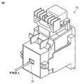
- FIG. 2 is a diagram showing the appearance of the contactor 15.
- FIG. 3 is a diagram schematically showing the internal configuration of the contactor 15.
- the contactor 15 has a movable iron core 31, a fixed iron core 32, a coil 34, a movable contact 36, and a fixed contact 38.
- the movable iron core 31, the fixed iron core 32, and the coil 34 form an electromagnet.
- the movable contact 36 is connected to the movable iron core 31.
- the contactor 15 is in the off state because the movable contact 36 and the fixed contact 38 are separated from each other.
- the movable iron core 31 When the coil 34 is excited by applying a voltage to the coil 34 from an operation circuit (not shown), the movable iron core 31 is attracted to the fixed iron core 32 side. At this time, the movable contact 36 connected to the movable iron core 31 moves toward the fixed contact 38. The contactor 15 is turned on when the movable contact 36 and the fixed contact 38 come into contact with each other.
- the contact of the contactor 15 has a main contact for turning on and off the load current and an auxiliary contact used for control.
- Auxiliary contacts include a-contact, which is a contact that turns on at the same time as the main contact is turned on, and b-contact, which is a contact that is turned on at the same time as the main contact is turned off.
- the contactor 15 further includes a manual switch 40 (hereinafter, also simply referred to as “switch 40”).
- the switch 40 is connected to the movable contact 36.
- the switch 40 is a push button type switch provided on the surface of the housing of the contactor 15.
- the switch 40 is configured so that it can be manually pressed from the outside of the housing. Specifically, when the switch 40 is pressed in the direction of the arrow in the drawing, a pressing force is applied from the switch 40 to the movable contact 36.
- the movable contact 36 moves toward the fixed contact 38 due to this pressing force, so that the movable contact 36 and the fixed contact 38 come into contact with each other, and as a result, the contactor 15 is turned on. That is, by pressing the switch 40, the contactor 15 can be turned on by force regardless of the excitation of the coil 34.
- This switch 40 is usually used when an operator manually turns on the contactor 15 during maintenance and inspection work of the contactor 15.
- the contact can be mechanically maintained in the closed state by operating the switch 40 connected to the contact.
- the uninterruptible power supply 100 is a mechanism for applying a pressing force to the switch 40 in order to automatically press the switch 40 without manually pressing it (hereinafter, "pressing pressure applying mechanism"). Also referred to as).
- the pressing force applying mechanism has a cylinder 22, a gas supply source 26, and a gas supply pipe 27.
- the cylinder 22 has a cylinder tube 22a, a piston 22b, and a piston rod 22c.
- the piston 22b is arranged inside the cylinder tube 22a.
- One end of the piston rod 22c is connected to the piston 22b, and the other end projects to the outside of the cylinder tube 22a and is connected to the switch 40 of the contactor 15.
- the gas supply source 26 stores a compressed inert gas (for example, nitrogen gas or argon gas).
- the gas supply source 26 is, for example, a gas cylinder.
- One end of the gas supply pipe 27 is connected to the gas supply source 26, and the other end is connected to the cylinder tube 22a.
- the gas pressure supplied from the gas supply source 26 passes through the gas supply pipe 27 and is introduced into the cylinder tube 22a.
- the piston 22b is pushed by the gas pressure introduced into the cylinder tube 22a, the pushing pressure is applied to the switch 40 by the piston rod 22c connected to the piston 22b as shown by an arrow in the figure.
- the contactor 15 is turned on when the movable contact 36 and the fixed contact 38 come into contact with each other in response to this pressing force.
- the pressing force applying mechanism a configuration for converting a gas pressure into a pressing force is illustrated, but a configuration for converting a pressure other than the gas pressure (for example, an oil pressure) into a pressing force may be used.
- the uninterruptible power supply 100 further includes a control circuit for controlling the operation of the pressing force applying mechanism.
- the gas supply pipe 27 is provided with a solenoid valve 24 for controlling the gas supply.
- the solenoid valve 24 is configured to be able to control the gas flow rate in the gas supply pipe 27 according to its opening degree. Specifically, by closing the solenoid valve 24, the supply of gas from the gas supply source 26 can be cut off. According to this, in the case where the solenoid valve 24 is normally closed and the contactor 15 is to be turned on, and a failure occurs in which the contactor 15 is not turned on, the cylinder is opened by opening the solenoid valve 24. The contactor 15 can be turned on by the pressing force generated by 22.
- the uninterruptible power supply 100 further includes a valve control unit 28 for controlling the opening and closing of the solenoid valve 24.
- the solenoid valve 24 and the valve control unit 28 correspond to an embodiment of a “control circuit” for controlling the operation / stop of the pressing force applying mechanism.
- the valve control unit 28 is configured to control the opening and closing of the solenoid valve 24 based on the information given from the control device 20.
- the information given from the control device 20 includes failure information, contact information, and other unit information.
- "Failure information” is information indicating that a failure has been detected in which the inverter power supply mode cannot be executed and the contactor 15 is not turned on.
- the control device 20 outputs an H level control signal to the contactor 15. If the contactor 15 is not detected to be turned on while the H level control signal is output, the control device 20 can detect the failure of the contactor 15. The on / off state of the contactor 15 can be detected based on the on / off state of the auxiliary contact that operates in conjunction with the main contact of the contactor 15.
- Contact information is information indicating an on / off state of the switch 14 and the contactor 15.
- the on / off of the switch 14 can be detected based on the on / off state of the auxiliary contact of the switch 14, similar to the on / off of the contactor 15.
- the switch 14 In the inverter power supply mode, the switch 14 is turned on and the contactor 15 is turned off.
- “Other unit information” is information indicating the operating state of another uninterruptible power supply (not shown) connected in parallel with the uninterruptible power supply 100 with respect to the load 18.
- the other unit information includes information on whether or not another uninterruptible power supply is supplying power to the load 18.
- the other unit information is based on the assumption that the uninterruptible power supply 100 is applied to a power failure system in which a plurality of uninterruptible power supplies are connected in parallel to the load 18. Therefore, if there is only one uninterruptible power supply connected to the load 18, information on other units can be omitted.
- the valve control unit 28 determines whether or not to operate the pressing application mechanism in order to turn on the contactor 15 based on the input information. Specifically, the valve control unit 28 determines that the pressing force applying mechanism is activated when the following conditions (1) to (3) are satisfied. (1) The inverter power supply mode cannot be executed and the contactor 15 is not turned on. A failure is detected. (2) Both the switch 14 and the contactor 15 are turned off. (3) Other uninterruptible power supply Does not supply power to the load 18 If the other unit information is omitted because another uninterruptible power supply is not connected to the load 18, the above (1) and (2) When the condition is satisfied, the valve control unit 28 determines that the pressing force applying mechanism is activated.
- the switch 14 is turned off in the condition (2). It can be rephrased as the condition.
- the condition that the switch 14 is off is that it is not necessary to turn on the contactor 15 when the switch 14 is on (in the inverter power supply mode), and the operation of the inverter 10 is stopped.
- the contactor 15 is turned on while the switch 14 is turned on, a part of the electric power supplied from the commercial AC power supply 1 to the load 18 via the contactor 15 flows into the inverter 10 via the switch 14. Because there is a possibility.
- the condition (3) is defined by turning on the contactor 15 while another uninterruptible power supply is supplying power to the load 18 between the other uninterruptible power supply and the uninterruptible power supply 100. This is because there is a possibility that a cross current may occur. For example, if the contactor 15 of the uninterruptible power supply 100 is turned on while another uninterruptible power supply is executing the inverter power supply mode, and a power failure occurs in the commercial AC power supply 1, the output terminal T2 of the uninterruptible power supply 100 Since the voltage of the inverter drops, current may flow from another uninterruptible power supply to the uninterruptible power supply 100.
- the valve control unit 28 controls to open the solenoid valve 24 when it determines that the pressing force applying mechanism is to be operated.
- the solenoid valve 24 is opened, gas is supplied from the gas supply source 26 to the cylinder 22 through the gas supply pipe 27.
- the pressing force is applied from the cylinder 22 to the switch 40, so that the contactor 15 is turned on.
- the contactor 15 is turned on, power is supplied from the commercial AC power source 1 to the load 18 via the contactor 15.
- the valve control unit 28 determines that the pressing force applying mechanism is not activated. In this case, the valve control unit 28 keeps the solenoid valve 24 in the closed state. Since gas is not supplied from the gas supply source 26 to the cylinder 22, no pressing force is applied to the switch 40, and as a result, the contactor 15 is not turned on.
- FIG. 4 is a diagram showing a configuration example of the valve control unit 28 shown in FIG.
- the valve control unit 28 has a logic circuit 280 and a drive unit 282.
- the logic circuit 280 calculates the logical product of the first input signal indicating failure information, the second input signal indicating contact information, and the third input signal indicating other machine information, and drives the signal indicating the calculation result. Output to unit 282.
- the first input signal indicates a logic "1” when the condition (1) above is satisfied, and indicates a logic "0” when the condition (1) is not satisfied.
- the second input signal is a signal that indicates logic "1” when the condition (2) is satisfied, and indicates logic "0” when the condition (2) is not satisfied.
- the third input signal is a signal indicating a logic "1” when the condition (3) is satisfied and a logic "0” when the condition (3) is not satisfied. The third input signal indicates the logic "1” even when another uninterruptible power supply is not connected to the load 18.
- the output signal of the logic circuit 280 indicates logic "1" when all the first to third input signals are logic “1", and at least one of the first to third input signals is logic "0". When is, the logic "0" is shown.
- the drive unit 282 drives the solenoid valve 24 so that the solenoid valve 24 opens when the output signal of the logic circuit 280 is logic "1". On the other hand, when the output signal of the logic circuit 280 is logic "0", the drive unit 282 drives the solenoid valve 24 so that the solenoid valve 24 is closed.
- valve control unit 28 is configured by using the logic circuit 280 which is an electric circuit, so that the pressing force application mechanism can be controlled with a simple and inexpensive configuration.
- the pressing force applying mechanism is operated to cause the contactor.
- the contactor 15 can be turned on by pressing the manual switch 40 provided on the 15. As a result, it is possible to avoid stopping the power supply to the load 18 due to the occurrence of a failure in which the contactor 15 is not turned on.
- the valve control unit 28 is composed of a logic circuit 280, which is an electric circuit, so that the control circuit can be made simple and inexpensive.
- the logic circuit 280 may be affected by the external environment such as electrical noise and temperature from the outside. This requires new components to protect the logic circuit 280 from electrical noise, temperature, and the like.
- FIG. 5 is a diagram showing another configuration example of the control circuit.
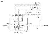
- the control circuit 30 includes a fluid logic element 29, branch pipes 27a, 27b, 27c, solenoid valves 24a, 24b, 24c and a drive unit 25.
- the gas supply pipe 27 is branched into a first branch pipe 27a, a second branch pipe 27b, and a third branch pipe 27c.
- a first solenoid valve 24a is provided in the first branch pipe 27a.
- a second solenoid valve 24b is provided on the second branch pipe 27b.
- a third solenoid valve 24c is provided in the third branch pipe 27c.
- the drive unit 25 includes a first drive unit 25a, a second drive unit 25b, and a third drive unit 25c.
- the first drive unit 25a receives the first input signal indicating failure information and controls the opening and closing of the first solenoid valve 24a.
- the first input signal indicates a logic "1" when the condition (1) is satisfied, and indicates a logic "0" when the condition (1) is not satisfied.
- the first drive unit 25a is so that the first solenoid valve 24a is closed when the first input signal is the logic "1" and the first solenoid valve 24a is opened when the first input signal is the logic "0". 1 Drive the solenoid valve 24a.
- the second drive unit 25b receives a second input signal indicating contact information and controls the opening and closing of the second solenoid valve 24b.
- the second input signal indicates a logic "1" when the condition (2) is satisfied, and indicates a logic "0" when the condition (2) is not satisfied.
- the second drive unit 25b closes the second solenoid valve 24b when the second input signal is the logic "1", and opens the second solenoid valve 24b when the second input signal is the logic "0". 2 Drives the solenoid valve 24b.
- the third drive unit 25c receives a third input signal indicating information on other units and controls the opening and closing of the third solenoid valve 24c.
- the third input signal indicates a logic "1” when the condition (3) is satisfied, and indicates a logic "0” when the condition (3) is not satisfied.
- the third input signal indicates the logic "1” even when another uninterruptible power supply is not connected to the load 18.
- the third drive unit 25c is so that the third solenoid valve 24c is closed when the third input signal is the logic "1" and the third solenoid valve 24c is opened when the third input signal is the logic "0". 3 Drives the solenoid valve 24c.
- FIG. 6 is a diagram showing a configuration example of the fluid logic element 29 shown in FIG.
- the fluid logic element 29 has an input port 290, control ports 296a, 296b, 296c, 295, a turbulent amplifier 294, and an output port 292.
- the input port 290 is connected to the gas supply pipe 27.
- the output port 292 is connected to the gas supply pipe 27.
- the first control port 296a is connected to the first branch pipe 27a.
- the second control port 296b is connected to the second branch pipe 27b.
- the third control port 296c is connected to the third branch pipe 27c.
- the turbulent amplifier 294 is connected between the input port 290 and the output port 292.
- Control ports 296a to 296c, 295 are connected to the turbulent amplifier 294.
- the turbulent flow amplifier 294 is configured to output the gas pressure P to the output port 292 when the gas pressure P is input to the input port 290.
- the control gas pressure acts on at least one of the control ports 296a, 296b, and 296c, the control gas pressure collides with the gas pressure P and an output is generated in the control port 295, so that the output is output to the output port 292. Does not occur.
- the fluid logic element 29 is gas when a control gas pressure is acting on at least one of the control ports 296a, 296b, 296c, that is, when at least one of the solenoid valves 24a, 24b, 24c is open. Do not allow gas to flow through the supply pipe 27. According to this, if at least one of the above conditions (1) to (3) is not satisfied, the gas pressure is not supplied from the gas supply source 26 to the cylinder 22.
- the fluid logic element 29 gas the gas supply pipe 27 when the control gas pressure is not acting on any of the control ports 296a and 296b, that is, when the solenoid valves 24a and 24b are both closed. Let the pressure flow. According to this, when all the above conditions (1) and (2) are satisfied, the gas pressure is supplied from the gas supply source 26 to the cylinder 22.
- the fluid logic element 29 is attached to the gas supply pipe 27 when the control gas pressure is acting on at least one of the control ports 296a and 296b, that is, when at least one of the solenoid valves 24a and 24b is open. Do not allow gas to flow. According to this, if at least one of the above conditions (1) and (2) is not satisfied, the gas pressure is not supplied from the gas supply source 26 to the cylinder 22.
Landscapes
- Engineering & Computer Science (AREA)
- General Engineering & Computer Science (AREA)
- Power Engineering (AREA)
- Physics & Mathematics (AREA)
- Electromagnetism (AREA)
- Mechanical Engineering (AREA)
- Business, Economics & Management (AREA)
- Emergency Management (AREA)
- Stand-By Power Supply Arrangements (AREA)
Abstract
Description
図1は、実施の形態による無停電電源装置の構成を示す回路ブロック図である。実施の形態による無停電電源装置100は、三相交流電力を受けて三相交流電力を出力するものであるが、図面および説明の簡単化のため、図1では、一相の交流電力に関連する部分のみが示されている。
図2は、コンタクタ15の外観を示す図である。図3は、コンタクタ15の内部構成を模式的に示す図である。
(1)インバータ給電モードが実行不能であり、かつ、コンタクタ15がオンされない故障が検出されていること
(2)スイッチ14およびコンタクタ15がともにオフされていること
(3)他の無停電電源装置が負荷18に電力を供給していないこと
なお、他の無停電電源装置が負荷18に接続されていないために他号機情報が省略されている場合には、上記(1)および(2)の条件が成立したときに、弁制御部28は、押圧力印加機構を作動させると判断する。
図4は、図1に示した弁制御部28の構成例を示す図である。
上述した実施の形態では、押圧力印加機構の作動/停止を制御するための制御回路に、電磁弁24および弁制御部28を用いる構成について説明した。この構成では、弁制御部28を電気回路である論理回路280で構成することにより、制御回路を簡易かつ低廉な構成とすることができる。その一方で、論理回路280が外部からの電気的ノイズおよび温度などの外部環境の影響を受ける可能性が懸念される。これには、電気的ノイズおよび温度などから論理回路280を保護するための部品が新たに必要となる。
図5は、制御回路の他の構成例を示す図である。図5を参照して、制御回路30は、流体論理素子29、分岐管27a,27b,27c、電磁弁24a,24b,24cおよび駆動部25を有する。
Claims (6)
- 交流電源からの交流電力を直流電力に変換するコンバータと、
前記コンバータで生成された直流電力または電力貯蔵装置の直流電力を交流電力に変換して負荷に供給するインバータと、
前記インバータと前記負荷との間に接続されるスイッチと、
前記交流電源および前記負荷の間に接続され、前記交流電源から前記負荷に交流電力を直接供給するバイパス給電時にオンされる電磁接触器と、
前記インバータから前記負荷に交流電力を供給するインバータ給電時、前記スイッチをオンし、かつ、前記電磁接触器をオフするとともに、前記インバータが故障した場合に、前記スイッチをオフし、かつ、前記電磁接触器をオンするように前記スイッチおよび前記電磁接触器を制御するように構成された制御装置とを備え、
前記電磁接触器は、前記制御装置からの制御信号に応じてコイルが励磁することにより接点が閉じてオンするように構成されるとともに、外部から押圧を受けて前記接点を閉じることが可能に構成された手動スイッチを有しており、
前記手動スイッチに対して押圧力を印加するように構成された押圧力印加機構と、
前記制御装置からの前記制御信号に従って前記電磁接触器をオンできない故障が発生した場合に、前記押圧力印加機構を作動する制御回路とをさらに備える、無停電電源装置。 - 前記制御回路は、第1から第3の条件が成立した場合に、前記押圧力印加機構を作動するように構成され、
前記第1の条件は、前記インバータ給電が実行不能であり、かつ、前記電磁接触器をオンできない故障が検出されていることであり、
前記第2の条件は、前記スイッチおよび前記電磁接触器がともにオフされていることであり、
前記第3の条件は、前記負荷に対して前記無停電電源装置と並列に他の無停電電源装置が接続されていないこと、または、前記他の無停電電源装置が接続されている場合において、前記他の無停電電源装置が前記負荷に電力を供給していないことである、請求項1に記載の無停電電源装置。 - 前記押圧力印加機構は、
ガス圧力を前記手動スイッチへの押圧力に変換するように構成されたシリンダと、
圧縮された不活性ガスを貯蔵するガス供給源と、
前記ガス供給源から前記シリンダにガス圧力を供給するためのガス供給管とを含み、
前記制御回路は、
前記ガス供給管に設置され、前記シリンダへのガス圧力の供給を制御する電磁弁と、
前記第1の条件を示す第1の入力信号、前記第2の条件を示す第2の入力信号および前記第3の条件を示す第3の入力信号を論理演算する論理回路と、
前記論理回路の出力信号に従って前記電磁弁を駆動する駆動部とを含む、請求項2に記載の無停電電源装置。 - 前記第1から第3の入力信号の各々は、対応する条件の成立時に論理「1」を示し、非成立時に論理「0」を示すように構成され、
前記論理回路は、前記第1から第3の入力信号がすべて論理「1」であるときに、前記電磁弁を開くための信号を前記駆動部へ出力する、請求項3に記載の無停電電源装置。 - 前記押圧力印加機構は、
ガス圧力を前記手動スイッチに対する押圧力に変換するように構成されたシリンダと、
圧縮された不活性ガスを貯蔵するガス供給源と、
前記ガス供給源から前記シリンダにガス圧力を供給するためのガス供給管とを含み、
前記制御回路は、
前記ガス供給管から分岐された第1から第3の分岐管と、
前記第1の分岐管に設置され、前記第1の条件を示す第1の入力信号を受けて駆動される第1の電磁弁と、
前記第2の分岐管に設置され、前記第2の条件を示す第2の入力信号を受けて駆動される第2の電磁弁と、
前記第3の分岐管に設置され、前記第3の条件を示す第3の入力信号を受けて駆動される第3の電磁弁と、
前記ガス供給管および前記第1から第3の分岐管に接続され、前記ガス供給管のガス圧力および前記第1から第3の分岐管のガス圧力の論理演算により前記シリンダにガス圧力を出力するように構成された流体論理素子とを含む、請求項2に記載の無停電電源装置。 - 前記第1から第3の入力信号の各々は、対応する条件の成立時に論理「1」を示し、非成立時に論理「0」を示すように構成され、
前記第1から第3の電磁弁はそれぞれ、前記第1から第3の入力信号が論理「1」であるときに閉じるように構成され、
前記流体論理素子は、前記第1から第3の分岐管のすべてからガス圧力が作用しない場合に、前記シリンダにガス圧力を出力する、請求項5に記載の無停電電源装置。
Priority Applications (5)
| Application Number | Priority Date | Filing Date | Title |
|---|---|---|---|
| KR1020217002049A KR102551412B1 (ko) | 2019-05-30 | 2019-05-30 | 무정전 전원 장치 |
| US17/256,870 US11444482B2 (en) | 2019-05-30 | 2019-05-30 | Uninterruptible power supply device |
| JP2019555053A JP6816308B1 (ja) | 2019-05-30 | 2019-05-30 | 無停電電源装置 |
| CN201980049982.4A CN112514201B (zh) | 2019-05-30 | 2019-05-30 | 不间断电源装置 |
| PCT/JP2019/021467 WO2020240761A1 (ja) | 2019-05-30 | 2019-05-30 | 無停電電源装置 |
Applications Claiming Priority (1)
| Application Number | Priority Date | Filing Date | Title |
|---|---|---|---|
| PCT/JP2019/021467 WO2020240761A1 (ja) | 2019-05-30 | 2019-05-30 | 無停電電源装置 |
Publications (1)
| Publication Number | Publication Date |
|---|---|
| WO2020240761A1 true WO2020240761A1 (ja) | 2020-12-03 |
Family
ID=73553144
Family Applications (1)
| Application Number | Title | Priority Date | Filing Date |
|---|---|---|---|
| PCT/JP2019/021467 Ceased WO2020240761A1 (ja) | 2019-05-30 | 2019-05-30 | 無停電電源装置 |
Country Status (5)
| Country | Link |
|---|---|
| US (1) | US11444482B2 (ja) |
| JP (1) | JP6816308B1 (ja) |
| KR (1) | KR102551412B1 (ja) |
| CN (1) | CN112514201B (ja) |
| WO (1) | WO2020240761A1 (ja) |
Families Citing this family (1)
| Publication number | Priority date | Publication date | Assignee | Title |
|---|---|---|---|---|
| JP7500879B1 (ja) * | 2022-11-24 | 2024-06-17 | 株式会社Tmeic | 電源装置 |
Citations (2)
| Publication number | Priority date | Publication date | Assignee | Title |
|---|---|---|---|---|
| JPS6271438A (ja) * | 1985-09-24 | 1987-04-02 | 株式会社明電舎 | 無停電電源装置 |
| JP2009112080A (ja) * | 2007-10-29 | 2009-05-21 | Nippon Telegr & Teleph Corp <Ntt> | 電源切替装置およびこれを用いた電源システム |
Family Cites Families (10)
| Publication number | Priority date | Publication date | Assignee | Title |
|---|---|---|---|---|
| JPH0783560B2 (ja) * | 1989-07-31 | 1995-09-06 | 三菱電機株式会社 | 無停電電源制御装置 |
| JP4111890B2 (ja) * | 2003-07-29 | 2008-07-02 | 三洋電機株式会社 | 無停電電源装置 |
| US9154925B2 (en) * | 2011-11-02 | 2015-10-06 | Qualcomm Incorporated | User experience enhancements for controlling a group communication |
| JP5917921B2 (ja) | 2012-01-18 | 2016-05-18 | 東芝三菱電機産業システム株式会社 | 無停電電源装置 |
| EP3160006B1 (en) | 2015-10-23 | 2019-04-17 | Siemens Aktiengesellschaft | Uninterruptible power supply |
| US10454772B2 (en) | 2015-10-30 | 2019-10-22 | Vapor IO Inc. | Compact uninteruptable power supply |
| US10756567B2 (en) * | 2015-11-27 | 2020-08-25 | Toshiba Mitsubishi-Electric Industrial Systems Corporation | Uninterruptible power supply device |
| JP6577355B2 (ja) * | 2015-12-15 | 2019-09-18 | 東芝三菱電機産業システム株式会社 | 電力変換システム |
| KR102324944B1 (ko) * | 2017-03-29 | 2021-11-10 | 엘에스일렉트릭(주) | 인버터 제어 장치 |
| KR101854089B1 (ko) | 2017-10-31 | 2018-06-08 | 이중오 | 전압상승 방지용 전기가변장치 및 그 제어 방법 |
-
2019
- 2019-05-30 WO PCT/JP2019/021467 patent/WO2020240761A1/ja not_active Ceased
- 2019-05-30 US US17/256,870 patent/US11444482B2/en active Active
- 2019-05-30 JP JP2019555053A patent/JP6816308B1/ja active Active
- 2019-05-30 CN CN201980049982.4A patent/CN112514201B/zh active Active
- 2019-05-30 KR KR1020217002049A patent/KR102551412B1/ko active Active
Patent Citations (2)
| Publication number | Priority date | Publication date | Assignee | Title |
|---|---|---|---|---|
| JPS6271438A (ja) * | 1985-09-24 | 1987-04-02 | 株式会社明電舎 | 無停電電源装置 |
| JP2009112080A (ja) * | 2007-10-29 | 2009-05-21 | Nippon Telegr & Teleph Corp <Ntt> | 電源切替装置およびこれを用いた電源システム |
Also Published As
| Publication number | Publication date |
|---|---|
| JP6816308B1 (ja) | 2021-01-20 |
| US20210257851A1 (en) | 2021-08-19 |
| CN112514201B (zh) | 2024-09-03 |
| KR20210021571A (ko) | 2021-02-26 |
| JPWO2020240761A1 (ja) | 2021-09-13 |
| US11444482B2 (en) | 2022-09-13 |
| CN112514201A (zh) | 2021-03-16 |
| KR102551412B1 (ko) | 2023-07-04 |
Similar Documents
| Publication | Publication Date | Title |
|---|---|---|
| CN109660180B (zh) | 电动机驱动装置 | |
| US9816576B2 (en) | Compact control device for failsafely controlling an electrical actuator | |
| JP2019146331A (ja) | 無停電電源システム及びその制御方法 | |
| JP5809029B2 (ja) | 無停電電源装置 | |
| JP6133827B2 (ja) | 電磁接触器の溶着検出機能を有するモータ駆動装置 | |
| JPWO2008132975A1 (ja) | 電力変換装置 | |
| JP2018164377A (ja) | 短絡故障検出機能を備えたコンバータ装置及びコンバータ装置の短絡故障検出方法 | |
| JP6816308B1 (ja) | 無停電電源装置 | |
| JP6390454B2 (ja) | 継電ユニット、および継電回路の制御方法 | |
| JP5444774B2 (ja) | 無停電電源システム | |
| US5549179A (en) | Cost effective control of the main switches of an elevator drive motor | |
| KR20250067074A (ko) | 지능형 바이패스 및 제거 가능 전력 스테이지를 갖는 정적 전송 스위치 | |
| JP2022143967A (ja) | 無停電電源装置 | |
| JP6435715B2 (ja) | 無停電電源装置 | |
| JP2012508552A (ja) | 供給ネットワークからの電力をコンシュマーネットワークに供給するためのデバイス | |
| TW201012029A (en) | Uninterruptible power supply device | |
| JP5130248B2 (ja) | 開閉器操作装置および3相用開閉器 | |
| JP6450508B2 (ja) | ヒステリシス電動機用ドライブ装置 | |
| JP4623221B2 (ja) | 電源回路 | |
| WO2022014139A1 (ja) | 空気作動弁の駆動機構 | |
| JP2994277B2 (ja) | 力率調整システム | |
| KR100931670B1 (ko) | 개폐기기 조작기구용 전자석 코일 감시회로 | |
| JP6072625B2 (ja) | エレベータ安全装置およびエレベータ制御方法 | |
| US20230107557A1 (en) | Method for monitoring an electrical switching arrangement | |
| JP4057941B2 (ja) | 電磁接触器の溶着及び押釦スイッチの故障検出装置 |
Legal Events
| Date | Code | Title | Description |
|---|---|---|---|
| ENP | Entry into the national phase |
Ref document number: 2019555053 Country of ref document: JP Kind code of ref document: A |
|
| 121 | Ep: the epo has been informed by wipo that ep was designated in this application |
Ref document number: 19930761 Country of ref document: EP Kind code of ref document: A1 |
|
| ENP | Entry into the national phase |
Ref document number: 20217002049 Country of ref document: KR Kind code of ref document: A |
|
| NENP | Non-entry into the national phase |
Ref country code: DE |
|
| 122 | Ep: pct application non-entry in european phase |
Ref document number: 19930761 Country of ref document: EP Kind code of ref document: A1 |