WO2020235534A1 - Matériau extérieur pour dispositif de stockage d'énergie, procédé de fabrication associé, dispositif de stockage d'énergie et film de polyamide - Google Patents
Matériau extérieur pour dispositif de stockage d'énergie, procédé de fabrication associé, dispositif de stockage d'énergie et film de polyamide Download PDFInfo
- Publication number
- WO2020235534A1 WO2020235534A1 PCT/JP2020/019675 JP2020019675W WO2020235534A1 WO 2020235534 A1 WO2020235534 A1 WO 2020235534A1 JP 2020019675 W JP2020019675 W JP 2020019675W WO 2020235534 A1 WO2020235534 A1 WO 2020235534A1
- Authority
- WO
- WIPO (PCT)
- Prior art keywords
- layer
- power storage
- storage device
- base material
- exterior material
- Prior art date
Links
- 239000000463 material Substances 0.000 title claims abstract description 338
- 238000003860 storage Methods 0.000 title claims abstract description 233
- 239000004952 Polyamide Substances 0.000 title claims abstract description 87
- 229920002647 polyamide Polymers 0.000 title claims abstract description 87
- 238000000034 method Methods 0.000 title claims description 102
- 238000004519 manufacturing process Methods 0.000 title claims description 15
- 229920005989 resin Polymers 0.000 claims abstract description 170
- 239000011347 resin Substances 0.000 claims abstract description 170
- 230000004888 barrier function Effects 0.000 claims abstract description 160
- 238000002425 crystallisation Methods 0.000 claims abstract description 53
- 230000008025 crystallization Effects 0.000 claims abstract description 53
- 238000005033 Fourier transform infrared spectroscopy Methods 0.000 claims abstract description 22
- 239000010410 layer Substances 0.000 claims description 515
- 239000012790 adhesive layer Substances 0.000 claims description 133
- 229920001187 thermosetting polymer Polymers 0.000 claims description 81
- 239000003792 electrolyte Substances 0.000 claims description 11
- 239000000758 substrate Substances 0.000 abstract 3
- 239000002585 base Substances 0.000 description 163
- 239000010408 film Substances 0.000 description 155
- -1 fluororesin Polymers 0.000 description 91
- 238000011282 treatment Methods 0.000 description 82
- 239000011888 foil Substances 0.000 description 71
- 239000000853 adhesive Substances 0.000 description 57
- 230000001070 adhesive effect Effects 0.000 description 57
- 229920000098 polyolefin Polymers 0.000 description 56
- 229910000838 Al alloy Inorganic materials 0.000 description 51
- 239000000314 lubricant Substances 0.000 description 37
- 229920006284 nylon film Polymers 0.000 description 36
- 239000002345 surface coating layer Substances 0.000 description 35
- 238000010030 laminating Methods 0.000 description 34
- 239000003795 chemical substances by application Substances 0.000 description 29
- 239000004814 polyurethane Substances 0.000 description 29
- 239000000126 substance Substances 0.000 description 28
- 238000006243 chemical reaction Methods 0.000 description 27
- 229920002635 polyurethane Polymers 0.000 description 26
- 150000001875 compounds Chemical class 0.000 description 25
- NBIIXXVUZAFLBC-UHFFFAOYSA-N Phosphoric acid Chemical compound OP(O)(O)=O NBIIXXVUZAFLBC-UHFFFAOYSA-N 0.000 description 24
- 239000004743 Polypropylene Substances 0.000 description 24
- 230000007797 corrosion Effects 0.000 description 24
- 238000005260 corrosion Methods 0.000 description 24
- 229920000642 polymer Polymers 0.000 description 24
- 229920001155 polypropylene Polymers 0.000 description 24
- 239000000654 additive Substances 0.000 description 22
- 238000000576 coating method Methods 0.000 description 22
- 238000007789 sealing Methods 0.000 description 22
- 239000010935 stainless steel Substances 0.000 description 21
- 229910001220 stainless steel Inorganic materials 0.000 description 21
- 238000005259 measurement Methods 0.000 description 20
- 229920000728 polyester Polymers 0.000 description 20
- 238000012360 testing method Methods 0.000 description 19
- 239000003822 epoxy resin Substances 0.000 description 18
- 229910052751 metal Inorganic materials 0.000 description 18
- 239000002184 metal Substances 0.000 description 18
- 229920000647 polyepoxide Polymers 0.000 description 18
- 238000010521 absorption reaction Methods 0.000 description 16
- 239000002253 acid Substances 0.000 description 16
- 239000004677 Nylon Substances 0.000 description 15
- 229920001778 nylon Polymers 0.000 description 15
- 125000003504 2-oxazolinyl group Chemical group O1C(=NCC1)* 0.000 description 14
- XEEYBQQBJWHFJM-UHFFFAOYSA-N Iron Chemical compound [Fe] XEEYBQQBJWHFJM-UHFFFAOYSA-N 0.000 description 14
- ZCDOYSPFYFSLEW-UHFFFAOYSA-N chromate(2-) Chemical compound [O-][Cr]([O-])(=O)=O ZCDOYSPFYFSLEW-UHFFFAOYSA-N 0.000 description 14
- 229920001577 copolymer Polymers 0.000 description 14
- 239000007788 liquid Substances 0.000 description 14
- 239000000049 pigment Substances 0.000 description 14
- NIXOWILDQLNWCW-UHFFFAOYSA-N 2-Propenoic acid Natural products OC(=O)C=C NIXOWILDQLNWCW-UHFFFAOYSA-N 0.000 description 13
- 230000000996 additive effect Effects 0.000 description 13
- 239000011651 chromium Substances 0.000 description 13
- 125000004122 cyclic group Chemical group 0.000 description 13
- 239000011342 resin composition Substances 0.000 description 13
- PXHVJJICTQNCMI-UHFFFAOYSA-N Nickel Chemical compound [Ni] PXHVJJICTQNCMI-UHFFFAOYSA-N 0.000 description 12
- 229910000147 aluminium phosphate Inorganic materials 0.000 description 12
- 229910052804 chromium Inorganic materials 0.000 description 12
- 239000005011 phenolic resin Substances 0.000 description 12
- 229920000139 polyethylene terephthalate Polymers 0.000 description 12
- 239000004925 Acrylic resin Substances 0.000 description 11
- VYZAMTAEIAYCRO-UHFFFAOYSA-N Chromium Chemical compound [Cr] VYZAMTAEIAYCRO-UHFFFAOYSA-N 0.000 description 11
- 229920000178 Acrylic resin Polymers 0.000 description 10
- 238000004566 IR spectroscopy Methods 0.000 description 10
- 230000032683 aging Effects 0.000 description 10
- 229910052782 aluminium Inorganic materials 0.000 description 10
- XAGFODPZIPBFFR-UHFFFAOYSA-N aluminium Chemical compound [Al] XAGFODPZIPBFFR-UHFFFAOYSA-N 0.000 description 10
- 150000001408 amides Chemical class 0.000 description 10
- 239000011248 coating agent Substances 0.000 description 10
- 239000013078 crystal Substances 0.000 description 10
- IQPQWNKOIGAROB-UHFFFAOYSA-N isocyanate group Chemical group [N-]=C=O IQPQWNKOIGAROB-UHFFFAOYSA-N 0.000 description 10
- 229910052757 nitrogen Inorganic materials 0.000 description 10
- 229920005862 polyol Polymers 0.000 description 10
- 229910021563 chromium fluoride Inorganic materials 0.000 description 9
- 239000003086 colorant Substances 0.000 description 9
- 239000000203 mixture Substances 0.000 description 9
- 239000002245 particle Substances 0.000 description 9
- JOYRKODLDBILNP-UHFFFAOYSA-N Ethyl urethane Chemical compound CCOC(N)=O JOYRKODLDBILNP-UHFFFAOYSA-N 0.000 description 8
- VYPSYNLAJGMNEJ-UHFFFAOYSA-N Silicium dioxide Chemical compound O=[Si]=O VYPSYNLAJGMNEJ-UHFFFAOYSA-N 0.000 description 8
- 238000000862 absorption spectrum Methods 0.000 description 8
- 125000002887 hydroxy group Chemical group [H]O* 0.000 description 8
- 239000002904 solvent Substances 0.000 description 8
- XLYOFNOQVPJJNP-UHFFFAOYSA-N water Substances O XLYOFNOQVPJJNP-UHFFFAOYSA-N 0.000 description 8
- OFOBLEOULBTSOW-UHFFFAOYSA-N Malonic acid Chemical compound OC(=O)CC(O)=O OFOBLEOULBTSOW-UHFFFAOYSA-N 0.000 description 7
- 125000003700 epoxy group Chemical group 0.000 description 7
- 230000001965 increasing effect Effects 0.000 description 7
- 229910052742 iron Inorganic materials 0.000 description 7
- 238000000465 moulding Methods 0.000 description 7
- 229920006267 polyester film Polymers 0.000 description 7
- RTZKZFJDLAIYFH-UHFFFAOYSA-N Diethyl ether Chemical compound CCOCC RTZKZFJDLAIYFH-UHFFFAOYSA-N 0.000 description 6
- 125000000217 alkyl group Chemical group 0.000 description 6
- TZCXTZWJZNENPQ-UHFFFAOYSA-L barium sulfate Chemical compound [Ba+2].[O-]S([O-])(=O)=O TZCXTZWJZNENPQ-UHFFFAOYSA-L 0.000 description 6
- 239000006229 carbon black Substances 0.000 description 6
- 238000004140 cleaning Methods 0.000 description 6
- 238000005238 degreasing Methods 0.000 description 6
- 238000010586 diagram Methods 0.000 description 6
- 230000002708 enhancing effect Effects 0.000 description 6
- 239000012948 isocyanate Substances 0.000 description 6
- 229910052759 nickel Inorganic materials 0.000 description 6
- 229910052761 rare earth metal Inorganic materials 0.000 description 6
- 150000003839 salts Chemical class 0.000 description 6
- 229920002803 thermoplastic polyurethane Polymers 0.000 description 6
- 238000005011 time of flight secondary ion mass spectroscopy Methods 0.000 description 6
- 238000002042 time-of-flight secondary ion mass spectrometry Methods 0.000 description 6
- SMZOUWXMTYCWNB-UHFFFAOYSA-N 2-(2-methoxy-5-methylphenyl)ethanamine Chemical compound COC1=CC=C(C)C=C1CCN SMZOUWXMTYCWNB-UHFFFAOYSA-N 0.000 description 5
- 229910019142 PO4 Inorganic materials 0.000 description 5
- 150000008064 anhydrides Chemical class 0.000 description 5
- 150000001732 carboxylic acid derivatives Chemical class 0.000 description 5
- 230000000052 comparative effect Effects 0.000 description 5
- 125000002768 hydroxyalkyl group Chemical group 0.000 description 5
- 239000000178 monomer Substances 0.000 description 5
- NBIIXXVUZAFLBC-UHFFFAOYSA-K phosphate Chemical compound [O-]P([O-])([O-])=O NBIIXXVUZAFLBC-UHFFFAOYSA-K 0.000 description 5
- 239000010452 phosphate Substances 0.000 description 5
- 229910052698 phosphorus Inorganic materials 0.000 description 5
- 229920001225 polyester resin Polymers 0.000 description 5
- 239000004645 polyester resin Substances 0.000 description 5
- 239000005020 polyethylene terephthalate Substances 0.000 description 5
- HBBGRARXTFLTSG-UHFFFAOYSA-N Lithium ion Chemical compound [Li+] HBBGRARXTFLTSG-UHFFFAOYSA-N 0.000 description 4
- ISWSIDIOOBJBQZ-UHFFFAOYSA-N Phenol Chemical compound OC1=CC=CC=C1 ISWSIDIOOBJBQZ-UHFFFAOYSA-N 0.000 description 4
- 229920002125 Sokalan® Polymers 0.000 description 4
- PPBRXRYQALVLMV-UHFFFAOYSA-N Styrene Chemical compound C=CC1=CC=CC=C1 PPBRXRYQALVLMV-UHFFFAOYSA-N 0.000 description 4
- GWEVSGVZZGPLCZ-UHFFFAOYSA-N Titan oxide Chemical compound O=[Ti]=O GWEVSGVZZGPLCZ-UHFFFAOYSA-N 0.000 description 4
- 238000005576 amination reaction Methods 0.000 description 4
- 229920006318 anionic polymer Polymers 0.000 description 4
- 239000002216 antistatic agent Substances 0.000 description 4
- 125000003118 aryl group Chemical group 0.000 description 4
- 239000003990 capacitor Substances 0.000 description 4
- 229920006317 cationic polymer Polymers 0.000 description 4
- 229910000420 cerium oxide Inorganic materials 0.000 description 4
- 238000005520 cutting process Methods 0.000 description 4
- 238000007598 dipping method Methods 0.000 description 4
- 230000000694 effects Effects 0.000 description 4
- 238000001125 extrusion Methods 0.000 description 4
- 238000007756 gravure coating Methods 0.000 description 4
- 238000010438 heat treatment Methods 0.000 description 4
- 230000010354 integration Effects 0.000 description 4
- 229910001416 lithium ion Inorganic materials 0.000 description 4
- FPYJFEHAWHCUMM-UHFFFAOYSA-N maleic anhydride Chemical compound O=C1OC(=O)C=C1 FPYJFEHAWHCUMM-UHFFFAOYSA-N 0.000 description 4
- 230000004048 modification Effects 0.000 description 4
- 238000012986 modification Methods 0.000 description 4
- BMMGVYCKOGBVEV-UHFFFAOYSA-N oxo(oxoceriooxy)cerium Chemical compound [Ce]=O.O=[Ce]=O BMMGVYCKOGBVEV-UHFFFAOYSA-N 0.000 description 4
- 239000004584 polyacrylic acid Substances 0.000 description 4
- 229920001707 polybutylene terephthalate Polymers 0.000 description 4
- 229920005906 polyester polyol Polymers 0.000 description 4
- 150000003077 polyols Chemical class 0.000 description 4
- 150000004671 saturated fatty acids Chemical class 0.000 description 4
- OGIDPMRJRNCKJF-UHFFFAOYSA-N titanium oxide Inorganic materials [Ti]=O OGIDPMRJRNCKJF-UHFFFAOYSA-N 0.000 description 4
- 150000004670 unsaturated fatty acids Chemical class 0.000 description 4
- 235000021122 unsaturated fatty acids Nutrition 0.000 description 4
- 238000007740 vapor deposition Methods 0.000 description 4
- OKTJSMMVPCPJKN-UHFFFAOYSA-N Carbon Chemical compound [C] OKTJSMMVPCPJKN-UHFFFAOYSA-N 0.000 description 3
- 229920000089 Cyclic olefin copolymer Polymers 0.000 description 3
- VGGSQFUCUMXWEO-UHFFFAOYSA-N Ethene Chemical compound C=C VGGSQFUCUMXWEO-UHFFFAOYSA-N 0.000 description 3
- 239000005977 Ethylene Substances 0.000 description 3
- WSFSSNUMVMOOMR-UHFFFAOYSA-N Formaldehyde Chemical compound O=C WSFSSNUMVMOOMR-UHFFFAOYSA-N 0.000 description 3
- 229920002292 Nylon 6 Polymers 0.000 description 3
- 229920002302 Nylon 6,6 Polymers 0.000 description 3
- 239000004721 Polyphenylene oxide Substances 0.000 description 3
- 239000004793 Polystyrene Substances 0.000 description 3
- 229920001328 Polyvinylidene chloride Polymers 0.000 description 3
- 239000002390 adhesive tape Substances 0.000 description 3
- 150000003863 ammonium salts Chemical class 0.000 description 3
- 239000003963 antioxidant agent Substances 0.000 description 3
- 229920001400 block copolymer Polymers 0.000 description 3
- 230000032798 delamination Effects 0.000 description 3
- 239000008151 electrolyte solution Substances 0.000 description 3
- 238000004146 energy storage Methods 0.000 description 3
- 239000010419 fine particle Substances 0.000 description 3
- 239000003063 flame retardant Substances 0.000 description 3
- 125000000524 functional group Chemical group 0.000 description 3
- VZCYOOQTPOCHFL-UPHRSURJSA-N maleic acid Chemical compound OC(=O)\C=C/C(O)=O VZCYOOQTPOCHFL-UPHRSURJSA-N 0.000 description 3
- 239000011976 maleic acid Substances 0.000 description 3
- 230000008018 melting Effects 0.000 description 3
- 238000002844 melting Methods 0.000 description 3
- 239000007769 metal material Substances 0.000 description 3
- 239000010445 mica Substances 0.000 description 3
- 229910052618 mica group Inorganic materials 0.000 description 3
- 229910052755 nonmetal Inorganic materials 0.000 description 3
- TWNQGVIAIRXVLR-UHFFFAOYSA-N oxo(oxoalumanyloxy)alumane Chemical compound O=[Al]O[Al]=O TWNQGVIAIRXVLR-UHFFFAOYSA-N 0.000 description 3
- 230000002093 peripheral effect Effects 0.000 description 3
- 150000002989 phenols Chemical class 0.000 description 3
- 239000011574 phosphorus Substances 0.000 description 3
- 229920006122 polyamide resin Polymers 0.000 description 3
- 229920000570 polyether Polymers 0.000 description 3
- 239000005056 polyisocyanate Substances 0.000 description 3
- 229920001228 polyisocyanate Polymers 0.000 description 3
- 229920005672 polyolefin resin Polymers 0.000 description 3
- 229920002223 polystyrene Polymers 0.000 description 3
- 229920005749 polyurethane resin Polymers 0.000 description 3
- 239000005033 polyvinylidene chloride Substances 0.000 description 3
- 230000008569 process Effects 0.000 description 3
- 229920005604 random copolymer Polymers 0.000 description 3
- 239000012508 resin bead Substances 0.000 description 3
- 239000002356 single layer Substances 0.000 description 3
- 159000000000 sodium salts Chemical class 0.000 description 3
- VZCYOOQTPOCHFL-UHFFFAOYSA-N trans-butenedioic acid Natural products OC(=O)C=CC(O)=O VZCYOOQTPOCHFL-UHFFFAOYSA-N 0.000 description 3
- 239000011701 zinc Substances 0.000 description 3
- FYGFTTWEWBXNMP-UHFFFAOYSA-N 10-amino-10-oxodecanoic acid Chemical class NC(=O)CCCCCCCCC(O)=O FYGFTTWEWBXNMP-UHFFFAOYSA-N 0.000 description 2
- RNFJDJUURJAICM-UHFFFAOYSA-N 2,2,4,4,6,6-hexaphenoxy-1,3,5-triaza-2$l^{5},4$l^{5},6$l^{5}-triphosphacyclohexa-1,3,5-triene Chemical compound N=1P(OC=2C=CC=CC=2)(OC=2C=CC=CC=2)=NP(OC=2C=CC=CC=2)(OC=2C=CC=CC=2)=NP=1(OC=1C=CC=CC=1)OC1=CC=CC=C1 RNFJDJUURJAICM-UHFFFAOYSA-N 0.000 description 2
- KXGFMDJXCMQABM-UHFFFAOYSA-N 2-methoxy-6-methylphenol Chemical compound [CH]OC1=CC=CC([CH])=C1O KXGFMDJXCMQABM-UHFFFAOYSA-N 0.000 description 2
- UPMLOUAZCHDJJD-UHFFFAOYSA-N 4,4'-Diphenylmethane Diisocyanate Chemical compound C1=CC(N=C=O)=CC=C1CC1=CC=C(N=C=O)C=C1 UPMLOUAZCHDJJD-UHFFFAOYSA-N 0.000 description 2
- LCFVJGUPQDGYKZ-UHFFFAOYSA-N Bisphenol A diglycidyl ether Chemical compound C=1C=C(OCC2OC2)C=CC=1C(C)(C)C(C=C1)=CC=C1OCC1CO1 LCFVJGUPQDGYKZ-UHFFFAOYSA-N 0.000 description 2
- KAKZBPTYRLMSJV-UHFFFAOYSA-N Butadiene Chemical compound C=CC=C KAKZBPTYRLMSJV-UHFFFAOYSA-N 0.000 description 2
- VTYYLEPIZMXCLO-UHFFFAOYSA-L Calcium carbonate Chemical compound [Ca+2].[O-]C([O-])=O VTYYLEPIZMXCLO-UHFFFAOYSA-L 0.000 description 2
- 239000004215 Carbon black (E152) Substances 0.000 description 2
- RYGMFSIKBFXOCR-UHFFFAOYSA-N Copper Chemical compound [Cu] RYGMFSIKBFXOCR-UHFFFAOYSA-N 0.000 description 2
- KRHYYFGTRYWZRS-UHFFFAOYSA-M Fluoride anion Chemical compound [F-] KRHYYFGTRYWZRS-UHFFFAOYSA-M 0.000 description 2
- YCKRFDGAMUMZLT-UHFFFAOYSA-N Fluorine atom Chemical compound [F] YCKRFDGAMUMZLT-UHFFFAOYSA-N 0.000 description 2
- PEDCQBHIVMGVHV-UHFFFAOYSA-N Glycerine Chemical compound OCC(O)CO PEDCQBHIVMGVHV-UHFFFAOYSA-N 0.000 description 2
- 239000005057 Hexamethylene diisocyanate Substances 0.000 description 2
- UFHFLCQGNIYNRP-UHFFFAOYSA-N Hydrogen Chemical compound [H][H] UFHFLCQGNIYNRP-UHFFFAOYSA-N 0.000 description 2
- RRHGJUQNOFWUDK-UHFFFAOYSA-N Isoprene Chemical compound CC(=C)C=C RRHGJUQNOFWUDK-UHFFFAOYSA-N 0.000 description 2
- CERQOIWHTDAKMF-UHFFFAOYSA-N Methacrylic acid Chemical compound CC(=C)C(O)=O CERQOIWHTDAKMF-UHFFFAOYSA-N 0.000 description 2
- AFCARXCZXQIEQB-UHFFFAOYSA-N N-[3-oxo-3-(2,4,6,7-tetrahydrotriazolo[4,5-c]pyridin-5-yl)propyl]-2-[[3-(trifluoromethoxy)phenyl]methylamino]pyrimidine-5-carboxamide Chemical compound O=C(CCNC(=O)C=1C=NC(=NC=1)NCC1=CC(=CC=C1)OC(F)(F)F)N1CC2=C(CC1)NN=N2 AFCARXCZXQIEQB-UHFFFAOYSA-N 0.000 description 2
- 238000005481 NMR spectroscopy Methods 0.000 description 2
- 239000004698 Polyethylene Substances 0.000 description 2
- 229920002873 Polyethylenimine Polymers 0.000 description 2
- XUIMIQQOPSSXEZ-UHFFFAOYSA-N Silicon Chemical compound [Si] XUIMIQQOPSSXEZ-UHFFFAOYSA-N 0.000 description 2
- 238000004833 X-ray photoelectron spectroscopy Methods 0.000 description 2
- HCHKCACWOHOZIP-UHFFFAOYSA-N Zinc Chemical compound [Zn] HCHKCACWOHOZIP-UHFFFAOYSA-N 0.000 description 2
- XLOMVQKBTHCTTD-UHFFFAOYSA-N Zinc monoxide Chemical compound [Zn]=O XLOMVQKBTHCTTD-UHFFFAOYSA-N 0.000 description 2
- 230000004913 activation Effects 0.000 description 2
- 125000001931 aliphatic group Chemical group 0.000 description 2
- 239000003513 alkali Substances 0.000 description 2
- 150000001336 alkenes Chemical class 0.000 description 2
- 238000004458 analytical method Methods 0.000 description 2
- 238000007743 anodising Methods 0.000 description 2
- 230000003078 antioxidant effect Effects 0.000 description 2
- 229910000963 austenitic stainless steel Inorganic materials 0.000 description 2
- 230000005540 biological transmission Effects 0.000 description 2
- OSGAYBCDTDRGGQ-UHFFFAOYSA-L calcium sulfate Chemical compound [Ca+2].[O-]S([O-])(=O)=O OSGAYBCDTDRGGQ-UHFFFAOYSA-L 0.000 description 2
- 125000004432 carbon atom Chemical group C* 0.000 description 2
- 125000003178 carboxy group Chemical group [H]OC(*)=O 0.000 description 2
- 229920002678 cellulose Polymers 0.000 description 2
- UUAGAQFQZIEFAH-UHFFFAOYSA-N chlorotrifluoroethylene Chemical group FC(F)=C(F)Cl UUAGAQFQZIEFAH-UHFFFAOYSA-N 0.000 description 2
- PHFQLYPOURZARY-UHFFFAOYSA-N chromium trinitrate Chemical compound [Cr+3].[O-][N+]([O-])=O.[O-][N+]([O-])=O.[O-][N+]([O-])=O PHFQLYPOURZARY-UHFFFAOYSA-N 0.000 description 2
- 239000000470 constituent Substances 0.000 description 2
- 229910052802 copper Inorganic materials 0.000 description 2
- 239000010949 copper Substances 0.000 description 2
- 238000003851 corona treatment Methods 0.000 description 2
- 238000005536 corrosion prevention Methods 0.000 description 2
- 239000003431 cross linking reagent Substances 0.000 description 2
- MGNZXYYWBUKAII-UHFFFAOYSA-N cyclohexa-1,3-diene Chemical compound C1CC=CC=C1 MGNZXYYWBUKAII-UHFFFAOYSA-N 0.000 description 2
- ZSWFCLXCOIISFI-UHFFFAOYSA-N cyclopentadiene Chemical compound C1C=CC=C1 ZSWFCLXCOIISFI-UHFFFAOYSA-N 0.000 description 2
- 238000004925 denaturation Methods 0.000 description 2
- 230000036425 denaturation Effects 0.000 description 2
- 235000014113 dietary fatty acids Nutrition 0.000 description 2
- GYZLOYUZLJXAJU-UHFFFAOYSA-N diglycidyl ether Chemical class C1OC1COCC1CO1 GYZLOYUZLJXAJU-UHFFFAOYSA-N 0.000 description 2
- 239000006185 dispersion Substances 0.000 description 2
- 239000002612 dispersion medium Substances 0.000 description 2
- 238000009826 distribution Methods 0.000 description 2
- 239000000975 dye Substances 0.000 description 2
- UAUDZVJPLUQNMU-KTKRTIGZSA-N erucamide Chemical class CCCCCCCC\C=C/CCCCCCCCCCCC(N)=O UAUDZVJPLUQNMU-KTKRTIGZSA-N 0.000 description 2
- MVLVMROFTAUDAG-UHFFFAOYSA-N ethyl octadecanoate Chemical compound CCCCCCCCCCCCCCCCCC(=O)OCC MVLVMROFTAUDAG-UHFFFAOYSA-N 0.000 description 2
- 238000007765 extrusion coating Methods 0.000 description 2
- 239000000194 fatty acid Substances 0.000 description 2
- 229930195729 fatty acid Natural products 0.000 description 2
- 229910052731 fluorine Inorganic materials 0.000 description 2
- 239000011737 fluorine Substances 0.000 description 2
- 125000003709 fluoroalkyl group Chemical group 0.000 description 2
- 238000002290 gas chromatography-mass spectrometry Methods 0.000 description 2
- 238000005227 gel permeation chromatography Methods 0.000 description 2
- 125000000623 heterocyclic group Chemical group 0.000 description 2
- RRAMGCGOFNQTLD-UHFFFAOYSA-N hexamethylene diisocyanate Chemical compound O=C=NCCCCCCN=C=O RRAMGCGOFNQTLD-UHFFFAOYSA-N 0.000 description 2
- 125000004836 hexamethylene group Chemical group [H]C([H])([*:2])C([H])([H])C([H])([H])C([H])([H])C([H])([H])C([H])([H])[*:1] 0.000 description 2
- 229930195733 hydrocarbon Natural products 0.000 description 2
- 150000002430 hydrocarbons Chemical class 0.000 description 2
- 229910052739 hydrogen Inorganic materials 0.000 description 2
- 239000001257 hydrogen Substances 0.000 description 2
- 125000004435 hydrogen atom Chemical group [H]* 0.000 description 2
- 230000006872 improvement Effects 0.000 description 2
- 230000008595 infiltration Effects 0.000 description 2
- 238000001764 infiltration Methods 0.000 description 2
- 229910052809 inorganic oxide Inorganic materials 0.000 description 2
- 150000002500 ions Chemical group 0.000 description 2
- 150000002513 isocyanates Chemical class 0.000 description 2
- MRELNEQAGSRDBK-UHFFFAOYSA-N lanthanum(3+);oxygen(2-) Chemical compound [O-2].[O-2].[O-2].[La+3].[La+3] MRELNEQAGSRDBK-UHFFFAOYSA-N 0.000 description 2
- 239000004611 light stabiliser Substances 0.000 description 2
- HQKMJHAJHXVSDF-UHFFFAOYSA-L magnesium stearate Chemical compound [Mg+2].CCCCCCCCCCCCCCCCCC([O-])=O.CCCCCCCCCCCCCCCCCC([O-])=O HQKMJHAJHXVSDF-UHFFFAOYSA-L 0.000 description 2
- 150000002739 metals Chemical class 0.000 description 2
- XMYQHJDBLRZMLW-UHFFFAOYSA-N methanolamine Chemical class NCO XMYQHJDBLRZMLW-UHFFFAOYSA-N 0.000 description 2
- FTQWRYSLUYAIRQ-UHFFFAOYSA-N n-[(octadecanoylamino)methyl]octadecanamide Chemical compound CCCCCCCCCCCCCCCCCC(=O)NCNC(=O)CCCCCCCCCCCCCCCCC FTQWRYSLUYAIRQ-UHFFFAOYSA-N 0.000 description 2
- PLDDOISOJJCEMH-UHFFFAOYSA-N neodymium(3+);oxygen(2-) Chemical compound [O-2].[O-2].[O-2].[Nd+3].[Nd+3] PLDDOISOJJCEMH-UHFFFAOYSA-N 0.000 description 2
- JFNLZVQOOSMTJK-KNVOCYPGSA-N norbornene Chemical compound C1[C@@H]2CC[C@H]1C=C2 JFNLZVQOOSMTJK-KNVOCYPGSA-N 0.000 description 2
- JRZJOMJEPLMPRA-UHFFFAOYSA-N olefin Natural products CCCCCCCC=C JRZJOMJEPLMPRA-UHFFFAOYSA-N 0.000 description 2
- 239000012860 organic pigment Substances 0.000 description 2
- 229910052760 oxygen Inorganic materials 0.000 description 2
- 229920001568 phenolic resin Polymers 0.000 description 2
- 229920003207 poly(ethylene-2,6-naphthalate) Polymers 0.000 description 2
- 229920000573 polyethylene Polymers 0.000 description 2
- 239000011112 polyethylene naphthalate Substances 0.000 description 2
- 150000003141 primary amines Chemical class 0.000 description 2
- 230000001737 promoting effect Effects 0.000 description 2
- QQONPFPTGQHPMA-UHFFFAOYSA-N propylene Natural products CC=C QQONPFPTGQHPMA-UHFFFAOYSA-N 0.000 description 2
- 125000004805 propylene group Chemical group [H]C([H])([H])C([H])([*:1])C([H])([H])[*:2] 0.000 description 2
- 229910052710 silicon Inorganic materials 0.000 description 2
- 239000010703 silicon Substances 0.000 description 2
- 239000000377 silicon dioxide Substances 0.000 description 2
- NDVLTYZPCACLMA-UHFFFAOYSA-N silver oxide Chemical compound [O-2].[Ag+].[Ag+] NDVLTYZPCACLMA-UHFFFAOYSA-N 0.000 description 2
- 239000000243 solution Substances 0.000 description 2
- 229920003002 synthetic resin Polymers 0.000 description 2
- 239000000057 synthetic resin Substances 0.000 description 2
- 239000010409 thin film Substances 0.000 description 2
- DVKJHBMWWAPEIU-UHFFFAOYSA-N toluene 2,4-diisocyanate Chemical compound CC1=CC=C(N=C=O)C=C1N=C=O DVKJHBMWWAPEIU-UHFFFAOYSA-N 0.000 description 2
- LWIHDJKSTIGBAC-UHFFFAOYSA-K tripotassium phosphate Chemical compound [K+].[K+].[K+].[O-]P([O-])([O-])=O LWIHDJKSTIGBAC-UHFFFAOYSA-K 0.000 description 2
- 239000013585 weight reducing agent Substances 0.000 description 2
- 229910052725 zinc Inorganic materials 0.000 description 2
- 239000004711 α-olefin Substances 0.000 description 2
- CPUBMKFFRRFXIP-YPAXQUSRSA-N (9z,33z)-dotetraconta-9,33-dienediamide Chemical compound NC(=O)CCCCCCC\C=C/CCCCCCCCCCCCCCCCCCCCCC\C=C/CCCCCCCC(N)=O CPUBMKFFRRFXIP-YPAXQUSRSA-N 0.000 description 1
- KVPQFVHBQUTWLQ-CVBJKYQLSA-N (z)-docos-13-enamide;ethene Chemical compound C=C.CCCCCCCC\C=C/CCCCCCCCCCCC(N)=O.CCCCCCCC\C=C/CCCCCCCCCCCC(N)=O KVPQFVHBQUTWLQ-CVBJKYQLSA-N 0.000 description 1
- VZGOTNLOZGRSJA-ZZEZOPTASA-N (z)-n-octadecyloctadec-9-enamide Chemical compound CCCCCCCCCCCCCCCCCCNC(=O)CCCCCCC\C=C/CCCCCCCC VZGOTNLOZGRSJA-ZZEZOPTASA-N 0.000 description 1
- 125000004066 1-hydroxyethyl group Chemical group [H]OC([H])([*])C([H])([H])[H] 0.000 description 1
- HECLRDQVFMWTQS-RGOKHQFPSA-N 1755-01-7 Chemical compound C1[C@H]2[C@@H]3CC=C[C@@H]3[C@@H]1C=C2 HECLRDQVFMWTQS-RGOKHQFPSA-N 0.000 description 1
- RDYWHMBYTHVOKZ-UHFFFAOYSA-N 18-hydroxyoctadecanamide Chemical compound NC(=O)CCCCCCCCCCCCCCCCCO RDYWHMBYTHVOKZ-UHFFFAOYSA-N 0.000 description 1
- XHSVWKJCURCWFU-UHFFFAOYSA-N 19-[3-(19-amino-19-oxononadecyl)phenyl]nonadecanamide Chemical compound NC(=O)CCCCCCCCCCCCCCCCCCC1=CC=CC(CCCCCCCCCCCCCCCCCCC(N)=O)=C1 XHSVWKJCURCWFU-UHFFFAOYSA-N 0.000 description 1
- VESQWGARFWAICR-UHFFFAOYSA-N 2,2-dihydroxyoctadecanamide;ethene Chemical compound C=C.CCCCCCCCCCCCCCCCC(O)(O)C(N)=O VESQWGARFWAICR-UHFFFAOYSA-N 0.000 description 1
- JAHNSTQSQJOJLO-UHFFFAOYSA-N 2-(3-fluorophenyl)-1h-imidazole Chemical compound FC1=CC=CC(C=2NC=CN=2)=C1 JAHNSTQSQJOJLO-UHFFFAOYSA-N 0.000 description 1
- KHTJRKQAETUUQH-UHFFFAOYSA-N 2-(hydroxymethyl)octadecanamide Chemical compound CCCCCCCCCCCCCCCCC(CO)C(N)=O KHTJRKQAETUUQH-UHFFFAOYSA-N 0.000 description 1
- 125000000954 2-hydroxyethyl group Chemical group [H]C([*])([H])C([H])([H])O[H] 0.000 description 1
- 125000003903 2-propenyl group Chemical group [H]C([*])([H])C([H])=C([H])[H] 0.000 description 1
- FVUKYCZRWSQGAS-UHFFFAOYSA-N 3-carbamoylbenzoic acid Chemical compound NC(=O)C1=CC=CC(C(O)=O)=C1 FVUKYCZRWSQGAS-UHFFFAOYSA-N 0.000 description 1
- OFNISBHGPNMTMS-UHFFFAOYSA-N 3-methylideneoxolane-2,5-dione Chemical compound C=C1CC(=O)OC1=O OFNISBHGPNMTMS-UHFFFAOYSA-N 0.000 description 1
- LLLVZDVNHNWSDS-UHFFFAOYSA-N 4-methylidene-3,5-dioxabicyclo[5.2.2]undeca-1(9),7,10-triene-2,6-dione Chemical compound C1(C2=CC=C(C(=O)OC(=C)O1)C=C2)=O LLLVZDVNHNWSDS-UHFFFAOYSA-N 0.000 description 1
- GZVHEAJQGPRDLQ-UHFFFAOYSA-N 6-phenyl-1,3,5-triazine-2,4-diamine Chemical compound NC1=NC(N)=NC(C=2C=CC=CC=2)=N1 GZVHEAJQGPRDLQ-UHFFFAOYSA-N 0.000 description 1
- 241000251468 Actinopterygii Species 0.000 description 1
- GVNWZKBFMFUVNX-UHFFFAOYSA-N Adipamide Chemical compound NC(=O)CCCCC(N)=O GVNWZKBFMFUVNX-UHFFFAOYSA-N 0.000 description 1
- 239000004953 Aliphatic polyamide Substances 0.000 description 1
- 239000005995 Aluminium silicate Substances 0.000 description 1
- 239000004254 Ammonium phosphate Substances 0.000 description 1
- 229910052684 Cerium Inorganic materials 0.000 description 1
- 241000252505 Characidae Species 0.000 description 1
- 229910021555 Chromium Chloride Inorganic materials 0.000 description 1
- LFQSCWFLJHTTHZ-UHFFFAOYSA-N Ethanol Chemical compound CCO LFQSCWFLJHTTHZ-UHFFFAOYSA-N 0.000 description 1
- 229920000219 Ethylene vinyl alcohol Polymers 0.000 description 1
- 229910001200 Ferrotitanium Inorganic materials 0.000 description 1
- KRHYYFGTRYWZRS-UHFFFAOYSA-N Fluorane Chemical compound F KRHYYFGTRYWZRS-UHFFFAOYSA-N 0.000 description 1
- JHWNWJKBPDFINM-UHFFFAOYSA-N Laurolactam Chemical compound O=C1CCCCCCCCCCCN1 JHWNWJKBPDFINM-UHFFFAOYSA-N 0.000 description 1
- FYYHWMGAXLPEAU-UHFFFAOYSA-N Magnesium Chemical compound [Mg] FYYHWMGAXLPEAU-UHFFFAOYSA-N 0.000 description 1
- PWHULOQIROXLJO-UHFFFAOYSA-N Manganese Chemical compound [Mn] PWHULOQIROXLJO-UHFFFAOYSA-N 0.000 description 1
- 229920000877 Melamine resin Polymers 0.000 description 1
- 239000004640 Melamine resin Substances 0.000 description 1
- NIPNSKYNPDTRPC-UHFFFAOYSA-N N-[2-oxo-2-(2,4,6,7-tetrahydrotriazolo[4,5-c]pyridin-5-yl)ethyl]-2-[[3-(trifluoromethoxy)phenyl]methylamino]pyrimidine-5-carboxamide Chemical compound O=C(CNC(=O)C=1C=NC(=NC=1)NCC1=CC(=CC=C1)OC(F)(F)F)N1CC2=C(CC1)NN=N2 NIPNSKYNPDTRPC-UHFFFAOYSA-N 0.000 description 1
- TXQHYIKVGQIJAM-UHFFFAOYSA-N N=C=O.N=C=O.CCCCC Chemical compound N=C=O.N=C=O.CCCCC TXQHYIKVGQIJAM-UHFFFAOYSA-N 0.000 description 1
- 229910000990 Ni alloy Inorganic materials 0.000 description 1
- 229920000459 Nitrile rubber Polymers 0.000 description 1
- 229920000299 Nylon 12 Polymers 0.000 description 1
- 229920003189 Nylon 4,6 Polymers 0.000 description 1
- CBENFWSGALASAD-UHFFFAOYSA-N Ozone Chemical compound [O-][O+]=O CBENFWSGALASAD-UHFFFAOYSA-N 0.000 description 1
- OAICVXFJPJFONN-UHFFFAOYSA-N Phosphorus Chemical compound [P] OAICVXFJPJFONN-UHFFFAOYSA-N 0.000 description 1
- 229920002845 Poly(methacrylic acid) Polymers 0.000 description 1
- 239000004642 Polyimide Substances 0.000 description 1
- NRCMAYZCPIVABH-UHFFFAOYSA-N Quinacridone Chemical compound N1C2=CC=CC=C2C(=O)C2=C1C=C1C(=O)C3=CC=CC=C3NC1=C2 NRCMAYZCPIVABH-UHFFFAOYSA-N 0.000 description 1
- 238000001069 Raman spectroscopy Methods 0.000 description 1
- 239000006087 Silane Coupling Agent Substances 0.000 description 1
- 229910000831 Steel Inorganic materials 0.000 description 1
- WGLPBDUCMAPZCE-UHFFFAOYSA-N Trioxochromium Chemical compound O=[Cr](=O)=O WGLPBDUCMAPZCE-UHFFFAOYSA-N 0.000 description 1
- 229920001807 Urea-formaldehyde Polymers 0.000 description 1
- 229920001986 Vinylidene chloride-vinyl chloride copolymer Polymers 0.000 description 1
- 238000000441 X-ray spectroscopy Methods 0.000 description 1
- 229910021536 Zeolite Inorganic materials 0.000 description 1
- ZZFYMXKVLJANAK-UHFFFAOYSA-N [Cr+3].[Cr+3].[O-][Cr](=O)(=O)O[Cr]([O-])(=O)=O.[O-][Cr](=O)(=O)O[Cr]([O-])(=O)=O.[O-][Cr](=O)(=O)O[Cr]([O-])(=O)=O Chemical compound [Cr+3].[Cr+3].[O-][Cr](=O)(=O)O[Cr]([O-])(=O)=O.[O-][Cr](=O)(=O)O[Cr]([O-])(=O)=O.[O-][Cr](=O)(=O)O[Cr]([O-])(=O)=O ZZFYMXKVLJANAK-UHFFFAOYSA-N 0.000 description 1
- 150000008065 acid anhydrides Chemical class 0.000 description 1
- WNLRTRBMVRJNCN-UHFFFAOYSA-L adipate(2-) Chemical compound [O-]C(=O)CCCCC([O-])=O WNLRTRBMVRJNCN-UHFFFAOYSA-L 0.000 description 1
- RSYUFYQTACJFML-DZGCQCFKSA-N afzelechin Chemical compound C1([C@H]2OC3=CC(O)=CC(O)=C3C[C@@H]2O)=CC=C(O)C=C1 RSYUFYQTACJFML-DZGCQCFKSA-N 0.000 description 1
- 239000005456 alcohol based solvent Substances 0.000 description 1
- 229920003231 aliphatic polyamide Polymers 0.000 description 1
- WNROFYMDJYEPJX-UHFFFAOYSA-K aluminium hydroxide Chemical compound [OH-].[OH-].[OH-].[Al+3] WNROFYMDJYEPJX-UHFFFAOYSA-K 0.000 description 1
- PNEYBMLMFCGWSK-UHFFFAOYSA-N aluminium oxide Inorganic materials [O-2].[O-2].[O-2].[Al+3].[Al+3] PNEYBMLMFCGWSK-UHFFFAOYSA-N 0.000 description 1
- 235000012211 aluminium silicate Nutrition 0.000 description 1
- 150000001412 amines Chemical class 0.000 description 1
- 229920003180 amino resin Polymers 0.000 description 1
- 229910000148 ammonium phosphate Inorganic materials 0.000 description 1
- 235000019289 ammonium phosphates Nutrition 0.000 description 1
- 238000000137 annealing Methods 0.000 description 1
- 229910000410 antimony oxide Inorganic materials 0.000 description 1
- 239000012298 atmosphere Substances 0.000 description 1
- 229910001566 austenite Inorganic materials 0.000 description 1
- 238000007611 bar coating method Methods 0.000 description 1
- MYONAGGJKCJOBT-UHFFFAOYSA-N benzimidazol-2-one Chemical compound C1=CC=CC2=NC(=O)N=C21 MYONAGGJKCJOBT-UHFFFAOYSA-N 0.000 description 1
- 125000001797 benzyl group Chemical group [H]C1=C([H])C([H])=C(C([H])=C1[H])C([H])([H])* 0.000 description 1
- 230000015572 biosynthetic process Effects 0.000 description 1
- 239000002981 blocking agent Substances 0.000 description 1
- 229910001593 boehmite Inorganic materials 0.000 description 1
- 229910052793 cadmium Inorganic materials 0.000 description 1
- BDOSMKKIYDKNTQ-UHFFFAOYSA-N cadmium atom Chemical compound [Cd] BDOSMKKIYDKNTQ-UHFFFAOYSA-N 0.000 description 1
- 239000001030 cadmium pigment Substances 0.000 description 1
- 239000004301 calcium benzoate Substances 0.000 description 1
- 235000010237 calcium benzoate Nutrition 0.000 description 1
- 229910000019 calcium carbonate Inorganic materials 0.000 description 1
- QXDMQSPYEZFLGF-UHFFFAOYSA-L calcium oxalate Chemical compound [Ca+2].[O-]C(=O)C([O-])=O QXDMQSPYEZFLGF-UHFFFAOYSA-L 0.000 description 1
- 239000000378 calcium silicate Substances 0.000 description 1
- 229910052918 calcium silicate Inorganic materials 0.000 description 1
- HZQXCUSDXIKLGS-UHFFFAOYSA-L calcium;dibenzoate;trihydrate Chemical compound O.O.O.[Ca+2].[O-]C(=O)C1=CC=CC=C1.[O-]C(=O)C1=CC=CC=C1 HZQXCUSDXIKLGS-UHFFFAOYSA-L 0.000 description 1
- OYACROKNLOSFPA-UHFFFAOYSA-N calcium;dioxido(oxo)silane Chemical compound [Ca+2].[O-][Si]([O-])=O OYACROKNLOSFPA-UHFFFAOYSA-N 0.000 description 1
- 229910052799 carbon Inorganic materials 0.000 description 1
- 239000002041 carbon nanotube Substances 0.000 description 1
- 229910021393 carbon nanotube Inorganic materials 0.000 description 1
- 150000001735 carboxylic acids Chemical class 0.000 description 1
- 150000001768 cations Chemical class 0.000 description 1
- 239000001913 cellulose Substances 0.000 description 1
- 238000006757 chemical reactions by type Methods 0.000 description 1
- KRVSOGSZCMJSLX-UHFFFAOYSA-L chromic acid Substances O[Cr](O)(=O)=O KRVSOGSZCMJSLX-UHFFFAOYSA-L 0.000 description 1
- 229910000423 chromium oxide Inorganic materials 0.000 description 1
- QSWDMMVNRMROPK-UHFFFAOYSA-K chromium(3+) trichloride Chemical compound [Cl-].[Cl-].[Cl-].[Cr+3] QSWDMMVNRMROPK-UHFFFAOYSA-K 0.000 description 1
- UBFMILMLANTYEU-UHFFFAOYSA-H chromium(3+);oxalate Chemical compound [Cr+3].[Cr+3].[O-]C(=O)C([O-])=O.[O-]C(=O)C([O-])=O.[O-]C(=O)C([O-])=O UBFMILMLANTYEU-UHFFFAOYSA-H 0.000 description 1
- WYYQVWLEPYFFLP-UHFFFAOYSA-K chromium(3+);triacetate Chemical compound [Cr+3].CC([O-])=O.CC([O-])=O.CC([O-])=O WYYQVWLEPYFFLP-UHFFFAOYSA-K 0.000 description 1
- GRWVQDDAKZFPFI-UHFFFAOYSA-H chromium(III) sulfate Chemical compound [Cr+3].[Cr+3].[O-]S([O-])(=O)=O.[O-]S([O-])(=O)=O.[O-]S([O-])(=O)=O GRWVQDDAKZFPFI-UHFFFAOYSA-H 0.000 description 1
- IKZBVTPSNGOVRJ-UHFFFAOYSA-K chromium(iii) phosphate Chemical compound [Cr+3].[O-]P([O-])([O-])=O IKZBVTPSNGOVRJ-UHFFFAOYSA-K 0.000 description 1
- 238000004040 coloring Methods 0.000 description 1
- 238000012790 confirmation Methods 0.000 description 1
- 239000001033 copper pigment Substances 0.000 description 1
- 238000004132 cross linking Methods 0.000 description 1
- 229920003020 cross-linked polyethylene Polymers 0.000 description 1
- 239000004703 cross-linked polyethylene Substances 0.000 description 1
- LDHQCZJRKDOVOX-NSCUHMNNSA-N crotonic acid Chemical compound C\C=C\C(O)=O LDHQCZJRKDOVOX-NSCUHMNNSA-N 0.000 description 1
- GKAWAQNIMXHVNI-UHFFFAOYSA-N decanamide;ethene Chemical compound C=C.CCCCCCCCCC(N)=O.CCCCCCCCCC(N)=O GKAWAQNIMXHVNI-UHFFFAOYSA-N 0.000 description 1
- 239000013527 degreasing agent Substances 0.000 description 1
- 238000005237 degreasing agent Methods 0.000 description 1
- GUJOJGAPFQRJSV-UHFFFAOYSA-N dialuminum;dioxosilane;oxygen(2-);hydrate Chemical compound O.[O-2].[O-2].[O-2].[Al+3].[Al+3].O=[Si]=O.O=[Si]=O.O=[Si]=O.O=[Si]=O GUJOJGAPFQRJSV-UHFFFAOYSA-N 0.000 description 1
- GDVKFRBCXAPAQJ-UHFFFAOYSA-A dialuminum;hexamagnesium;carbonate;hexadecahydroxide Chemical compound [OH-].[OH-].[OH-].[OH-].[OH-].[OH-].[OH-].[OH-].[OH-].[OH-].[OH-].[OH-].[OH-].[OH-].[OH-].[OH-].[Mg+2].[Mg+2].[Mg+2].[Mg+2].[Mg+2].[Mg+2].[Al+3].[Al+3].[O-]C([O-])=O GDVKFRBCXAPAQJ-UHFFFAOYSA-A 0.000 description 1
- MNNHAPBLZZVQHP-UHFFFAOYSA-N diammonium hydrogen phosphate Chemical compound [NH4+].[NH4+].OP([O-])([O-])=O MNNHAPBLZZVQHP-UHFFFAOYSA-N 0.000 description 1
- HRVRHVYTMKIAMA-UHFFFAOYSA-L dihydroxy(dioxo)chromium;3-oxobutanoic acid Chemical compound O[Cr](O)(=O)=O.CC(=O)CC(O)=O HRVRHVYTMKIAMA-UHFFFAOYSA-L 0.000 description 1
- WMYWOWFOOVUPFY-UHFFFAOYSA-L dihydroxy(dioxo)chromium;phosphoric acid Chemical compound OP(O)(O)=O.O[Cr](O)(=O)=O WMYWOWFOOVUPFY-UHFFFAOYSA-L 0.000 description 1
- PPSZHCXTGRHULJ-UHFFFAOYSA-N dioxazine Chemical compound O1ON=CC=C1 PPSZHCXTGRHULJ-UHFFFAOYSA-N 0.000 description 1
- HNPSIPDUKPIQMN-UHFFFAOYSA-N dioxosilane;oxo(oxoalumanyloxy)alumane Chemical compound O=[Si]=O.O=[Al]O[Al]=O HNPSIPDUKPIQMN-UHFFFAOYSA-N 0.000 description 1
- VVTXSHLLIKXMPY-UHFFFAOYSA-L disodium;2-sulfobenzene-1,3-dicarboxylate Chemical compound [Na+].[Na+].OS(=O)(=O)C1=C(C([O-])=O)C=CC=C1C([O-])=O VVTXSHLLIKXMPY-UHFFFAOYSA-L 0.000 description 1
- GZCKIUIIYCBICZ-UHFFFAOYSA-L disodium;benzene-1,3-dicarboxylate Chemical compound [Na+].[Na+].[O-]C(=O)C1=CC=CC(C([O-])=O)=C1 GZCKIUIIYCBICZ-UHFFFAOYSA-L 0.000 description 1
- 238000004090 dissolution Methods 0.000 description 1
- ILRSCQWREDREME-UHFFFAOYSA-N dodecanamide Chemical compound CCCCCCCCCCCC(N)=O ILRSCQWREDREME-UHFFFAOYSA-N 0.000 description 1
- GFQOFGWPGYRLAO-UHFFFAOYSA-N dodecanamide;ethene Chemical compound C=C.CCCCCCCCCCCC(N)=O.CCCCCCCCCCCC(N)=O GFQOFGWPGYRLAO-UHFFFAOYSA-N 0.000 description 1
- 238000001035 drying Methods 0.000 description 1
- 229920001971 elastomer Polymers 0.000 description 1
- 238000010894 electron beam technology Methods 0.000 description 1
- 239000003759 ester based solvent Substances 0.000 description 1
- 238000005530 etching Methods 0.000 description 1
- SWSBIGKFUOXRNJ-CVBJKYQLSA-N ethene;(z)-octadec-9-enamide Chemical compound C=C.CCCCCCCC\C=C/CCCCCCCC(N)=O.CCCCCCCC\C=C/CCCCCCCC(N)=O SWSBIGKFUOXRNJ-CVBJKYQLSA-N 0.000 description 1
- ZJOLCKGSXLIVAA-UHFFFAOYSA-N ethene;octadecanamide Chemical compound C=C.CCCCCCCCCCCCCCCCCC(N)=O.CCCCCCCCCCCCCCCCCC(N)=O ZJOLCKGSXLIVAA-UHFFFAOYSA-N 0.000 description 1
- 239000004210 ether based solvent Substances 0.000 description 1
- 125000001495 ethyl group Chemical group [H]C([H])([H])C([H])([H])* 0.000 description 1
- JBTWLSYIZRCDFO-UHFFFAOYSA-N ethyl methyl carbonate Chemical compound CCOC(=O)OC JBTWLSYIZRCDFO-UHFFFAOYSA-N 0.000 description 1
- 238000011156 evaluation Methods 0.000 description 1
- 239000000945 filler Substances 0.000 description 1
- XUCNUKMRBVNAPB-UHFFFAOYSA-N fluoroethene Chemical group FC=C XUCNUKMRBVNAPB-UHFFFAOYSA-N 0.000 description 1
- 239000007789 gas Substances 0.000 description 1
- 239000011521 glass Substances 0.000 description 1
- 235000011187 glycerol Nutrition 0.000 description 1
- 125000003055 glycidyl group Chemical group C(C1CO1)* 0.000 description 1
- PCHJSUWPFVWCPO-UHFFFAOYSA-N gold Chemical compound [Au] PCHJSUWPFVWCPO-UHFFFAOYSA-N 0.000 description 1
- 229910052737 gold Inorganic materials 0.000 description 1
- 239000010931 gold Substances 0.000 description 1
- 238000010559 graft polymerization reaction Methods 0.000 description 1
- 239000010439 graphite Substances 0.000 description 1
- 229910002804 graphite Inorganic materials 0.000 description 1
- 238000007646 gravure printing Methods 0.000 description 1
- FEEPBTVZSYQUDP-UHFFFAOYSA-N heptatriacontanediamide Chemical compound NC(=O)CCCCCCCCCCCCCCCCCCCCCCCCCCCCCCCCCCCC(N)=O FEEPBTVZSYQUDP-UHFFFAOYSA-N 0.000 description 1
- HSEMFIZWXHQJAE-UHFFFAOYSA-N hexadecanamide Chemical compound CCCCCCCCCCCCCCCC(N)=O HSEMFIZWXHQJAE-UHFFFAOYSA-N 0.000 description 1
- 229920001903 high density polyethylene Polymers 0.000 description 1
- 239000004700 high-density polyethylene Substances 0.000 description 1
- 229910000040 hydrogen fluoride Inorganic materials 0.000 description 1
- 229910001701 hydrotalcite Inorganic materials 0.000 description 1
- 229960001545 hydrotalcite Drugs 0.000 description 1
- FAHBNUUHRFUEAI-UHFFFAOYSA-M hydroxidooxidoaluminium Chemical compound O[Al]=O FAHBNUUHRFUEAI-UHFFFAOYSA-M 0.000 description 1
- 125000004029 hydroxymethyl group Chemical group [H]OC([H])([H])* 0.000 description 1
- 239000001023 inorganic pigment Substances 0.000 description 1
- 238000009413 insulation Methods 0.000 description 1
- 229920000831 ionic polymer Polymers 0.000 description 1
- 125000000959 isobutyl group Chemical group [H]C([H])([H])C([H])(C([H])([H])[H])C([H])([H])* 0.000 description 1
- NIMLQBUJDJZYEJ-UHFFFAOYSA-N isophorone diisocyanate Chemical compound CC1(C)CC(N=C=O)CC(C)(CN=C=O)C1 NIMLQBUJDJZYEJ-UHFFFAOYSA-N 0.000 description 1
- QQVIHTHCMHWDBS-UHFFFAOYSA-L isophthalate(2-) Chemical compound [O-]C(=O)C1=CC=CC(C([O-])=O)=C1 QQVIHTHCMHWDBS-UHFFFAOYSA-L 0.000 description 1
- 125000001449 isopropyl group Chemical group [H]C([H])([H])C([H])(*)C([H])([H])[H] 0.000 description 1
- NLYAJNPCOHFWQQ-UHFFFAOYSA-N kaolin Chemical compound O.O.O=[Al]O[Si](=O)O[Si](=O)O[Al]=O NLYAJNPCOHFWQQ-UHFFFAOYSA-N 0.000 description 1
- 239000005453 ketone based solvent Substances 0.000 description 1
- 150000002576 ketones Chemical class 0.000 description 1
- 238000003475 lamination Methods 0.000 description 1
- 239000001035 lead pigment Substances 0.000 description 1
- 229920000092 linear low density polyethylene Polymers 0.000 description 1
- 239000004707 linear low-density polyethylene Substances 0.000 description 1
- XGZVUEUWXADBQD-UHFFFAOYSA-L lithium carbonate Chemical compound [Li+].[Li+].[O-]C([O-])=O XGZVUEUWXADBQD-UHFFFAOYSA-L 0.000 description 1
- 229910052808 lithium carbonate Inorganic materials 0.000 description 1
- 229920001684 low density polyethylene Polymers 0.000 description 1
- 239000004702 low-density polyethylene Substances 0.000 description 1
- 239000011777 magnesium Substances 0.000 description 1
- 229910052749 magnesium Inorganic materials 0.000 description 1
- VTHJTEIRLNZDEV-UHFFFAOYSA-L magnesium dihydroxide Chemical compound [OH-].[OH-].[Mg+2] VTHJTEIRLNZDEV-UHFFFAOYSA-L 0.000 description 1
- 239000000347 magnesium hydroxide Substances 0.000 description 1
- 229910001862 magnesium hydroxide Inorganic materials 0.000 description 1
- 239000000395 magnesium oxide Substances 0.000 description 1
- CPLXHLVBOLITMK-UHFFFAOYSA-N magnesium oxide Inorganic materials [Mg]=O CPLXHLVBOLITMK-UHFFFAOYSA-N 0.000 description 1
- 235000019359 magnesium stearate Nutrition 0.000 description 1
- AXZKOIWUVFPNLO-UHFFFAOYSA-N magnesium;oxygen(2-) Chemical compound [O-2].[Mg+2] AXZKOIWUVFPNLO-UHFFFAOYSA-N 0.000 description 1
- 229910052748 manganese Inorganic materials 0.000 description 1
- 239000011572 manganese Substances 0.000 description 1
- 229910000734 martensite Inorganic materials 0.000 description 1
- 238000004949 mass spectrometry Methods 0.000 description 1
- 239000006224 matting agent Substances 0.000 description 1
- 229920001179 medium density polyethylene Polymers 0.000 description 1
- 239000004701 medium-density polyethylene Substances 0.000 description 1
- 150000002736 metal compounds Chemical class 0.000 description 1
- 229910044991 metal oxide Inorganic materials 0.000 description 1
- 150000004706 metal oxides Chemical class 0.000 description 1
- 229910001463 metal phosphate Inorganic materials 0.000 description 1
- 125000002496 methyl group Chemical group [H]C([H])([H])* 0.000 description 1
- LVHBHZANLOWSRM-UHFFFAOYSA-N methylenebutanedioic acid Natural products OC(=O)CC(=C)C(O)=O LVHBHZANLOWSRM-UHFFFAOYSA-N 0.000 description 1
- 150000007522 mineralic acids Chemical class 0.000 description 1
- 229910052901 montmorillonite Inorganic materials 0.000 description 1
- VMRGZRVLZQSNHC-ZCXUNETKSA-N n-[(z)-octadec-9-enyl]hexadecanamide Chemical compound CCCCCCCCCCCCCCCC(=O)NCCCCCCCC\C=C/CCCCCCCC VMRGZRVLZQSNHC-ZCXUNETKSA-N 0.000 description 1
- PECBPCUKEFYARY-ZPHPHTNESA-N n-[(z)-octadec-9-enyl]octadecanamide Chemical compound CCCCCCCCCCCCCCCCCC(=O)NCCCCCCCC\C=C/CCCCCCCC PECBPCUKEFYARY-ZPHPHTNESA-N 0.000 description 1
- 125000004108 n-butyl group Chemical group [H]C([H])([H])C([H])([H])C([H])([H])C([H])([H])* 0.000 description 1
- DJWFNQUDPJTSAD-UHFFFAOYSA-N n-octadecyloctadecanamide Chemical compound CCCCCCCCCCCCCCCCCCNC(=O)CCCCCCCCCCCCCCCCC DJWFNQUDPJTSAD-UHFFFAOYSA-N 0.000 description 1
- 125000004123 n-propyl group Chemical group [H]C([H])([H])C([H])([H])C([H])([H])* 0.000 description 1
- SJYNFBVQFBRSIB-UHFFFAOYSA-N norbornadiene Chemical compound C1=CC2C=CC1C2 SJYNFBVQFBRSIB-UHFFFAOYSA-N 0.000 description 1
- 229920003986 novolac Polymers 0.000 description 1
- LYRFLYHAGKPMFH-UHFFFAOYSA-N octadecanamide Chemical compound CCCCCCCCCCCCCCCCCC(N)=O LYRFLYHAGKPMFH-UHFFFAOYSA-N 0.000 description 1
- FATBGEAMYMYZAF-KTKRTIGZSA-N oleamide Chemical class CCCCCCCC\C=C/CCCCCCCC(N)=O FATBGEAMYMYZAF-KTKRTIGZSA-N 0.000 description 1
- 230000003647 oxidation Effects 0.000 description 1
- 238000007254 oxidation reaction Methods 0.000 description 1
- SIWVEOZUMHYXCS-UHFFFAOYSA-N oxo(oxoyttriooxy)yttrium Chemical compound O=[Y]O[Y]=O SIWVEOZUMHYXCS-UHFFFAOYSA-N 0.000 description 1
- VTRUBDSFZJNXHI-UHFFFAOYSA-N oxoantimony Chemical compound [Sb]=O VTRUBDSFZJNXHI-UHFFFAOYSA-N 0.000 description 1
- 125000004430 oxygen atom Chemical group O* 0.000 description 1
- 238000004806 packaging method and process Methods 0.000 description 1
- 150000003013 phosphoric acid derivatives Chemical class 0.000 description 1
- IEQIEDJGQAUEQZ-UHFFFAOYSA-N phthalocyanine Chemical compound N1C(N=C2C3=CC=CC=C3C(N=C3C4=CC=CC=C4C(=N4)N3)=N2)=C(C=CC=C2)C2=C1N=C1C2=CC=CC=C2C4=N1 IEQIEDJGQAUEQZ-UHFFFAOYSA-N 0.000 description 1
- 230000000704 physical effect Effects 0.000 description 1
- 229920003023 plastic Polymers 0.000 description 1
- 239000004033 plastic Substances 0.000 description 1
- 238000007747 plating Methods 0.000 description 1
- 229920000083 poly(allylamine) Polymers 0.000 description 1
- 229920001084 poly(chloroprene) Polymers 0.000 description 1
- 229920000768 polyamine Polymers 0.000 description 1
- 229920000921 polyethylene adipate Polymers 0.000 description 1
- 229920001721 polyimide Polymers 0.000 description 1
- 238000006116 polymerization reaction Methods 0.000 description 1
- 229920000137 polyphosphoric acid Polymers 0.000 description 1
- 229920005629 polypropylene homopolymer Polymers 0.000 description 1
- 239000011118 polyvinyl acetate Substances 0.000 description 1
- 229920002689 polyvinyl acetate Polymers 0.000 description 1
- 229910000160 potassium phosphate Inorganic materials 0.000 description 1
- 235000011009 potassium phosphates Nutrition 0.000 description 1
- 239000000843 powder Substances 0.000 description 1
- 238000007639 printing Methods 0.000 description 1
- 238000012545 processing Methods 0.000 description 1
- 229910001404 rare earth metal oxide Inorganic materials 0.000 description 1
- 230000009467 reduction Effects 0.000 description 1
- 239000005060 rubber Substances 0.000 description 1
- 239000000565 sealant Substances 0.000 description 1
- 239000000741 silica gel Substances 0.000 description 1
- 229910002027 silica gel Inorganic materials 0.000 description 1
- 229920002050 silicone resin Polymers 0.000 description 1
- 229910001923 silver oxide Inorganic materials 0.000 description 1
- 239000001488 sodium phosphate Substances 0.000 description 1
- 229910000162 sodium phosphate Inorganic materials 0.000 description 1
- 235000011008 sodium phosphates Nutrition 0.000 description 1
- 241000894007 species Species 0.000 description 1
- 238000004611 spectroscopical analysis Methods 0.000 description 1
- 239000010959 steel Substances 0.000 description 1
- 229920003048 styrene butadiene rubber Polymers 0.000 description 1
- 238000004381 surface treatment Methods 0.000 description 1
- 239000000454 talc Substances 0.000 description 1
- 229910052623 talc Inorganic materials 0.000 description 1
- KKEYFWRCBNTPAC-UHFFFAOYSA-L terephthalate(2-) Chemical compound [O-]C(=O)C1=CC=C(C([O-])=O)C=C1 KKEYFWRCBNTPAC-UHFFFAOYSA-L 0.000 description 1
- 229920001897 terpolymer Polymers 0.000 description 1
- 125000000999 tert-butyl group Chemical group [H]C([H])([H])C(*)(C([H])([H])[H])C([H])([H])[H] 0.000 description 1
- 229920002725 thermoplastic elastomer Polymers 0.000 description 1
- 238000000427 thin-film deposition Methods 0.000 description 1
- XOLBLPGZBRYERU-UHFFFAOYSA-N tin dioxide Chemical compound O=[Sn]=O XOLBLPGZBRYERU-UHFFFAOYSA-N 0.000 description 1
- 229910001887 tin oxide Inorganic materials 0.000 description 1
- 239000010936 titanium Substances 0.000 description 1
- JUWGUJSXVOBPHP-UHFFFAOYSA-B titanium(4+);tetraphosphate Chemical compound [Ti+4].[Ti+4].[Ti+4].[O-]P([O-])([O-])=O.[O-]P([O-])([O-])=O.[O-]P([O-])([O-])=O.[O-]P([O-])([O-])=O JUWGUJSXVOBPHP-UHFFFAOYSA-B 0.000 description 1
- LDHQCZJRKDOVOX-UHFFFAOYSA-N trans-crotonic acid Natural products CC=CC(O)=O LDHQCZJRKDOVOX-UHFFFAOYSA-N 0.000 description 1
- 230000009466 transformation Effects 0.000 description 1
- FTBATIJJKIIOTP-UHFFFAOYSA-K trifluorochromium Chemical compound F[Cr](F)F FTBATIJJKIIOTP-UHFFFAOYSA-K 0.000 description 1
- 238000009966 trimming Methods 0.000 description 1
- RYFMWSXOAZQYPI-UHFFFAOYSA-K trisodium phosphate Chemical compound [Na+].[Na+].[Na+].[O-]P([O-])([O-])=O RYFMWSXOAZQYPI-UHFFFAOYSA-K 0.000 description 1
- 239000010457 zeolite Substances 0.000 description 1
- 239000011787 zinc oxide Substances 0.000 description 1
- LRXTYHSAJDENHV-UHFFFAOYSA-H zinc phosphate Chemical compound [Zn+2].[Zn+2].[Zn+2].[O-]P([O-])([O-])=O.[O-]P([O-])([O-])=O LRXTYHSAJDENHV-UHFFFAOYSA-H 0.000 description 1
- 229910000859 α-Fe Inorganic materials 0.000 description 1
Images

Classifications
-
- H—ELECTRICITY
- H01—ELECTRIC ELEMENTS
- H01M—PROCESSES OR MEANS, e.g. BATTERIES, FOR THE DIRECT CONVERSION OF CHEMICAL ENERGY INTO ELECTRICAL ENERGY
- H01M50/00—Constructional details or processes of manufacture of the non-active parts of electrochemical cells other than fuel cells, e.g. hybrid cells
- H01M50/10—Primary casings; Jackets or wrappings
- H01M50/102—Primary casings; Jackets or wrappings characterised by their shape or physical structure
- H01M50/103—Primary casings; Jackets or wrappings characterised by their shape or physical structure prismatic or rectangular
-
- B—PERFORMING OPERATIONS; TRANSPORTING
- B32—LAYERED PRODUCTS
- B32B—LAYERED PRODUCTS, i.e. PRODUCTS BUILT-UP OF STRATA OF FLAT OR NON-FLAT, e.g. CELLULAR OR HONEYCOMB, FORM
- B32B27/00—Layered products comprising a layer of synthetic resin
-
- B—PERFORMING OPERATIONS; TRANSPORTING
- B32—LAYERED PRODUCTS
- B32B—LAYERED PRODUCTS, i.e. PRODUCTS BUILT-UP OF STRATA OF FLAT OR NON-FLAT, e.g. CELLULAR OR HONEYCOMB, FORM
- B32B27/00—Layered products comprising a layer of synthetic resin
- B32B27/34—Layered products comprising a layer of synthetic resin comprising polyamides
-
- H—ELECTRICITY
- H01—ELECTRIC ELEMENTS
- H01G—CAPACITORS; CAPACITORS, RECTIFIERS, DETECTORS, SWITCHING DEVICES, LIGHT-SENSITIVE OR TEMPERATURE-SENSITIVE DEVICES OF THE ELECTROLYTIC TYPE
- H01G11/00—Hybrid capacitors, i.e. capacitors having different positive and negative electrodes; Electric double-layer [EDL] capacitors; Processes for the manufacture thereof or of parts thereof
- H01G11/78—Cases; Housings; Encapsulations; Mountings
-
- H—ELECTRICITY
- H01—ELECTRIC ELEMENTS
- H01G—CAPACITORS; CAPACITORS, RECTIFIERS, DETECTORS, SWITCHING DEVICES, LIGHT-SENSITIVE OR TEMPERATURE-SENSITIVE DEVICES OF THE ELECTROLYTIC TYPE
- H01G11/00—Hybrid capacitors, i.e. capacitors having different positive and negative electrodes; Electric double-layer [EDL] capacitors; Processes for the manufacture thereof or of parts thereof
- H01G11/84—Processes for the manufacture of hybrid or EDL capacitors, or components thereof
-
- Y—GENERAL TAGGING OF NEW TECHNOLOGICAL DEVELOPMENTS; GENERAL TAGGING OF CROSS-SECTIONAL TECHNOLOGIES SPANNING OVER SEVERAL SECTIONS OF THE IPC; TECHNICAL SUBJECTS COVERED BY FORMER USPC CROSS-REFERENCE ART COLLECTIONS [XRACs] AND DIGESTS
- Y02—TECHNOLOGIES OR APPLICATIONS FOR MITIGATION OR ADAPTATION AGAINST CLIMATE CHANGE
- Y02E—REDUCTION OF GREENHOUSE GAS [GHG] EMISSIONS, RELATED TO ENERGY GENERATION, TRANSMISSION OR DISTRIBUTION
- Y02E60/00—Enabling technologies; Technologies with a potential or indirect contribution to GHG emissions mitigation
- Y02E60/10—Energy storage using batteries
Definitions
- the present disclosure relates to an exterior material for a power storage device, a manufacturing method thereof, a power storage device, and a polyamide film.
- an exterior material is an indispensable member for sealing the power storage device elements such as electrodes and electrolytes.
- a metal exterior material has been widely used as an exterior material for a power storage device.
- recesses are generally formed by cold forming, and storage device elements such as electrodes and electrolytic solutions are arranged in the space formed by the recesses to form a thermosetting resin.
- storage device elements such as electrodes and electrolytic solutions are arranged in the space formed by the recesses to form a thermosetting resin.
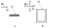
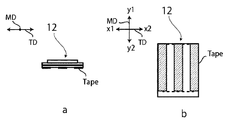
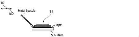
- the power storage device In various products such as electrical equipment, the power storage device is firmly fixed to the product housing with double-sided tape or adhesive. Therefore, when the power storage device is removed from the housing of the product, a large external force is applied to the power storage device. Specifically, in general, the power storage device is removed from the housing by using a metal spatula or the like, and a large external force is applied to the power storage device. If a large external force is applied to the exterior material for the energy storage device made of a film-like laminate when the energy storage device is removed, the exterior material for the energy storage device may be damaged.
- the present disclosure discloses an exterior material for a power storage device in which damage to the exterior material for the power storage device is suppressed when the power storage device fixed to the housing with double-sided tape or the like is peeled off from the housing.
- the main purpose is to provide.
- the inventors of the present disclosure have made diligent studies to solve the above problems.
- it is composed of a laminate having at least a base material layer, a barrier layer, and a thermosetting resin layer in order from the outside, and the base material layer contains a polyamide film, and Fourier transform infrared spectroscopy.
- the exterior material for a power storage device in which the crystallization index of the polyamide film measured from the outside of the base material layer by the ATR method of the method is equal to or higher than a predetermined value covers the power storage device fixed to the housing with double-sided tape or the like. It has been found that damage to the exterior material for the power storage device is suppressed when the material is peeled off from the body.
- the present disclosure has been completed by further studies based on these findings. That is, the present disclosure provides the inventions of the following aspects. From the outside, it is composed of a laminate having at least a base material layer, a barrier layer, and a thermosetting resin layer.
- the base material layer contains a polyamide film and An exterior material for a power storage device, wherein the crystallization index of the polyamide film measured from the outside of the base material layer by the ATR method of Fourier transform infrared spectroscopy is 1.50 or more.
- Exterior materials can be provided. Further, according to the present disclosure, a method for manufacturing an exterior material for a power storage device, a power storage device using the exterior material for the power storage device, and a polyamide film suitable for use as a base material layer for the exterior material for the power storage device are provided. It can also be provided.
- the exterior material for a power storage device of the present disclosure is composed of a laminate having at least a base material layer, a barrier layer, and a thermosetting resin layer in this order from the outside, and the base material layer contains a polyamide film.
- the crystallization index of the polyamide film measured from the outside of the base material layer by the ATR method of Fourier transform infrared spectroscopy is 1.50 or more.
- the exterior material for a power storage device of the present disclosure is prevented from being damaged when the power storage device fixed to the housing with double-sided tape or the like is peeled off from the housing.
- the exterior material for the power storage device of the present disclosure will be described in detail.
- the numerical range indicated by “-” means “greater than or equal to” and “less than or equal to”.
- the notation of 2 to 15 mm means 2 mm or more and 15 mm or less.
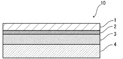
- the exterior material 10 for power storage device of the present disclosure is, for example, as shown in FIG. 1, in order from the outside, a base material layer 1, a barrier layer 3, and a thermosetting resin layer 4. It is composed of a laminated body comprising.
- the base material layer 1 is on the outermost layer side
- the thermosetting resin layer 4 is on the innermost layer.
- the peripheral portion is heat-sealed with the thermosetting resin layers 4 of the power storage device exterior material 10 facing each other.
- the power storage device element is housed in the space formed by.
- the heat-sealing resin layer 4 side is inside the barrier layer 3 and the base material layer 1 side is more than the barrier layer 3 with the barrier layer 3 as a reference. It is the outside.
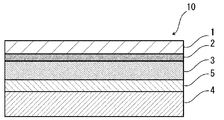
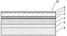
- the exterior material 10 for a power storage device is used as necessary for the purpose of enhancing the adhesiveness between the base material layer 1 and the barrier layer 3 and the like. It may have an adhesive layer 2. Further, for example, as shown in FIGS. 3 and 4, the adhesive layer 5 is required between the barrier layer 3 and the thermosetting resin layer 4 for the purpose of enhancing the adhesiveness between the layers. May have. Further, as shown in FIG. 5, a surface coating layer 6 or the like may be provided on the outside of the base material layer 1 (the side opposite to the thermosetting resin layer 4 side), if necessary.
- the thickness of the laminate constituting the exterior material 10 for the power storage device is not particularly limited, but the upper limit is preferably about 180 ⁇ m or less, about 155 ⁇ m or less, about 120 ⁇ m or less from the viewpoint of cost reduction, energy density improvement, and the like. From the viewpoint of maintaining the function of the exterior material for the power storage device, which is to protect the power storage device element, the lower limit is preferably about 35 ⁇ m or more, about 45 ⁇ m or more, and about 60 ⁇ m or more, and the preferable range is about 60 ⁇ m or more.
- 60 to 120 ⁇ m is particularly preferable.
- the ratio of the total thickness of the adhesive layer 5, the thermosetting resin layer 4, and the surface coating layer 6 provided as needed is preferably 90% or more, more preferably 95% or more. More preferably, it is 98% or more.
- the exterior material 10 for a power storage device of the present disclosure includes a base material layer 1, an adhesive layer 2, a barrier layer 3, an adhesive layer 5, and a thermosetting resin layer 4, the exterior for the power storage device
- the ratio of the total thickness of each of these layers to the thickness (total thickness) of the laminate constituting the material 10 is preferably 90% or more, more preferably 95% or more, and further preferably 98% or more.
- the base material layer 1 of the exterior material 10 for a power storage device of the present disclosure contains a polyamide film, and the crystallization index of the polyamide film measured from the outside of the base material layer 1 by the ATR method of Fourier transform infrared spectroscopy. However, it is 1.50 or more.
- the method for measuring the crystallization index of the base material layer 1 of the exterior material 10 for a power storage device of the present disclosure is as follows.
- a sample is prepared by cutting the exterior material for a power storage device into a square of 100 mm ⁇ 100 mm.
- the surface of the polyamide film located on the outside of the obtained sample is subjected to infrared absorption spectrum measurement in an environment of a temperature of 25 ° C. and a relative humidity of 50% by using the ATR measurement mode of FT-IR.
- Thermo Fisher Scientific Co., Ltd .: Nicolet iS10 can be used as the apparatus.
- the peak intensity P around 1200 cm -1 derived from the absorption of ⁇ crystals of nylon and the peak intensity Q around 1370 cm -1 derived from the absorption unrelated to the crystals were measured, and the peak intensity Q was measured.
- the intensity ratio X P / Q of the peak intensity P with respect to the crystallization index is calculated.
- the power storage device exterior material 10 When the outer surface of the power storage device exterior material 10 is made of the polyamide film of the base material layer 1, the power storage device exterior material 10 can be used as it is as a measurement target of the crystallization index. Further, when the base material layer 1 has a multilayer structure as described later and a resin film (for example, polyester film) different from the polyamide film is located outside the polyamide film, or when the base material layer 1 has a multilayer structure.
- the outer surface of the exterior material 10 for a power storage device is not composed of the polyamide film of the base material layer 1, such as when the surface coating layer 6 described later is laminated on the outside, the position is located outside the polyamide film.
- the crystallization index can be measured in a state where the layer is removed from the exterior material 10 for a power storage device and the surface of the polyamide film is exposed.
- the crystallization index may be 1.50 or more, but from the viewpoint of more effectively suppressing damage to the power storage device exterior material during the above-mentioned peeling. Therefore, it is more preferably 1.55 or more, further preferably 1.60 or more, and particularly preferably 1.65 or more.
- the upper limit of the crystallization index is not particularly limited, and examples thereof include 2.50 or less and 1.80 or less.
- Preferred ranges of the crystallization index include, for example, 1.50 to 2.50, 1.60 to 2.50, 1.65 to 2.50, 1.50 to 1.80, and 1.60 to 1. 80, 1.65 to 1.80 and the like can be mentioned.
- the draw ratio, the heat fixing temperature, and the post-heating in the manufacturing process of the polyamide film are used.
- a method of promoting crystallization (promoting the formation of ⁇ -crystals) depending on the temperature and time of the film can be mentioned.
- the base material layer 1 is a layer provided for the purpose of exerting a function as a base material of an exterior material for a power storage device.
- the base material layer 1 is located on the outer layer side of the exterior material for the power storage device.
- the base material layer 1 contains a polyamide film.
- the crystallization index of the polyamide film measured from the outside of the base material layer 1 by the ATR method of Fourier transform infrared spectroscopy is 1.50 or more.
- the polyamide forming the polyamide film may be any polyamide having ⁇ crystals, and specifically, nylon 6, nylon 66, nylon 46, an aliphatic polyamide such as a copolymer of nylon 6 and nylon 66, or the like may be used. Can be mentioned. These polyamides may be used alone or in combination of two or more.
- the polyamide film is preferably a nylon film.
- the polyamide film may be an unstretched film or a stretched film.
- the base material layer 1 contains an unstretched film
- a resin polyamide
- Examples of the method for applying the resin include a roll coating method, a gravure coating method, and an extrusion coating method.
- the base material layer 1 is a stretched film, a stretched film prepared in advance is bonded when laminating the layers of the exterior material 10 for a power storage device.
- Examples of the stretched film include a uniaxially stretched film and a biaxially stretched film, and a biaxially stretched film is preferable.
- Examples of the stretching method for forming the biaxially stretched film include a sequential biaxial stretching method, an inflation method, and a simultaneous biaxial stretching method.
- the polyamide film is particularly preferably a biaxially stretched nylon film.
- a polyamide film having a crystallization index of 1.50 or more measured by the ATR method of Fourier transform infrared spectroscopy can be produced as the base material layer 1.
- the crystallization index can be increased by applying heat to the polyamide film in the manufacturing process of the exterior material 10 for the power storage device, and the crystallization index can be set to 1.50 or more.
- the crystallization index measured by the ATR method of Fourier transform infrared spectroscopy is 1.50 or more. It is preferably produced by using a certain polyamide film as the base material layer 1.
- the present disclosure is made by using a polyamide film whose crystallization index has been adjusted to 1.50 or more in advance for the base material layer 1 and laminating it with each layer such as the barrier layer 3 and the thermosetting resin layer 4. It is preferable to manufacture the exterior material 10 for a power storage device. As shown in Examples described later, the polyamide film that is laminated on the exterior material 10 for the power storage device and contained in the base material layer 1 is more than the polyamide film before being applied to the exterior material 10 for the power storage device. The crystallization index of the film can be increased.
- the thickness of the polyamide film is preferably about 3 ⁇ m or more, more preferably about 10 ⁇ m or more, and more preferably about 10 ⁇ m or more, from the viewpoint of more effectively suppressing damage to the exterior material for the power storage device during the above-mentioned peeling. It is preferably about 50 ⁇ m or less, more preferably about 35 ⁇ m or less, and preferred ranges include about 3 to 50 ⁇ m, about 3 to 35 ⁇ m, about 10 to 50 ⁇ m, and about 10 to 35 ⁇ m, among which 10 to 35 ⁇ m. The degree is particularly preferable.
- the base material layer 1 may further have a resin film different from the polyamide film.
- the resin that forms a resin film different from the polyamide film include resins such as polyester, polyolefin, epoxy resin, acrylic resin, fluororesin, polyurethane, silicon resin, and phenol resin, and modified products of these resins. .. Further, the resin may be a copolymer of these resins, or may be a modified product of the copolymer. Further, it may be a mixture of these resins. Among these, polyester is preferable.
- polyester examples include polyethylene terephthalate, polybutylene terephthalate, polyethylene naphthalate, polybutylene naphthalate, polyethylene isophthalate, and copolymerized polyester.
- copolymerized polyester examples include a copolymerized polyester containing ethylene terephthalate as a repeating unit.
- copolymer polyester (hereinafter abbreviated after polyethylene (terephthalate / isophthalate)), polyethylene (terephthalate / adipate), polyethylene (terephthalate / terephthalate / (Sodium sulfoisophthalate), polyethylene (terephthalate / sodium isophthalate), polyethylene (terephthalate / phenyl-dicarboxylate), polyethylene (terephthalate / decandicarboxylate) and the like.
- These polyesters may be used alone or in combination of two or more. Of these, polyethylene terephthalate and polybutylene terephthalate are preferable.
- the polyester film is preferably a stretched polyester film, and more preferably a biaxially stretched polyester film.
- the polyester film is particularly preferably a biaxially stretched polyethylene terephthalate film or a biaxially stretched polybutylene terephthalate film.
- the thickness of the other resin film is not particularly limited as long as it does not interfere with the effect of the present invention, and is preferably about 3 ⁇ m or more. It is preferably about 10 ⁇ m or more, preferably about 50 ⁇ m or less, more preferably about 35 ⁇ m or less, and the preferred range is about 3 to 50 ⁇ m, about 3 to 35 ⁇ m, about 10 to 50 ⁇ m, and about 10 to 35 ⁇ m. Among these, about 10 to 35 ⁇ m is particularly preferable.
- the base material layer 1 may be a single layer or may be composed of two or more layers as long as it contains a polyamide film, and from the viewpoint of thinning the exterior material 10 for a power storage device, the polyamide film It is preferably a single layer.
- the base material layer 1 may be a laminated body in which a resin film is laminated with an adhesive or the like, or the resin is co-extruded to form two or more layers. It may be a laminated body of the resin film. Further, the laminated body of the resin film obtained by co-extruding the resin into two or more layers may be used as the base material layer 1 without being stretched, or may be uniaxially stretched or biaxially stretched as the base material layer 1.
- the laminate of two or more layers of resin film in the base material layer 1 include a laminate of a polyester film and a nylon film, a laminate of two or more layers of nylon film, and the like, preferably stretched nylon.
- a laminate of a film and a stretched polyester film, and a laminate of two or more layers of stretched nylon film are preferable.
- the base material layer 1 is a laminate of two layers of resin film
- a laminate of polyamide resin film and polyamide resin film, or a laminate of polyester resin film and polyamide resin film is preferable, and nylon film and nylon film.
- a laminate or a laminate of a polyethylene terephthalate film and a nylon film is more preferable.
- the polyester resin film is the base material layer 1. It is preferably located in the outermost layer.
- the two or more layers of resin films may be laminated via an adhesive.
- Preferred adhesives include those similar to the adhesives exemplified in the adhesive layer 2 described later.
- the method of laminating two or more layers of resin films is not particularly limited, and known methods can be adopted. Examples thereof include a dry laminating method, a sandwich laminating method, an extrusion laminating method, and a thermal laminating method, and a dry laminating method is preferable.
- the laminating method can be mentioned.
- the thickness of the adhesive is, for example, about 2 to 5 ⁇ m.
- an anchor coat layer may be formed on the resin film and laminated. Examples of the anchor coat layer include the same adhesives as those exemplified in the adhesive layer 2 described later. At this time, the thickness of the anchor coat layer is, for example, about 0.01 to 1.0 ⁇ m.
- additives such as a lubricant, a flame retardant, an antiblocking agent, an antioxidant, a light stabilizer, a tackifier, and an antistatic agent are present on at least one of the surface and the inside of the base material layer 1. Good. Only one type of additive may be used, or two or more types may be mixed and used.
- the lubricant is present on the surface of the base material layer 1.
- the lubricant is not particularly limited, but an amide-based lubricant is preferable.
- Specific examples of the amide-based lubricant include saturated fatty acid amides, unsaturated fatty acid amides, substituted amides, methylol amides, saturated fatty acid bisamides, unsaturated fatty acid bisamides, fatty acid ester amides, and aromatic bisamides.
- saturated fatty acid amide examples include lauric acid amide, palmitic acid amide, stearic acid amide, bechenic acid amide, hydroxystearic acid amide and the like.
- unsaturated fatty acid amides include oleic acid amides and erucic acid amides.
- substituted amide examples include N-oleyl palmitic acid amide, N-stearyl stearic acid amide, N-stearyl oleic acid amide, N-oleyl stearic acid amide, N-stearyl erucate amide and the like.
- methylolamide examples include methylolstearic acid amide.
- saturated fatty acid bisamide examples include methylene bisstearic acid amide, ethylene biscapric acid amide, ethylene bislauric acid amide, ethylene bisstearic acid amide, ethylene bishydroxystearic acid amide, ethylene bisbechenic acid amide, and hexamethylene bisstearic.
- saturated fatty acid bisamide examples include acid amides, hexamethylene bisbechenic acid amides, hexamethylene hydroxystearic acid amides, N, N'-distearyl adipate amides, and N, N'-distearyl sebacic acid amides.
- unsaturated fatty acid bisamides include ethylene bisoleic acid amide, ethylene biserucic acid amide, hexamethylene bisoleic acid amide, N, N'-diorail adipic acid amide, and N, N'-diorail sebacic acid amide. And so on.
- Specific examples of the fatty acid ester amide include stearoamide ethyl stearate and the like.
- Specific examples of the aromatic bisamide include m-xylylene bisstearic acid amide, m-xylylene bishydroxystearic acid amide, and N, N'-distearyl isophthalic acid amide.
- One type of lubricant may be used alone, or two or more types may be used in combination.
- the amount of the lubricant is not particularly limited, but is preferably about 3 mg / m 2 or more, more preferably about 4 to 15 mg / m 2 , and further preferably 5 to 14 mg. / M 2 is mentioned.
- the lubricant existing on the surface of the base material layer 1 may be one in which the lubricant contained in the resin constituting the base material layer 1 is exuded, or one in which the lubricant is applied to the surface of the base material layer 1. You may.
- the total thickness of the base material layer 1 is not particularly limited as long as it functions as a base material, and examples thereof include about 3 to 50 ⁇ m, preferably about 10 to 35 ⁇ m.
- the exterior material for a power storage device of the present disclosure is placed on the base material layer 1 (opposite to the barrier layer 3 side of the base material layer 1) as necessary for the purpose of improving printability and moldability.
- a coat layer (not shown) may be provided.
- the coat layer is provided so as to be in contact with the base material layer 1.
- the thickness of the coat layer is not particularly limited as long as it exhibits the above-mentioned function as the coat layer, and is, for example, about 0.01 to 0.40 ⁇ m, preferably about 0.01 to 0.30 ⁇ m, and more preferably 0.1. The range is about 0.30 ⁇ m. When the thickness is 0.01 ⁇ m or more, a layer having a uniform film thickness can be formed on the base material layer 1. As a result, it is possible to enable uniform printing without causing unevenness in the printability of the exterior material for the power storage device of the present disclosure, and to obtain uniform moldability.
- the resin forming the coat layer examples include polyvinylidene chloride, vinylidene chloride-vinyl chloride copolymer, polyolefin, acid-modified polyolefin, polyester, epoxy resin, phenol resin, fluororesin, cellulose ester, polyurethane, acrylic resin, and polyamide. And various synthetic resins such as. Among these, polyurethane, polyester and acrylic resin are preferable.
- the coat layer may contain a lubricant or an additive, if necessary, in order to improve the slipperiness.
- a lubricant include the same lubricants as those described above.
- the additive the same additives as those exemplified in the surface coating layer 6 described later are exemplified. The content and particle size of these lubricants and additives are appropriately adjusted according to the thickness of the coat layer.
- the exterior material for a power storage device of the present disclosure has, if necessary, one side of the base material layer 1 (the barrier layer 3 side of the base material layer 1) for the purpose of improving the adhesiveness with the layer adjacent to the base material layer.
- a coat layer (not shown) may be provided on both sides of the base material layer 1 on the side opposite to the barrier layer 3). That is, the coat layer provided on the base material layer may be a layer for the purpose of improving printability, moldability, etc., or a layer for the purpose of improving the adhesiveness of the base material layer. May be good.
- the resin forming the coat layer and the thickness similar to the resin and the thickness of the coat layer described above are exemplified. Further, although the above-mentioned lubricants and additives may be included, it is preferable not to include the lubricants and additives when there is a layer adjacent to the base material layer of the coat layer.
- the adhesive layer 2 is a layer provided between the base material layer 1 and the barrier layer 3 as necessary for the purpose of enhancing the adhesiveness.
- the adhesive layer 2 is formed by an adhesive capable of adhering the base material layer 1 and the barrier layer 3.
- the adhesive used for forming the adhesive layer 2 is not limited, but may be any of a chemical reaction type, a solvent volatilization type, a heat melting type, a hot pressure type and the like. Further, it may be a two-component curable adhesive (two-component adhesive), a one-component curable adhesive (one-component adhesive), or a resin that does not involve a curing reaction. Further, the adhesive layer 2 may be a single layer or a multilayer.
- the adhesive component contained in the adhesive include polyesters such as polyethylene terephthalate, polybutylene terephthalate, polyethylene naphthalate, polybutylene naphthalate, polyethylene isophthalate, and copolymerized polyester; polyether; polyurethane; epoxy resin; Phenolic resin; Polyolefin such as nylon 6, nylon 66, nylon 12, copolymerized polyamide; polyolefin resin such as polyolefin, cyclic polyolefin, acid-modified polyolefin, acid-modified cyclic polyolefin; Polyvinyl acetate; Cellulose; (meth) acrylic resin; Polyethylene; Polyolefin; Amino resin such as urea resin and melamine resin; Rubber such as chloroprene rubber, nitrile rubber and styrene-butadiene rubber; Silicone resin and the like.
- polyesters such as polyethylene terephthalate, polybutylene terephthalate, poly
- adhesive components may be used alone or in combination of two or more.
- a polyurethane adhesive is preferable.
- the resin as an adhesive component can be used in combination with an appropriate curing agent to increase the adhesive strength.
- An appropriate curing agent is selected from polyisocyanate, polyfunctional epoxy resin, oxazoline group-containing polymer, polyamine resin, acid anhydride and the like, depending on the functional group of the adhesive component.
- polyurethane adhesive examples include a polyurethane adhesive containing a main agent containing a polyol compound and a curing agent containing an isocyanate compound.
- a polyol such as a polyester polyol, a polyether polyol, and an acrylic polyol is used as a main component, and an aromatic or aliphatic polyisocyanate is used as a curing agent.
- the polyol compound it is preferable to use a polyester polyol having a hydroxyl group in the side chain in addition to the hydroxyl group at the end of the repeating unit.
- the adhesive layer 2 is formed of the polyurethane adhesive, excellent electrolyte resistance is imparted to the exterior material for the power storage device, and even if the electrolyte adheres to the side surface, the base material layer 1 is suppressed from peeling off. ..
- the adhesive layer 2 may contain a colorant, a thermoplastic elastomer, a tackifier, a filler, etc., as long as the adhesiveness is not hindered, the addition of other components is permitted. Since the adhesive layer 2 contains a colorant, the exterior material for the power storage device can be colored. As the colorant, known pigments, dyes and the like can be used. Further, only one type of colorant may be used, or two or more types may be mixed and used.
- the type of pigment is not particularly limited as long as it does not impair the adhesiveness of the adhesive layer 2.
- organic pigments include azo-based, phthalocyanine-based, quinacridone-based, anthracinone-based, dioxazine-based, indigothioindigo-based, perinone-perylene-based, isowearnine-based, and benzimidazolone-based pigments, which are inorganic.
- pigments include carbon black pigments, titanium oxide pigments, cadmium pigments, lead pigments, chromium oxide pigments, iron pigments, copper pigments, and other pigments such as mica (mica) fine powder and fish scale foil. Be done.
- the pigment can be used alone, but two or more kinds can be mixed and used, for example, a mixture of an organic pigment and an inorganic pigment may be used.
- colorants for example, carbon black is preferable in order to make the appearance of the exterior material for a power storage device black.
- the average particle size of the pigment is not particularly limited, and examples thereof include about 0.05 to 5 ⁇ m, preferably about 0.08 to 2 ⁇ m.
- the average particle size of the pigment is the median diameter measured by a laser diffraction / scattering type particle size distribution measuring device.
- the content of the pigment in the adhesive layer 2 is not particularly limited as long as the exterior material for the power storage device is colored, and examples thereof include about 5 to 60% by mass, preferably 8 to 40% by mass.
- the thickness of the adhesive layer 2 is not particularly limited as long as the base material layer 1 and the barrier layer 3 can be adhered to each other, but the lower limit is, for example, about 1 ⁇ m or more and about 2 ⁇ m or more, and the upper limit is about 10 ⁇ m or less. , About 5 ⁇ m or less, and preferred ranges include about 1 to 10 ⁇ m, about 1 to 5 ⁇ m, about 2 to 10 ⁇ m, and about 2 to 5 ⁇ m.
- the colored layer is a layer provided between the base material layer 1 and the barrier layer 3 as needed (not shown).
- a colored layer may be provided between the base material layer 1 and the adhesive layer 2 and between the adhesive layer 2 and the barrier layer 3. Further, a colored layer may be provided on the outside of the base material layer 1. By providing the coloring layer, the exterior material for the power storage device can be colored.
- the colored layer can be formed, for example, by applying an ink containing a colorant to the surface of the base material layer 1, the surface of the adhesive layer 2, or the surface of the barrier layer 3.
- a colorant known pigments, dyes and the like can be used. Further, only one type of colorant may be used, or two or more types may be mixed and used.
- colorant contained in the colored layer include the same as those exemplified in the column of [Adhesive layer 2].
- the barrier layer 3 is at least a layer that suppresses the infiltration of water.
- the barrier layer 3 examples include a metal foil having a barrier property, a thin-film deposition film, a resin layer, and the like.
- the vapor deposition film examples include a metal vapor deposition film, an inorganic oxide vapor deposition film, a carbon-containing inorganic oxide vapor deposition film, and the like
- the resin layer includes polymers and tetras mainly composed of polyvinylidene chloride and chlorotrifluoroethylene (CTFE).
- CTFE chlorotrifluoroethylene
- TFE fluoroethylene
- TFE fluoroethylene
- TFE fluoroalkyl group
- fluorine-containing resins such as polymers containing a fluoroalkyl unit as a main component
- ethylene vinyl alcohol copolymers examples include ethylene vinyl alcohol copolymers.
- examples of the barrier layer 3 include a resin film provided with at least one of these vapor-deposited films and a resin layer.
- a plurality of barrier layers 3 may be provided.
- the barrier layer 3 preferably includes a layer made of a metal material.
- Specific examples of the metal material constituting the barrier layer 3 include an aluminum alloy, stainless steel, titanium steel, and a steel plate.
- the metal material includes at least one of an aluminum alloy foil and a stainless steel foil. Is preferable.
- the aluminum alloy foil is more preferably a soft aluminum alloy foil composed of, for example, an annealed aluminum alloy, and from the viewpoint of further improving the moldability. Therefore, it is preferable that the aluminum alloy foil contains iron.
- the iron-containing aluminum alloy foil (100% by mass) the iron content is preferably 0.1 to 9.0% by mass, more preferably 0.5 to 2.0% by mass.
- the iron content is 0.1% by mass or more, an exterior material for a power storage device having more excellent moldability can be obtained.
- the iron content is 9.0% by mass or less, a more flexible exterior material for a power storage device can be obtained.
- the soft aluminum alloy foil for example, an aluminum alloy having a composition specified by JIS H4160: 1994 A8021HO, JIS H4160: 1994 A8079HO, JIS H4000: 2014 A8021PO, or JIS H4000: 2014 A8077P-O. Foil is mentioned. Further, if necessary, silicon, magnesium, copper, manganese and the like may be added. Further, softening can be performed by annealing or the like.
- stainless steel foils examples include austenite-based, ferrite-based, austenite-ferritic-based, martensitic-based, and precipitation-hardened stainless steel foils. Further, from the viewpoint of providing an exterior material for a power storage device having excellent moldability, the stainless steel foil is preferably made of austenitic stainless steel.
- austenitic stainless steel constituting the stainless steel foil include SUS304, SUS301, and SUS316L, and among these, SUS304 is particularly preferable.
- the thickness of the barrier layer 3 may at least exhibit a function as a barrier layer that suppresses the infiltration of water, and is, for example, about 9 to 200 ⁇ m.
- the thickness of the barrier layer 3 is, for example, preferably about 85 ⁇ m or less, more preferably about 50 ⁇ m or less, still more preferably about 40 ⁇ m or less, particularly preferably about 35 ⁇ m or less, and the lower limit is preferably about about.
- 10 ⁇ m or more, more preferably about 20 ⁇ m or more, more preferably about 25 ⁇ m or more, and preferable ranges of the thickness are about 10 to 85 ⁇ m, about 10 to 50 ⁇ m, about 10 to 40 ⁇ m, about 10 to 35 ⁇ m, and about 20 to.
- the barrier layer 3 is made of an aluminum alloy foil, the above range is particularly preferable.
- the upper limit of the thickness of the stainless steel foil is preferably about 60 ⁇ m or less, more preferably about 50 ⁇ m or less, still more preferably about 40 ⁇ m or less. More preferably, it is about 30 ⁇ m or less, particularly preferably about 25 ⁇ m or less, and the lower limit is preferably about 10 ⁇ m or more, more preferably about 15 ⁇ m or more, and the preferred thickness range is about 10 to 60 ⁇ m, 10 Examples thereof include about 50 ⁇ m, about 10 to 40 ⁇ m, about 10 to 30 ⁇ m, about 10 to 25 ⁇ m, about 15 to 60 ⁇ m, about 15 to 50 ⁇ m, about 15 to 40 ⁇ m, about 15 to 30 ⁇ m, and about 15 to 25 ⁇ m.
- the barrier layer 3 is a metal foil, it is preferable that a corrosion-resistant film is provided at least on the surface opposite to the base material layer in order to prevent dissolution and corrosion.
- the barrier layer 3 may be provided with a corrosion-resistant film on both sides.
- the corrosion-resistant film is, for example, a hot-water transformation treatment such as boehmite treatment, a chemical conversion treatment, anodizing treatment, a plating treatment such as nickel or chromium, and a corrosion prevention treatment for applying a coating agent on the surface of the barrier layer.
- This is a thin film that makes the barrier layer corrosive.
- the treatment for forming the corrosion-resistant film one type may be performed, or two or more types may be combined.
- the hydrothermal modification treatment and the anodizing treatment are treatments in which the surface of the metal foil is dissolved by a treatment agent to form a metal compound having excellent corrosion resistance. Note that these processes may be included in the definition of chemical conversion process.
- the barrier layer 3 has a corrosion-resistant film, the barrier layer 3 includes the corrosion-resistant film.
- the corrosion-resistant film is formed by preventing delamination between the barrier layer (for example, aluminum alloy foil) and the base material layer during molding of the exterior material for a power storage device, and by hydrogen fluoride generated by the reaction between the electrolyte and water. , Melting and corrosion of the barrier layer surface, especially when the barrier layer is an aluminum alloy foil, it prevents the aluminum oxide existing on the barrier layer surface from melting and corroding, and the adhesiveness (wetness) of the barrier layer surface. The effect of preventing delamination between the base material layer and the barrier layer during heat sealing and preventing delamination between the base material layer and the barrier layer during molding is shown.
- the barrier layer for example, aluminum alloy foil
- Various corrosion-resistant films formed by chemical conversion treatment are known, and mainly, at least one of phosphate, chromate, fluoride, triazinethiol compound, and rare earth oxide. Examples include a corrosion-resistant film containing.
- Examples of the chemical conversion treatment using a phosphate or a chromate include a chromate chromate treatment, a phosphoric chromate treatment, a phosphoric acid-chromate treatment, a chromate treatment, and the like, and chromium used in these treatments.
- Examples of the compound include chromium nitrate, chromium fluoride, chromium sulfate, chromium acetate, chromium oxalate, chromium dichromate, acetylacetate chromate, chromium chloride, and chromium potassium sulfate.
- examples of the phosphorus compound used in these treatments include sodium phosphate, potassium phosphate, ammonium phosphate, polyphosphoric acid and the like.
- examples of the chromate treatment include etching chromate treatment, electrolytic chromate treatment, and coating type chromate treatment, and coating type chromate treatment is preferable.
- At least the inner layer side surface of the barrier layer (for example, aluminum alloy foil) is first known as an alkali dipping method, an electrolytic cleaning method, an acid cleaning method, an electrolytic acid cleaning method, an acid activation method and the like.
- Degreasing treatment is performed by the treatment method, and then, a metal phosphate such as Cr (chromium) phosphate, Ti (titanium) phosphate, Zr (zyroxide) salt, Zn (zinc) phosphate, etc. is applied to the degreased surface.
- a treatment liquid for example, various solvents such as water, alcohol-based solvent, hydrocarbon-based solvent, ketone-based solvent, ester-based solvent, and ether-based solvent can be used, and water is preferable.
- examples of the resin component used at this time include polymers such as phenolic resin and acrylic resin, and an amination phenol polymer having a repeating unit represented by the following general formulas (1) to (4) can be used. Examples thereof include the chromate treatment used. In the aminated phenol polymer, the repeating units represented by the following general formulas (1) to (4) may be contained alone or in any combination of two or more. May be good.
- the acrylic resin shall be polyacrylic acid, acrylic acid methacrylate copolymer, acrylic acid maleic acid copolymer, acrylic acid styrene copolymer, or derivatives of these sodium salts, ammonium salts, amine salts, etc. Is preferable.
- polyacrylic acid means a polymer of acrylic acid.
- the acrylic resin is preferably a copolymer of acrylic acid and a dicarboxylic acid or a dicarboxylic acid anhydride, and an ammonium salt, a sodium salt, or a copolymer of an acrylic acid and a dicarboxylic acid or a dicarboxylic acid anhydride.
- it is preferably an amine salt. Only one type of acrylic resin may be used, or two or more types may be mixed and used.
- X represents a hydrogen atom, a hydroxy group, an alkyl group, a hydroxyalkyl group, an allyl group or a benzyl group.
- R 1 and R 2 represent a hydroxy group, an alkyl group, or a hydroxyalkyl group, respectively, which are the same or different.
- examples of the alkyl group represented by X, R 1 and R 2 include a methyl group, an ethyl group, an n-propyl group, an isopropyl group, an n-butyl group and an isobutyl group.
- Examples thereof include straight-chain or branched alkyl groups having 1 to 4 carbon atoms such as tert-butyl groups.
- Examples of the hydroxyalkyl groups represented by X, R 1 and R 2 include hydroxymethyl group, 1-hydroxyethyl group, 2-hydroxyethyl group, 1-hydroxypropyl group, 2-hydroxypropyl group and 3-. Linear or branched chain with 1 to 4 carbon atoms in which one hydroxy group such as hydroxypropyl group, 1-hydroxybutyl group, 2-hydroxybutyl group, 3-hydroxybutyl group, 4-hydroxybutyl group is substituted.
- Alkyl groups can be mentioned.
- the alkyl group and the hydroxyalkyl group represented by X, R 1 and R 2 may be the same or different, respectively.
- X is preferably a hydrogen atom, a hydroxy group or a hydroxyalkyl group.
- the number average molecular weight of the aminated phenol polymer having the repeating unit represented by the general formulas (1) to (4) is, for example, preferably about 5 to 1,000,000, and preferably about 1,000 to 20,000. More preferred.
- the amination phenol polymer for example, polycondenses a phenol compound or a naphthol compound with formaldehyde to produce a polymer composed of repeating units represented by the above general formula (1) or general formula (3), and then formsaldehyde. It is produced by introducing a functional group (-CH 2 NR 1 R 2 ) into the polymer obtained above using amine (R 1 R 2 NH).
- the aminated phenol polymer is used alone or in combination of two or more.
- the corrosion resistant film it is formed by a coating type corrosion prevention treatment in which a coating agent containing at least one selected from the group consisting of a rare earth element oxide sol, an anionic polymer, and a cationic polymer is applied.
- the thin film to be used is mentioned.
- the coating agent may further contain phosphoric acid or phosphate, a cross-linking agent for cross-linking the polymer.
- fine particles of rare earth element oxide for example, particles having an average particle size of 100 nm or less
- the rare earth element oxide examples include cerium oxide, yttrium oxide, neodymium oxide, lanthanum oxide and the like, and cerium oxide is preferable from the viewpoint of further improving adhesion.
- the rare earth element oxide contained in the corrosion-resistant film may be used alone or in combination of two or more.
- various solvents such as water, alcohol solvent, hydrocarbon solvent, ketone solvent, ester solvent, ether solvent and the like can be used, and water is preferable.
- the cationic polymer examples include polyethyleneimine, an ionic polymer complex composed of polyethyleneimine and a polymer having a carboxylic acid, a primary amine graft acrylic resin obtained by graft-polymerizing a primary amine on an acrylic main skeleton, polyallylamine or a derivative thereof. , Amination phenol and the like are preferable.
- the anionic polymer is preferably a poly (meth) acrylic acid or a salt thereof, or a copolymer containing (meth) acrylic acid or a salt thereof as a main component.
- the cross-linking agent is at least one selected from the group consisting of a compound having a functional group of any of an isocyanate group, a glycidyl group, a carboxyl group and an oxazoline group and a silane coupling agent.
- the phosphoric acid or phosphate is condensed phosphoric acid or condensed phosphate.
- a film in which fine particles of metal oxides such as aluminum oxide, titanium oxide, cerium oxide, and tin oxide and barium sulfate are dispersed in phosphoric acid is applied to the surface of the barrier layer, and 150 Examples thereof include those formed by performing a baking treatment at a temperature of ° C. or higher.
- the corrosion-resistant film may have a laminated structure in which at least one of a cationic polymer and an anionic polymer is further laminated, if necessary.
- a cationic polymer and an anionic polymer include those described above.
- composition of the corrosion-resistant film can be analyzed by using, for example, a time-of-flight secondary ion mass spectrometry method.
- the amount of the corrosion-resistant film formed on the surface of the barrier layer 3 in the chemical conversion treatment is not particularly limited, but for example, in the case of performing a coating type chromate treatment, a chromic acid compound per 1 m 2 of the surface of the barrier layer 3 Is, for example, about 0.5 to 50 mg, preferably about 1.0 to 40 mg in terms of chromium, and the phosphorus compound is, for example, about 0.5 to 50 mg, preferably about 1.0 to 40 mg in terms of phosphorus, and an amination phenol polymer. Is preferably contained in a proportion of, for example, about 1.0 to 200 mg, preferably about 5.0 to 150 mg.
- the thickness of the corrosion-resistant film is not particularly limited, but is preferably about 1 nm to 20 ⁇ m, more preferably 1 nm to 100 nm, from the viewpoint of the cohesive force of the film and the adhesion to the barrier layer and the thermosetting resin layer. The degree, more preferably about 1 nm to 50 nm.
- the thickness of the corrosion-resistant film can be measured by observation with a transmission electron microscope or a combination of observation with a transmission electron microscope and energy dispersion type X-ray spectroscopy or electron beam energy loss spectroscopy.
- the time-of-flight secondary ion mass spectrometry analysis of the composition of the corrosion resistant coating using, for example, secondary ion consisting Ce and P and O (e.g., Ce 2 PO 4 +, CePO 4 - at least 1, such as species) or, for example, secondary ion of Cr and P and O (e.g., CrPO 2 +, CrPO 4 - peak derived from at least one), such as is detected.
- secondary ion consisting Ce and P and O e.g., Ce 2 PO 4 +, CePO 4 - at least 1, such as species
- secondary ion of Cr and P and O e.g., CrPO 2 +, CrPO 4 - peak derived from at least one
- a solution containing a compound used for forming a corrosion-resistant film is applied to the surface of the barrier layer by a bar coating method, a roll coating method, a gravure coating method, a dipping method, or the like, and then the temperature of the barrier layer is applied. It is carried out by heating so that the temperature is about 70 to 200 ° C.
- the barrier layer may be subjected to a degreasing treatment by an alkali dipping method, an electrolytic cleaning method, an acid cleaning method, an electrolytic acid cleaning method or the like in advance. By performing the degreasing treatment in this way, it becomes possible to more efficiently perform the chemical conversion treatment on the surface of the barrier layer.
- an acid degreasing agent in which a fluorine-containing compound is dissolved in an inorganic acid for the degreasing treatment it is possible to form not only the degreasing effect of the metal foil but also the fluoride of the metal which is immobile. In this case, only the degreasing treatment may be performed.
- thermosetting resin layer 4 In the exterior material for a power storage device of the present disclosure, the thermosetting resin layer 4 corresponds to the innermost layer, and has a function of heat-sealing the heat-sealing resin layers with each other when assembling the power storage device to seal the power storage device element. It is a layer (sealant layer) that exerts.
- the resin constituting the heat-fusing resin layer 4 is not particularly limited as long as it can be heat-fused, but a resin containing a polyolefin skeleton such as polyolefin or acid-modified polyolefin is preferable.
- a resin containing a polyolefin skeleton such as polyolefin or acid-modified polyolefin is preferable.
- the fact that the resin constituting the heat-sealing resin layer 4 contains a polyolefin skeleton can be analyzed by, for example, infrared spectroscopy, gas chromatography-mass spectrometry, or the like. Further, when the resin constituting the thermosetting resin layer 4 is analyzed by infrared spectroscopy, it is preferable that a peak derived from maleic anhydride is detected.
- thermosetting resin layer 4 is a layer composed of maleic anhydride-modified polyolefin
- a peak derived from maleic anhydride is detected when measured by infrared spectroscopy.
- the degree of acid denaturation is low, the peak may become small and may not be detected. In that case, it can be analyzed by nuclear magnetic resonance spectroscopy.
- polystyrene resin examples include polyethylenes such as low-density polyethylene, medium-density polyethylene, high-density polyethylene, and linear low-density polyethylene; ethylene- ⁇ -olefin copolymers; homopolypropylene and block copolymers of polypropylene (for example, with propylene).
- Polypropylene such as (block copolymer of ethylene), random copolymer of polypropylene (for example, random copolymer of propylene and ethylene); propylene- ⁇ -olefin copolymer; terpolymer of ethylene-butene-propylene and the like.
- polypropylene is preferable.
- the polyolefin resin may be a block copolymer or a random copolymer.
- One type of these polyolefin resins may be used alone, or two or more types may be used in combination.
- the polyolefin may be a cyclic polyolefin.
- the cyclic polyolefin is a copolymer of an olefin and a cyclic monomer, and examples of the olefin which is a constituent monomer of the cyclic polyolefin include ethylene, propylene, 4-methyl-1-pentene, styrene, butadiene, and isoprene. Be done.
- cyclic monomer which is a constituent monomer of the cyclic polyolefin examples include cyclic alkenes such as norbornene; cyclic diene such as cyclopentadiene, dicyclopentadiene, cyclohexadiene, and norbornadiene. Among these, cyclic alkene is preferable, and norbornene is more preferable.
- the acid-modified polyolefin is a polymer modified by block polymerization or graft polymerization of polyolefin with an acid component.
- the acid-modified polyolefin the above-mentioned polyolefin, a copolymer obtained by copolymerizing the above-mentioned polyolefin with a polar molecule such as acrylic acid or methacrylic acid, or a polymer such as a crosslinked polyolefin can also be used.
- the acid component used for acid modification include carboxylic acids such as maleic acid, acrylic acid, itaconic acid, crotonic acid, maleic anhydride, and itaconic anhydride, or anhydrides thereof.
- the acid-modified polyolefin may be an acid-modified cyclic polyolefin.
- the acid-modified cyclic polyolefin is a polymer obtained by copolymerizing a part of the monomers constituting the cyclic polyolefin in place of the acid component, or by block-polymerizing or graft-polymerizing the acid component with the cyclic polyolefin. is there.
- the acid component used for the acid modification is the same as the acid component used for the modification of the polyolefin.
- Preferred acid-modified polyolefins include polyolefins modified with carboxylic acid or its anhydride, polypropylene modified with carboxylic acid or its anhydride, maleic anhydride-modified polyolefin, and maleic anhydride-modified polypropylene.
- thermosetting resin layer 4 may be formed of one type of resin alone, or may be formed of a blended polymer in which two or more types of resins are combined. Further, the thermosetting resin layer 4 may be formed of only one layer, but may be formed of two or more layers with the same or different resins.
- thermosetting resin layer 4 may contain a lubricant or the like, if necessary.
- a lubricant is not particularly limited, and a known lubricant can be used.
- the lubricant may be used alone or in combination of two or more.
- the lubricant is not particularly limited, but an amide-based lubricant is preferable. Specific examples of the lubricant include those exemplified in the base material layer 1. One type of lubricant may be used alone, or two or more types may be used in combination.
- the amount of the lubricant is not particularly limited, but is preferably about 10 to 50 mg / m 2 from the viewpoint of improving the moldability of the exterior material for the power storage device. , More preferably about 15 to 40 mg / m 2 .
- the lubricant existing on the surface of the thermosetting resin layer 4 may be one in which the lubricant contained in the resin constituting the thermosetting resin layer 4 is exuded, or the lubricant contained in the thermosetting resin layer 4 may be exuded.
- the surface may be coated with a lubricant.
- the thickness of the thermosetting resin layer 4 is not particularly limited as long as the thermosetting resin layers have a function of heat-sealing to seal the power storage device element, but is preferably about 100 ⁇ m or less, preferably. It is about 85 ⁇ m or less, more preferably about 15 to 85 ⁇ m.
- the thickness of the thermosetting resin layer 4 is preferably about 85 ⁇ m or less, more preferably about 15 to 45 ⁇ m, for example.
- the thickness of the thermosetting resin layer 4 is preferably about 20 ⁇ m or more, more preferably 35 to 85 ⁇ m. The degree can be mentioned.
- the adhesive layer 5 is provided between the barrier layer 3 (or the corrosion-resistant film) and the thermosetting resin layer 4 as necessary in order to firmly bond them. It is a layer to be corroded.
- the adhesive layer 5 is formed of a resin capable of adhering the barrier layer 3 and the thermosetting resin layer 4 to each other.
- the resin used for forming the adhesive layer 5 for example, the same resin as the adhesive exemplified in the adhesive layer 2 can be used.
- the resin used for forming the adhesive layer 5 preferably contains a polyolefin skeleton, and examples thereof include the polyolefins exemplified in the above-mentioned heat-sealing resin layer 4 and acid-modified polyolefins.
- the resin constituting the adhesive layer 5 contains a polyolefin skeleton can be analyzed by, for example, infrared spectroscopy, gas chromatography-mass spectrometry, or the like, and the analysis method is not particularly limited. Further, when the resin constituting the adhesive layer 5 is analyzed by infrared spectroscopy, it is preferable that a peak derived from maleic anhydride is detected. For example, when measuring the infrared spectroscopy at a maleic anhydride-modified polyolefin, a peak derived from maleic acid is detected in the vicinity of the wave number of 1760 cm -1 and near the wave number 1780 cm -1. However, if the degree of acid denaturation is low, the peak may become small and may not be detected. In that case, it can be analyzed by nuclear magnetic resonance spectroscopy.
- the adhesive layer 5 preferably contains an acid-modified polyolefin.
- an acid-modified polyolefin a polyolefin modified with a carboxylic acid or an anhydride thereof, a polypropylene modified with a carboxylic acid or an anhydride thereof, a maleic anhydride-modified polyolefin, and a maleic anhydride-modified polypropylene are particularly preferable.
- the adhesive layer 5 is a resin composition containing an acid-modified polyolefin and a curing agent. It is more preferable that it is a cured product of.
- the acid-modified polyolefin the above-mentioned ones are preferably exemplified.
- the adhesive layer 5 is a cured product of a resin composition containing an acid-modified polyolefin and at least one selected from the group consisting of a compound having an isocyanate group, a compound having an oxazoline group, and a compound having an epoxy group. It is particularly preferable that the resin composition is a cured product containing an acid-modified polyolefin and at least one selected from the group consisting of a compound having an isocyanate group and a compound having an epoxy group. Further, the adhesive layer 5 preferably contains at least one selected from the group consisting of polyurethane, polyester, and epoxy resin, and more preferably contains polyurethane and epoxy resin. As the polyester, for example, an amide ester resin is preferable.
- the amide ester resin is generally produced by the reaction of a carboxyl group and an oxazoline group.
- the adhesive layer 5 is more preferably a cured product of a resin composition containing at least one of these resins and the acid-modified polyolefin.
- a curing agent such as a compound having an isocyanate group, a compound having an oxazoline group, or an epoxy resin remains in the adhesive layer 5, the presence of the unreacted substance is determined by, for example, infrared spectroscopy. It can be confirmed by a method selected from Raman spectroscopy, time-of-flight secondary ion mass spectrometry (TOF-SIMS), and the like.
- the curing agent having a heterocycle include a curing agent having an oxazoline group and a curing agent having an epoxy group.
- the curing agent having a C—C bond examples include a curing agent having an oxazoline group, a curing agent having an epoxy group, and polyurethane.
- the fact that the adhesive layer 5 is a cured product of a resin composition containing these curing agents is, for example, gas chromatograph mass spectrometry (GCMS), infrared spectroscopy (IR), time-of-flight secondary ion mass spectrometry (TOF). -SIMS), X-ray photoelectron spectroscopy (XPS) and other methods can be used for confirmation.
- GCMS gas chromatograph mass spectrometry
- IR infrared spectroscopy
- TOF time-of-flight secondary ion mass spectrometry
- -SIMS X-ray photoelectron spectroscopy
- XPS X-ray photoelectron spectroscopy
- the compound having an isocyanate group is not particularly limited, but from the viewpoint of effectively enhancing the adhesion between the barrier layer 3 and the adhesive layer 5, a polyfunctional isocyanate compound is preferable.
- the polyfunctional isocyanate compound is not particularly limited as long as it is a compound having two or more isocyanate groups.
- Specific examples of the polyfunctional isocyanate-based curing agent include pentandiisocyanate (PDI), isophorone diisocyanate (IPDI), hexamethylene diisocyanate (HDI), tolylene diisocyanate (TDI), and diphenylmethane diisocyanate (MDI), which are polymerized or nurate. Examples thereof include chemical compounds, mixtures thereof, and copolymers with other polymers.
- an adduct body, a burette body, an isocyanate body and the like can be mentioned.
- the content of the compound having an isocyanate group in the adhesive layer 5 is preferably in the range of 0.1 to 50% by mass, and 0.5 to 40% by mass in the resin composition constituting the adhesive layer 5. More preferably in the range. As a result, the adhesion between the barrier layer 3 and the adhesive layer 5 can be effectively enhanced.
- the compound having an oxazoline group is not particularly limited as long as it is a compound having an oxazoline skeleton.
- Specific examples of the compound having an oxazoline group include those having a polystyrene main chain and those having an acrylic main chain.
- examples of commercially available products include the Epocross series manufactured by Nippon Shokubai Co., Ltd.
- the proportion of the compound having an oxazoline group in the adhesive layer 5 is preferably in the range of 0.1 to 50% by mass, preferably in the range of 0.5 to 40% by mass in the resin composition constituting the adhesive layer 5. It is more preferable to be in. As a result, the adhesion between the barrier layer 3 and the adhesive layer 5 can be effectively enhanced.
- Examples of the compound having an epoxy group include an epoxy resin.
- the epoxy resin is not particularly limited as long as it is a resin capable of forming a crosslinked structure by an epoxy group existing in the molecule, and a known epoxy resin can be used.
- the weight average molecular weight of the epoxy resin is preferably about 50 to 2000, more preferably about 100 to 1000, and even more preferably about 200 to 800.
- the weight average molecular weight of the epoxy resin is a value measured by gel permeation chromatography (GPC) measured under the condition that polystyrene is used as a standard sample.
- epoxy resin examples include glycidyl ether derivative of trimethylolpropane, bisphenol A diglycidyl ether, modified bisphenol A diglycidyl ether, novolac glycidyl ether, glycerin polyglycidyl ether, polyglycerin polyglycidyl ether and the like.
- One type of epoxy resin may be used alone, or two or more types may be used in combination.
- the proportion of the epoxy resin in the adhesive layer 5 is preferably in the range of 0.1 to 50% by mass, and preferably in the range of 0.5 to 40% by mass in the resin composition constituting the adhesive layer 5. Is more preferable. As a result, the adhesion between the barrier layer 3 and the adhesive layer 5 can be effectively enhanced.
- the polyurethane is not particularly limited, and known polyurethane can be used.
- the adhesive layer 5 may be, for example, a cured product of a two-component curable polyurethane.
- the proportion of polyurethane in the adhesive layer 5 is preferably in the range of 0.1 to 50% by mass, and preferably in the range of 0.5 to 40% by mass in the resin composition constituting the adhesive layer 5. More preferred. As a result, the adhesion between the barrier layer 3 and the adhesive layer 5 can be effectively enhanced in an atmosphere in which a component that induces corrosion of the barrier layer such as an electrolytic solution is present.
- the adhesive layer 5 is a cured product of a resin composition containing at least one selected from the group consisting of a compound having an isocyanate group, a compound having an oxazoline group, and an epoxy resin, and the acid-modified polyolefin.
- the acid-modified polyolefin functions as a main agent, and the compound having an isocyanate group, the compound having an oxazoline group, and the compound having an epoxy group each function as a curing agent.
- the upper limit of the thickness of the adhesive layer 5 is preferably about 50 ⁇ m or less, about 40 ⁇ m or less, about 30 ⁇ m or less, about 20 ⁇ m or less, about 5 ⁇ m or less, and the lower limit is preferably about 0.1 ⁇ m or more.
- the thickness range is preferably about 0.1 to 50 ⁇ m, about 0.1 to 40 ⁇ m, about 0.1 to 30 ⁇ m, about 0.1 to 20 ⁇ m, 0. 1.
- the thickness is preferably about 1 to 10 ⁇ m, more preferably about 1 to 5 ⁇ m.
- the resin exemplified in the thermosetting resin layer 4 it is preferably about 2 to 50 ⁇ m, more preferably about 10 to 40 ⁇ m.
- the adhesive layer 5 is a cured product of the adhesive exemplified in the adhesive layer 2 or a resin composition containing an acid-modified polyolefin and a curing agent, for example, the resin composition is applied and cured by heating or the like. As a result, the adhesive layer 5 can be formed. Further, when the resin exemplified in the thermosetting resin layer 4 is used, it can be formed by, for example, extrusion molding of the thermosetting resin layer 4 and the adhesive layer 5.
- the exterior material for a power storage device of the present disclosure is above the base material layer 1 (base material layer 1), if necessary, for the purpose of improving at least one of designability, electrolyte resistance, scratch resistance, moldability, and the like.
- the surface coating layer 6 may be provided on the side opposite to the barrier layer 3 of the above.
- the surface coating layer 6 is a layer located on the outermost layer side of the exterior material for the power storage device when the power storage device is assembled using the exterior material for the power storage device.
- the surface coating layer 6 can be formed of, for example, a resin such as polyvinylidene chloride, polyester, polyurethane, acrylic resin, or epoxy resin.
- the resin forming the surface coating layer 6 is a curable resin
- the resin may be either a one-component curable type or a two-component curable type, but is preferably a two-component curable type.
- the two-component curable resin include two-component curable polyurethane, two-component curable polyester, and two-component curable epoxy resin. Of these, two-component curable polyurethane is preferable.
- Examples of the two-component curable polyurethane include polyurethane containing a main agent containing a polyol compound and a curing agent containing an isocyanate compound.
- a polyol compound it is preferable to use a polyester polyol having a hydroxyl group in the side chain in addition to the hydroxyl group at the end of the repeating unit. Since the surface coating layer 6 is made of polyurethane, excellent electrolyte resistance is imparted to the exterior material for the power storage device.
- the surface coating layer 6 is provided with the above-mentioned lubricant or antistatic agent, if necessary, depending on the surface coating layer 6 and the functionality to be provided on the surface thereof. It may contain additives such as a blocking agent, a matting agent, a flame retardant, an antioxidant, a tackifier, and an antistatic agent.
- additives such as a blocking agent, a matting agent, a flame retardant, an antioxidant, a tackifier, and an antistatic agent.
- the additive include fine particles having an average particle diameter of about 0.5 nm to 5 ⁇ m.
- the average particle size of the additive shall be the median diameter measured by a laser diffraction / scattering type particle size distribution measuring device.
- the additive may be either an inorganic substance or an organic substance.
- the shape of the additive is also not particularly limited, and examples thereof include spherical, fibrous, plate-like, amorphous, and scaly shapes.
- additives include talc, silica, graphite, kaolin, montmorillonite, mica, hydrotalcite, silica gel, zeolite, aluminum hydroxide, magnesium hydroxide, zinc oxide, magnesium oxide, aluminum oxide, neodium oxide, and antimony oxide.
- Titanium oxide, cerium oxide, calcium sulfate, barium sulfate, calcium carbonate, calcium silicate, lithium carbonate, calcium benzoate, calcium oxalate, magnesium stearate, alumina, carbon black, carbon nanotubes, refractory nylon, acrylate resin examples thereof include crosslinked acrylic, crosslinked styrene, crosslinked polyethylene, benzoguanamine, gold, aluminum, copper and nickel.
- the additive may be used alone or in combination of two or more.
- silica, barium sulfate, and titanium oxide are preferable from the viewpoint of dispersion stability and cost.
- the additive may be subjected to various surface treatments such as an insulation treatment and a highly dispersible treatment on the surface.
- the method for forming the surface coating layer 6 is not particularly limited, and examples thereof include a method of applying a resin for forming the surface coating layer 6.
- a resin mixed with the additive may be applied.
- the thickness of the surface coating layer 6 is not particularly limited as long as it exhibits the above-mentioned functions as the surface coating layer 6, and examples thereof include about 0.5 to 10 ⁇ m, preferably about 1 to 5 ⁇ m.
- the method for manufacturing the exterior material for power storage device is not particularly limited as long as a laminated body in which each layer of the exterior material for power storage device of the present disclosure is laminated can be obtained, and the method is not particularly limited. At least, a method including a step of laminating the base material layer 1, the barrier layer 3, and the thermosetting resin layer 4 in this order can be mentioned.
- the method for producing an exterior material for a power storage device of the present disclosure includes a step of obtaining a laminate in which at least a base material layer, a barrier layer, and a thermosetting resin layer are laminated in order from the outside.
- the base material layer contains a polyamide film, and the crystallization index of the polyamide film measured from the outside of the base material layer by the ATR method of Fourier transform infrared spectroscopy is 1.50. That is all.
- a laminate in which the base material layer 1, the adhesive layer 2, and the barrier layer 3 are laminated in this order (hereinafter, may be referred to as “laminate A”) is formed.
- the layered body A is formed by applying an adhesive used for forming the adhesive layer 2 on the base material layer 1 or, if necessary, on the barrier layer 3 whose surface has been chemically converted, by a gravure coating method. It can be carried out by a dry laminating method in which the barrier layer 3 or the base material layer 1 is laminated and the adhesive layer 2 is cured after being coated and dried by a coating method such as a roll coating method.
- thermosetting resin layer 4 is laminated on the barrier layer 3 of the laminated body A.
- the thermosetting resin layer 4 is laminated on the barrier layer 3 of the laminated body A by a method such as a thermal laminating method or an extrusion laminating method. do it.
- the adhesive layer 5 is provided between the barrier layer 3 and the heat-sealing resin layer 4, for example, (1) the adhesive layer 5 and the heat-sealing resin layer are placed on the barrier layer 3 of the laminated body A.
- a method of laminating 4 by extruding (co-extrusion laminating method, tandem laminating method), (2) Separately, a laminated body in which the adhesive layer 5 and the heat-sealing resin layer 4 are laminated is formed, and this is laminated.
- a laminated body in which the adhesive layer 5 is laminated on the barrier layer 3 of the laminated body A is formed by a method of laminating on the barrier layer 3 of the above, and this is formed by a heat-sealing resin layer 4 and a thermal laminating method.
- Method of Laminating (3) While pouring the melted adhesive layer 5 between the barrier layer 3 of the laminated body A and the heat-sealing resin layer 4 formed into a sheet in advance, the adhesive layer 5 is passed through.
- a method of laminating the laminate A and the heat-sealing resin layer 4 (sandwich lamination method), (4) a solution coating of an adhesive for forming the adhesive layer 5 on the barrier layer 3 of the laminate A is performed.
- Examples thereof include a method of laminating by a method of drying, a method of baking, and the like, and a method of laminating a heat-sealing resin layer 4 having a sheet-like film formed in advance on the adhesive layer 5.
- the surface coating layer 6 is laminated on the surface of the base material layer 1 opposite to the barrier layer 3.
- the surface coating layer 6 can be formed, for example, by applying the above resin that forms the surface coating layer 6 to the surface of the base material layer 1.
- the order of the step of laminating the barrier layer 3 on the surface of the base material layer 1 and the step of laminating the surface coating layer 6 on the surface of the base material layer 1 is not particularly limited.
- the barrier layer 3 may be formed on the surface of the base material layer 1 opposite to the surface coating layer 6.
- each layer constituting the laminated body may be subjected to surface activation treatment such as corona treatment, blast treatment, oxidation treatment, ozone treatment, etc., if necessary, to improve processing suitability. ..
- surface activation treatment such as corona treatment, blast treatment, oxidation treatment, ozone treatment, etc.
- a corona treatment to the surface of the base material layer 1 opposite to the barrier layer 3, the printability of ink on the surface of the base material layer 1 can be improved.
- exterior materials for power storage devices of the present disclosure are used for packaging for sealing and accommodating power storage device elements such as positive electrodes, negative electrodes, and electrolytes. That is, a power storage device element including at least a positive electrode, a negative electrode, and an electrolyte can be housed in a package formed of the exterior material for a power storage device of the present disclosure to form a power storage device.
- a power storage device element having at least a positive electrode, a negative electrode, and an electrolyte is provided in a state in which metal terminals connected to each of the positive electrode and the negative electrode are projected outward in the exterior material for the power storage device of the present disclosure.
- the peripheral edge of the power storage device element is covered so that a flange portion (a region where the heat-sealing resin layers come into contact with each other) can be formed, and the heat-sealing resin layers of the flange portion are heat-sealed and sealed.
- thermosetting resin portion of the exterior material for the power storage device of the present disclosure is inside (the surface in contact with the power storage device element). ) To form a package.
- the exterior material for a power storage device of the present disclosure can be suitably used for a power storage device such as a battery (including a capacitor, a capacitor, etc.). Further, the exterior material for the power storage device of the present disclosure may be used for either a primary battery or a secondary battery, but is preferably a secondary battery.
- the type of the secondary battery to which the exterior material for the power storage device of the present disclosure is applied is not particularly limited, and for example, a lithium ion battery, a lithium ion polymer battery, an all-solid-state battery, a lead storage battery, a nickel / hydrogen storage battery, and a nickel / hydrogen storage battery.
- lithium ion batteries and lithium ion polymer batteries can be mentioned as suitable application targets of the exterior materials for power storage devices of the present disclosure.
- the power storage device is generally fixed to the housing of various products via double-sided tape or an adhesive. That is, the exterior material 10 for a power storage device of the present disclosure is fixed to the housing of various products via double-sided tape or an adhesive.
- the material of the housing varies depending on the type of product, and includes, for example, metals such as stainless steel, aluminum alloys and nickel alloys, plastics such as polyolefins, polyamides, polyesters, polyimides and polystyrenes, and glass.
- the adhesive strength between the power storage device and the housing is adjusted to such an extent that the power storage device can be peeled off from the housing, for example.
- a double-sided tape having a peel strength of about 5 to 15 N / 7.5 mm with respect to the stainless steel plate measured by (measurement of the peel strength of the double-sided tape) described later is used. It is preferable that it is fixed.
- the exterior material 10 for a power storage device can be suitably used for a power storage device fixed to the housing with a double-sided tape having a peel strength with respect to the housing of about 5 to 15 N / 7.5 mm.
- polyamide film of the present disclosure is a polyamide film for use as a base material layer of an exterior material for a power storage device composed of a laminate including at least a base material layer, a barrier layer, and a thermosetting resin layer. Therefore, the crystallization index measured by the ATR method of Fourier transform infrared spectroscopy is 1.50 or more.
- the details of the exterior material 10 for the power storage device are as described above.
- the crystallization index is preferably set to 1.50 or more for the polyamide film of the base material layer 1 of the exterior material 10 for a power storage device. This makes it possible to effectively prevent damage to the exterior material for the power storage device during the above-mentioned peeling. That is, the polyamide film of the present disclosure whose crystallization index has been adjusted to 1.50 or more in advance is used as the base material layer 1 and laminated with each layer such as the barrier layer 3 and the thermosetting resin layer 4. It is preferable to manufacture the exterior material 10 for the power storage device of the present disclosure.
- the crystallization index of the polyamide film laminated on the power storage device exterior material 10 and contained in the base material layer 1 can be increased as compared with the polyamide film before being applied to the power storage device exterior material 10.
- the crystallization index can be increased by applying heat to the polyamide film in the manufacturing process of the exterior material 10 for a power storage device.
- the method for measuring the crystallization index of the polyamide film disclosed in the present disclosure is as follows.
- a sample is prepared by cutting a polyamide film into a square of 100 mm ⁇ 100 mm.
- the surface of the obtained sample is subjected to infrared absorption spectrum measurement in an environment of a temperature of 25 ° C. and a relative humidity of 50% using the ATR measurement mode of FT-IR.
- the apparatus for example, Thermo Fisher Scientific Co., Ltd .: Nicolet iS10 can be used. From the obtained absorption spectrum, the peak intensity P around 1200 cm -1 derived from the absorption of ⁇ crystals of nylon and the peak intensity Q around 1370 cm -1 derived from the absorption unrelated to the crystals were measured, and the peak intensity Q was measured.
- the intensity ratio X P / Q of the peak intensity P with respect to the crystallization index is calculated. (Measurement condition) Method: Macro ATR method Wavenumber resolution: 8 cm -1 Number of integrations: 32 times Detector: DTGS detector ATR prism: Ge Incident angle: 45 ° Baseline: determined as a straight line approximation between 1400 cm -1 wave number 1100 cm -1. Absorption peak intensity Y 1200: value absorption peak intensity minus the baseline values from the maximum value of the peak intensity in the range of 1205cm -1 wave number 1195cm -1 Y 1370: peak intensity in the range of 1375 cm -1 wave number 1365cm -1 Maximum value minus baseline value
- the crystallization index may be 1.50 or more, but from the viewpoint of more effectively suppressing damage to the exterior material for the power storage device during the above-mentioned peeling. , More preferably 1.55 or more, still more preferably 1.60 or more, and particularly preferably 1.65 or more.
- the upper limit of the crystallization index is not particularly limited, and examples thereof include 2.50 or less and 1.80 or less.
- Preferred ranges of the crystallization index include, for example, 1.50 to 2.50, 1.60 to 2.50, 1.65 to 2.50, 1.50 to 1.80, and 1.60 to 1. 80, 1.65 to 1.80 and the like can be mentioned.
- the polyamide forming the polyamide film are as described in the item of the base material layer 1 of the exterior material 10 for the power storage device.
- the polyamide film may be an unstretched film or a stretched film.
- the stretched film include a uniaxially stretched film and a biaxially stretched film, and a biaxially stretched film is preferable.
- the stretching method for forming the biaxially stretched film include a sequential biaxial stretching method, an inflation method, and a simultaneous biaxial stretching method.
- Examples of the method for applying the resin include a roll coating method, a gravure coating method, and an extrusion coating method.
- the polyamide film is particularly preferably a biaxially stretched nylon film.
- the thickness of the polyamide film is preferably about 3 ⁇ m or more, more preferably about 10 ⁇ m or more, and more preferably about 10 ⁇ m or more, from the viewpoint of more effectively suppressing damage to the exterior material for the power storage device during the above-mentioned peeling. It is preferably about 50 ⁇ m or less, more preferably about 35 ⁇ m or less, and preferred ranges include about 3 to 50 ⁇ m, about 3 to 35 ⁇ m, about 10 to 50 ⁇ m, and about 10 to 35 ⁇ m, among which 10 to 35 ⁇ m. The degree is particularly preferable.
- Additives such as lubricants, flame retardants, antiblocking agents, antioxidants, light stabilizers, tackifiers, and antistatic agents may be present on at least one of the surface and the inside of the polyamide film. Only one type of additive may be used, or two or more types may be mixed and used. The details of the additive are as described in the item of the base material layer 1 of the exterior material 10 for the power storage device.
- Example 1-3 and Comparative Example 1-2 Stretched nylon (ONy) films (thickness 25 ⁇ m) were prepared as the base material layers. As will be described later, the stretched nylon films used in Examples 1-3 and Comparative Example 1-2 were prepared by changing the draw ratio and the heat-fixing temperature to adjust the crystallization index to the values shown in Table 1, respectively. is there. Erucic acid amide is applied as a lubricant to the stretched nylon film. As a barrier layer, an aluminum alloy foil (JIS H4160: 1994 A8021HO (thickness 40 ⁇ m)) was prepared. Next, an adhesive (two-component urethane adhesive) was applied to one surface of the aluminum alloy foil and dried.
- an adhesive two-component urethane adhesive
- the adhesive on the barrier layer and the base material layer are laminated by a dry laminating method, and then an aging treatment is performed to obtain a base material layer (thickness 25 ⁇ m) / adhesive layer (thickness after curing 3 ⁇ m) /.
- a laminated body of a barrier layer (thickness 40 ⁇ m) was prepared.
- Both sides of the aluminum alloy foil are subjected to chemical conversion treatment.
- the chemical conversion treatment of the aluminum alloy foil is performed by applying a treatment liquid consisting of a phenol resin, a chromium fluoride compound, and phosphoric acid to the aluminum alloy foil by a roll coating method so that the amount of chromium applied is 10 mg / m 2 (dry mass). This was done by applying on both sides and baking.
- Example 4 A stretched nylon (ONy) film (thickness 20 ⁇ m) was prepared as a base material layer. As will be described later, the stretched nylon film used in Example 4 has a crystallization index adjusted to the values shown in Table 1 by changing the stretch ratio and the heat fixing temperature.
- the stretched nylon film has a coat layer (a polyester polyurethane containing a lubricant coated with a thickness of 300 nm or less) on the surface opposite to the barrier layer, and a coat layer (polyester polyurethane) on the surface on the barrier layer side. , With a thickness of 300 nm or less).
- As a barrier layer an aluminum alloy foil (JIS H4160: 1994 A8021HO (thickness 35 ⁇ m)) was prepared.
- an adhesive two-component urethane adhesive
- the adhesive on the barrier layer and the base material layer are laminated by a dry laminating method, and then an aging treatment is performed to obtain a base material layer (thickness 20 ⁇ m) / adhesive layer (thickness after curing 3 ⁇ m) /.
- a laminated body of a barrier layer was prepared. Both sides of the aluminum alloy foil are subjected to chemical conversion treatment.
- the chemical conversion treatment of the aluminum alloy foil is performed by applying a treatment liquid consisting of a phenol resin, a chromium fluoride compound, and phosphoric acid to the aluminum alloy foil by a roll coating method so that the amount of chromium applied is 10 mg / m 2 (dry mass). This was done by applying on both sides and baking.
- thermosetting resin layer By co-extruding, an adhesive layer / thermosetting resin layer is laminated on the barrier layer, aged, and in order from the outside, a base material layer (thickness 20 ⁇ m) / adhesive layer (3 ⁇ m). / Barrier layer (35 ⁇ m) / Adhesive layer (15 ⁇ m) / Thermosetting resin layer (15 ⁇ m) were laminated to obtain a laminated body (total thickness 88 ⁇ m).
- Example 5 A stretched nylon (ONy) film (thickness 20 ⁇ m) was prepared as a base material layer.
- the stretched nylon film used in Example 5 is the same as that used in Example 4.
- the stretched nylon film has a coat layer (a polyester polyurethane containing a lubricant coated with a thickness of 300 nm or less) on the surface opposite to the barrier layer, and a coat layer (polyester polyurethane) on the surface on the barrier layer side. , With a thickness of 300 nm or less).
- an aluminum alloy foil JIS H4160: 1994 A8021HO (thickness 30 ⁇ m)
- an adhesive two-component urethane adhesive
- the adhesive on the barrier layer and the base material layer are laminated by a dry laminating method, and then an aging treatment is performed to obtain a base material layer (thickness 20 ⁇ m) / adhesive layer (thickness after curing 3 ⁇ m) /.
- a laminated body of a barrier layer (thickness 30 ⁇ m) was prepared.
- Both sides of the aluminum alloy foil are subjected to chemical conversion treatment.
- the chemical conversion treatment of the aluminum alloy foil is performed by applying a treatment liquid consisting of a phenol resin, a chromium fluoride compound, and phosphoric acid to the aluminum alloy foil by a roll coating method so that the amount of chromium applied is 10 mg / m 2 (dry mass). This was done by applying on both sides and baking.
- Example 6 As the base material layer, a stretched nylon (ONy) film having a coat layer (polyester polyurethane coated with a thickness of 300 nm or less) is used on the surface on the barrier layer side in the same manner as in Example 1 from the outside. Laminated body (total thickness 114 ⁇ m) in which a base material layer (thickness 25 ⁇ m) / adhesive layer (3 ⁇ m) / barrier layer (40 ⁇ m) / adhesive layer (23 ⁇ m) / thermosetting resin layer (23 ⁇ m) are laminated in this order.
- Example 7 A stretched nylon (ONy) film (thickness 20 ⁇ m) was prepared as a base material layer.
- the stretched nylon film used in Example 7 is the same as that used in Example 4.
- As a barrier layer an aluminum alloy foil (JIS H4160: 1994 A8021HO (thickness 35 ⁇ m)) was prepared.
- the barrier layer and the base material layer are laminated by a dry laminating method using an adhesive (a two-component urethane adhesive containing carbon black), and then an aging treatment is performed to obtain a base material layer (thickness).
- a laminated body of 20 ⁇ m) / adhesive layer (thickness after curing 3 ⁇ m) / barrier layer (35 ⁇ m thickness) was prepared.
- Both sides of the aluminum alloy foil are subjected to chemical conversion treatment.
- the chemical conversion treatment of the aluminum alloy foil is performed by applying a treatment liquid consisting of a phenol resin, a chromium fluoride compound, and phosphoric acid to the aluminum alloy foil by a roll coating method so that the amount of chromium applied is 10 mg / m 2 (dry mass). This was done by applying on both sides and baking.
- a two-component urethane resin (two-component urethane resin containing silica particles and resin beads) for forming a mat layer as a surface coating layer was applied so as to have a thickness of 3 ⁇ m.
- Surface coating layer (thickness 3 ⁇ m) / base material layer (thickness 20 ⁇ m) / adhesive layer (3 ⁇ m) / barrier layer (35 ⁇ m) / adhesive layer (15 ⁇ m) / heat in this order from the outside.
- a laminated body (total thickness 91 ⁇ m) in which a fusible resin layer (15 ⁇ m) was laminated was obtained.
- Example 8 A stretched nylon (ONy) film (thickness 20 ⁇ m) was prepared as a base material layer.
- the stretched nylon film used in Example 8 is the same as that used in Example 4.
- As a barrier layer an aluminum alloy foil (JIS H4160: 1994 A8021HO (thickness 40 ⁇ m)) was prepared. Next, an adhesive (two-component urethane adhesive) was applied to one surface of the aluminum alloy foil and dried. Next, the adhesive on the barrier layer and the base material layer are laminated by a dry laminating method, and then an aging treatment is performed to obtain a base material layer (thickness 20 ⁇ m) / adhesive layer (thickness after curing 3 ⁇ m) /.
- a laminated body of a barrier layer (thickness 40 ⁇ m) was prepared. Both sides of the aluminum alloy foil are subjected to chemical conversion treatment.
- the chemical conversion treatment of the aluminum alloy foil is performed by applying a treatment liquid consisting of a phenol resin, a chromium fluoride compound, and phosphoric acid to the aluminum alloy foil by a roll coating method so that the amount of chromium applied is 10 mg / m 2 (dry mass). This was done by applying on both sides and baking.
- Example 9 A stretched nylon (ONy) film (thickness 20 ⁇ m) was prepared as a base material layer.
- the stretched nylon film used in Example 9 is the same as that used in Example 4.
- As a barrier layer an aluminum alloy foil (JIS H4160: 1994 A8021HO (thickness 40 ⁇ m)) was prepared.
- the barrier layer and the base material layer are laminated by a dry laminating method using an adhesive (a two-component urethane adhesive containing carbon black), and then an aging treatment is performed to obtain a base material layer (thickness).
- a laminated body of 20 ⁇ m) / adhesive layer (thickness after curing 3 ⁇ m) / barrier layer (40 ⁇ m thickness) was prepared.
- Both sides of the aluminum alloy foil are subjected to chemical conversion treatment.
- the chemical conversion treatment of the aluminum alloy foil is performed by applying a treatment liquid consisting of a phenol resin, a chromium fluoride compound, and phosphoric acid to the aluminum alloy foil by a roll coating method so that the amount of chromium applied is 10 mg / m 2 (dry mass). This was done by applying on both sides and baking.
- a two-component urethane resin (two-component urethane resin containing silica particles and resin beads) for forming a mat layer as a surface coating layer was applied so as to have a thickness of 3 ⁇ m.
- Surface coating layer (thickness 3 ⁇ m) / base material layer (thickness 20 ⁇ m) / adhesive layer (3 ⁇ m) / barrier layer (40 ⁇ m) / adhesive layer (14 ⁇ m) / heat, in order from the outside.
- a laminated body (total thickness 90 ⁇ m) in which a fusible resin layer (10 ⁇ m) was laminated was obtained.
- Example 10 A stretched nylon (ONy) film (thickness 20 ⁇ m) was prepared as a base material layer.
- the stretched nylon film used in Example 10 is the same as that used in Example 4.
- As a barrier layer an aluminum alloy foil (JIS H4160: 1994 A8021HO (thickness 40 ⁇ m)) was prepared. Next, an adhesive (two-component urethane adhesive) was applied to one surface of the aluminum alloy foil and dried. Next, the adhesive on the barrier layer and the base material layer are laminated by a dry laminating method, and then an aging treatment is performed to obtain a base material layer (thickness 20 ⁇ m) / adhesive layer (thickness after curing 3 ⁇ m) /.
- a laminated body of a barrier layer (thickness 40 ⁇ m) was prepared. Both sides of the aluminum alloy foil are subjected to chemical conversion treatment.
- the chemical conversion treatment of the aluminum alloy foil is performed by applying a treatment liquid consisting of a phenol resin, a chromium fluoride compound, and phosphoric acid to the aluminum alloy foil by a roll coating method so that the amount of chromium applied is 10 mg / m 2 (dry mass). This was done by applying on both sides and baking.
- Example 11 A stretched nylon (ONy) film (thickness 20 ⁇ m) was prepared as a base material layer.
- the stretched nylon film used in Example 11 is the same as that used in Example 4.
- As a barrier layer an aluminum alloy foil (JIS H4160: 1994 A8021HO (thickness 40 ⁇ m)) was prepared.
- the barrier layer and the base material layer are laminated by a dry laminating method using an adhesive (a two-component urethane adhesive containing carbon black), and then an aging treatment is performed to obtain a base material layer (thickness).
- a laminated body of 20 ⁇ m) / adhesive layer (thickness after curing 3 ⁇ m) / barrier layer (40 ⁇ m thickness) was prepared.
- Both sides of the aluminum alloy foil are subjected to chemical conversion treatment.
- the chemical conversion treatment of the aluminum alloy foil is performed by applying a treatment liquid consisting of a phenol resin, a chromium fluoride compound, and phosphoric acid to the aluminum alloy foil by a roll coating method so that the amount of chromium applied is 10 mg / m 2 (dry mass). This was done by applying on both sides and baking.
- a two-component urethane resin (two-component urethane resin containing silica particles and resin beads) for forming a mat layer as a surface coating layer was applied so as to have a thickness of 3 ⁇ m.
- Surface coating layer (thickness 3 ⁇ m) / base material layer (thickness 20 ⁇ m) / adhesive layer (3 ⁇ m) / barrier layer (40 ⁇ m) / adhesive layer (15 ⁇ m) / heat, in order from the outside.
- a laminated body (total thickness 96 ⁇ m) in which a fusible resin layer (15 ⁇ m) was laminated was obtained.
- a sample was prepared by cutting the exterior material for a power storage device into a square of 100 mm ⁇ 100 mm.
- the surface of the stretched nylon film located on the outside of the obtained sample was manufactured by Thermo Fisher Scientific Co., Ltd .: using the ATR measurement mode of Nicolet iS10 FT-IR under an environment of a temperature of 25 ° C. and a relative humidity of 50%. Infrared absorption spectrum measurement was performed in.
- a sample was prepared by cutting a stretched nylon film used for the base material layer of the exterior material for a power storage device into a square of 100 mm ⁇ 100 mm.
- the surface of the obtained sample was subjected to infrared absorption spectrum measurement in an environment of a temperature of 25 ° C. and a relative humidity of 50% using the ATR measurement mode of Thermo Fisher Scientific Co., Ltd .: Nicolet iS10 FT-IR. From the obtained absorption spectrum, the peak intensity P around 1200 cm -1 derived from the absorption of ⁇ crystal of nylon and the peak intensity Q around 1370 cm -1 derived from the absorption unrelated to the crystal were measured, and the peak intensity Q was measured.
- the intensity ratio X P / Q of the peak intensity P with respect to the above was calculated as the crystallization index.
- the results are shown in Table 1. (Measurement condition) Method: Macro ATR method Wavenumber resolution: 8 cm -1 Number of integrations: 32 times Detector: DTGS detector ATR prism: Ge Incident angle: 45 ° Baseline: determined as a straight line approximation between 1400 cm -1 wave number 1100 cm -1.
- Absorption peak intensity Y 1200 value absorption peak intensity minus the baseline values from the maximum value of the peak intensity in the range of 1205cm -1 wave number 1195cm -1
- Y 1370 peak intensity in the range of 1375 cm -1 wave number 1365cm -1 Maximum value minus baseline value
- the peeling test of the power storage device was performed according to the following procedure. This will be described with reference to FIGS. 5 to 8.
- a procedure for preparing a sample used for a peeling test of a power storage device will be described with reference to FIG.
- the exterior material for a power storage device is cut into a rectangular shape having a length (MD) of 200 mm and a width (TD) of 90 mm.
- TD width
- a molding die female mold
- a recess M (a region surrounded by a broken line in FIG. 5a) was formed by cold molding at a distant position to a depth of 5.0 mm from the thermosetting resin layer side.
- an acrylic plate having a length of 55 mm, a width of 32 mm, and a thickness of 5 mm was inserted into the recess M (FIGS. 5b and c).
- the exterior material for the power storage device after molding was folded in half in the TD direction at the position of the crease P (the position along the short side of the recess M) so that the recess M was on the inside (FIG. 5d).
- thermosetting resin layers overlap each other is heat-sealed (190 ° C., 3 seconds, surface pressure 1 MPa) at three locations along the MD and TD along the peripheral edge of the recess M.
- the recess M was sealed (FIG. 5e).
- the colored region S is a heat-sealed portion.
- the sample 12 used for the peeling test of the power storage device was prepared by trimming to a size of 60 mm in length (MD) and 37 mm in width (TD) along the recess M.
- FIG. 6 shows a side view (FIG. 6a) and a plan view (FIG. 6b) of the sample 12.
- the sample 12 to which the double-sided tape was attached was attached to a stainless steel plate and cured in an environment of 60 ° C. for 24 hours.
- the stainless steel plate is likened to a housing for fixing the power storage device with double-sided tape.
- the sample 12 was carefully peeled off from the stainless steel plate using a metal spatula, and the presence or absence of holes in the peeled sample 12 was visually confirmed, and each sample 3 was visually confirmed.
- the peeling test of the power storage device was evaluated according to the following criteria. As shown in FIG. 8, the power storage device was peeled off by applying a force from the lateral direction (TD) of the sample 12. The results are shown in Table 1.
- B There was a hole in one or two samples.
- C All three samples had holes.
- the exterior materials for power storage devices of Examples 1 to 11 are composed of a laminate having at least a base material layer, a barrier layer, and a thermosetting resin layer in this order from the outside, and the base material layer is a polyamide.
- the film is included, and the crystallization index of the polyamide film measured from the outside of the base material layer by the ATR method of Fourier transform infrared spectroscopy is 1.50 or more.
- the polyamide film used for the base material layer of the exterior material for the power storage device of Examples 1 to 11 has a crystallization index of 1.50 or more measured by the ATR method of Fourier transform infrared spectroscopy. It can be seen that the exterior materials for power storage devices of Examples 1 to 11 effectively suppress damage to the exterior materials for power storage devices when the power storage device fixed with double-sided tape or the like is peeled off from the housing.
- the difference between the crystallization index measured for the base material layer of the exterior material for the power storage device and the crystallization index measured for the stretched nylon film is considered to be the effect of aging of the exterior material for the power storage device.
- the stretched nylon films used in Comparative Examples 1 and 2 had a crystallization index value significantly smaller than that of Examples 1 to 11, but the value measured after the base layer of the exterior material for the power storage device was stretched. It is considerably larger than the value measured in the state of nylon film.
- the crystallization index of the polyamide film measured from the outside of the base material layer could not be increased to 1.50 or more by the aging of the exterior material for the power storage device, and the power storage device was peeled off.
- the test evaluation was inferior to Examples 1 to 11.
- Exterior materials for power storage devices (length 15 mm x width 70 mm) of Examples 1 to 11, double-sided tape (length 7.5 mm x width 60 mm) used in ⁇ Peeling test of power storage device>, and aluminum foil (thickness 35 ⁇ m).
- a double-sided adhesive tape for fixing (length 5 mm x width 60 mm) and an acrylic plate (thickness 3 mm x length 50 mm x width 70 mm) were prepared.
- the surface of the exterior material for the power storage device on the stretched nylon film side (Examples 4 and 5 are the surfaces of the coat layer on the stretched nylon film, and Examples 7, 9 and 11 are on the stretched nylon film.
- the surface of the surface coating layer) and one side of the double-sided tape are bonded together, and then an aluminum foil is bonded to the other side of the double-sided tape, and a 2 kg roller is reciprocated once from the top of the aluminum foil to obtain a laminate P. It was. Further, the acrylic plate and one side of the fixing double-sided adhesive tape were bonded to obtain a laminated body Q. Further, the surface of the heat-sealing resin layer of the exterior material for the power storage device of the laminate P is attached to the other surface of the double-sided adhesive tape for fixing the laminate Q, and the surface of the heat-sealing resin layer is pressed by hand to adhere the acrylic plate and the double-sided adhesive for fixing.
- the test sample M was stored in an environment at a temperature of 60 ° C. for 24 hours.
- the surface of the stretched nylon film of the exterior material for the power storage device and the end portion of the double-sided tape were peeled off by about 1 mm to provide a trigger portion for measuring the peeling strength.
- the acrylic plate of the test sample M is fixed, and a tensile tester (manufactured by Shimadzu Corporation, AG-Xplus (trade name)) is used under the conditions of a tensile angle of 180 °, a peeling speed of 300 mm / min, and a peeling distance of 50 mm or more.
- a tensile tester manufactured by Shimadzu Corporation, AG-Xplus (trade name)
- the aluminum foil is pulled and peeled off at the interface between the stretched nylon film surface of the exterior material for the power storage device and the double-sided tape (from the above-mentioned trigger portion), and the peeling strength at peeling distances of 10 mm, 20 mm, 30 mm, and 40 mm and 10
- the average of the total five peel strengths of the maximum peel strengths between about 40 mm was calculated and used as the peel strength (the peel strength of the double-sided tape against the stretched nylon film (N / 7.5 mm)). The results are shown in Table 2.
- test sample N The test sample N was stored in an environment at a temperature of 60 ° C. for 24 hours.
- the surface of the stainless steel plate and the end portion of the double-sided tape were peeled off by about 1 mm to provide a trigger portion for measuring the peeling strength.
- the stainless steel plate of the test sample N is fixed, and a tensile tester (manufactured by Shimadzu Corporation, AG-Xplus (trade name)) is used under the conditions of a tensile angle of 180 °, a peeling speed of 300 mm / min, and a peeling distance of 50 mm or more.
- Item 1 From the outside, it is composed of a laminate having at least a base material layer, a barrier layer, and a thermosetting resin layer.
- the base material layer contains a polyamide film and An exterior material for a power storage device, wherein the crystallization index of the polyamide film measured from the outside of the base material layer by the ATR method of Fourier transform infrared spectroscopy is 1.50 or more.
- Item 2. Item 2. The exterior material for a power storage device according to Item 1, wherein an adhesive layer is provided between the base material layer and the barrier layer.
- Item 3. Item 2.
- the exterior material for a power storage device according to Item 1 or 2, wherein an adhesive layer is provided between the barrier layer and the thermosetting resin layer.
- Item 4. A step of obtaining a laminate in which at least a base material layer, a barrier layer, and a thermosetting resin layer are laminated in order from the outside is provided.
- the base material layer contains a polyamide film and A method for producing an exterior material for a power storage device, wherein the crystallization index of the polyamide film measured from the outside of the base material layer by the ATR method of Fourier transform infrared spectroscopy is 1.50 or more.
- Item 6 A polyamide film for use in the base material layer of an exterior material for a power storage device composed of a laminate including at least a base material layer, a barrier layer, and a thermosetting resin layer.
- the polyamide film is a polyamide film having a crystallization index of 1.50 or more as measured by the ATR method of Fourier transform infrared spectroscopy.
- Base material layer 2 Adhesive layer 3 Barrier layer 4 Thermosetting resin layer 5 Adhesive layer 6 Surface coating layer 10 Exterior material for power storage devices
Landscapes
- Engineering & Computer Science (AREA)
- Power Engineering (AREA)
- Chemical & Material Sciences (AREA)
- Chemical Kinetics & Catalysis (AREA)
- Electrochemistry (AREA)
- General Chemical & Material Sciences (AREA)
- Microelectronics & Electronic Packaging (AREA)
- Manufacturing & Machinery (AREA)
- Electric Double-Layer Capacitors Or The Like (AREA)
- Sealing Battery Cases Or Jackets (AREA)
- Laminated Bodies (AREA)
Abstract
L'invention concerne un matériau extérieur qui est destiné à un dispositif de stockage d'énergie et qui n'est pas facilement endommagé lorsque le dispositif de stockage d'énergie, fixé à un boîtier avec une bande double face et autres, est retiré du boîtier. Le matériau extérieur pour un stockage d'énergie selon l'invention comprend un stratifié ayant au moins une couche de substrat, une couche barrière et une couche de résine thermofusible dans cet ordre depuis l'extérieur, la couche de substrat comprenant un film de polyamide et l'indice de cristallisation du film de polyamide étant de 1,50 ou plus tel que mesuré à partir de l'extérieur de la couche de substrat par ATR de la spectroscopie infrarouge à transformée de Fourier.
Priority Applications (2)
| Application Number | Priority Date | Filing Date | Title |
|---|---|---|---|
| JP2020547255A JP6809657B1 (ja) | 2019-05-17 | 2020-05-18 | 蓄電デバイス用外装材、その製造方法、蓄電デバイス、及びポリアミドフィルム |
| CN202080036390.1A CN113825638B (zh) | 2019-05-17 | 2020-05-18 | 蓄电装置用外包装材料、其制造方法、蓄电装置和聚酰胺膜 |
Applications Claiming Priority (4)
| Application Number | Priority Date | Filing Date | Title |
|---|---|---|---|
| JP2019-093552 | 2019-05-17 | ||
| JP2019093552 | 2019-05-17 | ||
| JP2019-176188 | 2019-09-26 | ||
| JP2019176188 | 2019-09-26 |
Publications (1)
| Publication Number | Publication Date |
|---|---|
| WO2020235534A1 true WO2020235534A1 (fr) | 2020-11-26 |
Family
ID=73459388
Family Applications (1)
| Application Number | Title | Priority Date | Filing Date |
|---|---|---|---|
| PCT/JP2020/019675 WO2020235534A1 (fr) | 2019-05-17 | 2020-05-18 | Matériau extérieur pour dispositif de stockage d'énergie, procédé de fabrication associé, dispositif de stockage d'énergie et film de polyamide |
Country Status (3)
| Country | Link |
|---|---|
| JP (2) | JP6809657B1 (fr) |
| CN (1) | CN113825638B (fr) |
| WO (1) | WO2020235534A1 (fr) |
Cited By (3)
| Publication number | Priority date | Publication date | Assignee | Title |
|---|---|---|---|---|
| JP7060185B1 (ja) * | 2020-11-25 | 2022-04-26 | 大日本印刷株式会社 | 蓄電デバイス用外装材、その製造方法、及び蓄電デバイス |
| WO2022114024A1 (fr) * | 2020-11-25 | 2022-06-02 | 大日本印刷株式会社 | Matériau d'emballage externe pour dispositifs de stockage d'énergie, procédé de production de celui-ci, et dispositif de stockage d'énergie |
| WO2023136360A1 (fr) * | 2022-01-17 | 2023-07-20 | 大日本印刷株式会社 | Matériau extérieur pour dispositif de stockage d'électricité, son procédé de fabrication, composition de résine et dispositif de stockage d'électricité |
Families Citing this family (1)
| Publication number | Priority date | Publication date | Assignee | Title |
|---|---|---|---|---|
| JP7234794B2 (ja) * | 2019-05-17 | 2023-03-08 | 大日本印刷株式会社 | 蓄電デバイス用外装材、その製造方法、蓄電デバイス、及びポリアミドフィルム |
Citations (3)
| Publication number | Priority date | Publication date | Assignee | Title |
|---|---|---|---|---|
| JPH06286067A (ja) * | 1993-03-31 | 1994-10-11 | Toray Ind Inc | 樹脂含浸繊維シート |
| JP2015051528A (ja) * | 2013-09-05 | 2015-03-19 | 出光ユニテック株式会社 | 二軸延伸ナイロンフィルム、ラミネートフィルム、ラミネート包材、電池および二軸延伸ナイロンフィルムの製造方法 |
| WO2015141448A1 (fr) * | 2014-03-20 | 2015-09-24 | 大日本印刷株式会社 | Matériau d'emballage pour batteries, batterie, et procédés de production associés |
Family Cites Families (10)
| Publication number | Priority date | Publication date | Assignee | Title |
|---|---|---|---|---|
| WO1994022941A1 (fr) * | 1993-03-31 | 1994-10-13 | Toray Industries, Inc. | Feuille en fibres impregnees de resine |
| JP2003103729A (ja) * | 2001-09-28 | 2003-04-09 | Showa Denko Plastic Products Co Ltd | 積層体、シーラントフィルム及び容器 |
| JP2009234131A (ja) * | 2008-03-28 | 2009-10-15 | Unitika Ltd | 二軸延伸ポリアミド樹脂フィルムの製造方法 |
| JP2012033394A (ja) * | 2010-07-30 | 2012-02-16 | Fujimori Kogyo Co Ltd | 電池外装用積層体 |
| JP2014124947A (ja) * | 2012-12-27 | 2014-07-07 | Idemitsu Unitech Co Ltd | 二軸延伸ナイロンフィルム、ラミネートフィルム、ラミネート包材および二軸延伸ナイロンフィルムの製造方法 |
| JP2014231365A (ja) * | 2013-05-28 | 2014-12-11 | 凸版印刷株式会社 | ガスバリア性包装材料 |
| US10396316B2 (en) * | 2015-03-25 | 2019-08-27 | Dai Nippon Printing Co., Ltd. | Cell packaging material and cell |
| JP6754589B2 (ja) * | 2016-02-29 | 2020-09-16 | 藤森工業株式会社 | 樹脂被覆金属積層体、電池外装体及び電池 |
| CN108701778B (zh) * | 2016-10-05 | 2021-08-03 | 大日本印刷株式会社 | 电池用包装材料、其制造方法和电池 |
| JP6420424B2 (ja) * | 2017-07-25 | 2018-11-07 | 藤森工業株式会社 | 電池外装用積層体 |
-
2020
- 2020-05-18 CN CN202080036390.1A patent/CN113825638B/zh active Active
- 2020-05-18 WO PCT/JP2020/019675 patent/WO2020235534A1/fr active Application Filing
- 2020-05-18 JP JP2020547255A patent/JP6809657B1/ja active Active
- 2020-12-08 JP JP2020203109A patent/JP2021061244A/ja active Pending
Patent Citations (3)
| Publication number | Priority date | Publication date | Assignee | Title |
|---|---|---|---|---|
| JPH06286067A (ja) * | 1993-03-31 | 1994-10-11 | Toray Ind Inc | 樹脂含浸繊維シート |
| JP2015051528A (ja) * | 2013-09-05 | 2015-03-19 | 出光ユニテック株式会社 | 二軸延伸ナイロンフィルム、ラミネートフィルム、ラミネート包材、電池および二軸延伸ナイロンフィルムの製造方法 |
| WO2015141448A1 (fr) * | 2014-03-20 | 2015-09-24 | 大日本印刷株式会社 | Matériau d'emballage pour batteries, batterie, et procédés de production associés |
Cited By (3)
| Publication number | Priority date | Publication date | Assignee | Title |
|---|---|---|---|---|
| JP7060185B1 (ja) * | 2020-11-25 | 2022-04-26 | 大日本印刷株式会社 | 蓄電デバイス用外装材、その製造方法、及び蓄電デバイス |
| WO2022114024A1 (fr) * | 2020-11-25 | 2022-06-02 | 大日本印刷株式会社 | Matériau d'emballage externe pour dispositifs de stockage d'énergie, procédé de production de celui-ci, et dispositif de stockage d'énergie |
| WO2023136360A1 (fr) * | 2022-01-17 | 2023-07-20 | 大日本印刷株式会社 | Matériau extérieur pour dispositif de stockage d'électricité, son procédé de fabrication, composition de résine et dispositif de stockage d'électricité |
Also Published As
| Publication number | Publication date |
|---|---|
| CN113825638A (zh) | 2021-12-21 |
| JP6809657B1 (ja) | 2021-01-06 |
| CN113825638B (zh) | 2024-03-29 |
| JPWO2020235534A1 (ja) | 2021-06-10 |
| JP2021061244A (ja) | 2021-04-15 |
Similar Documents
| Publication | Publication Date | Title |
|---|---|---|
| JP6809657B1 (ja) | 蓄電デバイス用外装材、その製造方法、蓄電デバイス、及びポリアミドフィルム | |
| JP2021012876A (ja) | 蓄電デバイス用外装材、その製造方法、及び蓄電デバイス | |
| WO2020085462A1 (fr) | Matériau de boîtier pour dispositif de stockage d'énergie, son procédé de production et dispositif de stockage d'énergie | |
| JP6819839B1 (ja) | 蓄電デバイス用外装材、その製造方法、及び蓄電デバイス | |
| JP7234794B2 (ja) | 蓄電デバイス用外装材、その製造方法、蓄電デバイス、及びポリアミドフィルム | |
| JPWO2020071254A1 (ja) | 蓄電デバイス用外装材、その製造方法、及び蓄電デバイス | |
| WO2021230251A1 (fr) | Matériau d'extérieur pour dispositif de stockage d'énergie, son procédé de fabrication et dispositif de stockage d'énergie | |
| WO2021201294A1 (fr) | Boîtier extérieur pour dispositifs de stockage d'électricité, procédé de fabrication dudit boîtier extérieur et dispositif de stockage d'électricité | |
| JP7024935B1 (ja) | 蓄電デバイス用外装材、その製造方法、及び蓄電デバイス | |
| WO2021020583A1 (fr) | Matériau extérieur pour dispositif de stockage d'électricité, son procédé de fabrication et dispositif de stockage d'électricité | |
| WO2020204185A1 (fr) | Matériau d'emballage externe pour dispositifs de stockage d'électricité, son procédé de production, et dispositif de stockage d'électricité | |
| WO2022114024A1 (fr) | Matériau d'emballage externe pour dispositifs de stockage d'énergie, procédé de production de celui-ci, et dispositif de stockage d'énergie | |
| JP7060185B1 (ja) | 蓄電デバイス用外装材、その製造方法、及び蓄電デバイス | |
| WO2021215538A1 (fr) | Matériau extérieur pour dispositif de stockage d'énergie, son procédé de fabrication et dispositif de stockage d'énergie | |
| WO2021157673A1 (fr) | Matériau extérieur pour dispositif de stockage électrique, son procédé de fabrication et dispositif de stockage électrique | |
| JP6870777B2 (ja) | 蓄電デバイス用外装材、その製造方法、及び蓄電デバイス | |
| JP6828777B1 (ja) | 蓄電デバイス用外装材、その製造方法、及び蓄電デバイス | |
| WO2021162059A1 (fr) | Matériau extérieur pour dispositif de stockage électrique, procédé de fabrication dudit matériau extérieur, et dispositif de stockage électrique | |
| WO2020085461A1 (fr) | Matériau de conditionnement pour dispositif de stockage d'énergie, son procédé de production et dispositif de stockage d'énergie | |
| JP2021103687A (ja) | 蓄電デバイス用外装材、蓄電デバイス、及びこれらの製造方法 | |
| JP2023012724A (ja) | 蓄電デバイス用外装材、その製造方法、及び蓄電デバイス | |
| JP2021077647A (ja) | 蓄電デバイス用外装材、その製造方法、及び蓄電デバイス | |
| CN118124220A (zh) | 蓄电装置用外包装材料、其制造方法、蓄电装置和聚酰胺膜 |
Legal Events
| Date | Code | Title | Description |
|---|---|---|---|
| ENP | Entry into the national phase |
Ref document number: 2020547255 Country of ref document: JP Kind code of ref document: A |
|
| 121 | Ep: the epo has been informed by wipo that ep was designated in this application |
Ref document number: 20809964 Country of ref document: EP Kind code of ref document: A1 |
|
| NENP | Non-entry into the national phase |
Ref country code: DE |
|
| 122 | Ep: pct application non-entry in european phase |
Ref document number: 20809964 Country of ref document: EP Kind code of ref document: A1 |