WO2020235404A1 - モータ、ニュートラライザ、電動パワーステアリング装置およびニュートラライザの製造方法 - Google Patents
モータ、ニュートラライザ、電動パワーステアリング装置およびニュートラライザの製造方法 Download PDFInfo
- Publication number
- WO2020235404A1 WO2020235404A1 PCT/JP2020/019036 JP2020019036W WO2020235404A1 WO 2020235404 A1 WO2020235404 A1 WO 2020235404A1 JP 2020019036 W JP2020019036 W JP 2020019036W WO 2020235404 A1 WO2020235404 A1 WO 2020235404A1
- Authority
- WO
- WIPO (PCT)
- Prior art keywords
- neutralizer
- motor
- vibration
- outer cover
- inner mass
- Prior art date
- Legal status (The legal status is an assumption and is not a legal conclusion. Google has not performed a legal analysis and makes no representation as to the accuracy of the status listed.)
- Ceased
Links
Images










Classifications
-
- B—PERFORMING OPERATIONS; TRANSPORTING
- B62—LAND VEHICLES FOR TRAVELLING OTHERWISE THAN ON RAILS
- B62D—MOTOR VEHICLES; TRAILERS
- B62D5/00—Power-assisted or power-driven steering
- B62D5/04—Power-assisted or power-driven steering electrical, e.g. using an electric servo-motor connected to, or forming part of, the steering gear
-
- B—PERFORMING OPERATIONS; TRANSPORTING
- B62—LAND VEHICLES FOR TRAVELLING OTHERWISE THAN ON RAILS
- B62D—MOTOR VEHICLES; TRAILERS
- B62D7/00—Steering linkage; Stub axles or their mountings
- B62D7/22—Arrangements for reducing or eliminating reaction, e.g. vibration, from parts, e.g. wheels, of the steering system
-
- H—ELECTRICITY
- H02—GENERATION; CONVERSION OR DISTRIBUTION OF ELECTRIC POWER
- H02K—DYNAMO-ELECTRIC MACHINES
- H02K5/00—Casings; Enclosures; Supports
- H02K5/04—Casings or enclosures characterised by the shape, form or construction thereof
- H02K5/22—Auxiliary parts of casings not covered by groups H02K5/06-H02K5/20, e.g. shaped to form connection boxes or terminal boxes
-
- H—ELECTRICITY
- H02—GENERATION; CONVERSION OR DISTRIBUTION OF ELECTRIC POWER
- H02K—DYNAMO-ELECTRIC MACHINES
- H02K5/00—Casings; Enclosures; Supports
- H02K5/24—Casings; Enclosures; Supports specially adapted for suppression or reduction of noise or vibrations
Definitions
- the present disclosure relates to a method for manufacturing a motor, a neutralizer, an electric power steering device, and a neutralizer, and particularly to a technique for reducing vibration generated in a device to which an electric motor is attached.
- EPS Electric Power Steering
- the waves excited by the oscillating force of the electric motor (hereinafter sometimes referred to as the motor), which is the power source of this EPS, propagate through the vehicle body and become solid noise as noise to the driver's ears in the vehicle. You may hear it.
- the motor which is the power source of this EPS
- the car body is a structure with high mode density, and due to its low robustness, the vibration characteristics of each car body differ greatly, but by simply changing the structure to the company's motor, it can be made into any car body. There is the difficulty of being required to take effective measures. Further, since the motor is rigidly coupled to the steering unit, the motor and the vehicle body are in a strongly coupled state, and it is generally difficult to efficiently consider a structural change suitable for vibration reduction.
- the motors of the present disclosure are motors attached to the apparatus in a non-limiting and exemplary embodiment, the stator, a rotor rotatable relative to the stator, and a central axis of rotation of the rotor. It has a tubular shape extending parallel to the above, and includes a housing for accommodating the stator and the rotor inside, and a neutralizer having a predetermined natural frequency, and the neutralizer is directly attached to a mounting surface to be fixed.
- the outer cover has an outer cover indirectly fixed and an inner mass located inside the outer cover and extending in the first direction, and the outer cover is a second portion orthogonal to the first direction.
- a lid portion extending in the direction and supporting the inner mass, and a pair of wall portions extending from both ends of the lid portion in a third direction orthogonal to the first direction and the second direction.
- the inner mass is a member that protrudes from the lid portion toward the mounting surface, and the inner surfaces on both sides of the pair of wall portions each pass through a gap formed along the first direction.
- the motor faces the side surface of the inner mass, and vibration of a predetermined frequency is generated in the motor according to the rotation of the rotor, from the vibration source of the motor to the joint portion between the motor and the device.
- the system has a transfer function having a property of suppressing vibration of the coupling portion at the predetermined natural frequency.
- the neutralizer of the present disclosure is, in a non-limiting and exemplary embodiment, a neutralizer that reduces vibration of a predetermined frequency in a second device to which a first device having a vibration source is attached, the first device.
- An outer cover that is directly or indirectly fixed to the mounting surface of the outer cover, an inner mass that is located inside the outer cover and extends in the first direction, and a predetermined natural frequency corresponding to the predetermined frequency.
- the outer cover extends in a second direction orthogonal to the first direction, and supports the inner mass, and from both ends of the lid, the first direction and the second.
- the system up to the portion has a transfer function having a property of suppressing the vibration of the coupling portion at the predetermined natural frequency.
- FIG. 1 is a free body diagram of an active part and a passive part according to an exemplary embodiment.
- FIG. 2 is a diagram illustrating a frequency response function of an active part and a passive part according to an exemplary embodiment.
- FIG. 3 is a diagram showing the concept of a neutralizer according to an exemplary embodiment.
- FIG. 4 is a diagram showing a system used in the simulation according to the exemplary embodiment.
- FIG. 5 is a diagram showing a system used in the simulation according to the exemplary embodiment.
- FIG. 6 is a diagram showing a cross-sectional shape of a beam according to an exemplary embodiment.
- FIG. 7 is a diagram showing a cross-sectional shape of a leaf spring according to an exemplary embodiment.
- FIG. 1 is a free body diagram of an active part and a passive part according to an exemplary embodiment.
- FIG. 2 is a diagram illustrating a frequency response function of an active part and a passive part according to an exemplary embodiment.
- FIG. 3 is a diagram
- FIG. 8 is a diagram showing compliance in the x direction at “node: 4” when “node: 1” according to the exemplary embodiment is vibrated in the x direction.
- FIG. 9 is a diagram showing the result of calculating the reflection coefficient with respect to the longitudinal wave of the neutralizer attached to the active part according to the exemplary embodiment.
- FIG. 10 is a diagram showing the result of calculating the transmission coefficient for the longitudinal wave of the neutralizer attached to the active part according to the exemplary embodiment.
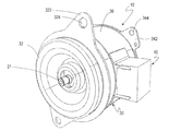
- FIG. 11 is a perspective view showing a motor 10 provided with a neutralizer 40 according to an exemplary embodiment.
- FIG. 12 is a plan view of the motor 10 when viewed from a direction parallel to the rotation axis of the motor 10.
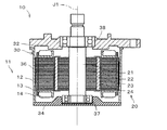
- FIG. 13 is a cross-sectional view of the motor 10 according to an exemplary embodiment.
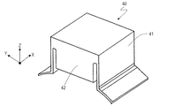
- FIG. 14A is a perspective view of the neutralizer 40 according to an exemplary embodiment.
- FIG. 14B is a plan view of the neutralizer 40 according to the exemplary embodiment.
- FIG. 15 is a plan view of the neutralizer 40 having another structure when viewed from a direction parallel to the rotation axis of the motor 10.
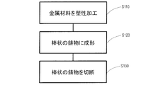
- FIG. 16 is a flowchart showing a manufacturing process according to the first manufacturing method according to an exemplary embodiment.
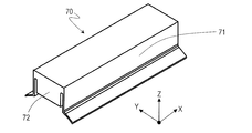
- FIG. 17 is a perspective view of the rod-shaped neutralizer 70 according to the exemplary embodiment.
- FIG. 18 is a diagram showing how a plurality of neutralizers 40 can be obtained from a rod-shaped neutralizer 70.
- FIG. 19 is a flowchart showing a manufacturing process according to a second manufacturing method according to an exemplary embodiment.
- FIG. 20 is a flowchart showing a manufacturing process according to a third manufacturing method according to an exemplary embodiment.
- FIG. 21A is a diagram showing the dimensions of the outer cover 41 and the inner mass 42 in the y and z directions, respectively.
- FIG. 21B is a diagram showing the dimensions of the outer cover 41 in the x direction.
- FIG. 22 is a graph showing the analysis result of the vibration reduction effect by the finite element method.
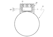
- FIG. 23 is a plan view of the motor 10 including the power connector 50 when viewed from a direction parallel to the rotation axis of the motor 10.
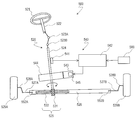
- FIG. 24 is a diagram schematically showing an electric power steering device 500 according to an exemplary embodiment.
- a neutralizer is used in order to reduce the vibration transmitted from the motor to the vehicle body.
- the neutralizer generates a reflected wave that is 180 degrees out of phase due to substantially total internal reflection with respect to vibration (input wave) that is a noise source, and superimposes it on the input wave. Thereby, the vibration can be canceled.
- the path from the vibration (input) generated from the motor to the noise (output) in the vehicle body is expressed by using the transfer function.
- the motor that can be changed as a motor maker is defined as an active part, and the part other than the motor of the vehicle that cannot be changed as a motor maker is distinguished as a passive part. Then, under the condition that the dichotomy of the active part and the passive part is rigidly coupled, the vibration of the entire system consisting of the active part and the passive part is reduced by making a structural change only to the active part. Let me. In the present embodiment, the vibration of the entire system at the target frequency is reduced without deteriorating with respect to any passive part within the constraint that only the active part can be structurally changed.
- FIG. 1 is a free body diagram of an active part and a passive part according to this embodiment.
- the degree of freedom of vibration and the degree of freedom of response evaluation in the entire system are shown by “1" and "4" on the left side of FIG. 1, respectively.
- the right side of FIG. 1 shows a free body diagram in which the entire system is divided into two systems.
- the degree of freedom of vibration is on the active part side (motor), and the degree of freedom of response evaluation is on the passive part side (vehicle body).
- the degree of freedom of connection between the active part side and the passive part side is indicated by "2" and "3", respectively.
- the basic equation (1) of the transfer function synthesis method in this division is as shown below.
- F 1 A is the force given to the system.
- X 4 AB is the displacement of the response evaluation degree of freedom 4 in the passive part B when the force F 1 A is applied to the vibration degree of freedom 1 in the active part A, and is expressed in the frequency domain.
- H is compliance (frequency response function), and the number on the left side of the subscript represents the number of degrees of freedom on the response side, and the number on the right side represents the number of degrees of freedom on the vibration side.
- a and B on the right shoulder indicate that the amount is related to the system A and B, and in the case of AB, it indicates that the amount is related to the entire system consisting of the system A and the system B.
- H 22 A is a vibration transfer point transfer function of the attachment portion of the motor to the automobile.
- H 21 A is a transfer function from the vibration source of the motor to the joint between the motor and the automobile.
- (H 22 A + H 33 B ) -1 in the equation (1) is the kernel (kernel) dynamic rigidity.
- H 22 A + H 33 B is called kernel compliance.
- the kernel dynamic stiffness is a dynamic stiffness matrix of the coupling part of the dichotomous system, and includes the characteristics of the entire system.
- the kernel dynamic rigidity is physically an amount considered to be an amplification factor when the displacement of the coupling portion is converted into the transmission force which is the internal force of the coupling portion. It can be seen that the entire system resonates when this amplification factor becomes infinite. That is, assuming that the degree of freedom of the coupling portion is N, the entire system generally resonates when the condition of the following equation (2) is satisfied.
- the vibration of the entire system can be reduced by taking measures against vibration only on the active part side in the above dichotomized system by utilizing this property of kernel compliance.
- FIG. 2 shows the frequency response functions of the active part and the passive part.
- FIG. 2 shows the relationship of the transfer function as the relationship between the actual motor (active part) and the automobile (passive part).
- the motor (active part) is much smaller than the automobile (passive part) and has a rigid structure compared to the vehicle body. Therefore, in the band of several hundred Hz where the vibration and noise of the motor become a problem, the compliance of the active part is governed by the rigid body mode, and the vibration mode does not exist.
- the coupling portion is a multi-degree-of-freedom coupling
- the dominant degree of freedom of the transmitting force involved in the resonance of the entire system is a decimal degree of freedom. Therefore, even if the design is made assuming that about 1 to 2 degrees of freedom is dominant, resonance countermeasures can be taken.
- the kernel dynamic rigidity which is the reciprocal of the kernel compliance, becomes infinite, and the whole system resonates in the same state as when a coupling spring with an infinite spring constant is displaced.
- H 33 B and H 43 B actually correspond to automobile parts other than the motor, it is difficult to make changes from the standpoint of the motor manufacturer.
- the changes can be made to H 22 A (excitation point transfer function of the motor mounting part to the vehicle) and H 21 A (transfer function from the vibration source of the motor to the joint between the motor and the vehicle). ).
- the degree of freedom of evaluation can be reduced. As described above, the inventor of the present application has found that bringing the value of H 21 A ( ⁇ t ) close to 0 is an effective vibration reduction method that can be adopted by motor manufacturers.
- the motor is provided with a characteristic that the transfer function H 21 A ( ⁇ t ) in the system from the vibration source of the motor to the joint between the motor and the vehicle body suppresses the vibration of the joint at the target frequency.
- a neutralizer Provide a neutralizer.
- Virtual grounding means setting the frequency response to zero.
- each of the mass point and the spring may be two or more.
- Elements that become vibration sources in the motor are, for example, rotors, stators, bearings, etc.
- the vibration source of the motor includes an electromagnetic vibration force, mechanical vibration of the bearing portion, and the like, and it is difficult to specify the position of the vibration degree of freedom 1 in FIG.
- FIG. 2 it is certain that there is an excitation degree of freedom 1 somewhere on the active part side on the left side of the coupling degree of freedom on the active part side and the passive part side.
- a neutralizer will be installed between the degrees of freedom and the degree of freedom of connection. Then, a method of completely reflecting the wave of the target frequency generated by the degree of freedom of excitation by this neutralizer and making the value of the frequency response function theoretically 0 will be described.
- FIG. 3 is a diagram showing the concept of the neutralizer 40.
- the theory and numerical examples are shown assuming that the transmission force in the vertical direction vertically entering the vehicle body from the motor 10 is dominant. Since the longitudinal wave and the torsional wave can be expressed by the wave equation of the same form, the method of the present embodiment can be similarly applied to the case where the torsional moment around the rotation axis of the motor becomes the dominant transmitting force. Further, the method of the present embodiment can be applied even when the transmitting force in the direction related to the bending wave is dominant.
- the reflection characteristics and transmission characteristics of waves when the neutralizer 40 is regarded as a discontinuity for wave propagation will be described.
- the force applied to the motor 10 by the spring due to the movement of the neutralizer 40 can be calculated in the same manner as the dynamic vibration absorber of the two-degree-of-freedom system.
- the relationship between the spring force amplitude F N and the displacement amplitude U of the neutralizer mounting degree shown in FIG. 3 can be expressed by Eq. (6) using the mode equivalent rigidity ⁇ .
- the medium is invariant on the left and right of the position x.
- k is the wave number of this medium
- E is the Young's modulus of the neutralizer
- S is the cross-sectional area of the beam (beam) of the neutralizer, and corresponds to the cross-sectional area of the path through which the vibration energy is transmitted.
- equations (6) to (10) into these equations (11) and (12), the relationship between wave amplitudes is arranged in the form of the scattering matrix shown in equation (13).
- ⁇ ⁇ / ⁇ N.
- ⁇ is the angular frequency of the harmonic excitation force
- ⁇ N is the natural angular frequency when the neutralizer is fixed to the ground.
- ⁇ is the ratio of ⁇ N to ⁇ .
- the reflection coefficients r LR and r RL are the amplitude ratios “b L / a L ” and “b R / a R ” of the forward wave (+ x direction) and the bounce wave (backward wave ( ⁇ x direction)).
- the wave generated by the vibration is the coupling part freedom.
- the frequency response function H 21 A between two points formed by superimposing waves without reaching degrees 2 is theoretically 0 at this frequency.
- the frequency response function H 21 A can be freely set by the motor manufacturer, and the value of H 21 A can be reduced at a desired frequency.
- the installation position of the neutralizer may be between the vibration degree of freedom 1 and the joint degree of freedom 2. Therefore, the method of this embodiment is very useful for motor manufacturers who have to install the motors in the limited space of various systems.
- the target of the simulation is the longitudinal wave (longitudinal vibration) of the beam structure.
- the vibration generated by the motor is transmitted to the vehicle, and the vibration is transmitted to the panel members in the automobile, where acoustic radiation is generated, but acoustic radiation is not considered here.
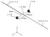
- FIGS. 4 and 5 show the system used in the simulation.
- the active part mimics a motor mounted on an automotive EPS.
- the passive part imitates parts other than the motor of an automobile.
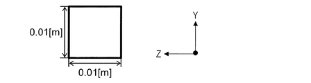
- the cross-sectional shape of the beam shall be a square with a side of 0.01 m as shown in FIG.
- the length of the active part of the beam is 0.05 m and the length of the passive part is 1.0 m.
- a neutralizer was installed in the active part.
- the vibrations of the systems shown in FIGS. 4 and 5 were obtained by finite element analysis.
- the active part was made of aluminum, and the density was 2680 kg / m 3 , Young's modulus was 7.60 ⁇ 10 10 Pa, and Poisson's ratio was 0.33.
- the mass of the active part alone was 0.0134 kg.
- the passive part was assumed to be a mild steel material, and had a density of 7930 kg / m 3 , a Young's modulus of 1.97 ⁇ 10 11 Pa, and a Poisson's ratio of 0.30.
- the mass of the passive part alone was 0.793 kg.
- the degree of freedom of vibration was given in the positive direction of x at the position marked "node: 1" in FIG.
- the degree of freedom in response evaluation was set to the positive direction of x at the position marked “node: 4” in FIG.
- the neutralizer has, for example, a spring-mass structure. As a neutralizer, two leaf springs that deform symmetrically in the x direction across the beam are installed, and a concentrated mass is bonded to each of the tips of the leaf springs.
- Each of the two leaf springs was assumed to be a phosphor bronze plate having a thickness of 0.002 m and a width of 0.01 m as shown in FIG.
- the material properties of phosphor bronze were a density of 8800 kg / m 3 , a Young's modulus of 1.10 ⁇ 10 11 Pa, and a Poisson's ratio of 0.33.
- the concentrated mass of the tips of the two leaf springs was 0.467 g for both.
- the mass of each neutralizer is 2.23 g.
- the natural frequency of the neutralizer shall be the same as the frequency of vibration (target frequency) to be reduced in the EPS to which the motor is attached.
- the natural frequency of the neutralizer is the same as the natural frequency of the steering shaft provided in the EPS.
- the natural frequency of the steering shaft is set to 2450 Hz here.
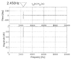
- FIG. 8 shows the compliance in the x direction at “node: 4” when “node: 1” is vibrated in the x direction.
- the horizontal axis represents frequency and the vertical axis represents phase and magnitude.
- the dashed line shows the compliance when the neutralizer is not installed, and the solid line shows the compliance when the neutralizer is installed. It can be seen that the compliance value is significantly reduced at the target frequency of 2450 Hz when the neutralizer is attached as compared with when the neutralizer is not attached.
- FIG. 9 shows the result of calculating the reflectance coefficient of the neutralizer attached to the active part with respect to the longitudinal wave according to the equation (14).
- FIG. 10 shows the result of calculating the transmission coefficient for the longitudinal wave of the neutralizer mounted on the active part according to the equation (15).
- the horizontal axis of FIGS. 9 and 10 represents frequency, and the vertical axis represents phase and magnitude.
- the reflection coefficient at the target frequency of 2450 Hz is 1, the transmission coefficient is 0, and the wave motion of 2450 Hz is blocked while propagating from the vibration degree of freedom to the coupling degree of freedom by the neutralizer attached to the active part.
- You can see (virtual ground). That is, theoretically, H 21 A 0 at the target frequency of 2450 Hz.
- FIG. 11 is a perspective view showing a motor 10 to which the neutralizer 40 is attached.
- FIG. 12 is a plan view of the motor 10 when viewed from the axial direction of the motor 10, and in particular, is a plan view schematically showing a state of the neutralizer 40 attached to the outer surface of the housing 30.
- FIG. 12 in order to avoid complicating the drawings, the illustration of the internal structure other than the neutralizer 40 is omitted, and only the outline of the motor 10 is shown.
- FIG. 13 is a cross-sectional view of the motor 10. In order to explain the inside of the motor 10 in an easy-to-understand manner, the neutralizer 40 is not shown in FIG.
- the direction parallel to the direction in which the central axis J1 of the motor 10 extends is referred to as "axial direction”.
- the direction orthogonal to the axial direction of the motor 10 is called the “diameter direction”.
- the direction along the arc centered on the central axis J1 of the motor 10 is called the “circumferential direction”.
- the shape and positional relationship of each member will be described with the axial direction as the vertical direction. However, this is defined in the drawings only for convenience of explanation, and does not limit the orientation when the motor 10 is used.
- the vibration and noise in the vehicle body of an automobile or the like caused by the motor 10 for EPS correlate with the vibration in the rotation direction of the motor 10 and the torque ripple. Therefore, in the present embodiment, vibration and noise in the vehicle body are suppressed by suppressing vibration in the rotation direction of the motor 10.
- the motor 10 in this embodiment is a so-called inner rotor type motor.
- the motor 10 includes a stator 11, a rotor 20, a housing 30, and a neutralizer 40.
- the housing 30 is a tubular member extending in the axial direction.
- the housing 30 is formed of, for example, a metal material such as aluminum (including an aluminum alloy) or SUS.
- the housing 30 houses the rotor 20 and the stator 11 inside the housing 30.
- the housing 30 has a tubular portion 36, a bottom portion 34, and a lid portion 32.
- the tubular portion 36 is a tubular member extending in the axial direction.
- the bottom portion 34 is arranged on the lower side in the axial direction of the tubular portion 36, and covers the opening on the lower side in the axial direction of the tubular portion 36.
- a lower bearing 37 is attached to the bottom 34.
- On the outer surface of the bottom portion 34 a plurality of bottom flange portions 342 extending outward in the radial direction are arranged. At least one bottom through hole 344 that penetrates in the axial direction is formed in the bottom flange portion 342.
- the lid portion 32 is arranged on the axially upper side of the tubular portion 36 and covers the opening on the axially upper side of the tubular portion 36.
- An upper bearing 38 is attached to the lid portion 32.
- the upper bearing 38 and the lower bearing 37 rotatably support the rotor 20.
- a plurality of lid flange portions 322 extending radially outward are provided on the outer surface of the lid portion 32.
- At least one lid through hole 324 that penetrates in the axial direction is formed in the lid flange portion 322.
- Either the bottom portion 34 or the lid portion 32 may be integrally formed with the tubular portion 36.
- the stator 11 includes a stator core 12, an insulator 13, and a coil 14.
- the stator core 12 is, for example, a laminated iron core in which a plurality of electromagnetic steel plates are laminated in the axial direction.
- the stator core 12 may include a partial pressure core and the like.
- the stator core 12 has an annular core back and a plurality of teeth. The plurality of teeth extend radially inward from the core back and are arranged at intervals in the circumferential direction.
- the insulator 13 is an insulator that covers the surface of the stator core 12.
- the rotor 20 is arranged inside the stator 11 in the radial direction and faces the teeth in the radial direction.
- the rotor 20 includes a shaft 21, a yoke 22, a rotor magnet 23, and a cover member 24.
- the shaft 21 extends in the axial direction about the central axis J1.
- the shaft 21 may be solid or hollow.
- the yoke 22 has a substantially cylindrical shape and is fixed to the shaft 21.
- the yoke 22 is formed by laminating, for example, thin plate-shaped magnetic steel plates.
- the rotor magnet 23 is arranged inside the stator 11 and is fixed to the outer surface of the yoke 22 by, for example, an adhesive.
- the cover member 24 covers the outside of the rotor magnet 23.
- FIG. 14A is a perspective view of the neutralizer 40.
- FIG. 14B is a plan view of the neutralizer 40 when viewed from the axial direction of the motor 10.
- FIGS. 14A and 14B show the X-axis, Y-axis, and Z-axis that are orthogonal to each other.
- the structure of the neutralizer 40 will be described with reference to these axes as appropriate.
- the neutralizer 40 can be directly or indirectly fixed at any position on the outer surface of the tubular portion 36.
- the target for fixing the neutralizer 40 is not limited to the housing 30, and may be, for example, a stator core 12 or an insulator 13.
- the neutralizer 40 may be fixed directly or indirectly to the mounting surface of the stator core 12 or insulator 13.
- the outer surface of the housing 30 includes a mounting surface. The neutralizer 40 is attached to the mounting surface of the housing 30, more specifically, the tubular portion 36.
- the neutralizer 40 is preferably fixed to the housing 30 so that the direction in which it extends is parallel to the rotation axis of the motor 10. As a result, as will be described later, it is possible to effectively cancel the vibration component in the circumferential direction generated from the motor 10.
- parallel to the rotation axis of the motor 10 means that the angle formed by the rotation axis of the motor 10 and the axis defining the direction in which the neutralizer 40 extends is within the range of, for example, 0 ° to ⁇ 5 °. Means that.
- the neutralizer 40 may be fixed to the housing 30 at an arbitrary angle with respect to the rotation axis of the motor 10.
- the neutralizer 40 is fixed perpendicular to the rotation axis of the motor 10 (that is, 90 ° with respect to the rotation axis), the axial component of vibration can be reduced.
- the neutralizer 40 will be described as a member extending parallel to the rotation axis of the motor 10.
- the neutralizer 40 includes an outer cover 41 and an inner mass 42, and has a predetermined natural frequency.
- the inner mass 42 is integrally formed with the outer cover 41 and is made of the same metal material.
- FIG. 14B shows a broken line representing a virtual boundary between the outer cover 41 and the inner mass 42 for convenience of explanation.
- the outer cover 41 is directly or indirectly fixed to the mounting surface of the housing 30 by a pair of flange portions 45 described later.
- the outer cover 41 has, for example, a substantially U-shape when viewed from the axial direction of the motor 10.
- the outer cover 41 is a member that extends in the axial direction of the motor 10 (x direction in the drawing) and internally supports the inner mass 42.
- the outer cover 41 has a lid portion 43 and a pair of wall portions 44.
- the lid portion 43 is a member that supports the inner mass 42 extending in the second direction orthogonal to the first direction and extending in the first direction.
- the pair of wall portions 44 are members extending from both ends of the lid portion 43 in a third direction orthogonal to the first direction and the second direction.
- the first direction coincides with the axial direction of the motor 10 (x direction in the figure).
- the second direction coincides with the circumferential direction of the motor 10 (y direction in the figure).
- the third direction coincides with the radial direction of the motor 10 (z direction in the figure).
- the pair of wall portions 44 has a pair of flange portions 45 that directly or indirectly fix the neutralizer 40 to the mounting surface of the housing 30. As shown in FIG. 14B, the pair of flange portions 45 extend in opposite directions along the circumferential direction of the motor 10.
- the lid portion 43 and the pair of wall portions 44 can be integrally formed as one member by pressing, cutting, casting, or the like.
- the lid portion 43 and the pair of wall portions 44 are formed of a metal material such as aluminum, aluminum alloy, copper, copper alloy, iron, or iron alloy.
- the pair of wall portions 44 may be formed of an elastic member such as a leaf spring, unlike the material of the lid portion 43.
- the pair of wall portions 44 may be formed of different materials.
- the lid 43 and the pair of wall 44s can be manufactured as separate members and the individual members can be joined together, for example, by welding or gluing.
- the outer cover 41 is fixed to the mounting surface of the housing 30 via a pair of flange portions 45 of the pair of wall portions 44 by, for example, screwing, welding, gluing, caulking, or the like.
- the pair of wall portions 44 may be integrally formed with the housing 30 by cutting or casting.
- the inner mass 42 is a member that is located inside the outer cover 41 and protrudes from the lid portion 43 toward the mounting surface (that is, the outer surface) of the housing 30. Like the outer cover 41, the inner mass 42 is a member extending parallel to the axial direction of the motor 10. The inner surfaces 44s on both sides of the pair of wall portions 44 face the side surfaces 42s of the inner mass 42 via the gaps S formed along the axial direction.
- the inner mass 42 is a substantially rectangular parallelepiped weight, but may be, for example, a cylindrical weight or a prismatic weight having a polygonal bottom surface.
- the inner mass 42 When the neutralizer 40 is viewed from the axial direction, the inner mass 42 is surrounded by a pair of wall portions 44 and the outer surfaces of the housing 30 via the gap S. When the neutralizer 40 is viewed from the outside of the motor 10, it is sufficient that at least a part of the inner mass 42 is covered by the outer cover 41.
- the inner mass 42 is from the outer cover 41 in the ⁇ x direction in the drawing. It may extend in at least one direction.
- the inner mass 42 is formed of a metal material such as aluminum, aluminum alloy, copper, copper alloy, iron, or iron alloy.
- FIG. 15 is a plan view of the neutralizer 40 having another structure when viewed from the axial direction of the motor 10.
- the outer cover 41 and the inner mass 42 may be separate members.
- the inner mass 42 is referred to as a member protruding from the lid portion 43 toward the mounting surface of the housing 30 in the present specification.
- the outer cover 41 has a groove 47 for fixing the inner mass 42
- the inner mass 42 has a protrusion 48 corresponding to the groove 47 of the outer cover 41.
- the inner mass 42 is attached to the outer cover 41 by engaging the groove 47 with the protrusion 48.
- the inner mass 42 is attached to the outer cover 41 by adhesion, welding, press fitting, caulking, or the like.
- the size, material, mass, etc. of the members constituting the neutralizer 40 are appropriately determined at the time of design using, for example, the finite element method.
- the neutralizer 40 in the plan view of FIG. 14B, has a substantially line-symmetrical shape with the center line (one-dot chain line in the drawing) penetrating the outer cover 41 and the inner mass 42 as the axis of symmetry.
- the mass which is a parameter of the vibration reduction effect of the neutralizer 40, is secured.
- the frequency domain to be reduced is determined by the natural frequency of the neutralizer 40.
- the natural frequency is determined based on the mass of the inner mass 42 and the plate thickness (more specifically, the rigidity) of the pair of wall portions 44. For example, if the size of the neutralizer 40 is increased and the mass of the inner mass 42 is increased without changing the plate thickness of the pair of wall portions 44, the natural frequency of the neutralizer 40 becomes smaller.
- the natural frequency of the neutralizer 40 is set to the same frequency as the vibration frequency (referred to as "target frequency") to be reduced in the vehicle body to which the motor 10 is attached.
- the natural frequency of the neutralizer 40 is set to the same frequency as the natural frequency of the steering shaft of the EPS.
- the outer cover 41 vibrates in the circumferential direction of the housing 30, and the inner mass 42 vibrates in substantially the same direction as the vibration direction of the outer cover 41. .. More specifically, the pair of wall portions 44, which are directly or indirectly fixed to the outer surface of the housing 30, extend radially inward from the lid portion 43 of the outer cover 41. Therefore, when vibration of a predetermined frequency is transmitted from the housing 30 to the pair of wall portions 44 while the motor 10 is being driven, the pair of wall portions 44 move in the circumferential direction of the housing 30 (the y direction shown in FIG. 14B). Start vibrating.
- the lid portion 43 also starts vibration in the circumferential direction in synchronization with the vibration, and repeats translation in the circumferential direction.
- the inner mass 42 repeats translation in the circumferential direction in synchronization with the lid portion 43.
- the neutralizer 40 is attached to the outer surface of the housing 30. According to the configuration of the neutralizer 40, the inner mass 42 can be vibrated in the circumferential direction. As a result, the amount of canceling the vibration component in the rotation direction of the motor 10 is amplified, and as a result, the vibration component in the circumferential direction can be effectively canceled.
- Circumferential vibration generated from the motor 10 is transmitted to the neutralizer 40 and reduced. As a result, vibration in the rotation direction of the motor 10 is suppressed, and as a result, noise transmitted to the driver of the automobile or the like can be suppressed.
- the neutralizer 40 can be manufactured by various manufacturing methods. Hereinafter, examples of the first to third manufacturing methods will be described.
- FIG. 16 is a flowchart showing a manufacturing process according to the first manufacturing method.
- FIG. 17 is a perspective view of the rod-shaped neutralizer 70.
- the X-axis, Y-axis, and Z-axis that are orthogonal to each other are shown as in FIG. 14A.
- FIG. 18 is a diagram showing how a plurality of neutralizers 40 can be obtained from a rod-shaped neutralizer 70.
- the outer cover 41 and the inner mass 42 can be integrally formed.
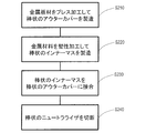
- the first manufacturing method includes a step S110 for plastically processing a metal material, a step S120 for forming a rod-shaped casting, and a step S130 for cutting a rod-shaped casting.
- a metal material such as billet or bloom is plastically processed (also referred to as "hot processing") using a mold, and the casting is formed into a rod shape.
- a rod-shaped casting is manufactured.
- Iron, copper, aluminum, or the like can be used as the metal material.
- plastic working includes methods such as hot extrusion, conform extrusion, hot forging or hot rolling.
- a semi-finished product such as billet or bloom can be manufactured from a metal material, and the semi-finished product can be formed by hot rolling to produce a rod-shaped casting.
- rod-shaped castings can be produced by using a combination of punching and laminating, liquid forging or powder metallurgy.
- the rod-shaped casting is the rod-shaped neutralizer 70 shown in FIG.
- the rod-shaped neutralizer 70 has a rod-shaped outer cover 71 and a rod-shaped inner mass 72.
- the rod-shaped inner mass 72 is integrally formed with the rod-shaped outer cover 71.
- the rod-shaped outer cover 71 and the rod-shaped inner mass 72 may be manufactured as separate members.
- the rod-shaped neutralizer 70 is a member extending in the x direction of FIG. At any position along the x-direction, the cross section of the neutralizer 70 cut along the plane perpendicular to the x-direction (yz plane of FIG. 17) has the same shape as the shape in the plan view shown in FIG. 14B.
- a rod-shaped casting that is, a rod-shaped neutralizer 70 is cut to obtain a plurality of neutralizers 40 shown in FIG. More specifically, the length (dimensions) of the neutralizer 40 in the x direction is determined in consideration of the frequency range of vibration to be reduced, the shape and size of the motor, and the like. By cutting the rod-shaped neutralizer 70 to that size, the neutralizer 40 in which the outer cover 41 and the inner mass 42 are integrally formed can be manufactured.
- the rod-shaped neutralizer 70 may be divided into a plurality of parts to produce a plurality of neutralizers 40 having different lengths, or two types of neutralizers 40 having different lengths may be produced.
- the first manufacturing method relatively complicated processes such as welding, adhesion, and press-fitting for attaching the inner mass 42 to the outer cover 41 are not required. This makes it possible to easily manufacture the neutralizer 40 in which the outer cover 41 and the inner mass 42 are integrally formed. As described above, the first manufacturing method is advantageous in that the effect of reducing the manufacturing man-hours and the manufacturing cost can be obtained.
- FIG. 19 is a flowchart showing a manufacturing process according to the second manufacturing method.
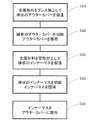
- the second manufacturing method includes a step S210 for manufacturing the rod-shaped outer cover 71, a step S220 for manufacturing the rod-shaped inner mass 72, a step S230 for joining the rod-shaped inner mass 72 to the rod-shaped outer cover 71, and a rod-shaped inner mass 72.
- the rod-shaped outer cover 71 and the rod-shaped inner mass 72 can be manufactured using the same metal material such as iron, copper or aluminum.
- step S210 a metal plate material such as iron, copper, or aluminum is press-processed to manufacture a rod-shaped outer cover 71 having a U-shaped cross-sectional shape.
- a metal material such as billet or bloom is plastically processed (for example, hot extruded) using a mold to form a rod shape, and a rod-shaped inner mass 72 is manufactured.
- a semi-finished product such as billet or bloom is manufactured from a metal material by combining continuous casting and hot rolling, and the semi-finished product is formed by hot rolling to form a rod-shaped inner.
- Mass 72 can be manufactured.
- step S230 the rod-shaped neutralizer 70 shown in FIG. 17 is manufactured by joining the rod-shaped inner mass 72 to the rod-shaped outer cover 71 by adhesion, welding, press-fitting, caulking, or engaging.
- step S240 a plurality of neutralizers 40 are obtained by cutting the rod-shaped neutralizer 70.
- the second manufacturing method is advantageous in that the effect of reducing the manufacturing man-hours and the manufacturing cost can be obtained as in the first manufacturing method.
- FIG. 20 is a flowchart showing a manufacturing process according to the third manufacturing method.
- the third manufacturing method includes a step S310 for manufacturing the rod-shaped outer cover 71, a step S320 for cutting the rod-shaped outer cover, a step S330 for manufacturing the rod-shaped inner mass 72, and a step for cutting the rod-shaped inner mass. Includes S340 and step S350 of joining the inner mass 42 to the outer cover 41.
- step S310 the metal plate material is press-processed to manufacture a rod-shaped outer cover 71 having a U-shaped cross-sectional shape.
- step S320 the rod-shaped outer cover 71 is cut to obtain a plurality of outer covers 41.
- a metal material such as billet or bloom is plastically processed (for example, hot extruded) using a mold to form a rod shape, and a rod-shaped inner mass 72 is manufactured.
- a semi-finished product such as billet or bloom is manufactured from a metal material by combining continuous casting and hot rolling, and the semi-finished product is formed by hot rolling to form a rod-shaped inner.
- Mass 72 can be manufactured.
- the rod-shaped inner mass 72 is cut to obtain a plurality of inner masses 42.
- step S350 the neutralizer 40 is obtained by joining the inner mass 42 to the outer cover 41 by adhesion, welding, press fitting, caulking, engagement, or the like.
- the neutralizer 40 can be easily manufactured.
- the neutralizer 40 can be manufactured by using any of the first to third manufacturing methods, and the neutralizer 40 can be attached to the housing 30 of the motor 10 to manufacture the motor 10 including the neutralizer 40. ..
- the inventor of the present application analyzed the vibration reduction effect of the neutralizer 40 according to the present embodiment by using the finite element method. In the analysis, a moment load was applied to the side surface of a hollow cylinder simulating a motor.
- the analysis conditions by the finite element method are described below.
- Tool used ANSYS Workbench; Analysis method: Frequency response analysis (full analysis); Analysis range 0 to 1800 [Hz]; Resolution: 180; Load method: z-axis on the outer circumference of the motor housing (corresponding to the rotation axis in the specification) Gives a moment of 1 [Nm] about the axis; Response point: Rotational direction of a node on the outer circumference of the motor housing; Mass / node / element of the motor housing: 490 [g] / 14263/7126; Material properties: Density (7900 [kg / m 3 ]), Young ratio (2.09E + 11 [Pa]), Poisson's ratio (0.3).
- the neutralizer 40 was fixed to the motor housing with a bond connection.
- bond represents a state in which slipping / separation does not occur between faces or sides.
- the area of the bond connection can be considered to be in a bonded state.
- the target frequency was set to 800 Hz. Therefore, the natural frequency of the neutralizer 40 is set to 800 Hz.
- 21A and 21B show the dimensions of the outer cover 41 and the inner mass 42 in the x, y and z directions, respectively.
- the length a of the outer cover 41 shown in FIG. 21A in the y direction is 29.7 mm.
- the length b of the inner mass 42 in the y direction is 25.4 mm.
- the thickness c of each of the pair of wall portions 44 in the y direction is 1.15 mm.
- the lengths d and e of the pair of wall portions 44 in the z direction are 23.4 mm and 18.0 mm, respectively.
- the length f of each of the outer cover 41 and the inner mass 42 in the y direction is 30.0 mm.
- the mass of the neutralizer 40 is 139 [g].
- the physical properties of the material are density: 7900 [kg / m 3 ], Young's modulus: 2.09E + 11 [Pa], and Poisson's ratio: 0.3.
- FIG. 22 is a graph showing the analysis result of the vibration reduction effect by the finite element method.
- the vertical axis of the graph shows the displacement amplitude [dB] in the motor rotation direction, and the horizontal axis shows the frequency [Hz].
- the graph also shows the analysis results of a single motor without the neutralizer 40. As shown in the analysis results, by attaching the neutralizer of the present disclosure to the motor, it was confirmed that the vibration reduction effect of about 32 dB at the target frequency: 800 Hz was confirmed as compared with the motor alone.
- only one neutralizer 40 is attached to the housing 30 of the motor 10.
- the number of neutralizers 40 is not limited to one, and a plurality of neutralizers 40 may be attached to the motor 10.
- a plurality of neutralizers 40 may be arranged side by side in the axial direction or may be arranged at intervals in the circumferential direction.
- the neutralizer 40 is not only fixed to the tubular portion 36, but at least a part thereof may be fixed to the lid portion 32, the bottom portion 34, or the like. Further, the neutralizer 40 may be fixed to the stator core 12 or the insulator 13 as described above.
- a cover member (not shown) that covers the neutralizer 40 may be attached to the outer surface of the housing 30. By covering the neutralizer 40 with the cover member, it is possible to prevent the neutralizer 40 from being damaged or deformed when the motor 10 after the neutralizer 40 is attached is conveyed.
- the cover member may cover the entire neutralizer 40 or only a part of the neutralizer 40.
- the cover member is directly or indirectly fixed to the tubular portion 36 by a method such as welding, bonding, caulking, or screwing.
- the motor 10 is mounted on an automobile, for example, and is used to generate a driving force for EPS.
- the motor 10 may be used for other known applications.
- the motor 10 may be used as a drive source for other parts of the vehicle, such as an engine cooling fan.
- the motor 10 may be mounted on home appliances, OA equipment, medical equipment and the like to generate various driving forces.
- the neutralizer of the present disclosure can be attached to any device (for example, a generator) that may have a vibration source other than a motor. Like the motor, it is expected to be able to reduce vibration at the target frequency. In that case, the neutralizer can reduce the vibration of a predetermined frequency in the second device to which the first device having the vibration source is attached.
- the first device are motors, generators, engines, fans, pumps or compressors and the like.
- the second device include electric assisted bicycles, motorbikes, mobility such as automobiles, home appliances such as washing machines and air conditioners including outdoor units, servers with fans, machine tools, robots, personal computers, home appliances, etc. It is a general house to be installed, or a factory where machine machines, compressors, etc. are installed.
- the neutralizer in one aspect of the present disclosure may be part of a power connector.
- an EPS motor includes a power connector on the outer surface of the housing, which is used to supply power from the outside.
- the power connector is connected to an external power supply by a harness, and drive power is supplied to the motor.
- FIG. 23 is a plan view of the motor 10 including the power connector 50 when viewed from the axial direction of the motor 10, and in particular, schematically shows the structure of the power connector 50.
- the motor 10 further includes a power connector 50.
- the power connector 50 has an outer cover 41, an inner mass 42, and a plurality of power terminals 51.
- the neutralizer 40 can be a part of the power connector 50. For example, by changing the shape of the conventional resin cover member that protects the power supply terminal 51 to the same shape as the outer cover 41 of the neutralizer 40, a power connector 50 that also serves as the neutralizer and the power supply terminal can be obtained.
- At least a portion of the neutralizer 40 of the power connector 50 is formed of, for example, the same metal material as the neutralizer 40 described above.
- each member may be made of different materials.
- the cover member that protects the power supply terminal 51 may be formed of, for example, a resin material. The individual members can be joined together, for example by welding or gluing.
- the power supply terminal 51 is pulled out from the housing 30 in the radial direction, bent 90 °, and extended in the axial direction.
- the outer cover 41 is provided with a through hole through which the power supply terminal 51 is passed in the axial direction. Then, the outer cover 41 is attached to the outer surface of the housing 30 from the outer side in the radial direction. It is preferable that the conductive portion such as the power supply terminal 51 exposed from the through hole of the outer cover 41 is covered with an insulating resin or the like. In this way, the neutralizer 40 and the power supply terminal 51 can be integrated. As a result, the neutralizer can be attached to the motor without increasing the number of parts and the mounting area.
- the material of the part of the neutralizer 40 is not limited to the metal material, and may be another material.
- the material of the outer cover 41 may be the same as the cover member that protects the power supply terminal 51.
- EPS generates an auxiliary torque for assisting the steering torque of the steering system generated by the driver operating the steering wheel.
- the auxiliary torque is generated by the auxiliary torque mechanism, and the burden on the driver's operation can be reduced.
- the auxiliary torque mechanism includes a steering torque sensor, an ECU (Electronic Control Unit), a motor, a deceleration mechanism, and the like.
- the steering torque sensor detects the steering torque in the steering system.
- the ECU generates a drive signal based on the detection signal of the steering torque sensor.
- the motor 10 generates an auxiliary torque according to the steering torque based on the drive signal, and transmits the auxiliary torque to the steering system via the reduction mechanism.
- FIG. 24 schematically shows a typical configuration of the electric power steering device (EPS) 500 according to the present embodiment.
- the EPS 500 includes a steering system 520 and an auxiliary torque mechanism 540.
- the steering system 520 is, for example, a steering handle 521, a steering shaft 522 (also referred to as a "steering column"), a free shaft joint 523A, 523B, and a rotating shaft 524 (also referred to as a "pinion shaft” or an “input shaft”). ), Rack and pinion mechanism 525, rack axle 526, left and right ball joints 552A, 552B, tie rods 527A, 527B, knuckles 528A, 528B, and left and right steering wheels (for example, left and right front wheels) 529A, 259B.
- the steering handle 521 is connected to the rotating shaft 524 via the steering shaft 522 and the universal shaft joints 523A and 523B.
- a rack shaft 526 is connected to the rotating shaft 524 via a rack and pinion mechanism 525.
- the rack and pinion mechanism 525 has a pinion 531 provided on the rotating shaft 524 and a rack 532 provided on the rack shaft 526.
- a right steering wheel 529A is connected to the right end of the rack shaft 526 via a ball joint 552A, a tie rod 527A, and a knuckle 528A in this order.
- the left steering wheel 529B is connected to the left end of the rack shaft 526 via a ball joint 552B, a tie rod 527B, and a knuckle 528B in this order.
- the right side and the left side correspond to the right side and the left side as seen from the driver sitting in the seat, respectively.
- steering torque is generated when the driver operates the steering handle 521, and is transmitted to the left and right steering wheels 529A and 259B via the rack and pinion mechanism 525.
- the driver can operate the left and right steering wheels 529A and 529B.
- the auxiliary torque mechanism 540 includes, for example, a steering torque sensor 541, an ECU 542, a motor 543, a speed reduction mechanism 544, and a power conversion device 545.
- the auxiliary torque mechanism 540 applies auxiliary torque to the steering system 520 from the steering handle 521 to the left and right steering wheels 529A and 259B.
- the auxiliary torque is sometimes referred to as "additional torque".
- the motor 10 As the motor 543, the motor 10 provided with the above-mentioned neutralizer 40 can be used.
- the steering torque sensor 541 detects the steering torque of the steering system 520 applied by the steering handle 521.
- the ECU 542 generates a drive signal for driving the motor 543 based on a detection signal (hereinafter, referred to as “torque signal”) from the steering torque sensor 541.
- the motor 543 generates an auxiliary torque according to the steering torque based on the drive signal.
- the auxiliary torque is transmitted to the rotating shaft 524 of the steering system 520 via the reduction mechanism 544.
- the reduction mechanism 544 is, for example, a worm gear mechanism. Auxiliary torque is further transmitted from the rotating shaft 524 to the rack and pinion mechanism 525.
- the EPS 500 can be classified into a pinion assist type, a rack assist type, a column assist type, and the like, depending on where the auxiliary torque is applied to the steering system 520.
- FIG. 24 illustrates a pinion-assisted electric power steering device 500.
- the electric power steering device 500 may be a rack assist type, a column assist type, or the like.
- the external device 560 is, for example, a vehicle speed sensor.
- the external device 560 may be another ECU capable of communicating with an in-vehicle network such as CAN (Control Area Network).
- the microcontroller of the ECU 542 can vector-control or PWM-control the motor 543 based on a torque signal, a vehicle speed signal, or the like.
- the ECU 542 sets the target current value at least based on the torque signal. It is preferable that the ECU 542 sets the target current value in consideration of the vehicle speed signal detected by the vehicle speed sensor and further in consideration of the rotation signal of the rotor detected by the angle sensor.
- the ECU 542 can control the drive signal of the motor 543, that is, the drive current so that the actual current value detected by the current sensor (not shown) matches the target current value.
- the left and right steering wheels 529A and 529B can be operated by the rack shaft 526 using the combined torque obtained by adding the auxiliary torque of the motor 543 to the steering torque of the driver.
- the motor 10 provided with the neutralizer 40 for the motor 543 it is possible to reduce the vibration of the target frequency at the coupling portion between the motor and the EPS (for example, the coupling portion between the motor 543 and the reduction mechanism 544). it can. As a result, noise in the vehicle can be reduced.
- the embodiments of the present disclosure can be widely used in various devices including various motors, such as electric power steering devices, vacuum cleaners, dryers, ceiling fans, washing machines, and refrigerators.
Landscapes
- Engineering & Computer Science (AREA)
- Chemical & Material Sciences (AREA)
- Combustion & Propulsion (AREA)
- Transportation (AREA)
- Mechanical Engineering (AREA)
- Power Engineering (AREA)
- Motor Or Generator Frames (AREA)
Abstract
本開示のモータは、所定の固有振動数を有するニュートラライザを備える。ニュートラライザは、アウターカバー、およびアウターカバーの内側に位置し、第1方向に延びるインナーマスを有する。アウターカバーは、第2方向に延び、インナーマスを支持する蓋部と、蓋部の両端から第3方向に延びる一対の壁部とを有する。インナーマスは、蓋部から突き出た部材である。一対の壁部の両側の内面はそれぞれ、第1方向に沿って形成された間隙を介してインナーマスの側面に対向している。ロータの回転に応じて、モータには所定の周波数の振動が発生し、モータの振動源からモータと装置との結合部までの系は、所定の固有振動数における結合部の振動を抑制する特性を備えた伝達関数を有する。
Description
本開示は、モータ、ニュートラライザ、電動パワーステアリング装置およびニュートラライザの製造方法に関し、特に、電動モータが取り付けられた装置において発生する振動を低減する技術に関する。
自動車のパワーステアリングのアシスト機構の1つとして、電動パワーステアリングシステム(Electric Power Steering、以下EPSと称する場合がある)がある(例えば、特開2007-314070号公報を参照)。EPSを採用することにより、車両の軽量化および燃費向上を図ることができる。
しかしながら、このEPSの動力源である電動モータ(以下モータと称する場合がある)の起振力によって励起された波動が車体を伝播し、固体音となって自動車内の運転者の耳に騒音として聞こえる場合がある。例えば、低速走行時に大きくハンドル操作を行う場合、および駐車時に停車したままステアリング操作を行う場合に、そのような騒音が聞こえる頻度が増える傾向にある。
振動の解析方法として、例えば、[城戸一郎、末岡淳男、“2つの分系が強く連成する振動系の解析法”、日本機械学会論文集(C編), Vol.71、 No.712 (2005)、 pp.3335-3342]は、2つの分系の振動の連成関係を解析する手法を提案している。
城戸一郎、末岡淳男、"2つの分系が強く連成する振動系の解析法"、日本機械学会論文集(C編), Vol.71、 No.712 (2005)、 pp.3335-3342
上記のような騒音の対策を技術的に考えた場合、加振点インピーダンスの大小に影響するモータが取り付けられるステアリングユニットに対する対策、および実際に音響的な放射を生じている自動車のパネル部材に対する対策が有効と考えられる。
しかし、モータ・メーカの立場で騒音の対策を講じる場合、上記のような対策を講じることは困難である。モータ・メーカの研究により、騒音発生のメカニズムを解明でき、モータ以外の自社の担当範囲外の部材への対策が最も効率的と判断したとしても、モータ以外への対策を提案する事は困難である。
また、自動車の車体は、高モード密度の構造物であり、そのロバスト性の低さなどから、個々の車体で振動特性が大きく異なるが、自社のモータへの構造変更だけで、任意の車体に効果的な対策を求められるという難しさがある。さらに、モータはステアリングユニットに剛結合されるために、モータと自動車の車体は強連成の状態にあり、振動低減に適切な構造変更を効率的に検討することは一般に困難である。
モータに対策を施すことにより、様々な振動特性を有する任意の自動車に対して、その全系の振動・騒音を低減することが求められている。
本開示のモータは、非限定的で例示的な実施形態において、装置に取り付けられるモータであって、ステータと、前記ステータに対して相対的に回転可能なロータと、前記ロータの回転の中心軸に平行に延びる筒形状を有し、前記ステータおよび前記ロータを内部に収納するハウジングと、所定の固有振動数を有するニュートラライザと、を備え、前記ニュートラライザは、固定する対象の取り付け面に直接または間接的に固定されたアウターカバーと、前記アウターカバーの内側に位置し、第1の方向に延びるインナーマスと、を有し、前記アウターカバーは、前記第1の方向に直交する第2の方向に延び、かつ、前記インナーマスを支持する蓋部と、前記蓋部の両端から、前記第1の方向および前記第2の方向に直交する第3の方向に延びる一対の壁部と、を有し、前記インナーマスは、前記蓋部から前記取り付け面に向けて突き出た部材であり、前記一対の壁部の両側の内面はそれぞれ、前記第1の方向に沿って形成された間隙を介して前記インナーマスの側面に対向しており、前記ロータの回転に応じて、前記モータには所定の周波数の振動が発生し、前記モータの振動源から前記モータと前記装置との結合部までの系は、前記所定の固有振動数における前記結合部の振動を抑制する特性を備えた伝達関数を有する。
本開示のニュートラライザは、非限定的で例示的な実施形態において、振動源を有する第1装置が取り付けられる第2装置における所定の周波数の振動を低減させるニュートラライザであって、前記第1装置の取り付け面に直接または間接的に固定されるアウターカバーと、前記アウターカバーの内側に位置し、第1の方向に延びるインナーマスと、前記所定の周波数に相当する所定の固有振動数と、を備え、前記アウターカバーは、前記第1の方向に直交する第2の方向に延び、かつ、前記インナーマスを支持する蓋部と、前記蓋部の両端から、前記第1の方向および前記第2の方向に直交する第3の方向に延びる一対の壁部と、を有し、前記インナーマスは、前記蓋部から前記第3の方向に突き出た部材であり、前記一対の壁部の両側の内面はそれぞれ、前記第1の方向に沿って形成された間隙を介して前記インナーマスの側面に対向しており、前記第1装置の振動源から前記第1装置と前記第2装置との結合部までの系は、前記所定の固有振動数における前記結合部の振動を抑制する特性を備えた伝達関数を有する。
本開示の実施形態によれば、モータに対策を施すことにより、モータが取り付けられる装置の振動を低減させることができる。
以下、添付の図面を参照しながら、本開示の振動低減方法、モータ、ニュートラライザ、電動パワーステアリング装置および当該ニュートラライザの製造方法の実施形態を詳細に説明する。但し、必要以上に詳細な説明は省略する場合がある。例えば、既によく知られた事項の詳細説明や実質的に同一の構成に対する重複説明を省略する場合がある。これは、以下の説明が不必要に冗長になるのを避け、当業者の理解を容易にするためである。
(実施形態1)
本実施形態では、モータから車両本体へ伝わる振動を低減させるために、ニュートラライザ(Neutralizer)を用いる。ニュートラライザは、騒音源となる振動(入力波)に対して、実質的な全反射によって位相が180度ずれた反射波を生成し、入力波に重畳する。これにより、振動を打ち消すことができる。
本実施形態では、モータから車両本体へ伝わる振動を低減させるために、ニュートラライザ(Neutralizer)を用いる。ニュートラライザは、騒音源となる振動(入力波)に対して、実質的な全反射によって位相が180度ずれた反射波を生成し、入力波に重畳する。これにより、振動を打ち消すことができる。
本実施形態では、モータから発生する振動(入力)が、車体における騒音(出力)として発生するまでの経路を、伝達関数を用いて表現する。まず、実施形態に係る伝達関数合成法に基づく振動低減方法を説明する。
上述したように、モータ・メーカの立場で騒音の対策を講じる場合、モータ以外の自社の担当範囲外の部材への対策を提案する事は困難である。本実施形態では、モータ・メーカとして変更できるモータをアクティブ・パート(Active Part)とし、モータ・メーカとして変更できない車両のモータ以外の部分をパッシブ・パート(Passive Part)として区別する。そして、アクティブ・パートおよびパッシブ・パートの2分系が剛結合されるという条件下で、アクティブ・パートのみに構造変更を加える事により、アクティブ・パートとパッシブ・パートから成る全系の振動を低減させる。本実施形態では、アクティブ・パートのみしか構造変更できないという制約の中で、ターゲット周波数における全系の振動を、任意のパッシブ・パートに対して悪化させることなく低減させる。
(伝達関数合成法に基づく振動低減方法)
モータを備える自動車を、モータとそれ以外の部分の2分系に分割し、振動的な連成関係を解析する。[城戸一郎、末岡淳男、“2つの分系が強く連成する振動系の解析法”、日本機械学会論文集(C編), Vol.71、 No.712 (2005)、 pp.3335-3342]は、伝達関数合成法に基づき、カーネル動剛性行列を指標として2分系の振動的な連成関係を解析する手法を開示している。
モータを備える自動車を、モータとそれ以外の部分の2分系に分割し、振動的な連成関係を解析する。[城戸一郎、末岡淳男、“2つの分系が強く連成する振動系の解析法”、日本機械学会論文集(C編), Vol.71、 No.712 (2005)、 pp.3335-3342]は、伝達関数合成法に基づき、カーネル動剛性行列を指標として2分系の振動的な連成関係を解析する手法を開示している。
図1は、本実施形態に係るアクティブ・パートとパッシブ・パートの自由体図である。全系での加振自由度と応答評価自由度を図1の左側にそれぞれ“1”と“4”で示している。図1の右側は、全系を2分系に分割した自由体図を示している。加振自由度はアクティブ・パート側(モータ)にあり、応答評価自由度はパッシブ・パート側(車体)にある。アクティブ・パート側とパッシブ・パート側の結合自由度をそれぞれ“2”、“3”で示している。この分割における伝達関数合成法の基礎式(1)は以下に示すとおりである。

ここで、F1
Aは系に与える力である。X4
ABは、アクティブ・パートAにおける加振自由度1に力F1
Aを与えたときの、パッシブ・パートBにある応答評価自由度4の変位であり、周波数領域で表現している。Hはコンプライアンス(周波数応答関数)であり、下添字の左側の数字は応答側の自由度の番号を表し、右側の数字は加振側の自由度の番号を表している。右肩のA、Bは、分系A、Bに関係する量であることを示しており、ABとある場合は分系Aと分系Bからなる全系に関係する量であることを示している。例えば、H22
Aは、モータの自動車への取り付け部の加振点伝達関数である。H21
Aは、モータの振動源からモータと自動車との結合部までの伝達関数である。
次に、共振形成条件を説明する。式(1)のうちの(H22
A+H33
B)-1は、カーネル(kernel)動剛性である。H22
A+H33
Bは、カーネルコンプライアンス(kernel compliance)と呼ばれる。カーネル動剛性は、2分系の結合部の動剛性行列であり、全系の特性を含んでいる。カーネル動剛性は、物理的には、結合部の変位が結合部の内力である伝達力へ変換される際の増幅率と考えられる量である。この増幅率が無限大になるような場合に、全系が共振することがわかる。つまり、結合部の自由度をNとすると、一般的に、次式(2)の条件を満たす場合に全系が共振する。

以下、このカーネルコンプライアンスの性質を利用して、上記の2分系中のアクティブ・パート側のみに振動対策を施す事により、全系の振動を低減できることを説明する。
図2は、アクティブ・パートとパッシブ・パートの周波数応答関数を示している。図2は、伝達関数の関係を実際のモータ(アクティブ・パート)と、自動車(パッシブ・パート)との関係として示している。モータ(アクティブ・パート)は、自動車(パッシブ・パート)と比較して非常に小さく、車体に比べて剛な構造である。そこで、モータの振動・騒音が問題となるような数百Hzの帯域においては、アクティブ・パートのコンプライアンスは剛体モードに支配されて振動モードは存在しない。このような場合、結合部が多自由度結合であっても、全系の共振に関与する伝達力の支配的な自由度は少数自由度となる。このため、1から2自由度程度が支配的であるとして設計しても、共振対策は可能である。
そこで、ある1自由度の伝達力が支配的であるとした場合を考える。振動を低減したいターゲット周波数において、伝達力は1自由度が支配的であるとする場合に、全系応答を低減するためのアクティブ・パートの構造変更について検討する。加振自由度も応答評価自由度も1とするならば、式(1)はスカラーで表現でき、次式(3)となる。

また、式(2)に対応する全系の共振条件は次式(4)となる。

この共振条件が成り立つ周波数では、カーネルコンプライアンスの逆数であるカーネル動剛性が無限大となり、ばね定数が無限大の結合ばねに変位を与えたのと同じ状態となって、全系は共振する。
式(3)において、H33
BおよびH43
Bは、実際にはモータ以外の自動車の部分に該当する事から、モータ・メーカの立場では変更を施す事は困難である。変更を施す事ができるのは、H22
A(モータの自動車への取り付け部の加振点伝達関数)と、H21
A(モータの振動源から、モータと自動車との結合部までの伝達関数)である。
しかし、H33
Bの情報を得られない以上、モータ・メーカが式(4)の共振条件を完全に回避するのは困難である。如何にH22
Aを設計しようとも、H33
Bとの相性により、ターゲット周波数において式(4)を満たすことになれば、大きな伝達力が発生して共振してしまうことになる。しかし、通常はパッシブ・パート側に減衰がある為、共振することはない。
一方、H21
Aはモータ・メーカが自在に設計できる。このことから、ターゲット角周波数をωtとしたときに、H21
A(ωt)=0として、H21
A(ωt)F1
A(ωt)=0を実現することを考える。このとき、H43
Bが無限大の大きさにならず、式(4)の条件も満たされない限り、X4
AB(応答評価自由度4の変位)は0になることがわかる。ターゲット角周波数ωtにおける式(3)は式(5)のようになる。

この際、もしH43
Bが無限大の大きさとなる、もしくは式(4)の条件が成り立つ場合、式(5)は無限大と0の積となって、式(5)がどのような値になるかは簡単に推定できない。ただし、少なくとも、H21
A(ωt)F1
A(ωt)が大きな値を持つ場合よりも、H21
A(ωt)F1
A(ωt)=0の場合の方が、応答評価自由度を小さくできることになる。このように、本願発明者は、H21
A(ωt)の値を0に近づけることが、モータ・メーカが採れる効果的な振動低減方法であることを見出した。
(ニュートラライザ)
本実施形態では、モータの振動源からモータと車体との結合部までの系における伝達関数H21 A(ωt)が、ターゲット周波数において結合部の振動を抑制する特性を備えるように、モータにニュートラライザを設ける。
本実施形態では、モータの振動源からモータと車体との結合部までの系における伝達関数H21 A(ωt)が、ターゲット周波数において結合部の振動を抑制する特性を備えるように、モータにニュートラライザを設ける。
アクティブ・パート(モータ)へのニュートラライザの設置により、アクティブ・パートを特定周波数で仮想接地する方法を説明する。仮想接地とは、周波数応答を0にすることを意味する。アクティブ・パートを特定周波数で仮想接地することにより、理論上、加振自由度と結合自由度の間の伝達を0にすることが可能となり、周波数応答関数H21
Aの値を特定周波数で0にできる。
本明細書では、ニュートラライザと動吸振器とを区別して説明する。波動の全反射器として1つの質点と1つのばねからなる1自由度振動系を対象構造に付加する場合に、この1自由度振動系をニュートラライザと呼ぶ。特定モードの振動を低減するために、1つの質点と1つのばねからなる1自由度振動系を用いる場合に、この1自由度振動系を動吸振器と呼ぶ。なお、本明細書におけるニュートラライザでは、質点およびバネのそれぞれは2つ以上であってもよい。
モータ内の振動源となる要素は、例えばロータ、ステータ、軸受等である。一般に、モータの振動源としては電磁加振力、軸受部の機械的な振動等があり、図2中の加振自由度1の位置を特定することは難しい。しかしながら、図2において、アクティブ・パート側とパッシブ・パート側の結合自由度よりも左側のアクティブ・パート側のどこかに加振自由度1があることだけは確かであり、以下、この加振自由度と結合自由度の間にニュートラライザを設置することとする。そして、このニュートラライザにより、加振自由度で生成されたターゲット周波数の波動を完全反射して、周波数応答関数の値を理論上0にする方法を説明する。
図3は、ニュートラライザ40の概念を示す図である。本実施形態では、モータ10から車体に垂直に入る縦方向の伝達力が支配的であるとして理論と数値例を示す。縦波とねじり波は同じ形の波動方程式で表現できるため、本実施形態の方法は、モータの回転軸まわりのねじりモーメントが支配的な伝達力となる場合にも同様に適用できる。また、本実施形態の方法は、曲げ波に関係する方向の伝達力が支配的な場合にも適用できる。
ニュートラライザ40を波動伝播にとっての不連続部と見た際の波動の反射特性および透過特性を説明する。反射特性および透過特性は、ニュートラライザ取付断面(図3中のx=0の位置)における変位の連続と力のつり合いを、変位および力と波動振幅との関係を用いて解くことで求まる。ニュートラライザ40の運動に伴ってばねがモータ10に与える力は、2自由度系の動吸振器と同じように計算できる。図3中に示したばね力の振幅FNとニュートラライザ取付自由度の変位振幅Uとの関係は、モード等価剛性κを用いて式(6)で表せる。

ここで、ニュートラライザ取付断面より左側の位置xにおける変位および内力をUL(x)、FL(x)とする。ニュートラライザ取付断面より右側の位置xにおける変位および内力をUR(x)、FR(x)とする。これらを波動振幅を用いて表すと式(7)から式(10)のように表される。

ここで、位置xの左右で媒質は不変である。kはこの媒質の波数であり、Eはニュートラライザのヤング率であり、Sはニュートラライザのビーム(梁)の断面積であり、振動エネルギが伝達される通り道の断面積に該当する。位置xの左側での前進波と後退波の振幅をそれぞれaL、bLとし、位置xの右側での前進波と後退波の振幅をそれぞれaR、bRとした。このとき、ニュートラライザ取付断面(位置x=0)における変位の連続と力のつり合いは、式(11)および式(12)のように表せる。

これらの式(11)および式(12)に、式(6)から式(10)を導入して、波動振幅の関係を式(13)に示す散乱行列の形に整理する。

これにより、ニュートラライザ取付断面における縦波の反射係数および透過係数は、モード等価剛性κを用いて式(14)および式(15)のように表される。
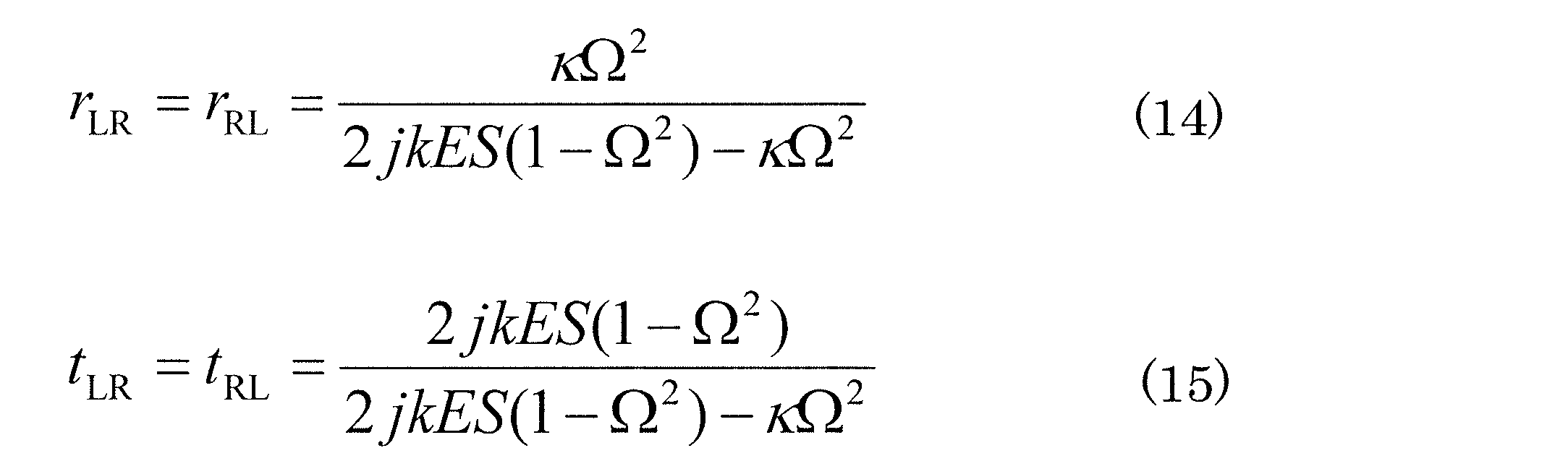
ここで、Ω=ω/ωNである。ωは調和加振力の角振動数であり、ωNはニュートラライザ単体を地面に固定した際の固有角振動数である。ΩはωNとωとの比である。
反射係数rLRおよびrRLは、前進波(+x方向)と跳ね返った波(後退波(-x方向))の振幅比“bL/aL”および“bR/aR”である。透過係数tLRおよびtRLは、x=0を基準としたプラス側とマイナス側において同じ方向を進む波同士の振幅比“aR/aL”および“bR/bL”である。
全反射となる条件は、透過係数=0、すなわち式(15)の右辺の分子が0になることである。すなわち、全反射となる条件はω=ωNであり、ニュートラライザ単体を地面に固定した際の固有振動数と調和加振力の振動数とが同じになる場合である。このとき、(1-Ω2)=0を式(14)に代入すると、反射係数rLR=rRL=-1となり、仮想的な接地、つまり伝播波動にとっての固定端と同じ状況になる。すなわち、固定端において全反射が行われ、位相が180度ずれた波が反射していくこととなる。
このように、特定の周波数の波動を完全反射する装置が、アクティブ・パートの加振自由度1と結合部自由度2の間に設置されると、加振によって生成された波動が結合部自由度2までたどり着けず、波動の重畳で形成される2点間の周波数応答関数H21
Aは、この周波数で理論上0になる。周波数応答関数H21
Aはモータ・メーカで自在に設定でき、所望の周波数でH21
Aの値を低減させることができる。
また、上記の方法において、ニュートラライザの設置位置は、加振自由度1と結合部自由度2の間であればよい。このため、モータを様々なシステムの限られたスペースに設置しなければならないモータ・メーカにとって、本実施形態の方法は非常に有用である。
(有限要素法によるシミュレーション)
ニュートラライザをモータに設けることにより、式(5)に示す応答評価自由度4の変位X4 AB(ωt)を低減できることをシミュレーションにより検証した。
ニュートラライザをモータに設けることにより、式(5)に示す応答評価自由度4の変位X4 AB(ωt)を低減できることをシミュレーションにより検証した。
シミュレーションの対象は、ビーム(梁)構造の縦波(縦振動)とする。実際にはモータが生ずる振動が車両に伝達し、その振動が自動車内のパネル部材等に伝達し、そこで音響放射を生ずる事となるが、ここでは音響放射は考慮しない。
図4および図5は、シミュレーションに用いた系を示している。アクティブ・パートは、自動車のEPSに取り付けられるモータを模している。パッシブ・パートは、自動車のモータ以外の部位を模している。
ビームの断面形状は、図6に示すように一辺が0.01mの正方形とする。ビームのアクティブ・パートの長さを0.05m、パッシブ・パートの長さを1.0mとする。アクティブ・パートにはニュートラライザを設置した。
図4および図5に示す系の振動は、有限要素解析で求めた。有限要素モデルの設定にあたり、アクティブ・パートは、アルミニウム材であるとし、密度2680kg/m3、ヤング率7.60×1010Pa、ポアソン比0.33とした。アクティブ・パート単体の質量は0.0134kgとした。パッシブ・パートは、軟鋼材であるとし、密度7930kg/m3、ヤング率1.97×1011Pa、ポアソン比0.30とした。パッシブ・パートの単体の質量は0.793kgとした。
加振自由度は、図4に“ノード:1”と記された位置のxの正方向に与えた。応答評価自由度は、図4に“ノード:4”と記された位置のxの正方向とした。H21
A(ωt)=0とするために、アクティブ・パートの“ノード:2”の位置にニュートラライザを設置した。ニュートラライザは例えばバネ-マス系の構造を有する。ニュートラライザとして、ビームを挟んで対称にx方向に変形する2枚の板ばねを設置し、それら板ばねの先端のそれぞれに集中質量を結合している。2枚の板ばねのそれぞれは、図7に示すような厚さ0.002m、幅0.01mのりん青銅板であるとした。りん青銅の材料特性として、密度8800kg/m3、ヤング率1.10×1011Pa、ポアソン比0.33とした。2枚の板ばねの先端の集中質量は、2個ともに0.467gとした。ニュートラライザの質量はそれぞれ2.23gである。ニュートラライザの固有振動数は、モータが取り付けられるEPSにおいて低減させる振動の周波数(ターゲット周波数)と同じとする。例えば、ニュートラライザの固有振動数は、EPSが備えるステアリングシャフトの固有振動数と同じとする。ステアリングシャフトの固有振動数は、ここでは2450Hzとした。
図8は、“ノード:1”をx方向に加振した際の、“ノード:4”におけるx方向のコンプライアンスを示している。横軸は周波数を表し、縦軸は位相およびマグニチュードを表している。破線はニュートラライザ未装着時のコンプライアンスを示しており、実線はニュートラライザ装着時のコンプライアンスを示している。ニュートラライザ未装着時と比較して、ニュートラライザ装着時では、ターゲット周波数である2450Hzにおいて、コンプライアンスの値は大きく低減されていることが分かる。
図9は、アクティブ・パートに装着したニュートラライザの縦波に対する反射係数を、式(14)に従って計算した結果を示している。図10は、アクティブ・パートに装着したニュートラライザの縦波に対する透過係数を、式(15)に従って計算した結果を示している。図9および図10の横軸は周波数を表し、縦軸は位相およびマグニチュードを表している。
ターゲット周波数2450Hzにおける反射係数は1、透過係数は0となっており、アクティブ・パートに装着したニュートラライザにより2450Hzの波動は、加振自由度から結合自由度に伝播する途中で遮断されていることがわかる(仮想接地)。すなわち、理論上、ターゲット周波数2450HzにおいてH21
A=0となっている。
このように、ニュートラライザをモータに設けることにより、モータとEPSとの結合部におけるターゲット周波数の振動を低減することができる。これにより、車内(応答評価自由度4)におけるターゲット周波数の振動を低減することができる。
図11から図15を参照して、モータ10に取り付けられるニュートラライザ40の具体的な構造例を説明する。図11は、ニュートラライザ40を取り付けたモータ10を示す斜視図である。図12は、モータ10の軸方向から見たときのモータ10の平面図であり、とりわけ、ハウジング30の外側面に取り付けられるニュートラライザ40の様子を模式的に示す平面図である。図12において、図面が煩雑になることを避けるために、ニュートラライザ40以外の内部構造の図示は省略し、モータ10の輪郭のみを示している。図13は、モータ10の断面図である。モータ10の内部を分かり易く説明するために、図13にニュートラライザ40の図示は省略している。
本明細書では、モータ10の中心軸J1が延びる方向に平行な方向を「軸方向」と呼ぶ。モータ10の軸方向に直交する方向を「径方向」と呼ぶ。モータ10の中心軸J1を中心とする円弧に沿う方向を「周方向」と呼ぶ。また、この例では、便宜上、軸方向を上下方向として、各部材の形状および位置関係を説明する。ただし、これは、図面においてあくまで説明の便宜のために上下を定義したものであって、モータ10の使用時の向きを限定するものではない。
本願発明者の知見によれば、EPS用のモータ10に起因する自動車等の車体内の振動および騒音は、モータ10における回転方向の振動とトルクリップルとに相関がある。そこで、本実施形態では、モータ10の回転方向の振動を抑制することにより、車体内の振動および騒音を抑制する。
本実施形態におけるモータ10は、いわゆるインナーロータ型のモータである。モータ10は、ステータ11と、ロータ20と、ハウジング30と、ニュートラライザ40と、を有する。
ハウジング30は、軸方向に延びる筒状の部材である。ハウジング30は、例えば、アルミニウム(アルミニウム合金を含む)やSUSなどの金属材料から形成される。ハウジング30は、その内部にロータ20とステータ11とを収容する。ハウジング30は、筒部36と、底部34と、蓋部32とを有する。筒部36は、軸方向に延びる筒状の部材である。底部34は、筒部36の軸方向下側に配置され、筒部36の軸方向下側の開口を覆う。底部34には、下側ベアリング37が取り付けられる。底部34の外側面には、径方向外側に向かって延びる複数の底部フランジ部342が配置される。底部フランジ部342には、軸方向に貫通する少なくとも1つの底部貫通孔344が形成される。
蓋部32は、筒部36の軸方向上側に配置され、筒部36の軸方向上側の開口を覆う。蓋部32には、上側ベアリング38が取り付けられる。上側ベアリング38および下側ベアリング37は、ロータ20を回転可能に支持する。蓋部32の外側面には、径方向外側に向かって延びる複数の蓋部フランジ部322が設けられる。蓋部フランジ部322には、軸方向に貫通する少なくとも1つの蓋部貫通孔324が形成される。なお、底部34または蓋部32のいずれか一方は、筒部36と一体に形成されてもよい。
ステータ11は、ステータコア12、インシュレータ13、コイル14を備える。ステータコア12は、例えば、複数枚の電磁鋼板が軸方向に積層された積層鉄心である。ステータコア12は、圧分磁心などを備えていてもよい。ステータコア12は、環状のコアバックと、複数のティースとを有する。複数のティースは、コアバックから径方向内側に延び、周方向に間隔を空けて配置される。インシュレータ13は、ステータコア12の表面を被覆する絶縁体である。
ロータ20は、ステータ11の径方向内側に配置され、ティースと径方向に対向する。ロータ20は、シャフト21、ヨーク22、ロータマグネット23、カバー部材24を備える。シャフト21は、中心軸J1を中心として軸方向に延びる。シャフト21は、中実であってもよいし、中空であってもよい。ヨーク22は、略円筒状であり、シャフト21に固定される。ヨーク22は、例えば薄板状の磁性鋼板が積層されて形成される。ロータマグネット23は、ステータ11の内側に配置され、ヨーク22の外側面に例えば接着剤により固定される。カバー部材24は、ロータマグネット23の外側を覆う。
[ニュートラライザ40の構造]
図14Aは、ニュートラライザ40の斜視図である。図14Bは、モータ10の軸方向から見たときのニュートラライザ40の平面図である。参考として、図14A、図14Bには、互いに直交するX軸、Y軸およびZ軸を示している。以下、これらの軸を適宜参照しながら、ニュートラライザ40の構造を説明する。
図14Aは、ニュートラライザ40の斜視図である。図14Bは、モータ10の軸方向から見たときのニュートラライザ40の平面図である。参考として、図14A、図14Bには、互いに直交するX軸、Y軸およびZ軸を示している。以下、これらの軸を適宜参照しながら、ニュートラライザ40の構造を説明する。
ニュートラライザ40は、筒部36の外側面のあらゆる位置に直接または間接的に固定され得る。ただし、ニュートラライザ40を固定する対象は、ハウジング30に限定されず、例えばステータコア12またはインシュレータ13などであってもよい。その場合、ニュートラライザ40は、ステータコア12またはインシュレータ13が有する取り付け面に直接または間接的に固定され得る。本実施形態では、ハウジング30の外側面は取り付け面を含む。ニュートラライザ40は、ハウジング30、より具体的には筒部36の取り付け面に取り付けられる。
ニュートラライザ40は、自身が延びる方向がモータ10の回転軸に平行になるよう、ハウジング30に固定されることが好ましい。これにより、後で説明するように、モータ10から発生した周方向の振動成分を効果的に打ち消すことが可能となる。ここで、「モータ10の回転軸に平行」とは、モータ10の回転軸と、ニュートラライザ40が延びる方向を規定する軸とが成す角度が、例えば0°から±5°の範囲内にあることを意味する。ただし、ニュートラライザ40は、モータ10の回転軸に対し任意の角度でハウジング30に固定され得る。例えば、モータ10の回転軸に対し垂直(つまり、回転軸に対し90°)にニュートラライザ40を固定すれば、振動の軸方向成分を低減することが可能となる。なお、本実施形態では、ニュートラライザ40は、モータ10の回転軸に平行に延びる部材として説明する。
ニュートラライザ40は、アウターカバー41およびインナーマス42を備え、所定の固有振動数を有する。図14Aに示されるニュートラライザ40の構造例において、インナーマス42は、アウターカバー41と一体的に、かつ、同じ金属材料で形成される。なお、図14Bに、説明の便宜上、アウターカバー41およびインナーマス42の仮想上の境界を表す破線が示されている。
アウターカバー41は、後述する一対のフランジ部45によってハウジング30の取り付け面に直接または間接的に固定される。アウターカバー41は、モータ10の軸方向から見たとき、例えば略U字の形状を有する。アウターカバー41は、モータ10の軸方向(図中のx方向)に延び、インナーマス42を内部に支持する部材である。
アウターカバー41は、蓋部43および一対の壁部44を有する。
蓋部43は、第1の方向に直交する第2の方向に延び、かつ、第1の方向に延びるインナーマス42を支持する部材である。一対の壁部44は、蓋部43の両端から、第1の方向および第2の方向に直交する第3の方向に延びる部材である。ここで、第1の方向はモータ10の軸方向(図中のx方向)に一致する。第2の方向はモータ10の周方向(図中のy方向)に一致する。第3の方向はモータ10の径方向(図中のz方向)に一致する。
一対の壁部44は、ニュートラライザ40をハウジング30の取り付け面に直接または間接的に固定する一対のフランジ部45を有する。一対のフランジ部45は、図14Bに示すようにモータ10の周方向に沿って互いに逆に延びる。
蓋部43および一対の壁部44は、プレス加工、切削加工または鋳造などによって1つの部材として一体的に形成され得る。蓋部43および一対の壁部44は、例えばアルミニウム、アルミニウム合金、銅、銅合金、鉄、または鉄合金などの金属材料から形成される。または、一対の壁部44は、蓋部43の材料とは異なり、例えば板ばねなどの弾性部材から形成され得る。さらに、一対の壁部44同士は、互いに異なる材料から形成されてもよい。蓋部43および一対の壁部44を個別の部材として製造し、それらの個別の部材を、例えば溶接または接着によって繋ぎ合わすことができる。
アウターカバー41は、例えば、ねじ止め、溶接、接着、かしめなどにより、一対の壁部44が有する一対のフランジ部45を介してハウジング30の取り付け面に固定される。一対の壁部44は、切削加工または鋳造などによって、ハウジング30と一体に形成されてもよい。
インナーマス42は、アウターカバー41の内側に位置し、蓋部43からハウジング30の取り付け面(つまり外側面)に向けて突き出た部材である。インナーマス42は、アウターカバー41と同様に、モータ10の軸方向に平行に延びる部材である。一対の壁部44の両側の内面44sはそれぞれ、軸方向に沿って形成された間隙Sを介してインナーマス42の側面42sに対向している。インナーマス42は、略直方体のおもりであるが、例えば円柱または多角形を底面とする角柱状のおもりであってもよい。
インナーマス42は、軸方向からニュートラライザ40を見たとき、一対の壁部44およびハウジング30の外側面によって間隙Sを介して取り囲まれている。モータ10の外側からニュートラライザ40を見たとき、インナーマス42の少なくとも一部がアウターカバー41によって覆われていればよく、例えば、インナーマス42は、アウターカバー41から図中の±x方向の少なくとも一方向にはみ出していても構わない。
インナーマス42は、アウターカバー41と同様に、例えばアルミニウム、アルミニウム合金、銅、銅合金、鉄、または鉄合金などの金属材料から形成される。
図15は、モータ10の軸方向から見たときの、他の構造を有するニュートラライザ40の平面図である。図示されるように、アウターカバー41とインナーマス42とは別部材であってもよい。その場合においても、本明細書では、インナーマス42を、蓋部43からハウジング30の取り付け面に向けて突き出た部材であると表現する。例えば、アウターカバー41は、インナーマス42を固定するための溝47を有し、インナーマス42は、アウターカバー41の溝47に対応した突起48を有する。インナーマス42は、溝47と突起48との係合よってアウターカバー41に取り付けられる。または、インナーマス42は、接着、溶接、圧入またはかしめなどによって、アウターカバー41に取り付けられる。
ニュートラライザ40を構成する部材のサイズ、材料または質量などは、例えば有限要素法を用いて設計時などに適宜決定される。本実施形態では、図14Bの平面図において、アウターカバー41およびインナーマス42を貫く中心線(図中の一点鎖線)を対称軸として、ニュートラライザ40は、実質的に線対称の形状を有する。
本実施形態に係るニュートラライザ40の構造によれば、ニュートラライザ40の振動低減効果のパラメータであるマス(mass)が確保される。低減させたい周波数領域は、ニュートラライザ40の固有振動数によって決定される。その固有振動数は、インナーマス42の質量および一対の壁部44の板厚(より詳細には剛性)に基づいて決定される。例えば、一対の壁部44の板厚を変更せずにニュートラライザ40のサイズを大きくしてインナーマス42の質量を増やすと、ニュートラライザ40の固有振動数は小さくなる。
ニュートラライザ40の固有振動数は、モータ10が取り付けられる車体において低減させる振動の周波数(「ターゲット周波数」と呼ぶ。)と同じ周波数に設定される。例えば、ニュートラライザ40の固有振動数は、EPSのステアリングシャフトの固有振動数と同じ振動数に設定される。これにより、モータ10とEPSとの結合部におけるターゲット周波数の振動が低減され、その結果、車内におけるターゲット周波数の振動を低減することができる。
モータ10に所定の周波数の振動が発生しているとき、アウターカバー41は、ハウジング30の周方向において振動し、かつ、インナーマス42は、アウターカバー41の振動方向と略同一の方向に振動する。より詳細に説明すると、ハウジング30の外側面に直接または間接的に固定される一対の壁部44は、アウターカバー41の蓋部43から径方向内側に向けて延びている。このため、モータ10が駆動しているときに所定の周波数の振動がハウジング30から一対の壁部44に伝わると、一対の壁部44はハウジング30の周方向(図14Bに示すy方向)に振動を開始する。そして、蓋部43もその振動に同調して周方向に振動を開始し、周方向に平行移動を繰り返す。その結果、インナーマス42は、蓋部43に同調して、周方向に平行移動を繰り返す。このように、モータ10に振動が発生しているとき、アウターカバー41は、ハウジング30の周方向において振動し、かつ、インナーマス42は、アウターカバー41の振動方向と略同一の方向に振動する。
モータ10が駆動した際に、モータ10からは、径方向における振動と周方向における振動とが発生する。上述のように、ハウジング30の外側面には、ニュートラライザ40が取り付けられている。ニュートラライザ40の構成によれば、インナーマス42を周方向に振動させることができる。これにより、モータ10の回転方向の振動成分を打ち消す量は増幅され、その結果、周方向の振動成分を効果的に打ち消すことが可能となる。
モータ10から発生した周方向の振動はニュートラライザ40へと伝わり低減される。これにより、モータ10における回転方向の振動が抑制され、その結果、自動車の運転手等へ伝わる騒音を抑制することができる。
[ニュートラライザ40の製造方法]
ニュートラライザ40は、様々な製造方法により製造され得る。以下、第1から第3の製造方法の例を説明する。
ニュートラライザ40は、様々な製造方法により製造され得る。以下、第1から第3の製造方法の例を説明する。
図16は、第1の製造方法による製造工程を示すフローチャート図である。図17は、棒状のニュートラライザ70の斜視図である。参考として、図14Aと同様に、互いに直交するX軸、Y軸およびZ軸を示している。図18は、棒状のニュートラライザ70から複数のニュートラライザ40が得られる様子を示す図である。第1の製造方法を用いることにより、アウターカバー41およびインナーマス42を一体的に形成することができる。
第1の製造方法は、金属材料を塑性間加工する工程S110、棒状の鋳物に成形する工程S120および棒状の鋳物を切断する工程S130を包含する。
工程S110、S120において、ビレットまたはブルームなどの金属材料を鋳型を用いて塑性加工(「熱間加工」とも称される。)し、鋳物を棒状に成形する。これにより、棒状の鋳物を製造する。金属材料に、鉄、銅またはアルミなどを用いることができる。例えば、塑性加工は、熱間押出し、コンフォーム押出し、熱間鍛造または熱間圧延などの工法を含む。また、連続鋳造および熱間圧延を組み合わせることにより、例えば、金属材料からビレットまたはブルームなど半製品を製造し、半製品を熱間圧延で成形して棒状の鋳物を製造することができる。さらに、打ち抜きおよび積層の組み合わせ、液体鍛造または粉末治金などの工法を用いて、棒状の鋳物を製造することができる。
棒状の鋳物は、図17に示される棒状のニュートラライザ70である。棒状のニュートラライザ70は、棒状のアウターカバー71および棒状のインナーマス72を有する。棒状のニュートラライザ70において、棒状のインナーマス72は棒状のアウターカバー71と一体的に形成される。または、後で詳しく説明するように、棒状のアウターカバー71と棒状のインナーマス72とは、別部材として製造され得る。棒状のニュートラライザ70は、図17のx方向に延びる部材である。x方向に沿った任意の位置において、x方向に垂直な面(図17のyz平面)に沿って切断したニュートラライザ70の断面は、図14Bに示される平面視における形状と同じ形状を有する。
工程S130において、棒状の鋳物、つまり棒状のニュートラライザ70を切断することにより、図18に示される複数のニュートラライザ40を得る。より詳しく説明すると、低減させたい振動の周波数領域、モータの形状、大きさなどを考慮して、x方向におけるニュートラライザ40の長さ(寸法)が決定される。棒状のニュートラライザ70をその寸法に切断することにより、アウターカバー41とインナーマス42とが一体的に形成されたニュートラライザ40を製造することができる。
例えば、棒状のニュートラライザ70を3つに均等に切断することにより、図18に示される4個のニュートラライザ40が得られる。ただし、均等に切断する必要は必ずしもない。棒状のニュートラライザ70を複数個に分断し、互いに長さが異なる複数のニュートラライザ40を製造してもよいし、2種類の異なる長さのニュートラライザ40をそれぞれ複数個製造してもよい。
第1の製造方法によれば、インナーマス42をアウターカバー41に取り付けるための、溶接、接着、圧入などの比較的に複雑な工程が不要となる。これにより、アウターカバー41とインナーマス42とが一体的に形成されたニュートラライザ40を容易に製造することができる。このように、第1の製造方法は、製造工数および製造コストの削減の効果が得られる点で有益である。
図19は、第2の製造方法による製造工程を示すフローチャート図である。第2の製造方法は、棒状のアウターカバー71を製造する工程S210と、棒状のインナーマス72を製造する工程S220と、棒状のインナーマス72を棒状のアウターカバー71に接合する工程S230と、棒状のニュートラライザ70を切断する工程S240と、を包含する。既に説明したように、棒状のアウターカバー71および棒状のインナーマス72は、鉄、銅またはアルミなどの同じ金属材料を用いて製造することができる。
工程S210において、鉄、銅またはアルミなどの金属板材をプレス加工して、U字型の断面形状を有する棒状のアウターカバー71を製造する。
工程S220において、ビレットまたはブルームなどの金属材料を鋳型を用いて塑性加工(例えば熱間押出し)して棒状に成形し、棒状のインナーマス72を製造する。または、第1の製造方法において説明したように、連続鋳造および熱間圧延を組み合わせることにより、金属材料からビレットまたはブルームなど半製品を製造し、半製品を熱間圧延で成形して棒状のインナーマス72を製造することができる。
工程S230において、棒状のインナーマス72を棒状のアウターカバー71に、接着、溶接、圧入、かしめ、または係合などによって接合することにより、図17に示される棒状のニュートラライザ70を製造する。
工程S240において、棒状のニュートラライザ70を切断することにより、複数のニュートラライザ40を得る。
第2の製造方法は、第1の製造方法と同様に、製造工数および製造コストの削減の効果が得られる点で有益である。
図20は、第3の製造方法による製造工程を示すフローチャート図である。第3の製造方法は、棒状のアウターカバー71を製造する工程S310と、棒状のアウターカバーを切断する工程S320と、棒状のインナーマス72を製造する工程S330と、棒状のインナーマスを切断する工程S340と、インナーマス42をアウターカバー41に接合する工程S350と、を包含する。
工程S310において、金属板材をプレス加工して、U字型の断面形状を有する棒状のアウターカバー71を製造する。工程S320において、棒状のアウターカバー71を切断して複数のアウターカバー41を得る。
工程S330において、ビレットまたはブルームなどの金属材料を鋳型を用いて塑性加工(例えば熱間押出し)して棒状に成形し、棒状のインナーマス72を製造する。または、第1の製造方法において説明したように、連続鋳造および熱間圧延を組み合わせることにより、金属材料からビレットまたはブルームなど半製品を製造し、半製品を熱間圧延で成形して棒状のインナーマス72を製造することができる。工程S340において、棒状のインナーマス72を切断して複数のインナーマス42を得る。
工程S350において、接着、溶接、圧入、かしめ、または係合などによって、インナーマス42をアウターカバー41に接合することにより、ニュートラライザ40を得る。
第3の製造方法によれば、ニュートラライザ40を容易に製造することができる。
例えば第1から第3の製造方法のいずれかを利用してニュートラライザ40を製造し、ニュートラライザ40をモータ10のハウジング30に取り付けることにより、ニュートラライザ40を備えるモータ10を製造することができる。
本願発明者は、本実施形態によるニュートラライザ40の振動低減効果を、有限要素法を用いて解析した。その解析では、モータを模擬した中空の円柱の側面にモーメント荷重を与えた。
以下、有限要素法による解析条件を記載する。使用ツール:ANSYS Workbench;解析方法:周波数応答解析(フル解析);解析範囲0から1800〔Hz〕;分解能:180;荷重方法:モータハウジングの外周にz軸(明細書中の回転軸に相当)を軸とした1〔N・m〕のモーメントを与える;応答点:モータハウジングの外周におけるある節点の回転方向;モータハウジングの質量/節点/要素:490〔g〕/14263/7126;モータハウジングの材料物性:密度(7900〔kg/m3〕)、ヤング率(2.09E+11〔Pa〕)、ポアソン比(0.3)。
ニュートラライザ40は、モータハウジングにボンド接続で固定した。ここで、「ボンド」とは、面または辺の間では滑り・分離は起きない状態を表す。ボンド接続の領域は接着した状態であると考えてよい。有限要素法による解析では、ターゲット周波数を800Hzとした。従って、ニュートラライザ40の固有振動数は、800Hzに設定される。
図21A、図21Bは、アウターカバー41およびインナーマス42の、x、yおよびz方向におけるそれぞれの寸法を示している。
図21Aに示すアウターカバー41のy方向における長さaは、29.7mmである。インナーマス42のy方向における長さbは、25.4mmである。一対の壁部44のそれぞれの、y方向における厚さcは1.15mmである。一対の壁部44のそれぞれの、z方向における長さd、eは、それぞれ、23.4mm、18.0mmである。アウターカバー41およびインナーマス42のそれぞれの、y方向における長さfは30.0mmである。
ニュートラライザ40の質量は139〔g〕である。材料物性は、密度:7900〔kg/m3〕、ヤング率:2.09E+11〔Pa〕、ポアソン比:0.3である。
図22は、有限要素法による振動低減効果の解析結果を示すグラフである。
グラフの縦軸は、モータ回転方向の変位振幅〔dB〕を示し、横軸は、周波数[Hz]を示している。グラフには、ニュートラライザ40を設けていないモータ単体の解析結果も示している。解析結果に示されるように、本開示のニュートラライザをモータに取り付けることにより、モータ単体と比べて、ターゲット周波数:800Hzにおいて約32dBの振動の低減効果が確認された。
以上、例示的な実施形態を説明したが、本開示は上記の実施形態に限定されない。
図11に示す例では、ニュートラライザ40は、モータ10のハウジング30に1つのみ取り付けられている。しかしながら、ニュートラライザ40の数は1つに限られず、複数のニュートラライザ40がモータ10に取り付けられてもよい。複数のニュートラライザ40が取り付けられる場合、軸方向に並んで配置されてもよいし、周方向に間隔を空けて配置されてもよい。
ニュートラライザ40は、筒部36に固定されるだけでなく、蓋部32や底部34などに少なくとも一部が固定されてもよい。さらに、ニュートラライザ40は、上述したとおり、ステータコア12またはインシュレータ13などに固定されてもよい。
ハウジング30の外側面には、ニュートラライザ40を覆うカバー部材(不図示)が取り付けられてもよい。カバー部材がニュートラライザ40を覆うことにより、ニュートラライザ40の取り付け後のモータ10を搬送する場合などにおいて、ニュートラライザ40の破損や変形などを防止することができる。カバー部材は、ニュートラライザ40の全体を覆ってもよいし、ニュートラライザ40の一部のみを覆ってもよい。カバー部材は、筒部36と、例えば、溶接、接着、かしめ、ねじ止めなどの方法により、直接または間接的に固定される。
モータ10は、例えば自動車に搭載され、EPSの駆動力を発生させるために使用される。ただし、モータ10は、他の既知の用途に使用されるものであってもよい。例えば、モータ10は、自動車の他の部位、例えばエンジン冷却用ファンの駆動源として使用されるものであってもよい。また、モータ10は、家電製品、OA機器、医療機器等に搭載され、各種の駆動力を発生させるものであってもよい。
本開示のニュートラライザは、モータ以外の、振動源を有し得るあらゆる装置(例えば発電機)に取り付けることが可能である。モータと同様に、ターゲット周波数における振動を低減できることが期待される。その場合において、ニュートラライザは、振動源を有する第1装置が取り付けられる第2装置における所定の周波数の振動を低減させることが可能である。第1装置の例は、モータ、発電機、エンジン、ファン、ポンプまたは圧縮機などである。第2装置の例は、電動アシスト自転車、モーターバイク、自動車などのモビリティ、洗濯機、室外機を含むエア・コンディショナーなどの家電製品、ファン付きのサーバー、工作機械、ロボット、パーソナルコンピュータ、家電などが取り付けられる一般家屋、または工作機械、圧縮機などが設置される工場などである。
本開示の一態様におけるニュートラライザは、電源コネクタの一部であり得る。例えばEPS用のモータは、外部から電源を供給するために用いる電源コネクタをハウジングの外側面に備える。電源コネクタはハーネスによって外部電源に接続され、モータに駆動電源が供給される。
図23は、モータ10の軸方向から見たときの電源コネクタ50を備えるモータ10の平面図であり、とりわけ、電源コネクタ50の構造を模式的に示している。
モータ10は、電源コネクタ50をさらに備える。図示するように、電源コネクタ50は、アウターカバー41、インナーマス42および複数の電源端子51を有する。このように、ニュートラライザ40は、電源コネクタ50の一部の部材であり得る。例えば、電源端子51を保護する、従来の樹脂製カバー部材の形状をニュートラライザ40のアウターカバー41と同様の形状に変更することにより、ニュートラライザおよび電源端子を兼用する電源コネクタ50が得られる。
電源コネクタ50のうちの少なくともニュートラライザ40の部分は、例えば、上述したニュートラライザ40と同じ金属材料から形成される。または、各部材は、互いに異なる材料から形成され得る。電源端子51を保護するカバー部材は、例えば樹脂材料から形成されてもよい。個別の部材は、例えば溶接または接着によって繋ぎ合わすことができる。
例えば、電源端子51をハウジング30から径方向外側に引き出し、90°折り曲げて軸方向に延ばす。電源端子51を軸方向に通す貫通穴をアウターカバー41に設ける。そして、径方向外側からハウジング30の外側面にアウターカバー41を取り付ける。アウターカバー41の貫通穴から露出して見える電源端子51などの導電部は、絶縁性の樹脂などで覆っておくことが好ましい。このように、ニュートラライザ40および電源端子51を一体にすることができる。これにより、部品点数や実装面積を増やすことなく、モータにニュートラライザを取り付けることができる。
ニュートラライザ40の部分の材料は、金属材料に限定されず、他の材料であってもよい。アウターカバー41の材料は、電源端子51を保護するカバー部材と同じであってもよい。
(実施形態2)
次に、EPSの一例を説明する。EPSは、運転者がステアリングハンドルを操作することによって発生するステアリング系の操舵トルクを補助するための補助トルクを生成する。補助トルクは、補助トルク機構によって生成され、運転者の操作の負担を軽減することができる。例えば、補助トルク機構は、操舵トルクセンサ、ECU(Electronic Control Unit)、モータおよび減速機構などを備える。操舵トルクセンサは、ステアリング系における操舵トルクを検出する。ECUは、操舵トルクセンサの検出信号に基づいて駆動信号を生成する。モータ10は、駆動信号に基づいて操舵トルクに応じた補助トルクを生成し、減速機構を介してステアリング系に補助トルクを伝達する。
次に、EPSの一例を説明する。EPSは、運転者がステアリングハンドルを操作することによって発生するステアリング系の操舵トルクを補助するための補助トルクを生成する。補助トルクは、補助トルク機構によって生成され、運転者の操作の負担を軽減することができる。例えば、補助トルク機構は、操舵トルクセンサ、ECU(Electronic Control Unit)、モータおよび減速機構などを備える。操舵トルクセンサは、ステアリング系における操舵トルクを検出する。ECUは、操舵トルクセンサの検出信号に基づいて駆動信号を生成する。モータ10は、駆動信号に基づいて操舵トルクに応じた補助トルクを生成し、減速機構を介してステアリング系に補助トルクを伝達する。
モータ10は、EPSに好適に利用される。図24は、本実施形態による電動パワーステアリング装置(EPS)500の典型的な構成を模式的に示している。EPS500は、ステアリング系520および補助トルク機構540を備える。
ステアリング系520は、例えば、ステアリングハンドル521、ステアリングシャフト522(「ステアリングコラム」とも称される。)、自在軸継手523A、523B、回転軸524(「ピニオン軸」または「入力軸」とも称される。)、ラックアンドピニオン機構525、ラック軸526、左右のボールジョイント552A、552B、タイロッド527A、527B、ナックル528A、528B、および左右の操舵車輪(例えば左右の前輪)529A、529Bを備える。ステアリングハンドル521は、ステアリングシャフト522と自在軸継手523A、523Bとを介して回転軸524に連結される。回転軸524にはラックアンドピニオン機構525を介してラック軸526が連結される。ラックアンドピニオン機構525は、回転軸524に設けられたピニオン531と、ラック軸526に設けられたラック532とを有する。ラック軸526の右端には、ボールジョイント552A、タイロッド527Aおよびナックル528Aをこの順番で介して右の操舵車輪529Aが連結される。右側と同様に、ラック軸526の左端には、ボールジョイント552B、タイロッド527Bおよびナックル528Bをこの順番で介して左の操舵車輪529Bが連結される。ここで、右側および左側は、座席に座った運転者から見た右側および左側にそれぞれ一致する。
ステアリング系520によれば、運転者がステアリングハンドル521を操作することによって操舵トルクが発生し、ラックアンドピニオン機構525を介して左右の操舵車輪529A、529Bに伝わる。これにより、運転者は左右の操舵車輪529A、529Bを操作することができる。
補助トルク機構540は、例えば、操舵トルクセンサ541、ECU542、モータ543、減速機構544および電力変換装置545を備える。補助トルク機構540は、ステアリングハンドル521から左右の操舵車輪529A、529Bに至るステアリング系520に補助トルクを与える。なお、補助トルクは「付加トルク」と称されることがある。
モータ543として、上述したニュートラライザ40が設けられたモータ10を用いることができる。
操舵トルクセンサ541は、ステアリングハンドル521によって付与されたステアリング系520の操舵トルクを検出する。ECU542は、操舵トルクセンサ541からの検出信号(以下、「トルク信号」と表記する。)に基づいてモータ543を駆動するための駆動信号を生成する。モータ543は、操舵トルクに応じた補助トルクを駆動信号に基づいて発生する。補助トルクは、減速機構544を介してステアリング系520の回転軸524に伝達される。減速機構544は、例えばウォームギヤ機構である。補助トルクはさらに、回転軸524からラックアンドピニオン機構525に伝達される。
EPS500は、補助トルクがステアリング系520に付与される箇所によって、ピニオンアシスト型、ラックアシスト型、およびコラムアシスト型等に分類することができる。図24には、ピニオンアシスト型の電動パワーステアリング装置500を例示している。ただし、電動パワーステアリング装置500は、ラックアシスト型、コラムアシスト型等であってもよい。
ECU542には、トルク信号だけでなく、例えば車速信号も入力され得る。外部機器560は例えば車速センサである。または、外部機器560は、例えばCAN(Controller Area Network)等の車内ネットワークで通信可能な他のECUであってもよい。ECU542のマイクロコントローラは、トルク信号や車速信号などに基づいてモータ543をベクトル制御またはPWM制御することができる。
ECU542は、少なくともトルク信号に基づいて目標電流値を設定する。ECU542は、車速センサによって検出された車速信号を考慮し、さらに角度センサによって検出されたロータの回転信号を考慮して、目標電流値を設定することが好ましい。ECU542は、電流センサ(不図示)によって検出された実電流値が目標電流値に一致するように、モータ543の駆動信号、つまり、駆動電流を制御することができる。
EPS500によれば、運転者の操舵トルクにモータ543の補助トルクを加えた複合トルクを利用してラック軸526によって左右の操舵車輪529A、529Bを操作することができる。特に、モータ543に、ニュートラライザ40を設けたモータ10を用いることにより、モータとEPSとの結合部(例えば、モータ543と減速機構544との結合部)におけるターゲット周波数の振動を低減することができる。これにより、車内における騒音を低減することができる。
本開示の実施形態は、電動パワーステアリング装置、掃除機、ドライヤ、シーリングフ
ァン、洗濯機、冷蔵庫などの、各種モータを備える多様な機器に幅広く利用され得る。
ァン、洗濯機、冷蔵庫などの、各種モータを備える多様な機器に幅広く利用され得る。
10 モータ、11 ステータ、12 ステータコア、13 インシュレータ、14 コイル、20 ロータ、21 シャフト、22 ヨーク、23 ロータマグネット、24 カバー部材、30 ハウジング、32 蓋部、34 底部、36 筒部、37 下側ベアリング、38 上側ベアリング、40 ニュートラライザ
Claims (20)
- 装置に取り付けられるモータであって、
ステータと、
前記ステータに対して相対的に回転可能なロータと、
前記ロータの回転の中心軸に平行に延びる筒形状を有し、前記ステータおよび前記ロータを内部に収納するハウジングと、
所定の固有振動数を有するニュートラライザと、
を備え、
前記ニュートラライザは、
固定する対象の取り付け面に直接または間接的に固定されたアウターカバーと、
前記アウターカバーの内側に位置し、第1の方向に延びるインナーマスと、
を有し、
前記アウターカバーは、
前記第1の方向に直交する第2の方向に延び、かつ、前記インナーマスを支持する蓋部と、
前記蓋部の両端から、前記第1の方向および前記第2の方向に直交する第3の方向に延びる一対の壁部と、
を有し、
前記インナーマスは、前記蓋部から前記取り付け面に向けて突き出た部材であり、
前記一対の壁部の両側の内面はそれぞれ、前記第1の方向に沿って形成された間隙を介して前記インナーマスの側面に対向しており、
前記ロータの回転に応じて、前記モータには所定の周波数の振動が発生し、
前記モータの振動源から前記モータと前記装置との結合部までの系は、前記所定の固有振動数における前記結合部の振動を抑制する特性を備えた伝達関数を有する、モータ。 - 前記アウターカバーは、前記インナーマスが延びる前記第1の方向から見たとき、略U字の形状を有する、請求項1に記載のモータ。
- 前記第1の方向は、前記回転の中心軸が延びる方向であり、前記第2の方向は、前記回転の中心軸を中心とする円弧に沿う方向であり、
前記インナーマスは、前記回転の中心軸に平行に延びるおもりである、請求項1または2に記載のモータ。 - 前記一対の壁部は、弾性部材から形成されている、請求項1から3のいずれかに記載のモータ。
- 前記一対の壁部は、前記取り付け面に直接または間接的に前記ニュートラライザを固定するフランジ部を有する、請求項1から4のいずれかに記載のモータ。
- 前記ハウジングの外側面は前記取り付け面を含み、
前記ニュートラライザは、前記ハウジングの外側面に取り付けられている、請求項5に記載のモータ。 - 前記インナーマスは、前記アウターカバーと一体的に形成されている、請求項1から6のいずれかに記載のモータ。
- 前記モータに前記所定の周波数の振動が発生しているとき、前記アウターカバーは、前記回転の中心軸を中心とする円弧に沿った前記ハウジングの周方向において振動し、かつ、前記インナーマスは、前記アウターカバーの振動方向と略同一の方向に振動する、請求項6に記載のモータ。
- 前記ニュートラライザの前記所定の固有振動数は、前記モータが取り付けられる装置において低減させる振動の周波数と同じである、請求項1から8のいずれかに記載のモータ。
- 前記ニュートラライザは、前記装置において低減させる振動と同じ周波数の波動の、前記振動源から前記結合部への伝搬を抑制する、請求項9に記載のモータ。
- 前記ニュートラライザは、前記装置において低減させる振動と同じ周波数の波動を反射させる、請求項9または10に記載のモータ。
- 前記装置は電動パワーステアリング装置であり、
前記モータは、前記電動パワーステアリング装置に取り付けられるモータであり、
前記ニュートラライザの固有振動数は、前記電動パワーステアリング装置において低減させる振動の周波数と同じである、請求項9から11のいずれかに記載のモータ。 - 前記ニュートラライザの固有振動数は、前記電動パワーステアリング装置が備えるステアリングシャフトの固有振動数と同じである、請求項12に記載のモータ。
- 前記モータの振動源から前記結合部までの系は、前記所定の固有振動数において前記結合部の振動を実質的にゼロにする特性を備えた伝達関数を有する、請求項1から13のいずれかに記載のモータ。
- 外部から前記モータに電源を供給するために用いる電源コネクタをさらに備え、
前記ニュートラライザは、前記電源コネクタの一部である、請求項1から14のいずれかに記載のモータ。 - 請求項1から15のいずれかに記載のモータを備えた電動パワーステアリング装置。
- 振動源を有する第1装置が取り付けられる第2装置における所定の周波数の振動を低減させるニュートラライザであって、
前記第1装置の取り付け面に直接または間接的に固定されるアウターカバーと、
前記アウターカバーの内側に位置し、第1の方向に延びるインナーマスと、
前記所定の周波数に相当する所定の固有振動数と、
を備え、
前記アウターカバーは、
前記第1の方向に直交する第2の方向に延び、かつ、前記インナーマスを支持する蓋部と、
前記蓋部の両端から、前記第1の方向および前記第2の方向に直交する第3の方向に延びる一対の壁部と、
を有し、
前記インナーマスは、前記蓋部から前記第3の方向に突き出た部材であり、
前記一対の壁部の両側の内面はそれぞれ、前記第1の方向に沿って形成された間隙を介して前記インナーマスの側面に対向しており、
前記第1装置の振動源から前記第1装置と前記第2装置との結合部までの系は、前記所定の固有振動数における前記結合部の振動を抑制する特性を備えた伝達関数を有する、ニュートラライザ。 - 請求項17に記載のニュートラライザを製造する製造方法であって、
金属材料を塑性加工して成形し、前記ニュートラライザの断面形状を有する棒状の鋳物を得る工程と、
前記棒状の鋳物を切断することにより、複数の前記ニュートラライザを得る工程と、
を包含し、
前記ニュートラライザにおいて、前記インナーマスは前記アウターカバーと一体的に形成される、製造方法。 - 請求項17に記載のニュートラライザを製造する製造方法であって、
金属板材をプレス加工して、U字型の断面形状を有する棒状のアウターカバーを得る工程と、
金属材料を塑性加工して成形し、棒状のインナーマスを得る工程と、
前記棒状のインナーマスを前記棒状のアウターカバーに接合することにより、棒状のニュートラライザを得る工程と、
前記棒状のニュートラライザを切断することにより、複数の前記ニュートラライザを得る工程と、
を包含する製造方法。 - 請求項17に記載のニュートラライザを製造する製造方法であって、
金属板材をプレス加工して、U字型の断面形状を有する棒状のアウターカバーを得る工程と、
前記棒状のアウターカバーを切断して複数の前記アウターカバーを得る工程と、
金属材料を塑性加工して成形し、棒状のインナーマスを得る工程と、
前記棒状のインナーマスを切断して複数の前記インナーマスを得る工程と、
前記インナーマスを前記アウターカバーに接合することにより、前記ニュートラライザを得る工程と、
を包含する製造方法。
Priority Applications (1)
| Application Number | Priority Date | Filing Date | Title |
|---|---|---|---|
| JP2021520727A JPWO2020235404A1 (ja) | 2019-05-21 | 2020-05-13 |
Applications Claiming Priority (2)
| Application Number | Priority Date | Filing Date | Title |
|---|---|---|---|
| JP2019-095206 | 2019-05-21 | ||
| JP2019095206 | 2019-05-21 |
Publications (1)
| Publication Number | Publication Date |
|---|---|
| WO2020235404A1 true WO2020235404A1 (ja) | 2020-11-26 |
Family
ID=73458466
Family Applications (1)
| Application Number | Title | Priority Date | Filing Date |
|---|---|---|---|
| PCT/JP2020/019036 Ceased WO2020235404A1 (ja) | 2019-05-21 | 2020-05-13 | モータ、ニュートラライザ、電動パワーステアリング装置およびニュートラライザの製造方法 |
Country Status (2)
| Country | Link |
|---|---|
| JP (1) | JPWO2020235404A1 (ja) |
| WO (1) | WO2020235404A1 (ja) |
Citations (4)
| Publication number | Priority date | Publication date | Assignee | Title |
|---|---|---|---|---|
| JPH07154940A (ja) * | 1993-11-26 | 1995-06-16 | Hitachi Ltd | 回転電機 |
| JP2013061058A (ja) * | 2011-09-15 | 2013-04-04 | Nagasaki Univ | 制振ユニット |
| JP2015056922A (ja) * | 2013-09-10 | 2015-03-23 | 東芝三菱電機産業システム株式会社 | 回転電機 |
| JP2017153335A (ja) * | 2016-02-26 | 2017-08-31 | 東芝三菱電機産業システム株式会社 | 回転電機 |
-
2020
- 2020-05-13 WO PCT/JP2020/019036 patent/WO2020235404A1/ja not_active Ceased
- 2020-05-13 JP JP2021520727A patent/JPWO2020235404A1/ja active Pending
Patent Citations (4)
| Publication number | Priority date | Publication date | Assignee | Title |
|---|---|---|---|---|
| JPH07154940A (ja) * | 1993-11-26 | 1995-06-16 | Hitachi Ltd | 回転電機 |
| JP2013061058A (ja) * | 2011-09-15 | 2013-04-04 | Nagasaki Univ | 制振ユニット |
| JP2015056922A (ja) * | 2013-09-10 | 2015-03-23 | 東芝三菱電機産業システム株式会社 | 回転電機 |
| JP2017153335A (ja) * | 2016-02-26 | 2017-08-31 | 東芝三菱電機産業システム株式会社 | 回転電機 |
Also Published As
| Publication number | Publication date |
|---|---|
| JPWO2020235404A1 (ja) | 2020-11-26 |
Similar Documents
| Publication | Publication Date | Title |
|---|---|---|
| JP7172843B2 (ja) | モータ | |
| CN103748768B (zh) | 用于电动车辆的驱动装置 | |
| CN107431422B (zh) | 无刷雨刮电机 | |
| WO2019172402A1 (ja) | アクスル構造 | |
| CN112042081B (zh) | 马达单元 | |
| JPWO2020045641A1 (ja) | モータおよび電動パワーステアリング装置 | |
| CN110774880A (zh) | 车辆用驱动装置 | |
| JPWO2020059691A1 (ja) | モータ、電動パワーステアリング装置および振動源を有する装置 | |
| JP4841948B2 (ja) | 電動発電機およびその組立て方法 | |
| JPWO2019235548A1 (ja) | 振動低減方法、モータ、ニュートラライザおよび電動パワーステアリング装置 | |
| WO2020235365A1 (ja) | モータ、ニュートラライザおよび電動パワーステアリング装置 | |
| JPWO2019244913A1 (ja) | モータ、ニュートラライザおよび電動パワーステアリング装置 | |
| JPWO2019244914A1 (ja) | モータ、ニュートラライザおよび電動パワーステアリング装置 | |
| CN115224865A (zh) | 驱动马达模块 | |
| JPWO2019245014A1 (ja) | モータ、ニュートラライザおよび電動パワーステアリング装置 | |
| JPWO2020054552A1 (ja) | モータおよび電動パワーステアリング装置 | |
| JPWO2019235549A1 (ja) | 振動低減方法、モータ、ニュートラライザおよび電動パワーステアリング装置 | |
| EP1818241A2 (en) | Motor for electric power steering apparatus and method of manufacturing a dynamic damper | |
| JPH07264804A (ja) | 回転電機 | |
| CN218771489U (zh) | 定子以及马达 | |
| JP7302403B2 (ja) | ハイブリッド駆動装置 | |
| JP6736983B2 (ja) | 駆動装置 | |
| JP5263673B2 (ja) | モータ及び電動パワーステアリング装置 | |
| JPH11166583A (ja) | ダイナミックダンパを有するリンク部材の製法 | |
| CN216530949U (zh) | 电动致动器 |
Legal Events
| Date | Code | Title | Description |
|---|---|---|---|
| 121 | Ep: the epo has been informed by wipo that ep was designated in this application |
Ref document number: 20808754 Country of ref document: EP Kind code of ref document: A1 |
|
| ENP | Entry into the national phase |
Ref document number: 2021520727 Country of ref document: JP Kind code of ref document: A |
|
| NENP | Non-entry into the national phase |
Ref country code: DE |
|
| 122 | Ep: pct application non-entry in european phase |
Ref document number: 20808754 Country of ref document: EP Kind code of ref document: A1 |