WO2020235348A1 - 光パターン照射制御装置及び光パターン照射制御方法 - Google Patents
光パターン照射制御装置及び光パターン照射制御方法 Download PDFInfo
- Publication number
- WO2020235348A1 WO2020235348A1 PCT/JP2020/018591 JP2020018591W WO2020235348A1 WO 2020235348 A1 WO2020235348 A1 WO 2020235348A1 JP 2020018591 W JP2020018591 W JP 2020018591W WO 2020235348 A1 WO2020235348 A1 WO 2020235348A1
- Authority
- WO
- WIPO (PCT)
- Prior art keywords
- irradiation
- light pattern
- control device
- unit
- image
- Prior art date
- Legal status (The legal status is an assumption and is not a legal conclusion. Google has not performed a legal analysis and makes no representation as to the accuracy of the status listed.)
- Ceased
Links
Images




Classifications
-
- G—PHYSICS
- G01—MEASURING; TESTING
- G01B—MEASURING LENGTH, THICKNESS OR SIMILAR LINEAR DIMENSIONS; MEASURING ANGLES; MEASURING AREAS; MEASURING IRREGULARITIES OF SURFACES OR CONTOURS
- G01B11/00—Measuring arrangements characterised by the use of optical techniques
- G01B11/24—Measuring arrangements characterised by the use of optical techniques for measuring contours or curvatures
- G01B11/25—Measuring arrangements characterised by the use of optical techniques for measuring contours or curvatures by projecting a pattern, e.g. one or more lines, moiré fringes on the object
-
- G—PHYSICS
- G01—MEASURING; TESTING
- G01C—MEASURING DISTANCES, LEVELS OR BEARINGS; SURVEYING; NAVIGATION; GYROSCOPIC INSTRUMENTS; PHOTOGRAMMETRY OR VIDEOGRAMMETRY
- G01C3/00—Measuring distances in line of sight; Optical rangefinders
- G01C3/02—Details
- G01C3/06—Use of electric means to obtain final indication
Definitions
- the present invention relates to a light pattern irradiation control device and a light pattern irradiation control method.
- the technology to generate depth data from the image taken by the shooting unit is known.
- the depth data indicates, for example, the position of each position in the real space appearing in the captured image in the direction intersecting the projection plane of the image.
- a high-power projector synchronizes with the exposure timing of the camera and gives a given light pattern such as a random pattern or a pattern of a figure having a predetermined shape.
- a technology to irradiate There is a technology to irradiate.
- wasteful power consumption is generated because the light pattern is irradiated over a wide range.
- the present invention has been made in view of the above circumstances, and one of the purposes thereof is an optical pattern irradiation control device and light that can reduce power consumption related to irradiation of a given optical pattern for generating depth data.
- the purpose is to provide a pattern irradiation control method.
- the light pattern irradiation control device is an irradiation that specifies an irradiation region to be irradiated with a given light pattern that occupies a part of the captured image based on the captured image. Based on an image taken of a region specifying unit, an irradiation control unit that controls the irradiation unit so as to irradiate the light pattern to a place in the real space appearing in the irradiation area, and a place where the light pattern is irradiated.
- the depth data generation unit that generates the depth data of each position in the real space appearing in the image is included.
- the irradiation area specifying unit specifies the irradiation area based on the reliability of the execution result of the stereo matching process.
- the irradiation region specifying portion specifies the irradiation region based on the number of feature points extracted for each of the plurality of regions in the captured image.
- the irradiation control unit controls at least one of the position and orientation of the irradiation unit.
- the irradiation control unit controls at least one of the positions and orientations of the reflective member that reflects the light pattern included in the irradiation unit.
- the irradiation unit includes a plurality of light emitting modules that emit the light pattern, and the irradiation control unit is in the real space appearing in the irradiation region from among the plurality of light emitting modules.
- the light emitting module associated with the location is selected, and the selected light emitting module is controlled to emit the light pattern.
- the irradiation unit includes a scanning projector that irradiates a place including a part in the real space appearing in the irradiation area, and the irradiation control unit applies the light pattern to the irradiation area.
- the scanning projector is controlled to irradiate a place in the appearing real space.
- the irradiation unit is mounted on the robot, and the irradiation control unit controls at least one of the position and orientation of the robot.
- the light pattern irradiation control method includes a step of specifying an irradiation region to be irradiated with a given light pattern, which occupies a part of the captured image, and the light pattern.
- a step of specifying an irradiation region to be irradiated with a given light pattern, which occupies a part of the captured image, and the light pattern. In the real space appearing in the image based on the step of controlling the irradiation unit so as to irradiate the place in the real space appearing in the irradiation area and the image taken of the place where the light pattern was irradiated. Includes a step to generate depth data for each position in.
- FIG. 1 is a diagram showing an example of the configuration of the light pattern irradiation control device 1 according to the embodiment of the present invention.
- the light pattern irradiation control device 1 includes a photographing unit 10, a depth engine 12, a feature extraction engine 14, a CPU (Central Processing Unit) 16, a driver 18, and an irradiation unit 20. included.
- the photographing unit 10 is, for example, a stereo camera, and the photographing unit 10 includes a camera 22a, a camera 22b, an ISP (Image Signal Processor) 24a, and an ISP 24b.
- ISP Image Signal Processor
- the photographing unit 10 photographs an image at a predetermined frame rate (for example, 120 fps or 60 fps).
- a predetermined frame rate for example, 120 fps or 60 fps.
- the image shooting timing by the camera 22a and the image shooting timing by the camera 22b are synchronized, and a pair of images is generated at a predetermined frame rate.
- the camera 22a and the camera 22b are cameras capable of capturing both visible light and infrared light.
- the camera 22a and the camera 22b may be, for example, a monochrome camera from which the filter for cutting infrared light has been removed.
- the camera 22a and the camera 22b may be, for example, a color camera from which the filter for cutting infrared light has been removed.
- the camera 22a and the camera 22b are equipped with pixels not only for visible light but also for infrared light, and are generated by separating visible light data and infrared light data. May be good.
- the image taken by the photographing unit 10 is input to the depth engine 12 and the feature extraction engine 14.
- the image taken by the camera 22a is input to the depth engine 12 and the feature extraction engine 14 after the image processing by the ISP 24a is executed.
- the image taken by the camera 22b is input to the depth engine 12 and the feature extraction engine 14 after the image processing by the ISP 24b is executed.
- the depth engine 12 constitutes, for example, a device that generates depth data and reliability data based on an image taken by the photographing unit 10 as a depth data generating unit.
- the depth engine 12 executes stereo matching processing on, for example, an image captured by the photographing unit 10.
- the stereo matching process includes a process of associating regions similar to each other in a pair of images photographed by the photographing unit 10 by template matching.
- a process of associating a region in an image captured by the camera 22a and subjected to image processing by the ISP 24a with an region in the image captured by the camera 22b and executed by the ISP 24b is executed.
- the above-mentioned area association may be executed in units of a predetermined size area (for example, a 20 pixel square area).
- a predetermined size area for example, a 20 pixel square area.
- the area will be referred to as a unit area.
- the depth engine 12 generates depth data and reliability data based on the execution result of the stereo matching process.
- the depth data is data indicating the positions of each position in the real space appearing in the captured image in the direction intersecting the projection plane of the image.
- the reliability data is data indicating the reliability of the execution result of the stereo matching process (for example, the reliability of the depth data associated with the reliability data). In the following description, it is assumed that the higher the reliability indicated by the reliability data, the larger the value is set in the reliability data.
- the depth data may be, for example, a depth image including a plurality of pixels.
- each pixel in the depth image is associated with a unit area.
- Each pixel in the depth image is also associated with a position in real space that appears in the corresponding unit area.
- a pixel value corresponding to a position in the corresponding real space in a direction intersecting the projection plane of the image photographed by the photographing unit 10 is set.
- the reliability data associated with each pixel in the depth image may be generated.
- the region with low reliability indicated by the reliability data corresponds to, for example, an region having no feature points or being unable to be associated because there are few feature points, or a region having a plurality of similar regions.
- the reliability indicated by the reliability data becomes low due to the occurrence of noise and occlusion.
- the unit area may be associated with the brightness value of each pixel.
- monochrome pixel data may be used for generating depth data.
- the feature extraction engine 14 is, for example, a device that executes a process of extracting feature points from an image captured by the photographing unit 10.
- the feature extraction engine 14 may not be included in the light pattern irradiation control device 1 according to the present embodiment.
- the CPU 16 is, for example, a processor that operates according to a program.
- the CPU 16 according to the present embodiment executes a process of specifying an irradiation area to be irradiated with an optical pattern, which occupies a part of the image, based on the captured image, as an irradiation area specifying unit.
- an irradiation area specifying unit For example, one or more of the above-mentioned unit regions may be specified as irradiation regions.
- the driver 18 constitutes, for example, a device that controls the irradiation unit 20 based on a control signal received from the CPU 16 as an irradiation control unit.
- the irradiation unit 20 is a device that irradiates an object with light such as infrared rays.
- the irradiation unit 20 may be, for example, a VCSEL (Vertical Cavity Surface Emitting LASER) module or a scanning projector such as a MEMS (Micro Electro Mechanical Systems) projector.
- VCSEL Vertical Cavity Surface Emitting LASER
- MEMS Micro Electro Mechanical Systems
- the driver 18 controls the irradiation unit 20 so as to irradiate a given light pattern to a place in the real space appearing in the irradiation region specified by the CPU 16.
- the light pattern may be, for example, a random pattern or a pattern of a figure having a predetermined shape.
- the above functions may be implemented by the light pattern irradiation control device 1 executing a program including commands corresponding to the above functions. Then, the program is supplied to the optical pattern irradiation control device 1 via a computer-readable information storage medium such as an optical disk, a magnetic disk, a magnetic tape, a magneto-optical disk, or a flash memory, or via the Internet or the like. You may.
- the photographing unit 10 photographs a pair of images (S101).
- the depth engine 12 executes a stereo matching process for the pair of images taken by the process shown in S101 (S102).
- a stereo matching process for example, depth data associated with each of the plurality of unit areas and reliability data indicating the reliability of the execution result of the stereo matching process for the unit area are generated.
- the CPU 16 confirms whether or not the reliability value indicated by the reliability data generated in the process shown in S102 is equal to or higher than a predetermined value (S103).
- a predetermined value for example, it may be confirmed whether or not the average value of the reliability values indicated by the reliability data associated with each of the plurality of unit areas is equal to or higher than a predetermined value.
- the CPU 16 specifies the irradiation area (S104).
- the CPU 16 specifies the irradiation area based on the reliability of the execution result of the stereo matching process.
- the unit region corresponding to the reliability data indicating the reliability lower than the predetermined reliability may be specified as the irradiation region.
- a plurality of irradiation regions may be specified.
- the unit region corresponding to the reliability data showing the lowest reliability may be specified as an irradiation region.
- the driver 18 executes the irradiation setting by the irradiation unit 20 (S105).
- the driver 18 may execute the irradiation setting according to the control signal transmitted from the CPU 16 to the driver 18. Further, in the process shown in S105, the driver 18 may turn on the power of the irradiation unit 20.
- the driver 18 controls the irradiation unit 20 so as to irradiate the given light pattern to a place in the real space appearing in the irradiation region specified by the process shown in S104, and the photographing unit 10 is paired.
- An image is taken (S106).
- the driver 18 may execute irradiation according to the control signal transmitted from the CPU 16 to the driver 18.
- the irradiation of the given light pattern by the irradiation unit 20 is performed during a part of the period during which the camera 22a and the camera 22b are exposed.
- the irradiation unit 20 may include a light emitting module 26 that emits a given light pattern and a reflecting member 28 that reflects the light pattern.
- the driver 18 may control at least one of the position and orientation of the reflective member 28.
- a given light pattern may be applied to a place in the real space appearing in the irradiation area.
- the driver 18 may control at least one of the position and orientation of the irradiation unit 20 itself. Then, in the process shown in S106, a given light pattern may be irradiated to a place in the real space appearing in the irradiation region.
- the driver 18 may be an actuator that controls the position and orientation of the irradiation unit 20.
- the irradiation unit 20 may include a plurality of light emitting modules 26 that emit a given light pattern. Each of the plurality of light emitting modules 26 is associated with a different location in the real space.
- the driver 18 may select the light emitting module 26 associated with the location in the real space appearing in the irradiation region from the plurality of light emitting modules 26. Then, in the process shown in S106, the driver 18 may control the selected light emitting module 26 to emit a given light pattern.
- the driver 18 may be a switch for switching the light emitting module 26 that emits a given light pattern.
- the irradiation unit 20 may include a scanning projector that irradiates a place including a part in the real space appearing in the irradiation area. Then, in the process shown in S105 and 106, the driver 18 may control the scanning projector so as to irradiate a given light pattern to a place in the real space appearing in the irradiation region.
- the position and orientation of the photographing unit 10 may be measured, and the position and orientation of the irradiation unit 20 may be measured. Then, based on the result of the measurement, the above-mentioned irradiation control (irradiation setting and irradiation) may be performed.
- the irradiation unit 20 may be mounted on the robot, and the relative position and orientation of the irradiation unit 20 with respect to the robot may be fixed. Then, by moving the robot, a given light pattern may be applied to a place in the real space appearing in the irradiation area.
- the driver 18 may control at least one of the positions and orientations of the robot on which the irradiation unit 20 is mounted.
- the irradiation unit 20 may be mounted on the head of the robot, and the relative position and orientation of the irradiation unit 20 with respect to the robot head may be fixed. Then, by moving the head of the robot, a given light pattern may be irradiated to a place in the real space appearing in the irradiation area.
- the driver 18 may control at least one of the positions and orientations of the head of the robot on which the irradiation unit 20 is mounted.
- the depth engine 12 executes a stereo matching process for the pair of images captured by the process shown in S106 (S107).
- the process shown in S109 may be executed without fail.
- the frame in which the light emitting module 26 emits light and the frame in which the light emitting module 26 does not emit light arrive alternately.
- the light emitting module 26 emits light in a part of the period during which the camera 22a and the camera 22b are exposed.
- the depth engine 12 executes the stereo matching process based on the image taken in the situation where the given light pattern is not irradiated. Then, based on the result of the stereo matching process executed in the frame in which the light emitting module 26 does not emit light, the setting of the irradiation area in the next frame is executed.
- the photographing unit 10 photographs the place where the given light pattern is irradiated.
- the depth engine 12 will generate depth data of each position in the real space appearing in the image based on the image of the place irradiated with the given light pattern.
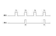
- an irradiation region to which a given light pattern is irradiated is set at time T2 based on the result of stereo matching processing based on the image taken at time T1. Then, at the time T3 including the time T2 as a part, the image of the irradiated place is taken. Similarly, an irradiation region to which a given light pattern is irradiated is set at time T5 based on the result of stereo matching processing based on the image taken at time T4. Then, at the time T6 including the time T5 as a part, the image of the irradiated place is taken.
- FIG. 7 is a diagram schematically showing an example of an image taken when a given light pattern is not irradiated.
- FIG. 8 is a diagram schematically showing an example of an image taken when the light pattern is irradiated.
- the region R is specified as the irradiation region.
- the region R on the table which has no feature points or few feature points, is set as the irradiation region.
- the region R is irradiated with a given light pattern, and the image shown in FIG. 8 is taken at time T3.
- the CPU 16 may monitor the time after the execution of the process shown in S104 to S107 is started. Then, when the monitored time exceeds a predetermined time, the CPU 16 may determine that the turn-off time is satisfied, and the driver 18 may execute the process shown in S109.
- the CPU 16 may monitor the number of times the processes shown in S104 to S107 are continuously executed without executing the processes shown in S101 to S103. Then, when the number of times monitored exceeds a predetermined number of times, the CPU 16 may determine that the turn-off time is satisfied, and the driver 18 may execute the process shown in S109.
- the CPU 16 may specify the difference between the image taken in the immediately preceding frame and the image taken in the frame. Then, when the difference is larger than the predetermined difference, the CPU 16 may determine that the extinguishing time is satisfied, and the driver 18 may execute the process shown in S109. Alternatively, when the specified difference is smaller than the predetermined difference for a predetermined time or more, the CPU 16 may determine that the extinguishing time is satisfied, and the driver 18 may execute the process shown in S109.
- the light pattern irradiation control device 1 may include a motion sensor. Then, when the value representing the magnitude of the movement, which is the measurement result of the motion sensor in the frame, is larger than the predetermined value, the CPU 16 determines that the extinguishing time is satisfied, and the driver 18 executes the process shown in S109. You may. Alternatively, when the value representing the magnitude of the above-mentioned movement is smaller than the predetermined value for a predetermined time or more, the CPU 16 may determine that the extinguishing time is satisfied, and the driver 18 may execute the process shown in S109.
- the frame in which the light emitting module 26 emits light and the frame in which the position and orientation of the light emitting module 26 are changed may arrive alternately. Further, the position and orientation of the light emitting module 26 may be changed between the time when the light emitting module 26 emits light and the time when the light emitting module emits light in the next frame.
- the CPU 16 may calculate the number of feature points extracted by the feature extraction engine 14 from the image for each of the plurality of regions in the image captured by the photographing unit 10.
- the region may be the same region as the unit region described above, or may be a different region.
- the CPU 16 may specify the irradiation region based on the calculated number of feature points. For example, a region in the captured image in which the calculated feature points are less than a predetermined number may be specified as an irradiation region. Alternatively, for example, the region having the fewest calculated feature points in the captured image may be specified as the irradiation region.
- the reason why the reliability indicated by the reliability data generated by the depth engine 12 is low may not be due to the absence of feature points or the lack of feature points. In such a case, it may be effective to specify the irradiation region based on the feature points extracted by the feature extraction engine 14.
- the irradiation region may be specified based on the reliability data and the calculated number of feature points. For example, in the process shown in S104, when a plurality of regions corresponding to reliability data indicating a reliability lower than a predetermined reliability are specified, the calculated feature points are the smallest among the plurality of regions. The region may be identified as an irradiation region.
- the CPU 16 or the feature extraction engine 14 may execute the object recognition process for the image captured by the photographing unit 10. Then, for example, the area where a predetermined object such as a floor, a wall, or a table is recognized may be specified as an irradiation area.
- the light pattern irradiation control device 1 may include an acceleration sensor. Then, the measurement result (for example, information in the direction of gravity) of the acceleration sensor may be used in the above-mentioned object recognition process.
- any irradiation region may be specified based on another criterion (for example, given importance). Then, a given light pattern may be applied to a place in the real space that appears in the specified irradiation area.
- a given light pattern may be sequentially irradiated to a place in the real space appearing in each irradiation region.
- the irradiation unit 20 even if the irradiation unit 20 irradiates the light pattern, if the reliability indicated by the reliability data does not become higher than the predetermined reliability, the irradiation unit 20 does not irradiate the light pattern. You may do so. For example, when it is continuously confirmed that the average reliability value is not equal to or higher than the predetermined value in the process shown in S103 over a predetermined number of frames, the light pattern irradiation control device 1 does not execute the process shown in S104 and S105. You may return to the process shown in S101. For example, when the cause of the low reliability is occlusion or noise, the reliability indicated by the reliability data may not be higher than the predetermined reliability even if the light pattern is irradiated.
- the light pattern irradiation control device 1 may include a motion sensor. When the amount of movement from the immediately preceding frame is smaller than the predetermined amount of movement, the irradiation unit 20 may not irradiate the light pattern.
- the irradiation region to be irradiated with the light pattern which occupies a part of the image, is specified based on the image taken by the photographing unit 10. Then, the irradiation unit 20 is controlled so as to irradiate a given light pattern to a place in the real space appearing in the irradiation region. Therefore, according to the present embodiment, the power consumption can be reduced as compared with the case where a given light pattern is irradiated over a wide range.
- the irradiation output is proportional to the square of the irradiation radius. Therefore, if the irradiation radius is halved, the irradiation output becomes 1/4.
- the present invention is not limited to the above-described embodiment.
- the photographing unit 10 and the irradiation unit 20 may be provided on different devices.
- a photographing unit that captures an image used for generating depth data (hereinafter referred to as a first photographing unit) and a photographing unit that captures an image used for specifying an irradiation area (hereinafter referred to as a second photographing unit). It may be a separate body from (called a part).
- irradiation control may be executed based on the image captured by the second imaging unit.
- the first photographing unit may photograph an object irradiated with a given light pattern by the irradiation control.
- depth data may be generated based on the image taken by the first photographing unit.
- the second photographing unit and the irradiation unit 20 may be provided in an integrated device, and the first photographing unit may be provided in a device different from the device.
- the feature extraction engine 14 may extract feature points from one image. Then, the irradiation region in the image may be specified based on the result of the extraction.
- the present invention can also be applied to the generation of depth data by a method other than the stereo matching method.
Landscapes
- Physics & Mathematics (AREA)
- Engineering & Computer Science (AREA)
- General Physics & Mathematics (AREA)
- Computer Vision & Pattern Recognition (AREA)
- Electromagnetism (AREA)
- Radar, Positioning & Navigation (AREA)
- Remote Sensing (AREA)
- Length Measuring Devices By Optical Means (AREA)
- Measurement Of Optical Distance (AREA)
Priority Applications (1)
| Application Number | Priority Date | Filing Date | Title |
|---|---|---|---|
| JP2021520697A JP7399160B2 (ja) | 2019-05-17 | 2020-05-07 | 光パターン照射制御装置及び光パターン照射制御方法 |
Applications Claiming Priority (2)
| Application Number | Priority Date | Filing Date | Title |
|---|---|---|---|
| JP2019-093819 | 2019-05-17 | ||
| JP2019093819 | 2019-05-17 |
Publications (1)
| Publication Number | Publication Date |
|---|---|
| WO2020235348A1 true WO2020235348A1 (ja) | 2020-11-26 |
Family
ID=73458515
Family Applications (1)
| Application Number | Title | Priority Date | Filing Date |
|---|---|---|---|
| PCT/JP2020/018591 Ceased WO2020235348A1 (ja) | 2019-05-17 | 2020-05-07 | 光パターン照射制御装置及び光パターン照射制御方法 |
Country Status (2)
| Country | Link |
|---|---|
| JP (1) | JP7399160B2 (https=) |
| WO (1) | WO2020235348A1 (https=) |
Cited By (3)
| Publication number | Priority date | Publication date | Assignee | Title |
|---|---|---|---|---|
| JP7388601B1 (ja) * | 2022-05-09 | 2023-11-29 | 三菱電機株式会社 | 構造物計測装置、データ処理装置、及び構造物計測方法 |
| JP2024513936A (ja) * | 2021-04-20 | 2024-03-27 | 上海図漾信息科技有限公司 | 深度データ測定ヘッド、計算装置及び測定方法 |
| US12467744B2 (en) | 2020-07-22 | 2025-11-11 | Shanghai Percipio Technology Limited | Depth data measuring device and structured light projection unit |
Citations (7)
| Publication number | Priority date | Publication date | Assignee | Title |
|---|---|---|---|---|
| JP2007017355A (ja) * | 2005-07-08 | 2007-01-25 | Omron Corp | ステレオ対応づけのための投光パターンの生成装置及び生成方法 |
| JP2008232776A (ja) * | 2007-03-20 | 2008-10-02 | Fujifilm Corp | 3次元形状計測装置および方法並びにプログラム |
| JP2010091492A (ja) * | 2008-10-10 | 2010-04-22 | Fujifilm Corp | 3次元形状計測用撮影装置および方法並びにプログラム |
| JP2011209019A (ja) * | 2010-03-29 | 2011-10-20 | Sony Corp | ロボット装置及びロボット装置の制御方法 |
| JP2012098087A (ja) * | 2010-10-29 | 2012-05-24 | Canon Inc | 測定装置及び測定方法 |
| JP2017530352A (ja) * | 2014-09-11 | 2017-10-12 | サイバーオプティクス コーポレーション | 三次元表面形状計測における多数のカメラ及び光源からの点群統合 |
| US20180330520A1 (en) * | 2017-05-11 | 2018-11-15 | Dantec Dynamics A/S | Method and system for calibrating a velocimetry system |
-
2020
- 2020-05-07 JP JP2021520697A patent/JP7399160B2/ja active Active
- 2020-05-07 WO PCT/JP2020/018591 patent/WO2020235348A1/ja not_active Ceased
Patent Citations (7)
| Publication number | Priority date | Publication date | Assignee | Title |
|---|---|---|---|---|
| JP2007017355A (ja) * | 2005-07-08 | 2007-01-25 | Omron Corp | ステレオ対応づけのための投光パターンの生成装置及び生成方法 |
| JP2008232776A (ja) * | 2007-03-20 | 2008-10-02 | Fujifilm Corp | 3次元形状計測装置および方法並びにプログラム |
| JP2010091492A (ja) * | 2008-10-10 | 2010-04-22 | Fujifilm Corp | 3次元形状計測用撮影装置および方法並びにプログラム |
| JP2011209019A (ja) * | 2010-03-29 | 2011-10-20 | Sony Corp | ロボット装置及びロボット装置の制御方法 |
| JP2012098087A (ja) * | 2010-10-29 | 2012-05-24 | Canon Inc | 測定装置及び測定方法 |
| JP2017530352A (ja) * | 2014-09-11 | 2017-10-12 | サイバーオプティクス コーポレーション | 三次元表面形状計測における多数のカメラ及び光源からの点群統合 |
| US20180330520A1 (en) * | 2017-05-11 | 2018-11-15 | Dantec Dynamics A/S | Method and system for calibrating a velocimetry system |
Cited By (4)
| Publication number | Priority date | Publication date | Assignee | Title |
|---|---|---|---|---|
| US12467744B2 (en) | 2020-07-22 | 2025-11-11 | Shanghai Percipio Technology Limited | Depth data measuring device and structured light projection unit |
| JP2024513936A (ja) * | 2021-04-20 | 2024-03-27 | 上海図漾信息科技有限公司 | 深度データ測定ヘッド、計算装置及び測定方法 |
| JP7664658B2 (ja) | 2021-04-20 | 2025-04-18 | 上海図漾信息科技有限公司 | 深度データ測定ヘッド、計算装置及び測定方法 |
| JP7388601B1 (ja) * | 2022-05-09 | 2023-11-29 | 三菱電機株式会社 | 構造物計測装置、データ処理装置、及び構造物計測方法 |
Also Published As
| Publication number | Publication date |
|---|---|
| JP7399160B2 (ja) | 2023-12-15 |
| JPWO2020235348A1 (https=) | 2020-11-26 |
Similar Documents
| Publication | Publication Date | Title |
|---|---|---|
| TWI817996B (zh) | 針對三維深度感測及二維成像調整攝影機曝光 | |
| JP7399160B2 (ja) | 光パターン照射制御装置及び光パターン照射制御方法 | |
| US20150116460A1 (en) | Method and apparatus for generating depth map of a scene | |
| US20140267427A1 (en) | Projector, method of controlling projector, and program thereof | |
| CN112752026A (zh) | 自动对焦方法、装置、电子设备和计算机可读存储介质 | |
| JP2011169701A (ja) | 物体検出装置および情報取得装置 | |
| CN110198409A (zh) | 终端的控制方法及控制装置、终端及计算机可读存储介质 | |
| CN109299662A (zh) | 深度数据计算设备与方法及人脸识别设备 | |
| WO2019184184A1 (zh) | 目标图像获取系统与方法 | |
| CN110308458A (zh) | 调节方法、调节装置、终端及计算机可读存储介质 | |
| CN110335303A (zh) | 图像处理方法和装置、及存储介质 | |
| JP2001298655A (ja) | 撮像装置および方法、並びに記録媒体 | |
| CN114885142B (zh) | 一种投影设备及调节投影亮度方法 | |
| CN114866751A (zh) | 一种投影设备及触发校正方法 | |
| US20230396746A1 (en) | Image projection system and image projection method | |
| JP4680558B2 (ja) | 撮影及び3次元形状復元方法、並びに撮影及び3次元形状復元システム | |
| EP3163369B1 (en) | Auto-focus control in a camera to prevent oscillation | |
| JP7013730B2 (ja) | 画像生成制御装置、画像生成制御方法、及び画像生成制御プログラム | |
| WO2019065458A1 (ja) | 映像生成装置、映像撮影装置、映像撮影システム、映像生成方法、制御プログラム及び記録媒体 | |
| JP6681141B2 (ja) | 口腔内を三次元測定する方法および装置 | |
| US11501408B2 (en) | Information processing apparatus, information processing method, and program | |
| CN110245618B (zh) | 3d识别装置及方法 | |
| JP2012169903A (ja) | カメラ | |
| CN113327280A (zh) | 结构光发射模组、图像获取方法和电子设备 | |
| CN119788826B (zh) | 一种投影设备及入幕方法 |
Legal Events
| Date | Code | Title | Description |
|---|---|---|---|
| 121 | Ep: the epo has been informed by wipo that ep was designated in this application |
Ref document number: 20809822 Country of ref document: EP Kind code of ref document: A1 |
|
| ENP | Entry into the national phase |
Ref document number: 2021520697 Country of ref document: JP Kind code of ref document: A |
|
| NENP | Non-entry into the national phase |
Ref country code: DE |
|
| 122 | Ep: pct application non-entry in european phase |
Ref document number: 20809822 Country of ref document: EP Kind code of ref document: A1 |