WO2020235192A1 - 静電容量検出センサ - Google Patents
静電容量検出センサ Download PDFInfo
- Publication number
- WO2020235192A1 WO2020235192A1 PCT/JP2020/011213 JP2020011213W WO2020235192A1 WO 2020235192 A1 WO2020235192 A1 WO 2020235192A1 JP 2020011213 W JP2020011213 W JP 2020011213W WO 2020235192 A1 WO2020235192 A1 WO 2020235192A1
- Authority
- WO
- WIPO (PCT)
- Prior art keywords
- electrode
- sense
- drive
- drive signal
- value
- Prior art date
- Legal status (The legal status is an assumption and is not a legal conclusion. Google has not performed a legal analysis and makes no representation as to the accuracy of the status listed.)
- Ceased
Links
Images








Classifications
-
- G—PHYSICS
- G06—COMPUTING OR CALCULATING; COUNTING
- G06F—ELECTRIC DIGITAL DATA PROCESSING
- G06F3/00—Input arrangements for transferring data to be processed into a form capable of being handled by the computer; Output arrangements for transferring data from processing unit to output unit, e.g. interface arrangements
- G06F3/01—Input arrangements or combined input and output arrangements for interaction between user and computer
- G06F3/03—Arrangements for converting the position or the displacement of a member into a coded form
- G06F3/041—Digitisers, e.g. for touch screens or touch pads, characterised by the transducing means
- G06F3/044—Digitisers, e.g. for touch screens or touch pads, characterised by the transducing means by capacitive means
-
- H—ELECTRICITY
- H03—ELECTRONIC CIRCUITRY
- H03K—PULSE TECHNIQUE
- H03K17/00—Electronic switching or gating, i.e. not by contact-making and –breaking
- H03K17/94—Electronic switching or gating, i.e. not by contact-making and –breaking characterised by the way in which the control signals are generated
- H03K17/96—Touch switches
- H03K17/962—Capacitive touch switches
-
- G—PHYSICS
- G01—MEASURING; TESTING
- G01B—MEASURING LENGTH, THICKNESS OR SIMILAR LINEAR DIMENSIONS; MEASURING ANGLES; MEASURING AREAS; MEASURING IRREGULARITIES OF SURFACES OR CONTOURS
- G01B7/00—Measuring arrangements characterised by the use of electric or magnetic techniques
-
- G—PHYSICS
- G01—MEASURING; TESTING
- G01D—MEASURING NOT SPECIALLY ADAPTED FOR A SPECIFIC VARIABLE; ARRANGEMENTS FOR MEASURING TWO OR MORE VARIABLES NOT COVERED IN A SINGLE OTHER SUBCLASS; TARIFF METERING APPARATUS; MEASURING OR TESTING NOT OTHERWISE PROVIDED FOR
- G01D5/00—Mechanical means for transferring the output of a sensing member; Means for converting the output of a sensing member to another variable where the form or nature of the sensing member does not constrain the means for converting; Transducers not specially adapted for a specific variable
- G01D5/12—Mechanical means for transferring the output of a sensing member; Means for converting the output of a sensing member to another variable where the form or nature of the sensing member does not constrain the means for converting; Transducers not specially adapted for a specific variable using electric or magnetic means
- G01D5/14—Mechanical means for transferring the output of a sensing member; Means for converting the output of a sensing member to another variable where the form or nature of the sensing member does not constrain the means for converting; Transducers not specially adapted for a specific variable using electric or magnetic means influencing the magnitude of a current or voltage
- G01D5/24—Mechanical means for transferring the output of a sensing member; Means for converting the output of a sensing member to another variable where the form or nature of the sensing member does not constrain the means for converting; Transducers not specially adapted for a specific variable using electric or magnetic means influencing the magnitude of a current or voltage by varying capacitance
- G01D5/2405—Mechanical means for transferring the output of a sensing member; Means for converting the output of a sensing member to another variable where the form or nature of the sensing member does not constrain the means for converting; Transducers not specially adapted for a specific variable using electric or magnetic means influencing the magnitude of a current or voltage by varying capacitance by varying dielectric
-
- G—PHYSICS
- G06—COMPUTING OR CALCULATING; COUNTING
- G06F—ELECTRIC DIGITAL DATA PROCESSING
- G06F3/00—Input arrangements for transferring data to be processed into a form capable of being handled by the computer; Output arrangements for transferring data from processing unit to output unit, e.g. interface arrangements
- G06F3/01—Input arrangements or combined input and output arrangements for interaction between user and computer
- G06F3/03—Arrangements for converting the position or the displacement of a member into a coded form
- G06F3/041—Digitisers, e.g. for touch screens or touch pads, characterised by the transducing means
- G06F3/0416—Control or interface arrangements specially adapted for digitisers
-
- B—PERFORMING OPERATIONS; TRANSPORTING
- B62—LAND VEHICLES FOR TRAVELLING OTHERWISE THAN ON RAILS
- B62D—MOTOR VEHICLES; TRAILERS
- B62D1/00—Steering controls, i.e. means for initiating a change of direction of the vehicle
- B62D1/02—Steering controls, i.e. means for initiating a change of direction of the vehicle vehicle-mounted
- B62D1/04—Hand wheels
- B62D1/06—Rims, e.g. with heating means; Rim covers
-
- G—PHYSICS
- G06—COMPUTING OR CALCULATING; COUNTING
- G06F—ELECTRIC DIGITAL DATA PROCESSING
- G06F2203/00—Indexing scheme relating to G06F3/00 - G06F3/048
- G06F2203/041—Indexing scheme relating to G06F3/041 - G06F3/045
- G06F2203/04107—Shielding in digitiser, i.e. guard or shielding arrangements, mostly for capacitive touchscreens, e.g. driven shields, driven grounds
-
- G—PHYSICS
- G06—COMPUTING OR CALCULATING; COUNTING
- G06F—ELECTRIC DIGITAL DATA PROCESSING
- G06F2203/00—Indexing scheme relating to G06F3/00 - G06F3/048
- G06F2203/041—Indexing scheme relating to G06F3/041 - G06F3/045
- G06F2203/04108—Touchless 2D- digitiser, i.e. digitiser detecting the X/Y position of the input means, finger or stylus, also when it does not touch, but is proximate to the digitiser's interaction surface without distance measurement in the Z direction
-
- H—ELECTRICITY
- H03—ELECTRONIC CIRCUITRY
- H03K—PULSE TECHNIQUE
- H03K2217/00—Indexing scheme related to electronic switching or gating, i.e. not by contact-making or -breaking covered by H03K17/00
- H03K2217/94—Indexing scheme related to electronic switching or gating, i.e. not by contact-making or -breaking covered by H03K17/00 characterised by the way in which the control signal is generated
- H03K2217/96—Touch switches
- H03K2217/9607—Capacitive touch switches
- H03K2217/96071—Capacitive touch switches characterised by the detection principle
Definitions
- the present invention relates to a capacitance detection sensor.
- the HoD sensor detects, for example, the holding state of the steering wheel.
- the capacitance detection sensor for example, a certain value is used as a reference value, and the detected capacitance or the like is used as a reference. If it exceeds the value, it can be determined that the steering wheel or the like is touched (held), and if it is less than the reference value, it can be determined that the steering wheel is not touched (held).
- the hand of the person to be detected holds the steering wheel or the like but does not hold it, or determines that the hand does not hold the steering wheel or the like.
- Such erroneous detection may occur, and it is difficult to accurately determine whether or not the steering wheel or the like is held.
- one of the first electrode, the second electrode, and the first electrode or the second electrode is a sense electrode, and the sense applied to the sense electrode is used.
- the sense signal is applied to the sense electrode by the sense signal generation unit that generates a signal and the sense signal generation unit, the amount of charge transfer corresponding to the capacitance in the sense electrode is detected as a detection value.
- the first electrode or the other of the second electrodes is used as a drive electrode, and a first drive signal is applied to the drive electrode.
- the first detected value detected by the detection unit and the second drive signal having the same frequency as the first drive signal but different in phase are applied to the drive electrode.
- a determination unit that determines whether or not the detection target is close to both the first electrode and the second electrode based on the difference from the second detection value detected by the detection unit. It is characterized by having.
- the self-capacitance type capacitance detection sensor shown in FIG. 1 has a sensor unit 10 having a sense electrode 11 and a circuit unit 20.
- the circuit unit 20 includes a sense signal generation unit 30, a detection unit 40, a contact determination unit 50, a control unit 70, and the like, and the contact determination unit 50 has a memory 51 and a determination unit 52.
- a leak capacitance CL1 is generated between the sense electrode 11 and the GND, and a capacitance C is generated between a part 81 of the human body 80 to be detected and the sense electrode 11. F1 is occurring.
- a coupling capacitance CFG is generated between the human body 80 and GND.
- a part 81 of the human body 80 is, for example, a finger or a palm.
- an AC voltage is applied to the sense electrode 11 from the sense signal generation unit 30, and when a part 81 of the human body 80 approaches the sense electrode 11, the value of the capacitance C F1 .
- the amount of electric charge that moves that is, the amount of electric charge that moves increases.
- the value of the amount of movement of the electric charge is detected by the detection unit 40, and the value is stored in the memory 51.
- the determination unit 52 determines whether or not the value of the amount of movement of the electric charge detected by the detection unit 40 stored in the memory 51 exceeds a predetermined threshold value, and a part 81 of the human body 80 is the sensor unit 10. Determine if you are touching.
- the determination unit 52 determines that a part 81 of the human body 80 is touching the sensor unit 10 and sets the predetermined threshold value. If it does not exceed, it is determined that the sensor unit 10 is not touched by a part 81 of the human body 80, and contact or non-contact information is output.
- the control unit 70 controls the series of capacitance detection operations described above.
- the portion that senses the contact of the sensor unit 10 is composed of an insulator that covers the sense electrode 11. That is, when a part 81 of the human body 80 touches the sensor unit 10, the part 81 of the human body 80 comes close to the sense electrode 11 separated by the insulator.
- the sense electrode and the drive electrode are provided at positions separated by the insulator, and it is assumed that a part of the human body does not directly touch these electrodes.
- erroneous detection may occur because the capacitance fluctuates due to changes in the environment, for example, changes in temperature or external factors. is there. Specifically, even if a part 81 of the human body 80 is not touching the sensor unit 10, the detection unit 40 detects a large capacitance, and the sensor unit 10 is touched by the part 81 of the human body 80. When the determination is made by the determination unit 52, or even if a part 81 of the human body 80 touches the sensor unit 10, the detection unit 40 detects that the capacitance is small, and the sensor unit 10 is touched by the part 81 of the human body 80. It may be determined by the determination unit 52 that it is not.
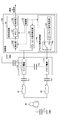
- the capacitance detection sensor in the present embodiment is a self-capacitance type capacitance detection sensor, and has a sensor unit 110 having a sense electrode 111 and a drive electrode 112, and a circuit unit 120.
- the capacitance detection sensor in the present embodiment is for determining whether or not a predetermined portion of the sensor unit 110 is held by a human hand or the like.
- the circuit unit 120 includes a sense signal generation unit 130, a detection unit 140, a holding determination unit 150, a drive signal control unit 160, a control unit 170, and the like, and the holding determination unit 150 includes a memory 151 and a determination unit 152.
- the drive signal control unit 160 includes a drive signal generation unit 161 and a switch 162 that serves as a selection unit for selecting a signal applied to the drive electrode 112.
- the sense electrode 111 and the drive electrode 112 may be referred to as a first electrode and a second electrode. In this case, either one of the first electrode and the second electrode is used. Is the sense electrode 111, and the other is the drive electrode 112.
- the capacitance detection sensor according to this embodiment has a first electrode and a second electrode. Further, a plurality of sense electrodes 111 may be provided and one of them may be selected, or a plurality of drive electrodes 112 may be provided and one of them may be selected. Good. It should be noted that three or more electrodes including the first electrode and the second electrode are provided, and the sense electrode and the drive electrode may be selected from the three or more electrodes.
- a leak capacitance CL1 is generated between the sense electrode 111 and GND, and a part 81 of the human body 80 to be detected and the sense electrode 111 are separated from each other.
- the capacitance C F1 is generated and a part 81 of the human body 80 approaches the sense electrode 111, the value of the capacitance C F 1 becomes large.
- a capacitance CF2 is generated between the other part 82 of the human body 80 and the drive electrode 112, and when the other part 82 of the human body 80 approaches the drive electrode 112, it is electrostatically charged. The value of the capacitance C F2 becomes large.
- the sense electrode 111 and the drive since it is detected that a part 81 of the same human body 80 and another part 82 are simultaneously close to the sense electrode 111 and the drive electrode 112, respectively, the sense electrode 111 and the drive
- the distance between the electrode 112 and the electrode 112 is preferably 1 m or less.
- a capacitance C SD is generated between the sense electrode 111 and the drive electrode 112
- the electric charge of the drive electrode 112 is the other part 82 of the human body, the human body 80, and the human body. Since it is premised that the sense electrode 111 is affected through a part of 81, it is preferable that the value of the capacitance CSD is as small as possible. In the description here, it is assumed that the capacitance C SD is small and can be ignored.
- the sense signal generation unit 130 generates a sense signal to be applied to the sense electrode 111, and applies the sense signal to the sense electrode 111 as an AC voltage.
- the sense signal is applied to the sense electrode 111 by the sense signal generation unit 130, the detection unit 140 detects the amount of charge transfer corresponding to the capacitance in the sense electrode 111 as a detection value, and causes the memory 151.
- the determination unit 152 determines whether to hold or not based on the detected value stored in the memory 151, and outputs the determination.
- the determination unit 152 has the first detection value detected by the detection unit 140 and the first drive signal to the drive electrode 112 in a state where the first drive signal is applied to the drive electrode 112.
- the first electrode and the second electrode are based on the difference from the second detection value detected by the detection unit 140 in a state where the second drive signal having the same frequency and a different phase is applied. It is determined whether or not the detection target is close to both of the above.
- the specific method will be described later, but here, the first drive signal is the same signal as the sense signal. Further, the second drive signal is the same signal as the drive signal generated in the drive signal generation unit 161.
- the control unit 170 controls the above-mentioned series of capacitance detection operations.
- the drive signal control unit 160 selects a sense signal or a drive signal and applies it to the drive electrode 112. Specifically, the drive signal generation unit 161 provided in the drive signal control unit 160 generates a drive signal.
- the switch 162 provided in the drive signal control unit 160 is connected to the drive electrode 112 and also to the sense signal generation unit 130 and the drive signal generation unit 161.
- the connection destination to the drive electrode 112 is the sense signal generation unit 130.
- the signal applied to the drive electrode 112 is selected by switching between and the drive signal generation unit 161. That is, the switch 162 provided in the drive signal control unit 160 selects the sense signal generated in the sense signal generation unit 130 or the drive signal generated in the drive signal generation unit 161 and outputs the drive signal to the drive electrode 112.
- the sense signal generation unit 130 is connected to the drive signal control unit 160.
- the AC sense signal output from the sense signal generation unit 130 and the AC drive signal output from the drive signal generation unit 161 have the same frequency but a phase of 180 °. It is out of alignment.
- the sense signal and the drive signal may be at least out of phase, but it is preferable that the sense signal and the drive signal are out of phase by 180 ° because the detection accuracy is high.
- the circuit unit 120 also applies the sense signal to the drive electrode 112 in a state where the sense signal generated by the sense signal generation unit 130 is applied to the sense electrode 111.
- the sense signal generation unit 130 generates a sense signal and applies it to the sense electrode 111.
- the switch 162 of the drive signal control unit 160 selects the sense signal by connecting the sense signal generation unit 130 and the drive electrode 112, and applies the sense signal to the drive electrode 112.
- the control unit 170 controls the timing of these operations, the detection timing by the detection unit 140, and the holding determination timing by the holding determination unit 150.
- step 104 with the sense signal applied to the sense electrode 111 and the drive electrode 112, the detection unit 140 detects the amount of charge transfer corresponding to the capacitance in the sense electrode 111. It is detected as d1 and stored in the memory 151.
- This detected value V d1 is a value as shown in the following equation 1.
- step 106 in a state where the sense signal generated by the sense signal generation unit 130 is applied to the sense electrode 111, the drive signal control unit 160 transmits the drive signal generated by the drive signal generation unit 161 to the drive electrode. Apply to 112. Specifically, in a state where the sense signal generated in the sense signal generation unit 130 is applied to the sense electrode 111, the switch 162 in the drive signal control unit 160 connects the drive signal generation unit 161 and the drive electrode 112. The drive signal is selected by, and the drive signal is applied to the drive electrode 112.
- step 108 in a state where the sense signal is applied to the sense electrode 111 and the drive signal is applied to the drive electrode 112, the detection unit 140 moves the charge corresponding to the capacitance in the sense electrode 111.
- the amount is detected as a detection value V d2 and stored in the memory 151.
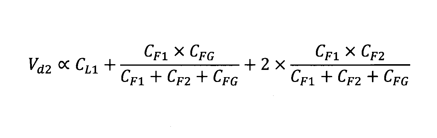
- This detected value V d2 is a value as shown in the following equation 2.
- the sense signal and the drive signal since the phase is a signal of opposite phase that shifted from each other by 180 °, the body 80 is rocked in the opposite phase to the micro through C F2, the detection value V d2 is detected as shown in Equation 1 The value is different from the value V d1 .
- step 110 the determination unit 152 calculates the difference V d2- V d1 from the detection value V d1 and the detection value V d2 stored in the memory 151.
- the calculated difference V d2- V d1 has a value as shown in the following equation 3.
- the difference V d2 -V d1 to be calculated is a value proportional to the product of the capacitance C F1 and the capacitance C F2, the electrostatic capacitance C F1 and the capacitance C F2 The value increases only when both of them are sufficiently large.
- the value of the difference V d2- V d1 is extremely small. Therefore, only when a part 81 of the human body 80 is close to both the sense electrode 111 and the drive electrode 112, that is, the portion of the sensor unit 110 where the sense electrode 111 and the drive electrode 112 are provided is the human body 80.
- the value of the difference V d2- V d1 becomes large only when a part 81 holds it.
- the self-capacitance type capacitance detection sensor in the prior art usually does not have a drive electrode.
- the capacitance detection sensor of the present invention includes a drive electrode 112 which is a self-capacitance method but does not originally exist, and two types of signals having the same frequency but different phases are sequentially applied to the drive electrode 112, respectively.
- step 112 the determination unit 152 determines whether or not the value of the difference V d2- V d1 is larger than the predetermined first threshold value Th.
- the determination unit 152 determines the first electrode (sense electrode 111) and the second electrode (drive electrode 112). It is determined that the detection target is close to both of the above. That is, it is determined that the process proceeds to step 114 (S114) and the holding is performed, and the determination unit 152 outputs the information that the holding is performed and ends.
- step 116 S116
- the determination unit 152 holds the difference. Outputs information about what has not been done and exits.
- the difference V d2- V d1 shown in Equation 3 has an extremely small value when it is close only to the sense electrode 111 or when it is close only to the drive electrode 112, and the sense electrode. Only when the detection target is close to both the 111 and the drive electrode 112, that is, when the part 81 of the human body 80 holds the portion of the sensor unit 110 where the sense electrode 111 and the drive electrode 112 are provided. The value increases. Therefore, the determination unit 152 can accurately determine whether or not the portion of the sensor unit 110 where the sense electrode 111 and the drive electrode 112 are provided is held.
- the difference V d2 -V d1 shown in Equation 3 since the component of the leakage capacitance C L1 to change numeric such as by temperature change does not exist, there is no dependency on the environmental changes such as temperature. Therefore, it is not necessary to change the predetermined first threshold value Vth depending on the environment such as temperature, and the predetermined first threshold value Vth can be fixed. Therefore, even when the power of the capacitance detection sensor is turned on while holding the predetermined portion of the sensor unit 110, the obtained difference V d2- V d1 is the predetermined first value. If the threshold value Th is exceeded, it can be determined that the determination unit 152 holds the portion of the sensor unit 110 where the sense electrode 111 and the drive electrode 112 are provided.
- the determination unit 152 is the sensor unit. It is not determined that the portion where the sense electrode 111 and the drive electrode 112 of 110 are provided is held. Specifically, when a part 81 of the human body 80 is close to the sense electrode 111 and a part 181 of the human body 180 different from the human body 80 is close to the drive electrode 112, the human body 80 is affected by the change in the drive signal. I will not receive it.
- the detected value V d1 when the sense signal is applied to the drive electrode 112 and the detected value V d2 when the drive signal is applied to the drive electrode 112 are the same value, so that the difference V d2- The value of V d1 is extremely small. Therefore, the determination unit 152 does not determine that the portion of the sensor unit 110 where the sense electrode 111 and the drive electrode 112 are provided is held.
- the denominator of the detection value V d1 and the detection value V d2 is detected, includes a coupling capacitance C FG between the human body and the GND, capacitance value of the coupling capacitance C FG is generated by the holding When it is overwhelmingly larger than C F1 and C F2 , the value of the difference V d2- V d1 may not be large.
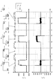
- a part 81 of the human body 80 is close to the sense electrode 111, and another part 82 of the same human body 80 is close to the drive electrode 112, as between the times T5 and T6. It was confirmed that the value of the difference V d2- V d1 greatly increased in the present state. At times T1, T2, T6, T8, and T9, the value of the difference V d2- V d1 increases momentarily, but the difference is momentarily set by appropriately setting the length of time for detection. The component in which the value of V d2- V d1 becomes large can be removed.
- this modification is preferably applied in cases such as when the value of the capacitance C SD between the sense electrodes 111 and drive electrode 112 can not be ignored.
- a modification 2 of the capacitance detection sensor according to the present embodiment will be described with reference to FIG.
- a first drive signal generation unit 163 and a second drive signal generation unit 164 are provided in the drive signal control unit 160. , Both are connected to the switch 162.
- the first drive signal generation unit 163 generates the first drive signal.
- the second drive signal generation unit 164 generates the second drive signal.
- the switch 162 can select a first drive signal or a second drive signal and apply it to the drive electrode 112.
- the first drive signal generated by the first drive signal generation unit 163 and the second drive signal generated by the second drive signal generation unit 164 are 180 ° out of phase and out of phase.
- the first drive signal and the second drive signal may be at least out of phase, but it is preferable that the first drive signal and the second drive signal are out of phase by 180 ° because the detection accuracy is high.
- the sense signal generation unit 130 is not connected to the drive signal control unit 160.
- the sense signal generated by the sense signal generation unit 130 and either the first drive signal or the second drive signal may be the same signal.
- the first drive signal generation unit 163 can be omitted rather than the configuration in which the sense signal generation unit 130 and the drive signal control unit 160 are connected.
- the second drive signal generation unit 164 corresponds to the drive signal generation unit 161.
- the sensor unit 210 has a first electrode 211 and a second electrode 212.
- one of the first electrode 211 and the second electrode 212 serves as a sense electrode and the other serves as a drive electrode.
- the circuit unit 220 includes a sense signal generation unit 130, a detection unit 140, a holding determination unit 150, a drive signal control unit 160, a control unit 170, a drive sense selection unit 230, and the like. Further, the holding determination unit 150 has a memory 151 and a determination unit 152.
- the drive sense selection unit 230 uses one of the first electrode 211 or the second electrode as a sense electrode and the other as a drive electrode. That is, the drive sense selection unit 230 selects a case where the sense signal generation unit 130 and the drive signal control unit 160 and the first electrode 211 and the second electrode 212 are connected in parallel or in a cross. be able to.
- the first electrode 211 and the sense signal generation unit 130 are connected, and the second electrode 212 and the drive signal control unit 160 are connected. And are connected.
- the first electrode 211 serves as a sense electrode
- the second electrode 212 serves as a drive electrode.
- the drive sense selection unit 230 when the drive sense selection unit 230 is connected to the cross, as shown in FIG. 11, the first electrode 211 and the drive signal control unit 160 are connected, and the second electrode 212 and the sense signal are generated.
- the unit 130 is connected.
- the first electrode 211 serves as the drive electrode
- the second electrode 212 serves as the sense electrode.
- the capacitance detection sensor of the present embodiment is a determination unit by switching between the sense electrode and the drive electrode by the drive sense selection unit 230 in the first electrode 211 and the second electrode 212. It is possible to improve the accuracy of determining whether or not to hold the 152.
- the determination unit 152 has the first detection value detected by the detection unit 140 and the first detection value on the drive electrode in a state where the first drive signal is applied to the drive electrode.
- the first electrode and the first electrode are based on the difference from the second detected value detected by the detection unit 140 in a state where the second drive signal having the same frequency and a different phase is applied. It is determined whether or not the detection target is close to both of the two electrodes.
- the first drive signal is the same signal as the sense signal generated by the sense signal generation unit 130.
- the second drive signal is the same signal as the drive signal generated in the drive signal generation unit 161.
- the determination unit 152 uses the difference value obtained when the first electrode 211 is the sense electrode and the second electrode 212 as the drive electrode, and the second electrode 212 as the sense electrode, and is the first electrode.
- the difference from the difference value obtained when 211 is used as the drive electrode is equal to or less than a predetermined second threshold value, the detection target is close to both the first electrode 211 and the second electrode 212. Make a judgment that you are doing.
- the sense signal and the drive signal are signals having opposite phases that are 180 ° out of phase.
- step 202 the drive sense selection unit 230 is connected in parallel, that is, the first electrode 211 and the sense signal generation unit 130 are connected, and the second electrode is connected.
- the 212 and the drive signal control unit 160 are connected.
- the first electrode 211 becomes a sense electrode
- the second electrode 212 becomes a drive electrode.
- step 204 the drive signal control unit 160 becomes the drive electrode in the state where the sense signal generated by the sense signal generation unit 130 is applied to the first electrode 211 which becomes the sense electrode.
- a sense signal is also applied to the electrode 212.
- the switch 162 in the drive signal control unit 160 includes the sense signal generation unit 130 and the second electrode 212. Is connected to apply a sense signal to the second electrode 212.
- step 206 in a state where the sense signal is applied to the first electrode 211 and the second electrode 212, the detection unit 140 applies the capacitance of the first electrode 211 which is the sense electrode.
- the corresponding charge transfer amount is detected as the detection value Vs1d1 and stored in the memory 151.
- step 208 the drive signal control unit 160 becomes the drive electrode in the state where the sense signal generated by the sense signal generation unit 130 is applied to the first electrode 211 which becomes the sense electrode.
- the drive signal generated by the drive signal generation unit 161 is applied to the electrode 212.
- the switch 162 in the drive signal control unit 160 includes the drive signal generation unit 161 and the second electrode 212. Is connected to apply a drive signal to the second electrode 212.
- step 210 in a state where the sense signal is applied to the first electrode 211 and the drive signal is applied to the second electrode 212, the detection unit 140 is the first electrode which is the sense electrode.
- the amount of movement of the electric charge corresponding to the capacitance in 211 is detected as the detection value Vs1d2 and stored in the memory 151.
- step 214 the drive sense selection unit 230 is connected to the cross as shown in FIG. 11, that is, the first electrode 211 and the drive signal control unit 160 are connected, and the second electrode is connected.
- the 212 and the sense signal generator 130 are connected.
- the first electrode 211 becomes a drive electrode
- the second electrode 212 becomes a sense electrode.
- step 216 the drive signal control unit 160 becomes the first drive electrode in a state where the sense signal generated by the sense signal generation unit 130 is applied to the second electrode 212 which becomes the sense electrode.
- a sense signal is also applied to the electrode 211 of.
- the switch 162 in the drive signal control unit 160 has the sense signal generation unit 130 and the first electrode 211. By connecting to, a sense signal is applied to the first electrode 211.
- step 218 in a state where the sense signal is applied to the first electrode 211 and the second electrode 212, the detection unit 140 applies the capacitance of the second electrode 212, which is the sense electrode.
- the corresponding charge transfer amount is detected as the detection value Vs2d1 and stored in the memory 151.
- step 220 the drive signal control unit 160 becomes the first drive electrode in a state where the sense signal generated by the sense signal generation unit 130 is applied to the second electrode 212 which becomes the sense electrode.
- the drive signal generated in the drive signal generation unit 161 is applied to the electrode 211 of the above.
- the switch 162 in the drive signal control unit 160 has the drive signal generation unit 161 and the first electrode 211. And apply a drive signal to the first electrode 211.
- step 222 in a state where the sense signal is applied to the second electrode 212 and the drive signal is applied to the first electrode 211, the detection unit 140 is the second electrode which is the sense electrode.
- the amount of movement of the electric charge corresponding to the capacitance in 212 is detected as the detected value Vs2d2 and stored in the memory 151.
- step 226 the determination unit 152 determines whether or not the value of the difference D1 is larger than the predetermined first threshold value Th1. If the value of the difference D1 is larger than the predetermined first threshold value Th1, the process proceeds to step 228, and if the value of the difference D1 is equal to or less than the predetermined first threshold value Th1, the process proceeds to step 232. Transition.
- step 228 the determination unit 152 determines whether or not the value of the difference D2 is larger than the predetermined first threshold value Th1. If the value of the difference D2 is larger than the predetermined first threshold value Th1, the process proceeds to step 230, and if the value of the difference D2 is equal to or less than the predetermined first threshold value Th1, the process proceeds to step 232. Transition.
- step 230 the determination unit 152 determines whether or not the value of D2-D1 is equal to or less than a predetermined second threshold value Th2. If the value of D2-D1 is equal to or less than the predetermined second threshold value Th2, the process proceeds to step 234, and if the value of D2-D1 is larger than the predetermined second threshold value Th2, the process proceeds to step 234. The process proceeds to step 232.
- step 232 the determination unit 152 determines that the portion of the sensor unit 210 where the first electrode 211 and the second electrode 212 are provided is not held, and information that the determination unit 152 does not hold the portion. Is output and exits.
- step 234 the determination unit 152 determines that the detection target is close to both the first electrode 211 and the second electrode 212. That is, the determination unit 152 determines that the portion of the sensor unit 210 where the first electrode 211 and the second electrode 212 are provided is held, outputs information that the second electrode 212 is provided, and ends. To do.
- the capacitance detection sensor of the present embodiment erroneous detection due to the influence of noise or the like can be suppressed by replacing the sense electrode and the drive electrode in the first electrode 211 and the second electrode 212.
- the value of the difference D1 and the value of the difference D2 are values proportional to the value on the right side of Equation 3, and in principle, they are the same even if the sense electrode and the drive electrode are exchanged. There is a possibility that the value of the difference D1 or the value of the difference D2 becomes a large value momentarily due to the influence of noise or the like, but both the value of the difference D1 and the value of the difference D2 become large values, and the values are omitted. The probability of being the same is extremely low.
- the determination unit 152 determines that the portion of the sensor unit 210 where the first electrode 211 and the second electrode 212 are provided is not held without being confused by the influence of noise or the like, the detection accuracy can be improved. Can be improved.
- the present embodiment is a steering handle, a door handle, a smartphone, or the like using the capacitance detection sensor in the first or second embodiment.
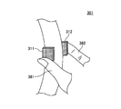
- the steering handle 301 according to the present embodiment has a first electrode 311 attached to the front side and a second electrode 312 attached to the back side, for example, the steering handle.
- the 301 is gripped, it is detected that the thumb 381 of the human body is close to the first electrode 311 and the index finger 382 is close to the second electrode 312. As a result, it is possible to accurately determine that the steering wheel 301 is being held.
- one of the first electrode 311 and the second electrode 312 corresponds to the sense electrode 111, and the other corresponds to the drive electrode 112. .
- the first electrode 311 corresponds to the first electrode 211
- the second electrode 312 corresponds to the second electrode 212.
- the first electrode 311 is attached to the front side and the second electrode 312 is attached to the back side, for example.
- the thumb 381 of the human body is close to the first electrode 311 and the fingers other than the thumb 381 such as the index finger 382 and the middle finger 383 are close to the second electrode 312. is there.
- the thumb 381 of the human body is close to the first electrode 311 and the fingers other than the thumb 381 such as the index finger 382 and the middle finger 383 are close to the second electrode 312. is there.
- the thumb 381 of the human body is close to the first electrode 311 and the fingers other than the thumb 381 such as the index finger 382 and the middle finger 383 are close to the second electrode 312.
- the electrodes 321, 322, 323, 324 are attached near the left side surface, and the electrodes 325, 326, 327, 328 are attached near the right side surface.
- a sense electrode and a drive electrode were selected from 321, 322, 323, 324, 325, 326, 327, and 328, and the two selected electrodes had the human thumb 381, the index finger 382, and the middle finger 383. It detects that either the ring finger 384 or the little finger 385 is close to each other. As a result, it is possible to accurately determine that the smartphone 303 is held.
Landscapes
- Engineering & Computer Science (AREA)
- Physics & Mathematics (AREA)
- General Physics & Mathematics (AREA)
- General Engineering & Computer Science (AREA)
- Theoretical Computer Science (AREA)
- Human Computer Interaction (AREA)
- Measurement Of Length, Angles, Or The Like Using Electric Or Magnetic Means (AREA)
- Geophysics And Detection Of Objects (AREA)
- Steering Controls (AREA)
- Switches That Are Operated By Magnetic Or Electric Fields (AREA)
Abstract
Description
最初に、図1に基づき、自己容量方式の静電容量検出センサを用いて検出を行う場合について説明する。図1に示される自己容量方式の静電容量検出センサは、センス電極11を有するセンサ部10と回路部20とを有している。回路部20は、センス信号発生部30、検出部40、接触判定部50、制御部70等を有しており、接触判定部50は、メモリ51と判定部52とを有している。
次に、第1の実施の形態における静電容量検出センサについて、図2に基づき説明する。本実施の形態における静電容量検出センサは、自己容量方式の静電容量検出センサであり、センス電極111及びドライブ電極112を有するセンサ部110と、回路部120とを有している。本実施の形態における静電容量検出センサは、センサ部110の所定の部分が、人の手等により保持されているか否かを判定するためのものである。回路部120は、センス信号発生部130、検出部140、保持判定部150、ドライブ信号制御部160、制御部170等を有しており、保持判定部150は、メモリ151と判定部152とを有している。ドライブ信号制御部160は、ドライブ信号発生部161と、ドライブ電極112に印加される信号を選択する選択部となるスイッチ162を有している。
次に、本実施の形態における静電容量検出センサを用いて、センサ部110が人の手等により保持されているか否かを判定するための検出方法について、図3に基づき説明する。


次に、本実施の形態における静電容量検出センサについて、図5に示されるような基板190の表面にセンス電極111とドライブ電極112とを設けた試験装置を用いて行った実験について説明する。ただし、この試験装置においても、センス電極111とドライブ電極112とは絶縁体により覆われており、人体80の一部81が直に電極に接触することはないものとする。
次に、本実施の形態における静電容量検出センサの変形例1について、図7に基づき説明する。図7に示されるように、本変形例における静電容量検出センサは、センス電極111とドライブ電極112との間にシールド電極113が設けられている。このシールド電極113には、センス信号発生部130によりセンス信号(即ち、第1のドライブ信号)が印加されている。これにより、センス電極111とドライブ電極112との間の静電容量CSDを小さくすることができる。
次に、本実施の形態における静電容量検出センサの変形例2について、図8に基づき説明する。図8に示されるように、本変形例における静電容量検出センサは、ドライブ信号制御部160内に、第1のドライブ信号発生部163と第2のドライブ信号発生部164とが設けられており、いずれもスイッチ162に接続されている。第1のドライブ信号発生部163は、第1のドライブ信号を発生させる。第2のドライブ信号発生部164は、第2のドライブ信号を発生させる。スイッチ162は、第1のドライブ信号または第2のドライブ信号を選択し、ドライブ電極112に印加することができる。第1のドライブ信号発生部163において発生した第1のドライブ信号と、第2のドライブ信号発生部164において発生した第2のドライブ信号とは位相が180°ずれており逆相となっている。第1のドライブ信号と第2のドライブ信号は、少なくとも位相がずれていればよいが、位相が180°ずれていると、検出精度が高くなるため好ましい。
次に、第2の実施の形態における静電容量検出センサは、図9に示されるように、センサ部210は、第1の電極211と第2の電極212とを有している。本実施の形態においては、第1の電極211及び第2の電極212は、いずれか一方がセンス電極となり、他方がドライブ電極となる。
次に、本実施の形態における静電容量検出センサを用いて、センサ部210が人の手等により保持されているか否かを判定するための検出方法について、図12に基づき説明する。尚、センス信号とドライブ信号とは、位相が180°ずれている逆相の信号である。
次に、第3の実施の形態について説明する。本実施の形態は、第1または第2の実施の形態における静電容量検出センサを用いたステアリングハンドル、ドアハンドル、スマートフォン等である。本実施の形態におけるステアリングハンドル301は、図13に示されるように、手前側に第1の電極311が取り付けられており、奥側に第2の電極312が取り付けられており、例えば、ステアリングハンドル301を握った際に、人体の親指381が第1の電極311に近接し、人差し指382が第2の電極312に近接したことを検出するものである。これにより、ステアリングハンドル301を保持していることの判定を正確に行うことができる。
81 一部
82 他の一部
110 センサ部
111 センス電極
112 ドライブ電極
120 回路部
130 センス信号発生部
140 検出部
150 保持判定部
151 メモリ
152 判定部
160 ドライブ信号制御部
161 ドライブ信号発生部
162 スイッチ
170 制御部
Claims (11)
- 第1の電極と、
第2の電極と、
前記第1の電極または前記第2の電極のうちの一方をセンス電極とし、前記センス電極に印加するセンス信号を発生させるセンス信号発生部と、
前記センス信号発生部により前記センス信号が前記センス電極に印加されることにより、前記センス電極における静電容量に対応した電荷の移動量を検出値として検出する検出部と、
を有する自己容量方式による静電容量検出センサにおいて、
前記第1の電極または前記第2の電極のうちの他方をドライブ電極とし、
前記ドライブ電極に第1のドライブ信号を印加している状態で、前記検出部において検出された第1の検出値と、前記ドライブ電極に前記第1のドライブ信号と周波数は同じであって位相の異なる第2のドライブ信号を印加している状態で、前記検出部において検出された第2の検出値との差分に基づき、前記第1の電極及び前記第2の電極の双方に検出対象が近接しているか否かを判定する判定部と、
を有することを特徴とする静電容量検出センサ。 - 前記第1のドライブ信号は前記センス信号と同じ信号であり、
前記第2のドライブ信号はドライブ信号であり、
前記ドライブ電極に、前記センス信号または前記ドライブ信号を選択して印加するドライブ信号制御部を有し、
前記ドライブ信号制御部は、
前記ドライブ信号を発生させるドライブ信号発生部と、
前記センス信号発生部と前記ドライブ信号発生部とに接続され、前記センス信号または前記ドライブ信号を選択する選択部と、
を有することを特徴とする請求項1に記載の静電容量検出センサ。 - 前記ドライブ電極に、前記第1のドライブ信号または前記第2のドライブ信号を選択して印加するドライブ信号制御部を有し、
前記ドライブ信号制御部は、
前記第1のドライブ信号を発生させる第1のドライブ信号発生部と、
前記第2のドライブ信号を発生させる第2のドライブ信号発生部と、
前記第1のドライブ信号または前記第2のドライブ信号を選択する選択部と、
を有することを特徴とする請求項1に記載の静電容量検出センサ。 - 前記判定部は、前記差分の値が、所定の第1のしきい値を超えている場合には、前記第1の電極及び前記第2の電極の双方に検出対象が近接している判定をすることを特徴とする請求項1から3のいずれかに記載の静電容量検出センサ。
- 前記センス電極と前記ドライブ電極との間に設けられ、前記センス信号が印加されたシールド電極をさらに備えることを特徴とする請求項1から4のいずれかに記載の静電容量検出センサ。
- 前記第1のドライブ信号と前記第2のドライブ信号とは、位相が180°ずれていることを特徴とする請求項1から5のいずれかに記載の静電容量検出センサ。
- 前記センス電極と前記ドライブ電極との距離は、1m以下であることを特徴とする請求項1から6のいずれかに記載の静電容量検出センサ。
- 前記センス電極及び前記ドライブ電極は、ステアリングハンドルに取り付けられており、
前記センス電極及び前記ドライブ電極のうちのいずれか一方は前記ステアリングハンドルの手前側、他方は前記ステアリングハンドルの奥側に取り付けられていることを特徴とする請求項1から7のいずれかに記載の静電容量検出センサ。 - 前記第1の電極または前記第2の電極のうちの一方を前記センス電極とし、他方を前記ドライブ電極とするドライブセンス選択部を有し、
前記判定部は、前記第1の電極をセンス電極とし、前記第2の電極をドライブ電極とした状態で得られる前記差分の値と、前記第2の電極をセンス電極とし、前記第1の電極をドライブ電極とした状態で得られる前記差分の値と、の差が、所定の第2のしきい値以下である場合には、前記第1の電極及び前記第2の電極の双方に検出対象が近接している判定をすることを特徴とする請求項1から8のいずれかに記載の静電容量検出センサ。 - 前記ドライブ電極は複数設けられていることを特徴とする請求項1から9のいずれかに記載の静電容量検出センサ。
- 前記第1の電極と前記第2の電極とを含む3つ以上の電極が設けられており、
前記3つ以上の電極のうちから、前記センス電極及び前記ドライブ電極を選択することを特徴とする請求項1から10のいずれかに記載の静電容量検出センサ。
Priority Applications (5)
| Application Number | Priority Date | Filing Date | Title |
|---|---|---|---|
| CN202080028275.XA CN113677950B (zh) | 2019-05-22 | 2020-03-13 | 静电电容检测传感器 |
| JP2021520068A JP7149413B2 (ja) | 2019-05-22 | 2020-03-13 | 静電容量検出センサ |
| KR1020217032398A KR102504896B1 (ko) | 2019-05-22 | 2020-03-13 | 정전 용량 검출 센서 |
| DE112020002442.3T DE112020002442T5 (de) | 2019-05-22 | 2020-03-13 | Sensor zur Detektion elektrostatischer Kapazität |
| US17/518,388 US11847281B2 (en) | 2019-05-22 | 2021-11-03 | Electrostatic-capacitance detection sensor |
Applications Claiming Priority (2)
| Application Number | Priority Date | Filing Date | Title |
|---|---|---|---|
| JP2019095930 | 2019-05-22 | ||
| JP2019-095930 | 2019-05-22 |
Related Child Applications (1)
| Application Number | Title | Priority Date | Filing Date |
|---|---|---|---|
| US17/518,388 Continuation US11847281B2 (en) | 2019-05-22 | 2021-11-03 | Electrostatic-capacitance detection sensor |
Publications (1)
| Publication Number | Publication Date |
|---|---|
| WO2020235192A1 true WO2020235192A1 (ja) | 2020-11-26 |
Family
ID=73458430
Family Applications (1)
| Application Number | Title | Priority Date | Filing Date |
|---|---|---|---|
| PCT/JP2020/011213 Ceased WO2020235192A1 (ja) | 2019-05-22 | 2020-03-13 | 静電容量検出センサ |
Country Status (6)
| Country | Link |
|---|---|
| US (1) | US11847281B2 (ja) |
| JP (1) | JP7149413B2 (ja) |
| KR (1) | KR102504896B1 (ja) |
| CN (1) | CN113677950B (ja) |
| DE (1) | DE112020002442T5 (ja) |
| WO (1) | WO2020235192A1 (ja) |
Cited By (1)
| Publication number | Priority date | Publication date | Assignee | Title |
|---|---|---|---|---|
| US20240345688A1 (en) * | 2022-01-04 | 2024-10-17 | Alps Alpine Co., Ltd. | Electrostatic input device |
Citations (3)
| Publication number | Priority date | Publication date | Assignee | Title |
|---|---|---|---|---|
| JP2010286384A (ja) * | 2009-06-12 | 2010-12-24 | Act Lsi:Kk | 静電式近接センサ |
| JP2013174585A (ja) * | 2012-01-23 | 2013-09-05 | Tokyo Parts Ind Co Ltd | 人体検知装置およびこの人体検知装置を備えたキー閉じ込め解除装置 |
| JP2014197763A (ja) * | 2013-03-29 | 2014-10-16 | Toto株式会社 | 静電容量式タッチセンサ |
Family Cites Families (12)
| Publication number | Priority date | Publication date | Assignee | Title |
|---|---|---|---|---|
| JP3264884B2 (ja) * | 1998-05-11 | 2002-03-11 | 三菱電機株式会社 | 容量検出回路 |
| CN101060321B (zh) * | 2006-04-19 | 2011-04-06 | 北京希格玛和芯微电子技术有限公司 | 电荷转移装置、触摸感应装置及方法 |
| JP5882194B2 (ja) * | 2009-04-07 | 2016-03-09 | マイクロチップ・テクノロジー・ジャーマニー・ツヴァイ・ゲーエムベーハー・ウント・コ・カーゲー | 把持および近接検出のためのセンサーデバイスおよび方法 |
| US8493356B2 (en) * | 2010-04-22 | 2013-07-23 | Maxim Integrated Products, Inc. | Noise cancellation technique for capacitive touchscreen controller using differential sensing |
| DE102011002447B4 (de) * | 2011-01-04 | 2014-07-10 | Ident Technology Ag | Kapazitiver Annäherungsensor sowie Verfahren zur kapazitiven Annäherungsdetektion |
| JP6031699B2 (ja) * | 2012-12-21 | 2016-11-24 | ホシデン株式会社 | 静電容量型近接センサおよびドアハンドル |
| JP6177026B2 (ja) | 2013-06-28 | 2017-08-09 | キヤノン株式会社 | タッチパネルの制御装置、タッチパネルの制御方法、及びプログラム |
| CN103475352B (zh) * | 2013-09-06 | 2017-07-25 | 深圳市芯海科技有限公司 | 电容触摸按键的检测电路 |
| JP5816827B1 (ja) | 2014-05-14 | 2015-11-18 | パナソニックIpマネジメント株式会社 | グリップセンサ |
| JP2017190997A (ja) * | 2016-04-13 | 2017-10-19 | 日立オートモティブシステムズ株式会社 | 静電容量式センサ |
| JP7020876B2 (ja) | 2017-11-20 | 2022-02-16 | 株式会社東芝 | 決定装置、補正装置、決定システム、決定方法及びコンピュータプログラム |
| JP6653899B1 (ja) * | 2018-05-08 | 2020-02-26 | 株式会社エヌエフ回路設計ブロック | 静電容量測定回路及び静電容量変位計 |
-
2020
- 2020-03-13 WO PCT/JP2020/011213 patent/WO2020235192A1/ja not_active Ceased
- 2020-03-13 DE DE112020002442.3T patent/DE112020002442T5/de active Pending
- 2020-03-13 CN CN202080028275.XA patent/CN113677950B/zh active Active
- 2020-03-13 KR KR1020217032398A patent/KR102504896B1/ko active Active
- 2020-03-13 JP JP2021520068A patent/JP7149413B2/ja active Active
-
2021
- 2021-11-03 US US17/518,388 patent/US11847281B2/en active Active
Patent Citations (3)
| Publication number | Priority date | Publication date | Assignee | Title |
|---|---|---|---|---|
| JP2010286384A (ja) * | 2009-06-12 | 2010-12-24 | Act Lsi:Kk | 静電式近接センサ |
| JP2013174585A (ja) * | 2012-01-23 | 2013-09-05 | Tokyo Parts Ind Co Ltd | 人体検知装置およびこの人体検知装置を備えたキー閉じ込め解除装置 |
| JP2014197763A (ja) * | 2013-03-29 | 2014-10-16 | Toto株式会社 | 静電容量式タッチセンサ |
Cited By (2)
| Publication number | Priority date | Publication date | Assignee | Title |
|---|---|---|---|---|
| US20240345688A1 (en) * | 2022-01-04 | 2024-10-17 | Alps Alpine Co., Ltd. | Electrostatic input device |
| US12416998B2 (en) * | 2022-01-04 | 2025-09-16 | Alps Alpine Co., Ltd. | Electrostatic input device |
Also Published As
| Publication number | Publication date |
|---|---|
| CN113677950B (zh) | 2024-04-30 |
| US20220057874A1 (en) | 2022-02-24 |
| CN113677950A (zh) | 2021-11-19 |
| KR102504896B1 (ko) | 2023-02-28 |
| DE112020002442T5 (de) | 2022-03-03 |
| US11847281B2 (en) | 2023-12-19 |
| JP7149413B2 (ja) | 2022-10-06 |
| JPWO2020235192A1 (ja) | 2020-11-26 |
| KR20210136096A (ko) | 2021-11-16 |
Similar Documents
| Publication | Publication Date | Title |
|---|---|---|
| US8593429B2 (en) | Sensing circuit and method for a capacitive touch panel | |
| US8350826B2 (en) | Capacitive touch panel device | |
| US9325299B2 (en) | Detecting method and device for suppressing interference of low-frequency noise | |
| US8519975B2 (en) | Detector and detection method for a capacitive touchpad to identify a real touch point | |
| JP5809516B2 (ja) | タッチ式入力装置およびそのコントローラ、制御方法、電子機器 | |
| KR101915259B1 (ko) | 터치 스크린 센서 집적 회로, 이의 동작 방법, 및 이를 포함하는 시스템 | |
| TWI605360B (zh) | 觸控處理器、觸控裝置、觸控系統與觸控方法 | |
| EP2570897A2 (en) | Edge grip detection method of a touch panel and a device using the same | |
| US9442598B2 (en) | Detecting interference in an input device having electrodes | |
| WO2020047844A1 (zh) | 电容检测电路、触控芯片及电子设备 | |
| JP2010113717A (ja) | 静電容量式タッチパネルの多点検出方法 | |
| CN102214026B (zh) | 触控感测系统、电子触控装置及触控感测方法 | |
| US11543908B1 (en) | System, method, and apparatus for passive shielding of a capacitive sensing button | |
| CN105739794A (zh) | 电容式触控面板模块之操作模式切换方法 | |
| EP3770738B1 (en) | Capacitance detection circuit, capacitance detection method, touch chip and electronic device | |
| TWI483169B (zh) | 電容偵測電路以及使用此電容偵測電路的電能供應裝置 | |
| JP5736551B1 (ja) | 電子機器及び制御方法 | |
| JP7149413B2 (ja) | 静電容量検出センサ | |
| CN104750292B (zh) | 触控装置及其触控模式切换方法 | |
| CN111813257B (zh) | 触控处理器、触控装置、触控系统与触控方法 | |
| US10540042B2 (en) | Impedance ratio-based current conveyor | |
| US11054933B2 (en) | Touch sensor circuit and touch sensor method | |
| CN109814762B (zh) | 触控侦测电路及方法 | |
| TWI380207B (ja) | ||
| CN121029029A (zh) | 一种触摸检测电路和电子设备 |
Legal Events
| Date | Code | Title | Description |
|---|---|---|---|
| 121 | Ep: the epo has been informed by wipo that ep was designated in this application |
Ref document number: 20809532 Country of ref document: EP Kind code of ref document: A1 |
|
| ENP | Entry into the national phase |
Ref document number: 20217032398 Country of ref document: KR Kind code of ref document: A |
|
| ENP | Entry into the national phase |
Ref document number: 2021520068 Country of ref document: JP Kind code of ref document: A |
|
| 122 | Ep: pct application non-entry in european phase |
Ref document number: 20809532 Country of ref document: EP Kind code of ref document: A1 |