WO2020230796A1 - 高強度部材、高強度部材の製造方法及び高強度部材用鋼板の製造方法 - Google Patents
高強度部材、高強度部材の製造方法及び高強度部材用鋼板の製造方法 Download PDFInfo
- Publication number
- WO2020230796A1 WO2020230796A1 PCT/JP2020/019021 JP2020019021W WO2020230796A1 WO 2020230796 A1 WO2020230796 A1 WO 2020230796A1 JP 2020019021 W JP2020019021 W JP 2020019021W WO 2020230796 A1 WO2020230796 A1 WO 2020230796A1
- Authority
- WO
- WIPO (PCT)
- Prior art keywords
- less
- steel sheet
- strength member
- face
- strength
- Prior art date
- Legal status (The legal status is an assumption and is not a legal conclusion. Google has not performed a legal analysis and makes no representation as to the accuracy of the status listed.)
- Ceased
Links
Images

Classifications
-
- C—CHEMISTRY; METALLURGY
- C21—METALLURGY OF IRON
- C21D—MODIFYING THE PHYSICAL STRUCTURE OF FERROUS METALS; GENERAL DEVICES FOR HEAT TREATMENT OF FERROUS OR NON-FERROUS METALS OR ALLOYS; MAKING METAL MALLEABLE, e.g. BY DECARBURISATION OR TEMPERING
- C21D9/00—Heat treatment, e.g. annealing, hardening, quenching or tempering, adapted for particular articles; Furnaces therefor
- C21D9/46—Heat treatment, e.g. annealing, hardening, quenching or tempering, adapted for particular articles; Furnaces therefor for sheet metals
-
- C—CHEMISTRY; METALLURGY
- C21—METALLURGY OF IRON
- C21D—MODIFYING THE PHYSICAL STRUCTURE OF FERROUS METALS; GENERAL DEVICES FOR HEAT TREATMENT OF FERROUS OR NON-FERROUS METALS OR ALLOYS; MAKING METAL MALLEABLE, e.g. BY DECARBURISATION OR TEMPERING
- C21D1/00—General methods or devices for heat treatment, e.g. annealing, hardening, quenching or tempering
- C21D1/18—Hardening; Quenching with or without subsequent tempering
- C21D1/19—Hardening; Quenching with or without subsequent tempering by interrupted quenching
- C21D1/22—Martempering
-
- B—PERFORMING OPERATIONS; TRANSPORTING
- B21—MECHANICAL METAL-WORKING WITHOUT ESSENTIALLY REMOVING MATERIAL; PUNCHING METAL
- B21B—ROLLING OF METAL
- B21B1/00—Metal-rolling methods or mills for making semi-finished products of solid or profiled cross-section; Sequence of operations in milling trains; Layout of rolling-mill plant, e.g. grouping of stands; Succession of passes or of sectional pass alternations
- B21B1/38—Metal-rolling methods or mills for making semi-finished products of solid or profiled cross-section; Sequence of operations in milling trains; Layout of rolling-mill plant, e.g. grouping of stands; Succession of passes or of sectional pass alternations for rolling sheets of limited length, e.g. folded sheets, superimposed sheets, pack rolling
-
- B—PERFORMING OPERATIONS; TRANSPORTING
- B21—MECHANICAL METAL-WORKING WITHOUT ESSENTIALLY REMOVING MATERIAL; PUNCHING METAL
- B21C—MANUFACTURE OF METAL SHEETS, WIRE, RODS, TUBES, PROFILES OR LIKE SEMI-MANUFACTURED PRODUCTS OTHERWISE THAN BY ROLLING; AUXILIARY OPERATIONS USED IN CONNECTION WITH METAL-WORKING WITHOUT ESSENTIALLY REMOVING MATERIAL
- B21C37/00—Manufacture of metal sheets, rods, wire, tubes, profiles or like semi-manufactured products, not otherwise provided for; Manufacture of tubes of special shape
- B21C37/02—Manufacture of metal sheets, rods, wire, tubes, profiles or like semi-manufactured products, not otherwise provided for; Manufacture of tubes of special shape of sheets
-
- B—PERFORMING OPERATIONS; TRANSPORTING
- B21—MECHANICAL METAL-WORKING WITHOUT ESSENTIALLY REMOVING MATERIAL; PUNCHING METAL
- B21D—WORKING OR PROCESSING OF SHEET METAL OR METAL TUBES, RODS OR PROFILES WITHOUT ESSENTIALLY REMOVING MATERIAL; PUNCHING METAL
- B21D5/00—Bending sheet metal along straight lines, e.g. to form simple curves
-
- C—CHEMISTRY; METALLURGY
- C21—METALLURGY OF IRON
- C21D—MODIFYING THE PHYSICAL STRUCTURE OF FERROUS METALS; GENERAL DEVICES FOR HEAT TREATMENT OF FERROUS OR NON-FERROUS METALS OR ALLOYS; MAKING METAL MALLEABLE, e.g. BY DECARBURISATION OR TEMPERING
- C21D1/00—General methods or devices for heat treatment, e.g. annealing, hardening, quenching or tempering
- C21D1/26—Methods of annealing
-
- C—CHEMISTRY; METALLURGY
- C21—METALLURGY OF IRON
- C21D—MODIFYING THE PHYSICAL STRUCTURE OF FERROUS METALS; GENERAL DEVICES FOR HEAT TREATMENT OF FERROUS OR NON-FERROUS METALS OR ALLOYS; MAKING METAL MALLEABLE, e.g. BY DECARBURISATION OR TEMPERING
- C21D6/00—Heat treatment of ferrous alloys
- C21D6/001—Heat treatment of ferrous alloys containing Ni
-
- C—CHEMISTRY; METALLURGY
- C21—METALLURGY OF IRON
- C21D—MODIFYING THE PHYSICAL STRUCTURE OF FERROUS METALS; GENERAL DEVICES FOR HEAT TREATMENT OF FERROUS OR NON-FERROUS METALS OR ALLOYS; MAKING METAL MALLEABLE, e.g. BY DECARBURISATION OR TEMPERING
- C21D6/00—Heat treatment of ferrous alloys
- C21D6/002—Heat treatment of ferrous alloys containing Cr
-
- C—CHEMISTRY; METALLURGY
- C21—METALLURGY OF IRON
- C21D—MODIFYING THE PHYSICAL STRUCTURE OF FERROUS METALS; GENERAL DEVICES FOR HEAT TREATMENT OF FERROUS OR NON-FERROUS METALS OR ALLOYS; MAKING METAL MALLEABLE, e.g. BY DECARBURISATION OR TEMPERING
- C21D6/00—Heat treatment of ferrous alloys
- C21D6/005—Heat treatment of ferrous alloys containing Mn
-
- C—CHEMISTRY; METALLURGY
- C21—METALLURGY OF IRON
- C21D—MODIFYING THE PHYSICAL STRUCTURE OF FERROUS METALS; GENERAL DEVICES FOR HEAT TREATMENT OF FERROUS OR NON-FERROUS METALS OR ALLOYS; MAKING METAL MALLEABLE, e.g. BY DECARBURISATION OR TEMPERING
- C21D6/00—Heat treatment of ferrous alloys
- C21D6/008—Heat treatment of ferrous alloys containing Si
-
- C—CHEMISTRY; METALLURGY
- C21—METALLURGY OF IRON
- C21D—MODIFYING THE PHYSICAL STRUCTURE OF FERROUS METALS; GENERAL DEVICES FOR HEAT TREATMENT OF FERROUS OR NON-FERROUS METALS OR ALLOYS; MAKING METAL MALLEABLE, e.g. BY DECARBURISATION OR TEMPERING
- C21D8/00—Modifying the physical properties by deformation combined with, or followed by, heat treatment
- C21D8/02—Modifying the physical properties by deformation combined with, or followed by, heat treatment during manufacturing of plates or strips
- C21D8/0205—Modifying the physical properties by deformation combined with, or followed by, heat treatment during manufacturing of plates or strips of ferrous alloys
-
- C—CHEMISTRY; METALLURGY
- C21—METALLURGY OF IRON
- C21D—MODIFYING THE PHYSICAL STRUCTURE OF FERROUS METALS; GENERAL DEVICES FOR HEAT TREATMENT OF FERROUS OR NON-FERROUS METALS OR ALLOYS; MAKING METAL MALLEABLE, e.g. BY DECARBURISATION OR TEMPERING
- C21D8/00—Modifying the physical properties by deformation combined with, or followed by, heat treatment
- C21D8/02—Modifying the physical properties by deformation combined with, or followed by, heat treatment during manufacturing of plates or strips
- C21D8/0221—Modifying the physical properties by deformation combined with, or followed by, heat treatment during manufacturing of plates or strips characterised by the working steps
- C21D8/0226—Hot rolling
-
- C—CHEMISTRY; METALLURGY
- C21—METALLURGY OF IRON
- C21D—MODIFYING THE PHYSICAL STRUCTURE OF FERROUS METALS; GENERAL DEVICES FOR HEAT TREATMENT OF FERROUS OR NON-FERROUS METALS OR ALLOYS; MAKING METAL MALLEABLE, e.g. BY DECARBURISATION OR TEMPERING
- C21D8/00—Modifying the physical properties by deformation combined with, or followed by, heat treatment
- C21D8/02—Modifying the physical properties by deformation combined with, or followed by, heat treatment during manufacturing of plates or strips
- C21D8/0221—Modifying the physical properties by deformation combined with, or followed by, heat treatment during manufacturing of plates or strips characterised by the working steps
- C21D8/0236—Cold rolling
-
- C—CHEMISTRY; METALLURGY
- C21—METALLURGY OF IRON
- C21D—MODIFYING THE PHYSICAL STRUCTURE OF FERROUS METALS; GENERAL DEVICES FOR HEAT TREATMENT OF FERROUS OR NON-FERROUS METALS OR ALLOYS; MAKING METAL MALLEABLE, e.g. BY DECARBURISATION OR TEMPERING
- C21D8/00—Modifying the physical properties by deformation combined with, or followed by, heat treatment
- C21D8/02—Modifying the physical properties by deformation combined with, or followed by, heat treatment during manufacturing of plates or strips
- C21D8/0247—Modifying the physical properties by deformation combined with, or followed by, heat treatment during manufacturing of plates or strips characterised by the heat treatment
- C21D8/0273—Final recrystallisation annealing
-
- C—CHEMISTRY; METALLURGY
- C21—METALLURGY OF IRON
- C21D—MODIFYING THE PHYSICAL STRUCTURE OF FERROUS METALS; GENERAL DEVICES FOR HEAT TREATMENT OF FERROUS OR NON-FERROUS METALS OR ALLOYS; MAKING METAL MALLEABLE, e.g. BY DECARBURISATION OR TEMPERING
- C21D8/00—Modifying the physical properties by deformation combined with, or followed by, heat treatment
- C21D8/02—Modifying the physical properties by deformation combined with, or followed by, heat treatment during manufacturing of plates or strips
- C21D8/0294—Modifying the physical properties by deformation combined with, or followed by, heat treatment during manufacturing of plates or strips involving a localised treatment
-
- C—CHEMISTRY; METALLURGY
- C21—METALLURGY OF IRON
- C21D—MODIFYING THE PHYSICAL STRUCTURE OF FERROUS METALS; GENERAL DEVICES FOR HEAT TREATMENT OF FERROUS OR NON-FERROUS METALS OR ALLOYS; MAKING METAL MALLEABLE, e.g. BY DECARBURISATION OR TEMPERING
- C21D8/00—Modifying the physical properties by deformation combined with, or followed by, heat treatment
- C21D8/02—Modifying the physical properties by deformation combined with, or followed by, heat treatment during manufacturing of plates or strips
- C21D8/04—Modifying the physical properties by deformation combined with, or followed by, heat treatment during manufacturing of plates or strips to produce plates or strips for deep-drawing
- C21D8/0421—Modifying the physical properties by deformation combined with, or followed by, heat treatment during manufacturing of plates or strips to produce plates or strips for deep-drawing characterised by the working steps
- C21D8/0426—Hot rolling
-
- C—CHEMISTRY; METALLURGY
- C21—METALLURGY OF IRON
- C21D—MODIFYING THE PHYSICAL STRUCTURE OF FERROUS METALS; GENERAL DEVICES FOR HEAT TREATMENT OF FERROUS OR NON-FERROUS METALS OR ALLOYS; MAKING METAL MALLEABLE, e.g. BY DECARBURISATION OR TEMPERING
- C21D8/00—Modifying the physical properties by deformation combined with, or followed by, heat treatment
- C21D8/02—Modifying the physical properties by deformation combined with, or followed by, heat treatment during manufacturing of plates or strips
- C21D8/04—Modifying the physical properties by deformation combined with, or followed by, heat treatment during manufacturing of plates or strips to produce plates or strips for deep-drawing
- C21D8/0421—Modifying the physical properties by deformation combined with, or followed by, heat treatment during manufacturing of plates or strips to produce plates or strips for deep-drawing characterised by the working steps
- C21D8/0436—Cold rolling
-
- C—CHEMISTRY; METALLURGY
- C21—METALLURGY OF IRON
- C21D—MODIFYING THE PHYSICAL STRUCTURE OF FERROUS METALS; GENERAL DEVICES FOR HEAT TREATMENT OF FERROUS OR NON-FERROUS METALS OR ALLOYS; MAKING METAL MALLEABLE, e.g. BY DECARBURISATION OR TEMPERING
- C21D8/00—Modifying the physical properties by deformation combined with, or followed by, heat treatment
- C21D8/02—Modifying the physical properties by deformation combined with, or followed by, heat treatment during manufacturing of plates or strips
- C21D8/04—Modifying the physical properties by deformation combined with, or followed by, heat treatment during manufacturing of plates or strips to produce plates or strips for deep-drawing
- C21D8/0447—Modifying the physical properties by deformation combined with, or followed by, heat treatment during manufacturing of plates or strips to produce plates or strips for deep-drawing characterised by the heat treatment
- C21D8/0473—Final recrystallisation annealing
-
- C—CHEMISTRY; METALLURGY
- C21—METALLURGY OF IRON
- C21D—MODIFYING THE PHYSICAL STRUCTURE OF FERROUS METALS; GENERAL DEVICES FOR HEAT TREATMENT OF FERROUS OR NON-FERROUS METALS OR ALLOYS; MAKING METAL MALLEABLE, e.g. BY DECARBURISATION OR TEMPERING
- C21D8/00—Modifying the physical properties by deformation combined with, or followed by, heat treatment
- C21D8/02—Modifying the physical properties by deformation combined with, or followed by, heat treatment during manufacturing of plates or strips
- C21D8/04—Modifying the physical properties by deformation combined with, or followed by, heat treatment during manufacturing of plates or strips to produce plates or strips for deep-drawing
- C21D8/0494—Modifying the physical properties by deformation combined with, or followed by, heat treatment during manufacturing of plates or strips to produce plates or strips for deep-drawing involving a localised treatment
-
- C—CHEMISTRY; METALLURGY
- C22—METALLURGY; FERROUS OR NON-FERROUS ALLOYS; TREATMENT OF ALLOYS OR NON-FERROUS METALS
- C22C—ALLOYS
- C22C38/00—Ferrous alloys, e.g. steel alloys
-
- C—CHEMISTRY; METALLURGY
- C22—METALLURGY; FERROUS OR NON-FERROUS ALLOYS; TREATMENT OF ALLOYS OR NON-FERROUS METALS
- C22C—ALLOYS
- C22C38/00—Ferrous alloys, e.g. steel alloys
- C22C38/001—Ferrous alloys, e.g. steel alloys containing N
-
- C—CHEMISTRY; METALLURGY
- C22—METALLURGY; FERROUS OR NON-FERROUS ALLOYS; TREATMENT OF ALLOYS OR NON-FERROUS METALS
- C22C—ALLOYS
- C22C38/00—Ferrous alloys, e.g. steel alloys
- C22C38/002—Ferrous alloys, e.g. steel alloys containing In, Mg, or other elements not provided for in one single group C22C38/001 - C22C38/60
-
- C—CHEMISTRY; METALLURGY
- C22—METALLURGY; FERROUS OR NON-FERROUS ALLOYS; TREATMENT OF ALLOYS OR NON-FERROUS METALS
- C22C—ALLOYS
- C22C38/00—Ferrous alloys, e.g. steel alloys
- C22C38/005—Ferrous alloys, e.g. steel alloys containing rare earths, i.e. Sc, Y, Lanthanides
-
- C—CHEMISTRY; METALLURGY
- C22—METALLURGY; FERROUS OR NON-FERROUS ALLOYS; TREATMENT OF ALLOYS OR NON-FERROUS METALS
- C22C—ALLOYS
- C22C38/00—Ferrous alloys, e.g. steel alloys
- C22C38/02—Ferrous alloys, e.g. steel alloys containing silicon
-
- C—CHEMISTRY; METALLURGY
- C22—METALLURGY; FERROUS OR NON-FERROUS ALLOYS; TREATMENT OF ALLOYS OR NON-FERROUS METALS
- C22C—ALLOYS
- C22C38/00—Ferrous alloys, e.g. steel alloys
- C22C38/04—Ferrous alloys, e.g. steel alloys containing manganese
-
- C—CHEMISTRY; METALLURGY
- C22—METALLURGY; FERROUS OR NON-FERROUS ALLOYS; TREATMENT OF ALLOYS OR NON-FERROUS METALS
- C22C—ALLOYS
- C22C38/00—Ferrous alloys, e.g. steel alloys
- C22C38/06—Ferrous alloys, e.g. steel alloys containing aluminium
-
- C—CHEMISTRY; METALLURGY
- C22—METALLURGY; FERROUS OR NON-FERROUS ALLOYS; TREATMENT OF ALLOYS OR NON-FERROUS METALS
- C22C—ALLOYS
- C22C38/00—Ferrous alloys, e.g. steel alloys
- C22C38/08—Ferrous alloys, e.g. steel alloys containing nickel
-
- C—CHEMISTRY; METALLURGY
- C22—METALLURGY; FERROUS OR NON-FERROUS ALLOYS; TREATMENT OF ALLOYS OR NON-FERROUS METALS
- C22C—ALLOYS
- C22C38/00—Ferrous alloys, e.g. steel alloys
- C22C38/12—Ferrous alloys, e.g. steel alloys containing tungsten, tantalum, molybdenum, vanadium, or niobium
-
- C—CHEMISTRY; METALLURGY
- C22—METALLURGY; FERROUS OR NON-FERROUS ALLOYS; TREATMENT OF ALLOYS OR NON-FERROUS METALS
- C22C—ALLOYS
- C22C38/00—Ferrous alloys, e.g. steel alloys
- C22C38/14—Ferrous alloys, e.g. steel alloys containing titanium or zirconium
-
- C—CHEMISTRY; METALLURGY
- C22—METALLURGY; FERROUS OR NON-FERROUS ALLOYS; TREATMENT OF ALLOYS OR NON-FERROUS METALS
- C22C—ALLOYS
- C22C38/00—Ferrous alloys, e.g. steel alloys
- C22C38/16—Ferrous alloys, e.g. steel alloys containing copper
-
- C—CHEMISTRY; METALLURGY
- C22—METALLURGY; FERROUS OR NON-FERROUS ALLOYS; TREATMENT OF ALLOYS OR NON-FERROUS METALS
- C22C—ALLOYS
- C22C38/00—Ferrous alloys, e.g. steel alloys
- C22C38/18—Ferrous alloys, e.g. steel alloys containing chromium
- C22C38/20—Ferrous alloys, e.g. steel alloys containing chromium with copper
-
- C—CHEMISTRY; METALLURGY
- C22—METALLURGY; FERROUS OR NON-FERROUS ALLOYS; TREATMENT OF ALLOYS OR NON-FERROUS METALS
- C22C—ALLOYS
- C22C38/00—Ferrous alloys, e.g. steel alloys
- C22C38/18—Ferrous alloys, e.g. steel alloys containing chromium
- C22C38/22—Ferrous alloys, e.g. steel alloys containing chromium with molybdenum or tungsten
-
- C—CHEMISTRY; METALLURGY
- C22—METALLURGY; FERROUS OR NON-FERROUS ALLOYS; TREATMENT OF ALLOYS OR NON-FERROUS METALS
- C22C—ALLOYS
- C22C38/00—Ferrous alloys, e.g. steel alloys
- C22C38/18—Ferrous alloys, e.g. steel alloys containing chromium
- C22C38/24—Ferrous alloys, e.g. steel alloys containing chromium with vanadium
-
- C—CHEMISTRY; METALLURGY
- C22—METALLURGY; FERROUS OR NON-FERROUS ALLOYS; TREATMENT OF ALLOYS OR NON-FERROUS METALS
- C22C—ALLOYS
- C22C38/00—Ferrous alloys, e.g. steel alloys
- C22C38/18—Ferrous alloys, e.g. steel alloys containing chromium
- C22C38/26—Ferrous alloys, e.g. steel alloys containing chromium with niobium or tantalum
-
- C—CHEMISTRY; METALLURGY
- C22—METALLURGY; FERROUS OR NON-FERROUS ALLOYS; TREATMENT OF ALLOYS OR NON-FERROUS METALS
- C22C—ALLOYS
- C22C38/00—Ferrous alloys, e.g. steel alloys
- C22C38/18—Ferrous alloys, e.g. steel alloys containing chromium
- C22C38/38—Ferrous alloys, e.g. steel alloys containing chromium with more than 1.5% by weight of manganese
-
- C—CHEMISTRY; METALLURGY
- C22—METALLURGY; FERROUS OR NON-FERROUS ALLOYS; TREATMENT OF ALLOYS OR NON-FERROUS METALS
- C22C—ALLOYS
- C22C38/00—Ferrous alloys, e.g. steel alloys
- C22C38/60—Ferrous alloys, e.g. steel alloys containing lead, selenium, tellurium, or antimony, or more than 0.04% by weight of sulfur
-
- B—PERFORMING OPERATIONS; TRANSPORTING
- B21—MECHANICAL METAL-WORKING WITHOUT ESSENTIALLY REMOVING MATERIAL; PUNCHING METAL
- B21B—ROLLING OF METAL
- B21B1/00—Metal-rolling methods or mills for making semi-finished products of solid or profiled cross-section; Sequence of operations in milling trains; Layout of rolling-mill plant, e.g. grouping of stands; Succession of passes or of sectional pass alternations
- B21B1/38—Metal-rolling methods or mills for making semi-finished products of solid or profiled cross-section; Sequence of operations in milling trains; Layout of rolling-mill plant, e.g. grouping of stands; Succession of passes or of sectional pass alternations for rolling sheets of limited length, e.g. folded sheets, superimposed sheets, pack rolling
- B21B2001/386—Plates
-
- B—PERFORMING OPERATIONS; TRANSPORTING
- B21—MECHANICAL METAL-WORKING WITHOUT ESSENTIALLY REMOVING MATERIAL; PUNCHING METAL
- B21D—WORKING OR PROCESSING OF SHEET METAL OR METAL TUBES, RODS OR PROFILES WITHOUT ESSENTIALLY REMOVING MATERIAL; PUNCHING METAL
- B21D5/00—Bending sheet metal along straight lines, e.g. to form simple curves
- B21D5/008—Bending sheet metal along straight lines, e.g. to form simple curves combined with heating or cooling of the bends
-
- C—CHEMISTRY; METALLURGY
- C21—METALLURGY OF IRON
- C21D—MODIFYING THE PHYSICAL STRUCTURE OF FERROUS METALS; GENERAL DEVICES FOR HEAT TREATMENT OF FERROUS OR NON-FERROUS METALS OR ALLOYS; MAKING METAL MALLEABLE, e.g. BY DECARBURISATION OR TEMPERING
- C21D1/00—General methods or devices for heat treatment, e.g. annealing, hardening, quenching or tempering
- C21D1/26—Methods of annealing
- C21D1/30—Stress-relieving
-
- C—CHEMISTRY; METALLURGY
- C21—METALLURGY OF IRON
- C21D—MODIFYING THE PHYSICAL STRUCTURE OF FERROUS METALS; GENERAL DEVICES FOR HEAT TREATMENT OF FERROUS OR NON-FERROUS METALS OR ALLOYS; MAKING METAL MALLEABLE, e.g. BY DECARBURISATION OR TEMPERING
- C21D2211/00—Microstructure comprising significant phases
- C21D2211/002—Bainite
-
- C—CHEMISTRY; METALLURGY
- C21—METALLURGY OF IRON
- C21D—MODIFYING THE PHYSICAL STRUCTURE OF FERROUS METALS; GENERAL DEVICES FOR HEAT TREATMENT OF FERROUS OR NON-FERROUS METALS OR ALLOYS; MAKING METAL MALLEABLE, e.g. BY DECARBURISATION OR TEMPERING
- C21D2211/00—Microstructure comprising significant phases
- C21D2211/008—Martensite
-
- C—CHEMISTRY; METALLURGY
- C21—METALLURGY OF IRON
- C21D—MODIFYING THE PHYSICAL STRUCTURE OF FERROUS METALS; GENERAL DEVICES FOR HEAT TREATMENT OF FERROUS OR NON-FERROUS METALS OR ALLOYS; MAKING METAL MALLEABLE, e.g. BY DECARBURISATION OR TEMPERING
- C21D2221/00—Treating localised areas of an article
- C21D2221/01—End parts (e.g. leading, trailing end)
-
- C—CHEMISTRY; METALLURGY
- C21—METALLURGY OF IRON
- C21D—MODIFYING THE PHYSICAL STRUCTURE OF FERROUS METALS; GENERAL DEVICES FOR HEAT TREATMENT OF FERROUS OR NON-FERROUS METALS OR ALLOYS; MAKING METAL MALLEABLE, e.g. BY DECARBURISATION OR TEMPERING
- C21D2221/00—Treating localised areas of an article
- C21D2221/02—Edge parts
-
- C—CHEMISTRY; METALLURGY
- C21—METALLURGY OF IRON
- C21D—MODIFYING THE PHYSICAL STRUCTURE OF FERROUS METALS; GENERAL DEVICES FOR HEAT TREATMENT OF FERROUS OR NON-FERROUS METALS OR ALLOYS; MAKING METAL MALLEABLE, e.g. BY DECARBURISATION OR TEMPERING
- C21D2261/00—Machining or cutting being involved
-
- C—CHEMISTRY; METALLURGY
- C21—METALLURGY OF IRON
- C21D—MODIFYING THE PHYSICAL STRUCTURE OF FERROUS METALS; GENERAL DEVICES FOR HEAT TREATMENT OF FERROUS OR NON-FERROUS METALS OR ALLOYS; MAKING METAL MALLEABLE, e.g. BY DECARBURISATION OR TEMPERING
- C21D7/00—Modifying the physical properties of iron or steel by deformation
- C21D7/02—Modifying the physical properties of iron or steel by deformation by cold working
- C21D7/10—Modifying the physical properties of iron or steel by deformation by cold working of the whole cross-section, e.g. of concrete reinforcing bars
-
- C—CHEMISTRY; METALLURGY
- C21—METALLURGY OF IRON
- C21D—MODIFYING THE PHYSICAL STRUCTURE OF FERROUS METALS; GENERAL DEVICES FOR HEAT TREATMENT OF FERROUS OR NON-FERROUS METALS OR ALLOYS; MAKING METAL MALLEABLE, e.g. BY DECARBURISATION OR TEMPERING
- C21D8/00—Modifying the physical properties by deformation combined with, or followed by, heat treatment
- C21D8/02—Modifying the physical properties by deformation combined with, or followed by, heat treatment during manufacturing of plates or strips
- C21D8/0221—Modifying the physical properties by deformation combined with, or followed by, heat treatment during manufacturing of plates or strips characterised by the working steps
-
- C—CHEMISTRY; METALLURGY
- C21—METALLURGY OF IRON
- C21D—MODIFYING THE PHYSICAL STRUCTURE OF FERROUS METALS; GENERAL DEVICES FOR HEAT TREATMENT OF FERROUS OR NON-FERROUS METALS OR ALLOYS; MAKING METAL MALLEABLE, e.g. BY DECARBURISATION OR TEMPERING
- C21D8/00—Modifying the physical properties by deformation combined with, or followed by, heat treatment
- C21D8/02—Modifying the physical properties by deformation combined with, or followed by, heat treatment during manufacturing of plates or strips
- C21D8/0247—Modifying the physical properties by deformation combined with, or followed by, heat treatment during manufacturing of plates or strips characterised by the heat treatment
-
- Y—GENERAL TAGGING OF NEW TECHNOLOGICAL DEVELOPMENTS; GENERAL TAGGING OF CROSS-SECTIONAL TECHNOLOGIES SPANNING OVER SEVERAL SECTIONS OF THE IPC; TECHNICAL SUBJECTS COVERED BY FORMER USPC CROSS-REFERENCE ART COLLECTIONS [XRACs] AND DIGESTS
- Y02—TECHNOLOGIES OR APPLICATIONS FOR MITIGATION OR ADAPTATION AGAINST CLIMATE CHANGE
- Y02P—CLIMATE CHANGE MITIGATION TECHNOLOGIES IN THE PRODUCTION OR PROCESSING OF GOODS
- Y02P10/00—Technologies related to metal processing
- Y02P10/20—Recycling
Definitions
- the present invention relates to a method for manufacturing a high-strength member, a high-strength member, and a method for manufacturing a steel plate for a high-strength member used for automobile parts and the like. More specifically, the present invention relates to a high-strength member having excellent delayed fracture resistance and a method for manufacturing the same. Further, the present invention relates to a method for manufacturing a steel plate for the high-strength member.
- TS tensile strength
- body frame parts such as center pillar R / F (reinforcement), bumpers, impact beam parts, etc.
- parts body frame parts
- the application is progressing. Further, from the viewpoint of further weight reduction of the automobile body, the application of a steel plate having a TS having a strength of 1800 MPa (1.8 GPa) or more for parts is also being studied.
- delayed fracture will occur as the strength of the steel sheet increases.
- the chemical components are C: 0.05 to 0.3%, Si: 3.0% or less, Mn: 0.01 to 3.0%, P: 0.02% or less, S. : 0.02% or less, Al: 3.0% or less, N: 0.01% or less, the balance is composed of Fe and steel which is an unavoidable impurity, Mg oxide, sulfide, composite crystallized product and By defining the particle size and density of the composite precipitate, a thin steel sheet having excellent delayed fracture resistance after molding is provided.
- Patent Document 2 provides a method for manufacturing a molded member having excellent delayed fracture resistance by reducing residual stress on the end face by performing shot peening on the sheared end face of a steel sheet having a TS of 1180 MPa or more.
- Patent Document 1 provides a steel sheet having excellent delayed fracture resistance by defining the chemical composition and the particle size and density of precipitates in steel.
- the strength is lower than that of the steel sheet used for the high-strength member of the present invention, and the TS is less than 1470 MPa.
- the strength of the steel sheet of Patent Document 1 is improved by increasing the amount of C, the residual stress of the end face also increases as the strength increases, so that the delayed fracture resistance is considered to deteriorate.
- the present invention has been made in view of the above circumstances, and an object of the present invention is to provide a high-strength member having excellent delayed fracture resistance and a method for manufacturing the same.
- high strength means that the tensile strength (TS) is 1470 MPa or more.
- excellent in delayed fracture resistance means that, as described in Examples, a member after bending a steel sheet is immersed in hydrochloric acid having a pH of 1 (25 ° C.), and the maximum load stress that does not cause delayed fracture. Is measured as the critical load stress, which means that the critical load stress is 1.10 times or more the yield strength (YS).
- the present inventors have conducted diligent studies to solve the above problems.
- the present inventors have a high-strength member having a bent ridge portion obtained by using a steel plate, the tensile strength of the member is 1470 MPa or more, the residual stress of the end face of the bent ridge portion is 300 MPa or less, and the bent ridge portion.
- the present invention has been made by finding that a high-strength member having excellent delayed fracture resistance can be obtained by setting the Vickers hardness (HV) of the end face of the material to 200 or more and 450 or less.
- HV Vickers hardness
- a high-strength member having a bent ridge line portion obtained by using a steel plate.
- the tensile strength of the member is 1470 MPa or more
- HV Vickers hardness
- the steel sheet is in mass%. C: 0.17% or more and 0.35% or less, Si: 0.001% or more and 1.2% or less, Mn: 0.9% or more and 3.2% or less, P: 0.020% or less, S: 0.0010% or less, Al: 0.010% or more and 0.20% or less, and N: 0.010% or less, and the balance is composed of iron and unavoidable impurities. It has a bainite containing carbides having an average particle size of 50 nm or less and a microstructure of one or two types of martensite containing carbides having an average particle size of 50 nm or less, having a total area ratio of 90% or more.
- the high-strength member according to [1].
- the steel sheet is in mass%. C: 0.17% or more and 0.35% or less, Si: 0.001% or more and 1.2% or less, Mn: 0.9% or more and 3.2% or less, P: 0.020% or less, S: 0.0010% or less, Al: 0.010% or more and 0.20% or less, N: 0.010% or less, Sb: 0.001% or more and 0.10% or less, and the balance is a component composition consisting of iron and unavoidable impurities. It has a bainite containing carbides having an average particle size of 50 nm or less and a microstructure of one or two types of martensite containing carbides having an average particle size of 50 nm or less, having a total area ratio of 90% or more.
- the high-strength member according to [1].
- the component composition of the steel sheet is further increased by mass%.
- B The high-strength member according to [2] or [3], which contains 0.0002% or more and less than 0.0035%.
- the component composition of the steel sheet is further increased by mass%.
- Nb 0.002% or more and 0.08% or less and Ti: 0.002% or more and 0.12% or less containing at least one selected from any one of [2] to [4].
- Ti 0.002% or more and 0.12% or less containing at least one selected from any one of [2] to [4].
- the component composition of the steel sheet is further increased by mass%.
- the component composition of the steel sheet is further increased by mass%.
- Cr 0.01% or more and 1.0% or less
- Mo 0.01% or more and less than 0.3%
- V 0.003% or more and 0.5% or less
- W 0.005% or more and 0.20% or less.
- the component composition of the steel sheet is further increased by mass%.
- the component composition of the steel sheet is further increased by mass%.
- Sn The high-strength member according to any one of [2] to [8], which contains 0.002% or more and 0.1% or less.
- a method for producing a high-strength member which comprises an end face treatment step of heating an end face generated by cutting at a temperature of 400 ° C. or higher and 900 ° C. or lower under conditions of more than 0 seconds and 10 seconds or less after the bending process.
- a method for producing a high-strength member which comprises an end face treatment step of heating an end face generated by cutting at a temperature of 400 ° C. or higher and 900 ° C. or lower under conditions of more than 0 seconds and 10 seconds or less after the bending process.
- the end face produced by the cutting is heated at a temperature of 400 ° C. or higher and 900 ° C. or lower under the conditions of more than 0 seconds and 10 seconds or less.
- a method for producing a steel plate for a high-strength member which comprises an annealing step of cooling to a temperature of 350 ° C. or lower and then holding the temperature in a temperature range of 100 ° C. or higher and 260 ° C. or lower for 20 seconds or longer and 1500 seconds or lower.
- the present invention it is possible to provide a high-strength member having excellent delayed fracture resistance, a method for manufacturing a high-strength member, and a method for manufacturing a steel plate for a high-strength member. Further, by applying the high-strength member of the present invention to an automobile structural member, it is possible to achieve both high strength of an automobile steel plate and improvement of delayed fracture resistance. That is, according to the present invention, the performance of the automobile body is improved.
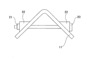
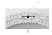
- FIG. 1 It is a perspective view which shows an example of the high-strength member of this invention. It is a side view which shows the state of the member tightened with a bolt and a nut in an Example. It is an enlarged view of the plate thickness center which is a measurement point, and the end face which shows the measurement direction in the measurement of the residual stress of the end face of an Example.
- the present invention is a high-strength member having a bent ridge line portion obtained by using a steel plate, the tensile strength of the member is 1470 MPa or more, the residual stress of the end face of the bent ridge line portion is 300 MPa or less, and the bending ridge line portion.
- the Vickers hardness (HV) of the end face is 200 or more and 450 or less.
- the steel plate used for the high-strength member is not particularly limited.
- a preferable steel sheet for obtaining the high-strength member of the present invention will be described, but the steel sheet used for the high-strength member of the present invention is not limited to the steel sheet described below.
- a preferable steel sheet for obtaining a high-strength member preferably has a component structure and a microstructure described later. If the high-strength member of the present invention can be obtained, it is not always necessary to use a steel sheet having a component composition and a microstructure described later.
- % which is a unit of the content of the component, means “mass%”.
- C is an element that improves hardenability.
- the C content is preferably 0.17% from the viewpoint of securing the total area ratio of one or two types of predetermined martensite and bainite, increasing the strength of martensite and bainite, and ensuring TS ⁇ 1470 MPa.
- the above is more preferably 0.18% or more, still more preferably 0.19% or more.
- the C content is preferably 0.35% or less, more preferably 0.33% or less, and further preferably 0.31% or less.
- Si is a strengthening element by solid solution strengthening. Further, Si contributes to the improvement of elongation by suppressing the excessive formation of coarse carbides when the steel sheet is held in a temperature range of 200 ° C. or higher. Further, it reduces Mn segregation at the central portion of the plate thickness, contributes to suppression of MnS formation, and improves delayed fracture resistance.
- the Si content is preferably 0.001% or more, more preferably 0.003% or more, and further preferably 0.005% or more.
- the Si content is preferably 1.2% or less, more preferably 1.1% or less, and even more preferably 1.0% or less.
- Mn 0.9% or more and 3.2% or less> Mn is contained to improve the hardenability of steel and to secure the total area ratio of one or two of predetermined martensite and bainite. If the Mn content is less than 0.9%, the strength may decrease due to the formation of ferrite on the surface layer of the steel sheet. Therefore, the Mn content is preferably 0.9% or more, more preferably 1.0% or more, and further preferably 1.1% or more. Further, the Mn content is preferably 3.2% or less, more preferably 3.1% or less, still more preferably 3.0% or less, so that MnS does not increase and the delayed fracture resistance is not deteriorated. Is.
- P is an element that reinforces steel, but if its content is large, the delayed fracture resistance deteriorates. Therefore, the P content is preferably 0.020% or less, more preferably 0.015% or less, and further preferably 0.010% or less.
- the lower limit of the P content is not particularly limited, but at present, the lower limit that can be industrially implemented is about 0.003%.
- S forms inclusions such as MnS, TiS, Ti (C, S).
- the S content is preferably 0.0010% or less in order to suppress deterioration of the delayed fracture resistance due to the inclusions.
- the S content is more preferably 0.0009% or less, further preferably 0.0007% or less, and particularly preferably 0.0005% or less.
- the lower limit of the S content is not particularly limited, but at present, the lower limit industrially feasible is about 0.0002%.
- Al 0.010% or more and 0.20% or less> Al is added to perform sufficient deoxidation and reduce coarse inclusions in the steel.
- the Al content is preferably 0.010% or more, more preferably 0.015% or more.
- the Al content exceeds 0.20%, Fe-based carbides such as cementite generated during winding after hot rolling are difficult to dissolve in the annealing process, resulting in coarse inclusions and carbides. May be generated, which may deteriorate the delayed fracture resistance. Therefore, the Al content is preferably 0.20% or less, more preferably 0.17% or less, and further preferably 0.15% or less.
- N is an element that forms nitrides such as TiN, (Nb, Ti) (C, N), and AlN, and coarse inclusions of carbon nitride system in steel, and the delayed fracture resistance deteriorates through the formation of these elements.
- the N content is preferably 0.010% or less, more preferably 0.007% or less, and further preferably 0.005% or less.
- the lower limit of the N content is not particularly limited, but at present, the lower limit industrially feasible is about 0.0006%.
- Sb suppresses oxidation and nitriding of the surface layer of the steel sheet, and suppresses decarburization by oxidation and nitriding of the surface of the steel sheet.
- the Sb content is preferably 0.001% or more, more preferably 0.002% or more, and further preferably 0.003% or more.
- the Sb content is preferably 0.10% or less, more preferably 0.08% or less, and further preferably 0.06% or less. It is preferable that Sb is contained, but if Sb is not contained and the effects of increasing the strength of the steel sheet and improving the delayed fracture resistance can be sufficiently obtained, Sb may not be contained.
- the preferred steel used for the high-strength member of the present invention preferably basically contains the above components, and the balance is iron and unavoidable impurities.
- the preferred steel used for the high-strength member of the present invention can contain the following optional elements as long as the action of the present invention is not impaired. If the following optional element is contained below the following lower limit, the optional element shall be included as an unavoidable impurity.
- B is an element that improves the hardenability of steel, and has an advantage of producing martensite and bainite having a predetermined area ratio even when the Mn content is low.
- the B content is preferably 0.0002% or more, more preferably 0.0005% or more, and further preferably 0.0007% or more. Further, from the viewpoint of fixing N, it is preferable to add 0.002% or more of Ti in combination.
- the B content is 0.0035% or more, the solid solution rate of cementite at the time of annealing is delayed, and carbides containing Fe as a main component such as unsolidified cementite remain, which results in coarseness. Deterioration of delayed fracture resistance due to the formation of various inclusions and carbides. Therefore, when B is contained, the B content is preferably less than 0.0035%, more preferably 0.0030% or less, still more preferably 0.0025% or less.
- Nb 0.002% or more and 0.08% or less
- Ti 0.002% or more and 0.12% or less>
- Nb and Ti contribute to high strength through miniaturization of old austenite ( ⁇ ) grains.
- the Nb content and the Ti content are preferably 0.002% or more, more preferably 0.003% or more, and further preferably 0.005% or more, respectively.
- Nb-based materials such as NbN, Nb (C, N), (Nb, Ti) (C, N) remaining unsolidified during slab heating in the hot rolling process
- Coarse precipitates and Ti-based coarse precipitates such as TiN, Ti (C, N), Ti (C, S), and TiS
- the delayed fracture resistance deteriorates. Therefore, when Nb is contained, the Nb content is preferably 0.08% or less, more preferably 0.06% or less, and further preferably 0.04% or less.
- Ti is contained, the Ti content is preferably 0.12% or less, more preferably 0.10% or less, and further preferably 0.08% or less.
- Cu and Ni have the effect of improving the corrosion resistance in the usage environment of automobiles and suppressing the invasion of hydrogen into the steel sheet by coating the surface of the steel sheet with corrosion products.
- Cu and Ni are preferably contained in an amount of 0.005% or more, more preferably 0.008% or more, respectively.
- the amount of Cu or Ni is too large, surface defects will occur and the plating property and chemical conversion treatment property will be deteriorated. Therefore, when at least one of Cu and Ni is contained, the Cu content and the Ni content are high.
- Each is preferably 1% or less, more preferably 0.8% or less, still more preferably 0.6% or less.
- ⁇ Cr 0.01% or more and 1.0% or less
- Mo 0.01% or more and less than 0.3%
- V 0.003% or more and 0.5% or less
- Zr 0.005% or more and 0.20 % Or less
- W at least one selected from 0.005% or more and 0.20% or less> Cr, Mo, and V can be contained for the purpose of improving the hardenability of steel.
- the Cr content and the Mo content are preferably 0.01% or more, more preferably 0.02% or more, and further preferably 0.03% or more, respectively. is there.
- the V content is preferably 0.003% or more, more preferably 0.005% or more, still more preferably 0.007% or more.
- the Cr content is preferably 1.0% or less, more preferably 0.4% or less, and further preferably 0.2% or less.
- Mo is contained
- the Mo content is preferably less than 0.3%, more preferably 0.2% or less, still more preferably 0.1% or less.
- V is contained, the V content is preferably 0.5% or less, more preferably 0.4% or less, and further preferably 0.3% or less.
- the Zr content and the W content are preferably 0.005% or more, more preferably 0.006% or more, and further preferably 0.007% or more, respectively.
- the Zr content and the W content are preferably 0.20% or less, more preferably 0.15% or less, and further preferably 0.15% or less, respectively. Is 0.10% or less.
- ⁇ Ca 0.0002% or more and 0.0030% or less
- Ce 0.0002% or more and 0.0030% or less
- La 0.0002% or more and 0.0030% or less
- Mg 0.0002% or more and 0.
- At least one selected from 0030% or less> Ca, Ce, and La contribute to the improvement of delayed fracture resistance by fixing S as a sulfide. Therefore, the content of each of these elements is preferably 0.0002% or more, more preferably 0.0003% or more, and further preferably 0.0005% or more.
- the content of each of these elements is preferably 0.0030% or less, more preferably 0.0020% or less, still more preferable. Is 0.0010% or less.
- the Mg content is preferably 0.0002% or more, more preferably 0.0003% or more, and further preferably 0.0005% or more.
- the Mg content is preferably 0.0030% or less, more preferably 0.0020% or less, and further preferably 0.0010% or less.
- Sn suppresses oxidation and nitriding of the surface layer of the steel sheet, and suppresses decarburization by oxidation and nitriding of the surface of the steel sheet. By suppressing decarburization, ferrite formation on the surface layer of the steel sheet is suppressed, which contributes to higher strength.
- the Sn content is preferably 0.002% or more, more preferably 0.003% or more, and further preferably 0.004% or more.
- Sn content is preferably 0.1% or less, more preferably 0.08% or less, and further preferably 0.06% or less.
- the total area ratio of one or two types of bainite containing carbides with an average particle size of 50 nm or less and martensite containing carbides with an average particle size of 50 nm or less is 90% or more>
- one or two types of bainite containing carbides having an average particle size of 50 nm or less and martensite containing carbides having an average particle size of 50 nm or less are used for the entire steel sheet structure.
- the total area ratio is preferably 90% or more. If it is less than this, the amount of ferrite increases and the strength decreases.
- the total area ratio is more preferably 91% or more, further preferably 92% or more, and particularly preferably 93% or more.
- the total area ratio may be 100% in total. Further, the area ratio of either one may be 90% or more, and the total area ratio of both may be 90% or more.
- Martensite does not include as-quenched martensite, but is tempered martensite.
- martensite refers to a hard structure formed from austenite at a low temperature (below the martensitic transformation point)
- tempered martensite refers to a structure that is tempered when martensite is reheated.
- Bainite refers to a hard structure formed from austenite at a relatively low temperature (above the martensitic transformation point) and in which fine carbides are dispersed in needle-shaped or plate-shaped ferrite.
- the residual structure other than martensite and bainite is ferrite, pearlite, and retained austenite, and the total amount is acceptable if it is less than 10%. It may be 0%.
- ferrite is a structure formed by transformation from austenite at a relatively high temperature and composed of crystal grains of a bcc lattice.
- Pearlite is a structure in which ferrite and cementite are formed in layers.
- Retained austenite is austenite that has not undergone martensitic transformation when the martensitic transformation temperature is below room temperature.
- the carbide having an average particle size of 50 nm or less in the present invention is a fine carbide that can be observed in bainite and martensite when observed by SEM.
- Specific examples of the carbides include Fe carbides, Ti carbides, V carbides, Mo carbides, W carbides, Nb carbides, and Zr carbides.
- the steel sheet may be provided with a plating layer such as a hot-dip galvanizing layer.
- a plating layer such as a hot-dip galvanizing layer.
- examples of such a plating layer include an electroplating layer, an electroless plating layer, and a hot-dip plating layer. Further, it may be used as an alloyed plating layer.
- the high-strength member of the present invention is a high-strength member having a bent ridge line portion obtained by using a steel plate, and the tensile strength of the member is 1470 MPa or more, and the residual stress of the end face of the bent ridge line portion is 300 MPa or less. Moreover, the Vickers hardness (HV) of the end face of the bent ridge line portion is 200 or more and 450 or less.
- the high-strength member of the present invention is obtained by using a steel plate, and is a molded member obtained by performing processing such as molding and bending so as to have a predetermined shape.
- the high-strength member of the present invention can be suitably used for, for example, automobile parts.
- the high-strength member of the present invention has a bent ridgeline portion.
- the "bent ridge portion" as used in the present invention refers to a region that is no longer a flat plate due to bending of a steel plate.
- An example of the high-strength member 10 shown in FIG. 1 is a steel plate 11 that has been V-bent.
- the high-strength member 10 has a bent ridge line portion 12 on the side surface of the steel plate 11 of the bent portion.
- the end surface 13 of the bent ridge line portion 12 is a plate thickness surface located on the side surface of the bent ridge line portion 12.
- the bending ridge line direction D1 in the present invention is a direction parallel to the bending ridge line portion 12.
- the bending angle is Not particularly limited.
- FIG. 1 An example of the high-strength member 10 shown in FIG. 1 shows an example in which one bent portion is formed, but it is assumed that two or more portions are bent and have two or more bent ridges. May be good.
- ⁇ Tensile strength of member is 1470 MPa or more>
- the tensile strength (TS) of the high-strength member is 1470 MPa or more.
- the tensile strength (TS) and yield strength (YS) in the present invention are calculated by measuring on a flat portion which is a non-bent portion of a high-strength member. Further, if the tensile strength (TS) and yield strength (YS) of the annealed steel sheet before bending (annealed steel sheet) are measured, these measured values are the high strengths obtained by using the annealed steel sheet. It can be regarded as a measured value of tensile strength (TS) and yield strength (YS) of a member.
- the strength of the member can be calculated by the method described in the examples.
- ⁇ Residual stress of the end face of the bent ridge is 300 MPa or less>
- the residual stress of the end surface (thick surface) of the bent ridge of the high-strength member is 300 MPa or less.
- the residual stress is 300 MPa or less, preferably 250 MPa or less, and more preferably 200 MPa or less.
- the lower limit is not particularly limited and may be a compressive stress.
- the residual stress of the end face of the bent ridge can be calculated by the method described in the examples of the present specification.
- ⁇ Vickers hardness (HV) of the end face of the bent ridge is 200 or more and 450 or less>
- the Vickers hardness (HV) of the end surface (thick surface) of the bent ridge of the high-strength member is 200 or more and 450 or less.
- the hardness is 450 or less, preferably 430 or less, and more preferably 400 or less.
- the Vickers hardness (HV) of the end face is set to 200 or more from the viewpoint of suppressing the occurrence of cracks due to delayed fracture and obtaining the strength of the member. It is preferably 220 or more, and more preferably 250 or more.
- the Vickers hardness of the end face of the bent ridge can be calculated by a method as described in the examples of the present specification.
- An example of the embodiment of the method for manufacturing a high-strength member of the present invention is a bending step of cutting out a steel sheet having a tensile strength of 1470 MPa or more and bending the steel sheet, and after bending the end face generated by the cutting. It has an end face treatment step of heating at a temperature of 400 ° C. or higher and 900 ° C. or lower under the conditions of more than 0 seconds and 10 seconds or less.
- another example of the embodiment of the method for manufacturing a high-strength member of the present invention is generated by a bending process of cutting out a steel sheet having the above component composition and the above microstructure and bending the steel sheet, and cutting. It has an end face treatment step of heating the end face at a temperature of 400 ° C. or higher and 900 ° C. or lower under the conditions of more than 0 seconds and 10 seconds or less after bending.
- the end face generated by the cutting is cut at a temperature of 400 ° C. or higher and 900 ° C. or lower for more than 0 seconds. It has an end face treatment step of heating under a condition of 10 seconds or less, and a bending step of bending a steel sheet after the end face treatment step.
- another example of the embodiment of the method for producing a high-strength member of the present invention is to cut out a steel sheet having the above-mentioned component composition and the above-mentioned microstructure, and then cut the end face generated by the cutting at a temperature of 400 ° C. or higher and 900 ° C. or lower. It has an end face treatment step of heating under conditions of more than 0 seconds and 10 seconds or less, and a bending step of bending a steel sheet after the end face treatment step.
- the method for manufacturing a high-strength member of the present invention is an end face treatment step in which a steel sheet is cut out and then the end face produced by the cutting is heated at a temperature of 400 ° C. or higher and 900 ° C. or lower under conditions of more than 0 seconds and 10 seconds or less.
- the steel sheet to be cut out is, for example, a steel sheet having a tensile strength of 1470 MPa or more.
- the steel sheet to be cut out is, for example, a steel sheet having the above-mentioned component composition and the above-mentioned microstructure.
- the cutting in the present invention means including known cutting such as shear cutting (mechanical cutting), laser cutting, electric cutting such as electric discharge machining, and gas cutting.
- the end face treatment step By performing the end face treatment step, the residual stress on the end face of the steel sheet is reduced, and by softening the end face, cracks are less likely to occur on the end face of the bent ridge line portion, and a member having excellent delayed fracture resistance can be obtained.
- the method for heating the end face is not particularly limited, and for example, there is heating by a laser.
- the end face of the molded member after bending the steel sheet is heated at a temperature of 400 ° C or higher and 900 ° C or lower.
- the heating temperature exceeds 900 ° C., the formation and coarsening of ferrite becomes remarkable, so that the strength of the molded member decreases, and the molded member becomes too soft, and the delayed fracture resistance also deteriorates. Therefore, the heating temperature is 900 ° C. or lower, preferably 870 ° C. or lower. Further, when the temperature is lower than 400 ° C., the heating capacity is insufficient and the tissue is not softened. Therefore, the heating temperature is 400 ° C. or higher. It is preferably 450 ° C.
- the heating time is 10 seconds or less. If the heating time exceeds 10 seconds, the structure becomes coarse and the delayed fracture resistance deteriorates. Therefore, the heating time is set to 10 seconds or less. It is preferably 9 seconds or less, more preferably 8 seconds or less.
- the structure may be softened and the Vickers hardness of the end face may be 200 or more and 450 or less, and the heating time is not particularly limited. Therefore, the heating time is more than 0 seconds, preferably 1 second or longer, and more preferably 2 seconds or longer.
- the heating range is not particularly limited, but in order to secure the strength of the molded member, it is preferably about 5 mm from the end face of the bent ridge line portion. Further, the heating direction is not particularly limited, but in order to eliminate temperature variation in the plate thickness direction, the direction perpendicular to the plate thickness surface is preferable.
- the method for manufacturing a high-strength member of the present invention includes a bending process for bending a steel sheet.
- the bending step may be performed before the end face treatment step or after the end face treatment step.
- the bending process of the present invention includes at least one of four deformation modes classified into, for example, bending deformation, deep drawing deformation, overhang deformation, and stretch flange deformation.
- a hot rolling step of hot rolling a steel (steel material) and a cold rolling of a hot-rolled steel plate obtained by hot rolling are performed.
- the average cooling rate in the temperature range from the annealing temperature to 550 ° C is 3 ° C / sec or more.
- temperatures shown below mean the surface temperatures of steel materials (slabs), steel plates, and the like.
- the casting speed is not particularly limited, but the casting speed is preferably 1.80 m / min or less, more preferably 1.75 m / min or less, in order to suppress the formation of the above-mentioned inclusions and improve the delayed fracture resistance. More preferably .70 m / min or less.
- the lower limit is not particularly limited, but from the viewpoint of productivity, it is preferably 1.25 m / min or more, and more preferably 1.30 m / min or more.
- the hot rolling step for example, a steel material (slab) having the above-mentioned composition is hot-rolled.
- the slab heating temperature is not particularly limited, but by setting the slab heating temperature to 1200 ° C. or higher, the solid solution of sulfide is promoted and the Mn segregation is reduced, the amount of coarse inclusions described above is reduced, and the delay tolerance is achieved. Destructive properties tend to improve. Therefore, the slab heating temperature is preferably 1200 ° C. or higher. More preferably, it is 1220 ° C. or higher.
- the heating rate during slab heating is preferably 5 to 15 ° C./min, and the slab heating time is preferably 30 to 100 minutes.
- the finish rolling end temperature is preferably 840 ° C or higher. If the finish rolling end temperature is less than 840 ° C., it takes time for the temperature to decrease, and inclusions may not only deteriorate the delayed fracture resistance but also deteriorate the internal quality of the steel sheet. Therefore, the finish rolling end temperature is preferably 840 ° C. or higher, more preferably 860 ° C. or higher. On the other hand, although the upper limit is not particularly limited, the finish rolling end temperature is preferably 950 ° C. or lower, more preferably 920 ° C. or lower, because it becomes difficult to cool down to the subsequent winding temperature.
- the cooled hot-rolled steel sheet is preferably wound at a temperature of 630 ° C. or lower. If the take-up temperature exceeds 630 ° C., the surface of the base iron may be decarburized, which may cause a structure difference between the inside and the surface of the steel sheet and cause uneven alloy concentration. Further, decarburization of the surface layer reduces the area ratio of bainite and martensite having carbides on the surface layer of the steel, so that it tends to be difficult to secure the desired strength. Therefore, the winding temperature is preferably 630 ° C. or lower, more preferably 600 ° C. or lower. The lower limit of the winding temperature is not particularly limited, but is preferably 500 ° C. or higher in order to prevent deterioration of cold rollability.
- the hot-rolled steel sheet obtained by hot rolling is cold-rolled.
- the hot-rolled steel sheet wound as described above is pickled and then cold-rolled to produce a cold-rolled steel sheet.
- the pickling conditions are not particularly limited. If the reduction rate is less than 20%, the flatness of the surface is poor and there is a risk that the structure becomes uneven. Therefore, the reduction rate is preferably 20% or more, more preferably 30% or more, and further. It is preferably 40% or more.
- the cold-rolled steel sheet obtained by cold rolling is heated to an annealing temperature of 3 points or more in AC. If the annealing temperature is less than 3 points AC, ferrite is formed in the structure and the desired strength cannot be obtained. Therefore, the annealing temperature is AC 3 points or more, preferably AC 3 points + 10 ° C. or higher, and more preferably AC 3 points + 20 ° C. or higher.
- the upper limit of the annealing temperature is not particularly limited, but the annealing temperature is preferably 900 ° C. or lower from the viewpoint of suppressing coarsening of austenite and preventing deterioration of delayed fracture resistance. After heating to an annealing temperature of 3 points or more in AC, the heating may be equalized at the annealing temperature.
- a C3 points are calculated by the following formula. Further, in the following formula, (% element symbol) means the content (mass%) of each element.
- AC 3 points (° C) 910-203 ⁇ (% C) +45 (% Si) -30 (% Mn) -20 (% Cu) -15 (% Ni) +11 (% Cr) +32 (% Mo) +104 ( % V) + 400 (% Ti) + 460 (% Al)
- the average cooling rate in the temperature range from the annealing temperature to 550 ° C is set to 3 ° C / sec or more, and the cooling stop temperature is set to 350 ° C or less. After that, it is held in a temperature range of 100 ° C. or higher and 260 ° C. or lower for 20 seconds or longer and 1500 seconds or shorter.
- the average cooling rate in the temperature range from the annealing temperature to 550 ° C is less than 3 ° C / sec, it becomes difficult to obtain the desired strength because it causes excessive formation of ferrite.
- the formation of ferrite on the surface layer makes it difficult to obtain a bainite or martensite fraction having carbides near the surface layer, which deteriorates the delayed fracture resistance. Therefore, the average cooling rate in the temperature range from the annealing temperature to 550 ° C. is 3 ° C./sec or more, preferably 5 ° C./sec or more, and more preferably 10 ° C./sec or more.
- the upper limit of the average cooling rate is not particularly specified, but if it is too fast, the martensitic transformation tends to be non-uniform in the coil width direction, and the steel sheet may come into contact with the equipment due to shape deterioration.
- the temperature is preferably 3000 ° C./s or less.
- the average cooling rate in the temperature range from the annealing temperature to 550 ° C is "(annealing temperature-550 ° C) / (cooling time from the annealing temperature to 550 ° C)".
- the cooling stop temperature is 350 ° C or less.
- the cooling stop temperature exceeds 350 ° C, tempering does not proceed sufficiently, martensite and retained austenite as hardened are generated in the final structure, and the hardness of the end face of the bent ridge increases, resulting in delayed fracture resistance. Deteriorates. Therefore, in order to obtain excellent delayed fracture resistance, the cooling stop temperature is 350 ° C. or lower, preferably 300 ° C. or lower, and more preferably 250 ° C. or lower.
- the lower limit of the cooling stop temperature is not particularly limited, it is preferably 0 ° C. or higher from the viewpoint of facilitating securing the temperature when reheating after that.
- the carbides distributed inside bainite are carbides that are generated during retention in the low temperature range after quenching, and by becoming hydrogen trap sites, hydrogen can be trapped and deterioration of delayed fracture resistance can be prevented.
- the holding temperature is less than 100 ° C. or the holding time is less than 20 seconds, bainite is not formed and hardened martensite containing no carbide is formed, so that the hardness of the end face of the bent ridge becomes high. , The above effect cannot be obtained.
- the holding temperature exceeds 260 ° C. or the holding time exceeds 1500 seconds, decarburization is performed and coarse carbides are generated inside the bainite, which causes the bainite to become too soft and deteriorate the delayed fracture resistance.
- the holding temperature is 100 ° C. or higher and 260 ° C. or lower, and the holding time is 20 seconds or longer and 1500 seconds or lower.
- the holding temperature is preferably 130 ° C. or higher and 240 ° C. or lower, and the holding time is preferably 50 seconds or longer and 1000 seconds or lower.
- the holding in the present invention includes not only holding at a constant temperature but also a case where the temperature changes within the holding temperature of the present invention.
- the hot-rolled steel sheet after hot rolling may be heat-treated to soften the structure. Further, the surface of the steel sheet may be plated with Zn, Al, or the like. Further, after annealing cooling or plating treatment, temper rolling for shape adjustment may be performed.
- Example 1 The steel sheet having the tensile strength shown in Table 1 was sheared into small pieces of 30 mm ⁇ 110 mm.
- JIS No. 5 test pieces with a distance between gauge points of 50 mm, a width between gauge points of 25 mm, and a plate thickness of 1.4 mm were collected from the rolling direction of the steel sheet, and in accordance with JISZ2241, the tensile speed was 10 mm / min.
- a tensile test was performed.
- the measured tensile strength (TS) and yield strength (YS) are shown in Table 1.
- TS measured tensile strength
- YiS yield strength
- Table 1 shows each condition of the end face treatment.
- the column of the heat treatment temperature (° C.) described as "-" means that the heat treatment was not performed.
- the critical load stress was measured by a delayed fracture test. Specifically, the members obtained under each production condition were immersed in hydrochloric acid having a pH of 1 (25 ° C.), and the maximum load stress that did not cause delayed fracture was evaluated as the critical load stress. The judgment of delayed fracture was performed visually and with an image magnified to a magnification of 20 with a stereomicroscope, and the case where the image was immersed for 96 hours and no cracks occurred was regarded as no destruction.
- the term “crack” as used herein refers to the case where a crack having a crack length of 200 ⁇ m or more occurs.
- FIG. 3 is an enlarged view of the end face of the bent ridge line portion, and is shown with reference numerals at the plate thickness center C1 and the measurement direction D2, respectively.
- the Vickers hardness (HV) of the end face was measured by the Vickers hardness test for the members obtained under each manufacturing condition.
- the Vickers hardness was measured at a position 100 ⁇ m from the end face at the center of the plate thickness of the cross section obtained by cutting the end face of the bent ridge line portion in the bending ridge line direction D1 direction and mirror-polishing the end face.
- the measured load was 1 kgf.
- a member having TS ⁇ 1470 MPa and critical load stress ⁇ 1.10 ⁇ YS was accepted, and is shown as an example of the invention in Table 1. Further, a member having TS ⁇ 1470 MPa or critical load stress ⁇ 1.10 ⁇ YS was rejected and is shown as a comparative example in Table 1.
- Table 1 when "critical load stress / YS" is 1.10 or more, it means that critical load stress ⁇ 1.10 ⁇ YS.
- the members of the examples of the present invention have high strength and excellent delayed fracture resistance.
- Example 2 1. Production of Evaluation Member A steel having the composition shown in Table 2 and having the balance of Fe and unavoidable impurities was melted in a vacuum melting furnace and then lump-rolled to obtain a lump-rolled material having a thickness of 27 mm. The obtained block-rolled material was hot-rolled to a thickness of 4.2 mm to produce a hot-rolled steel sheet. Next, the hot-rolled steel sheet was ground to a plate thickness of 3.2 mm and then cold-rolled to a plate thickness of 2.4 to 1.12 mm to produce a cold-rolled steel sheet. Next, the cold-rolled steel sheet obtained as described above was heat-treated under the conditions shown in Tables 3 and 4 (annealing step).
- the blanks in the component composition in Table 2 indicate that the component was not intentionally added, and include not only the case where the component is not contained (0% by mass) but also the case where the component is unavoidably contained. Details of each condition of the hot rolling step, the cold rolling step, and the annealing step are shown in Tables 3 and 4.
- the heat-treated steel sheet is sheared into small pieces of 30 mm x 110 mm, a sample of the steel sheet is placed on a die with an angle of 90 °, and the steel sheet is pressed with a punch with an angle of 90 ° to perform V-shaped bending.
- the bent steel plate member
- the relationship between the load stress and the tightening amount was calculated by CAE (Computer Aided Engineering) analysis, and the tightening amount and the critical load stress were made to match.
- the critical load stress was measured by the method described later.
- microstructure fraction was investigated by analyzing the steel structure (microstructure) of the members obtained under various manufacturing conditions.
- tensile properties such as tensile strength were evaluated by conducting a tensile test, and delayed fracture resistance was evaluated by the critical load stress measured by the delayed fracture test.
- the residual stress and Vickers hardness of the end face of the member were measured as follows. The method of each evaluation is as follows.
- a test piece is collected from the direction perpendicular to the steel sheet obtained in the annealing process (hereinafter referred to as annealed steel sheet), the plate thickness L cross section parallel to the rolling direction is mirror-polished, and the structure is revealed with a bainite solution.
- a 16 mm x 15 mm grid with 4.8 ⁇ m intervals is placed on a region with an actual length of 82 ⁇ m ⁇ 57 ⁇ m on an SEM image with a magnification of 1500 times, and points are counted on each phase.
- the area ratios of martensite containing carbides having an average particle size of 50 nm or less and bainite containing carbides having an average particle size of 50 nm or less were calculated, and the total area ratios thereof were calculated.
- the area ratio was the average value of the three area ratios obtained from separate SEM images at a magnification of 1500 times.
- Martensite has a white structure
- bainite has fine carbides precipitated inside the black structure.
- the average particle size of the carbide was calculated as follows.
- the area ratio is the area ratio with respect to the entire observation range, and this is regarded as the area ratio with respect to the entire steel sheet structure.
- the critical load stress was measured by a delayed fracture test. Specifically, the members obtained under each production condition were immersed in hydrochloric acid having a pH of 1 (25 ° C.), and the maximum load stress that did not cause delayed fracture was evaluated as the critical load stress. The judgment of delayed fracture was performed visually and with an image magnified to a magnification of 20 with a stereomicroscope, and the case where the image was immersed for 96 hours and no cracks occurred was regarded as no destruction.
- the term “crack” as used herein refers to the case where a crack having a crack length of 200 ⁇ m or more occurs.
- FIG. 3 is an enlarged view of the end face of the bent ridge line portion, and is shown with reference numerals at the plate thickness center C1 and the measurement direction D2, respectively.
- the Vickers hardness (HV) of the end face was measured by the Vickers hardness test for the members obtained under each manufacturing condition.
- the Vickers hardness was measured at a position 100 ⁇ m from the end face at the center of the plate thickness of the cross section obtained by cutting the end face of the bent ridge line portion in the bending ridge line direction D1 direction and mirror-polishing the end face.
- the measured load was 1 kgf.
- a member having TS ⁇ 1470 MPa and critical load stress ⁇ 1.10 ⁇ YS was accepted, and is shown as an example of invention in Tables 5 and 6. Further, the members having TS ⁇ 1470 MPa or critical load stress ⁇ 1.10 ⁇ YS were rejected and are shown as comparative examples in Tables 5 and 6.
- Tables 5 and 6 when "critical load stress / YS" is 1.10 or more, it means that critical load stress ⁇ 1.10 ⁇ YS.
- the members of the examples of the present invention have high strength and excellent delayed fracture resistance.
- Example 3 In Example 3, a member was manufactured and evaluated with a steel grade containing no Sb. 1.
- a steel having the composition shown in Table 7 and having the balance of Fe and unavoidable impurities was melted in a vacuum melting furnace and then lump-rolled to obtain a lump-rolled material having a thickness of 27 mm.
- the obtained block-rolled material was hot-rolled to a thickness of 4.2 mm to produce a hot-rolled steel sheet.
- the hot-rolled steel sheet was ground to a plate thickness of 3.2 mm and then cold-rolled to a plate thickness of 2.4 to 1.12 mm to produce a cold-rolled steel sheet.
- the cold-rolled steel sheet obtained as described above was heat-treated under the conditions shown in Table 8 (annealing step).
- the blanks in the component composition in Table 7 indicate that the component was not intentionally added, and include not only the case where the component is not intentionally added (0% by mass) but also the case where the component is unavoidably contained.
- the details of each condition of the hot rolling step, the cold rolling step, and the annealing step are shown in Table 8.
- the heat-treated steel sheet is sheared into small pieces of 30 mm x 110 mm, a sample of the steel sheet is placed on a die with an angle of 90 °, and the steel sheet is pressed with a punch with an angle of 90 ° to perform V-shaped bending.
- the bent steel plate member
- the relationship between the load stress and the tightening amount was calculated by CAE (Computer Aided Engineering) analysis, and the tightening amount and the critical load stress were made to match.
- the critical load stress was measured by the method described in Example 2.
- a member having TS ⁇ 1470 MPa and critical load stress ⁇ 1.10 ⁇ YS was accepted, and is shown as an example of invention in Table 9. Further, a member having TS ⁇ 1470 MPa or critical load stress ⁇ 1.10 ⁇ YS was rejected and is shown as a comparative example in Table 9.
- Table 9 when "critical load stress / YS" is 1.10 or more, it means that critical load stress ⁇ 1.10 ⁇ YS.
- the members of the examples of the present invention have high strength and excellent delayed fracture resistance.
Landscapes
- Chemical & Material Sciences (AREA)
- Engineering & Computer Science (AREA)
- Mechanical Engineering (AREA)
- Materials Engineering (AREA)
- Metallurgy (AREA)
- Organic Chemistry (AREA)
- Physics & Mathematics (AREA)
- Thermal Sciences (AREA)
- Crystallography & Structural Chemistry (AREA)
- Health & Medical Sciences (AREA)
- Child & Adolescent Psychology (AREA)
- Heat Treatment Of Sheet Steel (AREA)
- Heat Treatment Of Articles (AREA)
- Bending Of Plates, Rods, And Pipes (AREA)
Priority Applications (6)
| Application Number | Priority Date | Filing Date | Title |
|---|---|---|---|
| CN202080035625.5A CN113840934B (zh) | 2019-05-16 | 2020-05-12 | 高强度构件、高强度构件的制造方法和高强度构件用钢板的制造方法 |
| MX2021013945A MX2021013945A (es) | 2019-05-16 | 2020-05-12 | Miembro de alta resistencia, metodo para la fabricacion de miembro de alta resistencia, y metodo para la fabricacion de lamina de acero para miembro de alta resistencia. |
| JP2020545826A JP6950835B2 (ja) | 2019-05-16 | 2020-05-12 | 高強度部材、高強度部材の製造方法及び高強度部材用鋼板の製造方法 |
| US17/610,483 US12454733B2 (en) | 2019-05-16 | 2020-05-12 | High strength member, method for manufacturing high strength member, and method for manufacturing steel sheet for high strength member |
| EP20805261.3A EP3971308B1 (en) | 2019-05-16 | 2020-05-12 | High strength member, method for manufacturing high strength member, and method for manufacturing steel sheet for high strength member |
| KR1020217036919A KR102654714B1 (ko) | 2019-05-16 | 2020-05-12 | 고강도 부재, 고강도 부재의 제조 방법 및 고강도 부재용 강판의 제조 방법 |
Applications Claiming Priority (4)
| Application Number | Priority Date | Filing Date | Title |
|---|---|---|---|
| JP2019-092656 | 2019-05-16 | ||
| JP2019092656 | 2019-05-16 | ||
| JP2019121144 | 2019-06-28 | ||
| JP2019-121144 | 2019-06-28 |
Publications (1)
| Publication Number | Publication Date |
|---|---|
| WO2020230796A1 true WO2020230796A1 (ja) | 2020-11-19 |
Family
ID=73289458
Family Applications (1)
| Application Number | Title | Priority Date | Filing Date |
|---|---|---|---|
| PCT/JP2020/019021 Ceased WO2020230796A1 (ja) | 2019-05-16 | 2020-05-12 | 高強度部材、高強度部材の製造方法及び高強度部材用鋼板の製造方法 |
Country Status (7)
| Country | Link |
|---|---|
| US (1) | US12454733B2 (enExample) |
| EP (1) | EP3971308B1 (enExample) |
| JP (3) | JP6950835B2 (enExample) |
| KR (1) | KR102654714B1 (enExample) |
| CN (1) | CN113840934B (enExample) |
| MX (1) | MX2021013945A (enExample) |
| WO (1) | WO2020230796A1 (enExample) |
Cited By (6)
| Publication number | Priority date | Publication date | Assignee | Title |
|---|---|---|---|---|
| JP7004126B1 (ja) * | 2020-12-03 | 2022-01-21 | Jfeスチール株式会社 | 遅れ破壊特性評価方法、及びプログラム |
| JP7111281B1 (ja) * | 2021-03-02 | 2022-08-02 | Jfeスチール株式会社 | 鋼板、部材およびそれらの製造方法 |
| JP7111280B1 (ja) * | 2021-03-02 | 2022-08-02 | Jfeスチール株式会社 | 鋼板、部材およびそれらの製造方法 |
| WO2022185805A1 (ja) * | 2021-03-02 | 2022-09-09 | Jfeスチール株式会社 | 鋼板、部材およびそれらの製造方法 |
| WO2022185804A1 (ja) * | 2021-03-02 | 2022-09-09 | Jfeスチール株式会社 | 鋼板、部材およびそれらの製造方法 |
| WO2025070760A1 (ja) * | 2023-09-28 | 2025-04-03 | 日本製鉄株式会社 | 成形体 |
Families Citing this family (6)
| Publication number | Priority date | Publication date | Assignee | Title |
|---|---|---|---|---|
| KR20230089785A (ko) * | 2021-12-14 | 2023-06-21 | 주식회사 포스코 | 굽힘 특성이 우수한 초고강도 강판 및 이의 제조방법 |
| KR20240052137A (ko) * | 2022-10-13 | 2024-04-23 | 주식회사 포스코 | 굽힘 특성이 우수한 초고강도 강판 및 이의 제조방법 |
| KR20250093734A (ko) * | 2023-12-15 | 2025-06-25 | 주식회사 포스코 | 냉연강판 및 그 제조방법 |
| JP2025112825A (ja) * | 2024-01-22 | 2025-08-01 | トヨタ自動車株式会社 | 衝撃吸収部品の製造方法、及び衝撃吸収部品 |
| CN118086782B (zh) * | 2024-04-28 | 2024-07-16 | 江苏永钢集团有限公司 | 一种8.8级非调型螺栓用高塑性热轧盘条及其制造方法 |
| CN119040765B (zh) * | 2024-09-02 | 2025-10-24 | 河北鑫途紧固件制造有限公司 | 耐腐蚀地脚螺栓 |
Citations (6)
| Publication number | Priority date | Publication date | Assignee | Title |
|---|---|---|---|---|
| JP2003166035A (ja) | 2001-11-28 | 2003-06-13 | Nippon Steel Corp | 成形加工後の耐遅れ破壊性に優れた高強度薄鋼板及びその製造方法並びに高強度薄鋼板により作成された自動車用強度部品 |
| US20120060982A1 (en) * | 2010-03-12 | 2012-03-15 | Benteler Automobiltechnik Gmbh | Method of producing press-hardened structural parts |
| JP2012157902A (ja) * | 2011-01-14 | 2012-08-23 | Amada Co Ltd | 板材の折曲げ加工方法及び残留応力増減装置 |
| WO2016152163A1 (ja) * | 2015-03-25 | 2016-09-29 | Jfeスチール株式会社 | 冷延鋼板およびその製造方法 |
| JP2017125228A (ja) | 2016-01-13 | 2017-07-20 | Jfeスチール株式会社 | 成形部材の製造方法 |
| JP2017226901A (ja) * | 2016-06-24 | 2017-12-28 | 東洋スチール株式会社 | 高張力鋼板の絞り加工品の置き割れ防止方法 |
Family Cites Families (4)
| Publication number | Priority date | Publication date | Assignee | Title |
|---|---|---|---|---|
| EP2738280B1 (en) | 2011-07-29 | 2019-03-20 | Nippon Steel & Sumitomo Metal Corporation | High-strength galvanized steel sheet having superior bendability and method for producing same |
| WO2017138504A1 (ja) | 2016-02-10 | 2017-08-17 | Jfeスチール株式会社 | 高強度鋼板及びその製造方法 |
| JP6296214B1 (ja) * | 2016-08-10 | 2018-03-20 | Jfeスチール株式会社 | 薄鋼板およびその製造方法 |
| MX2021004419A (es) * | 2018-10-18 | 2021-07-06 | Jfe Steel Corp | Lamina de acero electrogalvanizada de alta resistencia y alto limite de alargamiento y metodo para la fabricacion de la misma. |
-
2020
- 2020-05-12 US US17/610,483 patent/US12454733B2/en active Active
- 2020-05-12 MX MX2021013945A patent/MX2021013945A/es unknown
- 2020-05-12 JP JP2020545826A patent/JP6950835B2/ja active Active
- 2020-05-12 KR KR1020217036919A patent/KR102654714B1/ko active Active
- 2020-05-12 CN CN202080035625.5A patent/CN113840934B/zh active Active
- 2020-05-12 EP EP20805261.3A patent/EP3971308B1/en active Active
- 2020-05-12 WO PCT/JP2020/019021 patent/WO2020230796A1/ja not_active Ceased
-
2021
- 2021-07-28 JP JP2021123186A patent/JP7736476B2/ja active Active
-
2024
- 2024-08-20 JP JP2024138387A patent/JP2024164841A/ja not_active Withdrawn
Patent Citations (6)
| Publication number | Priority date | Publication date | Assignee | Title |
|---|---|---|---|---|
| JP2003166035A (ja) | 2001-11-28 | 2003-06-13 | Nippon Steel Corp | 成形加工後の耐遅れ破壊性に優れた高強度薄鋼板及びその製造方法並びに高強度薄鋼板により作成された自動車用強度部品 |
| US20120060982A1 (en) * | 2010-03-12 | 2012-03-15 | Benteler Automobiltechnik Gmbh | Method of producing press-hardened structural parts |
| JP2012157902A (ja) * | 2011-01-14 | 2012-08-23 | Amada Co Ltd | 板材の折曲げ加工方法及び残留応力増減装置 |
| WO2016152163A1 (ja) * | 2015-03-25 | 2016-09-29 | Jfeスチール株式会社 | 冷延鋼板およびその製造方法 |
| JP2017125228A (ja) | 2016-01-13 | 2017-07-20 | Jfeスチール株式会社 | 成形部材の製造方法 |
| JP2017226901A (ja) * | 2016-06-24 | 2017-12-28 | 東洋スチール株式会社 | 高張力鋼板の絞り加工品の置き割れ防止方法 |
Non-Patent Citations (1)
| Title |
|---|
| See also references of EP3971308A4 |
Cited By (9)
| Publication number | Priority date | Publication date | Assignee | Title |
|---|---|---|---|---|
| JP7004126B1 (ja) * | 2020-12-03 | 2022-01-21 | Jfeスチール株式会社 | 遅れ破壊特性評価方法、及びプログラム |
| JP7111281B1 (ja) * | 2021-03-02 | 2022-08-02 | Jfeスチール株式会社 | 鋼板、部材およびそれらの製造方法 |
| JP7111280B1 (ja) * | 2021-03-02 | 2022-08-02 | Jfeスチール株式会社 | 鋼板、部材およびそれらの製造方法 |
| WO2022185805A1 (ja) * | 2021-03-02 | 2022-09-09 | Jfeスチール株式会社 | 鋼板、部材およびそれらの製造方法 |
| WO2022185804A1 (ja) * | 2021-03-02 | 2022-09-09 | Jfeスチール株式会社 | 鋼板、部材およびそれらの製造方法 |
| EP4283007A4 (en) * | 2021-03-02 | 2024-07-31 | JFE Steel Corporation | STEEL SHEET, ELEMENT, METHOD FOR PRODUCING THE STEEL SHEET AND METHOD FOR PRODUCING SAID ELEMENT |
| EP4283006A4 (en) * | 2021-03-02 | 2024-08-07 | JFE Steel Corporation | Steel sheet, member, method for producing said steel sheet, and method for producing said member |
| WO2025070760A1 (ja) * | 2023-09-28 | 2025-04-03 | 日本製鉄株式会社 | 成形体 |
| JPWO2025070760A1 (enExample) * | 2023-09-28 | 2025-04-03 |
Also Published As
| Publication number | Publication date |
|---|---|
| KR20210149841A (ko) | 2021-12-09 |
| JP7736476B2 (ja) | 2025-09-09 |
| EP3971308A4 (en) | 2022-06-15 |
| EP3971308B1 (en) | 2024-08-07 |
| JP2021181625A (ja) | 2021-11-25 |
| JP6950835B2 (ja) | 2021-10-13 |
| JPWO2020230796A1 (ja) | 2021-05-20 |
| KR102654714B1 (ko) | 2024-04-04 |
| MX2021013945A (es) | 2022-01-04 |
| JP2024164841A (ja) | 2024-11-27 |
| US20220220577A1 (en) | 2022-07-14 |
| CN113840934A (zh) | 2021-12-24 |
| EP3971308A1 (en) | 2022-03-23 |
| US12454733B2 (en) | 2025-10-28 |
| CN113840934B (zh) | 2022-10-28 |
Similar Documents
| Publication | Publication Date | Title |
|---|---|---|
| JP6950835B2 (ja) | 高強度部材、高強度部材の製造方法及び高強度部材用鋼板の製造方法 | |
| JP6729835B1 (ja) | 高強度鋼板およびその製造方法 | |
| WO2017179372A1 (ja) | 高強度鋼板およびその製造方法 | |
| JP7701864B2 (ja) | 高強度部材および高強度部材の製造方法 | |
| JP6958752B2 (ja) | 鋼板、部材及びそれらの製造方法 | |
| JP5316025B2 (ja) | 熱間打抜き性に優れたダイクエンチ用鋼板 | |
| KR20240139067A (ko) | 강판, 부재, 그들의 제조 방법, 냉연 강판용 열연 강판의 제조 방법 및 냉연 강판의 제조 방법 | |
| JP5316027B2 (ja) | 熱間打抜き性に優れたダイクエンチ用鋼板 | |
| JP5316028B2 (ja) | 熱間打抜き性に優れたダイクエンチ用鋼板 | |
| KR20240139068A (ko) | 강판, 부재, 그들의 제조 방법, 냉연 강판용 열연 강판의 제조 방법 및 냉연 강판의 제조 방법 | |
| JP5316026B2 (ja) | 熱間打抜き性に優れたダイクエンチ用鋼板 | |
| JP2010174295A (ja) | 熱間打抜き性に優れたダイクエンチ用鋼板 |
Legal Events
| Date | Code | Title | Description |
|---|---|---|---|
| ENP | Entry into the national phase |
Ref document number: 2020545826 Country of ref document: JP Kind code of ref document: A |
|
| 121 | Ep: the epo has been informed by wipo that ep was designated in this application |
Ref document number: 20805261 Country of ref document: EP Kind code of ref document: A1 |
|
| ENP | Entry into the national phase |
Ref document number: 20217036919 Country of ref document: KR Kind code of ref document: A |
|
| NENP | Non-entry into the national phase |
Ref country code: DE |
|
| WWE | Wipo information: entry into national phase |
Ref document number: 2020805261 Country of ref document: EP |
|
| ENP | Entry into the national phase |
Ref document number: 2020805261 Country of ref document: EP Effective date: 20211216 |
|
| WWG | Wipo information: grant in national office |
Ref document number: 17610483 Country of ref document: US |