WO2020230308A1 - Driving assistance method and driving assistance device - Google Patents
Driving assistance method and driving assistance device Download PDFInfo
- Publication number
- WO2020230308A1 WO2020230308A1 PCT/JP2019/019398 JP2019019398W WO2020230308A1 WO 2020230308 A1 WO2020230308 A1 WO 2020230308A1 JP 2019019398 W JP2019019398 W JP 2019019398W WO 2020230308 A1 WO2020230308 A1 WO 2020230308A1
- Authority
- WO
- WIPO (PCT)
- Prior art keywords
- mode
- lane
- steering wheel
- vehicle
- hands
- Prior art date
Links
Images


Classifications
-
- B—PERFORMING OPERATIONS; TRANSPORTING
- B60—VEHICLES IN GENERAL
- B60W—CONJOINT CONTROL OF VEHICLE SUB-UNITS OF DIFFERENT TYPE OR DIFFERENT FUNCTION; CONTROL SYSTEMS SPECIALLY ADAPTED FOR HYBRID VEHICLES; ROAD VEHICLE DRIVE CONTROL SYSTEMS FOR PURPOSES NOT RELATED TO THE CONTROL OF A PARTICULAR SUB-UNIT
- B60W60/00—Drive control systems specially adapted for autonomous road vehicles
- B60W60/005—Handover processes
- B60W60/0053—Handover processes from vehicle to occupant
- B60W60/0055—Handover processes from vehicle to occupant only part of driving tasks shifted to occupants
-
- G—PHYSICS
- G08—SIGNALLING
- G08G—TRAFFIC CONTROL SYSTEMS
- G08G1/00—Traffic control systems for road vehicles
- G08G1/16—Anti-collision systems
- G08G1/161—Decentralised systems, e.g. inter-vehicle communication
-
- B—PERFORMING OPERATIONS; TRANSPORTING
- B60—VEHICLES IN GENERAL
- B60W—CONJOINT CONTROL OF VEHICLE SUB-UNITS OF DIFFERENT TYPE OR DIFFERENT FUNCTION; CONTROL SYSTEMS SPECIALLY ADAPTED FOR HYBRID VEHICLES; ROAD VEHICLE DRIVE CONTROL SYSTEMS FOR PURPOSES NOT RELATED TO THE CONTROL OF A PARTICULAR SUB-UNIT
- B60W30/00—Purposes of road vehicle drive control systems not related to the control of a particular sub-unit, e.g. of systems using conjoint control of vehicle sub-units, or advanced driver assistance systems for ensuring comfort, stability and safety or drive control systems for propelling or retarding the vehicle
- B60W30/10—Path keeping
- B60W30/12—Lane keeping
-
- B—PERFORMING OPERATIONS; TRANSPORTING
- B60—VEHICLES IN GENERAL
- B60W—CONJOINT CONTROL OF VEHICLE SUB-UNITS OF DIFFERENT TYPE OR DIFFERENT FUNCTION; CONTROL SYSTEMS SPECIALLY ADAPTED FOR HYBRID VEHICLES; ROAD VEHICLE DRIVE CONTROL SYSTEMS FOR PURPOSES NOT RELATED TO THE CONTROL OF A PARTICULAR SUB-UNIT
- B60W30/00—Purposes of road vehicle drive control systems not related to the control of a particular sub-unit, e.g. of systems using conjoint control of vehicle sub-units, or advanced driver assistance systems for ensuring comfort, stability and safety or drive control systems for propelling or retarding the vehicle
- B60W30/14—Adaptive cruise control
- B60W30/16—Control of distance between vehicles, e.g. keeping a distance to preceding vehicle
-
- B—PERFORMING OPERATIONS; TRANSPORTING
- B60—VEHICLES IN GENERAL
- B60W—CONJOINT CONTROL OF VEHICLE SUB-UNITS OF DIFFERENT TYPE OR DIFFERENT FUNCTION; CONTROL SYSTEMS SPECIALLY ADAPTED FOR HYBRID VEHICLES; ROAD VEHICLE DRIVE CONTROL SYSTEMS FOR PURPOSES NOT RELATED TO THE CONTROL OF A PARTICULAR SUB-UNIT
- B60W30/00—Purposes of road vehicle drive control systems not related to the control of a particular sub-unit, e.g. of systems using conjoint control of vehicle sub-units, or advanced driver assistance systems for ensuring comfort, stability and safety or drive control systems for propelling or retarding the vehicle
- B60W30/18—Propelling the vehicle
- B60W30/18009—Propelling the vehicle related to particular drive situations
- B60W30/18163—Lane change; Overtaking manoeuvres
-
- B—PERFORMING OPERATIONS; TRANSPORTING
- B60—VEHICLES IN GENERAL
- B60W—CONJOINT CONTROL OF VEHICLE SUB-UNITS OF DIFFERENT TYPE OR DIFFERENT FUNCTION; CONTROL SYSTEMS SPECIALLY ADAPTED FOR HYBRID VEHICLES; ROAD VEHICLE DRIVE CONTROL SYSTEMS FOR PURPOSES NOT RELATED TO THE CONTROL OF A PARTICULAR SUB-UNIT
- B60W60/00—Drive control systems specially adapted for autonomous road vehicles
- B60W60/005—Handover processes
- B60W60/0053—Handover processes from vehicle to occupant
-
- B—PERFORMING OPERATIONS; TRANSPORTING
- B60—VEHICLES IN GENERAL
- B60W—CONJOINT CONTROL OF VEHICLE SUB-UNITS OF DIFFERENT TYPE OR DIFFERENT FUNCTION; CONTROL SYSTEMS SPECIALLY ADAPTED FOR HYBRID VEHICLES; ROAD VEHICLE DRIVE CONTROL SYSTEMS FOR PURPOSES NOT RELATED TO THE CONTROL OF A PARTICULAR SUB-UNIT
- B60W60/00—Drive control systems specially adapted for autonomous road vehicles
- B60W60/005—Handover processes
- B60W60/0057—Estimation of the time available or required for the handover
-
- B—PERFORMING OPERATIONS; TRANSPORTING
- B60—VEHICLES IN GENERAL
- B60W—CONJOINT CONTROL OF VEHICLE SUB-UNITS OF DIFFERENT TYPE OR DIFFERENT FUNCTION; CONTROL SYSTEMS SPECIALLY ADAPTED FOR HYBRID VEHICLES; ROAD VEHICLE DRIVE CONTROL SYSTEMS FOR PURPOSES NOT RELATED TO THE CONTROL OF A PARTICULAR SUB-UNIT
- B60W2552/00—Input parameters relating to infrastructure
- B60W2552/05—Type of road
-
- B—PERFORMING OPERATIONS; TRANSPORTING
- B60—VEHICLES IN GENERAL
- B60W—CONJOINT CONTROL OF VEHICLE SUB-UNITS OF DIFFERENT TYPE OR DIFFERENT FUNCTION; CONTROL SYSTEMS SPECIALLY ADAPTED FOR HYBRID VEHICLES; ROAD VEHICLE DRIVE CONTROL SYSTEMS FOR PURPOSES NOT RELATED TO THE CONTROL OF A PARTICULAR SUB-UNIT
- B60W2552/00—Input parameters relating to infrastructure
- B60W2552/30—Road curve radius
-
- B—PERFORMING OPERATIONS; TRANSPORTING
- B60—VEHICLES IN GENERAL
- B60W—CONJOINT CONTROL OF VEHICLE SUB-UNITS OF DIFFERENT TYPE OR DIFFERENT FUNCTION; CONTROL SYSTEMS SPECIALLY ADAPTED FOR HYBRID VEHICLES; ROAD VEHICLE DRIVE CONTROL SYSTEMS FOR PURPOSES NOT RELATED TO THE CONTROL OF A PARTICULAR SUB-UNIT
- B60W2556/00—Input parameters relating to data
- B60W2556/40—High definition maps
-
- B—PERFORMING OPERATIONS; TRANSPORTING
- B60—VEHICLES IN GENERAL
- B60W—CONJOINT CONTROL OF VEHICLE SUB-UNITS OF DIFFERENT TYPE OR DIFFERENT FUNCTION; CONTROL SYSTEMS SPECIALLY ADAPTED FOR HYBRID VEHICLES; ROAD VEHICLE DRIVE CONTROL SYSTEMS FOR PURPOSES NOT RELATED TO THE CONTROL OF A PARTICULAR SUB-UNIT
- B60W2720/00—Output or target parameters relating to overall vehicle dynamics
- B60W2720/10—Longitudinal speed
-
- B—PERFORMING OPERATIONS; TRANSPORTING
- B60—VEHICLES IN GENERAL
- B60W—CONJOINT CONTROL OF VEHICLE SUB-UNITS OF DIFFERENT TYPE OR DIFFERENT FUNCTION; CONTROL SYSTEMS SPECIALLY ADAPTED FOR HYBRID VEHICLES; ROAD VEHICLE DRIVE CONTROL SYSTEMS FOR PURPOSES NOT RELATED TO THE CONTROL OF A PARTICULAR SUB-UNIT
- B60W2720/00—Output or target parameters relating to overall vehicle dynamics
- B60W2720/12—Lateral speed
- B60W2720/125—Lateral acceleration
-
- G—PHYSICS
- G08—SIGNALLING
- G08G—TRAFFIC CONTROL SYSTEMS
- G08G1/00—Traffic control systems for road vehicles
- G08G1/16—Anti-collision systems
- G08G1/167—Driving aids for lane monitoring, lane changing, e.g. blind spot detection
Definitions
- This disclosure relates to a driving support method and a driving support device.
- This disclosure focuses on the above issues, and in a driving scene in a mode in which the driving support level is raised, the driving support level is gradually lowered when the steering wheel support release is grasped in advance.
- the purpose is to make the transfer from the driver to the driver more reliably.
- the present disclosure is a driving support method using a mode transition controller that has a vehicle speed / inter-vehicle distance control function and a lane keeping function as driving support functions for assisting a driver's driving operation and transitions to a driving support mode.
- the driving support modes include a hands-off mode that allows the driver to take his hand off the steering wheel, a steering wheel grip mode that requires the driver to hold the steering wheel with his hand, and a steering wheel support release mode that cancels the lane keeping function.
- a lane disappearance area where continuous lanes cannot be recognized from the own lane is detected on the extension of the driving route of the own vehicle.
- the mode transition position is set between the own vehicle position and the lane disappearance start point.
- the mode transition from the hands-off mode to the steering wheel gripping mode is requested.
- the mode transitions from the steering wheel gripping mode to the steering wheel support release mode by the time the vehicle reaches the lane disappearance start point.
- the driving support method and the driving support device in the first embodiment are applied to a driving support vehicle equipped with an advanced driving support system ADAS (abbreviation of "Advanced Driver Assistance Systems”) that supports the driving operation of the driver.
- ADAS Advanced Driver Assistance Systems
- the configuration of the first embodiment will be described separately as “overall system configuration”, “mode transition controller control block configuration”, and “driving support mode switching control processing configuration”.
- FIG. 1 shows an advanced driving support system to which the driving support method and the driving support device of the first embodiment are applied.
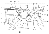
- FIG. 2 shows the vehicle interior configuration when the front window is viewed from the driver's seat position of the driving support vehicle.
- FIG. 3 shows an operation switch by a driver provided on the steering wheel of a driving support vehicle.
- the advanced driver assistance system ADAS is a system that has a vehicle speed / inter-vehicle distance control function, a lane keeping function, and a route driving support function. Then, as shown in FIG. 1, an in-vehicle sensor 1, a map data storage unit 2, an external data communication device 3, an ADAS control unit 4, an actuator 5, an HMI device 6, a navigation system 7, and an operation switch are used. 8 and control information sensors 9 are provided.
- HMI is an abbreviation for "Human Machine Interface”.
- the in-vehicle sensor 1 includes a camera 11, a radar 12, a GPS 13, and an in-vehicle data communication device 14.
- the sensor information acquired by the in-vehicle sensor 1 is output to the ADAS control unit 4.
- the camera 11 is a vehicle surrounding recognition sensor that realizes a function of acquiring information on the surroundings of the vehicle such as the vehicle's lane, adjacent lanes, vehicles around the vehicle, and pedestrians around the vehicle from image data.
- the camera 11 is configured to have an around view monitor function by combining a front recognition camera, a rear recognition camera, a right recognition camera, a left recognition camera, and the like.
- the vehicle's on-road object, lane, own vehicle's off-road object road structure, preceding vehicle, following vehicle, oncoming vehicle, surrounding vehicle, pedestrian, bicycle, two-wheeled vehicle
- own vehicle's driving road (road) White lines, road boundaries, stop lines, pedestrian crossings), road signs (speed limit), etc.
- the radar 12 is a distance measuring sensor that realizes a function of detecting the presence of an object around the vehicle and a function of detecting the distance to an object around the vehicle.
- radar 12 is a general term including a radar using radio waves, a rider using light, and a sonar using ultrasonic waves.
- the radar 12 detects the positions of objects on the vehicle's road and objects outside the vehicle's road (road structures, preceding vehicles, following vehicles, oncoming vehicles, surrounding vehicles, pedestrians, bicycles, motorcycles), and at the same time. The distance to each object is detected.
- GPS 13 is a vehicle position sensor that has a GNSS antenna 13a and detects the vehicle position (latitude / longitude) while the vehicle is stopped / running by using satellite communication.
- GNSS is an abbreviation for "Global Navigation Satellite System”
- GPS is an abbreviation for "Global Positioning System”.
- the in-vehicle data communication device 14 performs wireless communication with the external data communication device 3 via the transmission / reception antennas 3a and 14a to acquire information that cannot be acquired by the in-vehicle sensor 1 or map data from the outside. It is a data sensor.
- the "external data communication device 3" is, for example, a data communication device mounted on another vehicle traveling around the own vehicle, vehicle-to-vehicle communication is performed between the own vehicle and the other vehicle, and the other vehicle performs inter-vehicle communication.
- the "external data communication device 3" is, for example, a data communication device mounted on another vehicle traveling around the own vehicle, vehicle-to-vehicle communication is performed between the own vehicle and the other vehicle, and the other vehicle performs inter-vehicle communication.
- the "external data communication device 3" is, for example, a data communication device installed in the infrastructure equipment
- the infrastructure communication is performed between the own vehicle and the infrastructure equipment, and the necessary information in the own vehicle is acquired by request. Can be done. For example, if there is insufficient information in the map data stored in the map data storage unit 2 or information changed from the map data, the missing / changed information can be supplemented.
- traffic information such as traffic congestion information and driving regulation information on the traveling route of the own vehicle can be acquired.
- the map data storage unit 2 is composed of an in-vehicle memory that stores so-called electronic map data in which latitude / longitude and map information are associated with each other.
- the map data stored in the map data storage unit 2 is basically high-precision map data having a level of accuracy that allows lane recognition, except for areas that do not have high-precision map data. Then, when the own vehicle position detected by the GPS 13 is recognized by the ADAS control unit 4, high-precision map data in a predetermined range centered on the own vehicle position is sent to the ADAS control unit 4 and the navigation system 7. ..
- the "high-precision map data" has road information associated with each point, and the road information is defined by a node and a link connecting the nodes.
- the road information includes information for identifying a road according to the position / area of the road, road type for each road, lane width for each road, and road shape information.
- the road information is stored in association with the location of the intersection, the approach direction of the intersection, the type of the intersection, and other information related to the intersection for each identification information of each road link.
- the road information includes the road type, lane width, road shape, whether or not to go straight, the priority relationship of progress, whether or not to pass (whether or not to enter the adjacent lane), speed limit, and sign for each road link identification information.
- Other road information is associated and stored.
- the ADAS control unit 4 is a unit that integrates driving support control, and has an accelerator / brake support controller 41, a traveling drive source controller 42, and a brake controller 43 as controllers that share the vehicle speed / inter-vehicle distance control function.
- a steering wheel support controller 44 and a steering controller 45 are included as controllers that share the lane keeping function.
- the HMI controller 46 is provided as a controller that shares the function of communicating between the driver and the system.
- the advanced driver assistance system ADAS has a mode transition controller 47 that controls switching of the driving assistance mode as the driving assistance level is raised to the driving assistance mode by releasing the steering wheel of the driver.
- the accelerator / brake support controller 41 performs the following controls to support the accelerator operation and the brake operation by the driver.
- the vehicle speed set by the driver is set as the upper limit, and the vehicle-to-vehicle distance control is performed so as to maintain the inter-vehicle distance according to the vehicle speed.
- the vehicle speed set by the driver is set as the upper limit, and the vehicle-to-vehicle distance control is performed so as to maintain the inter-vehicle distance according to the vehicle speed.
- the vehicle will run at a constant speed at the set vehicle speed.
- the own vehicle also stops following the preceding vehicle.
- pressing the resume / accelerate switch 82 see FIG. 3) or depressing the accelerator pedal releases the stopped state and starts following driving again.
- the electric parking brake is activated by a command to the electric parking brake actuator 53.
- the accelerator / brake support controller 41 performs the following control.
- (f) When the own vehicle is running by the vehicle speed / inter-vehicle distance control function, the set vehicle speed can be changed (up and down) by the driver's switch operation.
- (g) When a new speed limit is detected by the speed limit sign detection function, the speed limit assist display lights up and “Set vehicle speed has been changed” is displayed on the display to reflect the detected speed limit. Set the vehicle speed.
- the curve-linked deceleration function calculates back from the curvature and position of the curved road so that the lateral acceleration is equal to or less than a predetermined value, starts deceleration from before the curved road, and travels in a state where deceleration on each road is completed. ..
- the target acceleration of the curve-linked deceleration in the "steering wheel operation mode” is set lower than the target acceleration of the curve-linked deceleration in the "hands-on mode", "hands-off mode", and "handle line release mode".
- the traveling drive source controller 42 calculates a drive command value so that the actual vehicle speed of the own vehicle becomes the target vehicle speed, and performs vertical control to output to the drive actuator 51. Do.
- the brake controller 43 calculates a braking command value so that the actual braking deceleration of the own vehicle becomes the target braking deceleration, and outputs the braking command value to the braking actuator 52. Perform vertical control.
- the steering wheel support controller 44 controls the steering (lateral control) so that the vehicle travels in the center of the lane based on the detection of the lane markers on both sides of the lane by the front recognition camera, and keeps the lane to assist the driver's steering operation. Demonstrate function.
- the steering wheel support controller 44 is linked with the navigation system 7, and when the driver sets the destination, the steering wheel assist controller 44 is informed that the lane keeping traveling is performed along the traveling route generated in advance. It has a route driving support function as a condition. When the route driving support function reaches the lane change start point required to drive along the driving route, the display confirms with the driver whether or not to change lanes, and when the driver operates the switch, the steering control is used. Support lane changes.
- the steering controller 45 calculates a steering angle command value so that the actual steering angle of the vehicle becomes the target steering angle. , The lateral control to output to the steering angle actuator 54 is performed.
- the HMI controller 46 generates display commands to the head-up display 61 and the meter display 62 so that the operating state and the operating state change of the vehicle speed / inter-vehicle distance control function and the lane keeping function can be visually recognized. For example, when displaying "hands-off mode", “hands-on mode”, “steering wheel operation mode”, and “steering wheel support release mode", the driver can use the color-coded display by mode, icon display, and message display at a glance. Display the operating status so that you can understand it. Further, when an announcement appealing to the driver is required, an audio signal to the speaker 63 is generated, and when an alarm appealing to the driver is required, an activation / stop command of the alarm device 64 is generated. To do.
- the head-up display 61 included in the HMI device 6 is set at a lower position of the front window 21 as shown in FIG. 2, and a light device displays the system status and the like on the windshield.
- the meter display 62 is set on the instrument display unit of the instrument panel 22 and displays a system operating state, a state of surrounding vehicles, and the like.
- the speaker 63 and the alarm 64 are set at predetermined positions inside the instrument panel 22.
- the mode transition controller 47 detects a lane disappearing region in which a continuous lane cannot be recognized from the own lane on the extension of the traveling route of the own vehicle during lane keeping driving in which the hands-off mode is selected.
- the lane disappearance area is detected, the information on the lane disappearance start point is acquired, and the first position and the second position are set between the own vehicle position and the lane disappearance start point.
- the own vehicle reaches the first position, it requests a mode transition from the hands-off mode to the hands-on mode.
- the vehicle reaches the second position it requests a mode transition from the hands-on mode to the steering wheel operation mode.
- the mode transitions from the steering wheel operation mode to the steering wheel support release mode by the time the vehicle reaches the lane disappearance start point.
- the "hands-off mode” refers to a driving support mode that allows the driver to take his / her hand off the steering wheel 23.
- the "hands-on mode” refers to a driving support mode that requires the driver to touch the steering wheel 23.
- the "steering wheel operation mode” refers to a driving support mode that prompts the driver to operate the steering wheel.
- the “steering wheel support release mode” refers to a driving support mode that cancels the lane keeping function. That is, the "hands-off mode”, “hands-on mode”, and “handle operation mode” are a mode that allows the driver to take his / her hand off the steering wheel 23, a mode that requires the driver to add a hand, or a mode that requires the driver to operate by hand.
- the "steering wheel support release mode” is a mode in which the lane keeping function by the steering wheel support controller 44 is canceled and the vehicle speed / inter-vehicle distance control function by the accelerator / brake support controller 41 is left. That is, the "steering wheel support release mode” is a mode in which the steering wheel operation is delegated from the system to the driver.
- the navigation system 7 When the navigation system 7 combines the map data stored in the map data storage unit 2 with the GPS 13 using satellite communication and sets the destination, the navigation system 7 generates a traveling route from the current vehicle position to the destination and aims. It is a system that guides your vehicle to the ground. Then, when the traveling route is generated, the road map screen is displayed on the navigation display 71 together with the traveling route and the own vehicle icon. As shown in FIG. 2, the navigation display 71 is arranged at the upper center position of the instrument panel 22 and has a function of setting a destination by a touch operation or the like by a driver.
- the operation switch 8 is a steering hub that connects the steering wheel and the steering shaft in the steering wheel 23, and is set at a position that can be operated by a finger while the driver holds the steering wheel.
- the operation switch 8 includes a main switch 81, a resume acceleration switch 82, a set coast switch 83, a cancel switch 84, an inter-vehicle distance adjustment switch 85, and a lane change support switch 86.
- the main switch 81 is a system power on / off switch.
- the resume / accelerate switch 82 has a function of restarting the operation at the set vehicle speed before the release after the operation is released, a function of increasing the set vehicle speed, and a function of restarting after stopping following the preceding vehicle.
- the set coast switch 83 has a function of starting operation at the vehicle speed during traveling and a function of lowering the set vehicle speed.
- the cancel switch 84 is a switch that releases the operation.
- the inter-vehicle distance adjustment switch 85 is a switch for switching between set inter-vehicle distances.
- the lane change support switch 86 is a switch that instructs the driver to start the lane change when the system confirms the start of the lane change to the driver.
- the vehicle accelerates or decelerates to the vehicle speed to be set, and when the set coast switch 83 is pressed, the speed limit of the road on which the vehicle is traveling becomes the set vehicle speed, and the driving support by the ADAS control unit 4 Start the control operation. If the speed limit of the road on which the vehicle is traveling is not detected, or if the speed limit assist is turned off, the speed when the set coast switch 83 is pressed becomes the set vehicle speed, and the ADAS control unit The operation of the driving support control according to 4 is started.
- the control information sensors 9 acquire information necessary for executing the driving support control by the ADAS control unit 4.
- the control information sensors 9 include a driver monitor camera 91, a touch sensor 92, a seating sensor 94, and a seatbelt buckle switch 95.
- it has a torque sensor 93, a vehicle speed sensor 96, and an accelerator opening sensor 97.
- the driver monitor camera 91 is set with the camera lens facing the driver, and monitors the driver's forward gaze (face orientation, eye open / closed).
- the touch sensor 92 (capacitance sensor) is set on the steering wheel of the steering wheel 23 to which the driver touches, and detects that the driver is touching the steering wheel 23.
- the torque sensor 93 is installed in the steering force transmission unit of the steering mechanism, and detects that the driver applies steering torque to operate the steering wheel.
- the seating sensor 94 weight sensor
- the seatbelt buckle switch 95 detects that the seatbelt is locked.
- the vehicle speed sensor 96 detects the actual vehicle speed of the own vehicle.
- the accelerator opening sensor 97 detects the accelerator operation amount when the driver operates the accelerator.
- the mode transition controller 47 includes a lane disappearance area detection unit 471, a position setting unit 472, a hands-on mode transition request unit 473, a steering wheel operation mode transition request unit 474, and a steering wheel support release mode transition unit. It has 475 and. Further, it has a hands-on mode transition request unit 476 and a hands-off mode transition unit 477.
- the lane disappearance area detection unit 471 detects a lane disappearance area in which a lane continuous from the own lane cannot be recognized on the extension of the travel route of the own vehicle during lane keeping driving in which the "hands-off mode M1" is selected.
- the "lane disappearance area” refers to the following locations and the like.
- Exit A place where there is no map data based on information such as lane attributes and center lines. Specifically, it refers to an exit of an expressway, a service area, a parking area, and the like.
- Tollhouse A place where there is map data and there is information that there is no lane.
- Laneless section (increased lanes, decreased lanes): Locations with map data and information that there are no lanes.
- Confluence A place where there is map data and there is information that the own lane will disappear due to the confluence.
- Lane reduction There is map data, and there is information that your lane will disappear due to lane reduction.
- the position setting unit 472 acquires information on the lane disappearance start point, and the first position (position close to the own vehicle) and the second position between the own vehicle position and the lane disappearance start point. Set (position far from your vehicle).
- the hands-on mode transition request unit 473 requests a mode transition from the "hands-off mode M1" to the "hands-on mode M2".
- the setting of the first position is different depending on whether the road does not require the lane change of the own vehicle or the road requires the lane change.
- the mode transition request to "hands-on mode M2" is made by changing the color coding, icon, and message display on the displays 61 and 62 and announcing "Hold the steering wheel.” Then, the mode transition to the "hands-on mode M2" is confirmed by monitoring the sensor signal from the touch sensor 92. Further, if it cannot be detected that the driver holds the steering wheel within a predetermined time despite the mode transition request to the "hands-on mode M2", the driver decelerates and stops the vehicle, and then the driving support control is activated (vertical). (Control + horizontal control) itself is released.
- the steering wheel operation mode transition request unit 474 requests a mode transition from the "hands-on mode M2" to the "steering wheel operation mode M3".
- the starting point of the positioning distance is different depending on whether or not there is a curved road having a turning radius of a predetermined value or less in front of the lane disappearance region.
- the mode transition request to the "handle operation mode M3" is made by changing the color coding, icon, and message display on the displays 61 and 62 and announcing "Please operate.” Then, the mode transition to the "handle operation mode M3" is confirmed by monitoring the sensor signal from the torque sensor 93. Furthermore, if the driver's steering wheel operation cannot be detected even after waiting for a predetermined time despite the mode transition request to the "steering wheel operation mode M3", the driver's vehicle is decelerated / stopped, and then the driving support control is activated (vertical control). + Lateral control) itself is released.
- the steering wheel support release mode transition unit 475 makes a mode transition from the "steering wheel operation mode M3" to the "steering wheel support release mode M4".
- the mode transitions to the "handle support release mode M4" the color coding, icon, and message display on the displays 61 and 62 are changed.
- the mode transition condition to the "steering wheel support release mode M4" is given under the same condition of reaching the lane disappearance start point regardless of the setting of the first position or the second position.
- the own vehicle for which the "steering wheel support release mode M4" is selected passes through the lane disappearance area, reaches the lane disappearance end point, and recognizes the lane again.
- the mode transition to the "hands-on mode M2" is performed by changing the color coding, the icon, and the message display on the displays 61 and 62 at the same time as the start of the horizontal control.
- the hands-off mode transition unit 477 makes a mode transition from "hands-on mode M2" to "hands-off mode M1" when the hands-off mode selection condition is satisfied during lane keeping running in "hands-on mode M2".
- the mode transition to the "hands-off mode M1" that can be released is performed by changing the color coding, the icon, and the message display on the displays 61 and 62.
- the hands-off conditions for selecting the "hands-off mode M1" are, for example, “driving at a vehicle speed below the speed limit", "the driver has the steering wheel 23", and "the accelerator pedal is not depressed". , Etc. are given under multiple conditions.
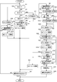
- driving support mode switching control configuration by each step will be described with reference to FIG. 5 showing the flow of the driving support mode switching control process executed by the mode transition controller 47 provided in the ADAS control unit 4. This process starts when the operation of the driving support control is started, and ends when the operation of the driving support control is released.
- step S1 following the determination that the operation release condition of the driving support control is not satisfied at the start or S6, it is determined whether or not the driving support mode is the "steering wheel support release mode M4". If YES (“handle support release mode M4”), the process proceeds to step S32, and if NO (other than “handle support release mode M4”), the process proceeds to step S2.
- step S2 following the determination in S1 that the mode is other than the "steering wheel support release mode M4", it is determined whether or not the driving support mode is the "hands-off mode M1". If YES (“hands-off mode M1”), the process proceeds to step S7, and if NO (other than “hands-off mode M1”), the process proceeds to step S3.
- step S3 following the determination in S2 that the mode is other than the "hands-off mode M1", it is determined whether or not the driving support mode is the "hands-on mode M2". If YES (“hands-on mode M2”), the process proceeds to step S4, and if NO (other than “hands-on mode M2”), the process proceeds to step S6.
- step S4 following the determination of "hands-on mode M2" in S3, it is determined whether or not the hands-off condition for switching from "hands-on mode M2" to "hands-off mode M1" is satisfied. If YES (hands-off condition is satisfied), the process proceeds to step S5, and if NO (hands-off condition is not satisfied), the process proceeds to step S6.
- step S5 following the determination that the hands-off condition is satisfied in S4, the mode transitions from "hands-on mode M2" to "hands-off mode M1", and the process proceeds to step S6.
- step S6 the mode transition to the "hands-off mode M1" in S5, the mode transition to the "hands-on mode M2" in S34, the mode transition to the "handle support release mode M4" in S21, or Following the determination of NO in S3, S7, and S32, it is determined whether or not the operation release condition of the driving support control is satisfied. If YES (the cancellation condition is satisfied), the process proceeds to the end, and if NO (the cancellation condition is not satisfied), the process returns to step S1.
- step S7 following the determination in S2 that the vehicle is in the "hands-off mode M1", it is determined whether or not a lane disappearance region S in which a continuous lane cannot be recognized from the own lane is detected on the extension of the traveling route of the own vehicle. to decide. If YES (the lane disappearance area S is detected), the process proceeds to step S8, and if NO (the lane disappearance area S is not detected), the process proceeds to step S6.
- step S8 following the determination that the lane disappearance region S in S7 is detected, it is assumed that the own vehicle travels along the travel route toward the lane disappearance region S, and whether or not the lane change is required. To judge. If YES (no lane change required), the process proceeds to step S9, and if NO (no lane change required), the process proceeds to step S10.
- step S9 following the determination that the lane change is not required in S8, the position of the first distance X1 from the lane disappearance start point Ps1 is set to the first position P1, and the process proceeds to step S11.
- step S10 following the determination that the lane change is required in S8, the lane change start point Pe1 is set to the first position P1 and the process proceeds to step S11. That is, the setting of the first position P1 is different depending on whether or not it is necessary to change lanes.
- step S11 following the setting of the first position P1 in S9 or S10, it is determined whether or not there is a curved road C having a turning radius of a predetermined value or less in front of the lane disappearance region S. If YES (there is no curve road C), the process proceeds to step S12, and if NO (there is a curve road C), the process proceeds to step S13.
- step S12 following the determination that there is no curved road C in S11, the position of the second distance X2 shorter than the first distance X1 from the lane disappearance start point Ps1 is set to the second position P2, and the process proceeds to step S14.
- step S13 following the determination that there is a curved road C in S11, the position of the second distance X2 shorter than the first distance X1 from the curved road start point Pc1 is set to the second position P2, and the process proceeds to step S14. That is, the setting of the second distance X2 is different depending on the presence or absence of the curved path C.
- step S14 following the setting of the second position P2 in S12 or S13, it is determined whether or not the own vehicle has reached the first position P1. If YES (the first position P1 has been reached), the process proceeds to step S15, and if NO (the first position P1 has not been reached), the determination in step S14 is repeated.
- step S15 following the determination that the first position P1 in S14 has been reached, a mode transition from "hands-off mode M1" to "hands-on mode M2" is requested, and the process proceeds to step S16.
- step S16 following the mode transition to the "hands-on mode M2" in S15, it is determined whether or not the driver has grasped the steering wheel 23 within a predetermined time from the mode transition request to the "hands-on mode M2". If YES (holding the steering wheel within the predetermined time), the process proceeds to step S17, and if NO (not holding the steering wheel within the predetermined time), the process proceeds to step S23.
- step S17 following the determination that the steering wheel has been gripped within the predetermined time in S16, it is determined whether or not the own vehicle has reached the second position P2. If YES (the second position P2 has been reached), the process proceeds to step S18, and if NO (the second position P2 has not been reached), the determination in step S17 is repeated.
- step S18 following the determination that the second position P2 in S17 has been reached, the mode transition from the "hands-on mode M2" to the "handle operation mode M3" is requested, and the process proceeds to step S19.
- step S19 following the mode transition to the "steering wheel operation mode M3" in S18 or the determination that the predetermined time has not elapsed in M3 in S22, whether or not the own vehicle has reached the lane disappearance start point Ps1. To judge. If YES (the lane disappearance start point Ps1 has been reached), the process proceeds to step S21, and if NO (the lane disappearance start point Ps1 has not been reached), the process proceeds to step S20.
- step S20 following the determination that the lane disappearance start point Ps1 in S19 has not been reached, it is determined whether or not the driver holding the steering wheel 23 has operated the steering wheel. If YES (the steering wheel is operated), the process proceeds to step S21, and if NO (the steering wheel is not operated), the process proceeds to step S22.
- step S21 following the determination that the lane disappearance start point Ps1 in S19 has been reached or the steering wheel has been operated in S20, the mode is changed from "steering wheel operation mode M3" to "steering wheel support release mode M4". The transition is performed, and the process proceeds to step S6.
- step S22 following the determination that the steering wheel is not operated in S20, it is determined in the "handle operation mode M3" whether or not the predetermined time has elapsed. If YES (predetermined time has elapsed in M3), the process proceeds to step S23, and if NO (predetermined time has not elapsed in M3), the process returns to step S19.
- step S23 following the determination that the steering wheel is not held within the predetermined time in S16 or the determination that the predetermined time has elapsed in M3 in S22, the vehicle is decelerated / stopped and the process proceeds to step S24. .. At this time, "Decelerate” is displayed on the displays 61 and 62, and the vehicle is decelerated and stopped.
- step S24 following the deceleration / stop of the own vehicle in S23, the driving support control (vertical control + horizontal control) is released, and the process proceeds to the end.
- step S32 following the determination in the "steering wheel support release mode M4" in S1, it is determined whether or not the own vehicle has passed the lane extinction region S and reached the lane extinction end point Ps2. If YES (the lane disappearance end point Ps2 has been reached), the process proceeds to step S33, and if NO (the lane disappearance end point Ps2 has not been reached), the process proceeds to step S6.
- step S33 following the determination that the lane disappearance end point Ps2 in S32 has been reached, it is determined whether or not lane recognition has been resumed by the front recognition camera. If YES (lane recognition has been restarted), the process proceeds to step S34, and if NO (lane recognition has not been restarted), the process proceeds to step S6.
- step S34 following the determination that the lane recognition in S33 has been resumed, the mode transitions from the "steering wheel support release mode M4" to the "hands-on mode M2", and the process proceeds to step S6.
- a driving support vehicle that has a vehicle speed / inter-vehicle distance control function and a lane-keeping function as a driving support function to support the driver's driving operation, and which runs in a single lane while keeping the lane on the condition that the driver touches the steering wheel is known. ing.
- This driving support vehicle is intended to be driven mainly by the driver, as long as the driver touches the steering wheel. Therefore, there is a demand for further raising the driving support level, delegating the driving subject from the driver to the system, and enabling automatic driving in which the driver releases his / her hand from the steering wheel.
- Patent Document 1 Japanese Unexamined Patent Publication No. 9-86223
- voice information such as "Cancel automatic steering, please prepare” is emitted from the speaker.
- the automatic steering is canceled and the steering is entrusted to the driver.
- the automatic steering may be canceled when the driver is left in the state of being released from the steering wheel. That is, when switching from automatic driving to driver driving, when the main body of the steering wheel operation is transferred from the system to the driver, there is a problem that the transfer to the driver does not go well because the transfer is performed at once only by notifying.
- the present inventors can obtain information from map data or the like that there is an area in which steering wheel support is canceled because a continuous lane from the own lane cannot be recognized on the extension of the traveling route of the own vehicle. It can be obtained. Then, by grasping the area where the steering wheel support is released in advance, a marginal traveling section until the vehicle reaches the steering wheel support release point is generated, and it is possible to confirm the driver's gripping of the steering wheel in this marginal traveling section. I focused on the point.
- the driving support method of the present disclosure is such that during lane-keeping driving in which "hands-off mode M1" is selected, lanes that cannot recognize continuous lanes from the own lane on the extension of the driving route of the own vehicle disappear.
- the area S is detected.
- the mode transition position (first position P1, second position P2) is set between the own vehicle position and the lane disappearance start point Ps1. ..
- the mode transition from the "hands-off mode M1" to the steering wheel gripping mode (“hands-on mode M2", "steering wheel operation mode M3" is requested.
- the head-up display 61 and the meter display 62 have a steering wheel icon display unit, a limited vehicle speed display unit, a set vehicle speed display unit, a message display unit, a lane / own vehicle display unit, and the like. Then, while the "hands-off mode M1" is selected, as shown in the display D1 of FIG. 6, the handle icon display unit is displayed in blue, for example, and the icon of only the handle is displayed.
- the handle icon display unit is displayed in green, for example, and the handle is held by hand. Display the icon. Then, "Hold the steering wheel. It's the tollhouse in the future.” Is displayed and announced on the message display.
- the handle icon display unit is displayed in red, for example, and the handle is held by hand. Display the icon. Then, "Please operate. It is a tollhouse in the future.” Is displayed and announced on the message display.
- the handle icon display unit is displayed in white, for example, and the handle and hand icons are displayed. Turn off the display.
- the driver may be notified of the transition of the driving support mode by changing the display of the head-up display 61 and the meter display 62. it can.
- S7 it is determined whether or not a lane disappearance region S in which a continuous lane cannot be recognized from the own lane is detected on the extension of the traveling route of the own vehicle. While the lane disappearance region S is not detected, the flow of proceeding from S1 ⁇ S2 ⁇ S7 ⁇ S6 is repeated. After that, when it is determined that the lane disappearance region S is detected in S7, the process proceeds from S7 to S8, and in S8, when it is assumed that the own vehicle travels toward the lane disappearance region S along the travel route. , It is judged whether or not the lane change is necessary.
- next S11 it is determined whether or not there is a curved road C having a turning radius of a predetermined value or less in front of the lane disappearance region S. If there is no curved road C, the process proceeds from S11 to S12, and if there is a curved road C. Proceeds from S11 to S13. In S12, the position of the second distance X2 shorter than the first distance X1 from the lane disappearance start point Ps1 is set to the second position P2. In step S13, the position of the second distance X2 shorter than the first distance X1 from the curve road start point Pc1 is set to the second position P2.
- next S14 it is determined whether or not the own vehicle has reached the first position P1, and when it reaches the first position P1, the vehicle proceeds to S15.
- S15 a mode transition from "hands-off mode M1" to "hands-on mode M2" is required.
- S16 it is determined whether or not the steering wheel is gripped within the predetermined time, and if the steering wheel is gripped within the predetermined time, the process proceeds to S17, and if the steering wheel is not gripped within the predetermined time, the process proceeds to S23.
- next S17 it is determined whether or not the own vehicle has reached the second position P2, and when it reaches the second position P2, the process proceeds to S18.
- S18 a mode transition from the "hands-on mode M2" to the "handle operation mode M3" is required.
- next S19 it is determined whether or not the own vehicle has reached the lane disappearance start point Ps1.
- the process proceeds to S21, and in S21, the mode is changed from the "steering wheel operation mode M3" to the "steering wheel support release mode M4", and the process proceeds to S6.
- next S20 it is determined whether or not the steering wheel has been operated, and if it is determined that the steering wheel has been operated, the process proceeds to S21.
- the mode is changed from the "handle operation mode M3" to the "handle support release mode M4". Proceed to S6.
- S33 it is determined by the front recognition camera whether or not lane recognition has been resumed. After that, when the lane recognition is restarted, the process proceeds from S33 to S34, and in S34, the mode is changed from the "steering wheel support release mode M4" to the "hands-on mode M2", and the process proceeds to S6. After that, the process proceeds from S1 ⁇ S2 ⁇ S3 ⁇ S4, and when it is determined that the hands-off condition is satisfied in S4, the process proceeds from S4 to S5, and in S5, from “hands-on mode M2” to “hands-off mode M1”. The mode is changed and the mode is returned to the "hands-off mode M1".
- the mode transition control process that proceeds from "hands-off mode M1"->"hands-on mode M2"->"handle operation mode M3"->"handle support release mode M4" is performed at the first position P1 and the second position P2. It can be divided into the following (a) to (d) with different settings. (a) When it is not necessary to change lanes and there is no curved road C, the first position P1 is set to the position of the first distance X1 from the lane disappearance start point Ps1, and the second position P2 is set to the lane disappearance start point Ps1. The position is set to the second distance X2, which is shorter than the first distance X1.
- the first position P1 is set to the position of the first distance X1 from the curved road start point Pc1 and the second position P2 is set to the curved road start point Pc1. It is set at the position of the second distance X2, which is shorter than the first distance X1.
- the first position P1 is set as the lane change start point Pe1 and the second position P2 is the position of the second distance X2 from the lane disappearance start point Ps1.
- the first position P1 is set as the lane change start point Pe1 and the second position P2 is the position of the second distance X2 from the curved road start point Pc1. Set to.
- driving support mode switching control action when heading to the lane disappearance region S in the lane-keeping driving by the "hands-off mode M1" will be described separately for four different driving scenes corresponding to the above (a) to (d). ..
- the first position P1 is the first distance X1 from the lane disappearance start point Ps1 (depending on the speed limit of the road, for example, 800 m. Degree) is set to the position.
- the second position P2 is set at a position of a second distance X2 (for example, about 150 m, which varies depending on the speed limit of the road), which is shorter than the first distance X1 from the lane disappearance start point Ps1.
- the tollhouse While driving in lane keep to the tollhouse on the main line in "hands-off mode M1", the tollhouse (lane disappearance) that cannot recognize the continuous lane from the own lane on the extension of the driving route of the own vehicle based on the high-precision map data. It is assumed that the area S) is detected. In this case, when the tollhouse is detected, the information of the lane disappearance start point Ps1 and the lane disappearance end point Ps2 is acquired. Then, the first position P1 and the second position P2 starting from the lane disappearance start point Ps1 are set between the own vehicle position and the lane disappearance start point Ps1.
- the first position P1 is set to a position of a first distance X1 from the curved road start point Pc1 as shown in FIG.
- the second position P2 is set at a position of a second distance X2 shorter than the first distance X1 from the curve road start point Pc1.
- the first position P1 is set to the position of the lane change start point Pe1 as shown in FIG.
- the second position P2 is set at a position of a second distance X2 from the lane disappearance start point Ps1.
- the branch road Y when the branch road Y is detected, the information of the lane change start point Pe1 and the lane change completion point Pe2 is acquired by the route traveling support function.
- the first position P1 is set to the position of the lane change start point Pe1 as shown in FIG.
- the second position P2 is set at a position of a second distance X2 from the curve road start point Pc1.
- the branch road Y, the curve road C and the own lane are added to the extension of the driving route of the own vehicle. It is assumed that a tollhouse (lane disappearance area S) that cannot recognize continuous lanes is detected.
- the branch road Y when the branch road Y is detected, the information of the lane change start point Pe1 and the lane change completion point Pe2 is acquired by the route traveling support function.
- the curved road C When the curved road C is detected, the information of the curved road start point Pc1 and the curved road end point Pc2 is acquired.
- the driving support method and the driving support device of the first embodiment have the effects listed below.
- a driving support method using a mode transition controller 47 that has a vehicle speed / inter-vehicle distance control function and a lane keeping function as driving support functions to support the driving operation of the driver and transitions to the driving support mode.
- “Hands-off mode M1” that allows the driver to release the handle 23
- "Handle grip modes M2 and M3” that require the driver to hold the handle 23 by hand
- "Hands-off mode M2, M3” that cancels the lane keeping function.
- a lane disappearance area S that has "handle support release mode M4" and cannot recognize continuous lanes from the own lane on the extension of the driving route of the own vehicle during lane keeping driving in which "hands-off mode M1" is selected.
- the driving support level is gradually lowered to more reliably transfer the system to the driver. It is possible to provide a driving support method.
- the mode transition position (first position P1, second position P2)
- the lane disappearance region S is detected on the extension of the traveling route of the own vehicle during lane keeping driving in which "hands-off mode M1" is selected.
- the vehicle is calculated back and set so that the vehicle can be decelerated / stopped when the lane disappearance start point Ps1 is reached (S9, S10, S12, S13 in FIG. 5). Therefore, the mode transition positions (first position P1 and second position P2) can be set to appropriate positions at which the own vehicle can be decelerated / stopped when the lane disappearance start point Ps1 is reached.
- the steering wheel gripping mode has a "hands-on mode M2" that requires the driver to put his hand on the steering wheel and a “steering wheel operation mode M3" that prompts the driver to operate the steering wheel, and has a lane disappearance start point Ps1.
- the first position P1 and the second position P2 are set between the own vehicle position and the lane disappearance start point Ps1, and when the own vehicle reaches the first position P1, "hands-off mode M1" Requests a mode transition from “hands-on mode M2" to "hands-on mode M2", and when the vehicle reaches the second position P2, requests a mode transition from "hands-on mode M2" to "steering wheel operation mode M3", and the steering wheel 23 by the driver.
- the mode transitions from the "steering wheel operation mode M3" to the "steering wheel support release mode M4" (S16 ⁇ S17 in FIG. 5). ⁇ S18 ⁇ S19 ⁇ S21). Therefore, in the lane-keeping driving scene in the "hands-off mode M1", from the system to the driver by the time the vehicle reaches the lane disappearance start point Ps1 while it is confirmed that the driver has grasped the steering wheel 23. Can be secured without any discomfort.
- the touch sensor 92 monitors whether or not the driver has touched the handle 23, and "hands-on mode M2" to "hands-on mode M2".
- the torque sensor 93 monitors whether or not the driver has operated the handle (S16, S20 in FIG. 5). Therefore, when the steering wheel gripping mode has the "hands-on mode M2" and the "handle operation mode M3", the behavioral mode of the driver with respect to the steering wheel 23 can be divided into each of the two modes and monitored with high accuracy.
- the first position P1 is set to the position of the first distance X1 from the lane disappearance start point Ps1.
- the second position P2 is set to the position of the second distance X2 shorter than the first distance X1 from the lane disappearance start point Ps1 (S9 and S12 in FIG. 5). Therefore, when the lane-keeping lane in the "hands-off mode M1" is a road that does not require a lane change of the own vehicle, the first position P1 and the second position P2 are set with the lane disappearance start point Ps1 as the starting point. Can be done.
- the steering control is performed when the driver reaches the lane change start point Pe1 required to drive along the driving route and the driver's intention to change lanes is confirmed.
- the first position P1 is set as the lane change start point Pe1.
- the second position P2 is set to a position separated from the lane disappearance start point Ps1 by a predetermined distance (second distance X2) (S10 in FIG. 5).
- the first position P1 can be set to the lane change start point Pe1 and the second position P2 can be set.
- the lane disappearance start point Ps1 can be set as a starting point.
- the lane is used on the condition that the driving route is generated based on the setting of the destination by the driver (in conjunction with the navigation system 7), and the route driving support function is used. You can make changes.
- the target lateral acceleration of the curve-linked deceleration in the "handle operation mode M3" is set to "hands-on mode M2" and "hands". It is set lower than the target lateral acceleration value of the curve-linked deceleration in the "off mode M1" and the "handle support release mode M4". Therefore, the driver can be given a sense of security by lowering the vehicle speed when handing over the steering wheel operation to the driver on the curved road C as compared with other modes. In addition, it is possible to secure a long time for the driver to adjust the operation feeling after delivery.
- the lane-keeping driving section in which the "hands-off mode M1" is selected can be selected. It can be secured for a long time. That is, it is possible to return from the "steering wheel support release mode M4" to the "hands-on mode M2" on condition that the lane recognition is resumed, and further, if the hands-off condition is satisfied while the "hands-on mode M2" is selected, the "hands-off” is achieved. You can return to "mode M1".
- a driving support device having a vehicle speed / inter-vehicle distance control function and a lane keeping function as a driving support function for assisting a driver's driving operation, and a mode transition controller 47 for transitioning a driving support mode, as a driving support mode.
- “Hands-off mode M1” that allows the driver to release the handle
- “Handle grip modes M2 and M3” that require the driver to hold the handle 23 by hand
- “Hands-off mode M2, M3” that cancels the lane keeping function.
- the mode transition controller 47 has a "handle support release mode M4" and a lane continuous from the own lane on the extension of the driving route of the own vehicle during lane keeping driving in which the "hands-off mode M1" is selected.
- the lane disappearance area detection unit 471 that detects the unrecognizable lane disappearance area S and the information of the lane disappearance start point Ps1 when the lane disappearance area S is detected are acquired between the own vehicle position and the lane disappearance start point Ps1.
- the position setting unit 472 that sets the mode transition position (first position P1, second position P2), and when the own vehicle reaches the mode transition position, the "hands-off mode M1" is changed to the "handle gripping modes M2, M3".
- the vehicle When the mode transition request unit (hands-on mode transition request unit 473, handle operation mode transition request unit 474) that requests the mode transition and the driver grasping the handle 23 are confirmed, the vehicle reaches the lane disappearance start point Ps1. It has a handle support release mode transition unit 475 that makes a mode transition from the "handle gripping modes M2 and M3" to the "handle support release mode M4" (FIG. 4). For this reason, in the driving scene in the mode in which the driving support level is raised, when the steering wheel support release is grasped in advance, the driving support level is gradually lowered to more reliably transfer the system to the driver. Equipment can be provided.
- Example 1 as the mode transition controller 47, an example of mode transition from “hands-off mode M1” ⁇ “hands-on mode M2” ⁇ “handle operation mode M3” ⁇ “handle support release mode M4” is shown.
- the mode transition controller may have at least one mode in which it can be confirmed that the driver has the steering wheel between the "hands-off mode” and the "steering wheel support release mode".
- a mode transition may be made from “hands-off mode”-> "handle gripping mode”-> "handle support release mode”.
- it may be an example of mode transition from "hands-off mode”-> "hands-on mode”-> "handle gripping mode”-> "handle operation mode”-> "handle support release mode”.
- Example 1 the driving support method and the driving support device of the present disclosure are applied to a driving support vehicle equipped with the advanced driving support system ADAS that supports the driving operation of the driver.
- the driving support method and the driving support device of the present disclosure perform driving / braking / steering angle operation support control according to the target driving locus, and automatically drive the vehicle in automatic driving (AD). It can be applied to vehicles.
Abstract
In a travel scene in a mode in which the driving assistance level is raised, the present invention lowers the driving assistance level in stages if it is ascertained in advance that steering wheel assistance cancellation is to be cancelled and thereby better ensures that the driver takes over control from the system. The present invention has a vehicle speed/vehicle-to-vehicle distance control function and a lane keeping function as driving assistance functions for assisting driving operations by a driver and is provided with a mode transition controller (47). While in lane keeping travel in which a hands-off mode M1 is selected, the present invention detects a lane disappearance region (S) in which it is not possible to recognize a lane that continues from the host vehicle lane on an extension of the travel route of the host vehicle. When the lane disappearance region (S) is detected, information for a lane disappearance commencement point (Ps1) is acquired, and a first position (P1) and a second position (P2) are set between the host vehicle position and the lane disappearance commencement point (Ps1). The first position (P1), the second position (P2), and the lane disappearance commencement point (Ps1) are treated as mode transition positions, and transitions are made from the hands-off mode M1 to a hands-on mode M2 to a steering wheel operation mode M3 to a steering wheel assistance cancellation mode M4.
Description
本開示は、運転支援方法及び運転支援装置に関する。
This disclosure relates to a driving support method and a driving support device.
従来、自動運転からドライバー運転への切換えに際し、スピーカから「自動操舵を解除します、準備して下さい」との音声情報を発し、自動操舵を解除してステアリングをドライバーに委ねる。自動操舵の解除を行うと、次に走行偏差が所定の許容範囲以下であるか否かを判定する。そして、この判定がYesであった場合にのみ、「自動アクセルと自動ブレーキを解除します、準備して下さい」との音声情報を発し、自動アクセルと自動ブレーキとを解除してアクセルとブレーキとをドライバーに委ねる。しかる後、表示装置の画面上での「自動運転中」の表示を中止する、自動運転装置が知られている(例えば、特許文献1参照)。
Conventionally, when switching from automatic driving to driver driving, voice information such as "Cancel automatic steering, please prepare" is emitted from the speaker, and automatic steering is canceled and steering is entrusted to the driver. When the automatic steering is released, it is next determined whether or not the traveling deviation is within a predetermined allowable range. Then, only when this judgment is Yes, the voice information "The automatic accelerator and the automatic brake are released, please prepare" is issued, and the automatic accelerator and the automatic brake are released, and the accelerator and the brake are released. To the driver. After that, there is known an automatic driving device that stops displaying "in automatic driving" on the screen of the display device (see, for example, Patent Document 1).
従来装置は、自動運転からドライバー運転への切換えの際、まず、自動操舵を解除し、対象区間通過後に自動アクセルと自動ブレーキを解除している。しかし、ドライバーの運転操作を支援する運転支援制御において、ドライバーによる運転操作の支援レベルを上げる運転支援高度化に伴い、システムからドライバーへの委譲をより確実に行うことが求められる、という課題があった。
In the conventional device, when switching from automatic driving to driver driving, the automatic steering is first released, and the automatic accelerator and automatic brake are released after passing the target section. However, in driving support control that supports the driver's driving operation, there is a problem that it is required to more reliably transfer from the system to the driver with the advancement of driving support that raises the level of support for the driving operation by the driver. It was.
本開示は、上記課題に着目してなされたもので、運転支援レベルを上げたモードでの走行シーンにおいて、ハンドル支援解除が事前に把握されると運転支援レベルを段階的に下げることで、システムからドライバーへの委譲をより確実に行うことを目的とする。
This disclosure focuses on the above issues, and in a driving scene in a mode in which the driving support level is raised, the driving support level is gradually lowered when the steering wheel support release is grasped in advance. The purpose is to make the transfer from the driver to the driver more reliably.
上記目的を達成するため、本開示は、ドライバーの運転操作を支援する運転支援機能として車速・車間制御機能とレーンキープ機能を有し、運転支援モードを遷移するモード遷移コントローラによる運転支援方法である。運転支援モードとして、ドライバーがハンドルから手を離すことを許可するハンズオフモードと、ドライバーがハンドルを手で握ることを条件とするハンドル把持モードと、レーンキープ機能を解除するハンドル支援解除モードと、を有する。ハンズオフモードが選択されているレーンキープ走行中、自車の走行ルートの延長上に自車線から連続する車線を認識できない車線消滅領域を検出する。車線消滅領域が検出されると車線消滅開始点の情報を取得し、自車位置と車線消滅開始点との間にモード遷移位置を設定する。自車がモード遷移位置に到達すると、ハンズオフモードからハンドル把持モードへのモード遷移を要求する。ドライバーによるハンドルの把持が確認された場合、自車が車線消滅開始点に到達するまでに、ハンドル把持モードからハンドル支援解除モードへモード遷移する。
In order to achieve the above object, the present disclosure is a driving support method using a mode transition controller that has a vehicle speed / inter-vehicle distance control function and a lane keeping function as driving support functions for assisting a driver's driving operation and transitions to a driving support mode. .. The driving support modes include a hands-off mode that allows the driver to take his hand off the steering wheel, a steering wheel grip mode that requires the driver to hold the steering wheel with his hand, and a steering wheel support release mode that cancels the lane keeping function. Has. During lane-keeping driving in which the hands-off mode is selected, a lane disappearance area where continuous lanes cannot be recognized from the own lane is detected on the extension of the driving route of the own vehicle. When the lane disappearance area is detected, the information on the lane disappearance start point is acquired, and the mode transition position is set between the own vehicle position and the lane disappearance start point. When the vehicle reaches the mode transition position, the mode transition from the hands-off mode to the steering wheel gripping mode is requested. When it is confirmed that the driver grips the steering wheel, the mode transitions from the steering wheel gripping mode to the steering wheel support release mode by the time the vehicle reaches the lane disappearance start point.
上記課題解決手段を採用したため、運転支援レベルを上げたモードでの走行シーンにおいて、ハンドル支援解除が事前に把握されると運転支援レベルを段階的に下げることで、システムからドライバーへの委譲をより確実に行うことができる。
Since the above-mentioned problem-solving means has been adopted, in the driving scene in the mode in which the driving support level is raised, when the steering wheel support release is grasped in advance, the driving support level is gradually lowered to further transfer the system to the driver. You can do it with certainty.
以下、本開示による運転支援方法及び運転支援装置を実施するための形態を、図面に示す実施例1に基づいて説明する。
Hereinafter, a mode for implementing the driving support method and the driving support device according to the present disclosure will be described based on the first embodiment shown in the drawings.
実施例1における運転支援方法及び運転支援装置は、ドライバーの運転操作を支援する先進運転支援システムADAS(「Advanced Driver Assistance Systems」の略称)を搭載した運転支援車両に適用したものである。以下、実施例1の構成を、「全体システム構成」、「モード遷移コントローラの制御ブロック構成」、「運転支援モード切り替え制御処理構成」に分けて説明する。
The driving support method and the driving support device in the first embodiment are applied to a driving support vehicle equipped with an advanced driving support system ADAS (abbreviation of "Advanced Driver Assistance Systems") that supports the driving operation of the driver. Hereinafter, the configuration of the first embodiment will be described separately as "overall system configuration", "mode transition controller control block configuration", and "driving support mode switching control processing configuration".
[全体システム構成]
図1は、実施例1の運転支援方法及び運転支援装置が適用された先進運転支援システムを示す。図2は、運転支援車両のドライバーシート位置からフロントウィンドウを視たときの車室内構成を示す。図3は、運転支援車両のハンドルに設けられたドライバーによる操作スイッチを示す。以下、図1~図3に基づいて全体システム構成を説明する。 [Overall system configuration]
FIG. 1 shows an advanced driving support system to which the driving support method and the driving support device of the first embodiment are applied. FIG. 2 shows the vehicle interior configuration when the front window is viewed from the driver's seat position of the driving support vehicle. FIG. 3 shows an operation switch by a driver provided on the steering wheel of a driving support vehicle. Hereinafter, the overall system configuration will be described with reference to FIGS. 1 to 3.
先進運転支援システムADASは、車速・車間制御機能、レーンキープ機能、ルート走行支援機能を持つシステムである。そして、図1に示すように、車載センサ1と、地図データ記憶部2と、外部データ通信器3と、ADAS制御ユニット4と、アクチュエータ5と、HMIデバイス6と、ナビゲーションシステム7と、操作スイッチ8と、制御情報センサ類9と、を備えている。なお、「HMI」は「Human Machine Interface」の略称である。
The advanced driver assistance system ADAS is a system that has a vehicle speed / inter-vehicle distance control function, a lane keeping function, and a route driving support function. Then, as shown in FIG. 1, an in-vehicle sensor 1, a map data storage unit 2, an external data communication device 3, an ADAS control unit 4, an actuator 5, an HMI device 6, a navigation system 7, and an operation switch are used. 8 and control information sensors 9 are provided. "HMI" is an abbreviation for "Human Machine Interface".
車載センサ1は、カメラ11と、レーダー12と、GPS13と、車載データ通信器14と、を有する。車載センサ1により取得したセンサ情報は、ADAS制御ユニット4へ出力される。
The in-vehicle sensor 1 includes a camera 11, a radar 12, a GPS 13, and an in-vehicle data communication device 14. The sensor information acquired by the in-vehicle sensor 1 is output to the ADAS control unit 4.
カメラ11は、自車線や隣接車線や自車周囲車両や自車周囲歩行者等の自車の周囲情報を画像データにより取得する機能を実現する自車周囲認識センサである。カメラ11としては、前方認識カメラ、後方認識カメラ、右方認識カメラ、左方認識カメラ等を組み合わせ、アラウンドビューモニタ機能を持たせた構成としている。このカメラ11では、自車走行路上物体・車線・自車走行路外物体(道路構造物、先行車、後続車、対向車、周囲車両、歩行者、自転車、二輪車)・自車走行路(道路白線、道路境界、停止線、横断歩道)・道路標識(制限速度)等が検知される。
The camera 11 is a vehicle surrounding recognition sensor that realizes a function of acquiring information on the surroundings of the vehicle such as the vehicle's lane, adjacent lanes, vehicles around the vehicle, and pedestrians around the vehicle from image data. The camera 11 is configured to have an around view monitor function by combining a front recognition camera, a rear recognition camera, a right recognition camera, a left recognition camera, and the like. In this camera 11, the vehicle's on-road object, lane, own vehicle's off-road object (road structure, preceding vehicle, following vehicle, oncoming vehicle, surrounding vehicle, pedestrian, bicycle, two-wheeled vehicle), own vehicle's driving road (road) White lines, road boundaries, stop lines, pedestrian crossings), road signs (speed limit), etc. are detected.
レーダー12は、自車周囲の物体の存在を検知する機能と共に、自車周囲の物体までの距離を検知する機能を実現する測距センサである。ここで、「レーダー12」とは、電波を用いたレーダーと、光を用いたライダーと、超音波を用いたソナーと、を含む総称をいう。このレーダー12では、自車走行路上物体・自車走行路外物体(道路構造物、先行車、後続車、対向車、周囲車両、歩行者、自転車、二輪車)等の位置が検知されると共に、各物体までの距離が検知される。
The radar 12 is a distance measuring sensor that realizes a function of detecting the presence of an object around the vehicle and a function of detecting the distance to an object around the vehicle. Here, "radar 12" is a general term including a radar using radio waves, a rider using light, and a sonar using ultrasonic waves. The radar 12 detects the positions of objects on the vehicle's road and objects outside the vehicle's road (road structures, preceding vehicles, following vehicles, oncoming vehicles, surrounding vehicles, pedestrians, bicycles, motorcycles), and at the same time. The distance to each object is detected.
GPS13は、GNSSアンテナ13aを有し、衛星通信を利用することで停車中/走行中の自車位置(緯度・経度)を検知する自車位置センサである。なお、「GNSS」は「Global Navigation Satellite System:全地球航法衛星システム」の略称であり、「GPS」は「Global Positioning System:グローバル・ポジショニング・システム」の略称である。
GPS 13 is a vehicle position sensor that has a GNSS antenna 13a and detects the vehicle position (latitude / longitude) while the vehicle is stopped / running by using satellite communication. In addition, "GNSS" is an abbreviation for "Global Navigation Satellite System", and "GPS" is an abbreviation for "Global Positioning System".
車載データ通信器14は、外部データ通信器3との間で送受信アンテナ3a,14aを介して無線通信を行うことで、車載センサ1や地図データで取得することができない情報を外部から取得する外部データセンサである。ここで、「外部データ通信器3」が、例えば、自車の周辺を走行する他車に搭載されたデータ通信器の場合、自車と他車の間で車車間通信を行い、他車が保有する様々な情報のうち、自車で必要な情報をリクエストにより取得することができる。また、「外部データ通信器3」が、例えば、インフラ設備に設けられたデータ通信器の場合、自車とインフラ設備の間でインフラ通信を行い、自車で必要な情報をリクエストにより取得することができる。例えば、地図データ記憶部2に保存されている地図データでは不足する情報や地図データから変更された情報がある場合、不足/変更情報を補うことができる。また、自車の走行経路上での渋滞情報や走行規制情報等の交通情報も取得できる。
The in-vehicle data communication device 14 performs wireless communication with the external data communication device 3 via the transmission / reception antennas 3a and 14a to acquire information that cannot be acquired by the in-vehicle sensor 1 or map data from the outside. It is a data sensor. Here, in the case where the "external data communication device 3" is, for example, a data communication device mounted on another vehicle traveling around the own vehicle, vehicle-to-vehicle communication is performed between the own vehicle and the other vehicle, and the other vehicle performs inter-vehicle communication. Of the various information that we have, we can obtain the information that is necessary for our vehicle upon request. Further, when the "external data communication device 3" is, for example, a data communication device installed in the infrastructure equipment, the infrastructure communication is performed between the own vehicle and the infrastructure equipment, and the necessary information in the own vehicle is acquired by request. Can be done. For example, if there is insufficient information in the map data stored in the map data storage unit 2 or information changed from the map data, the missing / changed information can be supplemented. In addition, traffic information such as traffic congestion information and driving regulation information on the traveling route of the own vehicle can be acquired.
地図データ記憶部2は、緯度経度と地図情報が対応づけられた、いわゆる電子地図データが格納された車載メモリにより構成される。地図データ記憶部2に格納される地図データは、高精度地図データを有さない地域を除いて、基本的に車線を認識することができるレベルの精度を持つ高精度地図データとする。そして、GPS13にて検知される自車位置がADAS制御ユニット4にて認識されると、自車位置を中心とする所定範囲の高精度地図データがADAS制御ユニット4やナビゲーションシステム7へと送られる。
The map data storage unit 2 is composed of an in-vehicle memory that stores so-called electronic map data in which latitude / longitude and map information are associated with each other. The map data stored in the map data storage unit 2 is basically high-precision map data having a level of accuracy that allows lane recognition, except for areas that do not have high-precision map data. Then, when the own vehicle position detected by the GPS 13 is recognized by the ADAS control unit 4, high-precision map data in a predetermined range centered on the own vehicle position is sent to the ADAS control unit 4 and the navigation system 7. ..
ここで、「高精度地図データ」には、各地点に対応づけられた道路情報を有し、道路情報は、ノードと、ノード間を接続するリンクにより定義される。道路情報は、道路の位置/領域により道路を特定する情報と、道路ごとの道路種別、道路毎の車線幅、道路の形状情報とを含む。道路情報は、各道路リンクの識別情報毎に、交差点の位置、交差点の進入方向、交差点の種別その他の交差点に関する情報を対応づけて記憶されている。また、道路情報は、各道路リンクの識別情報ごとに、道路種別、車線幅、道路形状、直進の可否、進行の優先関係、追い越しの可否(隣接レーンへの進入の可否)、制限速度、標識、その他の道路に関する情報を対応づけて記憶されている。
Here, the "high-precision map data" has road information associated with each point, and the road information is defined by a node and a link connecting the nodes. The road information includes information for identifying a road according to the position / area of the road, road type for each road, lane width for each road, and road shape information. The road information is stored in association with the location of the intersection, the approach direction of the intersection, the type of the intersection, and other information related to the intersection for each identification information of each road link. In addition, the road information includes the road type, lane width, road shape, whether or not to go straight, the priority relationship of progress, whether or not to pass (whether or not to enter the adjacent lane), speed limit, and sign for each road link identification information. , Other road information is associated and stored.
ADAS制御ユニット4は、運転支援制御を統合するユニットであり、車速・車間制御機能を分担するコントローラとして、アクセル/ブレーキ支援コントローラ41と、走行駆動源コントローラ42と、ブレーキコントローラ43と、を有する。そして、レーンキープ機能を分担するコントローラとして、ハンドル支援コントローラ44と、ステアリングコントローラ45と、を有する。さらに、先進運転支援システムADASの場合、ドライバーとシステムとのコミュニケーションをとる機能を分担するコントローラとして、HMIコントローラ46を有する。加えて、先進運転支援システムADASの場合、ドライバーのハンドル手離しによる運転支援モードまで運転支援レベルを上げたことに伴い、運転支援モードの切り替え制御を行うモード遷移コントローラ47を有する。
The ADAS control unit 4 is a unit that integrates driving support control, and has an accelerator / brake support controller 41, a traveling drive source controller 42, and a brake controller 43 as controllers that share the vehicle speed / inter-vehicle distance control function. A steering wheel support controller 44 and a steering controller 45 are included as controllers that share the lane keeping function. Further, in the case of the advanced driver assistance system ADAS, the HMI controller 46 is provided as a controller that shares the function of communicating between the driver and the system. In addition, the advanced driver assistance system ADAS has a mode transition controller 47 that controls switching of the driving assistance mode as the driving assistance level is raised to the driving assistance mode by releasing the steering wheel of the driver.
アクセル/ブレーキ支援コントローラ41は、ドライバーによるアクセル操作とブレーキ操作を支援する下記の制御を行う。
(a) 先行車を検出しているときは、ドライバーがセットした車速を上限とし、車速に応じた車間距離を保つように車間制御を行う。
(b) 先行車を検出していない場合は、設定車速で定速走行する。
(c) 先行車が停止したとき、先行車に続いて自車も停止する。
(d) 先行車が発進したとき、リジューム・アクセラレートスイッチ82(図3参照)を押すか、アクセルペダルを踏むと停止状態を解除し、再び追従走行を開始する。
(e) 車速・車間制御機能により自車が停止しているとき、システム解除操作を行うと、電動パーキングブレーキアクチュエータ53への指令により電動パーキングブレーキを作動させる。 The accelerator /brake support controller 41 performs the following controls to support the accelerator operation and the brake operation by the driver.
(a) When the preceding vehicle is detected, the vehicle speed set by the driver is set as the upper limit, and the vehicle-to-vehicle distance control is performed so as to maintain the inter-vehicle distance according to the vehicle speed.
(b) If the preceding vehicle is not detected, the vehicle will run at a constant speed at the set vehicle speed.
(c) When the preceding vehicle stops, the own vehicle also stops following the preceding vehicle.
(d) When the preceding vehicle starts, pressing the resume / accelerate switch 82 (see FIG. 3) or depressing the accelerator pedal releases the stopped state and starts following driving again.
(e) When the own vehicle is stopped by the vehicle speed / inter-vehicle distance control function and the system is released, the electric parking brake is activated by a command to the electricparking brake actuator 53.
(a) 先行車を検出しているときは、ドライバーがセットした車速を上限とし、車速に応じた車間距離を保つように車間制御を行う。
(b) 先行車を検出していない場合は、設定車速で定速走行する。
(c) 先行車が停止したとき、先行車に続いて自車も停止する。
(d) 先行車が発進したとき、リジューム・アクセラレートスイッチ82(図3参照)を押すか、アクセルペダルを踏むと停止状態を解除し、再び追従走行を開始する。
(e) 車速・車間制御機能により自車が停止しているとき、システム解除操作を行うと、電動パーキングブレーキアクチュエータ53への指令により電動パーキングブレーキを作動させる。 The accelerator /
(a) When the preceding vehicle is detected, the vehicle speed set by the driver is set as the upper limit, and the vehicle-to-vehicle distance control is performed so as to maintain the inter-vehicle distance according to the vehicle speed.
(b) If the preceding vehicle is not detected, the vehicle will run at a constant speed at the set vehicle speed.
(c) When the preceding vehicle stops, the own vehicle also stops following the preceding vehicle.
(d) When the preceding vehicle starts, pressing the resume / accelerate switch 82 (see FIG. 3) or depressing the accelerator pedal releases the stopped state and starts following driving again.
(e) When the own vehicle is stopped by the vehicle speed / inter-vehicle distance control function and the system is released, the electric parking brake is activated by a command to the electric
一般に“クルーズコントロール”と呼ばれる上記(a)~(e)による車速・車間制御以外にアクセル/ブレーキ支援コントローラ41は下記の制御を行う。
(f) 車速・車間制御機能により自車が走行しているとき、ドライバーのスイッチ操作による設定車速の変更(上下)を許容する。
(g) 制限速度標識検知機能により、新しい制限速度を検出した場合、制限速度アシスト表示が点灯するとともに、ディスプレイ上に“設定車速が変更されました”が表示され、検出した制限速度を反映して設定車速にする。但し、ドライバーのスイッチ操作により、設定車速を制限速度よりも高い速度に設定した後、制限速度が上がっても設定車速を超えない場合は制限速度を設定車速に反映しない(制限速度アシスト)。
(h) 車速・車間制御機能により自車が走行しているとき、一時的に加速したいときはアクセルペダルを踏むと加速を許容する。アクセルペダルを操作して加速しているときは、ブレーキ制御、接近警報、カーブ警報を行わない。アクセルペダルを離すと、それまでの車速・車間制御に復帰する。
(i) 車速・車間制御機能により自車が走行しているとき、一時的に減速したいときはブレーキペダルを踏むと減速を許容する。なお、減速前の設定車速で再びセットしたいときは、リジューム・アクセラレートスイッチ82(図3参照)を押す。
(j) カーブ路を走行するときは、地図情報に基づいて前方のカーブの大きさに応じた車速で走行できるように車速制御を行う(カーブ連動減速)。このカーブ連動減速機能は、高精度地図データ又はナビゲーションシステムから取得した曲率情報を用い、横加速度が所定の値以下になるように目標速度の上限を定める機能である。つまり、カーブ連動減速機能は、横加速度が所定の値以下になるようにカーブ路の曲率と位置から逆算してカーブ路より手前から減速を開始し、各道路における減速を完了した状態で走行する。このとき、「ハンドル操作モード」でのカーブ連動減速の目標加速度を、「ハンズオンモード」、「ハンズオフモード」、「ハンドル線解除モード」でのカーブ連動減速の目標加速度の値よりも低くしている。 In addition to the vehicle speed / inter-vehicle distance control according to the above (a) to (e), which is generally called "cruise control", the accelerator /brake support controller 41 performs the following control.
(f) When the own vehicle is running by the vehicle speed / inter-vehicle distance control function, the set vehicle speed can be changed (up and down) by the driver's switch operation.
(g) When a new speed limit is detected by the speed limit sign detection function, the speed limit assist display lights up and "Set vehicle speed has been changed" is displayed on the display to reflect the detected speed limit. Set the vehicle speed. However, after setting the set vehicle speed to a speed higher than the speed limit by operating the switch of the driver, if the speed limit does not exceed the set vehicle speed even if the speed limit increases, the speed limit is not reflected in the set vehicle speed (speed limit assist).
(h) When the vehicle is running by the vehicle speed / inter-vehicle distance control function and you want to accelerate temporarily, you can allow acceleration by depressing the accelerator pedal. When accelerating by operating the accelerator pedal, brake control, approach warning, and curve warning are not performed. When the accelerator pedal is released, the vehicle speed and inter-vehicle distance control up to that point are restored.
(i) When the vehicle is running by the vehicle speed / inter-vehicle distance control function and you want to decelerate temporarily, deceleration is allowed by depressing the brake pedal. If you want to set the vehicle speed again at the set vehicle speed before deceleration, press the resume / accelerate switch 82 (see FIG. 3).
(j) When driving on a curved road, the vehicle speed is controlled based on the map information so that the vehicle can travel at a vehicle speed according to the size of the curve in front (curve-linked deceleration). This curve-linked deceleration function is a function that sets an upper limit of the target speed so that the lateral acceleration becomes a predetermined value or less by using the high-precision map data or the curvature information acquired from the navigation system. That is, the curve-linked deceleration function calculates back from the curvature and position of the curved road so that the lateral acceleration is equal to or less than a predetermined value, starts deceleration from before the curved road, and travels in a state where deceleration on each road is completed. .. At this time, the target acceleration of the curve-linked deceleration in the "steering wheel operation mode" is set lower than the target acceleration of the curve-linked deceleration in the "hands-on mode", "hands-off mode", and "handle line release mode". There is.
(f) 車速・車間制御機能により自車が走行しているとき、ドライバーのスイッチ操作による設定車速の変更(上下)を許容する。
(g) 制限速度標識検知機能により、新しい制限速度を検出した場合、制限速度アシスト表示が点灯するとともに、ディスプレイ上に“設定車速が変更されました”が表示され、検出した制限速度を反映して設定車速にする。但し、ドライバーのスイッチ操作により、設定車速を制限速度よりも高い速度に設定した後、制限速度が上がっても設定車速を超えない場合は制限速度を設定車速に反映しない(制限速度アシスト)。
(h) 車速・車間制御機能により自車が走行しているとき、一時的に加速したいときはアクセルペダルを踏むと加速を許容する。アクセルペダルを操作して加速しているときは、ブレーキ制御、接近警報、カーブ警報を行わない。アクセルペダルを離すと、それまでの車速・車間制御に復帰する。
(i) 車速・車間制御機能により自車が走行しているとき、一時的に減速したいときはブレーキペダルを踏むと減速を許容する。なお、減速前の設定車速で再びセットしたいときは、リジューム・アクセラレートスイッチ82(図3参照)を押す。
(j) カーブ路を走行するときは、地図情報に基づいて前方のカーブの大きさに応じた車速で走行できるように車速制御を行う(カーブ連動減速)。このカーブ連動減速機能は、高精度地図データ又はナビゲーションシステムから取得した曲率情報を用い、横加速度が所定の値以下になるように目標速度の上限を定める機能である。つまり、カーブ連動減速機能は、横加速度が所定の値以下になるようにカーブ路の曲率と位置から逆算してカーブ路より手前から減速を開始し、各道路における減速を完了した状態で走行する。このとき、「ハンドル操作モード」でのカーブ連動減速の目標加速度を、「ハンズオンモード」、「ハンズオフモード」、「ハンドル線解除モード」でのカーブ連動減速の目標加速度の値よりも低くしている。 In addition to the vehicle speed / inter-vehicle distance control according to the above (a) to (e), which is generally called "cruise control", the accelerator /
(f) When the own vehicle is running by the vehicle speed / inter-vehicle distance control function, the set vehicle speed can be changed (up and down) by the driver's switch operation.
(g) When a new speed limit is detected by the speed limit sign detection function, the speed limit assist display lights up and "Set vehicle speed has been changed" is displayed on the display to reflect the detected speed limit. Set the vehicle speed. However, after setting the set vehicle speed to a speed higher than the speed limit by operating the switch of the driver, if the speed limit does not exceed the set vehicle speed even if the speed limit increases, the speed limit is not reflected in the set vehicle speed (speed limit assist).
(h) When the vehicle is running by the vehicle speed / inter-vehicle distance control function and you want to accelerate temporarily, you can allow acceleration by depressing the accelerator pedal. When accelerating by operating the accelerator pedal, brake control, approach warning, and curve warning are not performed. When the accelerator pedal is released, the vehicle speed and inter-vehicle distance control up to that point are restored.
(i) When the vehicle is running by the vehicle speed / inter-vehicle distance control function and you want to decelerate temporarily, deceleration is allowed by depressing the brake pedal. If you want to set the vehicle speed again at the set vehicle speed before deceleration, press the resume / accelerate switch 82 (see FIG. 3).
(j) When driving on a curved road, the vehicle speed is controlled based on the map information so that the vehicle can travel at a vehicle speed according to the size of the curve in front (curve-linked deceleration). This curve-linked deceleration function is a function that sets an upper limit of the target speed so that the lateral acceleration becomes a predetermined value or less by using the high-precision map data or the curvature information acquired from the navigation system. That is, the curve-linked deceleration function calculates back from the curvature and position of the curved road so that the lateral acceleration is equal to or less than a predetermined value, starts deceleration from before the curved road, and travels in a state where deceleration on each road is completed. .. At this time, the target acceleration of the curve-linked deceleration in the "steering wheel operation mode" is set lower than the target acceleration of the curve-linked deceleration in the "hands-on mode", "hands-off mode", and "handle line release mode". There is.
走行駆動源コントローラ42は、アクセル/ブレーキ支援コントローラ41によって目標車速が生成されると、自車の実車速が目標車速になるように駆動指令値を演算し、駆動アクチュエータ51へ出力する縦制御を行う。
When the target vehicle speed is generated by the accelerator / brake support controller 41, the traveling drive source controller 42 calculates a drive command value so that the actual vehicle speed of the own vehicle becomes the target vehicle speed, and performs vertical control to output to the drive actuator 51. Do.
ブレーキコントローラ43は、アクセル/ブレーキ支援コントローラ41によって目標制動減速度が生成されると、自車の実制動減速度が目標制動減速度になるように制動指令値を演算し、制動アクチュエータ52へ出力する縦制御を行う。
When the target braking deceleration is generated by the accelerator / brake support controller 41, the brake controller 43 calculates a braking command value so that the actual braking deceleration of the own vehicle becomes the target braking deceleration, and outputs the braking command value to the braking actuator 52. Perform vertical control.
ハンドル支援コントローラ44は、前方認識カメラによる車線両側のレーンマーカーの検出に基づいて、車線の中央部を自車が走行するようにステアリング制御(横制御)し、ドライバーのステアリング操作を支援するレーンキープ機能を発揮する。このハンドル支援コントローラ44には、レーンキープ機能以外に、ナビゲーションシステム7との連動により、ドライバーが目的地を設定している場合、予め生成された走行ルートに沿ってレーンキープ走行していることを条件とするルート走行支援機能を有する。ルート走行支援機能は、走行ルートに沿って走行するために必要な車線変更開始点に到達すると、表示によりドライバーに車線変更を行うか否かを確認し、ドライバーがスイッチ操作した場合、ステアリング制御により車線変更を支援する。
The steering wheel support controller 44 controls the steering (lateral control) so that the vehicle travels in the center of the lane based on the detection of the lane markers on both sides of the lane by the front recognition camera, and keeps the lane to assist the driver's steering operation. Demonstrate function. In addition to the lane keeping function, the steering wheel support controller 44 is linked with the navigation system 7, and when the driver sets the destination, the steering wheel assist controller 44 is informed that the lane keeping traveling is performed along the traveling route generated in advance. It has a route driving support function as a condition. When the route driving support function reaches the lane change start point required to drive along the driving route, the display confirms with the driver whether or not to change lanes, and when the driver operates the switch, the steering control is used. Support lane changes.
ステアリングコントローラ45は、ハンドル支援コントローラ44によって車線の中央部を自車が走行する目標舵角が生成されると、自車の実舵角が目標舵角になるように舵角指令値を演算し、舵角アクチュエータ54へ出力する横制御を行う。
When the steering wheel support controller 44 generates a target steering angle for the vehicle to travel in the center of the lane, the steering controller 45 calculates a steering angle command value so that the actual steering angle of the vehicle becomes the target steering angle. , The lateral control to output to the steering angle actuator 54 is performed.
HMIコントローラ46は、車速・車間制御機能とレーンキープ機能の作動状態や作動状態変化を視覚により認識できるように、ヘッドアップディスプレイ61とメータディスプレイ62への表示指令を生成する。例えば、「ハンズオフモード」、「ハンズオンモード」、「ハンドル操作モード」、「ハンドル支援解除モード」を表示するとき、モード別色分け表示やアイコン表示やメッセージ表示を活用し、ドライバーが一見するだけで作動状態を理解できるように表示する。また、ドライバーに対して聴覚に訴えるアナウンスを必要とするとき、スピーカ63への音声信号を生成し、ドライバーに対して聴覚に訴える警報を必要とするとき、警報器64の作動/停止指令を生成する。
The HMI controller 46 generates display commands to the head-up display 61 and the meter display 62 so that the operating state and the operating state change of the vehicle speed / inter-vehicle distance control function and the lane keeping function can be visually recognized. For example, when displaying "hands-off mode", "hands-on mode", "steering wheel operation mode", and "steering wheel support release mode", the driver can use the color-coded display by mode, icon display, and message display at a glance. Display the operating status so that you can understand it. Further, when an announcement appealing to the driver is required, an audio signal to the speaker 63 is generated, and when an alarm appealing to the driver is required, an activation / stop command of the alarm device 64 is generated. To do.
ここで、HMIデバイス6に有するヘッドアップディスプレイ61は、図2に示すように、フロントウィンドウ21の下部位置に設定され、灯光器でウィンドシールドにシステム状態等を表示する。メータディスプレイ62は、インストルメントパネル22の計器表示部に設定され、システム作動状態や周辺車両の状態等を表示する。スピーカ63及び警報器64は、インストルメントパネル22のパネル内側の所定位置に設定される。
Here, the head-up display 61 included in the HMI device 6 is set at a lower position of the front window 21 as shown in FIG. 2, and a light device displays the system status and the like on the windshield. The meter display 62 is set on the instrument display unit of the instrument panel 22 and displays a system operating state, a state of surrounding vehicles, and the like. The speaker 63 and the alarm 64 are set at predetermined positions inside the instrument panel 22.
モード遷移コントローラ47は、ハンズオフモードが選択されているレーンキープ走行中、自車の走行ルートの延長上に自車線から連続する車線を認識できない車線消滅領域を検出する。車線消滅領域が検出されると車線消滅開始点の情報を取得し、自車位置と車線消滅開始点との間に第1位置と第2位置を設定する。自車が第1位置に到達すると、ハンズオフモードからハンズオンモードへのモード遷移を要求する。自車が第2位置に到達すると、ハンズオンモードからハンドル操作モードへのモード遷移を要求する。ドライバーによるハンドルの把持が確認された場合、自車が車線消滅開始点に到達するまでに、ハンドル操作モードからハンドル支援解除モードへモード遷移する。
The mode transition controller 47 detects a lane disappearing region in which a continuous lane cannot be recognized from the own lane on the extension of the traveling route of the own vehicle during lane keeping driving in which the hands-off mode is selected. When the lane disappearance area is detected, the information on the lane disappearance start point is acquired, and the first position and the second position are set between the own vehicle position and the lane disappearance start point. When the own vehicle reaches the first position, it requests a mode transition from the hands-off mode to the hands-on mode. When the vehicle reaches the second position, it requests a mode transition from the hands-on mode to the steering wheel operation mode. When it is confirmed that the driver holds the steering wheel, the mode transitions from the steering wheel operation mode to the steering wheel support release mode by the time the vehicle reaches the lane disappearance start point.
ここで、「ハンズオフモード」とは、ドライバーがハンドル23から手を離すことを許可する運転支援モードをいう。「ハンズオンモード」とは、ドライバーがハンドル23に手を添えることを条件とする運転支援モードをいう。「ハンドル操作モード」とは、ハンドル操作をドライバーに促す運転支援モードをいう。「ハンドル支援解除モード」とは、レーンキープ機能を解除する運転支援モードをいう。即ち、「ハンズオフモード」と「ハンズオンモード」と「ハンドル操作モード」は、ドライバーがハンドル23から手を離すことを許可するモードか、手を添えることを要求するモードか、手で操作することを要求するモードかという点でのみ相違するモードであり、運転支援制御を変えるモードではない。一方、「ハンドル支援解除モード」は、ハンドル支援コントローラ44によるレーンキープ機能を解除し、アクセル/ブレーキ支援コントローラ41による車速・車間制御機能は残すモードである。つまり、「ハンドル支援解除モード」は、ハンドル操作をシステムからドライバーへ委譲するモードである。
Here, the "hands-off mode" refers to a driving support mode that allows the driver to take his / her hand off the steering wheel 23. The "hands-on mode" refers to a driving support mode that requires the driver to touch the steering wheel 23. The "steering wheel operation mode" refers to a driving support mode that prompts the driver to operate the steering wheel. The "steering wheel support release mode" refers to a driving support mode that cancels the lane keeping function. That is, the "hands-off mode", "hands-on mode", and "handle operation mode" are a mode that allows the driver to take his / her hand off the steering wheel 23, a mode that requires the driver to add a hand, or a mode that requires the driver to operate by hand. It is a mode that differs only in that it is a mode that requires, and is not a mode that changes driving support control. On the other hand, the "steering wheel support release mode" is a mode in which the lane keeping function by the steering wheel support controller 44 is canceled and the vehicle speed / inter-vehicle distance control function by the accelerator / brake support controller 41 is left. That is, the "steering wheel support release mode" is a mode in which the steering wheel operation is delegated from the system to the driver.
ナビゲーションシステム7は、地図データ記憶部2に格納している地図データと衛星通信を利用したGPS13を組み合わせ、目的地を設定すると、現在の自車位置から目的地までの走行ルートを生成し、目的地まで自車を道案内するシステムである。そして、走行ルートが生成されると、走行ルートと自車アイコンとともに道路地図画面をナビディスプレイ71に表示する。ナビディスプレイ71は、図2に示すように、インストルメントパネル22の中央上部位置に配置され、ドライバーによるタッチ操作等により目的地を設定する機能を有する。
When the navigation system 7 combines the map data stored in the map data storage unit 2 with the GPS 13 using satellite communication and sets the destination, the navigation system 7 generates a traveling route from the current vehicle position to the destination and aims. It is a system that guides your vehicle to the ground. Then, when the traveling route is generated, the road map screen is displayed on the navigation display 71 together with the traveling route and the own vehicle icon. As shown in FIG. 2, the navigation display 71 is arranged at the upper center position of the instrument panel 22 and has a function of setting a destination by a touch operation or the like by a driver.
操作スイッチ8は、図2に示すように、ハンドル23のうち、ステアリングホイールとステアリングシャフトを繋ぐステアリングハブであって、ドライバーがステアリングホイールを持ったままで指により操作可能な位置に設定される。操作スイッチ8としては、メインスイッチ81とリジューム・アクセラレートスイッチ82とセット・コーストスイッチ83とキャンセルスイッチ84と車間調整スイッチ85と車線変更支援スイッチ86とを有する。メインスイッチ81は、システムの電源オン・オフスイッチである。リジューム・アクセラレートスイッチ82は、作動解除後に解除前の設定車速で作動を再開する機能、設定車速を上げる機能、先行車に追従して停止した後に再発進する機能を有する。セット・コーストスイッチ83は、走行時の車速で作動を開始する機能、設定車速を下げる機能を有する。キャンセルスイッチ84は、作動を解除するスイッチである。車間調整スイッチ85は、設定車間を切り替えるスイッチである。車線変更支援スイッチ86は、システムが車線変更の開始をドライバーに確認したとき、車線変更の開始を指示するスイッチである。
As shown in FIG. 2, the operation switch 8 is a steering hub that connects the steering wheel and the steering shaft in the steering wheel 23, and is set at a position that can be operated by a finger while the driver holds the steering wheel. The operation switch 8 includes a main switch 81, a resume acceleration switch 82, a set coast switch 83, a cancel switch 84, an inter-vehicle distance adjustment switch 85, and a lane change support switch 86. The main switch 81 is a system power on / off switch. The resume / accelerate switch 82 has a function of restarting the operation at the set vehicle speed before the release after the operation is released, a function of increasing the set vehicle speed, and a function of restarting after stopping following the preceding vehicle. The set coast switch 83 has a function of starting operation at the vehicle speed during traveling and a function of lowering the set vehicle speed. The cancel switch 84 is a switch that releases the operation. The inter-vehicle distance adjustment switch 85 is a switch for switching between set inter-vehicle distances. The lane change support switch 86 is a switch that instructs the driver to start the lane change when the system confirms the start of the lane change to the driver.
ここで、メインスイッチ81を押した後、設定したい車速まで加速又は減速し、セット・コーストスイッチ83を押すと、走行している道路の制限速度が設定車速になり、ADAS制御ユニット4による運転支援制御の作動を開始する。なお、走行している道路の制限速度を検出していない場合、又は、制限速度アシストをオフにしている場合は、セット・コーストスイッチ83を押したときの速度が設定車速になり、ADAS制御ユニット4による運転支援制御の作動を開始する。
Here, after pressing the main switch 81, the vehicle accelerates or decelerates to the vehicle speed to be set, and when the set coast switch 83 is pressed, the speed limit of the road on which the vehicle is traveling becomes the set vehicle speed, and the driving support by the ADAS control unit 4 Start the control operation. If the speed limit of the road on which the vehicle is traveling is not detected, or if the speed limit assist is turned off, the speed when the set coast switch 83 is pressed becomes the set vehicle speed, and the ADAS control unit The operation of the driving support control according to 4 is started.
ADAS制御ユニット4による運転支援制御の作動を解除するときは、キャンセルスイッチ84を押す、又は、メインスイッチ81を押す、又は、ブレーキペダルを踏む(但し、車速・車間制御機能により、自車が停止しているときを除く。)の何れかの操作を行う。
To cancel the operation of the driving support control by the ADAS control unit 4, press the cancel switch 84, press the main switch 81, or depress the brake pedal (however, the vehicle stops due to the vehicle speed / inter-vehicle distance control function). Perform any of the operations in)).
制御情報センサ類9は、ADAS制御ユニット4による運転支援制御を実行する際に必要な情報を取得する。制御情報センサ類9としては、図2に示すように、ドライバーモニタカメラ91、タッチセンサ92、着座センサ94、シートベルトバックルスイッチ95を有する。その他、図1に示すように、トルクセンサ93、車速センサ96、アクセル開度センサ97を有する。
The control information sensors 9 acquire information necessary for executing the driving support control by the ADAS control unit 4. As shown in FIG. 2, the control information sensors 9 include a driver monitor camera 91, a touch sensor 92, a seating sensor 94, and a seatbelt buckle switch 95. In addition, as shown in FIG. 1, it has a torque sensor 93, a vehicle speed sensor 96, and an accelerator opening sensor 97.
ドライバーモニタカメラ91は、カメラレンズをドライバーに向けて設定され、ドライバーの前方注視(顔の向き、開眼/閉眼)を監視する。タッチセンサ92(静電容量センサ)は、ハンドル23のうちドライバーが手を添えるステアリングホイールに設定され、ドライバーがハンドル23に手を添えていることを検出する。トルクセンサ93は、ステアリング機構の操舵力伝達部に設置され、ドライバーが操舵トルクを加えてハンドル操作していることを検出する。着座センサ94(重量センサ)は、ドライバーシートのシートクッション24に設定され、ドライバーが着座していることを検出する。シートベルトバックルスイッチ95は、シートベルトがロックされていることを検出する。車速センサ96は、自車の実車速を検出する。アクセル開度センサ97は、ドライバーによりアクセル操作が行われたときにアクセル操作量を検出する。
The driver monitor camera 91 is set with the camera lens facing the driver, and monitors the driver's forward gaze (face orientation, eye open / closed). The touch sensor 92 (capacitance sensor) is set on the steering wheel of the steering wheel 23 to which the driver touches, and detects that the driver is touching the steering wheel 23. The torque sensor 93 is installed in the steering force transmission unit of the steering mechanism, and detects that the driver applies steering torque to operate the steering wheel. The seating sensor 94 (weight sensor) is set on the seat cushion 24 of the driver's seat and detects that the driver is seated. The seatbelt buckle switch 95 detects that the seatbelt is locked. The vehicle speed sensor 96 detects the actual vehicle speed of the own vehicle. The accelerator opening sensor 97 detects the accelerator operation amount when the driver operates the accelerator.
[モード遷移コントローラの制御ブロック構成]
以下、ADAS制御ユニット4に有するモード遷移コントローラ47を示す図4に基づいて、モード遷移コントローラ47の制御ブロック構成を説明する。 [Control block configuration of mode transition controller]
Hereinafter, the control block configuration of themode transition controller 47 will be described with reference to FIG. 4 showing the mode transition controller 47 included in the ADAS control unit 4.
以下、ADAS制御ユニット4に有するモード遷移コントローラ47を示す図4に基づいて、モード遷移コントローラ47の制御ブロック構成を説明する。 [Control block configuration of mode transition controller]
Hereinafter, the control block configuration of the
モード遷移コントローラ47は、図4に示すように、車線消滅領域検出部471と、位置設定部472と、ハンズオンモード遷移要求部473と、ハンドル操作モード遷移要求部474と、ハンドル支援解除モード遷移部475と、を有する。さらに、ハンズオンモード遷移要求部476と、ハンズオフモード遷移部477と、を有する。
As shown in FIG. 4, the mode transition controller 47 includes a lane disappearance area detection unit 471, a position setting unit 472, a hands-on mode transition request unit 473, a steering wheel operation mode transition request unit 474, and a steering wheel support release mode transition unit. It has 475 and. Further, it has a hands-on mode transition request unit 476 and a hands-off mode transition unit 477.
車線消滅領域検出部471は、「ハンズオフモードM1」が選択されているレーンキープ走行中、自車の走行ルートの延長上に自車線から連続する車線を認識できない車線消滅領域を検出する。ここで、「車線消滅領域」とは、下記の箇所等をいう。
(a) 出口:車線の属性や中心線等の情報による地図データがない箇所。具体的には、高速道路の出口やサービスエリアやパーキングエリア等をいう。
(b) 料金所:地図データはあり、車線がないという情報がある箇所。
(c) 無車線区間(無車線増加、無車線減少):地図データはあり、車線がないという情報がある箇所。
(d) 合流:地図データあり、合流により自車線が消滅するという情報がある箇所。
(e) 車線減少:地図データあり、車線減少により自車線が消滅するという情報がある箇所。 The lane disappearancearea detection unit 471 detects a lane disappearance area in which a lane continuous from the own lane cannot be recognized on the extension of the travel route of the own vehicle during lane keeping driving in which the "hands-off mode M1" is selected. Here, the "lane disappearance area" refers to the following locations and the like.
(a) Exit: A place where there is no map data based on information such as lane attributes and center lines. Specifically, it refers to an exit of an expressway, a service area, a parking area, and the like.
(b) Tollhouse: A place where there is map data and there is information that there is no lane.
(c) Laneless section (increased lanes, decreased lanes): Locations with map data and information that there are no lanes.
(d) Confluence: A place where there is map data and there is information that the own lane will disappear due to the confluence.
(e) Lane reduction: There is map data, and there is information that your lane will disappear due to lane reduction.
(a) 出口:車線の属性や中心線等の情報による地図データがない箇所。具体的には、高速道路の出口やサービスエリアやパーキングエリア等をいう。
(b) 料金所:地図データはあり、車線がないという情報がある箇所。
(c) 無車線区間(無車線増加、無車線減少):地図データはあり、車線がないという情報がある箇所。
(d) 合流:地図データあり、合流により自車線が消滅するという情報がある箇所。
(e) 車線減少:地図データあり、車線減少により自車線が消滅するという情報がある箇所。 The lane disappearance
(a) Exit: A place where there is no map data based on information such as lane attributes and center lines. Specifically, it refers to an exit of an expressway, a service area, a parking area, and the like.
(b) Tollhouse: A place where there is map data and there is information that there is no lane.
(c) Laneless section (increased lanes, decreased lanes): Locations with map data and information that there are no lanes.
(d) Confluence: A place where there is map data and there is information that the own lane will disappear due to the confluence.
(e) Lane reduction: There is map data, and there is information that your lane will disappear due to lane reduction.
位置設定部472は、車線消滅領域が検出されると車線消滅開始点の情報を取得し、自車位置と車線消滅開始点との間に第1位置(自車に近い位置)と第2位置(自車から遠い位置)を設定する。
When the lane disappearance area is detected, the position setting unit 472 acquires information on the lane disappearance start point, and the first position (position close to the own vehicle) and the second position between the own vehicle position and the lane disappearance start point. Set (position far from your vehicle).
ハンズオンモード遷移要求部473は、自車が第1位置に到達すると、「ハンズオフモードM1」から「ハンズオンモードM2」へのモード遷移を要求する。ここで、第1位置の設定は、自車の車線変更を要しない道路であるのか、車線変更を要する道路であるのかにより異ならせている。
When the own vehicle reaches the first position, the hands-on mode transition request unit 473 requests a mode transition from the "hands-off mode M1" to the "hands-on mode M2". Here, the setting of the first position is different depending on whether the road does not require the lane change of the own vehicle or the road requires the lane change.
なお、「ハンズオンモードM2」へのモード遷移の要求は、ディスプレイ61,62への色分け・アイコン・メッセージの表示を変更すると共に“ハンドルを持って下さい。”とアナウンスすることで行う。そして、「ハンズオンモードM2」へのモード遷移の確認は、タッチセンサ92からのセンサ信号を監視することで行う。さらに、「ハンズオンモードM2」へのモード遷移要求にもかかわらず、所定時間以内にドライバーがハンドルを持ったことが検出できないと、自車を減速・停止させた後、運転支援制御の作動(縦制御+横制御)そのものを解除する。
The mode transition request to "hands-on mode M2" is made by changing the color coding, icon, and message display on the displays 61 and 62 and announcing "Hold the steering wheel." Then, the mode transition to the "hands-on mode M2" is confirmed by monitoring the sensor signal from the touch sensor 92. Further, if it cannot be detected that the driver holds the steering wheel within a predetermined time despite the mode transition request to the "hands-on mode M2", the driver decelerates and stops the vehicle, and then the driving support control is activated (vertical). (Control + horizontal control) itself is released.
ハンドル操作モード遷移要求部474は、自車が第2位置に到達すると、「ハンズオンモードM2」から「ハンドル操作モードM3」へのモード遷移を要求する。ここで、第2位置の設定は、車線消滅領域の手前に旋回半径が所定以下のカーブ路が存在しないのか存在するのかにより位置決め距離の起点を異ならせている。
When the vehicle reaches the second position, the steering wheel operation mode transition request unit 474 requests a mode transition from the "hands-on mode M2" to the "steering wheel operation mode M3". Here, in the setting of the second position, the starting point of the positioning distance is different depending on whether or not there is a curved road having a turning radius of a predetermined value or less in front of the lane disappearance region.
なお、「ハンドル操作モードM3」へのモード遷移の要求は、ディスプレイ61,62への色分け・アイコン・メッセージの表示を変更すると共に“操作して下さい。”とアナウンスすることで行う。そして、「ハンドル操作モードM3」へのモード遷移の確認は、トルクセンサ93からのセンサ信号を監視することで行う。さらに、「ハンドル操作モードM3」へのモード遷移要求にもかかわらず、所定時間待ってもドライバーのハンドル操作が検出できないと、自車を減速・停止させた後、運転支援制御の作動(縦制御+横制御)そのものを解除する。
The mode transition request to the "handle operation mode M3" is made by changing the color coding, icon, and message display on the displays 61 and 62 and announcing "Please operate." Then, the mode transition to the "handle operation mode M3" is confirmed by monitoring the sensor signal from the torque sensor 93. Furthermore, if the driver's steering wheel operation cannot be detected even after waiting for a predetermined time despite the mode transition request to the "steering wheel operation mode M3", the driver's vehicle is decelerated / stopped, and then the driving support control is activated (vertical control). + Lateral control) itself is released.
ハンドル支援解除モード遷移部475は、自車が車線消滅開始点に到達すると、「ハンドル操作モードM3」から「ハンドル支援解除モードM4」へモード遷移する。なお、「ハンドル支援解除モードM4」へモード遷移すると、ディスプレイ61,62への色分け・アイコン・メッセージの表示を変更する。「ハンドル支援解除モードM4」へのモード遷移条件は、第1位置や第2位置の設定にかかわらず、車線消滅開始点への到達という同じ条件で与えている。
When the vehicle reaches the lane disappearance start point, the steering wheel support release mode transition unit 475 makes a mode transition from the "steering wheel operation mode M3" to the "steering wheel support release mode M4". When the mode transitions to the "handle support release mode M4", the color coding, icon, and message display on the displays 61 and 62 are changed. The mode transition condition to the "steering wheel support release mode M4" is given under the same condition of reaching the lane disappearance start point regardless of the setting of the first position or the second position.
ハンズオンモード遷移要求部476は、「ハンドル支援解除モードM4」が選択されている自車が車線消滅領域を通過して車線消滅終了点に到達し、かつ、車線の認識が再開される。車線の認識再開によりドライバーのハンドル操作を支援する横制御を開始することが可能になったことで、「ハンドル支援解除モードM4」から「ハンズオンモードM2」へモード遷移する。ここで、「ハンズオンモードM2」へのモード遷移は、横制御の開始とともに、ディスプレイ61,62への色分け・アイコン・メッセージの表示を変更することで行われる。なお、「ハンドル支援解除モードM4」が選択されているときは、ドライバーはハンドルを持ってステアリング操作を行っている。このため、「ハンドル支援解除モードM4」から「ハンドル操作モードM3」へのモード遷移は省略している。
In the hands-on mode transition request unit 476, the own vehicle for which the "steering wheel support release mode M4" is selected passes through the lane disappearance area, reaches the lane disappearance end point, and recognizes the lane again. By resuming lane recognition, it is possible to start lateral control that assists the driver's steering wheel operation, so that the mode transitions from "steering wheel support release mode M4" to "hands-on mode M2". Here, the mode transition to the "hands-on mode M2" is performed by changing the color coding, the icon, and the message display on the displays 61 and 62 at the same time as the start of the horizontal control. When the "steering wheel support release mode M4" is selected, the driver holds the steering wheel to perform the steering operation. Therefore, the mode transition from the "handle support release mode M4" to the "handle operation mode M3" is omitted.
ハンズオフモード遷移部477は、「ハンズオンモードM2」でのレーンキープ走行中、ハンズオフモード選択条件が成立すると、「ハンズオンモードM2」から「ハンズオフモードM1」へモード遷移する。ここで、手離し可能な「ハンズオフモードM1」へのモード遷移は、ディスプレイ61,62への色分け・アイコン・メッセージの表示を変更することで行われる。なお、「ハンズオフモードM1」を選択するハンズオフ条件は、例えば、“制限速度以下の車速で走行している”、“ドライバーがハンドル23を持っている”、“アクセルペダルが踏まれていない”、等の複数の条件で与えられる。
The hands-off mode transition unit 477 makes a mode transition from "hands-on mode M2" to "hands-off mode M1" when the hands-off mode selection condition is satisfied during lane keeping running in "hands-on mode M2". Here, the mode transition to the "hands-off mode M1" that can be released is performed by changing the color coding, the icon, and the message display on the displays 61 and 62. The hands-off conditions for selecting the "hands-off mode M1" are, for example, "driving at a vehicle speed below the speed limit", "the driver has the steering wheel 23", and "the accelerator pedal is not depressed". , Etc. are given under multiple conditions.
[運転支援モード切り替え制御処理構成]
以下、ADAS制御ユニット4に備えるモード遷移コントローラ47にて実行される運転支援モード切り替え制御処理の流れを示す図5に基づいて、各ステップによる運転支援モード切り替え制御構成を説明する。なお、この処理は、運転支援制御の作動開始によりスタートし、運転支援制御の作動を解除すると終了する。 [Driving support mode switching control processing configuration]
Hereinafter, the driving support mode switching control configuration by each step will be described with reference to FIG. 5 showing the flow of the driving support mode switching control process executed by themode transition controller 47 provided in the ADAS control unit 4. This process starts when the operation of the driving support control is started, and ends when the operation of the driving support control is released.
以下、ADAS制御ユニット4に備えるモード遷移コントローラ47にて実行される運転支援モード切り替え制御処理の流れを示す図5に基づいて、各ステップによる運転支援モード切り替え制御構成を説明する。なお、この処理は、運転支援制御の作動開始によりスタートし、運転支援制御の作動を解除すると終了する。 [Driving support mode switching control processing configuration]
Hereinafter, the driving support mode switching control configuration by each step will be described with reference to FIG. 5 showing the flow of the driving support mode switching control process executed by the
ステップS1では、スタート、或いは、S6での運転支援制御の作動解除条件不成立との判断に続き、運転支援モードが「ハンドル支援解除モードM4」であるか否かを判断する。YES(「ハンドル支援解除モードM4」である)の場合はステップS32へ進み、NO(「ハンドル支援解除モードM4」以外である)の場合はステップS2へ進む。
In step S1, following the determination that the operation release condition of the driving support control is not satisfied at the start or S6, it is determined whether or not the driving support mode is the "steering wheel support release mode M4". If YES (“handle support release mode M4”), the process proceeds to step S32, and if NO (other than “handle support release mode M4”), the process proceeds to step S2.
ステップS2では、S1での「ハンドル支援解除モードM4」以外であるとの判断に続き、運転支援モードが「ハンズオフモードM1」であるか否かを判断する。YES(「ハンズオフモードM1」である)の場合はステップS7へ進み、NO(「ハンズオフモードM1」以外である)の場合はステップS3へ進む。
In step S2, following the determination in S1 that the mode is other than the "steering wheel support release mode M4", it is determined whether or not the driving support mode is the "hands-off mode M1". If YES (“hands-off mode M1”), the process proceeds to step S7, and if NO (other than “hands-off mode M1”), the process proceeds to step S3.
ステップS3では、S2での「ハンズオフモードM1」以外であるとの判断に続き、運転支援モードが「ハンズオンモードM2」であるか否かを判断する。YES(「ハンズオンモードM2」である)の場合はステップS4へ進み、NO(「ハンズオンモードM2」以外である)の場合はステップS6へ進む。
In step S3, following the determination in S2 that the mode is other than the "hands-off mode M1", it is determined whether or not the driving support mode is the "hands-on mode M2". If YES (“hands-on mode M2”), the process proceeds to step S4, and if NO (other than “hands-on mode M2”), the process proceeds to step S6.
ステップS4では、S3での「ハンズオンモードM2」であるとの判断に続き、「ハンズオンモードM2」から「ハンズオフモードM1」へ切り替えるハンズオフ条件が成立しているか否かを判断する。YES(ハンズオフ条件成立)の場合はステップS5へ進み、NO(ハンズオフ条件不成立)の場合はステップS6へ進む。
In step S4, following the determination of "hands-on mode M2" in S3, it is determined whether or not the hands-off condition for switching from "hands-on mode M2" to "hands-off mode M1" is satisfied. If YES (hands-off condition is satisfied), the process proceeds to step S5, and if NO (hands-off condition is not satisfied), the process proceeds to step S6.
ステップS5では、S4でのハンズオフ条件成立との判断に続き、「ハンズオンモードM2」から「ハンズオフモードM1」へモード遷移し、ステップS6へ進む。
In step S5, following the determination that the hands-off condition is satisfied in S4, the mode transitions from "hands-on mode M2" to "hands-off mode M1", and the process proceeds to step S6.
ステップS6では、S5での「ハンズオフモードM1」へのモード遷移、或いは、S34での「ハンズオンモードM2」へのモード遷移、S21での「ハンドル支援解除モードM4」へのモード遷移、或いは、S3、S7、S32でのNOの判断に続き、運転支援制御の作動解除条件成立か否かを判断する。YES(解除条件成立)の場合はエンドへ進み、NO(解除条件不成立)の場合はステップS1へ戻る。
In step S6, the mode transition to the "hands-off mode M1" in S5, the mode transition to the "hands-on mode M2" in S34, the mode transition to the "handle support release mode M4" in S21, or Following the determination of NO in S3, S7, and S32, it is determined whether or not the operation release condition of the driving support control is satisfied. If YES (the cancellation condition is satisfied), the process proceeds to the end, and if NO (the cancellation condition is not satisfied), the process returns to step S1.
ステップS7では、S2での「ハンズオフモードM1」であるとの判断に続き、自車の走行ルートの延長上に自車線から連続する車線を認識できない車線消滅領域Sを検出したか否かを判断する。YES(車線消滅領域Sを検出した)の場合はステップS8へ進み、NO(車線消滅領域Sを検出しない)の場合はステップS6へ進む。
In step S7, following the determination in S2 that the vehicle is in the "hands-off mode M1", it is determined whether or not a lane disappearance region S in which a continuous lane cannot be recognized from the own lane is detected on the extension of the traveling route of the own vehicle. to decide. If YES (the lane disappearance area S is detected), the process proceeds to step S8, and if NO (the lane disappearance area S is not detected), the process proceeds to step S6.
ステップS8では、S7での車線消滅領域Sを検出したとの判断に続き、自車が車線消滅領域Sに向かって走行ルートに沿って走行することを想定したとき、車線変更を要しないか否かを判断する。YES(車線変更を要しない)の場合はステップS9へ進み、NO(車線変更を要する)の場合はステップS10へ進む。
In step S8, following the determination that the lane disappearance region S in S7 is detected, it is assumed that the own vehicle travels along the travel route toward the lane disappearance region S, and whether or not the lane change is required. To judge. If YES (no lane change required), the process proceeds to step S9, and if NO (no lane change required), the process proceeds to step S10.
ステップS9では、S8での車線変更を要しないとの判断に続き、車線消滅開始点Ps1から第1距離X1の位置を第1位置P1に設定し、ステップS11へ進む。
In step S9, following the determination that the lane change is not required in S8, the position of the first distance X1 from the lane disappearance start point Ps1 is set to the first position P1, and the process proceeds to step S11.
ステップS10では、S8での車線変更を要するとの判断に続き、車線変更開始点Pe1を第1位置P1に設定し、ステップS11へ進む。つまり、車線変更を要するか否かにより第1位置P1の設定を異ならせている。
In step S10, following the determination that the lane change is required in S8, the lane change start point Pe1 is set to the first position P1 and the process proceeds to step S11. That is, the setting of the first position P1 is different depending on whether or not it is necessary to change lanes.
ステップS11では、S9又はS10での第1位置P1の設定に続き、車線消滅領域Sの手前に旋回半径が所定値以下のカーブ路Cが無いか否かを判断する。YES(カーブ路Cが無い)の場合はステップS12へ進み、NO(カーブ路Cが有る)の場合はステップS13へ進む。
In step S11, following the setting of the first position P1 in S9 or S10, it is determined whether or not there is a curved road C having a turning radius of a predetermined value or less in front of the lane disappearance region S. If YES (there is no curve road C), the process proceeds to step S12, and if NO (there is a curve road C), the process proceeds to step S13.
ステップS12では、S11でのカーブ路Cが無いとの判断に続き、車線消滅開始点Ps1から第1距離X1より短い第2距離X2の位置を第2位置P2に設定し、ステップS14へ進む。
In step S12, following the determination that there is no curved road C in S11, the position of the second distance X2 shorter than the first distance X1 from the lane disappearance start point Ps1 is set to the second position P2, and the process proceeds to step S14.
ステップS13では、S11でのカーブ路Cが有るとの判断に続き、カーブ路開始点Pc1から第1距離X1より短い第2距離X2の位置を第2位置P2に設定し、ステップS14へ進む。即ち、カーブ路Cの有無により、第2距離X2の設定を異ならせている。
In step S13, following the determination that there is a curved road C in S11, the position of the second distance X2 shorter than the first distance X1 from the curved road start point Pc1 is set to the second position P2, and the process proceeds to step S14. That is, the setting of the second distance X2 is different depending on the presence or absence of the curved path C.
ステップS14では、S12又はS13での第2位置P2の設定に続き、自車が第1位置P1に到達したか否かを判断する。YES(第1位置P1に到達した)の場合はステップS15へ進み、NO(第1位置P1に到達していない)の場合はステップS14の判断を繰り返す。
In step S14, following the setting of the second position P2 in S12 or S13, it is determined whether or not the own vehicle has reached the first position P1. If YES (the first position P1 has been reached), the process proceeds to step S15, and if NO (the first position P1 has not been reached), the determination in step S14 is repeated.
ステップS15では、S14での第1位置P1に到達したとの判断に続き、「ハンズオフモードM1」から「ハンズオンモードM2」へのモード遷移を要求し、ステップS16へ進む。
In step S15, following the determination that the first position P1 in S14 has been reached, a mode transition from "hands-off mode M1" to "hands-on mode M2" is requested, and the process proceeds to step S16.
ステップS16では、S15での「ハンズオンモードM2」へのモード遷移に続き、「ハンズオンモードM2」へのモード遷移要求から所定時間以内にドライバーがハンドル23を握ったか否かを判断する。YES(所定時間以内にハンドルを握った)の場合はステップS17へ進み、NO(所定時間以内にハンドルを握っていない)の場合はステップS23へ進む。
In step S16, following the mode transition to the "hands-on mode M2" in S15, it is determined whether or not the driver has grasped the steering wheel 23 within a predetermined time from the mode transition request to the "hands-on mode M2". If YES (holding the steering wheel within the predetermined time), the process proceeds to step S17, and if NO (not holding the steering wheel within the predetermined time), the process proceeds to step S23.
ステップS17では、S16での所定時間以内にハンドルを握ったとの判断に続き、自車が第2位置P2に到達したか否かを判断する。YES(第2位置P2に到達した)の場合はステップS18へ進み、NO(第2位置P2に到達していない)の場合はステップS17の判断を繰り返す。
In step S17, following the determination that the steering wheel has been gripped within the predetermined time in S16, it is determined whether or not the own vehicle has reached the second position P2. If YES (the second position P2 has been reached), the process proceeds to step S18, and if NO (the second position P2 has not been reached), the determination in step S17 is repeated.
ステップS18では、S17での第2位置P2に到達したとの判断に続き、「ハンズオンモードM2」から「ハンドル操作モードM3」へのモード遷移を要求し、ステップS19へ進む。
In step S18, following the determination that the second position P2 in S17 has been reached, the mode transition from the "hands-on mode M2" to the "handle operation mode M3" is requested, and the process proceeds to step S19.
ステップS19では、S18での「ハンドル操作モードM3」へのモード遷移、或いは、S22でのM3で所定時間経過していないとの判断に続き、自車が車線消滅開始点Ps1に到達したか否かを判断する。YES(車線消滅開始点Ps1に到達した)の場合はステップS21へ進み、NO(車線消滅開始点Ps1に到達していない)の場合はステップS20へ進む。
In step S19, following the mode transition to the "steering wheel operation mode M3" in S18 or the determination that the predetermined time has not elapsed in M3 in S22, whether or not the own vehicle has reached the lane disappearance start point Ps1. To judge. If YES (the lane disappearance start point Ps1 has been reached), the process proceeds to step S21, and if NO (the lane disappearance start point Ps1 has not been reached), the process proceeds to step S20.
ステップS20では、S19での車線消滅開始点Ps1に到達していないとの判断に続き、ハンドル23を持ったドライバーがハンドル操作をしたか否かを判断する。YES(ハンドル操作をした)の場合はステップS21へ進み、NO(ハンドル操作をしていない)の場合はステップS22へ進む。
In step S20, following the determination that the lane disappearance start point Ps1 in S19 has not been reached, it is determined whether or not the driver holding the steering wheel 23 has operated the steering wheel. If YES (the steering wheel is operated), the process proceeds to step S21, and if NO (the steering wheel is not operated), the process proceeds to step S22.
ステップS21では、S19での車線消滅開始点Ps1に到達したとの判断、或いは、S20でのハンドル操作をしたとの判断に続き、「ハンドル操作モードM3」から「ハンドル支援解除モードM4」へモード遷移を行い、ステップS6へ進む。
In step S21, following the determination that the lane disappearance start point Ps1 in S19 has been reached or the steering wheel has been operated in S20, the mode is changed from "steering wheel operation mode M3" to "steering wheel support release mode M4". The transition is performed, and the process proceeds to step S6.
ステップS22では、S20でのハンドル操作をしていないとの判断に続き、「ハンドル操作モードM3」で所定時間が経過したか否かを判断する。YES(M3で所定時間が経過した)の場合はステップS23へ進み、NO(M3で所定時間が経過していない)の場合はステップS19へ戻る。
In step S22, following the determination that the steering wheel is not operated in S20, it is determined in the "handle operation mode M3" whether or not the predetermined time has elapsed. If YES (predetermined time has elapsed in M3), the process proceeds to step S23, and if NO (predetermined time has not elapsed in M3), the process returns to step S19.
ステップS23では、S16での所定時間以内にハンドルを握っていないとの判断、或いは、S22でのM3で所定時間が経過したとの判断に続き、自車を減速・停止させ、ステップS24へ進む。なお、このときディスプレイ61,62上に“減速します”と表示し、自車を減速停止させる。
In step S23, following the determination that the steering wheel is not held within the predetermined time in S16 or the determination that the predetermined time has elapsed in M3 in S22, the vehicle is decelerated / stopped and the process proceeds to step S24. .. At this time, "Decelerate" is displayed on the displays 61 and 62, and the vehicle is decelerated and stopped.
ステップS24では、S23での自車の減速・停止に続き、運転支援制御(縦制御+横制御)を解除し、エンドへ進む。
In step S24, following the deceleration / stop of the own vehicle in S23, the driving support control (vertical control + horizontal control) is released, and the process proceeds to the end.
ステップS32では、S1での「ハンドル支援解除モードM4」であるとの判断に続き、自車が車線消滅領域Sを通過して車線消滅終了点Ps2に到達したか否かを判断する。YES(車線消滅終了点Ps2に到達した)の場合はステップS33へ進み、NO(車線消滅終了点Ps2に到達していない)の場合はステップS6へ進む。
In step S32, following the determination in the "steering wheel support release mode M4" in S1, it is determined whether or not the own vehicle has passed the lane extinction region S and reached the lane extinction end point Ps2. If YES (the lane disappearance end point Ps2 has been reached), the process proceeds to step S33, and if NO (the lane disappearance end point Ps2 has not been reached), the process proceeds to step S6.
ステップS33では、S32での車線消滅終了点Ps2に到達したとの判断に続き、前方認識カメラにより車線認識が再開されたか否かを判断する。YES(車線認識が再開された)の場合はステップS34へ進み、NO(車線認識が再開されていない)の場合はステップS6へ進む。
In step S33, following the determination that the lane disappearance end point Ps2 in S32 has been reached, it is determined whether or not lane recognition has been resumed by the front recognition camera. If YES (lane recognition has been restarted), the process proceeds to step S34, and if NO (lane recognition has not been restarted), the process proceeds to step S6.
ステップS34では、S33での車線認識が再開されたとの判断に続き、「ハンドル支援解除モードM4」から「ハンズオンモードM2」へモード遷移し、ステップS6へ進む。
In step S34, following the determination that the lane recognition in S33 has been resumed, the mode transitions from the "steering wheel support release mode M4" to the "hands-on mode M2", and the process proceeds to step S6.
次に、「背景技術と課題解決対策」を説明する。そして、実施例1の作用を、「運転支援モード切り替え制御処理作用」、「運転支援モード切り替え制御作用」に分けて説明する。
Next, "background technology and problem-solving measures" will be explained. Then, the operation of the first embodiment will be described separately for "driving support mode switching control processing action" and "driving support mode switching control action".
[背景技術と課題解決対策]
ドライバーの運転操作を支援する運転支援機能として車速・車間制御機能とレーンキープ機能を有し、ドライバーがハンドルに手を添えることを条件とし、単一車線をレーンキープ走行する運転支援車両が知られている。 [Background technology and problem-solving measures]
A driving support vehicle that has a vehicle speed / inter-vehicle distance control function and a lane-keeping function as a driving support function to support the driver's driving operation, and which runs in a single lane while keeping the lane on the condition that the driver touches the steering wheel is known. ing.
この運転支援車両は、ドライバーがハンドルに手を添えることを条件とする以上、あくまで運転の主体をドライバーとするものである。そこで、運転支援レベルをさらに上げ、運転の主体をドライバーからシステムへ委譲し、ドライバーがハンドルから手を離す自動運転走行を可能にしたいという要求がある。
This driving support vehicle is intended to be driven mainly by the driver, as long as the driver touches the steering wheel. Therefore, there is a demand for further raising the driving support level, delegating the driving subject from the driver to the system, and enabling automatic driving in which the driver releases his / her hand from the steering wheel.
しかし、レーンキープ機能は、自車の車線を前方認識カメラにより認識していることを前提とし、自車を車線中央部に維持する機能である。このため、高速道路の料金所等のように、自車の走行ルートの延長上に自車線から連続する車線を認識できない車線消滅領域が存在すると、レーンキープ機能(=システムによるハンドル操作の支援機能)を解除せざるを得ない。
However, the lane keep function is a function that keeps the vehicle in the center of the lane on the premise that the lane of the vehicle is recognized by the front recognition camera. For this reason, if there is a lane disappearance area that cannot recognize continuous lanes from the own lane on the extension of the driving route of the own vehicle, such as a tollhouse on an expressway, the lane keep function (= support function for steering wheel operation by the system) ) Has to be canceled.
よって、ドライバーのハンドル手離し走行が可能なように運転支援レベルを高度化した場合、運転支援レベルを上げたモードからのハンドル支援解除モードへの移行しようとすると、運転支援レベルの落差が大きくなる。これに対し、特許文献1(特開平9-86223号公報)では、自動運転からドライバー運転への切換えに際し、スピーカから「自動操舵を解除します、準備して下さい」との音声情報を発し、自動操舵を解除してステアリングをドライバーに委ねるようにしている。
Therefore, when the driving support level is advanced so that the driver can drive with the steering wheel released, the difference in the driving support level becomes large when trying to shift from the mode in which the driving support level is raised to the steering wheel support release mode. .. On the other hand, in Patent Document 1 (Japanese Unexamined Patent Publication No. 9-86223), when switching from automatic driving to driver driving, voice information such as "Cancel automatic steering, please prepare" is emitted from the speaker. The automatic steering is canceled and the steering is entrusted to the driver.
このため、ドライバーへ音声情報を発して報知するだけで、ドライバーがハンドルに手を添えていること、或いは、ハンドルを手で持って操作する態勢が整っていることを確認することができない。よって、例えば、ドライバーがハンドルから手離しの状態のままであるときに自動操舵が解除されてしまうおそれがある。即ち、自動運転からドライバー運転への切換えに際し、ハンドル操作の主体をシステムからドライバーへ委譲するとき、報知するだけで一気に委譲させるため、ドライバーへの委譲がうまくいかない、という課題があった。
For this reason, it is not possible to confirm that the driver is holding his / her hand on the steering wheel or that he / she is ready to operate by holding the steering wheel by hand only by issuing voice information to the driver. Therefore, for example, the automatic steering may be canceled when the driver is left in the state of being released from the steering wheel. That is, when switching from automatic driving to driver driving, when the main body of the steering wheel operation is transferred from the system to the driver, there is a problem that the transfer to the driver does not go well because the transfer is performed at once only by notifying.
本発明者等は、上記課題に対して、自車の走行ルートの延長上に自車線から連続する車線を認識できないことでハンドル支援が解除される領域が存在するとの情報は、地図データ等により取得可能である。そして、ハンドル支援が解除される領域を事前に把握することで、自車がハンドル支援解除地点まで到達するまでの余裕走行区間が生じ、この余裕走行区間でドライバーによるハンドル把持を確認することができる点に着目した。
In response to the above problem, the present inventors can obtain information from map data or the like that there is an area in which steering wheel support is canceled because a continuous lane from the own lane cannot be recognized on the extension of the traveling route of the own vehicle. It can be obtained. Then, by grasping the area where the steering wheel support is released in advance, a marginal traveling section until the vehicle reaches the steering wheel support release point is generated, and it is possible to confirm the driver's gripping of the steering wheel in this marginal traveling section. I focused on the point.
上記着目点に基づいて本開示の運転支援方法は、「ハンズオフモードM1」が選択されているレーンキープ走行中、自車の走行ルートの延長上に自車線から連続する車線を認識できない車線消滅領域Sを検出する。車線消滅領域Sが検出されると車線消滅開始点Ps1の情報を取得し、自車位置と車線消滅開始点Ps1との間にモード遷移位置(第1位置P1、第2位置P2)を設定する。自車がモード遷移位置に到達すると、「ハンズオフモードM1」からハンドル把持モード(「ハンズオンモードM2」、「ハンドル操作モードM3」)へのモード遷移を要求する。ドライバーによるハンドル23の把持が確認された場合、自車が車線消滅開始点Ps1に到達するまでに、ハンドル把持モードから「ハンドル支援解除モードM4」へモード遷移する、という解決手段を採用した。
Based on the above points of interest, the driving support method of the present disclosure is such that during lane-keeping driving in which "hands-off mode M1" is selected, lanes that cannot recognize continuous lanes from the own lane on the extension of the driving route of the own vehicle disappear. The area S is detected. When the lane disappearance region S is detected, the information of the lane disappearance start point Ps1 is acquired, and the mode transition position (first position P1, second position P2) is set between the own vehicle position and the lane disappearance start point Ps1. .. When the own vehicle reaches the mode transition position, the mode transition from the "hands-off mode M1" to the steering wheel gripping mode ("hands-on mode M2", "steering wheel operation mode M3") is requested. When the driver confirms that the steering wheel 23 is gripped, the mode transitions from the steering wheel gripping mode to the "steering wheel support release mode M4" by the time the vehicle reaches the lane disappearance start point Ps1.
即ち、運転支援レベルを上げた「ハンズオフモードM1」でのレーンキープ走行シーンにおいて、システムによるハンドル支援が解除される車線消滅領域Sを事前に把握する。そして、車線消滅領域Sが事前に把握されると、モード遷移点を決め、「ハンズオフモードM1」→「ハンドル把持モードM2、M3」→「ハンドル支援解除モードM4」へと遷移するシーケンス制御を行う。つまり、運転支援レベルを段階的に下げてゆき、ドライバーによるハンドル23への把持を「ハンドル把持モードM2、M3」にて確認する。そして、最終的にハンドル操作をシステム(ハンドル支援制御)からドライバーによるマニュアル操作に委譲するものになる。
That is, in the lane-keeping driving scene in the "hands-off mode M1" in which the driving support level is raised, the lane disappearance area S where the steering wheel support by the system is released is grasped in advance. Then, when the lane disappearance region S is grasped in advance, a mode transition point is determined, and sequence control for transitioning from "hands-off mode M1" → "steering wheel gripping modes M2, M3" → "steering wheel support release mode M4" is performed. Do. That is, the driving support level is gradually lowered, and the driver grips the steering wheel 23 in the "steering wheel gripping modes M2 and M3". Finally, the steering wheel operation is delegated from the system (handle support control) to the manual operation by the driver.
このため、運転支援レベルを上げた「ハンズオフモードM1」でのレーンキープ走行シーンにおいて、ハンドル支援解除が事前に把握されると運転支援レベルを段階的に下げることで、システムからドライバーへの委譲をより確実に行うことができる。
For this reason, in the lane-keeping driving scene in the "hands-off mode M1" in which the driving support level is raised, when the steering wheel support release is grasped in advance, the driving support level is gradually lowered to transfer the system to the driver. Can be done more reliably.
なお、モード遷移を行う場合、運転支援レベルを段階的に下げるだけでなく、同時にヘッドアップディスプレイ61及びメータディスプレイ62による表示を段階的に変更し、ドライバーの視覚やアナウンスによる聴覚に訴えて告知するようにしている。以下、図6に基づいて説明する。
When the mode transition is performed, not only the driving support level is gradually lowered, but at the same time, the display on the head-up display 61 and the meter display 62 is gradually changed to appeal to the driver's vision and hearing by announcement. I am trying to do it. Hereinafter, description will be made with reference to FIG.
まず、ヘッドアップディスプレイ61及びメータディスプレイ62は、ハンドルアイコン表示部、制限車速表示部、設定車速表示部、メッセージ表示部、車線/自車表示部、等を有する。そして、「ハンズオフモードM1」の選択中は、図6の表示D1に示すように、ハンドルアイコン表示部を例えば青色表示とし、ハンドルのみのアイコンを表示する。
First, the head-up display 61 and the meter display 62 have a steering wheel icon display unit, a limited vehicle speed display unit, a set vehicle speed display unit, a message display unit, a lane / own vehicle display unit, and the like. Then, while the "hands-off mode M1" is selected, as shown in the display D1 of FIG. 6, the handle icon display unit is displayed in blue, for example, and the icon of only the handle is displayed.
次に、「ハンズオフモードM1」から「ハンズオンモードM2」へとモード遷移されると、図6の表示D2に示すように、ハンドルアイコン表示部を例えば緑色表示とし、ハンドルを手で持っているアイコンを表示する。そして、メッセージ表示部に“ハンドルを持って下さい。この先、料金所です。”と表示すると共にアナウンスする。
Next, when the mode is changed from the "hands-off mode M1" to the "hands-on mode M2", as shown in the display D2 of FIG. 6, the handle icon display unit is displayed in green, for example, and the handle is held by hand. Display the icon. Then, "Hold the steering wheel. It's the tollhouse in the future." Is displayed and announced on the message display.
次に、「ハンズオンモードM2」から「ハンドル操作モードM3」へとモード遷移されると、図6の表示D3に示すように、ハンドルアイコン表示部を例えば赤色表示とし、ハンドルを手で持っているアイコンを表示する。そして、メッセージ表示部に“操作してください。この先、料金所です。”と表示すると共にアナウンスする。
Next, when the mode is changed from the "hands-on mode M2" to the "handle operation mode M3", as shown in the display D3 of FIG. 6, the handle icon display unit is displayed in red, for example, and the handle is held by hand. Display the icon. Then, "Please operate. It is a tollhouse in the future." Is displayed and announced on the message display.
最後に、「ハンドル操作モードM3」から「ハンドル支援解除モードM4」へとモード遷移されると、図6の表示D4に示すように、ハンドルアイコン表示部を例えば白色表示とし、ハンドルと手のアイコン表示を消す。
Finally, when the mode is changed from the "handle operation mode M3" to the "handle support release mode M4", as shown in the display D4 of FIG. 6, the handle icon display unit is displayed in white, for example, and the handle and hand icons are displayed. Turn off the display.
よって、「ハンズオフモードM1」から「ハンドル支援解除モードM4」へ段階的にモード遷移する場合、ヘッドアップディスプレイ61及びメータディスプレイ62の表示変更により、運転支援モードの遷移をドライバーに報知することができる。
Therefore, when the mode transitions from the "hands-off mode M1" to the "steering wheel support release mode M4" in stages, the driver may be notified of the transition of the driving support mode by changing the display of the head-up display 61 and the meter display 62. it can.
[運転支援モード切り替え制御処理作用]
以下、モード遷移コントローラ47にて実行される運転支援モード切り替え制御処理作用を、図5に示すフローチャートに基づいて説明する。 [Driving support mode switching control processing action]
Hereinafter, the driving support mode switching control processing operation executed by themode transition controller 47 will be described with reference to the flowchart shown in FIG.
以下、モード遷移コントローラ47にて実行される運転支援モード切り替え制御処理作用を、図5に示すフローチャートに基づいて説明する。 [Driving support mode switching control processing action]
Hereinafter, the driving support mode switching control processing operation executed by the
まず、運転支援制御の作動が開始されると、「ハンズオンモードM2」が選択されるため、S1→S2→S3→S4へと進む。S4では、「ハンズオンモードM2」から「ハンズオフモードM1」へ切り替えるハンズオフ条件が成立しているか否かが判断される。そして、ハンズオフ条件が不成立と判断されている間は、S1→S2→S3→S4→S6へと進む流れが繰り返される。その後、S4にてハンズオフ条件が成立と判断されると、S4からS5へと進み、S5では、「ハンズオンモードM2」から「ハンズオフモードM1」へとモード遷移される。
First, when the operation of the driving support control is started, "hands-on mode M2" is selected, so the process proceeds to S1 → S2 → S3 → S4. In S4, it is determined whether or not the hands-off condition for switching from the "hands-on mode M2" to the "hands-off mode M1" is satisfied. Then, while it is determined that the hands-off condition is not satisfied, the flow of proceeding from S1 → S2 → S3 → S4 → S6 is repeated. After that, when it is determined in S4 that the hands-off condition is satisfied, the process proceeds from S4 to S5, and in S5, the mode transitions from "hands-on mode M2" to "hands-off mode M1".
「ハンズオフモードM1」が選択されてのレーンキープ走行中は、S1→S2→S7へと進む。S7では、自車の走行ルートの延長上に自車線から連続する車線を認識できない車線消滅領域Sを検出したか否かが判断される。車線消滅領域Sが検出されない間は、S1→S2→S7→S6へと進む流れが繰り返される。その後、S7にて車線消滅領域Sが検出されたと判断されると、S7からS8へと進み、S8では、自車が車線消滅領域Sに向かって走行ルートに沿って走行することを想定したとき、車線変更を要しないか否かが判断される。S8にて車線変更を要しないと判断されるとS9へ進み、S8にて車線変更を要すると判断されるとS10へ進む。S9では、車線消滅開始点Ps1から第1距離X1の位置が第1位置P1に設定され、S10では、車線変更開始点Pe1が第1位置P1に設定される。
While the lane keep running with "Hands-off mode M1" selected, the process proceeds to S1 → S2 → S7. In S7, it is determined whether or not a lane disappearance region S in which a continuous lane cannot be recognized from the own lane is detected on the extension of the traveling route of the own vehicle. While the lane disappearance region S is not detected, the flow of proceeding from S1 → S2 → S7 → S6 is repeated. After that, when it is determined that the lane disappearance region S is detected in S7, the process proceeds from S7 to S8, and in S8, when it is assumed that the own vehicle travels toward the lane disappearance region S along the travel route. , It is judged whether or not the lane change is necessary. If it is determined in S8 that the lane change is not required, the process proceeds to S9, and if it is determined in S8 that the lane change is required, the process proceeds to S10. In S9, the position of the first distance X1 from the lane disappearance start point Ps1 is set to the first position P1, and in S10, the lane change start point Pe1 is set to the first position P1.
次のS11では、車線消滅領域Sの手前に旋回半径が所定値以下のカーブ路Cが無いか否かが判断され、カーブ路Cが無い場合はS11からS12へ進み、カーブ路Cが有る場合はS11からS13へ進む。S12では、車線消滅開始点Ps1から第1距離X1より短い第2距離X2の位置が第2位置P2に設定される。ステップS13では、カーブ路開始点Pc1から第1距離X1より短い第2距離X2の位置が第2位置P2に設定される。
In the next S11, it is determined whether or not there is a curved road C having a turning radius of a predetermined value or less in front of the lane disappearance region S. If there is no curved road C, the process proceeds from S11 to S12, and if there is a curved road C. Proceeds from S11 to S13. In S12, the position of the second distance X2 shorter than the first distance X1 from the lane disappearance start point Ps1 is set to the second position P2. In step S13, the position of the second distance X2 shorter than the first distance X1 from the curve road start point Pc1 is set to the second position P2.
次のS14では、自車が第1位置P1に到達したか否かが判断され、第1位置P1に到達するとS15へ進む。S15では、「ハンズオフモードM1」から「ハンズオンモードM2」へのモード遷移が要求される。そして、S16では、所定時間以内にハンドルを握ったか否かが判断され、所定時間以内にハンドルを握った場合はS17へ進み、所定時間以内にハンドルを握っていない場合はS23へ進む。
In the next S14, it is determined whether or not the own vehicle has reached the first position P1, and when it reaches the first position P1, the vehicle proceeds to S15. In S15, a mode transition from "hands-off mode M1" to "hands-on mode M2" is required. Then, in S16, it is determined whether or not the steering wheel is gripped within the predetermined time, and if the steering wheel is gripped within the predetermined time, the process proceeds to S17, and if the steering wheel is not gripped within the predetermined time, the process proceeds to S23.
次のS17では、自車が第2位置P2に到達したか否かが判断され、第2位置P2に到達するとS18へ進む。S18では、「ハンズオンモードM2」から「ハンドル操作モードM3」へのモード遷移が要求される。次のS19では、自車が車線消滅開始点Ps1に到達したか否かが判断される。S19にて車線消滅開始点Ps1に到達したと判断されるとS21へ進み、S21では、「ハンドル操作モードM3」から「ハンドル支援解除モードM4」へモード遷移され、S6へ進む。
In the next S17, it is determined whether or not the own vehicle has reached the second position P2, and when it reaches the second position P2, the process proceeds to S18. In S18, a mode transition from the "hands-on mode M2" to the "handle operation mode M3" is required. In the next S19, it is determined whether or not the own vehicle has reached the lane disappearance start point Ps1. When it is determined in S19 that the lane disappearance start point Ps1 has been reached, the process proceeds to S21, and in S21, the mode is changed from the "steering wheel operation mode M3" to the "steering wheel support release mode M4", and the process proceeds to S6.
次のS20では、ハンドル操作をしたか否かが判断され、ハンドル操作したと判断されるとS21へ進み、S21では、「ハンドル操作モードM3」から「ハンドル支援解除モードM4」へモード遷移され、S6へ進む。
In the next S20, it is determined whether or not the steering wheel has been operated, and if it is determined that the steering wheel has been operated, the process proceeds to S21. In S21, the mode is changed from the "handle operation mode M3" to the "handle support release mode M4". Proceed to S6.
一方、S20にてハンドル操作をしていないと判断されるとS22へ進み、S22では、M3で所定時間経過したか否かが判断される。「ハンドル操作モードM3」で所定時間経過していないと判断されると、S19→S20→S22へと進む流れが繰り返される。そして、車線消滅開始点Ps1に到達していなく、かつ、ハンドル操作をしていない状態で所定時間を経過すると、S23へ進む。S23では自車を減速・停止させ、S24では運転支援制御(縦制御+横制御)が解除されて運転支援制御が終了する。
On the other hand, if it is determined in S20 that the steering wheel is not operated, the process proceeds to S22, and in S22, it is determined in M3 whether or not the predetermined time has elapsed. If it is determined in the "handle operation mode M3" that the predetermined time has not elapsed, the flow of proceeding from S19 to S20 to S22 is repeated. Then, when a predetermined time elapses in a state where the lane disappearance start point Ps1 has not been reached and the steering wheel is not operated, the process proceeds to S23. In S23, the own vehicle is decelerated / stopped, and in S24, the driving support control (vertical control + horizontal control) is released and the driving support control ends.
S21での「ハンドル支援解除モードM4」へのモード遷移により、「ハンドル支援解除モードM4」が選択されると、S21からS6→S1→S32へと進み、S32では、自車が車線消滅領域Sを通過して車線消滅終了点Ps2に到達したか否かが判断される。車線消滅終了点Ps2に到達していない間は、S6→S1→S32へと進む流れが繰り返され、「ハンドル支援解除モードM4」の選択が維持される。S32にて車線消滅終了点Ps2に到達したと判断されるとS33へ進む。
When the "steering wheel support release mode M4" is selected by the mode transition to the "steering wheel support release mode M4" in S21, the process proceeds from S21 to S6 → S1 → S32, and in S32, the own vehicle is in the lane disappearance area S. It is determined whether or not the vehicle has passed the lane disappearance end point Ps2. While the lane disappearance end point Ps2 is not reached, the flow of proceeding from S6 to S1 to S32 is repeated, and the selection of the "steering wheel support release mode M4" is maintained. When it is determined that the lane disappearance end point Ps2 has been reached in S32, the process proceeds to S33.
S33では、前方認識カメラにより車線認識が再開されたか否かが判断される。その後、車線認識が再開された場合は、S33からS34へ進み、S34では、「ハンドル支援解除モードM4」から「ハンズオンモードM2」へモード遷移され、S6へ進む。その後、S1→S2→S3→S4へと進み、S4にてハンズオフ条件が成立と判断されると、S4からS5へと進み、S5では、「ハンズオンモードM2」から「ハンズオフモードM1」へとモード遷移され、「ハンズオフモードM1」へモード復帰する。
In S33, it is determined by the front recognition camera whether or not lane recognition has been resumed. After that, when the lane recognition is restarted, the process proceeds from S33 to S34, and in S34, the mode is changed from the "steering wheel support release mode M4" to the "hands-on mode M2", and the process proceeds to S6. After that, the process proceeds from S1 → S2 → S3 → S4, and when it is determined that the hands-off condition is satisfied in S4, the process proceeds from S4 to S5, and in S5, from “hands-on mode M2” to “hands-off mode M1”. The mode is changed and the mode is returned to the "hands-off mode M1".
このように、「ハンズオフモードM1」→「ハンズオンモードM2」→「ハンドル操作モードM3」→「ハンドル支援解除モードM4」へと進むモード遷移制御処理は、第1位置P1と第2位置P2の設定が相違する下記の(a)~(d)に分けられる。
(a) 車線変更が不要で、かつ、カーブ路Cが無いときは、第1位置P1を車線消滅開始点Ps1から第1距離X1の位置に設定し、第2位置P2を車線消滅開始点Ps1から第1距離X1より短い第2距離X2の位置に設定する。
(b) 車線変更が不要で、かつ、カーブ路Cが有るときは、第1位置P1をカーブ路開始点Pc1から第1距離X1の位置に設定し、第2位置P2をカーブ路開始点Pc1から第1距離X1より短い第2距離X2の位置に設定する。
(c) 車線変更が必要で、かつ、カーブ路Cが無いときは、第1位置P1を車線変更開始点Pe1に設定し、第2位置P2を車線消滅開始点Ps1から第2距離X2の位置に設定する。
(d) 車線変更が必要で、かつ、カーブ路Cが有るときは、第1位置P1を車線変更開始点Pe1に設定し、第2位置P2をカーブ路開始点Pc1から第2距離X2の位置に設定する。 In this way, the mode transition control process that proceeds from "hands-off mode M1"->"hands-on mode M2"->"handle operation mode M3"->"handle support release mode M4" is performed at the first position P1 and the second position P2. It can be divided into the following (a) to (d) with different settings.
(a) When it is not necessary to change lanes and there is no curved road C, the first position P1 is set to the position of the first distance X1 from the lane disappearance start point Ps1, and the second position P2 is set to the lane disappearance start point Ps1. The position is set to the second distance X2, which is shorter than the first distance X1.
(b) When it is not necessary to change lanes and there is a curved road C, the first position P1 is set to the position of the first distance X1 from the curved road start point Pc1 and the second position P2 is set to the curved road start point Pc1. It is set at the position of the second distance X2, which is shorter than the first distance X1.
(c) When it is necessary to change lanes and there is no curved road C, the first position P1 is set as the lane change start point Pe1 and the second position P2 is the position of the second distance X2 from the lane disappearance start point Ps1. Set to.
(d) When it is necessary to change lanes and there is a curved road C, the first position P1 is set as the lane change start point Pe1 and the second position P2 is the position of the second distance X2 from the curved road start point Pc1. Set to.
[運転支援モード切り替え制御作用]
以下、「ハンズオフモードM1」によるレーンキープ走行において車線消滅領域Sへ向かうときの運転支援モード切り替え制御作用を、上記(a)~(d)に対応する異なる4つの走行シーンに分けて説明する。 [Driving support mode switching control action]
Hereinafter, the driving support mode switching control action when heading to the lane disappearance region S in the lane-keeping driving by the "hands-off mode M1" will be described separately for four different driving scenes corresponding to the above (a) to (d). ..
(車線変更不要・カーブ路無し走行シーン:図7)
車線変更が不要で、かつ、カーブ路Cが無いとき、図7に示すように、第1位置P1は車線消滅開始点Ps1から第1距離X1(道路の制限速度等により異なるが、例えば、800m程度)の位置に設定される。第2位置P2は車線消滅開始点Ps1から第1距離X1より短い第2距離X2(道路の制限速度等により異なるが、例えば、150m程度)の位置に設定される。 (No lane change required, no curved road driving scene: Fig. 7)
When there is no need to change lanes and there is no curved road C, as shown in FIG. 7, the first position P1 is the first distance X1 from the lane disappearance start point Ps1 (depending on the speed limit of the road, for example, 800 m. Degree) is set to the position. The second position P2 is set at a position of a second distance X2 (for example, about 150 m, which varies depending on the speed limit of the road), which is shorter than the first distance X1 from the lane disappearance start point Ps1.
本線上の料金所へ「ハンズオフモードM1」で向かうレーンキープ走行中、高精度地図データに基づいて、自車の走行ルートの延長上に自車線から連続する車線を認識できない料金所(車線消滅領域S)を検出したとする。この場合、料金所が検出されると車線消滅開始点Ps1及び車線消滅終了点Ps2の情報が取得される。そして、自車位置と車線消滅開始点Ps1との間に、車線消滅開始点Ps1を起点とする第1位置P1と第2位置P2が設定される。
While driving in lane keep to the tollhouse on the main line in "hands-off mode M1", the tollhouse (lane disappearance) that cannot recognize the continuous lane from the own lane on the extension of the driving route of the own vehicle based on the high-precision map data. It is assumed that the area S) is detected. In this case, when the tollhouse is detected, the information of the lane disappearance start point Ps1 and the lane disappearance end point Ps2 is acquired. Then, the first position P1 and the second position P2 starting from the lane disappearance start point Ps1 are set between the own vehicle position and the lane disappearance start point Ps1.
「ハンズオフモードM1」を選択してレーンキープ走行している自車が検出位置P0から第1位置P1に到達すると、「ハンズオフモードM1」から「ハンズオンモードM2」へのモード遷移が要求される。その後、自車が第2位置P2に到達すると、「ハンズオンモードM2」から「ハンドル操作モードM3」へのモード遷移が要求される。その後、自車が車線消滅開始点Ps1に到達すると、「ハンドル操作モードM3」から「ハンドル支援解除モードM4」へモード遷移される。
When the own vehicle traveling in lane keeping by selecting "hands-off mode M1" reaches the first position P1 from the detection position P0, a mode transition from "hands-off mode M1" to "hands-on mode M2" is required. To. After that, when the own vehicle reaches the second position P2, a mode transition from the "hands-on mode M2" to the "steering wheel operation mode M3" is required. After that, when the own vehicle reaches the lane disappearance start point Ps1, the mode transitions from the "steering wheel operation mode M3" to the "steering wheel support release mode M4".
「ハンドル支援解除モードM4」が選択されている自車が料金所に入ると、ドライバーはハンドル操作をしながら料金所を通過し、車線消滅終了点Ps2に到達する。そして、車線消滅終了点Ps2に到達への直後、位置P3にて車線の認識が再開されると、「ハンドル支援解除モードM4」から「ハンズオンモードM2」へのモード遷移が要求される。さらに、「ハンズオンモードM2」でのレーンキープ走行中、位置P4にてハンズオフ条件が成立すると、「ハンズオンモードM2」から「ハンズオフモードM1」へとモード遷移される。
When the vehicle in which the "steering wheel support release mode M4" is selected enters the tollhouse, the driver passes through the tollhouse while operating the steering wheel and reaches the lane disappearance end point Ps2. Immediately after reaching the lane disappearance end point Ps2, when lane recognition is resumed at position P3, a mode transition from "steering wheel support release mode M4" to "hands-on mode M2" is required. Further, when the hands-off condition is satisfied at the position P4 during the lane keeping running in the "hands-on mode M2", the mode transitions from the "hands-on mode M2" to the "hands-off mode M1".
(車線変更不要・カーブ路有り走行シーン:図8)
車線変更が不要で、かつ、カーブ路Cが有るとき、図8に示すように、第1位置P1はカーブ路開始点Pc1から第1距離X1の位置に設定される。第2位置P2はカーブ路開始点Pc1から第1距離X1より短い第2距離X2の位置に設定される。 (No need to change lanes, with curved roads Driving scene: Fig. 8)
When it is not necessary to change lanes and there is a curved road C, the first position P1 is set to a position of a first distance X1 from the curved road start point Pc1 as shown in FIG. The second position P2 is set at a position of a second distance X2 shorter than the first distance X1 from the curve road start point Pc1.
本線上のカーブ路C及び料金所へ「ハンズオフモードM1」で向かうレーンキープ走行中、高精度地図データに基づいて、自車の走行ルートの延長上にカーブ路C及び自車線から連続する車線を認識できない料金所(車線消滅領域S)を検出したとする。この場合、カーブ路Cが検出されるとカーブ路開始点Pc1及びカーブ路終了点Pc2の情報が取得され、料金所が検出されると車線消滅開始点Ps1及び車線消滅終了点Ps2の情報が取得される。そして、自車位置と車線消滅開始点Ps1との間に、カーブ路開始点Pc1を起点とする第1位置P1と第2位置P2が設定される。
While driving in lane keep to the curved road C and tollhouse on the main line in "hands-off mode M1", based on the high-precision map data, the lane continuous from the curved road C and the own lane on the extension of the driving route of the own vehicle It is assumed that a tollhouse (lane disappearance area S) that cannot recognize is detected. In this case, when the curved road C is detected, the information of the curved road start point Pc1 and the curved road end point Pc2 is acquired, and when the tollhouse is detected, the information of the lane disappearance start point Ps1 and the lane disappearance end point Ps2 is acquired. Will be done. Then, the first position P1 and the second position P2 starting from the curved road start point Pc1 are set between the own vehicle position and the lane disappearance start point Ps1.
「ハンズオフモードM1」を選択してレーンキープ走行している自車が検出位置P0から第1位置P1に到達すると、「ハンズオフモードM1」から「ハンズオンモードM2」へのモード遷移が要求される。そして、自車が第2位置P2に到達すると、「ハンズオンモードM2」から「ハンドル操作モードM3」へのモード遷移が要求される。
When the own vehicle traveling in lane keeping by selecting "hands-off mode M1" reaches the first position P1 from the detection position P0, a mode transition from "hands-off mode M1" to "hands-on mode M2" is required. To. Then, when the own vehicle reaches the second position P2, a mode transition from the "hands-on mode M2" to the "steering wheel operation mode M3" is required.
その後、自車がカーブ路開始点Pc1に入ると、カーブ路終了点Pc2までのカーブ路Cを「ハンドル操作モードM3」による旋回走行により抜ける。そして、車線消滅開始点Ps1へ到達すると、「ハンドル操作モードM3」から「ハンドル支援解除モードM4」へモード遷移される。
After that, when the own vehicle enters the curve road start point Pc1, the vehicle exits the curve road C up to the curve road end point Pc2 by turning in the "steering wheel operation mode M3". Then, when the lane disappearance start point Ps1 is reached, the mode transitions from the "steering wheel operation mode M3" to the "steering wheel support release mode M4".
「ハンドル支援解除モードM4」が選択されている自車が料金所に入ると、ドライバーはハンドル操作をしながら料金所を通過し、車線消滅終了点Ps2に到達する。そして、車線消滅終了点Ps2に到達すると、高速道路が終了したため、その後も「ハンドル支援解除モードM4」が維持される。
When the vehicle in which the "steering wheel support release mode M4" is selected enters the tollhouse, the driver passes through the tollhouse while operating the steering wheel and reaches the lane disappearance end point Ps2. Then, when the lane disappearance end point Ps2 is reached, the highway is terminated, so that the "steering wheel support release mode M4" is maintained thereafter.
(車線変更必要・カーブ路無し走行シーン:図9)
車線変更が必要で、かつ、カーブ路Cが無いとき、図9に示すように、第1位置P1は車線変更開始点Pe1の位置に設定される。第2位置P2は車線消滅開始点Ps1から第2距離X2の位置に設定される。 (Need to change lanes / Driving scene without curved road: Fig. 9)
When it is necessary to change lanes and there is no curved road C, the first position P1 is set to the position of the lane change start point Pe1 as shown in FIG. The second position P2 is set at a position of a second distance X2 from the lane disappearance start point Ps1.
分岐先の料金所へ「ハンズオフモードM1」で向かうレーンキープ走行中、高精度地図データに基づいて、自車の走行ルートの延長上に分岐路Y及び自車線から連続する車線を認識できない料金所(車線消滅領域S)を検出したとする。この場合、分岐路Yが検出されるとルート走行支援機能による車線変更開始点Pe1及び車線変更完了点Pe2の情報が取得される。料金所が検出されると車線消滅開始点Ps1及び車線消滅終了点Ps2の情報が取得される。そして、自車位置と車線消滅開始点Ps1との間に、第1位置P1(=車線変更開始点Pe1)と車線消滅開始点Ps1を起点とする第2位置P2が設定される。
While driving in lane keep to the tollhouse at the branch destination in "hands-off mode M1", based on high-precision map data, the toll that cannot recognize the branch road Y and the continuous lane from the own lane on the extension of the own vehicle's driving route. It is assumed that a place (lane disappearance area S) is detected. In this case, when the branch road Y is detected, the information of the lane change start point Pe1 and the lane change completion point Pe2 is acquired by the route traveling support function. When the tollhouse is detected, the information of the lane disappearance start point Ps1 and the lane disappearance end point Ps2 is acquired. Then, a first position P1 (= lane change start point Pe1) and a second position P2 starting from the lane disappearance start point Ps1 are set between the own vehicle position and the lane disappearance start point Ps1.
「ハンズオフモードM1」を選択してレーンキープ走行している自車が第1位置P1(=Pe1)に到達すると、「ハンズオフモードM1」から「ハンズオンモードM2」へのモード遷移が要求され、ルート走行支援機能による車線変更が開始される。そして、自車が分岐路Yに入って車線変更し、車線変更完了点Pe2まで進むことにより車線変更が終了する。
When the own vehicle traveling in the lane keep by selecting "hands-off mode M1" reaches the first position P1 (= Pe1), a mode transition from "hands-off mode M1" to "hands-on mode M2" is required. , The lane change by the route driving support function is started. Then, the own vehicle enters the branch road Y, changes lanes, and proceeds to the lane change completion point Pe2 to complete the lane change.
車線変更が終了した後、自車が第2位置P2に到達すると、「ハンズオンモードM2」から「ハンドル操作モードM3」へのモード遷移が要求される。その後、車線消滅開始点Ps1へ到達すると、「ハンドル操作モードM3」から「ハンドル支援解除モードM4」へモード遷移される。
When the own vehicle reaches the second position P2 after the lane change is completed, a mode transition from the "hands-on mode M2" to the "steering wheel operation mode M3" is required. After that, when the lane disappearance start point Ps1 is reached, the mode transitions from the "steering wheel operation mode M3" to the "steering wheel support release mode M4".
「ハンドル支援解除モードM4」が選択されている自車が料金所に入ると、ドライバーはハンドル操作をしながら料金所を通過し、車線消滅終了点Ps2に到達する。そして、車線消滅終了点Ps2に到達すると、高速道路が終了したため、その後も「ハンドル支援解除モードM4」が維持される。
When the vehicle in which the "steering wheel support release mode M4" is selected enters the tollhouse, the driver passes through the tollhouse while operating the steering wheel and reaches the lane disappearance end point Ps2. Then, when the lane disappearance end point Ps2 is reached, the highway is terminated, so that the "steering wheel support release mode M4" is maintained thereafter.
(車線変更必要・カーブ路有り走行シーン:図10)
車線変更が必要で、かつ、カーブ路Cが有るとき、図10に示すように、第1位置P1は車線変更開始点Pe1の位置に設定される。第2位置P2はカーブ路開始点Pc1から第2距離X2の位置に設定される。 (Need to change lanes, with curved roads Driving scene: Fig. 10)
When it is necessary to change lanes and there is a curved road C, the first position P1 is set to the position of the lane change start point Pe1 as shown in FIG. The second position P2 is set at a position of a second distance X2 from the curve road start point Pc1.
分岐先のカーブ路C及び料金所へ「ハンズオフモードM1」で向かうレーンキープ走行中、高精度地図データに基づいて、自車の走行ルートの延長上に分岐路Y、カーブ路C及び自車線から連続する車線を認識できない料金所(車線消滅領域S)を検出したとする。この場合、分岐路Yが検出されるとルート走行支援機能による車線変更開始点Pe1及び車線変更完了点Pe2の情報が取得される。カーブ路Cが検出されるとカーブ路開始点Pc1及びカーブ路終了点Pc2の情報が取得される。料金所が検出されると車線消滅開始点Ps1及び車線消滅終了点Ps2の情報が取得される。そして、自車位置と車線消滅開始点Ps1との間に、第1位置P1(=車線変更開始点Pe1)と車線消滅開始点Ps1を起点とする第2位置P2が設定される。
While driving in lane keep to the curve road C and the tollhouse at the branch destination in "hands-off mode M1", based on the high-precision map data, the branch road Y, the curve road C and the own lane are added to the extension of the driving route of the own vehicle. It is assumed that a tollhouse (lane disappearance area S) that cannot recognize continuous lanes is detected. In this case, when the branch road Y is detected, the information of the lane change start point Pe1 and the lane change completion point Pe2 is acquired by the route traveling support function. When the curved road C is detected, the information of the curved road start point Pc1 and the curved road end point Pc2 is acquired. When the tollhouse is detected, the information of the lane disappearance start point Ps1 and the lane disappearance end point Ps2 is acquired. Then, a first position P1 (= lane change start point Pe1) and a second position P2 starting from the lane disappearance start point Ps1 are set between the own vehicle position and the lane disappearance start point Ps1.
「ハンズオフモードM1」を選択してレーンキープ走行している自車が第1位置P1(=Pe1)に到達すると、「ハンズオフモードM1」から「ハンズオンモードM2」へのモード遷移が要求され、ルート走行支援機能による車線変更が開始される。そして、自車が分岐路Yに入って車線変更し、車線変更完了点Pe2まで進むことにより車線変更が終了する。そして、自車が第2位置P2に到達すると、「ハンズオンモードM2」から「ハンドル操作モードM3」へのモード遷移が要求される。
When the own vehicle traveling in the lane keep by selecting "hands-off mode M1" reaches the first position P1 (= Pe1), a mode transition from "hands-off mode M1" to "hands-on mode M2" is required. , The lane change by the route driving support function is started. Then, the own vehicle enters the branch road Y, changes lanes, and proceeds to the lane change completion point Pe2 to complete the lane change. Then, when the own vehicle reaches the second position P2, a mode transition from the "hands-on mode M2" to the "steering wheel operation mode M3" is required.
その後、自車がカーブ路開始点Pc1に入ると、カーブ路終了点Pc2までのカーブ路Cを「ハンドル操作モードM3」による旋回走行により抜ける。そして、車線消滅開始点Ps1へ到達すると、「ハンドル操作モードM3」から「ハンドル支援解除モードM4」へモード遷移される。
After that, when the own vehicle enters the curve road start point Pc1, the vehicle exits the curve road C up to the curve road end point Pc2 by turning in the "steering wheel operation mode M3". Then, when the lane disappearance start point Ps1 is reached, the mode transitions from the "steering wheel operation mode M3" to the "steering wheel support release mode M4".
なお、「ハンドル支援解除モードM4」が選択されている自車が料金所に入ると、ドライバーはハンドル操作をしながら料金所を通過し、車線消滅終了点Ps2に到達する。そして、車線消滅終了点Ps2に到達すると、高速道路が終了したため、その後も「ハンドル支援解除モードM4」が維持される。
When the vehicle with the "steering wheel support release mode M4" selected enters the tollhouse, the driver passes through the tollhouse while operating the steering wheel and reaches the lane disappearance end point Ps2. Then, when the lane disappearance end point Ps2 is reached, the highway is terminated, so that the "steering wheel support release mode M4" is maintained thereafter.
以上説明したように、実施例1の運転支援方法及び運転支援装置にあっては、下記に列挙する効果を奏する。
As described above, the driving support method and the driving support device of the first embodiment have the effects listed below.
(1) ドライバーの運転操作を支援する運転支援機能として車速・車間制御機能とレーンキープ機能を有し、運転支援モードを遷移するモード遷移コントローラ47による運転支援方法であって、運転支援モードとして、ドライバーがハンドル23から手を離すことを許可する「ハンズオフモードM1」と、ドライバーがハンドル23を手で握ることを条件とする「ハンドル把持モードM2、M3」と、レーンキープ機能を解除する「ハンドル支援解除モードM4」と、を有し、「ハンズオフモードM1」が選択されているレーンキープ走行中、自車の走行ルートの延長上に自車線から連続する車線を認識できない車線消滅領域Sを検出し、車線消滅領域Sが検出されると車線消滅開始点Ps1の情報を取得し、自車位置と車線消滅開始点Ps1との間にモード遷移位置(第1位置P1、第2位置P2)を設定し、自車がモード遷移位置に到達すると、「ハンズオフモードM1」から「ハンドル把持モードM2、M3」へのモード遷移を要求し、ドライバーによるハンドル23の把持が確認された場合、自車が車線消滅開始点Ps1に到達するまでに、「ハンドル把持モードM2、M3」から「ハンドル支援解除モードM4」へモード遷移する(図4)。
このため、運転支援レベルを上げた運転支援モードでの走行シーンにおいて、ハンドル支援解除が事前に把握されると運転支援レベルを段階的に下げることで、システムからドライバーへの委譲をより確実に行う運転支援方法を提供することができる。 (1) A driving support method using amode transition controller 47 that has a vehicle speed / inter-vehicle distance control function and a lane keeping function as driving support functions to support the driving operation of the driver and transitions to the driving support mode. "Hands-off mode M1" that allows the driver to release the handle 23, "Handle grip modes M2 and M3" that require the driver to hold the handle 23 by hand, and "Hands-off mode M2, M3" that cancels the lane keeping function. A lane disappearance area S that has "handle support release mode M4" and cannot recognize continuous lanes from the own lane on the extension of the driving route of the own vehicle during lane keeping driving in which "hands-off mode M1" is selected. Is detected, and when the lane disappearance region S is detected, the information of the lane disappearance start point Ps1 is acquired, and the mode transition position (first position P1, second position P2) between the own vehicle position and the lane disappearance start point Ps1 is acquired. ) Is set, and when the own vehicle reaches the mode transition position, a mode transition from "hands-off mode M1" to "handle gripping modes M2 and M3" is requested, and when the driver is confirmed to grip the handle 23, By the time the vehicle reaches the lane disappearance start point Ps1, the mode transitions from the "handle gripping modes M2 and M3" to the "handle support release mode M4" (FIG. 4).
For this reason, in the driving scene in the driving support mode in which the driving support level is raised, when the steering wheel support release is grasped in advance, the driving support level is gradually lowered to more reliably transfer the system to the driver. It is possible to provide a driving support method.
このため、運転支援レベルを上げた運転支援モードでの走行シーンにおいて、ハンドル支援解除が事前に把握されると運転支援レベルを段階的に下げることで、システムからドライバーへの委譲をより確実に行う運転支援方法を提供することができる。 (1) A driving support method using a
For this reason, in the driving scene in the driving support mode in which the driving support level is raised, when the steering wheel support release is grasped in advance, the driving support level is gradually lowered to more reliably transfer the system to the driver. It is possible to provide a driving support method.
(2) 「ハンドル把持モードM2,M3」へのモード遷移を要求した後、車線消滅開始点Ps1に到達するまでにドライバーによるハンドル把持を確認できなかった場合、自車を減速・停止させた後、運転支援機能である車速・車間制御機能とレーンキープ機能を解除する(図5のS23、S24)。
このため、車線消滅開始点Ps1に到達するまでにドライバーによるハンドル把持を確認できなかった場合、減速・停止を経由して制御解除することでフェールセーフ機能を達成することができる。 (2) If the driver cannot confirm the steering wheel grip by the time the driver reaches the lane disappearance start point Ps1 after requesting the mode transition to the "steering wheel gripping modes M2 and M3", after decelerating and stopping the own vehicle. , The vehicle speed / inter-vehicle distance control function and the lane keeping function, which are driving support functions, are canceled (S23 and S24 in FIG. 5).
Therefore, if the driver cannot confirm the steering wheel grip by the time the driver reaches the lane disappearance start point Ps1, the fail-safe function can be achieved by releasing the control via deceleration / stop.
(3) モード遷移位置(第1位置P1、第2位置P2)は、「ハンズオフモードM1」が選択されているレーンキープ走行中、自車の走行ルートの延長上に車線消滅領域Sが検出されると、その後、車線消滅開始点Ps1に到達したときに自車を減速・停止できるように逆算して設定する(図5のS9、S10,S12、S13)。
このため、モード遷移位置(第1位置P1、第2位置P2)を、車線消滅開始点Ps1に到達したときに自車を減速・停止できる適切な位置に設定することができる。 (3) At the mode transition position (first position P1, second position P2), the lane disappearance region S is detected on the extension of the traveling route of the own vehicle during lane keeping driving in which "hands-off mode M1" is selected. After that, the vehicle is calculated back and set so that the vehicle can be decelerated / stopped when the lane disappearance start point Ps1 is reached (S9, S10, S12, S13 in FIG. 5).
Therefore, the mode transition positions (first position P1 and second position P2) can be set to appropriate positions at which the own vehicle can be decelerated / stopped when the lane disappearance start point Ps1 is reached.
(4) ハンドル把持モードとして、ドライバーがハンドルに手を添えることを条件とする「ハンズオンモードM2」と、ハンドル操作をドライバーに促す「ハンドル操作モードM3」と、を有し、車線消滅開始点Ps1の情報が取得されると、自車位置と車線消滅開始点Ps1との間に第1位置P1と第2位置P2を設定し、自車が第1位置P1に到達すると、「ハンズオフモードM1」から「ハンズオンモードM2」へのモード遷移を要求し、自車が第2位置P2に到達すると、「ハンズオンモードM2」から「ハンドル操作モードM3」へのモード遷移を要求し、ドライバーによるハンドル23を握ったことが確認されている状態で自車が車線消滅開始点Ps1に到達するまでに、「ハンドル操作モードM3」から「ハンドル支援解除モードM4」へモード遷移する(図5のS16→S17→S18→S19→S21)。
このため、「ハンズオフモードM1」でのレーンキープ走行シーンにおいて、ドライバーによるハンドル23を握ったことが確認されている状態で自車が車線消滅開始点Ps1に到達するまでに、システムからドライバーへの委譲を違和感なく確保することができる。 (4) The steering wheel gripping mode has a "hands-on mode M2" that requires the driver to put his hand on the steering wheel and a "steering wheel operation mode M3" that prompts the driver to operate the steering wheel, and has a lane disappearance start point Ps1. When the information of the above is acquired, the first position P1 and the second position P2 are set between the own vehicle position and the lane disappearance start point Ps1, and when the own vehicle reaches the first position P1, "hands-off mode M1" Requests a mode transition from "hands-on mode M2" to "hands-on mode M2", and when the vehicle reaches the second position P2, requests a mode transition from "hands-on mode M2" to "steering wheel operation mode M3", and thesteering wheel 23 by the driver. By the time the vehicle reaches the lane disappearance start point Ps1 while it is confirmed that the vehicle has grasped the steering wheel, the mode transitions from the "steering wheel operation mode M3" to the "steering wheel support release mode M4" (S16 → S17 in FIG. 5). → S18 → S19 → S21).
Therefore, in the lane-keeping driving scene in the "hands-off mode M1", from the system to the driver by the time the vehicle reaches the lane disappearance start point Ps1 while it is confirmed that the driver has grasped thesteering wheel 23. Can be secured without any discomfort.
このため、「ハンズオフモードM1」でのレーンキープ走行シーンにおいて、ドライバーによるハンドル23を握ったことが確認されている状態で自車が車線消滅開始点Ps1に到達するまでに、システムからドライバーへの委譲を違和感なく確保することができる。 (4) The steering wheel gripping mode has a "hands-on mode M2" that requires the driver to put his hand on the steering wheel and a "steering wheel operation mode M3" that prompts the driver to operate the steering wheel, and has a lane disappearance start point Ps1. When the information of the above is acquired, the first position P1 and the second position P2 are set between the own vehicle position and the lane disappearance start point Ps1, and when the own vehicle reaches the first position P1, "hands-off mode M1" Requests a mode transition from "hands-on mode M2" to "hands-on mode M2", and when the vehicle reaches the second position P2, requests a mode transition from "hands-on mode M2" to "steering wheel operation mode M3", and the
Therefore, in the lane-keeping driving scene in the "hands-off mode M1", from the system to the driver by the time the vehicle reaches the lane disappearance start point Ps1 while it is confirmed that the driver has grasped the
(5) 「ハンズオンモードM2」から「ハンドル操作モードM3」へのモード遷移を要求した後、自車が車線消滅開始点Ps1に到達する前にハンドル操作をしたことが検出されると、「ハンドル操作モードM3」から「ハンドル支援解除モードM4」へモード遷移する(図5のS19→S20→S21)。
このため、「ハンズオフモードM1」でのレーンキープ走行シーンにおいて、自車が車線消滅開始点Ps1に到達する前にハンドル操作をしたことが検出されると、システムからドライバーへの委譲を違和感なく確保することができる。 (5) After requesting the mode transition from "hands-on mode M2" to "steering wheel operation mode M3", if it is detected that the vehicle has operated the steering wheel before reaching the lane disappearance start point Ps1, the "steering wheel" The mode transitions from "operation mode M3" to "handle support release mode M4" (S19 → S20 → S21 in FIG. 5).
For this reason, in the lane-keeping driving scene in the "hands-off mode M1", if it is detected that the own vehicle has operated the steering wheel before reaching the lane disappearance start point Ps1, the transfer from the system to the driver does not feel strange. Can be secured.
(6) 「ハンズオフモードM1」から「ハンズオンモードM2」へのモード遷移を要求した後、ドライバーがハンドル23に手を添えたか否かをタッチセンサ92により監視し、「ハンズオンモードM2」から「ハンドル操作モードM3」へのモード遷移を要求した後、ドライバーがハンドル操作したか否かをトルクセンサ93により監視する(図5のS16、S20)。
このため、ハンドル把持モードとして「ハンズオンモードM2」と「ハンドル操作モードM3」を有するとき、ドライバーのハンドル23に対する行動形態を2つのモードのそれぞれに分け、精度よく監視することができる。 (6) After requesting the mode transition from "hands-on mode M1" to "hands-on mode M2", thetouch sensor 92 monitors whether or not the driver has touched the handle 23, and "hands-on mode M2" to "hands-on mode M2". After requesting the mode transition to the "handle operation mode M3", the torque sensor 93 monitors whether or not the driver has operated the handle (S16, S20 in FIG. 5).
Therefore, when the steering wheel gripping mode has the "hands-on mode M2" and the "handle operation mode M3", the behavioral mode of the driver with respect to thesteering wheel 23 can be divided into each of the two modes and monitored with high accuracy.
このため、ハンドル把持モードとして「ハンズオンモードM2」と「ハンドル操作モードM3」を有するとき、ドライバーのハンドル23に対する行動形態を2つのモードのそれぞれに分け、精度よく監視することができる。 (6) After requesting the mode transition from "hands-on mode M1" to "hands-on mode M2", the
Therefore, when the steering wheel gripping mode has the "hands-on mode M2" and the "handle operation mode M3", the behavioral mode of the driver with respect to the
(7) 「ハンズオフモードM1」によるレーンキープ走行路が自車の車線変更を要しない道路である場合、第1位置P1を車線消滅開始点Ps1から第1距離X1の位置に設定し、第2位置P2を車線消滅開始点Ps1から第1距離X1より短い第2距離X2の位置に設定する(図5のS9、S12)。
このため、「ハンズオフモードM1」によるレーンキープ走行路が自車の車線変更を要しない道路である場合、第1位置P1と第2位置P2を、車線消滅開始点Ps1を起点として設定することができる。 (7) If the lane-keeping lane by "hands-off mode M1" is a road that does not require a lane change of the own vehicle, the first position P1 is set to the position of the first distance X1 from the lane disappearance start point Ps1. The second position P2 is set to the position of the second distance X2 shorter than the first distance X1 from the lane disappearance start point Ps1 (S9 and S12 in FIG. 5).
Therefore, when the lane-keeping lane in the "hands-off mode M1" is a road that does not require a lane change of the own vehicle, the first position P1 and the second position P2 are set with the lane disappearance start point Ps1 as the starting point. Can be done.
(8) ドライバーが目的地を設定している場合、走行ルートに沿って走行するために必要な車線変更開始点Pe1に到達し、ドライバー操作により車線変更を行う意思が確認されると、ステアリング制御により車線変更を支援するルート走行支援機能を有し、「ハンズオフモードM1」によるレーンキープ走行路が自車の車線変更を要する道路である場合、第1位置P1を車線変更開始点Pe1に設定し、第2位置P2を車線消滅開始点Ps1から所定距離(第2距離X2)だけ離れた位置に設定する(図5のS10)。
このため、「ハンズオフモードM1」によるレーンキープ走行路が自車の車線変更を要する道路である場合、第1位置P1を、車線変更開始点Pe1に設定することができ、第2位置P2を、車線消滅開始点Ps1を起点として設定することができる。加えて、車線変更を要する道路である場合、ドライバーによる目的地の設定に基づいて走行ルートが生成されていることを条件とし(ナビゲーションシステム7との連動)、ルート走行支援機能を利用して車線変更を行うことができる。 (8) When the driver has set a destination, the steering control is performed when the driver reaches the lane change start point Pe1 required to drive along the driving route and the driver's intention to change lanes is confirmed. If the lane-keeping lane by "Hands-off mode M1" is a road that requires lane change of the own vehicle, the first position P1 is set as the lane change start point Pe1. Then, the second position P2 is set to a position separated from the lane disappearance start point Ps1 by a predetermined distance (second distance X2) (S10 in FIG. 5).
Therefore, when the lane-keeping lane in the "hands-off mode M1" is a road that requires a lane change of the own vehicle, the first position P1 can be set to the lane change start point Pe1 and the second position P2 can be set. , The lane disappearance start point Ps1 can be set as a starting point. In addition, if the road requires a lane change, the lane is used on the condition that the driving route is generated based on the setting of the destination by the driver (in conjunction with the navigation system 7), and the route driving support function is used. You can make changes.
(9) 第1位置P1又は第2位置P2を設定する際、車線消滅領域Sの手前側に旋回半径が所定値以下のカーブ路Cが有る場合、位置を設定する起点を車線消滅開始点Ps1からカーブ路Cのカーブ路開始点Pc1に変更する(図5のS13)。
このため、車線消滅領域Sの手前側に旋回半径が所定値以下のカーブ路Cが有る場合、カーブ路Cの途中位置にモード遷移位置が設定されるのが回避され、安定したレーンキープ走行によりカーブ路Cを抜けることができる。 (9) When setting the first position P1 or the second position P2, if there is a curved road C whose turning radius is equal to or less than a predetermined value on the front side of the lane disappearance region S, the starting point for setting the position is the lane disappearance start point Ps1. To the curve road start point Pc1 of the curve road C (S13 in FIG. 5).
Therefore, when there is a curved road C whose turning radius is equal to or less than a predetermined value on the front side of the lane disappearance region S, it is avoided that the mode transition position is set in the middle position of the curved road C, and stable lane keeping driving is performed. You can go through the curved road C.
(10) 車線消滅領域Sの手前側に旋回半径が所定値以下のカーブ路Cが有る場合、「ハンドル操作モードM3」でのカーブ連動減速の目標横加速度を、「ハンズオンモードM2」、「ハンズオフモードM1」、「ハンドル支援解除モードM4」でのカーブ連動減速の目標横加速度の値よりも低くする。
このため、カーブ路Cでドライバーにハンドル操作を受け渡す際の車速を他のモードに比べて低くことによって、ドライバーに安心感を与えることができる。また、受け渡し後にドライバーが操作感を調整する時間を長く確保することができる。 (10) When there is a curve road C whose turning radius is equal to or less than a predetermined value on the front side of the lane disappearance region S, the target lateral acceleration of the curve-linked deceleration in the "handle operation mode M3" is set to "hands-on mode M2" and "hands". It is set lower than the target lateral acceleration value of the curve-linked deceleration in the "off mode M1" and the "handle support release mode M4".
Therefore, the driver can be given a sense of security by lowering the vehicle speed when handing over the steering wheel operation to the driver on the curved road C as compared with other modes. In addition, it is possible to secure a long time for the driver to adjust the operation feeling after delivery.
(11) 「ハンドル支援解除モードM4」が選択されている自車が車線消滅領域Sを通過して車線消滅終了点Ps2に到達し、かつ、車線の認識が再開されると、「ハンドル支援解除モードM4」から「ハンズオンモードM2」へモード遷移し(図5のS32→S33→S34)、「ハンズオンモードM2」でのレーンキープ走行中、ハンズオフ条件が成立すると、「ハンズオンモードM2」から「ハンズオフモードM1」へモード遷移する(図5のS3→S4→S5)。
このため、ハンドル支援制御が解除された場合であっても、「ハンズオフモードM1」への復帰の途を開いておくことで、「ハンズオフモードM1」を選択してのレーンキープ走行区間を長く確保することができる。即ち、車線の認識が再開されたことを条件として「ハンドル支援解除モードM4」から「ハンズオンモードM2」へ復帰できるし、さらに、「ハンズオンモードM2」の選択中にハンズオフ条件が成立すると「ハンズオフモードM1」へ復帰できる。 (11) When the vehicle for which the "handle support release mode M4" is selected passes through the lane disappearance area S and reaches the lane disappearance end point Ps2, and the lane recognition is resumed, the "handle support release mode" is released. When the mode transitions from "mode M4" to "hands-on mode M2" (S32 → S33 → S34 in FIG. 5) and the hands-off condition is satisfied during lane keeping running in "hands-on mode M2", "hands-on mode M2" to "hands" The mode transitions to "off mode M1" (S3 → S4 → S5 in FIG. 5).
Therefore, even when the steering wheel support control is released, by opening the way to return to the "hands-off mode M1", the lane-keeping driving section in which the "hands-off mode M1" is selected can be selected. It can be secured for a long time. That is, it is possible to return from the "steering wheel support release mode M4" to the "hands-on mode M2" on condition that the lane recognition is resumed, and further, if the hands-off condition is satisfied while the "hands-on mode M2" is selected, the "hands-off" is achieved. You can return to "mode M1".
(12) ドライバーの運転操作を支援する運転支援機能として車速・車間制御機能とレーンキープ機能を有し、運転支援モードを遷移するモード遷移コントローラ47を備える運転支援装置であって、運転支援モードとして、ドライバーがハンドルから手を離すことを許可する「ハンズオフモードM1」と、ドライバーがハンドル23を手で握ることを条件とする「ハンドル把持モードM2、M3」と、レーンキープ機能を解除する「ハンドル支援解除モードM4」と、を有し、モード遷移コントローラ47は、「ハンズオフモードM1」が選択されているレーンキープ走行中、自車の走行ルートの延長上に自車線から連続する車線を認識できない車線消滅領域Sを検出する車線消滅領域検出部471と、車線消滅領域Sが検出されると車線消滅開始点Ps1の情報を取得し、自車位置と車線消滅開始点Ps1との間にモード遷移位置(第1位置P1、第2位置P2)を設定する位置設定部472と、自車がモード遷移位置に到達すると、「ハンズオフモードM1」から「ハンドル把持モードM2、M3」へのモード遷移を要求するモード遷移要求部(ハンズオンモード遷移要求部473、ハンドル操作モード遷移要求部474)と、ドライバーによるハンドル23の把持が確認された場合、自車が車線消滅開始点Ps1に到達するまでに、「ハンドル把持モードM2、M3」から「ハンドル支援解除モードM4」へモード遷移するハンドル支援解除モード遷移部475と、を有する(図4)。
このため、運転支援レベルを上げたモードでの走行シーンにおいて、ハンドル支援解除が事前に把握されると運転支援レベルを段階的に下げることで、システムからドライバーへの委譲をより確実に行う運転支援装置を提供することができる。 (12) A driving support device having a vehicle speed / inter-vehicle distance control function and a lane keeping function as a driving support function for assisting a driver's driving operation, and amode transition controller 47 for transitioning a driving support mode, as a driving support mode. , "Hands-off mode M1" that allows the driver to release the handle, "Handle grip modes M2 and M3" that require the driver to hold the handle 23 by hand, and "Hands-off mode M2, M3" that cancels the lane keeping function. The mode transition controller 47 has a "handle support release mode M4" and a lane continuous from the own lane on the extension of the driving route of the own vehicle during lane keeping driving in which the "hands-off mode M1" is selected. The lane disappearance area detection unit 471 that detects the unrecognizable lane disappearance area S and the information of the lane disappearance start point Ps1 when the lane disappearance area S is detected are acquired between the own vehicle position and the lane disappearance start point Ps1. The position setting unit 472 that sets the mode transition position (first position P1, second position P2), and when the own vehicle reaches the mode transition position, the "hands-off mode M1" is changed to the "handle gripping modes M2, M3". When the mode transition request unit (hands-on mode transition request unit 473, handle operation mode transition request unit 474) that requests the mode transition and the driver grasping the handle 23 are confirmed, the vehicle reaches the lane disappearance start point Ps1. It has a handle support release mode transition unit 475 that makes a mode transition from the "handle gripping modes M2 and M3" to the "handle support release mode M4" (FIG. 4).
For this reason, in the driving scene in the mode in which the driving support level is raised, when the steering wheel support release is grasped in advance, the driving support level is gradually lowered to more reliably transfer the system to the driver. Equipment can be provided.
このため、運転支援レベルを上げたモードでの走行シーンにおいて、ハンドル支援解除が事前に把握されると運転支援レベルを段階的に下げることで、システムからドライバーへの委譲をより確実に行う運転支援装置を提供することができる。 (12) A driving support device having a vehicle speed / inter-vehicle distance control function and a lane keeping function as a driving support function for assisting a driver's driving operation, and a
For this reason, in the driving scene in the mode in which the driving support level is raised, when the steering wheel support release is grasped in advance, the driving support level is gradually lowered to more reliably transfer the system to the driver. Equipment can be provided.
以上、本開示の運転支援方法及び運転支援装置を実施例1に基づき説明してきた。しかし、具体的な構成については、この実施例1に限られるものではなく、請求の範囲の各請求項に係る発明の要旨を逸脱しない限り、設計の変更や追加等は許容される。
The driving support method and the driving support device of the present disclosure have been described above based on the first embodiment. However, the specific configuration is not limited to the first embodiment, and design changes and additions are permitted as long as the gist of the invention according to each claim is not deviated from the claims.
実施例1では、モード遷移コントローラ47として、「ハンズオフモードM1」→「ハンズオンモードM2」→「ハンドル操作モードM3」→「ハンドル支援解除モードM4」へモード遷移する例を示した。しかし、モード遷移コントローラとしては、「ハンズオフモード」と「ハンドル支援解除モード」との間に、ドライバーがハンドルを持っていることが確認できるモードを、少なくとも1以上有するものであれば良い。例えば、「ハンズオフモード」→「ハンドル把持モード」→「ハンドル支援解除モード」へモード遷移する例としても良い。さらに、「ハンズオフモード」→「ハンズオンモード」→「ハンドル把持モード」→「ハンドル操作モード」→「ハンドル支援解除モード」へモード遷移する例としても良い。
In Example 1, as the mode transition controller 47, an example of mode transition from “hands-off mode M1” → “hands-on mode M2” → “handle operation mode M3” → “handle support release mode M4” is shown. However, the mode transition controller may have at least one mode in which it can be confirmed that the driver has the steering wheel between the "hands-off mode" and the "steering wheel support release mode". For example, a mode transition may be made from "hands-off mode"-> "handle gripping mode"-> "handle support release mode". Further, it may be an example of mode transition from "hands-off mode"-> "hands-on mode"-> "handle gripping mode"-> "handle operation mode"-> "handle support release mode".
実施例1では、本開示の運転支援方法及び運転支援装置を、ドライバーの運転操作を支援する先進運転支援システムADASを搭載した運転支援車両に適用する例を示した。しかし、本開示の運転支援方法及び運転支援装置は、自動運転モードを選択すると、目標走行軌跡にしたがって駆動/制動/舵角の操作支援制御を行い、自動運転(AD)にて走行する自動運転車両に適用することができる。
In Example 1, the driving support method and the driving support device of the present disclosure are applied to a driving support vehicle equipped with the advanced driving support system ADAS that supports the driving operation of the driver. However, when the automatic driving mode is selected, the driving support method and the driving support device of the present disclosure perform driving / braking / steering angle operation support control according to the target driving locus, and automatically drive the vehicle in automatic driving (AD). It can be applied to vehicles.
Claims (17)
- ドライバーの運転操作を支援する運転支援機能として車速・車間制御機能とレーンキープ機能を有し、運転支援モードを遷移するモード遷移コントローラによる運転支援方法であって、
前記運転支援モードとして、ドライバーがハンドルから手を離すことを許可するハンズオフモードと、ドライバーがハンドルを手で握ることを条件とするハンドル把持モードと、前記レーンキープ機能を解除するハンドル支援解除モードと、を有し、
前記ハンズオフモードが選択されているレーンキープ走行中、自車の走行ルートの延長上に自車線から連続する車線を認識できない車線消滅領域を検出し、
前記車線消滅領域が検出されると車線消滅開始点の情報を取得し、自車位置と前記車線消滅開始点との間にモード遷移位置を設定し、
自車が前記モード遷移位置に到達すると、前記ハンズオフモードから前記ハンドル把持モードへのモード遷移を要求し、
ドライバーによるハンドルの把持が確認された場合、自車が前記車線消滅開始点に到達するまでに、前記ハンドル把持モードから前記ハンドル支援解除モードへモード遷移する
ことを特徴とする運転支援方法。 It is a driving support method using a mode transition controller that has a vehicle speed / inter-vehicle distance control function and a lane keeping function as a driving support function that supports the driver's driving operation and transitions to a driving support mode.
As the driving support mode, a hands-off mode that allows the driver to release the steering wheel, a steering wheel gripping mode that requires the driver to hold the steering wheel by hand, and a steering wheel support releasing mode that cancels the lane keeping function. And have
During lane-keeping driving in which the hands-off mode is selected, a lane disappearing region in which a continuous lane cannot be recognized from the own lane is detected on the extension of the driving route of the own vehicle.
When the lane disappearance region is detected, information on the lane disappearance start point is acquired, and a mode transition position is set between the own vehicle position and the lane disappearance start point.
When the own vehicle reaches the mode transition position, the mode transition from the hands-off mode to the steering wheel gripping mode is requested.
A driving support method characterized in that when the driver confirms that the steering wheel is gripped, the mode transitions from the steering wheel gripping mode to the steering wheel support release mode by the time the own vehicle reaches the lane disappearance start point. - 請求項1に記載された運転支援方法において、
前記ハンドル把持モードへのモード遷移を要求した後、前記車線消滅開始点に到達するまでにドライバーによるハンドル把持を確認できなかった場合、自車を減速・停止させた後、運転支援機能である車速・車間制御機能とレーンキープ機能を解除する
ことを特徴とする運転支援方法。 In the driving support method according to claim 1,
If the driver cannot confirm the steering wheel grip by the time the driver reaches the lane disappearance start point after requesting the mode transition to the steering wheel gripping mode, the vehicle speed is a driving support function after decelerating and stopping the own vehicle. -A driving support method characterized by canceling the inter-vehicle distance control function and lane keeping function. - 請求項2に記載された運転支援方法において、
前記モード遷移位置は、前記ハンズオフモードが選択されているレーンキープ走行中、自車の走行ルートの延長上に前記車線消滅領域が検出されると、その後、前記車線消滅開始点に到達したときに自車を減速・停止できるように逆算して設定する
ことを特徴とする運転支援方法。 In the driving support method according to claim 2,
The mode transition position is when the lane disappearance region is detected on the extension of the driving route of the own vehicle during lane keeping driving in which the hands-off mode is selected, and then when the lane disappearance start point is reached. A driving support method characterized by back-calculating and setting so that the vehicle can be decelerated / stopped. - 請求項1から3までの何れか一項に記載された運転支援方法において、
前記ハンドル把持モードとして、ドライバーがハンドルに手を添えることを条件とするハンズオンモードと、ハンドル操作をドライバーに促すハンドル操作モードと、を有し、
前記車線消滅開始点の情報が取得されると、自車位置と前記車線消滅開始点との間に第1位置と第2位置を設定し、
自車が前記第1位置に到達すると、前記ハンズオフモードから前記ハンズオンモードへのモード遷移を要求し、
自車が前記第2位置に到達すると、前記ハンズオンモードから前記ハンドル操作モードへのモード遷移を要求し、
ドライバーによるハンドルを握ったことが確認されている状態で自車が前記車線消滅開始点に到達するまでに、前記ハンドル操作モードから前記ハンドル支援解除モードへモード遷移する
ことを特徴とする運転支援方法。 In the driving support method according to any one of claims 1 to 3,
The steering wheel gripping mode includes a hands-on mode in which the driver touches the steering wheel, and a steering wheel operation mode in which the driver is prompted to operate the steering wheel.
When the information on the lane disappearance start point is acquired, the first position and the second position are set between the own vehicle position and the lane disappearance start point.
When the own vehicle reaches the first position, it requests a mode transition from the hands-off mode to the hands-on mode.
When the own vehicle reaches the second position, it requests a mode transition from the hands-on mode to the steering wheel operation mode.
A driving support method characterized in that the mode transitions from the steering wheel operation mode to the steering wheel support release mode by the time the own vehicle reaches the lane disappearance start point in a state where it is confirmed that the driver has grasped the steering wheel. .. - 請求項4に記載された運転支援方法において、
前記ハンズオンモードから前記ハンドル操作モードへのモード遷移を要求した後、自車が前記車線消滅開始点に到達する前にハンドル操作をしたことが検出されると、前記ハンドル操作モードから前記ハンドル支援解除モードへモード遷移する
ことを特徴とする運転支援方法。 In the driving support method according to claim 4,
After requesting a mode transition from the hands-on mode to the steering wheel operation mode, if it is detected that the own vehicle has operated the steering wheel before reaching the lane disappearance start point, the steering wheel support is released from the steering wheel operation mode. A driving support method characterized by mode transition to a mode. - 請求項4又は5に記載された運転支援方法において、
前記ハンズオフモードから前記ハンズオンモードへのモード遷移を要求した後、ドライバーがハンドルに手を添えたか否かをタッチセンサにより監視し、
前記ハンズオンモードから前記ハンドル操作モードへのモード遷移を要求した後、ドライバーがハンドル操作したか否かをトルクセンサにより監視する
ことを特徴とする運転支援方法。 In the driving support method according to claim 4 or 5,
After requesting the mode transition from the hands-off mode to the hands-on mode, a touch sensor monitors whether or not the driver has touched the steering wheel.
A driving support method characterized in that after requesting a mode transition from the hands-on mode to the steering wheel operation mode, whether or not the driver operates the steering wheel is monitored by a torque sensor. - 請求項4又は5に記載された運転支援方法において、
前記ハンズオフモードによるレーンキープ走行路が自車の車線変更を要しない道路である場合、前記第1位置を前記車線消滅開始点から第1距離の位置に設定し、前記第2位置を前記車線消滅開始点から前記第1距離より短い第2距離の位置に設定する
ことを特徴とする運転支援方法。 In the driving support method according to claim 4 or 5,
When the lane-keeping driveway in the hands-off mode is a road that does not require a lane change of the own vehicle, the first position is set to a position of a first distance from the lane disappearance start point, and the second position is set to the lane. A driving support method characterized by setting a position at a second distance shorter than the first distance from the extinction start point. - 請求項4から7までの何れか一項に記載された運転支援方法において、
ドライバーが目的地を設定している場合、走行ルートに沿って走行するために必要な車線変更開始点に到達し、ドライバー操作により車線変更を行う意思が確認されると、ステアリング制御により車線変更を支援するルート走行支援機能を有し、
前記ハンズオフモードによるレーンキープ走行路が自車の車線変更を要する道路である場合、前記第1位置を前記車線変更開始点に設定し、前記第2位置を前記車線消滅開始点から所定距離だけ離れた位置に設定する
ことを特徴とする運転支援方法。 In the driving support method according to any one of claims 4 to 7.
When the driver has set a destination, when the driver reaches the lane change start point required to drive along the driving route and the driver's intention to change lanes is confirmed, the lane change is performed by steering control. Has a route driving support function to support,
When the lane-keeping lane in the hands-off mode is a road that requires a lane change of the own vehicle, the first position is set as the lane change start point, and the second position is set by a predetermined distance from the lane disappearance start point. A driving support method characterized by being set at a distant position. - 請求項4から8までの何れか一項に記載された運転支援方法において、
前記第1位置又は第2位置を設定する際、前記車線消滅領域の手前側に旋回半径が所定値以下のカーブ路が有る場合、位置を設定する起点を前記車線消滅開始点から前記カーブ路のカーブ路開始点に変更する
ことを特徴とする運転支援方法。 In the driving support method according to any one of claims 4 to 8.
When setting the first position or the second position, if there is a curved road having a turning radius of a predetermined value or less on the front side of the lane disappearance region, the starting point for setting the position is set from the lane disappearance start point to the curved road. A driving support method characterized by changing to the starting point of a curved road. - 請求項9に記載された運転支援方法において、
前記車線消滅領域の手前側に旋回半径が所定値以下のカーブ路が有る場合、前記ハンドル操作モードでのカーブ連動減速の目標横加速度を、前記ハンズオンモード、前記ハンズオフモード、前記ハンドル支援解除モードでのカーブ連動減速の目標横加速度の値よりも低くする
ことを特徴とする運転支援方法。 In the driving support method according to claim 9,
When there is a curved road having a turning radius of a predetermined value or less on the front side of the lane disappearance region, the target lateral acceleration of the curve-linked deceleration in the steering wheel operation mode is set to the hands-on mode, the hands-off mode, and the steering wheel support release mode. A driving support method characterized by lowering the target lateral acceleration value for curve-linked deceleration in. - 請求項4から10までの何れか一項に記載された運転支援方法において、
前記ハンドル支援解除モードが選択されている自車が前記車線消滅領域を通過して車線消滅終了点に到達し、かつ、車線の認識が再開されると、前記ハンドル支援解除モードから前記ハンズオンモードへモード遷移し、
前記ハンズオンモードでのレーンキープ走行中、ハンズオフ条件が成立すると、前記ハンズオンモードから前記ハンズオフモードへモード遷移する
ことを特徴とする運転支援方法。 In the driving support method according to any one of claims 4 to 10.
When the own vehicle for which the steering wheel support release mode is selected passes through the lane disappearance area and reaches the lane disappearance end point and lane recognition is resumed, the steering wheel support release mode is changed to the hands-on mode. Mode transition,
A driving support method comprising a mode transition from the hands-on mode to the hands-off mode when a hands-off condition is satisfied during lane keeping traveling in the hands-on mode. - 請求項1から11までの何れか一項に記載された運転支援方法において、
前記車線消滅領域は、地図データに車線情報がない出口箇所である
ことを特徴とする運転支援方法。 In the driving support method according to any one of claims 1 to 11.
The driving support method is characterized in that the lane disappearance area is an exit point where there is no lane information in the map data. - 請求項1から11までの何れか一項に記載された運転支援方法において、
前記車線消滅領域は、地図データに車線がないという情報がある料金所である
ことを特徴とする運転支援方法。 In the driving support method according to any one of claims 1 to 11.
The driving support method is characterized in that the lane disappearance area is a tollhouse having information that there is no lane in the map data. - 請求項1から11までの何れか一項に記載された運転支援方法において、
前記車線消滅領域は、地図データに車線がないという情報がある無車線区間である
ことを特徴とする運転支援方法。 In the driving support method according to any one of claims 1 to 11.
The driving support method is characterized in that the lane disappearance area is a laneless section in which there is information that there is no lane in the map data. - 請求項1から11までの何れか一項に記載された運転支援方法において、
前記車線消滅領域は、地図データに合流により自車線が消滅するという情報がある合流箇所である
ことを特徴とする運転支援方法。 In the driving support method according to any one of claims 1 to 11.
The driving support method is characterized in that the lane disappearance area is a merging point where there is information that the own lane disappears due to merging in the map data. - 請求項1から11までの何れか一項に記載された運転支援方法において、
前記車線消滅領域は、地図データに車線減少により自車線が消滅するという情報がある車線減少箇所である
ことを特徴とする運転支援方法。 In the driving support method according to any one of claims 1 to 11.
The driving support method is characterized in that the lane disappearance area is a lane reduction area where there is information in the map data that the own lane disappears due to the lane reduction. - ドライバーの運転操作を支援する運転支援機能として車速・車間制御機能とレーンキープ機能を有し、運転支援モードを遷移するモード遷移コントローラを備える運転支援装置であって、
前記運転支援モードとして、ドライバーがハンドルから手を離すことを許可するハンズオフモードと、ドライバーがハンドルを手で握ることを条件とするハンドル把持モードと、前記レーンキープ機能を解除するハンドル支援解除モードと、を有し、
前記モード遷移コントローラは、
前記ハンズオフモードが選択されているレーンキープ走行中、自車の走行ルートの延長上に自車線から連続する車線を認識できない車線消滅領域を検出する車線消滅領域検出部と、
前記車線消滅領域が検出されると車線消滅開始点の情報を取得し、自車位置と前記車線消滅開始点との間にモード遷移位置を設定する位置設定部と、
自車が前記モード遷移位置に到達すると、前記ハンズオフモードから前記ハンドル把持モードへのモード遷移を要求するモード遷移要求部と、
ドライバーによるハンドルの把持が確認された場合、自車が前記車線消滅開始点に到達するまでに、前記ハンドル把持モードから前記ハンドル支援解除モードへモード遷移するハンドル支援解除モード遷移部と、を有する
ことを特徴とする運転支援装置。 It is a driving support device that has a vehicle speed / inter-vehicle distance control function and a lane keeping function as driving support functions that support the driver's driving operation, and is equipped with a mode transition controller that transitions between driving support modes.
As the driving support mode, a hands-off mode that allows the driver to release the steering wheel, a steering wheel gripping mode that requires the driver to hold the steering wheel by hand, and a steering wheel support releasing mode that cancels the lane keeping function. And have
The mode transition controller is
During lane-keeping driving in which the hands-off mode is selected, a lane disappearance area detection unit that detects a lane disappearance area that cannot recognize a continuous lane from the own lane on an extension of the driving route of the own vehicle,
When the lane disappearance region is detected, information on the lane disappearance start point is acquired, and a position setting unit that sets a mode transition position between the own vehicle position and the lane disappearance start point,
When the vehicle reaches the mode transition position, a mode transition requesting unit that requests a mode transition from the hands-off mode to the steering wheel gripping mode, and
When it is confirmed that the driver grips the steering wheel, the vehicle has a steering wheel support release mode transition unit that transitions from the steering wheel grip mode to the steering wheel support release mode by the time the vehicle reaches the lane disappearance start point. A driving support device characterized by.
Priority Applications (7)
| Application Number | Priority Date | Filing Date | Title |
|---|---|---|---|
| PCT/JP2019/019398 WO2020230308A1 (en) | 2019-05-15 | 2019-05-15 | Driving assistance method and driving assistance device |
| US17/605,592 US11492015B2 (en) | 2019-05-15 | 2019-05-15 | Driving assist method and driving assist device |
| RU2021134012A RU2767830C1 (en) | 2019-05-15 | 2019-05-15 | Driving assistance method and driving assistance device |
| CN201980096112.2A CN113785342B (en) | 2019-05-15 | 2019-05-15 | Driving support method and driving support device |
| EP19928311.0A EP3971859B1 (en) | 2019-05-15 | 2019-05-15 | Driving assistance method and driving assistance device |
| EP23208267.7A EP4336475A1 (en) | 2019-05-15 | 2019-05-15 | Driving assistance method and driving assistance device |
| JP2021519218A JP7124963B2 (en) | 2019-05-15 | 2019-05-15 | Driving support method and driving support device |
Applications Claiming Priority (1)
| Application Number | Priority Date | Filing Date | Title |
|---|---|---|---|
| PCT/JP2019/019398 WO2020230308A1 (en) | 2019-05-15 | 2019-05-15 | Driving assistance method and driving assistance device |
Publications (1)
| Publication Number | Publication Date |
|---|---|
| WO2020230308A1 true WO2020230308A1 (en) | 2020-11-19 |
Family
ID=73289554
Family Applications (1)
| Application Number | Title | Priority Date | Filing Date |
|---|---|---|---|
| PCT/JP2019/019398 WO2020230308A1 (en) | 2019-05-15 | 2019-05-15 | Driving assistance method and driving assistance device |
Country Status (6)
| Country | Link |
|---|---|
| US (1) | US11492015B2 (en) |
| EP (2) | EP3971859B1 (en) |
| JP (1) | JP7124963B2 (en) |
| CN (1) | CN113785342B (en) |
| RU (1) | RU2767830C1 (en) |
| WO (1) | WO2020230308A1 (en) |
Cited By (3)
| Publication number | Priority date | Publication date | Assignee | Title |
|---|---|---|---|---|
| CN114261403A (en) * | 2022-03-03 | 2022-04-01 | 宁波均联智行科技股份有限公司 | Steering wheel information early warning method and system when quitting automatic driving |
| JP7075550B1 (en) * | 2020-12-10 | 2022-05-25 | 本田技研工業株式会社 | Vehicle control devices, vehicle control methods, and programs |
| WO2023032123A1 (en) * | 2021-09-02 | 2023-03-09 | 本田技研工業株式会社 | Vehicle control device, vehicle control method, and program |
Families Citing this family (4)
| Publication number | Priority date | Publication date | Assignee | Title |
|---|---|---|---|---|
| DE102018216364B4 (en) * | 2018-09-25 | 2020-07-09 | Volkswagen Aktiengesellschaft | Method and device for supporting a lane change process for a vehicle |
| US11884291B2 (en) * | 2020-08-03 | 2024-01-30 | Waymo Llc | Assigning vehicles for transportation services |
| EP4052983B1 (en) * | 2021-03-04 | 2023-08-16 | Volvo Car Corporation | Method for transitioning a drive mode of a vehicle, drive control system for vehice and vehicle |
| US20230127515A1 (en) * | 2021-10-27 | 2023-04-27 | Ford Global Technologies, Llc | Methods and systems to control driver assist systems |
Citations (4)
| Publication number | Priority date | Publication date | Assignee | Title |
|---|---|---|---|---|
| JPH0986223A (en) | 1995-09-22 | 1997-03-31 | Mitsubishi Motors Corp | Automatic operating device |
| JP2017159723A (en) * | 2016-03-08 | 2017-09-14 | アイシン・エィ・ダブリュ株式会社 | Automatic drive support device and computer program |
| JP2018203013A (en) * | 2017-06-02 | 2018-12-27 | 本田技研工業株式会社 | Vehicle control system, vehicle control method, and vehicle control program |
| JP2019010929A (en) * | 2017-06-29 | 2019-01-24 | 株式会社デンソーテン | Driver assistance apparatus and driver assistance method |
Family Cites Families (14)
| Publication number | Priority date | Publication date | Assignee | Title |
|---|---|---|---|---|
| EP2119617A1 (en) | 2008-05-12 | 2009-11-18 | IVECO S.p.A. | Vehicle driving aid system for lane changing assistance |
| JP5167051B2 (en) * | 2008-09-30 | 2013-03-21 | 富士重工業株式会社 | Vehicle driving support device |
| DE102011077592A1 (en) * | 2010-12-30 | 2012-07-19 | Hochschule für Technik und Wirtschaft Dresden | Method for guiding vehicle on track, involves operating or disabling vehicle guidance system for guiding the vehicle on track, based on coordinate dependent release information in database |
| JP5281664B2 (en) * | 2011-02-23 | 2013-09-04 | クラリオン株式会社 | Lane departure warning device and lane departure warning system |
| CN103703497B (en) * | 2011-07-26 | 2016-08-31 | 丰田自动车株式会社 | Vehicle determines that system and vehicle determine device |
| US9031729B2 (en) * | 2012-11-29 | 2015-05-12 | Volkswagen Ag | Method and system for controlling a vehicle |
| DE102015004550A1 (en) * | 2015-04-08 | 2016-10-13 | Audi Ag | Method for operating a motor vehicle and motor vehicle |
| FR3038280B1 (en) | 2015-07-03 | 2019-05-10 | Psa Automobiles Sa. | DEVICE AND METHOD FOR DRIVING ASSISTANCE |
| JP2017207885A (en) | 2016-05-18 | 2017-11-24 | 本田技研工業株式会社 | Vehicle control system, vehicle control method, and vehicle control program |
| WO2018221350A1 (en) * | 2017-06-02 | 2018-12-06 | 本田技研工業株式会社 | Vehicle control system, vehicle control method, and program |
| JP7074432B2 (en) | 2017-06-26 | 2022-05-24 | 本田技研工業株式会社 | Vehicle control systems, vehicle control methods, and vehicle control programs |
| CN108327717B (en) | 2018-02-06 | 2019-07-02 | 合肥工业大学 | A kind of man-machine deviation auxiliary system and its deviation householder method driven altogether |
| JP7055759B2 (en) * | 2019-01-24 | 2022-04-18 | 本田技研工業株式会社 | Vehicle control unit |
| JP7307550B2 (en) * | 2019-02-15 | 2023-07-12 | 株式会社Subaru | Vehicle driving control system |
-
2019
- 2019-05-15 RU RU2021134012A patent/RU2767830C1/en active
- 2019-05-15 EP EP19928311.0A patent/EP3971859B1/en active Active
- 2019-05-15 CN CN201980096112.2A patent/CN113785342B/en active Active
- 2019-05-15 EP EP23208267.7A patent/EP4336475A1/en active Pending
- 2019-05-15 JP JP2021519218A patent/JP7124963B2/en active Active
- 2019-05-15 US US17/605,592 patent/US11492015B2/en active Active
- 2019-05-15 WO PCT/JP2019/019398 patent/WO2020230308A1/en unknown
Patent Citations (4)
| Publication number | Priority date | Publication date | Assignee | Title |
|---|---|---|---|---|
| JPH0986223A (en) | 1995-09-22 | 1997-03-31 | Mitsubishi Motors Corp | Automatic operating device |
| JP2017159723A (en) * | 2016-03-08 | 2017-09-14 | アイシン・エィ・ダブリュ株式会社 | Automatic drive support device and computer program |
| JP2018203013A (en) * | 2017-06-02 | 2018-12-27 | 本田技研工業株式会社 | Vehicle control system, vehicle control method, and vehicle control program |
| JP2019010929A (en) * | 2017-06-29 | 2019-01-24 | 株式会社デンソーテン | Driver assistance apparatus and driver assistance method |
Cited By (6)
| Publication number | Priority date | Publication date | Assignee | Title |
|---|---|---|---|---|
| JP7075550B1 (en) * | 2020-12-10 | 2022-05-25 | 本田技研工業株式会社 | Vehicle control devices, vehicle control methods, and programs |
| WO2023032123A1 (en) * | 2021-09-02 | 2023-03-09 | 本田技研工業株式会社 | Vehicle control device, vehicle control method, and program |
| JP7282280B1 (en) * | 2021-09-02 | 2023-05-26 | 本田技研工業株式会社 | VEHICLE CONTROL DEVICE, VEHICLE CONTROL METHOD, AND PROGRAM |
| CN117241973A (en) * | 2021-09-02 | 2023-12-15 | 本田技研工业株式会社 | Vehicle control device, vehicle control method, and program |
| CN117241973B (en) * | 2021-09-02 | 2024-03-19 | 本田技研工业株式会社 | Vehicle control device and vehicle control method |
| CN114261403A (en) * | 2022-03-03 | 2022-04-01 | 宁波均联智行科技股份有限公司 | Steering wheel information early warning method and system when quitting automatic driving |
Also Published As
| Publication number | Publication date |
|---|---|
| EP3971859A1 (en) | 2022-03-23 |
| EP3971859B1 (en) | 2023-12-13 |
| CN113785342A (en) | 2021-12-10 |
| EP4336475A1 (en) | 2024-03-13 |
| US11492015B2 (en) | 2022-11-08 |
| RU2767830C1 (en) | 2022-03-22 |
| CN113785342B (en) | 2024-03-12 |
| US20220266869A1 (en) | 2022-08-25 |
| JP7124963B2 (en) | 2022-08-24 |
| EP3971859A4 (en) | 2022-09-14 |
| JPWO2020230308A1 (en) | 2020-11-19 |
Similar Documents
| Publication | Publication Date | Title |
|---|---|---|
| WO2020230308A1 (en) | Driving assistance method and driving assistance device | |
| JP7253840B2 (en) | Automatic driving control device and vehicle | |
| CN112638749B (en) | Vehicle travel control method and travel control device | |
| JP7004077B2 (en) | Vehicle travel control method and travel control device | |
| WO2020230467A1 (en) | Driving assistance method and driving assistance device | |
| JP7143946B2 (en) | VEHICLE TRIP CONTROL METHOD AND TRIP CONTROL DEVICE | |
| WO2020230312A1 (en) | Driving assistance method and driving assistance system | |
| WO2020230306A1 (en) | Traveling control method and traveling control device for vehicle | |
| WO2020230304A1 (en) | Vehicle travel control method and travel control device | |
| JP7164030B2 (en) | VEHICLE TRIP CONTROL METHOD AND TRIP CONTROL DEVICE | |
| JP7268433B2 (en) | vehicle controller | |
| JP7287498B2 (en) | Operation control method and operation control device | |
| WO2020230301A1 (en) | Vehicle travel control method and vehicle travel control device | |
| RU2768687C1 (en) | Method of controlling movement and device for controlling movement of vehicle | |
| RU2798793C2 (en) | Driving assistance method and device | |
| RU2792474C1 (en) | Driving control method and driving control device | |
| WO2023002543A1 (en) | Driving mode switch control method and driving mode switch control device for vehicle | |
| WO2022107277A1 (en) | Vehicle travel control method and travel control device | |
| WO2021106146A1 (en) | Traveling control method and traveling control device for vehicle |
Legal Events
| Date | Code | Title | Description |
|---|---|---|---|
| 121 | Ep: the epo has been informed by wipo that ep was designated in this application |
Ref document number: 19928311 Country of ref document: EP Kind code of ref document: A1 |
|
| ENP | Entry into the national phase |
Ref document number: 2021519218 Country of ref document: JP Kind code of ref document: A |
|
| NENP | Non-entry into the national phase |
Ref country code: DE |
|
| ENP | Entry into the national phase |
Ref document number: 2019928311 Country of ref document: EP Effective date: 20211215 |