WO2020218138A1 - 流量制御装置 - Google Patents
流量制御装置 Download PDFInfo
- Publication number
- WO2020218138A1 WO2020218138A1 PCT/JP2020/016674 JP2020016674W WO2020218138A1 WO 2020218138 A1 WO2020218138 A1 WO 2020218138A1 JP 2020016674 W JP2020016674 W JP 2020016674W WO 2020218138 A1 WO2020218138 A1 WO 2020218138A1
- Authority
- WO
- WIPO (PCT)
- Prior art keywords
- flow rate
- pressure sensor
- differential pressure
- sensor
- pressure
- Prior art date
- Legal status (The legal status is an assumption and is not a legal conclusion. Google has not performed a legal analysis and makes no representation as to the accuracy of the status listed.)
- Ceased
Links
Images





Classifications
-
- G—PHYSICS
- G01—MEASURING; TESTING
- G01L—MEASURING FORCE, STRESS, TORQUE, WORK, MECHANICAL POWER, MECHANICAL EFFICIENCY, OR FLUID PRESSURE
- G01L13/00—Devices or apparatus for measuring differences of two or more fluid pressure values
- G01L13/06—Devices or apparatus for measuring differences of two or more fluid pressure values using electric or magnetic pressure-sensitive elements
-
- G—PHYSICS
- G01—MEASURING; TESTING
- G01F—MEASURING VOLUME, VOLUME FLOW, MASS FLOW OR LIQUID LEVEL; METERING BY VOLUME
- G01F1/00—Measuring the volume flow or mass flow of fluid or fluent solid material wherein the fluid passes through a meter in a continuous flow
- G01F1/05—Measuring the volume flow or mass flow of fluid or fluent solid material wherein the fluid passes through a meter in a continuous flow by using mechanical effects
- G01F1/34—Measuring the volume flow or mass flow of fluid or fluent solid material wherein the fluid passes through a meter in a continuous flow by using mechanical effects by measuring pressure or differential pressure
- G01F1/36—Measuring the volume flow or mass flow of fluid or fluent solid material wherein the fluid passes through a meter in a continuous flow by using mechanical effects by measuring pressure or differential pressure the pressure or differential pressure being created by the use of flow constriction
- G01F1/363—Measuring the volume flow or mass flow of fluid or fluent solid material wherein the fluid passes through a meter in a continuous flow by using mechanical effects by measuring pressure or differential pressure the pressure or differential pressure being created by the use of flow constriction with electrical or electro-mechanical indication
-
- G—PHYSICS
- G01—MEASURING; TESTING
- G01F—MEASURING VOLUME, VOLUME FLOW, MASS FLOW OR LIQUID LEVEL; METERING BY VOLUME
- G01F15/00—Details of, or accessories for, apparatus of groups G01F1/00 - G01F13/00 insofar as such details or appliances are not adapted to particular types of such apparatus
- G01F15/005—Valves
-
- G—PHYSICS
- G01—MEASURING; TESTING
- G01L—MEASURING FORCE, STRESS, TORQUE, WORK, MECHANICAL POWER, MECHANICAL EFFICIENCY, OR FLUID PRESSURE
- G01L15/00—Devices or apparatus for measuring two or more fluid pressure values simultaneously
-
- G—PHYSICS
- G01—MEASURING; TESTING
- G01L—MEASURING FORCE, STRESS, TORQUE, WORK, MECHANICAL POWER, MECHANICAL EFFICIENCY, OR FLUID PRESSURE
- G01L19/00—Details of, or accessories for, apparatus for measuring steady or quasi-steady pressure of a fluent medium insofar as such details or accessories are not special to particular types of pressure gauges
- G01L19/08—Means for indicating or recording, e.g. for remote indication
-
- G—PHYSICS
- G05—CONTROLLING; REGULATING
- G05D—SYSTEMS FOR CONTROLLING OR REGULATING NON-ELECTRIC VARIABLES
- G05D7/00—Control of flow
- G05D7/06—Control of flow characterised by the use of electric means
- G05D7/0617—Control of flow characterised by the use of electric means specially adapted for fluid materials
- G05D7/0629—Control of flow characterised by the use of electric means specially adapted for fluid materials characterised by the type of regulator means
- G05D7/0635—Control of flow characterised by the use of electric means specially adapted for fluid materials characterised by the type of regulator means by action on throttling means
-
- Y—GENERAL TAGGING OF NEW TECHNOLOGICAL DEVELOPMENTS; GENERAL TAGGING OF CROSS-SECTIONAL TECHNOLOGIES SPANNING OVER SEVERAL SECTIONS OF THE IPC; TECHNICAL SUBJECTS COVERED BY FORMER USPC CROSS-REFERENCE ART COLLECTIONS [XRACs] AND DIGESTS
- Y10—TECHNICAL SUBJECTS COVERED BY FORMER USPC
- Y10T—TECHNICAL SUBJECTS COVERED BY FORMER US CLASSIFICATION
- Y10T137/00—Fluid handling
- Y10T137/7722—Line condition change responsive valves
- Y10T137/7758—Pilot or servo controlled
- Y10T137/7761—Electrically actuated valve
Definitions
- the present invention relates to a flow rate control device, and more particularly to a flow rate control device provided in a gas supply line of a semiconductor manufacturing facility, a chemical manufacturing facility, or the like.
- the pressure type flow rate control device is widely used because it can control the mass flow rate of various fluids with high accuracy by a relatively simple mechanism that combines a control valve and a throttle part (for example, an orifice plate or a critical nozzle). Has been done. Unlike the thermal flow rate control device, the pressure type flow rate control device has an excellent flow rate control characteristic that stable flow rate control can be performed even if the primary side supply pressure fluctuates greatly.
- Some pressure-type flow rate control devices adjust the flow rate by controlling the fluid pressure on the upstream side of the throttle portion (hereinafter, may be referred to as upstream pressure P1). Further, the upstream pressure P1 is controlled by adjusting the opening degree of the control valve arranged on the upstream side of the throttle portion.
- Patent Document 1 describes a pressure type flow rate control device in which pressure sensors are provided not only on the upstream side of the throttle portion but also on the downstream side.
- the flow rate is calculated based on both the upstream pressure P1 and the downstream pressure P2. Can be done. Therefore, the flow rate can be controlled over a wider flow rate range.
- proportional control with reference to the upstream pressure P1 is performed under critical expansion conditions.
- differential pressure control with reference to the upstream pressure P1 and the downstream pressure P2 is performed.
- the calculated flow rate Qc is obtained according to the above equation under the critical expansion condition and the non-critical expansion condition, and the control valve is operated so that the difference between the calculated flow rate Qc and the input set flow rate Qs becomes 0.
- the opening degree is adjusted.
- the switching between the proportional control and the differential pressure control is performed according to whether or not P2 / P1, which is the ratio of the upstream pressure P1 and the downstream pressure P2, exceeds the threshold value corresponding to the critical pressure ratio ⁇ .
- P2 / P1 which is the ratio of the upstream pressure P1 and the downstream pressure P2
- the threshold value corresponding to the critical pressure ratio ⁇ .
- Patent Document 2 also describes a flow rate control device configured to obtain a flow rate based on the upstream pressure P1 and the downstream pressure P2.
- pressure sensors are separately provided on the upstream side and the downstream side of the orifice, and the flow rate is obtained from the output of each pressure sensor.
- the present invention has been made to solve the above problems, and a main object of the present invention is to provide a flow rate control device having a wide control flow rate range, which is less likely to cause a decrease in accuracy due to a zero point deviation of a pressure sensor. ..
- the flow control device includes a control valve, a throttle portion provided on the downstream side of the control valve, an upstream pressure sensor for measuring the pressure between the control valve and the throttle portion, and the above. It includes a differential pressure sensor that measures the differential pressure between the upstream side and the downstream side of the throttle portion, and an arithmetic control circuit connected to the control valve, the upstream pressure sensor, and the differential pressure sensor.
- the arithmetic control circuit controls the control valve so that the arithmetic flow rate determined based on the output of the upstream pressure sensor and the output of the differential pressure sensor becomes a set flow rate.
- P1 is the upstream pressure output by the upstream pressure sensor
- ⁇ P is output by the differential pressure sensor.
- the differential pressure, K2 is a proportional coefficient depending on the type of fluid and the fluid temperature
- m and n are constants derived from the actual flow rate
- C1 is a coefficient including the orifice cross-sectional area
- T is the gas temperature.
- the ratio of the output of the upstream pressure sensor to the calculated downstream pressure obtained by subtracting the output of the differential pressure sensor from the output of the upstream pressure sensor is compared to a preset threshold. Is determined by either the proportional control or the differential pressure control.
- the differential pressure sensor comprises a primary side connecting member connected to a flow path on the upstream side of the throttle portion and a secondary side connecting member connected to a flow path on the downstream side of the throttle portion. It includes a sensor main body connected to the primary side connecting member and the secondary side connecting member and incorporating a sensor chip for measuring a differential pressure, and the sensor chip transmits pressure on the upstream side of the throttle portion. Includes a pressure-sensitive portion having a surface and the other surface on which pressure on the downstream side of the throttle portion is transmitted, and a strain sensor for detecting the strain of the pressure-sensitive portion.
- the secondary side connecting member includes a piping member whose connection position can be adjusted.
- the upstream pressure sensor and the differential pressure sensor are integrally formed.
- the flow control device is a differential pressure sensor that measures the differential pressure between the control valve, the throttle portion provided on the downstream side of the control valve, and the upstream side and the downstream side of the throttle portion.
- a downstream pressure sensor that measures the pressure on the downstream side of the throttle portion, and an arithmetic control circuit connected to the control valve, the differential pressure sensor, and the downstream pressure sensor.
- the arithmetic control circuit controls the control valve so that the arithmetic flow rate determined based on the output of the differential pressure sensor and the output of the downstream pressure sensor becomes a set flow rate.
- ⁇ P is the differential pressure output by the differential pressure sensor
- P2 is the downstream pressure output by the downstream pressure sensor
- K2 is the fluid. Is a proportional coefficient depending on the type and fluid temperature
- m and n are constants derived from the actual flow rate
- C1 is a coefficient including the orifice cross-sectional area
- T is the gas temperature.
- the ratio of the calculated upstream pressure obtained by adding the output of the downstream pressure sensor to the output of the differential pressure sensor to the output of the downstream pressure sensor is compared with a preset threshold. Is determined by either the proportional control or the differential pressure control.
- a pressure type flow rate control device that is resistant to errors in the pressure sensor is provided.
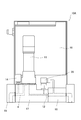
- FIG. 1 shows a gas supply system 1 in which a pressure type flow rate control device 10 according to an embodiment of the present invention is incorporated.
- the gas supply system 1 includes a gas supply source 2, a flow rate control device 10 provided in a flow path 4 forming a gas supply line, and an on-off valve (on / off valve) provided on the upstream side and the downstream side of the flow rate control device 10. ) 3, 5, a process chamber 6 connected to the downstream side of the on-off valve 5, and a vacuum pump 7 connected to the process chamber 6.
- the flow rate control device 10 is provided to control the flow rate of the gas flowing through the flow path 4.
- the vacuum pump 7 can evacuate the process chamber 6 and the flow path 4, and the flow-controlled gas is supplied to the process chamber 6 with the downstream side of the flow control device 10 depressurized.
- gases used in the semiconductor manufacturing process such as a raw material gas, an etching gas, or a carrier gas, may be supplied from the gas supply source 2.
- the on-off valves 3 and 5 are provided on the upstream side and the downstream side of the flow rate control device 10, but even if the on-off valve 5 on the downstream side is built in the outlet side of the flow rate control device 10. Good.
- valves having good shutoff and responsiveness for example, an air-driven valve (AOV), a solenoid valve (solenoid valve), and an electric valve are preferably used.
- FIG. 2 is a schematic view showing the configuration of the flow rate control device 10 of the present embodiment.
- the flow control device 10 is located between the control valve 11 interposed in the flow path 4, the throttle portion 12 provided on the downstream side of the control valve 11, and the control valve 11 and the throttle portion 12.
- the upstream pressure sensor 13 that measures the pressure (upstream pressure) P1
- the differential pressure sensor 20 that directly measures the differential pressure ⁇ P between the upstream side and the downstream side of the throttle portion 12, and the pressure on the upstream side of the control valve 11
- the inflow pressure sensor 14 for measuring the supply pressure) P0, the temperature sensor 15 for measuring the temperature T of the fluid, and the arithmetic control circuit 16 are provided.
- An upstream pressure sensor 13, a differential pressure sensor 20, an inflow pressure sensor 14, a temperature sensor 15, and the like are connected to the arithmetic control circuit 16, and the arithmetic control circuit 16 can receive the output of each sensor. Further, the arithmetic control circuit 16 is connected to the drive element of the control valve 11, adjusts the opening degree of the control valve 11 based on the output of each sensor, and controls the flow rate of the gas flowing downstream of the throttle portion 12. can do.
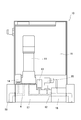
- FIG. 3 is a side view showing a specific configuration of the flow control device 10 of the present embodiment and a view showing an internal flow path (broken line).
- the flow path 4 is formed by providing holes in the main body block 17 and the outlet block 18.
- the main body block 17 and the outlet block 18 are preferably formed of a substance that does not react with the gas used, for example, stainless steel (SUS316L or the like).
- the temperature sensor 15 shown in FIG. 2 is not shown in FIG. 3, it can be used as a temperature sensor by providing a bottomed hole in the vicinity of the flow path 4 and arranging a thermistor or the like inside the hole. ..
- the primary side ports of the inflow pressure sensor 14, the control valve 11, the upstream pressure sensor 13, and the differential pressure sensor 20 are attached to the upper surface of the main body block 17, and these are circulated with the flow path 4 on the upstream side of the throttle portion 12. doing. Further, a secondary port of the differential pressure sensor 20 is connected to the upper surface of the outlet block 18 and circulates with the flow path 4 on the downstream side of the throttle portion 12.
- an orifice member as a throttle portion 12 is provided at the boundary between the main body block 17 and the outlet block 18, an orifice member as a throttle portion 12, more specifically, a gasket type orifice member having an orifice plate built-in.
- the throttle portion 12 is not limited to the orifice plate, and may be configured by using a sound velocity nozzle or the like.
- the diameter of the orifice or nozzle is set to, for example, 10 ⁇ m to 500 ⁇ m.
- the upstream pressure sensor 13 can measure the pressure in the flow path (upstream pressure P1) between the control valve 11 and the throttle portion 12, and is used for proportional flow rate control based on the upstream pressure P1. Further, the inflow pressure sensor 14 can measure the pressure (supply pressure P0) of the gas supplied from the gas supply source 2 (for example, the raw material vaporizer), and is used to adjust the gas supply amount or the supply pressure. ..
- the upstream pressure sensor 13 and the inflow pressure sensor 14 may include, for example, a silicon single crystal sensor chip and a diaphragm.
- differential pressure sensor 20 is configured to directly measure the differential pressure ⁇ P between the pressure between the control valve 11 and the throttle portion 12 and the pressure on the downstream side of the throttle portion 12. It is used to control the flow rate.
- the differential pressure sensor 20 may also include a silicon single crystal sensor chip and a diaphragm. The detailed configuration of the differential pressure sensor 20 will be described later.
- the control valve 11 may be, for example, a piezo element drive type valve composed of a metal diaphragm as a valve body and a piezo element (piezo actuator) as a drive device for driving the diaphragm.
- the opening degree of the piezo element drive type valve can be changed according to the drive voltage to the piezo element, and can be adjusted to an arbitrary opening degree by controlling the drive voltage.
- the inlet block 19 having an inflow port is fixed to the upstream side of the main body block 17 via a gasket
- the outlet block 18 having an outflow port is a gasket type orifice member (throttle) on the downstream side of the main body block 17. It is fixed via the portion 12).
- the inlet block 19 and the outlet block 18 are also formed of, for example, stainless steel (such as SUS316L).
- the flow path provided in the inlet block 19 and the outlet block 18 is formed to be relatively thick, whereas the flow path of the main body block 17 particularly between the control valve 11 and the throttle portion 12 is formed as thin as possible. Has been done. Further, the flow path on the downstream side of the control valve 11 extends so as to hang down from the central portion of the valve body of the control valve 11.
- the internal volume between the control valve 11 and the throttle portion 12 when the control valve 11 is closed can be minimized.
- the amount of gas flowing out through the throttle portion 12 after closing the control valve 11 is reduced, and the falling response can be improved.
- the diameter of the flow path on the downstream side of the control valve 11 is typically designed to be smaller than the diameter of the flow path on the upstream side of the control valve 11.
- the arithmetic control circuit 16 is composed of, for example, a processor or memory provided on a circuit board, includes a computer program that executes a predetermined arithmetic based on an input signal, and can be realized by a combination of hardware and software. .. In the illustrated embodiment, the arithmetic control circuit 16 is built in the flow rate control device 10, but some or all of its components (such as a CPU) may be provided outside the flow rate control device 10.
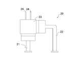
- the differential pressure sensor 20 includes a primary side connecting member 21 connected to the upstream side of the throttle portion 12, a secondary side connecting member 22 connected to the downstream side of the throttle portion 12, the primary side connecting member 21, and the secondary side. It is composed of a sensor body 23 connected to the connecting member 22.
- the primary side connecting member 21 is fixed to the lower surface of the sensor main body 23, and the secondary side connecting member 22 is fixed to the side surface of the sensor main body 23.
- the differential pressure sensor 20 is attached to the main body block 17 and the outlet block 18 so as to straddle the throttle portion 12.
- the secondary side connecting member 22 is preferably designed so that the connection position can be easily adjusted to some extent.
- the secondary side connecting member 22 is made of a thin metal bent into an L shape as a deformable piping member. It is constructed using a thin tube. As a result, even when a misalignment occurs when fixing the differential pressure sensor 20, the secondary side connecting member 22 can be deformed and fixed appropriately. A more flexible tube material can also be used as the secondary side connecting member 22.
- the upstream pressure P1 is transmitted to the sensor chip built in the sensor main body 23 via the primary side connecting member 21, and the downstream pressure P2 is transmitted to the same sensor chip via the secondary side connecting member 22. Is transmitted to.
- the pressure can be transmitted by using, for example, an encapsulating liquid for pressure transmission.
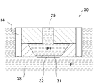
- FIG. 5 is a cross-sectional view showing a sensor chip 30 built in the sensor main body 23.
- the sensor chip 30 has a thin plate-shaped pressure-sensitive portion (diaphragm) 31.
- the pressure-sensitive portion 31 is formed, for example, by cutting a silicon single crystal.
- the pressure sensitive portion 31 one surface (here, the lower surface) of the pressure sensitive portion 31 is in contact with the first encapsulation liquid 28, and the other surface (here, the upper surface) is in contact with the second encapsulation liquid 29.
- the first encapsulation liquid 28 transmits the upstream pressure P1
- the second encapsulation liquid 29 transmits the downstream pressure P2.
- the upstream pressure P1 is transmitted to one surface of the pressure sensitive unit 31, and the downstream pressure P2 is transmitted to the other surface of the pressure sensitive unit 31.
- the sensor chip 30 is fixed to the sensor body 23 by a support member 34 that surrounds the sensor chip 30.
- the pressure sensitive portion 31 of the sensor chip 30 is provided with a strain sensor (or piezoresistive body) 32.
- the strain sensor 32 may be composed of a single unit or a plurality of strain sensors 32 as long as it can detect stress and strain generated in the pressure sensitive unit 31. Further, the mounting position is not limited to the illustrated mode.
- the output (change in electrical resistance value) of the strain sensor 32 arranged in the pressure sensitive unit 31 is transmitted to the arithmetic control circuit 16 via the wiring 24 (see FIG. 4) connected to the strain sensor 32.
- the upstream pressure P1 is transmitted to one surface of the pressure sensitive portion 31 of the sensor chip 30 through the first filling liquid 28. Further, the downstream pressure P2 is transmitted to the other surface of the pressure sensitive portion 31 of the sensor chip 30 through the second filling liquid 29. Then, a surface stress is generated in the pressure sensitive portion 31 according to the magnitude of the differential pressure between the upstream pressure P1 and the downstream pressure P2, and strain is generated according to the magnitude of the differential pressure.
- the magnitude of the strain of the pressure sensitive unit 31 is detected through the wiring 24 as a change in the electric resistance value of the strain sensor 32.
- the differential pressure sensor 20 does not indirectly obtain the differential pressure ⁇ P between the upstream pressure P1 and the downstream pressure P2 by subtracting it from the absolute value of each pressure, but directly uses the strain sensor 32. Can be measured.
- the strain sensor 32 is usually incorporated in a bridge circuit, and the amount of strain (change in resistance value) of the strain sensor 32 is output as a bridge output signal, and the differential pressure ⁇ P can be obtained from the bridge output signal. ..
- the upstream pressure P1 can be measured by using the upstream pressure sensor 13, and the differential pressure ⁇ P on both sides of the throttle portion 12 is measured by using the differential pressure sensor 20. Can be measured. Then, the flow rate control device 10 determines whether or not the critical expansion condition is satisfied based on the upstream pressure P1 and the differential pressure ⁇ P. More specifically, depending on whether (P1- ⁇ P) / P1 exceeds the threshold value corresponding to the critical pressure ratio (for example, 0.45), it is under critical expansion conditions or under non-critical expansion conditions. Determine if there is. As the threshold value, a value corresponding to all gas types may be used, or a value set for each gas type may be used.
- (P1- ⁇ P) is the pressure corresponding to the downstream pressure P2. However, it is not measured using the downstream pressure sensor, but is obtained by calculation from the measurement results of the upstream pressure sensor 13 and the differential pressure sensor 20. Therefore, in the present specification, for the sake of distinction, (P1- ⁇ P) obtained by calculation may be referred to as calculation downstream pressure P2'.
- the determination of whether or not the condition is critical expansion is not limited to that of whether or not P2'/ P1 exceeds the threshold value as described above.
- a threshold value for example, 2.2
- the ratio of the upstream pressure P1 output by the upstream pressure sensor to the calculated downstream pressure P2'obtained by subtracting the differential pressure ⁇ P output by the differential pressure sensor from the upstream pressure P1 is preset. The determination is made by comparing with the corresponding threshold.
- other appropriate determination formulas may be used as long as the upstream pressure P1 and the differential pressure ⁇ P are used. Further, it goes without saying that the determination may be made based on whether or not the threshold value is exceeded, not whether or not the threshold value is exceeded as described above.
- the arithmetic control circuit 16 obtains the difference between the calculated flow rate Qc obtained by the above equation and the input set flow rate Qs, and feedback-controls the opening degree of the control valve 11 so that the difference approaches 0. As a result, it is possible to flow the gas to the downstream side of the throttle portion 12 at the set flow rate Qs.
- the calculated flow rate Qc may be obtained according to the following equation.
- C1 is a coefficient including the orifice cross-sectional area
- P1 is the upstream pressure (Pa)
- T is the gas temperature (K)
- P2' is the calculated downstream pressure (Pa)
- m and n are derived from the actual flow rate. It is a constant.
- the calculated flow rate is corrected by using a correction data storage circuit that stores the relationship between the calculated downstream pressure P2'and the flow rate error. May be good.
- the flow rate control device 10 of the present embodiment employs various known flow rate control methods described in Patent Document 2 and the like, except that the calculated downstream pressure P2'is used instead of the downstream pressure P2 measured by the downstream pressure sensor. Can be done.
- the flow control device 10 of the present embodiment directly measures the differential pressure ⁇ P using the differential pressure sensor instead of using (P1-P2) calculated from the measured values of the upstream pressure sensor and the downstream pressure sensor.
- various known flow control methods described in Patent Document 2 and the like can be adopted.
- downstream pressure P2 by the downstream pressure sensor which is an absolute pressure sensor
- the calculated downstream pressure P2'by the upstream pressure sensor and the differential pressure sensor will be described.
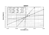
- FIG. 6 and 7 are graphs (simulation results) showing the relationship between the zero point fluctuation amount (kPa) of the pressure sensor and the differential pressure sensor and the flow rate error (% SP) in Examples and Comparative Examples, respectively.
- the embodiment of FIG. 6 corresponds to the case where the flow control device including the differential pressure sensor shown in FIG. 3 is used, and the comparative example of FIG. 7 corresponds to the upstream pressure sensor and the downstream as described in Patent Document 1.
- the zero point fluctuation amount means the difference (shift amount) between the true pressure and the measured pressure that occurs at any pressure, and an error that cannot be calibrated by the pressure sensor or long-term use of the pressure sensor. It corresponds to the deviation of the measured pressure that occurs with this, or the deviation of the measured pressure due to the temperature (temperature drift).
- fixed differential pressure sensor means that the differential pressure sensor does not have zero point fluctuation, while the P1 sensor has zero point fluctuation, and “fixed P1 sensor” means P1. It means that the zero point fluctuation does not occur in the sensor, but the zero point fluctuation occurs in the differential pressure sensor.
- fixed P2 sensor means that the P2 sensor does not have zero point fluctuation, while the P1 sensor has zero point fluctuation, and “fixed P1 sensor” means. This means that the P1 sensor has no zero point fluctuation, while the P2 sensor has zero point fluctuation.
- FIGS. 6 and 7 two types of graphs are shown, one is when the downstream pressure P2 is 100 Torr and the other is when the downstream pressure P2 is 400 Torr.
- a flow rate control device configured to flow gas at a 100% flow rate (maximum control flow rate) when the upstream pressure P1 is 2280 Torr
- the downstream pressure P2 when the downstream pressure P2 is 100 Torr, the upstream pressure P1 is 222 Torr (9.7% flow rate). If it is less than or equal to, differential pressure control is performed.
- the differential pressure control is performed at 39.0% or less. 6 and 7 show the relationship when differential pressure control is performed so that the gas flows at a flow rate of 4%.
- the flow rate error is ⁇ 1% S. P. Fits within. This can be said when the downstream pressure P2 is 100 Torr or 400 Torr, and the larger the downstream pressure P2, the smaller the degree of error that the zero point fluctuation of the P1 sensor gives to the flow rate accuracy.
- the flow rate error is ⁇ 1% S.I. P. If it is within the range, it can be generally considered that the flow rate control is performed with high accuracy. Below, the flow rate error is ⁇ 1% S.I. P. The amount of zero-point fluctuation that falls within the range is sometimes called the allowable fluctuation amount.
- the permissible fluctuation amount when the differential pressure sensor has a zero point fluctuation (fixed to the P1 sensor), when the downstream pressure P2 is relatively small as 100 Torr, the permissible fluctuation amount is about ⁇ 0.1 kPa. When the downstream pressure P2 is relatively large at 400 Torr, the permissible fluctuation amount is in a very narrow range of about ⁇ 0.02 kPa.
- the permissible fluctuation amount is narrow.
- the permissible fluctuation amount ⁇ is ⁇ 0.02 kPa, which is a very narrow range, regardless of whether the zero point fluctuation occurs in either the P1 sensor or the P2 sensor. ing.
- the flow rate control device of the embodiment has a larger permissible fluctuation amount than the flow rate control device of the comparative example. It can be seen that it is resistant to zero point deviation. Then, in the embodiment, the zero point fluctuation of the upstream pressure sensor is less likely to be reflected in the flow rate error as the downstream pressure P2 is larger. Therefore, it can be seen that the embodiment is more advantageous when the downstream pressure P2 is large and the flow rate is controlled at a small flow rate.
- the flow rate control device of the present embodiment using the differential pressure sensor has a feature that the zero point fluctuation of the differential pressure sensor is relatively unlikely to occur.
- the reason is that the zero point calibration of the differential pressure sensor can be properly performed regardless of the magnitude of the upstream pressure P1 and the downstream pressure P2 as long as they are the same, and the flow control device is in line. This is because calibration is possible by closing the valves provided in the front and rear even when mounted on the.
- the zero point calibration of the upstream pressure sensor and the downstream pressure sensor should ideally be performed in a state where the pressure is completely connected to a vacuum space of 0, but such a vacuum space is realized.
- the zero point fluctuation of the differential pressure sensor is relatively small, and even if the zero point fluctuation of the upstream pressure sensor occurs, the flow rate is relatively high accuracy. Control can be performed.
- the downstream pressure P2 is high and the zero point fluctuation of the upstream pressure sensor is not easily reflected in the flow rate error even when controlling a small flow rate, the flow rate control can be appropriately performed over a wide control range.
- FIGS. 8 and 9 The elements having the same configuration as the flow rate control device 10 of the embodiment shown in FIGS. 3 to 5 may be designated by the same reference numerals and the description thereof may be omitted.
- FIG. 8 is a side view showing a specific configuration of the flow rate control device 10A and a view showing an internal flow path (broken line).
- the flow control device 10A unlike the flow control device 10 shown in FIG. 3, instead of providing the upstream pressure sensor and the differential pressure sensor separately, the upstream pressure sensor and the differential pressure sensor are integrally formed. A body type sensor 35 is provided.
- the primary side port of the integrated sensor 35 is connected to the upstream side (main body block 17) of the throttle portion 12, and the secondary side port of the integrated sensor 35 is connected to the downstream side (exit block 18) of the throttle portion 12.
- the integrated sensor 35 can also be attached by using the attachment portion for the upstream pressure sensor and the attachment portion for the downstream pressure sensor provided in the main body block of the conventional flow control device.
- FIG. 9 is a cross-sectional view showing the configuration of the sensor chip 30A included in the integrated sensor 35.
- the first filling liquid 28 is in contact with both the pressure-sensitive portion 31 for measuring the differential pressure ⁇ P and the second pressure-sensitive portion 37 for measuring the upstream pressure P1.
- the second encapsulating liquid 29 is in contact with the facing surface of the pressure sensitive portion 31, and the differential pressure ⁇ P between the upstream pressure P1 and the downstream pressure P2 using the strain sensor 32. Can be measured.
- the facing surface of the second pressure sensitive portion 37 is in contact with the vacuum chamber 36 whose inside is kept at the vacuum pressure Pv.
- the strain sensor 38 attached to the second pressure-sensitive unit 37 can detect the stress generated in the second pressure-sensitive unit 37, that is, the stress corresponding to the magnitude of the upstream pressure P1.
- both the upstream pressure P1 and the differential pressure ⁇ P can be measured independently. Therefore, it is not necessary to separately provide the upstream pressure sensor and the differential pressure sensor, which can contribute to the compactification of the device and further convenience can be obtained.
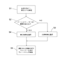
- step S1 the upstream pressure P1 and the differential pressure ⁇ P are measured using the upstream pressure sensor and the differential pressure sensor (or the integrated sensor).
- step S2 it is determined whether or not the critical expansion conditions are met. More specifically, it is determined whether or not (P1- ⁇ P) / P1 obtained by the measurement in step S1 exceeds the threshold value.
- step S2 If the threshold value is not exceeded in step S2, it is determined that the critical expansion condition is met, and in step S3, the proportional control method based on the upstream pressure P1 is selected. On the other hand, when the threshold value is exceeded in step S2, the differential pressure control method based on the upstream pressure P1 and the differential pressure ⁇ P is selected in step S4.
- step S5 the control valve can be feedback-controlled according to any of the selected control methods, and the gas can flow at the set flow rate.
- the upstream pressure sensor and the differential pressure sensor it is possible to appropriately determine whether or not the conditions are critical expansion conditions, and select the appropriate control from the proportional control and the differential pressure control. can do. Then, according to the selected control method, the flow rate can be appropriately controlled over a wide flow rate range while the influence of the sensor error is reduced.
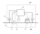
- FIG. 11 shows the flow rate control device 10B according to still another embodiment.
- the flow rate control device 10B includes a control valve 11, a throttle portion 12, a differential pressure sensor 20, an inflow pressure sensor 14, a temperature sensor 15, and an arithmetic control circuit 16. .
- the flow rate control device 10B has a downstream pressure sensor 13B instead of the upstream pressure sensor 13 of the flow rate control device 10.
- FIG. 12 is a side view showing a specific configuration of the flow rate control device 10B.
- the inflow pressure sensor 14, the control valve 11, and the primary side port of the differential pressure sensor 20 are attached to the upper surface of the main body block 17, and these are circulated with the flow path on the upstream side of the throttle portion 12. Further, a secondary port of the differential pressure sensor 20 is connected to the upper surface of the outlet block 18 and circulates with a flow path on the downstream side of the throttle portion 12.
- the downstream pressure sensor 13B is fixed on the upper surface of the outlet glock 18.
- the downstream pressure sensor 13B can measure the pressure (downstream pressure P2) of the flow path on the downstream side of the throttle portion 12.
- the downstream pressure sensor 13B may include, for example, a silicon single crystal sensor chip and a diaphragm.
- the differential pressure sensor 20 is configured to directly measure the differential pressure ⁇ P between the pressure between the control valve 11 and the throttle portion 12 and the pressure on the downstream side of the throttle portion 12. It is used to control the differential pressure flow rate.
- the differential pressure sensor 20 may have the same configuration as that of the above-described embodiment.
- the flow rate control device 10B is not provided with the upstream pressure sensor 13. Therefore, the volume Vs between the control valve 11 and the throttle portion 12 is further reduced. As a result, the gas flows out faster through the throttle portion 12 after the control valve 11 is closed, and the falling response can be further improved as compared with the flow rate control device 10.
- the flow rate control device 10B is configured to control the flow rate of the gas flowing downstream of the throttle portion 12 by using the differential pressure ⁇ P output by the differential pressure sensor 20 and the downstream pressure P2 output by the downstream pressure sensor 13B. Has been done.
- the flow rate control device 10B determines whether or not the critical expansion condition is satisfied based on the differential pressure ⁇ P and the downstream pressure P2.
- P2 / ( ⁇ P + P2) is a threshold value corresponding to the critical pressure ratio (for example, 0). It is determined whether the condition is a critical expansion condition or a non-critical expansion condition depending on whether or not it exceeds .45).
- ( ⁇ P + P2) is the pressure corresponding to the upstream pressure P1.
- ( ⁇ P + P2) obtained by calculation may be referred to as calculation upstream pressure P1'.
- it is determined whether or not the critical expansion condition is satisfied by comparing the ratio of the calculated upstream pressure P1'and the downstream pressure P2 with a preset threshold value.
- the flow rate is controlled by differential pressure control based on the pressure P1'or the differential pressure ⁇ P and the downstream pressure P2.
- K1 and K2 are proportional coefficients depending on the type of fluid and the fluid temperature, and the indices m and n are constants derived from the actual flow rate.
- the arithmetic control circuit 16 obtains the difference between the calculated flow rate Qc obtained by the above equation and the input set flow rate Qs, and feedback-controls the opening degree of the control valve 11 so that the difference approaches 0. As a result, it is possible to flow the gas to the downstream side of the throttle portion 12 at the set flow rate Qs.
- the differential pressure control may be performed by obtaining the calculated flow rate Qc according to the following equation in the same manner as the method described in Patent Document 2.
- C1 is a coefficient including the orifice cross-sectional area
- P1 is the upstream pressure (Pa)
- T is the gas temperature (K)
- P2' is the calculated downstream pressure (Pa)
- m and n are derived from the actual flow rate. It is a constant.
- the flow control device 10B of the present embodiment obtains by calculation from the measured values of the upstream pressure sensor and the downstream pressure sensor, except that the calculated upstream pressure P1'is used instead of using the upstream pressure P1 measured by the upstream pressure sensor.
- Various known flow control methods described in Patent Document 2 and the like can be adopted except that the differential pressure ⁇ P directly measured by using the differential pressure sensor is used instead of using (P1-P2).
- the differential pressure ⁇ P output by the differential pressure sensor 20 is regarded as the upstream pressure P1.
- the differential pressure sensor 20 is also used in the flow rate control device 10B described above, it is difficult for the influence of the zero point fluctuation that may occur in the pressure sensor to be reflected in the flow rate control, and both the proportional control and the differential pressure control are performed. Since this can be performed, the flow rate can be controlled accurately under both critical expansion conditions and non-critical expansion conditions. Therefore, the flow rate can be appropriately controlled over a wide control range.
- the flow rate control device is suitably used for accurately controlling the flow rate in a wide control range.
- Gas supply system Gas supply source 3, 5 On-off valve 4 Flow path (gas supply line) 6 Process chamber 7 Vacuum pump 10 Flow control device 11 Control valve 12 Squeezing part 13 Upstream pressure sensor 13B Downstream pressure sensor 14 Inflow pressure sensor 15 Temperature sensor 16 Computational control circuit 17 Main body block 18 Outlet block 19 Inlet block 20 Differential pressure sensor 21 Primary Side connection member 22 Secondary side connection member 23 Sensor body 30 Sensor chip 31 Pressure sensitive part 32 Strain sensor 35 Integrated sensor
Landscapes
- Physics & Mathematics (AREA)
- General Physics & Mathematics (AREA)
- Fluid Mechanics (AREA)
- Engineering & Computer Science (AREA)
- Automation & Control Theory (AREA)
- Flow Control (AREA)
- Measuring Volume Flow (AREA)
Abstract
Description
Qc=C1・P1/√T・((P2’/P1)m-(P2’/P1)n)1/2
=C1・P1/√T・(((P1-ΔP)/P1)m-((P1-ΔP)/P1)n)1/2
上記式において、C1はオリフィス断面積を含む係数、P1は上流圧力(Pa)、Tはガス温度(K)、P2’は演算下流圧力(Pa)、mおよびnは実際の流量から導出された定数である。
Qc=C1・P1’/√T・((P2/P1’)m-(P2/P1’)n)1/2
=C1・(ΔP+P2)/√T・((P2/(ΔP+P2))m-(P2/(ΔP+P2))n)1/2
上記式において、C1はオリフィス断面積を含む係数、P1は上流圧力(Pa)、Tはガス温度(K)、P2’は演算下流圧力(Pa)、mおよびnは実際の流量から導出された定数である。
2 ガス供給源
3、5 開閉弁
4 流路(ガス供給ライン)
6 プロセスチャンバ
7 真空ポンプ
10 流量制御装置
11 コントロール弁
12 絞り部
13 上流圧力センサ
13B 下流圧力センサ
14 流入圧力センサ
15 温度センサ
16 演算制御回路
17 本体ブロック
18 出口ブロック
19 入口ブロック
20 差圧センサ
21 一次側接続部材
22 二次側接続部材
23 センサ本体
30 センサチップ
31 感圧部
32 歪センサ
35 一体型センサ
Claims (13)
- コントロール弁と、
前記コントロール弁の下流側に設けられた絞り部と、
前記コントロール弁と前記絞り部との間の圧力を測定する上流圧力センサと、
前記絞り部の上流側と下流側との差圧を測定する差圧センサと、
前記コントロール弁、前記上流圧力センサおよび前記差圧センサに接続された演算制御回路と
を備える、流量制御装置。 - 前記演算制御回路は、前記上流圧力センサの出力と前記差圧センサの出力とに基づいて決定される演算流量が設定流量となるように前記コントロール弁の制御を行う、請求項1に記載の流量制御装置。
- 前記コントロール弁の制御は、演算流量QcがQc=K2・(P1-ΔP)mΔPnまたはQc=C1・P1/√T・(((P1-ΔP)/P1)m-((P1-ΔP)/P1)n)1/2に従って決定される差圧制御を含み、上記式において、P1は、前記上流圧力センサが出力する上流圧力、ΔPは前記差圧センサが出力する差圧、K2は流体の種類と流体温度に依存する比例係数、m、nは実際の流量から導出された定数、C1はオリフィス断面積を含む係数、Tはガス温度である、請求項2に記載の流量制御装置。
- 前記コントロール弁の制御は、演算流量QcがQc=K1・P1に従って決定される比例制御をさらに含み、上記式においてK1は流体の種類と流体温度に依存する比例係数である、請求項3に記載の流量制御装置。
- 前記上流圧力センサの出力と、前記上流圧力センサの出力から前記差圧センサの出力を減算することによって得られる演算下流圧力との比を、予め設定された閾値と比較することによって、前記比例制御または前記差圧制御のいずれかに決定される、請求項4に記載の流量制御装置。
- 前記差圧センサは、
前記絞り部の上流側の流路に接続される一次側接続部材と、
前記絞り部の下流側の流路に接続される二次側接続部材と、
前記一次側接続部材および前記二次側接続部材に接続され、差圧を測定するセンサチップを内蔵するセンサ本体とを備え、
前記センサチップは、
前記絞り部の上流側の圧力が伝達される一方の面と前記絞り部の下流側の圧力が伝達される他方の面とを有する感圧部と、
前記感圧部の歪を検知する歪センサとを含む、請求項1から5のいずれかに記載の流量制御装置。 - 前記二次側接続部材は、接続位置調整可能な配管部材を備える、請求項6に記載の流量制御装置。
- 前記上流圧力センサと前記差圧センサとが一体的に形成されている、請求項1から7のいずれかに記載の流量制御装置。
- コントロール弁と、
前記コントロール弁の下流側に設けられた絞り部と、
前記絞り部の上流側と下流側との差圧を測定する差圧センサと、
前記絞り部の下流側の圧力を測定する下流圧力センサと、
前記コントロール弁、前記差圧センサおよび前記下流圧力センサに接続された演算制御回路と
を備える、流量制御装置。 - 前記演算制御回路は、前記差圧センサの出力と前記下流圧力センサの出力とに基づいて決定される演算流量が設定流量となるように前記コントロール弁の制御を行う、請求項9に記載の流量制御装置。
- 前記コントロール弁の制御は、演算流量QcがQc=K2・P2m・ΔPnまたはQc=C1・(ΔP+P2)/√T・((P2/(ΔP+P2))m-(P2/(ΔP+P2))n)1/2に従って決定される差圧制御を含み、上記式において、ΔPは前記差圧センサが出力する差圧、P2は前記下流圧力センサが出力する下流圧力、K2は流体の種類と流体温度に依存する比例係数、m、nは実際の流量から導出された定数、C1はオリフィス断面積を含む係数、Tはガス温度である、請求項10に記載の流量制御装置。
- 前記コントロール弁の制御は、演算流量QcがQc=K1・(ΔP+P2)に従って決定される比例制御をさらに含み、上記式においてK1は流体の種類と流体温度に依存する比例係数である、請求項11に記載の流量制御装置。
- 前記差圧センサの出力に前記下流圧力センサの出力を加算することによって得られる演算上流圧力と、前記下流圧力センサの出力との比を、予め設定された閾値と比較することによって、前記比例制御または前記差圧制御のいずれかに決定される、請求項12に記載の流量制御装置。
Priority Applications (6)
| Application Number | Priority Date | Filing Date | Title |
|---|---|---|---|
| JP2021516046A JP7495742B2 (ja) | 2019-04-25 | 2020-04-16 | 流量制御装置および流量制御方法 |
| CN202080024764.8A CN113632038A (zh) | 2019-04-25 | 2020-04-16 | 流量控制装置 |
| KR1020217032886A KR20210139347A (ko) | 2019-04-25 | 2020-04-16 | 유량 제어 장치 |
| US17/605,948 US11914407B2 (en) | 2019-04-25 | 2020-04-16 | Flow rate control device |
| KR1020247011178A KR102771309B1 (ko) | 2019-04-25 | 2020-04-16 | 유량 제어 장치 |
| US18/418,644 US12174647B2 (en) | 2019-04-25 | 2024-01-22 | Flow rate control device |
Applications Claiming Priority (2)
| Application Number | Priority Date | Filing Date | Title |
|---|---|---|---|
| JP2019083562 | 2019-04-25 | ||
| JP2019-083562 | 2019-04-25 |
Related Child Applications (2)
| Application Number | Title | Priority Date | Filing Date |
|---|---|---|---|
| US17/605,948 A-371-Of-International US11914407B2 (en) | 2019-04-25 | 2020-04-16 | Flow rate control device |
| US18/418,644 Division US12174647B2 (en) | 2019-04-25 | 2024-01-22 | Flow rate control device |
Publications (1)
| Publication Number | Publication Date |
|---|---|
| WO2020218138A1 true WO2020218138A1 (ja) | 2020-10-29 |
Family
ID=72942011
Family Applications (1)
| Application Number | Title | Priority Date | Filing Date |
|---|---|---|---|
| PCT/JP2020/016674 Ceased WO2020218138A1 (ja) | 2019-04-25 | 2020-04-16 | 流量制御装置 |
Country Status (6)
| Country | Link |
|---|---|
| US (2) | US11914407B2 (ja) |
| JP (1) | JP7495742B2 (ja) |
| KR (2) | KR102771309B1 (ja) |
| CN (1) | CN113632038A (ja) |
| TW (1) | TWI747245B (ja) |
| WO (1) | WO2020218138A1 (ja) |
Families Citing this family (6)
| Publication number | Priority date | Publication date | Assignee | Title |
|---|---|---|---|---|
| WO2020218138A1 (ja) | 2019-04-25 | 2020-10-29 | 株式会社フジキン | 流量制御装置 |
| JP7805174B2 (ja) * | 2022-01-14 | 2026-01-23 | 株式会社堀場エステック | 流体制御装置、流体制御方法、及び、流体制御プログラム |
| CN118567397A (zh) * | 2023-02-28 | 2024-08-30 | 北京七星华创流量计有限公司 | 气体质量流量控制器及方法 |
| CN117148877B (zh) * | 2023-11-01 | 2024-01-02 | 苏芯物联技术(南京)有限公司 | 一种高精度管道流量测量控制装置及设计方法 |
| CN118817008B (zh) * | 2024-07-10 | 2026-04-07 | 山东仁甬得工业科技有限公司 | 一种流量计 |
| CN118661626B (zh) * | 2024-07-25 | 2025-05-27 | 宁夏回族自治区水利科学研究院 | 地形适应型滴灌系统的水压动态平衡调节方法 |
Citations (5)
| Publication number | Priority date | Publication date | Assignee | Title |
|---|---|---|---|---|
| JP2004138425A (ja) * | 2002-10-16 | 2004-05-13 | Tadahiro Omi | 圧力式流量制御装置の温度測定装置 |
| WO2008053839A1 (fr) * | 2006-11-02 | 2008-05-08 | Horiba Stec, Co., Ltd. | Mécanisme de diagnostic dans un régulateur de débit massique à pression différentielle |
| JP4204400B2 (ja) * | 2003-07-03 | 2009-01-07 | 忠弘 大見 | 差圧式流量計及び差圧式流量制御装置 |
| JP2013185873A (ja) * | 2012-03-06 | 2013-09-19 | Azbil Corp | 差圧センサ |
| WO2017057129A1 (ja) * | 2015-09-30 | 2017-04-06 | 日立金属株式会社 | 質量流量制御装置、及び差圧式流量計の診断方法 |
Family Cites Families (43)
| Publication number | Priority date | Publication date | Assignee | Title |
|---|---|---|---|---|
| JPH043244Y2 (ja) * | 1985-11-29 | 1992-02-03 | ||
| JP3580645B2 (ja) * | 1996-08-12 | 2004-10-27 | 忠弘 大見 | 圧力式流量制御装置 |
| US5865205A (en) * | 1997-04-17 | 1999-02-02 | Applied Materials, Inc. | Dynamic gas flow controller |
| JP3522535B2 (ja) * | 1998-05-29 | 2004-04-26 | 忠弘 大見 | 圧力式流量制御装置を備えたガス供給設備 |
| US6119710A (en) * | 1999-05-26 | 2000-09-19 | Cyber Instrument Technologies Llc | Method for wide range gas flow system with real time flow measurement and correction |
| US6581623B1 (en) * | 1999-07-16 | 2003-06-24 | Advanced Technology Materials, Inc. | Auto-switching gas delivery system utilizing sub-atmospheric pressure gas supply vessels |
| US6539968B1 (en) * | 2000-09-20 | 2003-04-01 | Fugasity Corporation | Fluid flow controller and method of operation |
| US6564824B2 (en) * | 2001-04-13 | 2003-05-20 | Flowmatrix, Inc. | Mass flow meter systems and methods |
| KR20040019293A (ko) * | 2001-05-24 | 2004-03-05 | 셀레리티 그룹 아이엔씨 | 소정 비율의 프로세스 유체를 제공하는 방법 및 장치 |
| US20030098069A1 (en) * | 2001-11-26 | 2003-05-29 | Sund Wesley E. | High purity fluid delivery system |
| JP4102564B2 (ja) * | 2001-12-28 | 2008-06-18 | 忠弘 大見 | 改良型圧力式流量制御装置 |
| JP3856730B2 (ja) * | 2002-06-03 | 2006-12-13 | 東京エレクトロン株式会社 | 流量制御装置を備えたガス供給設備からのチャンバーへのガス分流供給方法。 |
| US6997202B2 (en) * | 2002-12-17 | 2006-02-14 | Advanced Technology Materials, Inc. | Gas storage and dispensing system for variable conductance dispensing of gas at constant flow rate |
| US7740024B2 (en) * | 2004-02-12 | 2010-06-22 | Entegris, Inc. | System and method for flow monitoring and control |
| JP4086057B2 (ja) * | 2004-06-21 | 2008-05-14 | 日立金属株式会社 | 質量流量制御装置及びこの検定方法 |
| US7205060B2 (en) * | 2004-08-06 | 2007-04-17 | Ultracell Corporation | Method and system for controlling fluid delivery in a fuel cell |
| US9383758B2 (en) * | 2005-06-27 | 2016-07-05 | Fujikin Incorporated | Flow rate range variable type flow rate control apparatus |
| US20100269924A1 (en) * | 2007-12-27 | 2010-10-28 | Horiba Stec, Co., Ltd. | Flow rate ratio controlling apparatus |
| WO2009141947A1 (ja) * | 2008-05-21 | 2009-11-26 | 株式会社フジキン | 圧力式流量制御装置を用いた流体の非連続式流量切替制御方法 |
| JP5562712B2 (ja) * | 2010-04-30 | 2014-07-30 | 東京エレクトロン株式会社 | 半導体製造装置用のガス供給装置 |
| TW201234155A (en) * | 2010-07-09 | 2012-08-16 | Entegris Inc | Flow controller |
| KR101599343B1 (ko) * | 2011-05-10 | 2016-03-03 | 가부시키가이샤 후지킨 | 유량 모니터 부착 압력식 유량 제어 장치 |
| US8840578B2 (en) * | 2011-12-09 | 2014-09-23 | Alcon Research, Ltd. | Multilayer membrane actuators |
| US9846074B2 (en) * | 2012-01-20 | 2017-12-19 | Mks Instruments, Inc. | System for and method of monitoring flow through mass flow controllers in real time |
| JP5887188B2 (ja) * | 2012-04-12 | 2016-03-16 | 株式会社堀場エステック | 流体制御用機器 |
| JP5665794B2 (ja) * | 2012-04-27 | 2015-02-04 | 株式会社フジキン | 半導体製造装置のガス分流供給装置 |
| US9454158B2 (en) * | 2013-03-15 | 2016-09-27 | Bhushan Somani | Real time diagnostics for flow controller systems and methods |
| JP5847106B2 (ja) * | 2013-03-25 | 2016-01-20 | 株式会社フジキン | 流量モニタ付圧力式流量制御装置。 |
| JP5797246B2 (ja) * | 2013-10-28 | 2015-10-21 | 株式会社フジキン | 流量計及びそれを備えた流量制御装置 |
| JP6415889B2 (ja) * | 2014-08-01 | 2018-10-31 | 株式会社堀場エステック | 流量制御装置、流量制御装置用プログラム、及び、流量制御方法 |
| KR102028372B1 (ko) * | 2015-09-24 | 2019-10-04 | 가부시키가이샤 후지킨 | 압력식 유량 제어 장치 및 그 이상 검지 방법 |
| KR102121260B1 (ko) * | 2015-12-25 | 2020-06-10 | 가부시키가이샤 후지킨 | 유량 제어 장치 및 유량 제어 장치를 사용하는 이상 검지 방법 |
| CN108885471B (zh) * | 2016-03-29 | 2021-10-01 | 株式会社富士金 | 压力式流量控制装置和流量自诊断方法 |
| WO2018047644A1 (ja) * | 2016-09-12 | 2018-03-15 | 株式会社堀場エステック | 流量比率制御装置、流量比率制御装置用プログラム、及び、流量比率制御方法 |
| US10866131B2 (en) * | 2016-09-19 | 2020-12-15 | Flow Devices And Systems Inc. | Systems and methods for reference volume for flow calibration |
| WO2018070464A1 (ja) * | 2016-10-14 | 2018-04-19 | 株式会社フジキン | 流体制御装置 |
| CN110431508A (zh) * | 2017-03-28 | 2019-11-08 | 株式会社富士金 | 压力式流量控制裝置以及流量控制方法 |
| JP7097085B2 (ja) * | 2017-07-25 | 2022-07-07 | 株式会社フジキン | 流体制御装置 |
| CN111406243A (zh) * | 2017-11-30 | 2020-07-10 | 株式会社富士金 | 流量控制装置 |
| US11073846B2 (en) * | 2018-01-30 | 2021-07-27 | Illinois Tool Works Inc. | Mass flow controller with absolute and differential pressure transducer |
| JP7068062B2 (ja) * | 2018-06-18 | 2022-05-16 | 株式会社堀場製作所 | 流体制御装置、及び、流量比率制御装置 |
| JP2020021176A (ja) * | 2018-07-30 | 2020-02-06 | 株式会社堀場エステック | 流量制御装置 |
| WO2020218138A1 (ja) * | 2019-04-25 | 2020-10-29 | 株式会社フジキン | 流量制御装置 |
-
2020
- 2020-04-16 WO PCT/JP2020/016674 patent/WO2020218138A1/ja not_active Ceased
- 2020-04-16 US US17/605,948 patent/US11914407B2/en active Active
- 2020-04-16 KR KR1020247011178A patent/KR102771309B1/ko active Active
- 2020-04-16 CN CN202080024764.8A patent/CN113632038A/zh active Pending
- 2020-04-16 KR KR1020217032886A patent/KR20210139347A/ko not_active Ceased
- 2020-04-16 JP JP2021516046A patent/JP7495742B2/ja active Active
- 2020-04-24 TW TW109113762A patent/TWI747245B/zh active
-
2024
- 2024-01-22 US US18/418,644 patent/US12174647B2/en active Active
Patent Citations (5)
| Publication number | Priority date | Publication date | Assignee | Title |
|---|---|---|---|---|
| JP2004138425A (ja) * | 2002-10-16 | 2004-05-13 | Tadahiro Omi | 圧力式流量制御装置の温度測定装置 |
| JP4204400B2 (ja) * | 2003-07-03 | 2009-01-07 | 忠弘 大見 | 差圧式流量計及び差圧式流量制御装置 |
| WO2008053839A1 (fr) * | 2006-11-02 | 2008-05-08 | Horiba Stec, Co., Ltd. | Mécanisme de diagnostic dans un régulateur de débit massique à pression différentielle |
| JP2013185873A (ja) * | 2012-03-06 | 2013-09-19 | Azbil Corp | 差圧センサ |
| WO2017057129A1 (ja) * | 2015-09-30 | 2017-04-06 | 日立金属株式会社 | 質量流量制御装置、及び差圧式流量計の診断方法 |
Also Published As
| Publication number | Publication date |
|---|---|
| US11914407B2 (en) | 2024-02-27 |
| US12174647B2 (en) | 2024-12-24 |
| CN113632038A (zh) | 2021-11-09 |
| US20220197316A1 (en) | 2022-06-23 |
| KR102771309B1 (ko) | 2025-02-24 |
| TW202102961A (zh) | 2021-01-16 |
| US20240160230A1 (en) | 2024-05-16 |
| JP7495742B2 (ja) | 2024-06-05 |
| KR20210139347A (ko) | 2021-11-22 |
| JPWO2020218138A1 (ja) | 2020-10-29 |
| KR20240052061A (ko) | 2024-04-22 |
| TWI747245B (zh) | 2021-11-21 |
Similar Documents
| Publication | Publication Date | Title |
|---|---|---|
| US12174647B2 (en) | Flow rate control device | |
| TWI796417B (zh) | 具有絕對和差分壓力變換器之質量流量控制器及其相關方法 | |
| JP6795832B2 (ja) | 流量制御機器、流量制御機器の流量校正方法、流量測定機器および流量測定機器を用いた流量測定方法 | |
| JP5797246B2 (ja) | 流量計及びそれを備えた流量制御装置 | |
| JP2015087110A5 (ja) | ||
| JP4977669B2 (ja) | 差圧式流量計 | |
| JP7244940B2 (ja) | 流量制御システム及び流量測定方法 | |
| TWI762082B (zh) | 壓力控制裝置 | |
| JP7131561B2 (ja) | 質量流量制御システム並びに当該システムを含む半導体製造装置及び気化器 | |
| JP2025019670A (ja) | 流量制御装置 | |
| JP4852654B2 (ja) | 圧力式流量制御装置 | |
| KR101668483B1 (ko) | 매스플로우 컨트롤러 | |
| JP2023163311A (ja) | 流量測定装置、流量測定方法および流量制御装置の校正方法 | |
| JP2025093734A (ja) | 流量測定装置 | |
| JP2009116904A (ja) | 圧力式流量制御装置 | |
| WO2025211124A1 (ja) | 流量測定装置および流体制御装置 |
Legal Events
| Date | Code | Title | Description |
|---|---|---|---|
| 121 | Ep: the epo has been informed by wipo that ep was designated in this application |
Ref document number: 20795966 Country of ref document: EP Kind code of ref document: A1 |
|
| ENP | Entry into the national phase |
Ref document number: 2021516046 Country of ref document: JP Kind code of ref document: A |
|
| ENP | Entry into the national phase |
Ref document number: 20217032886 Country of ref document: KR Kind code of ref document: A |
|
| NENP | Non-entry into the national phase |
Ref country code: DE |
|
| 122 | Ep: pct application non-entry in european phase |
Ref document number: 20795966 Country of ref document: EP Kind code of ref document: A1 |