WO2020217933A1 - 空調システム - Google Patents
空調システム Download PDFInfo
- Publication number
- WO2020217933A1 WO2020217933A1 PCT/JP2020/015361 JP2020015361W WO2020217933A1 WO 2020217933 A1 WO2020217933 A1 WO 2020217933A1 JP 2020015361 W JP2020015361 W JP 2020015361W WO 2020217933 A1 WO2020217933 A1 WO 2020217933A1
- Authority
- WO
- WIPO (PCT)
- Prior art keywords
- temperature
- humidity
- control unit
- target
- conditioning system
- Prior art date
Links
Images


Classifications
-
- F—MECHANICAL ENGINEERING; LIGHTING; HEATING; WEAPONS; BLASTING
- F24—HEATING; RANGES; VENTILATING
- F24F—AIR-CONDITIONING; AIR-HUMIDIFICATION; VENTILATION; USE OF AIR CURRENTS FOR SCREENING
- F24F11/00—Control or safety arrangements
- F24F11/62—Control or safety arrangements characterised by the type of control or by internal processing, e.g. using fuzzy logic, adaptive control or estimation of values
- F24F11/63—Electronic processing
- F24F11/65—Electronic processing for selecting an operating mode
-
- F—MECHANICAL ENGINEERING; LIGHTING; HEATING; WEAPONS; BLASTING
- F24—HEATING; RANGES; VENTILATING
- F24F—AIR-CONDITIONING; AIR-HUMIDIFICATION; VENTILATION; USE OF AIR CURRENTS FOR SCREENING
- F24F7/00—Ventilation
- F24F7/007—Ventilation with forced flow
-
- F—MECHANICAL ENGINEERING; LIGHTING; HEATING; WEAPONS; BLASTING
- F24—HEATING; RANGES; VENTILATING
- F24F—AIR-CONDITIONING; AIR-HUMIDIFICATION; VENTILATION; USE OF AIR CURRENTS FOR SCREENING
- F24F11/00—Control or safety arrangements
- F24F11/62—Control or safety arrangements characterised by the type of control or by internal processing, e.g. using fuzzy logic, adaptive control or estimation of values
- F24F11/63—Electronic processing
- F24F11/64—Electronic processing using pre-stored data
-
- F—MECHANICAL ENGINEERING; LIGHTING; HEATING; WEAPONS; BLASTING
- F24—HEATING; RANGES; VENTILATING
- F24F—AIR-CONDITIONING; AIR-HUMIDIFICATION; VENTILATION; USE OF AIR CURRENTS FOR SCREENING
- F24F2110/00—Control inputs relating to air properties
- F24F2110/10—Temperature
-
- F—MECHANICAL ENGINEERING; LIGHTING; HEATING; WEAPONS; BLASTING
- F24—HEATING; RANGES; VENTILATING
- F24F—AIR-CONDITIONING; AIR-HUMIDIFICATION; VENTILATION; USE OF AIR CURRENTS FOR SCREENING
- F24F2110/00—Control inputs relating to air properties
- F24F2110/10—Temperature
- F24F2110/12—Temperature of the outside air
-
- F—MECHANICAL ENGINEERING; LIGHTING; HEATING; WEAPONS; BLASTING
- F24—HEATING; RANGES; VENTILATING
- F24F—AIR-CONDITIONING; AIR-HUMIDIFICATION; VENTILATION; USE OF AIR CURRENTS FOR SCREENING
- F24F2110/00—Control inputs relating to air properties
- F24F2110/20—Humidity
-
- F—MECHANICAL ENGINEERING; LIGHTING; HEATING; WEAPONS; BLASTING
- F24—HEATING; RANGES; VENTILATING
- F24F—AIR-CONDITIONING; AIR-HUMIDIFICATION; VENTILATION; USE OF AIR CURRENTS FOR SCREENING
- F24F2110/00—Control inputs relating to air properties
- F24F2110/20—Humidity
- F24F2110/22—Humidity of the outside air
-
- F—MECHANICAL ENGINEERING; LIGHTING; HEATING; WEAPONS; BLASTING
- F24—HEATING; RANGES; VENTILATING
- F24F—AIR-CONDITIONING; AIR-HUMIDIFICATION; VENTILATION; USE OF AIR CURRENTS FOR SCREENING
- F24F2110/00—Control inputs relating to air properties
- F24F2110/50—Air quality properties
- F24F2110/65—Concentration of specific substances or contaminants
- F24F2110/70—Carbon dioxide
-
- F—MECHANICAL ENGINEERING; LIGHTING; HEATING; WEAPONS; BLASTING
- F24—HEATING; RANGES; VENTILATING
- F24F—AIR-CONDITIONING; AIR-HUMIDIFICATION; VENTILATION; USE OF AIR CURRENTS FOR SCREENING
- F24F2120/00—Control inputs relating to users or occupants
- F24F2120/10—Occupancy
-
- F—MECHANICAL ENGINEERING; LIGHTING; HEATING; WEAPONS; BLASTING
- F24—HEATING; RANGES; VENTILATING
- F24F—AIR-CONDITIONING; AIR-HUMIDIFICATION; VENTILATION; USE OF AIR CURRENTS FOR SCREENING
- F24F2120/00—Control inputs relating to users or occupants
- F24F2120/10—Occupancy
- F24F2120/14—Activity of occupants
-
- F—MECHANICAL ENGINEERING; LIGHTING; HEATING; WEAPONS; BLASTING
- F24—HEATING; RANGES; VENTILATING
- F24F—AIR-CONDITIONING; AIR-HUMIDIFICATION; VENTILATION; USE OF AIR CURRENTS FOR SCREENING
- F24F2120/00—Control inputs relating to users or occupants
- F24F2120/20—Feedback from users
Definitions
- This disclosure relates to an air conditioning system.
- Patent Document 1 describes a heat exchanger that exchanges heat between radiated air and heat-absorbed air, a humidity medium that absorbs moisture from the radiated air and releases it to the heat-absorbed air, a dehumidifying means that regenerates the humidity medium, and a dehumidifying means.
- An air conditioner including a heat supply means for supplying heat for regenerating a humidity medium is disclosed.
- the purpose of this disclosure is to provide an air conditioning system that can further maintain comfort.
- the first aspect of the present disclosure is a temperature control unit (11) that regulates the temperature in the room, a humidity control unit (12) that controls the humidity in the room, and a humidity control unit (12) that adjusts the temperature in the room to a target temperature and the humidity in the room.
- the target is an air conditioning system equipped with a temperature control unit (11) and a control unit (13) that controls the humidity control unit (12) so that the humidity approaches the target humidity.
- the control unit (13) is a resident (40). It is configured to execute the first mode of changing the target temperature and the target humidity so as to suppress the decrease in the sensible temperature.
- the target temperature and the target humidity are controlled in consideration of the sensible temperature of the occupant (40), so that the comfort can be further maintained.
- a second aspect of the present disclosure is the first operation in which the control unit (13) raises the target humidity in one step or multiple steps while maintaining the target temperature in the first mode.
- the second operation of raising the target temperature and lowering the target humidity is executed at least once in order.
- the target temperature and the target humidity by changing both the target temperature and the target humidity, it is possible to maintain the sensible temperature of the occupant (40) more precisely than in the case of changing only the target temperature.
- the target humidity at the start of the first mode is determined so that the skin moisture content of the occupant (40) is in an appropriate range. It is set within a predetermined range.
- the third aspect it is possible to prevent the occupants from feeling itching, stickiness, etc. of the skin.
- the generation of mold in the room can be suppressed.
- control unit (13) has an estimation unit that estimates the comfortable temperature in the room that the occupant (40) feels comfortable with.
- the target temperature is a comfortable temperature estimated by the estimation unit (31).
- a comfortable room temperature for the occupant (40) can be estimated and controlled.
- the target temperature can be set by using the outside air temperature and the related information (33).
- the estimation unit (31) contains environmental information including at least one of indoor temperature, indoor humidity, indoor illuminance, outdoor temperature, and outdoor humidity.
- the comfortable temperature is estimated by a learning model generated based on the parameters related to and the parameters related to the feeling of warmth and coldness of the occupant (40).
- the target temperature can be set using the learning model.
- An eighth aspect of the present disclosure is, in any one of the first to seventh aspects, a ventilation unit (14) that ventilates the indoor air and a carbon dioxide concentration detection unit (23) that detects the carbon dioxide concentration in the room. ), And the control unit (13) operates the ventilation unit (14) when the carbon dioxide concentration detected by the carbon dioxide concentration detection unit exceeds a predetermined value.
- the carbon dioxide concentration in the room can be controlled.
- a ninth aspect of the present disclosure includes a controller (15) having a function of starting a first mode in any one of the first to eighth aspects described above.
- the controller (15) can be used to start the first mode.
- a tenth aspect of the present disclosure comprises an activity detection unit (24) for detecting the amount of activity of a resident (40) in a room in any one of the first to ninth aspects described above.
- the control unit (13) starts the first mode.
- the first mode can be automatically started in a situation where it is determined that the start of the first mode is desirable.
- the eleventh aspect of the present disclosure comprises an activity detection unit (24) for detecting the amount of activity of a resident (40) in a room in any one of the first to ninth aspects, and the first mode is set.
- the control unit (13) stops the first mode. Is.
- the first mode can be automatically stopped in a situation where it is determined that the stop of the first mode is desirable.
- FIG. 1 is a diagram schematically showing the configuration of the air conditioning system of the present disclosure.
- FIG. 2 is a block diagram showing a control unit of the air conditioning system of the present disclosure and components related to the control unit.
- FIG. 3 is a flowchart illustrating the operation of the air conditioning system of the present disclosure.
- FIG. 4 is a diagram showing an example of indoor temperature and humidity control performed by the air conditioning system of the present disclosure.
- FIG. 5 is a diagram illustrating a method of determining a target humidity in the air conditioning system of the present disclosure.
- FIG. 6 is a diagram illustrating an example of a method of determining a comfortable temperature set as a target temperature in the air conditioning system of the present disclosure.
- FIG. 7 is a diagram illustrating an example of a method of determining a comfortable temperature set as a target temperature in the air conditioning system of the present disclosure.
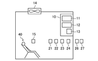
- the exemplary air conditioning system of this embodiment has the configuration schematically shown in FIG.
- the air conditioning system of the present embodiment includes an air conditioner (10) having a temperature control unit (11) for adjusting the temperature in the room and a humidity control unit (12) for adjusting the humidity in the room.
- the air conditioner (10) further controls the temperature control unit (11) and the humidity control unit (12) so that the indoor temperature approaches the target temperature and the indoor humidity approaches the target humidity (12). 13).
- the control unit (13) is configured to execute the first mode of changing the target temperature and the target humidity so as to suppress the decrease in the sensible temperature of the occupant (40).
- a controller (15) for operating the air conditioning system and a ventilation unit (14) for ventilating the air in the room.
- sensors that detect indoor environmental information
- an indoor temperature sensor (21) that detects temperature an indoor humidity sensor (22) that detects humidity, and a CO 2 concentration sensor (23) that detects carbon dioxide concentration.
- an activity sensor for detecting the amount of activity of the occupant (40) is provided.
- sensors for detecting outdoor environmental information an outdoor temperature sensor (26) for detecting temperature and an outdoor humidity sensor (27) for detecting humidity are provided.
- a sensor for detecting illuminance may be further provided.
- each of the above sensors is connected to the air conditioner (10) and its control unit (13) wirelessly or by wire.
- each sensor is shown individually in FIG. 1, some of the sensors may be combined as one unit. Further, at least one sensor may be combined with the controller (15), may be provided with the air conditioner (10), or may be provided with the ventilation unit (14).
- the temperature control unit (11) may use, for example, a heat pump type refrigerating apparatus that performs a vapor compression refrigerating cycle. That is, although not shown, a refrigerant circuit or the like in which the refrigerant circulates and performs a refrigeration cycle may be provided.
- the humidity control unit (12) may be configured to control the humidity in the room by using a solid hygroscopic agent (not shown). Further, the humidity in the room may be adjusted by absorbing moisture from the air in one of the indoor and outdoor areas and releasing it to the other. Further, the humidity control unit (12) is configured to individually use an ultrasonic type, an evaporation type, etc. humidifier and an adsorbent type, etc.
- dehumidifier instead of being provided in the air conditioner (10). There may be. Only one function of humidifying and dehumidifying the room is provided in the air conditioner (10), and the other can be provided as a separate device. When a humidifier / dehumidifier is used separately from the air conditioner (10), the humidifier / dehumidifier is also connected to the control unit (13) wirelessly or by wire.
- the ventilation unit (14) may be configured to include a ventilation fan provided in an opening such as a ceiling or a wall surface of the room, and if necessary, an air passage, a damper, or the like (not shown).
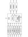
- FIG. 2 is a block diagram showing a control unit (13) in the air conditioning system of the present embodiment and components related thereto.
- the indoor temperature sensor (21), the indoor humidity sensor (22), the CO 2 concentration sensor (23), the activity sensor (24), the outdoor temperature sensor (26) and the outdoor Detected values and the like are input from the humidity sensor (27).
- a signal for operating the air conditioning system is input from the controller (15).
- the control unit (13) which will be described in detail later, includes an estimation unit (31) and a storage unit (32) that stores model information (33).
- the control unit (13) is based on the input from each of the above sensors and the controller (15), and uses the model information (33) stored in the estimation unit (31) and the storage unit (32) to obtain the temperature. It controls the control unit (11), humidity control unit (12) and ventilation unit (14). Further, as will be described later, the control unit (13) may be connected to an external server to send and receive information related to the control of the air conditioning system.
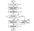
- FIG. 3 is a flowchart showing an example of an operation method
- FIG. 4 is a diagram showing an example of control contents by an air conditioning system.
- the first mode is an operation mode that suppresses a decrease in the sensible temperature of the occupant (40).
- the contents of this mode and the operations performed in each of the following steps will be described in detail later.
- step S1 the first mode is started. This may be started by the occupant (40) instructing the start using the controller (15). Further, the activity sensor (24) may detect the activity state of the occupant (40), and the activity may be started when the activity amount of the occupant (40) is small. When the user returns home and enters the room, it may start after taking a bath.
- each sensor is used to detect indoor environmental conditions.
- the indoor temperature sensor (21) and the indoor humidity sensor (22) are used to detect the indoor temperature and humidity.
- step S3 the target temperature is set for the indoor temperature. This is the target temperature for the control unit (13) to control and approach the temperature control unit (11), and is determined in consideration of the comfort of the occupant (40).
- step S4 it is determined whether or not the indoor humidity satisfies a predetermined condition.
- the conditions will also be determined in consideration of the comfort of the occupants (40).
- step S4 If it is determined in step S4 that the humidity condition is satisfied, the process proceeds to step 6 and the indoor humidity is set as the target humidity.
- step 7 After setting the target humidity in step 5 or step 6, the process proceeds to step 7 to control the environmental conditions including the room temperature and the room humidity.
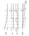
- control is generally performed to maintain a set temperature (air temperature). This is based on the assumption that if a temperature comfortable for the occupants is set, the comfortable state for the occupants will be maintained by maintaining the temperature.
- the target temperature (43) for constant temperature control and the target humidity (45) for constant temperature control are both shown as constant values without change.
- the metabolic rate (41) indicates the metabolic rate of a relaxed (for example, quietly sitting on a chair) occupant (40).
- the horizontal axis is time, and even if the person is similarly relaxed, the metabolic amount is 1.1 met (metabolic equivalent) at the beginning (at 0 minutes).
- the metabolic rate gradually decreases when the relaxed state is continued, and reaches 1.0 met after about 90 minutes. Due to such a decrease in the amount of metabolism, the sensible temperature decreases. It should be noted that the above-mentioned decrease in the metabolic amount occurs within about 90 minutes after the average state of relaxation, and the same degree of metabolic amount is maintained thereafter.
- Fig. 4 also shows the sensible temperature.
- the sensible temperature when the room temperature is maintained at the initial value Tn ° C of the set temperature is shown by a broken line as the sensible temperature (47) of constant temperature control. Even if the room temperature is maintained at Tn ° C., the sensible temperature (47) of constant temperature control decreases as the amount of metabolism decreases.
- control unit (13) performs a first operation of raising the target humidity in one step or multiple steps while maintaining the target temperature, and a second operation of raising the target temperature and lowering the target humidity. Execute at least once in order.
- the control unit (13) of the air conditioning system controls the temperature control unit (11) and the humidity control unit (12) to set the sensible temperature of the occupant (40) to a constant value. Maintain at (initial value Tn).
- Tn initial value
- the temperature in the room should be raised in accordance with the decrease in the amount of metabolism.
- the decrease in the sensible temperature is gradual, and even if the set temperature is increased in the smallest adjustable unit (for example, 0.5 ° C.), the occupant may feel the temperature increase. As a result, the occupant (40) may feel stressed or change the temperature setting of the air conditioning system.
- the sensible temperature can be adjusted in smaller units so that the change is not perceived. An example thereof is shown in FIG.
- the metabolic rate (41) gradually begins to decrease, and the sensible temperature begins to decrease accordingly (at this point, the same as the sensible temperature (47) of the constant temperature system). .. Therefore, after a certain period of time (15 minutes in the example of FIG. 4) elapses, the target humidity is increased to RHn + ( ⁇ / 2)% as in the first mode target humidity (44). As the humidity rises, the sensible temperature rises. As a result, the sensible temperature of the occupant (40) can be brought close to the target sensible temperature (46) that is maintained constant. Actually, the sensible temperature decreases until 15 minutes, similar to the sensible temperature (47) of the constant temperature system, and rises to the target sensible temperature (46) as the first mode target humidity (44) rises. Should be. However, if the decrease in the sensible temperature at 15 minutes is sufficiently small, it is not perceived by the occupant (40) and can be considered to be equivalent to achieving the target sensible temperature (46).
- the amount of increase in the target humidity (44) in the first mode is set to be equal to or more than the minimum unit that can be set as the target humidity.
- ⁇ / 2 may be 5% ( ⁇ may be 10%).
- the metabolic rate (41) will continue to decrease and the sensible temperature will continue to decrease. Therefore, when a certain time has elapsed (30 minutes in FIG. 4), the first mode target humidity (44) is raised again to RHn + ⁇ %. As a result, the sensible temperature of the occupant (40) is maintained close to the target sensible temperature (46).
- the operation of raising the first mode target humidity in one step or multiple steps while maintaining the first mode target temperature (42) is defined as the first operation.
- the metabolic rate (41) will continue to decrease until about 90 minutes have passed. Therefore, the target temperature and the target humidity are continuously controlled to maintain the sensible temperature of the occupant (40). However, if the humidity continues to rise, high humidity can cause discomfort. Therefore, at a certain time point (45 minutes in FIG. 4), the first mode target temperature (42) is raised (Tn + ⁇ ° C.) and the first mode target humidity (44) is lowered (FIG. 4). In the example of, return to RHn%). As a result, the sensible temperature of the occupant (40) can be maintained close to the target sensible temperature (46) while keeping the humidity within a certain range. This operation is referred to as a second operation.
- the amount of increase in the target temperature should be equal to or greater than the minimum unit that can be set as the target temperature. For example, if the air conditioning system can adjust the temperature in 0.5 ° C increments, ⁇ may be 0.5 ° C.
- the first mode target humidity (44) and the first mode target temperature (42) are similarly controlled to keep the sensible temperature of the occupant (40) constant. maintain.
- the decrease in the metabolic rate (41) is completed and the decrease in the sensible temperature does not occur. Therefore, the first mode is completed in about 90 minutes, and by maintaining the temperature and humidity at that time, the sensible temperature of the occupant (40) can be maintained without fluctuating.
- the temperature rises by ⁇ ° C. and the humidity rises by ⁇ % from the time when the first mode is started. If the values of ⁇ and ⁇ are as in the above example, the temperature has risen by 0.5 ° C. and the humidity has risen by 10%.
- the temperature is raised only once. However, it may be performed multiple times. In this case, the first operation of raising the target humidity in one step or multiple steps while maintaining the target temperature and the second operation of raising the target temperature and lowering the target humidity are repeated in order.
- Humidity is raised by ⁇ / 2 ° C in two steps, but this can also be simplified by step by step, and conversely, it can be raised in three or more steps.
- control is performed with 15 minutes as the time unit, but this is an example, and other time units may be used. It is not essential to control every same time unit, and the interval of control may be gradually widened in consideration of the gradual decrease in the metabolic rate (41).
- the time for continuing the first mode is about 90 minutes. This is because it takes about 90 minutes on average to complete the decrease in human metabolism in a relaxed state.
- a slightly longer or shorter time (for example, about 75 to 115 minutes) may be set in consideration of individual differences and the like.
- the target temperature and humidity it is possible to set the target temperature and humidity to the temperature and humidity set by the occupant (40) using the controller (15) or the like.
- the controller (15) or the like since the occupant (40) cannot always set an appropriate value, it is desirable to automatically set a comfortable target temperature and target humidity.
- the control unit (13) of the air conditioning system is an estimation unit (31) that estimates the room temperature (comfortable temperature) that the occupant (40) feels comfortable with, and makes such an estimation. It is provided with a storage unit (32) that stores model information (33) to be used. Indoor and outdoor environmental information (particularly temperature and humidity) is input from each sensor to the control unit (13), and the estimation unit is based on the information and the model information (33) of the storage unit (32). (31) estimates the comfortable temperature. This is a temperature that the occupant (40) does not feel hot or cold, and is also called a thermal neutral temperature.
- Model information (33) includes, for example, Adaptive Comfort Model. This is a model that identifies the thermal neutral temperature in a room based on the history of outdoor temperatures experienced by humans.
- the estimation unit (31) may set the target temperature in the room based on the information of such a model stored in the storage unit (32) and the information of the outdoor temperature obtained by the outdoor temperature sensor (26). Of course, it is also possible to set the target temperature based on other types of information. Further, as will be described later, the air conditioning system may be connected to the server via the Internet or the like, and the estimated target temperature may be set there. Artificial intelligence may be used for this.
- the target humidity is based on conditions such as ensuring that the skin moisture content of the occupant (40) is within an appropriate range and that it is below a predetermined upper limit that can suppress the growth of mold in the room. Will be decided.
- the target humidity is preferably set to an absolute humidity of 21 g / kg or less, and more preferably set to 18 g / kg or less.
- the target humidity is preferably set to an upper limit value or less that can suppress the generation of mold, for example, 60% or less.
- FIG. 5 shows the correspondence of absolute humidity (g / kg) corresponding to relative humidity (horizontal axis,%) and temperature (vertical axis, ° C.). Further, when the above conditions (1) and (2) are satisfied, the cell range of the table is surrounded by a thick line and the numerical value is shown in bold. When the target temperature is set, the target humidity is set from this range.
- the indoor temperature by the indoor temperature sensor (21) is 22 ° C. and the relative humidity in the room by the indoor humidity sensor (22) is 35%.
- the absolute humidity in the room is 6.8 g / kg, which does not satisfy the condition (2) above.
- the temperature is comfortable at 22 ° C, avoid changing the temperature and select the humidity to satisfy the condition (2). Also, from the viewpoint of energy saving, the amount of fluctuation should be minimized.
- the absolute humidity becomes 8.7 g / kg, and the condition (2) is satisfied. Therefore, the environment is controlled by setting the initial target temperature to 22 ° C. and the initial target humidity to 45%.
- this is just an example, and other methods may be used to determine the target humidity.
- the room temperature detected by the room temperature sensor (21) is not a comfortable temperature, set the target temperature using, for example, model information (33) as described above.
- a desirable target humidity is determined, for example, as shown in FIG.
- the operation of the first mode corresponding to the decrease in the metabolic rate (41) as shown in FIG. 4 may be performed after the target temperature is achieved by the temperature control unit (11).
- the first mode may be started by the operation of the occupant (40) (using the controller (15)). On the other hand, it is also preferable to detect that the occupant (40) is relaxed and start automatically.
- the activity sensor (24) is used to detect the amount of activity of the occupants (40).
- the activity sensor (24) is, for example, an infrared sensor, an image pickup device, or the like.
- the control unit (13) starts the first mode. In this way, it is possible to control the temperature in response to the decrease in the sensible temperature without the need for the occupant (40) to operate the room. For example, it is particularly effective when the resident (40) falls asleep.
- the air conditioning system of this embodiment has been described as being controlled by an independent control unit (13).
- the air conditioning system may be connected to an external server.
- the functions corresponding to the estimation unit (31) and the storage unit (32) are provided in the external server (both the control unit (13) and the external server may be provided).
- the external server may be a server installed in the same building as the air conditioning system for controlling a plurality of air conditioning systems, or a cloud server connected via the Internet.
- the air conditioner indoor unit (51) and the sensor unit (52) constituting the air conditioning system are shown.
- the air conditioner indoor unit (51) corresponds to the air conditioner (10) shown in FIG.
- the sensor unit (52) is a unit configured separately from the air conditioner indoor unit (51) including various sensors, and is used, for example, by being placed near a resident (40). Specifically, it has the functions of the indoor temperature sensor (21), indoor humidity sensor (22), and CO 2 concentration sensor (23) shown in FIG. 1, and further, the activity sensor (24) and the illuminance for detecting the indoor brightness. It may also have a function such as a sensor. Further, for example, the function of the controller (15) may be provided so as to enable operation by voice.
- the sensor unit (52) detects (measures) indoor temperature, humidity, carbon dioxide concentration, illuminance, etc., and inputs parameters including at least one of these environmental information to a sensor connection server (53) connected via the Internet or the like. ). Further, the parameters related to the feeling of warmth and coldness of the occupant (40) may be similarly transmitted to the sensor connection server (53).
- the parameters related to the feeling of warmth and coldness are, for example, gender, age, weight, and the like, and are matters that affect the feeling of heat and cold.
- the preference of the occupant (40) regarding heat and cold (such as heat) may be included as a parameter.
- the sensor connection server (53) has the function of artificial intelligence (55). Based on the information and parameters transmitted from the sensor unit (52), a learning model is generated in the sensor connection server (53) to determine the comfortable temperature. The determined comfortable temperature information is transmitted to another remote server (54). The remote server (54) transmits the comfortable temperature and the like received from the sensor connection server (53) to the air conditioner indoor unit (51) via the Internet or the like. The air conditioner indoor unit (51) adjusts the indoor temperature based on the received comfortable temperature.
- FIG. 7 shows yet another example.
- the air conditioning system includes the air conditioner indoor unit (51) and the sensor unit (52) as in the example of FIG. 6, and the configurations and functions of each are also the same.
- the sensor connection server (53) is not used, and the sensor unit (52) directly transmits the detected information such as the room temperature to the remote server (54).
- the function of the artificial intelligence (55) is provided in the remote server (54), and the artificial intelligence (55) determines the comfortable temperature in the remote server (54).
- the determined comfortable temperature is transmitted from the remote server (54) to the air conditioner indoor unit (51), and the indoor temperature is adjusted based on this.
- the artificial intelligence (55) can be used by the control unit (13) without using an external server.
- the air conditioning system of the present embodiment may include a CO 2 concentration sensor (23) and a ventilation unit (14).
- the carbon dioxide concentration is one of the indexes for evaluating the indoor air quality, and it is desirable to keep it below a predetermined value. Therefore, if the CO 2 concentration sensor (23) detects the carbon dioxide concentration in the room and the concentration exceeds a predetermined value, the control unit (13) operates the ventilation unit (14) to ventilate the room. To do.
- the ventilation unit (14) may be operated when the carbon dioxide concentration reaches 1000 ppm or more according to a guideline set as an environmental management standard for buildings. If it is particularly necessary, a sensor for detecting the concentration of other gases of carbon dioxide may be used to maintain the concentration below a predetermined value.
- Temperature control unit 12 Humidity control unit 13 Control unit 14 Ventilation unit 15 Controller 21 Indoor temperature sensor 22 Indoor humidity sensor 23 CO 2 concentration sensor (carbon dioxide concentration detection unit) 24 Activity sensor (activity detection unit) 26 Outdoor temperature sensor (outside air temperature detector) 27 Outdoor humidity sensor 31 Estimator 32 Storage 33 Model information (related information) 40 residents 51 Air conditioner indoor unit 52 Sensor unit 53 Sensor connection server 54 Remote server 55 Artificial intelligence
Landscapes
- Engineering & Computer Science (AREA)
- Signal Processing (AREA)
- Chemical & Material Sciences (AREA)
- Combustion & Propulsion (AREA)
- Mechanical Engineering (AREA)
- General Engineering & Computer Science (AREA)
- Physics & Mathematics (AREA)
- Fuzzy Systems (AREA)
- Mathematical Physics (AREA)
- Air Conditioning Control Device (AREA)
- Ventilation (AREA)
Abstract
空調システムは、室内の温度を調節する温度調節部(11)と、室内の湿度を調節する湿度調節部(12)と、室内の温度を目標温度に近づけ、且つ室内の湿度を目標湿度に近づけるように温度調節部及び湿度調節部を制御する制御部(13)とを備える。制御部(13)は、在室者(40)の体感温度の低下を抑制するように、目標温度及び目標湿度を変化させる第1モードを実行するように構成される。
Description
本開示は、空調システムに関する。
空気調和機において、空気の温度と湿度とを独立して調節し、快適性の向上を図ることが知られている。例えば特許文献1には、放熱空気と吸熱空気との熱交換を行う熱交換器、放熱空気から吸湿して吸熱空気に放湿する湿度媒体、湿度媒体を再生する除湿手段、及び、除湿手段で湿度媒体を再生するための熱を供給する熱供給手段を備える空気調和装置が開示されている。
従来の空気調和装置による空調では、室内の温度、湿度等を一定に維持していたとしても、空調対象である室内のユーザーが快適性の低下を感じる場合があった。
本開示の目的は、快適性の更なる維持が可能な空調システムを提供することである。
本開示の第1の態様は、室内の温度を調節する温度調節部(11)と、室内の湿度を調節する湿度調節部(12)と、室内の温度を目標温度に近づけ、且つ室内の湿度を目標湿度に近づけるように温度調節部(11)及び湿度調節部(12)を制御する制御部(13)とを備える空調システムを対象とし、制御部(13)は、在室者(40)の体感温度の低下を抑制するように、目標温度及び目標湿度を変化させる第1モードを実行するように構成される。
第1の様態では、在室者(40)の体感温度を考慮して目標温度及び目標湿度を制御するので、更に快適性を維持することができる。
本開示の第2の態様は、上記第1の態様において、制御部(13)は、第1モードにおいて、目標温度を維持しながら目標湿度を1段階又は多段階に上昇させる第1動作と、目標温度を上昇させ且つ目標湿度を低下させる第2動作とを順に少なくとも1回ずつ実行させるものである。
第2の態様では、目標温度及び目標湿度の両方を変化させることにより、目標温度のみを変化させる等の場合よりも、より精密に在室者(40)の体感温度を維持することができる。
本開示の第3の態様は、上記第1又は2の態様において、第1モードの開始時の目標湿度は、在室者(40)の肌水分率が適切な範囲になるように決定された所定の範囲に設定されるものである。
第3の態様では、在室者が肌の痒み、べたつき等を感じることを抑制できる。
本開示の第4態様は、上記第1~3のいずれか1つの態様において、第1モードの開始時の目標湿度は、カビの発生を抑制できる所定の上限値以下に設定されるものである。
第4の態様では、室内におけるカビの発生を抑制できる。
本開示の第5の態様は、上記第1~4のいずれか1つの態様において、制御部(13)は、在室者(40)が快適と感じる室内の快適温度を推定する推定部を有し、目標温度は、推定部(31)によって推定される快適温度であるものである。
第5の態様では、在室者(40)にとっての快適な室温を推定して制御することができる。
本開示の第6の態様は、上記第5の態様において、外気温度を検出する外気温度検出部(26)と、快適温度と外気温度との関係を示す関係情報を記憶した記憶部(32)と、を備え、制御部(13)は、記憶部(32)に記憶された関係情報(33)を用い、外気温度検出部(26)により検出される外気温度に基づいて快適温度を推定するものである。
第6の態様では、外気温度及び関係情報(33)を利用して目標温度を設定することができる。
本開示の第7の態様は、上記第5の態様において、推定部(31)は、室内の温度、室内の湿度、室内の照度、室外の温度及び室外の湿度の少なくとも1つを含む環境情報に関するパラメータと、在室者(40)の温冷感に関するパラメータとに基づいて生成された学習モデルにより、快適温度を推定するものである。
第7の態様では、学習モデルを利用して目標温度を設定することができる。
本開示の第8の態様は、上記第1~第7のいずれかひとつの態様において、室内空気を換気する換気部(14)と、室内の二酸化炭素濃度を検出する二酸化炭素濃度検出部(23)と、を備え、制御部(13)は、前記二酸化炭素濃度検出部により検出される二酸化炭素濃度が所定値以上になったときに、換気部(14)を運転するものである。
第8の態様では、室内の二酸化炭素濃度を制御することができる。
本開示の第9の態様は、上記第1~第8のいずれかひとつの態様において、第1モードを開始する機能を有するコントローラ(15)を備えるものである。
第9の態様では、第1モードを開始するために、コントローラ(15)を利用することができる。
本開示の第10の態様は、上記第1~第9のいずれかひとつの態様において、室内における在室者(40)の活動量を検出する活動検出部(24)を備え、活動検出部(24)により、室内における在室者(40)の活動量が所定値以下であることが検出された場合に、制御部(13)が第1モードを開始するものである。
第10の態様では、第1モードの開始が望ましいと判断される状況において、第1モードを自動的に開始することができる。
本開示の第11の態様は、上記第1~第9のいずれかひとつの態様において、室内における在室者(40)の活動量を検出する活動検出部(24)を備え、第1モードを実行中に、活動検出部(24)により、室内における在室者(40)の活動量が所定値以上であることが検出された場合に、制御部(13)が第1モードを停止するものである。
第11の態様では、第1モードの停止が望ましいと判断される状況において、第1モードを自動的に停止することができる。
本開示の実施形態について、図面を参照して説明する。本実施形態の例示的空調システムは、図1に模式的に示す構成を有する。
-空調システムの構成-
図1に示す通り、本実施形態の空調システムは、室内の温度を調節する温度調節部(11)及び室内の湿度を調節する湿度調節部(12)を有する空気調和機(10)を含む。空気調和機(10)は、更に、室内の温度を目標温度に近づけ、且つ、室内の湿度を目標湿度に近づけるように温度調節部(11)及び湿度調節部(12)を制御する制御部(13)を有する。制御部(13)は、在室者(40)の体感温度の低下を抑制するように、目標温度及び目標湿度を変化させる第1モードを実行するように構成される。
図1に示す通り、本実施形態の空調システムは、室内の温度を調節する温度調節部(11)及び室内の湿度を調節する湿度調節部(12)を有する空気調和機(10)を含む。空気調和機(10)は、更に、室内の温度を目標温度に近づけ、且つ、室内の湿度を目標湿度に近づけるように温度調節部(11)及び湿度調節部(12)を制御する制御部(13)を有する。制御部(13)は、在室者(40)の体感温度の低下を抑制するように、目標温度及び目標湿度を変化させる第1モードを実行するように構成される。
更に、空調システムを操作するためのコントローラ(15)と、室内の空気を換気するための換気部(14)とが備えられている。
また、室内の環境情報を検出するセンサ(検出部)として、温度を検出する室内温度センサ(21)、湿度を検出する室内湿度センサ(22)、二酸化炭素濃度を検出するCO2濃度センサ(23)が備えられている。更に、在室者(40)の活動量を検出する活動センサ(24)が備えられる。また、室外の環境情報を検出するセンサとして、温度を検出する室外温度センサ(26)と、湿度を検出する室外湿度センサ(27)が備えられる。図示はしないが、以上の他の環境情報、例えば照度を検出するセンサが更に備えられていても良い。
上記の各センサ(21,22,23,24,26及び27)は、図示はしていないが、無線又は有線により空気調和機(10)、ひいてはその制御部(13)と接続されている。図1では各センサが個別に示されているが、そのうちの幾つかのセンサが1つのユニットとして組み合わせられていても良い。更に、少なくとも一つのセンサは、コントローラ(15)に組み合わせられていても良いし、空気調和機(10)に備えられていても良いし、換気部(14)に備えられていても良い。
温度調節部(11)は、例えば、蒸気圧縮式の冷凍サイクルを行うヒートポンプ式の冷凍装置を利用していても良い。つまり、図示はしないが、冷媒が循環して冷凍サイクルを行う冷媒回路等を備えていても良い。湿度調節部(12)は、固体吸湿剤(図示せず)を用いて室内の湿度を調節する構成であっても良い。また、室内及び室外の一方にて空気から水分を吸収し、他方に放出することにより室内の湿度を調節する構成であっても良い。更に、湿度調節部(12)は、空気調和機(10)に備えられることに代えて、個別に超音波式、蒸発式等の加湿器と、吸着剤式等の除湿器とを用いる構成であっても良い。室内の加湿、除湿の一方の機能のみが空気調和機(10)に備えられ、他方は個別の機器として設けることもできる。空気調和機(10)とは別に加湿器/除湿器を用いる場合、当該加湿器/除湿器についても制御部(13)と無線又は有線により接続される。
換気部(14)は、部屋の天井、壁面等の開口部に設けられた換気ファンと、必要に応じて空気通路、ダンパ等(図示せず)を備える構成であっても良い。
次に、図2は、本実施形態の空調システムにおける制御部(13)及びこれに関連する構成要素を示すブロック図である。図2に示す通り、制御部(13)に対し、室内温度センサ(21)、室内湿度センサ(22)、CO2濃度センサ(23)、活動センサ(24)、室外温度センサ(26)及び室外湿度センサ(27)から、それぞれ検出値等が入力される。また、コントローラ(15)から、空調システムを操作する信号が入力される。
制御部(13)は、後に詳しく説明するが、推定部(31)、モデル情報(33)を記憶した記憶部(32)を備える。制御部(13)は、上記の各センサ及びコントローラ(15)からの入力に基づき、且つ、推定部(31)及び記憶部(32)に記憶されたモデル情報(33)を利用して、温度調節部(11)、湿度調節部(12)及び換気部(14)を制御する。更に、後述するが、制御部(13)を外部のサーバと接続し、空調システムの制御に関する情報等を送受信するようにしてもよい。
―空調システムの動作方法―
次に、本実施形態の空調システムの動作方法について説明する。図3は、動作方法の一例を示すフローチャートであり、図4は、空調システムによる制御内容等の一例を示す図である。
次に、本実施形態の空調システムの動作方法について説明する。図3は、動作方法の一例を示すフローチャートであり、図4は、空調システムによる制御内容等の一例を示す図である。
まず、図3のフローチャートを参照して、空調システムの第1モードの動作について説明する。第1モードは、在室者(40)の体感温度の低下を抑制する動作モードである。このモードの内容及び以下の各ステップで行う動作について、いずれも詳しくは後述する。
ステップS1では、第1モードが開始される。これは、在室者(40)がコントローラ(15)を用いて開始を指示することにより開始されても良い。また、活動センサ(24)により在室者(40)の活動状態を検出し、在室者(40)の活動量が小さい場合に開始されても良い。ユーザーが帰宅して部屋に入ってきたとき、風呂上がり等に開始するのであっても良い。
ステップS2では、各センサを用いて室内の環境条件を検出する。特に、室内温度センサ(21)及び室内湿度センサ(22)を用いて、室内の温度及び湿度を検出する。
ステップS3では、室内の温度について、目標温度を設定する。これは、制御部(13)が温度調節部(11)を制御して近づけるための目標となる温度であり、在室者(40)の快適性を考慮して決定される。
ステップS4では、室内湿度が所定の条件を満たしているかどうかを判断する。当該条件についても、在室者(40)の快適性等を考慮して決定される。
ステップS4で湿度に関する条件が満たされないと判断された場合、ステップ5に進み、条件を満たす目標湿度を設定する。
ステップS4で湿度に関する条件が満たされると判断された場合、ステップ6に進み、室内湿度を目標湿度として設定する。
ステップ5又はステップ6において目標湿度を設定した後、ステップ7に進み、室内温度及び室内湿度を含む環境条件の制御を行う。
―第1モードにおける温度及び湿度の制御―
次に、図3のステップ7に対応する環境制御に関して説明する。
次に、図3のステップ7に対応する環境制御に関して説明する。
ルームエアコン等の空気調和機において、一般的には、設定された温度(気温)を維持する制御が行われる。これは、在室者にとって快適な温度が設定されれば、その温度を維持することにより、在室者にとって快適な状態が維持するとの想定によるものである。図4において、このような定温制御の目標温度(43)及び定温制御の目標湿度(45)を、いずれも変化の無い一定値として示している。
しかしながら、在室者(40)の活動状態によっては、単純に同じ温度を維持するだけでは快適な状態を保てない場合がある。特に、在室者(40)の活動量が小さい場合、例えば、椅子に静かに座ってくつろいでいる場合等には、同じ温度が維持されていると、在室者(40)は寒さを感じ始めることがある。これは、人間は活動しない(体を動かさない)で居ると次第に代謝量が低下し、体の熱の発生が小さくなるので、同じ温度であっても体感温度が低くなることによる。
これに関し、図4において、代謝量(41)は、リラックスしている(例えば静かに椅子に腰掛けている)在室者(40)の代謝量を示す。横軸は時間であり、同じようにリラックスしていても、当初(0分の時点)は例えば代謝量が1.1met(metabolic equivalent)である。これに対し、リラックス状態を続けると次第に代謝量が低下し、90分程度経過した時点で1.0metになることを示す。このような代謝量の低下により、体感温度が低下する。尚、上記の代謝量の低下は、平均的にリラックス状態になってから90分程度の間に起こり、その後は同程度の代謝量が維持される。
図4に、体感温度についても示している。室内の温度を設定温度の初期値Tn℃に維持した場合の体感温度を、定温制御の体感温度(47)として破線により示す。室内の温度がTn℃に維持されていたとしても、代謝量の低下に伴い、定温制御の体感温度(47)は低下する。
このような体感温度の低下が発生すると、在室者(40)の快適性が低下し、ストレスを感じてリラックスが妨げられる。また、在室者(40)は、寒さを感じるのであるから、空調の設定温度を上げる動作を行うと考えられる。
そこで、本実施形態の空調システムは、在室者(40)の活動量が小さくリラックス状態にある場合に、在室者(40)の体感温度が低下しないように維持する第1モード(リラックスモード)を実行することができる。
制御部(13)は、第1モードにおいて、目標温度を維持しながら目標湿度を1段階又は多段階に上昇させる第1動作と、目標温度を上昇させ且つ目標湿度を低下させる第2動作とを順に少なくとも1回ずつ実行させる。
より具体的に、第1モードにおいて、空調システムの制御部(13)は、温度調節部(11)及び湿度調節部(12)を制御して、在室者(40)の体感温度を一定値(初期値Tn)に維持する。このためには、最も基本的には、代謝量の低下に合わせて室内の温度を高くすれば良い。但し、体感温度の低下は緩やかであり、調節可能な最小単位(例えば0.5℃)で設定温度を上げたとしても、在室者は温度の上昇を感じることがある。その結果、在室者(40)は、ストレスを感じたり、空調システムの温度設定を変えたりすることがある。
これに対し、温度に加えて湿度を調節することにより、より小さな単位で体感温度を調節して、その変化が知覚されないようにすることができる。その一例を図4に示す。
図4において、横軸が0分の時点で第1モードを開始したとする。この時点の室内において、温度(温度の初期値)がTn℃、湿度(湿度の初期値)がRHn%(相対湿度)であって、それぞれ制御の目標温度及び目標湿度でもある(在室者(40)にとって快適な状態で第1モードが開始された)とする。
在室者(40)がリラックスしていると、次第に代謝量(41)が低下し始め、これに伴って体感温度も低下し始める(この時点では、定温制度の体感温度(47)と同様)。そこで、一定時間(図4の例では15分)経過後、第1モード目標湿度(44)のように、目標湿度をRHn+(β/2)%に上昇させる。湿度が上昇すると、体感温度は上昇する。これにより、在室者(40)の体感温度を、一定に維持される目標体感温度(46)に近づけることができる。実際には、定温制度の体感温度(47)と同様に15分の時点までは体感温度が低下し、第1モード目標湿度(44)の上昇に伴って、目標体感温度(46)まで上昇するはずである。しかし、15分の時点における体感温度の低下が十分に小さければ、在室者(40)に知覚されず、目標体感温度(46)を達成しているのと同等と考えることができる。
尚、この際の第1モード目標湿度(44)の上昇量、つまりβ/2は、目標湿度として設定可能な最小単位以上とする。例えば、空調システムが相対湿度を5%単位で調節可能であれば、β/2を5%(βを10%)としてもよい。
15分経過した後も、在室者(40)がリラックス状態を維持していた場合、代謝量(41)の低下と、これに伴う体感温度の低下が続く。そこで、更に一定時間が経過した時点(図4では30分の時点)において、再度、第1モード目標湿度(44)を再度上昇させてRHn+β%とする。これにより、在室者(40)の体感温度は目標体感温度(46)に近い状態が維持される。
以上のように、第1モード目標温度(42)を維持しながら、第1モード目標湿度と1段階又は多段階に上昇させる動作を第1動作とする。
リラックス状態が続くと、90分程度が経過するまでの間、代謝量(41)は低下し続ける。従って、継続して目標温度及び目標湿度を制御し、在室者(40)の体感温度を維持する。しかし、湿度を上昇させ続けると、高い湿度が不快感の原因となり得る。そこで、ある時点(図4では45分の時点)において、第1モード目標温度(42)を上昇させる(Tn+α℃とする)と共に、第1モード目標湿度(44)を低下させる(図4の例では、RHn%に戻す)。これにより、湿度を一定の範囲に保ちながら、在室者(40)の体感温度を目標体感温度(46)に近い状態に維持することができる。この動作を第2動作とする。
尚、目標温度の上昇量、つまりαは、目標温度として設定可能な最小単位以上とする。例えば、空調システムが温度を0.5℃単位で調節可能であれば、αを0.5℃としてもよい。
この後、更にリラックス状態が続いているのであれば、同様に第1モード目標湿度(44)及び第1モード目標温度(42)を制御して、在室者(40)の体感温度を一定に維持する。90分程度が経過すると、代謝量(41)の低下が終了して体感温度の低下も発生しなくなる。従って、第1モードは90分程度で終了し、その時点での温度及び湿度を維持することで、在室者(40)の体感温度を変動させること無く維持することができる。このとき、図4の例では、第1モードを開始した時点よりも温度がα℃上昇し、湿度がβ%上昇している。α、βの値が上記の例の通りであれば、温度が0.5℃上昇し、湿度が10%上昇していることになる。
以上の例では、温度の上昇は1回だけ行っている。しかし、複数回行っても良い。この場合、目標温度を維持しながら目標湿度を1段階又は多段階に上昇させる第1動作と、目標温度を上昇させ且つ目標湿度を低下させる第2動作とを順に繰り返し行う。湿度の上昇はβ/2℃ずつ2段階にて行っているが、こちらも1段階ずつにして簡略化することもでき、逆に、3段階以上とすることもできる。
また、15分を時間単位として制御を行っているが、これは一例であり、他の時間単位でもよい。同じ時間単位毎に制御することも必須ではなく、代謝量(41)の低下が次第に緩やかになることを考慮して、制御の間隔も次第に広くしても良い。
また、以上の通り、第1モードを継続する時間は、90分程度とするのが望ましい。これは、リラックス状態において人間の代謝量の低下が終了するまでの平均的な時間が90分程度だからである。しかし、個人差等を考慮して、もう少し長い又は短い時間(例えば75分~115分程度)を設定しても良い。
―目標温度、目標湿度の決定方法―
次に、空調システムによる制御の目標温度及び目標湿度の決定方法に関して説明する。
次に、空調システムによる制御の目標温度及び目標湿度の決定方法に関して説明する。
まず、目標温度及び目標湿度について、在室者(40)がコントローラ(15)等を用いて設定した温度及び湿度とすることは可能である。しかしながら、在室者(40)が必ずしも適切な設定を行えるものではないので、自動的に快適な目標温度及び目標湿度が設定されることが望ましい。
そこで、図2に示すように、空調システムの制御部(13)は、在室者(40)が快適と感じる室内温度(快適温度)を推定する推定部(31)と、このような推定に利用するモデル情報(33)を記憶した記憶部(32)とを備える。制御部(13)には各センサから室内及び室外における環境情報(特に、温度及び湿度)が入力され、当該情報と、記憶部(32)をのモデル情報(33)とに基づいて、推定部(31)は快適温度を推定する。これは、在室者(40)が暑いとも寒いとも感じることのない温度であり、熱的中立温度とも呼ばれる。
モデル情報(33)としては、例えばAdaptive Comfort Modelがある。これは、人間が経験した室外温度の履歴に基づき、室内における熱的中立温度を特定するモデルである。記憶部(32)に記憶したこのようなモデルの情報と、室外温度センサ(26)により得た室外温度の情報に基づいて、推定部(31)が室内における目標温度を設定しても良い。他の種類の情報に基づいて目標温度を設定することも当然可能である。また、後に説明するが、空調システムがインターネット等を介してサーバに接続され、そこで推測された目標温度を設定するようにしても良い。これには、人工知能が用いられても良い。
次に、目標湿度については、在室者(40)の肌水分量が適切な範囲になるようにすること、室内におけるカビの発生を抑制できる所定の上限値以下にすること等の条件に基づいて決定される。
室内の湿度が低くなると、在室者(40)の肌が乾燥傾向となり、痒みを感じる、かさつく等の不快感の原因となる。これは、絶対湿度(乾燥空気の質量に対する水蒸気の質量の比)との相関が強く、個人差もあるが、例えば8g/kg以下の絶対湿度において発生する。従って、目標湿度は絶対湿度8g/kg以上に設定することが好ましく、9g/kg以上に設定することがより好ましい。
また、室内の湿度が高くなると、在室者(40)が肌にベタつきを感じる等の不快感の原因となる。これについては、例えば絶対湿度21g/kg以上になると発生しやすい。従って、目標湿度は絶対湿度21g/kg以下に設定することが好ましく、18g/kg以下に設定することがより好ましい。
更に、室内において湿度が高すぎると、カビが発生しやすくなる。これは、相対湿度との相関が強く、相対湿度60%を越えると顕著にカビが発生しやすくなる。従って、目標湿度について、カビの発生を抑制できる上限値以下に設定することが好ましく、例えば60%以下に設定する。
以上から、目標湿度について、次の(1)及び(2)を満たすことが好ましい。
(1)絶対湿度:8g/kg以上で且つ21g/kg以下
(2)相対湿度:60%以下
図3のフローチャートのステップS4において判断に用いる所定条件は、上記(1)及び(2)であっても良い。
(1)絶対湿度:8g/kg以上で且つ21g/kg以下
(2)相対湿度:60%以下
図3のフローチャートのステップS4において判断に用いる所定条件は、上記(1)及び(2)であっても良い。
以上のことについて、図5に示している。図5には、相対湿度(横軸、%)及び温度(縦軸、℃)に対応する絶対湿度(g/kg)の対応が示されている。また、上記(1)及び(2)の条件を満たす場合について、表のセル範囲を太線で囲い、数値を太字としている。目標温度が設定されたとき、目標湿度は、この範囲から設定される。
例えば、室内温度センサ(21)による室内温度が22℃、室内湿度センサ(22)による室内の相対湿度が35%であったとする。この場合、図5に示す通り、室内の絶対湿度は6.8g/kgであって、上記(2)の条件を満たしていない。
温度については22℃で快適であるとすると、温度を変更することは避け、湿度を選択することにより(2)の条件を満たすようにする。また、省エネ等の観点から、変動量は最小にする。図5によると、温度は22℃に維持して相対湿度を45%にすると、絶対湿度が8.7g/kgとなり、(2)の条件を満たすようになる。従って、初期の目標温度を22℃、初期の目標湿度を45%と設定して、環境制御を行う。但し、これは一例であって、目標湿度を決定するために他の方法を用いても良い。
室内温度センサ(21)により検出した室内温度が快適な温度ではない場合、前記のように例えばモデル情報(33)を利用して目標温度を設定する。当該目標温度に対して、例えば図5に示すように望ましい目標湿度を決定する。図4に示すような代謝量(41)の低下に対応する第1モードの運転は、温度調節部(11)により目標温度を達成した後に行っても良い。
(変形例)
―第1モードの開始及び停止に関する制御―
本実施形態の空調システムにおいて、第1モードは、在室者(40)の操作(コントローラ(15)を用いる)により開始しても良い。これに対し、在室者(40)がリラックスしていることを検出して、自動的に開始するようにすることも好ましい。
―第1モードの開始及び停止に関する制御―
本実施形態の空調システムにおいて、第1モードは、在室者(40)の操作(コントローラ(15)を用いる)により開始しても良い。これに対し、在室者(40)がリラックスしていることを検出して、自動的に開始するようにすることも好ましい。
このためには、活動センサ(24)を利用して、在室者(40)の活動量を検出する。活動センサ(24)は、例えば赤外線センサ、撮像装置等である。活動センサ(24)により、室内における在室者(40)の活動量が所定値以下であることが検出されると、制御部(13)が第1モードを開始する。このようにすると、在室者(40)が操作しなくても、体感温度の低下に対応した制御が可能となる。例えば、在室者(40)が居眠りした場合等には特に効果的である。
また、第1モードの実行中に、在室者(40)の活動量が上昇する場合がある。この場合、在室者(40)の代謝の低下は中断され、従って体感温度の低下も生じなくなる。このまま第1モードを続行すると、体感温度が上昇して、在室者(40)の快適性が低下する。従って、在室者(40)の活動量が所定値以上となった場合には、第1モードを停止することが好ましい。
第1モードを実行していないときに、在室者(40)の活動量が大きい場合には、第1モードの実行を禁止するようにしても良い。タイマー設定、人工知能による学習等により実行が予定されていたが、在室者(40)の活動量が大きくなった場合等がこれに該当する。
―外部サーバの利用―
以上では、本実施形態の空調システムは独立した制御部(13)により制御されるものとして説明した。しかしながら、空調システムが外部のサーバに接続される構成としても良い。この場合、推定部(31)及び記憶部(32)に該当する機能が、外部のサーバに備えられる(制御部(13)と外部サーバの両方に備えられていても良い)。これについて、図6及び図7に例示する。外部サーバとは、空調システムと同じ建築物に設置されて複数の空調システムを制御するためのサーバであっても良いし、インターネットを介して接続されたクラウドサーバであっても良い。
以上では、本実施形態の空調システムは独立した制御部(13)により制御されるものとして説明した。しかしながら、空調システムが外部のサーバに接続される構成としても良い。この場合、推定部(31)及び記憶部(32)に該当する機能が、外部のサーバに備えられる(制御部(13)と外部サーバの両方に備えられていても良い)。これについて、図6及び図7に例示する。外部サーバとは、空調システムと同じ建築物に設置されて複数の空調システムを制御するためのサーバであっても良いし、インターネットを介して接続されたクラウドサーバであっても良い。
図6において、空調システムを構成するエアコン室内機(51)及びセンサーユニット(52)が示されている。エアコン室内機(51)は、図1の空気調和機(10)に対応する。センサーユニット(52)は、各種センサを含むエアコン室内機(51)とは別体に構成されたユニットであり、例えば在室者(40)の近くに置いて用いられる。具体的に、図1の室内温度センサ(21)、室内湿度センサ(22)、CO2濃度センサ(23)の機能を有し、更に、活動センサ(24)、室内の明るさを検出する照度センサ等の機能も備えていても良い。また、例えば音声による操作を可能とする形で、コントローラ(15)の機能を備えていても良い。
センサーユニット(52)は、室内の温度、湿度、二酸化炭素濃度及び照度等を検出(測定)し、これらの環境情報の少なくとも一つを含むパラメータを、インターネット等を通じて接続されたセンサー接続サーバ(53)に伝達する。また、在室者(40)の温冷感に関するパラメータについても、同様にセンサー接続サーバ(53)に伝達されても良い。温冷感に関するパラメータとは、例えば性別、年齢、体重等であって、暑さ、寒さの体感に影響する事項である。暑さ、寒さに関する在室者(40)の好み(暑がりである等)をパラメータとして含んでも良い。
センサー接続サーバ(53)は、人工知能(55)の機能を有する。センサーユニット(52)から伝達された情報及びパラメータに基づき、センサー接続サーバ(53)において学習モデルが生成され、快適温度を判断する。判断された快適温度の情報は、別のリモートサーバ(54)に伝達される。リモートサーバ(54)は、センサー接続サーバ(53)から受け取った快適温度等をインターネット等を介してエアコン室内機(51)に伝達する。エアコン室内機(51)は、受け取った快適温度に基づいて、室内温度を調節する。
図7には、更に別の例を示す。図7の場合も、空調システムがエアコン室内機(51)及びセンサーユニット(52)を含むことは図6の例と同様であり、それぞれの構成、機能等も同様である。但し、図7の例では、センサー接続サーバ(53)は用いられず、センサーユニット(52)は、検出した室内温度等の情報を直接、リモートサーバ(54)に伝達する。人工知能(55)の機能はリモートサーバ(54)に備えられており、リモートサーバ(54)において、人工知能(55)が快適温度を判断する。判断された快適温度はリモートサーバ(54)からエアコン室内機(51)に伝達され、これに基づいて室内の温度が調節される。
尚、人工知能(55)の利用については、外部サーバを利用せず、制御部(13)において行うこともできる。
―二酸化炭素濃度の制御―
図1に示す通り、本実施形態の空調システムは、CO2濃度センサ(23)と、換気部(14)とを備えていても良い。
図1に示す通り、本実施形態の空調システムは、CO2濃度センサ(23)と、換気部(14)とを備えていても良い。
二酸化炭素濃度は、室内空気の質を評価する指標の一つであり、所定値未満に維持することが望ましい。従って、CO2濃度センサ(23)により室内の二酸化炭素濃度を検出して、これが所定値以上となった場合等には、制御部(13)が換気部(14)を動作させて室内を換気する。具体例として、建築物の環境管理基準として定められている目安に従い、二酸化炭素濃度が1000ppm以上となった場合に換気部(14)を動作させるようにしても良い。尚、特に必要な場合等には、二酸化炭素の他のガスに関しても濃度を検出するためのセンサを用い、所定値以下に維持するようにしても良い。
以上、実施形態および変形例を説明したが、特許請求の範囲の趣旨および範囲から逸脱することなく、形態や詳細の多様な変更が可能なことが理解されるであろう。また、以上の実施形態および変形例は、本開示の対象の機能を損なわない限り、適宜組み合わせたり、置換したりしてもよい。
本開示は、空調システムとして有用である。
11 温度調節部
12 湿度調節部
13 制御部
14 換気部
15 コントローラ
21 室内温度センサ
22 室内湿度センサ
23 CO2濃度センサ(二酸化炭素濃度検出部)
24 活動センサ(活動検出部)
26 室外温度センサ(外気温度検出部)
27 室外湿度センサ
31 推定部
32 記憶部
33 モデル情報(関係情報)
40 在室者
51 エアコン室内機
52 センサーユニット
53 センサー接続サーバ
54 リモートサーバ
55 人工知能
12 湿度調節部
13 制御部
14 換気部
15 コントローラ
21 室内温度センサ
22 室内湿度センサ
23 CO2濃度センサ(二酸化炭素濃度検出部)
24 活動センサ(活動検出部)
26 室外温度センサ(外気温度検出部)
27 室外湿度センサ
31 推定部
32 記憶部
33 モデル情報(関係情報)
40 在室者
51 エアコン室内機
52 センサーユニット
53 センサー接続サーバ
54 リモートサーバ
55 人工知能
Claims (11)
- 室内の温度を調節する温度調節部(11)と、
室内の湿度を調節する湿度調節部(12)と、
室内の温度を目標温度に近づけ、且つ室内の湿度を目標湿度に近づけるように前記温度調節部及び前記湿度調節部を制御する制御部(13)とを備え、
前記制御部(13)は、在室者(40)の体感温度の低下を抑制するように、前記目標温度及び前記目標湿度を変化させる第1モードを実行するように構成される
ことを特徴とする空調システム。 - 請求項1において、
前記制御部(13)は、前記第1モードにおいて、前記目標温度を維持しながら前記目標湿度を1段階又は多段階に上昇させる第1動作と、前記目標温度を上昇させ且つ前記目標湿度を低下させる第2動作とを順に少なくとも1回ずつ実行させる
ことを特徴とする空調システム。 - 請求項1又は2において、
前記第1モードの開始時の目標湿度は、在室者(40)の肌水分率が適切な範囲になるように決定された所定の範囲に設定される
ことを特徴とする空調システム。 - 請求項1~3のいずれか1つにおいて、
前記第1モードの開始時の目標湿度は、カビの発生を抑制できる所定の上限値以下に設定される
ことを特徴とする空調システム。 - 請求項1~4のいずれか1つにおいて、
前記制御部(13)は、在室者(40)が快適と感じる室内の快適温度を推定する推定部(31)を有し、
前記目標温度は、前記推定部(31)によって推定される前記快適温度である
ことを特徴とする空調システム。 - 請求項5において、
外気温度を検出する外気温度検出部(26)と、
前記快適温度と外気温度との関係を示す関係情報(33)を記憶した記憶部(32)と、を備え、
前記制御部(13)は、前記記憶部(32)に記憶された前記関係情報(33)を用い、前記外気温度検出部(26)により検出される外気温度に基づいて前記快適温度を推定する
ことを特徴とする空調システム。 - 請求項5において、
前記推定部(31)は、室内の温度、室内の湿度、室内の照度、室外の温度及び室外の湿度の少なくとも1つを含む環境情報に関するパラメータと、在室者の温冷感に関するパラメータとに基づいて生成された学習モデルにより、前記快適温度を推定する
ことを特徴とする空調システム。 - 請求項1~7のいずれか1つにおいて、
室内空気を換気する換気部(14)と、
室内の二酸化炭素濃度を検出する二酸化炭素濃度検出部(23)と、を備え、
前記制御部(13)は、前記二酸化炭素濃度検出部(23)により検出される二酸化炭素濃度が所定値以上になったときに、前記換気部(14)を運転する
ことを特徴とする空調システム。 - 請求項1~8のいずれか1つにおいて、
前記第1モードを開始する機能を有するコントローラ(15)を備える
ことを特徴とする空調システム。 - 請求項1~9のいずれか1つにおいて、
前記室内における在室者(40)の活動量を検出する活動検出部(24)を備え、
前記活動検出部(24)により、前記室内における在室者(40)の活動量が所定値以下であることが検出された場合に、前記制御部(13)が前記第1モードを開始する
ことを特徴とする空調システム。 - 請求項1~9のいずれか1つにおいて、
前記室内における在室者(40)の活動量を検出する活動検出部(24)を備え、
前記第1モードを実行中に、前記活動検出部(24)により、前記室内における在室者(40)の活動量が所定値以上であることが検出された場合に、前記制御部(13)が前記第1モードを停止する
ことを特徴とする空調システム。
Priority Applications (4)
| Application Number | Priority Date | Filing Date | Title |
|---|---|---|---|
| EP20794250.9A EP3933285B1 (en) | 2019-04-22 | 2020-04-03 | Air conditioning system |
| SG11202110604TA SG11202110604TA (en) | 2019-04-22 | 2020-04-03 | Air-conditioning system |
| CN202080028362.5A CN113677937B (zh) | 2019-04-22 | 2020-04-03 | 空调系统 |
| US17/500,476 US20220042710A1 (en) | 2019-04-22 | 2021-10-13 | Air-conditioning system |
Applications Claiming Priority (2)
| Application Number | Priority Date | Filing Date | Title |
|---|---|---|---|
| JP2019081085A JP7460876B2 (ja) | 2019-04-22 | 2019-04-22 | 空調システム |
| JP2019-081085 | 2019-04-22 |
Related Child Applications (1)
| Application Number | Title | Priority Date | Filing Date |
|---|---|---|---|
| US17/500,476 Continuation US20220042710A1 (en) | 2019-04-22 | 2021-10-13 | Air-conditioning system |
Publications (1)
| Publication Number | Publication Date |
|---|---|
| WO2020217933A1 true WO2020217933A1 (ja) | 2020-10-29 |
Family
ID=72936267
Family Applications (1)
| Application Number | Title | Priority Date | Filing Date |
|---|---|---|---|
| PCT/JP2020/015361 WO2020217933A1 (ja) | 2019-04-22 | 2020-04-03 | 空調システム |
Country Status (6)
| Country | Link |
|---|---|
| US (1) | US20220042710A1 (ja) |
| EP (1) | EP3933285B1 (ja) |
| JP (1) | JP7460876B2 (ja) |
| CN (1) | CN113677937B (ja) |
| SG (1) | SG11202110604TA (ja) |
| WO (1) | WO2020217933A1 (ja) |
Families Citing this family (2)
| Publication number | Priority date | Publication date | Assignee | Title |
|---|---|---|---|---|
| CN113310191A (zh) * | 2021-06-09 | 2021-08-27 | 海信(山东)空调有限公司 | 空调器的控制方法及装置、空调器和计算机可读存储介质 |
| JP7249068B1 (ja) * | 2022-03-28 | 2023-03-30 | cynaps株式会社 | 換気制御システム |
Citations (6)
| Publication number | Priority date | Publication date | Assignee | Title |
|---|---|---|---|---|
| JPH074717A (ja) * | 1993-06-18 | 1995-01-10 | Kubota Corp | 空調装置 |
| JP2000320864A (ja) | 1999-05-13 | 2000-11-24 | Daikin Ind Ltd | 空気調和装置 |
| JP2003185217A (ja) * | 2001-12-19 | 2003-07-03 | Daikin Ind Ltd | 空気調和機 |
| JP2008121972A (ja) * | 2006-11-10 | 2008-05-29 | Daikin Ind Ltd | 空気調和機ならびに室内の湿度制御方法 |
| WO2009096350A1 (ja) * | 2008-01-28 | 2009-08-06 | Kabushiki Kaisha Toshiba | 空調制御システム |
| WO2014125805A1 (ja) * | 2013-02-13 | 2014-08-21 | パナソニック株式会社 | 指示装置、空気調和システム |
Family Cites Families (8)
| Publication number | Priority date | Publication date | Assignee | Title |
|---|---|---|---|---|
| US5259553A (en) * | 1991-04-05 | 1993-11-09 | Norm Pacific Automation Corp. | Interior atmosphere control system |
| JP3262288B2 (ja) * | 1992-08-26 | 2002-03-04 | 東芝キヤリア株式会社 | 空気調和機の湿度制御装置 |
| JP5258816B2 (ja) * | 2010-02-27 | 2013-08-07 | 三菱電機株式会社 | 空気調和機 |
| JP5544580B1 (ja) * | 2013-07-26 | 2014-07-09 | 株式会社 エコファクトリー | 空気調和装置及び空気調和装置の運転方法 |
| JP6334299B2 (ja) | 2014-07-04 | 2018-05-30 | 株式会社東芝 | 空調制御装置、空調制御方法、及びプログラム |
| JP2016061446A (ja) * | 2014-09-12 | 2016-04-25 | 日立アプライアンス株式会社 | 空気調和機 |
| JP6859068B2 (ja) | 2016-10-21 | 2021-04-14 | 東芝キヤリア株式会社 | 空気調和機の制御方法、空気調和機 |
| JP6946739B2 (ja) | 2017-05-19 | 2021-10-06 | ダイキン工業株式会社 | 空調システム |
-
2019
- 2019-04-22 JP JP2019081085A patent/JP7460876B2/ja active Active
-
2020
- 2020-04-03 CN CN202080028362.5A patent/CN113677937B/zh active Active
- 2020-04-03 WO PCT/JP2020/015361 patent/WO2020217933A1/ja unknown
- 2020-04-03 EP EP20794250.9A patent/EP3933285B1/en active Active
- 2020-04-03 SG SG11202110604TA patent/SG11202110604TA/en unknown
-
2021
- 2021-10-13 US US17/500,476 patent/US20220042710A1/en active Pending
Patent Citations (6)
| Publication number | Priority date | Publication date | Assignee | Title |
|---|---|---|---|---|
| JPH074717A (ja) * | 1993-06-18 | 1995-01-10 | Kubota Corp | 空調装置 |
| JP2000320864A (ja) | 1999-05-13 | 2000-11-24 | Daikin Ind Ltd | 空気調和装置 |
| JP2003185217A (ja) * | 2001-12-19 | 2003-07-03 | Daikin Ind Ltd | 空気調和機 |
| JP2008121972A (ja) * | 2006-11-10 | 2008-05-29 | Daikin Ind Ltd | 空気調和機ならびに室内の湿度制御方法 |
| WO2009096350A1 (ja) * | 2008-01-28 | 2009-08-06 | Kabushiki Kaisha Toshiba | 空調制御システム |
| WO2014125805A1 (ja) * | 2013-02-13 | 2014-08-21 | パナソニック株式会社 | 指示装置、空気調和システム |
Non-Patent Citations (1)
| Title |
|---|
| See also references of EP3933285A4 |
Also Published As
| Publication number | Publication date |
|---|---|
| JP2020176799A (ja) | 2020-10-29 |
| EP3933285B1 (en) | 2024-05-22 |
| CN113677937A (zh) | 2021-11-19 |
| EP3933285A4 (en) | 2022-12-07 |
| CN113677937B (zh) | 2023-04-28 |
| SG11202110604TA (en) | 2021-10-28 |
| EP3933285A1 (en) | 2022-01-05 |
| JP7460876B2 (ja) | 2024-04-03 |
| US20220042710A1 (en) | 2022-02-10 |
Similar Documents
| Publication | Publication Date | Title |
|---|---|---|
| JP4703692B2 (ja) | 空調制御システムおよびこれに利用する給気切替コントローラ、空調制御方法 | |
| CN108361926B (zh) | 一种基于温冷感的空调器控制方法和空调器 | |
| CN104374048B (zh) | 空调器送风角度的控制方法和控制系统 | |
| JP5132334B2 (ja) | 空調制御装置およびこれを用いた空調制御システム | |
| US8973845B2 (en) | Air conditioning apparatus with a controller that utilizes two set temperature ranges | |
| CN102880208B (zh) | 温湿度的控制方法、装置及系统 | |
| WO2020217799A1 (ja) | 空調システム | |
| JP6334299B2 (ja) | 空調制御装置、空調制御方法、及びプログラム | |
| CN107084490B (zh) | 空调器的控制方法和空调器 | |
| US20220042710A1 (en) | Air-conditioning system | |
| CN108317692B (zh) | 基于穿衣补偿的温冷感空调器控制方法和空调器 | |
| CN112128941A (zh) | 新风空调器及其控制方法、计算机可读存储介质 | |
| CN109708262A (zh) | 一种多媒体教室空调控制方法 | |
| JP2020200998A (ja) | 換気装置および換気システム | |
| JP2009264608A (ja) | 空気調和機 | |
| JP2015152192A (ja) | 空気調和システム | |
| JP6219107B2 (ja) | 空調方法及び当該空調方法において使用する空調システム | |
| KR102042771B1 (ko) | 환기 제어 시스템 | |
| JP2010190480A (ja) | 空調制御システムおよびこれに利用する給気切替コントローラ、空調制御方法 | |
| KR100386703B1 (ko) | 쾌적한 공조를 위한 실내 온열환경과 이산화탄소 농도 제어방법 | |
| CN114963428A (zh) | 一种空调器恒温除湿控制方法、系统及恒温除湿空调器 | |
| JP6838592B2 (ja) | 空気調和機 | |
| CN113757954A (zh) | 用于空调器的控制方法及空调器 | |
| JP5371723B2 (ja) | 空調システム | |
| JP2012189302A (ja) | 空調システム |
Legal Events
| Date | Code | Title | Description |
|---|---|---|---|
| 121 | Ep: the epo has been informed by wipo that ep was designated in this application |
Ref document number: 20794250 Country of ref document: EP Kind code of ref document: A1 |
|
| ENP | Entry into the national phase |
Ref document number: 2020794250 Country of ref document: EP Effective date: 20211001 |
|
| NENP | Non-entry into the national phase |
Ref country code: DE |