WO2020217075A1 - 回転電機 - Google Patents
回転電機 Download PDFInfo
- Publication number
- WO2020217075A1 WO2020217075A1 PCT/IB2019/000428 IB2019000428W WO2020217075A1 WO 2020217075 A1 WO2020217075 A1 WO 2020217075A1 IB 2019000428 W IB2019000428 W IB 2019000428W WO 2020217075 A1 WO2020217075 A1 WO 2020217075A1
- Authority
- WO
- WIPO (PCT)
- Prior art keywords
- refrigerant
- rotor core
- oil
- lubricating oil
- opening
- Prior art date
- Legal status (The legal status is an assumption and is not a legal conclusion. Google has not performed a legal analysis and makes no representation as to the accuracy of the status listed.)
- Ceased
Links
Images





Classifications
-
- H—ELECTRICITY
- H02—GENERATION; CONVERSION OR DISTRIBUTION OF ELECTRIC POWER
- H02K—DYNAMO-ELECTRIC MACHINES
- H02K9/00—Arrangements for cooling or ventilating
- H02K9/19—Arrangements for cooling or ventilating for machines with closed casing and closed-circuit cooling using a liquid cooling medium, e.g. oil
Definitions
- the present invention relates to a rotary electric machine.
- JP2012-235546A is a rotor in which the rotor core and the end plate are pivotally supported by the rotor shaft, and the refrigerant flow path extending axially in the rotor shaft and the refrigerant flow path branching radially from the refrigerant flow path are opened on the side surface of the rotor shaft. It discloses a configuration in which a flow hole communicating with a refrigerant flow path in the rotor core is provided.
- an object of the present invention is to provide a rotary electric machine capable of supplying a refrigerant to a refrigerant flow path in a rotor core without going through a rotor shaft.
- the rotor core penetrates in the axial direction and is arranged in the circumferential direction.
- a plurality of refrigerant flow paths are formed, and the end plate includes an outer wall portion that forms a refrigerant reservoir portion that communicates with the plurality of the refrigerant flow paths, and a rotor shaft that pivotally supports the rotor core is inserted into the outer wall portion.
- the opening is formed so that the inner peripheral surface of the opening is separated from the rotor shaft and is located inside the outermost position in the radial direction of the refrigerant flow path when viewed from the axial direction.
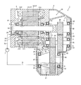
- FIG. 1 is a cross-sectional view of the rotary electric machine of the present embodiment.
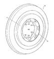
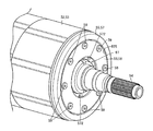
- FIG. 2 is a perspective view (front side) of the end plate.
- FIG. 3 is a perspective view (back side) of the end plate.
- FIG. 4 is a front view of the end plate.
- FIG. 5 is a side view of the end plate.
- FIG. 6 is a back view of the end plate.
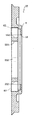
- FIG. 7 is a cross-sectional view of the end plate.
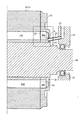
- FIG. 8 is a cross-sectional view of the rotor, the supply path, and the supply nozzle.
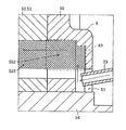
- FIG. 9 is a partially enlarged view of FIG. 8 and is a view when the refrigerant is supplied to the refrigerant reservoir.
- FIG. 9 is a partially enlarged view of FIG. 8 and is a view when the refrigerant is supplied to the refrigerant reservoir.
- FIG. 10 is a cross-sectional view showing a rotary electric machine of the first modification.
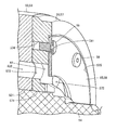
- FIG. 11 is a perspective view showing a rotary electric machine of the second modification.
- FIG. 12 is a cross-sectional view of FIG. 11 when the rotor is cut in a plane along the axial direction and the radial direction.
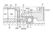
- FIG. 13 is a diagram showing a rotary electric machine of the third modification.
- FIG. 14 is a partially enlarged view of FIG.
- FIG. 15 is a diagram showing a rotary electric machine of the fourth modified example.
- FIG. 1 is a cross-sectional view of the rotary electric machine 1 of the present embodiment.
- the rotary electric machine 1 of the present embodiment has a configuration in which the motor 5 and the speed reducer 4 are housed in the housing 2.
- the axial direction is the axial direction (longitudinal direction) of the rotor core 53 (rotor shaft 54)
- the circumferential direction is the rotational direction around the axis of the rotor core 53 (rotor shaft 54).
- the direction means the radial direction of the rotor core 53 (rotor shaft 54).
- the housing 2 has an internal space that can accommodate the motor 5 and the reduction gear 4, and the lowermost portion of the portion that accommodates the reduction gear 4 is a storage tank 21 that stores lubricating oil.
- the speed reducer 4 includes a first gear 41 that rotates with the rotation of the rotor shaft 54 of the motor 5, a second gear 43 that meshes with the first gear 41 and rotates in the opposite direction to the first gear 41, and a second gear 43.
- a third gear 44 that rotates coaxially, a fourth gear 46 that meshes with the third gear 44 and rotates in the opposite direction to the third gear 44, and a bearing portion 47 that rotates coaxially with the fourth gear 46 are provided.
- the first gear 41 is pivotally supported by the shaft 42, and the shaft 42 is connected to the rotor shaft 54 so as to be coaxial. Further, the shaft 42 is rotatably supported by a support portion 22 fixed to the housing 2 (or integrated with the housing 2) via bearings 3 at both ends in the longitudinal direction.
- the second gear 43 and the third gear 44 are pivotally supported by a shaft 45, and the shaft 45 is rotatably supported by a support portion 22 via a bearing 3.
- the bearing portion 47 is rotatably supported by the support portion 22 via the bearing 3 and is connected to a drive shaft (not shown) connected to the wheel.
- the second gear 43 is designed to have a larger diameter (more teeth) than the first gear 41
- the third gear 44 has a smaller diameter (fewer teeth) than the second gear 43
- the fourth gear 46 is designed to have a larger diameter (more teeth) than the third gear 44.
- the lower part of the fourth gear 46 is immersed in the lubricating oil stored in the storage tank 21, and when the fourth gear 46 rotates, the lubricating oil stored in the storage tank 21 is scooped up.
- a catch tank 23 (tank) is provided at a position directly above the fourth gear 46 of the housing 2, and a part of the lubricating oil scooped up by the fourth gear 46 is stored.
- the lubricating oil stored in the catch tank 23 (refrigerant supply means) is supplied to the motor 5 as described later.
- the motor 5 is composed of a stator 51 and a rotor 52.
- the stator 51 is composed of a tubular stator core 511 and a stator coil 512 wound around the stator core 511.
- the stator core 511 is formed by laminating a large number of electrical steel sheets punched in an annular shape in the axial direction.
- a plurality of teeth (not shown) arranged at equal intervals in the circumferential direction are arranged on the inner side surface of the stator core 511, and the stator coil 512 is wound around each tooth.
- a gap may be formed between the outer side surface of the stator core 511 and the housing 2 so that lubricating oil (oil) can flow.
- the rotor 52 includes a rotor shaft 54 and a rotor core 53 pivotally supported by the rotor shaft 54.
- the rotor shaft 54 is rotatably supported by the support portion 22 via bearings 3 at both ends in the longitudinal direction.
- the rotor core 53 is formed by laminating a large number of electromagnetic steel plates punched in an annular shape in the axial direction, but the rotor core 53 may be integrally formed by sintering a powdery alloy.
- the rotor core 53 is formed in such a manner that an insertion hole 531 through which the rotor shaft 54 is inserted communicates with the electromagnetic steel plate in the center.
- the rotor core 53 is formed with a plurality of oil flow paths 532 that penetrate in the axial direction and are arranged in the circumferential direction at the same position in the radial direction so as to communicate with the electromagnetic steel plate.
- a magnet accommodating hole (not shown) for accommodating a magnet (not shown) adjacent to 532 is also formed so as to communicate with the rotor core 53.
- the end plate 55 is arranged at the end of the rotor core 53 on the reduction gear 4 side in the longitudinal direction (axial direction), and the end plate 56 is arranged at the end on the opposite side.
- the end plate 55 has the same shape as the rotor core 53 (electrical steel sheet), has a shape that communicates with the insertion hole 531 and the oil flow path 532, and further includes an outer wall portion 6 described later.
- the end plate 56 also has a shape that communicates with the insertion hole 531 and the oil flow path 532, but the outer wall portion 6 is not provided.
- the housing 2 is provided with lubricating oil supply means (refrigerant supply means) for supplying lubricating oil (refrigerant) from the catch tank 23 to the rotor core 53 via the end plate 55.
- lubricating oil supply means for example, a supply path 24 (refrigerant supply path) that penetrates the support portion 22 for fixing the rotor shaft 54 and the shaft 42 and communicates with the lower part of the catch tank 23, and supplies the lubricating oil.
- a supply nozzle 25 (refrigerant supply path), which is connected to the other side of the path 24 and whose tip is arranged close to the end plate 55, is provided.
- the shape of the supply path 24 is not limited to the case shown in FIG. 1, and can be arbitrarily designed.
- the lubricating oil supplied from the supply nozzle 25 is supplied to the end plate 55.
- the end plate 55 includes the outer wall portion 6, the lubricating oil flows as a refrigerant to the oil flow path 532 to cool the rotor core 53.
- the lubricating oil that cooled the rotor core 53 is discharged from the end plate 56.
- the lubricating oil discharged from the end plate 56 is scattered outward in the radial direction by the centrifugal force of the rotor core 53 and is supplied to the stator 51 to cool the stator 51.
- the lubricating oil is preferentially supplied to the end plate 56 side of the stator 51, but since the lubricating oil is supplied to the stator 51 one after another, the lubricating oil also moves to the end plate 55 side of the stator 51. As a result, it is supplied to the entire stator 51.
- the lubricating oil supplied to the stator 51 is then temporarily stored in the lower part of the area accommodating the stator 51 of the housing 2.
- a discharge hole 26 is formed in the lower part of the region of the housing 2, and the lubricating oil flows out from the discharge hole 26 and is returned to the storage tank 21.
- the catch tank 23 When supplying lubricating oil from the catch tank 23 to the rotor core 53 as described above, the catch tank 23 needs to be arranged at a height equal to or higher than the rotor shaft 54 of the motor 5.
- FIG. 2 is a perspective view (front side) of the end plate 55.
- FIG. 3 is a perspective view (back side) of the end plate 55.
- FIG. 4 is a front view of the end plate 55.
- FIG. 5 is a side view of the end plate 55.
- FIG. 6 is a back view of the end plate 55.
- FIG. 7 is a cross-sectional view of the end plate 55.
- the end plate 55 has a circular shape in a plan view, and an insertion hole 551 through which the rotor shaft 54 is inserted is formed in the central portion.
- a groove is formed in the rotor shaft 54 in the longitudinal direction, and a notch 553 that engages with the groove is arranged in the insertion hole 551 of the end plate 55 (the same applies to the end plate 56 and the rotor core 53). ing.
- the end plates 55 and 56 and the rotor core 53 from rotating (idle) in the circumferential direction with respect to the rotor shaft 54.
- the arrangement of the rotor core 53 at the time of stacking can be maintained, it is possible to maintain a state in which the oil flow path 532 and the magnet accommodating holes (not shown) are communicated with each other in the axial direction.
- An oil flow path 552 communicating with the oil flow path 532 of the rotor core 53 is formed at a position around the outside of the insertion hole 551 of the end plate 55, and is equal to the circumferential direction like the oil flow path 532 of the rotor core 53. Multiple are arranged at intervals.
- the end plate 55 of the present embodiment includes a hood-shaped outer wall portion 6.
- the outer wall portion 6 extends axially in a ring shape concentrically with the insertion hole 551 from a position radially outside the oil flow path 552 on one main surface of the end plate 55, and is radially inward in the middle. It has a bent shape.
- the inner peripheral surface is arranged at a position radially inside the outermost radial position (the outermost position in the radial direction) of the oil flow path 532 when viewed from the axial direction, and is arranged in the axial direction.
- a circular opening 61 is formed to open.
- the diameter of the inner peripheral surface of the opening 61 is designed to be at least larger than the diameter of the rotor shaft 54.
- the inner peripheral surface is separated from the rotor shaft 54, and the rotor shaft 54 is inserted substantially concentrically with the opening 61.
- the opening 61 has a ring shape in which the inner peripheral surface of the opening 61 is the outer inner wall and the side surface of the rotor shaft 54 is the inner inner wall.
- the region inside the outer wall portion 6 and the oil flow path 552 that is radially outside from the inner peripheral surface of the opening 61 functions as the oil sump portion 62 (FIG. 7).
- the oil reservoir 62 (refrigerant reservoir) communicates with the oil flow path 532, and the lubricating oil (refrigerant) supplied to the oil reservoir 62 is supplied to the oil flow path 532 by centrifugal force as described later. ..
- the region outside the outer wall portion 6 of the end plate 55 (the same applies to the end plate 56) in the radial direction functions as a holding portion for holding the rotor core 53 from the axial direction.
- the end plates 55 and 56 are preferably made of non-magnetic metal or ceramic. When the end plates 55 and 56 are formed of metal, they can be formed by gravity casting, and if they are ceramic, they can be formed by firing a ceramic material.
- FIG. 8 is a cross-sectional view of the rotor 52, the supply path 24, and the supply nozzle 25.
- FIG. 9 is a partially enlarged view of FIG. 8 and is a view when lubricating oil is supplied to the oil sump portion 62. Note that the lubricating oil is not shown in FIG.
- a supply path 24 communicating with the catch tank 23 (not shown in FIG. 8) is formed in the support portion 22, and the base end of the supply nozzle 25 is connected to the tip of the supply path 24.
- the tip of the supply nozzle 25 is inserted into the ring-shaped opening 61.
- the motor 5 rotor shaft 54
- the speed reducer 4 rotates
- the fourth gear 46 scoops up the lubricating oil to supply the lubricating oil to the catch tank 23 (FIG. 1).
- the lubricating oil stored in the catch tank 23 (FIG. 1) flows into the supply path 24 by gravity and is supplied to the supply path 24 and the supply nozzle 25.
- lubricating oil (indicating the direction of flow with an arrow) is supplied from the supply nozzle 25 to the opening 61 of the outer wall portion 6 and adheres to the main surface of the end plate 55 or the inner wall of the outer wall portion 6. Then, due to its own viscosity, the lubricating oil is brought by the rotating end plate 55 or the outer wall portion 6 to rotate in the circumferential direction and disperse in the circumferential direction. At this time, centrifugal force is applied to the lubricating oil. Then, the lubricating oil moves outward in the radial direction due to centrifugal force, and moves to the oil reservoir 62. Then, by continuing to supply the lubricating oil, the lubricating oil is stored in the oil reservoir 62.
- the lubricating oil stored in the oil reservoir 62 continues to receive centrifugal force, but its movement in the radial direction is restricted by the oil flow path 532 and the outer wall portion 6. Therefore, the lubricating oil stored in the oil reservoir 62 can move to the oil flow path 532 side or the outer wall portion 6 side in the axial direction by receiving pressure from the radial direction, but the movement to the outer wall portion 6 side is restricted. Therefore, the lubricating oil stored in the oil reservoir 62 eventually flows into the oil flow path 532.
- the lubricating oil flows into the oil flow path 532 one after another, is discharged from the other end (end plate 56) of the oil flow path 532, and is sprinkled radially outward by centrifugal force. It is scattered and supplied to the stator 51.
- the lubricating oil can be stored up to the position of the outer inner wall of the opening 61 in the radial direction.
- the hatched regions in the oil reservoir 62 (oil flow path 552) and the oil flow path 532 are shown as regions in which the lubricating oil can be stored.
- the lubricating oil has the outermost diameter in the oil flow path 532. It is filled (stored) from the position to the same position in the radial direction as the inner peripheral surface of the opening 61.
- the oil flow path 532 may be completely filled with lubricating oil or partially filled as described above.
- the supply nozzle 25 may be at least at any position as long as it can supply lubricating oil to the opening 61.
- the supply nozzle 25 is arranged at a position facing the opening 61 and above the rotor shaft 54, and the tip thereof is arranged so as to enter the opening 61.
- the supply nozzle 25 may be arranged at a position facing the opening 61 and below the rotor shaft 54 (may be left or right) so that the tip thereof enters the opening 61. .. Further, when the injection strength of the lubricating oil supplied from the supply nozzle 25 is high, it is not necessary to insert the tip of the supply nozzle 25 into the opening 61.
- the distance between the tip of the supply nozzle 25 and the main surface of the end plate 55 is such that the lubricating oil can bridge between the end plate 55 and the supply nozzle 25 due to the surface tension of the lubricating oil. ..
- the lubricating oil can be reliably supplied to the end plate 55, and leakage from the opening 61 of the lubricating oil can be reduced.
- the flow rate of the lubricating oil supplied from the supply nozzle 25 is supplied from the oil reservoir 62 to the oil flow path 532. It is also possible to increase the flow rate of the lubricating oil to be applied. At this time, the lubricating oil overflows from the oil sump portion 62 (outer wall portion 6), is scattered by centrifugal force, and is supplied to the catch tank 23 side of the stator 51.
- FIG. 10 is a cross-sectional view showing the rotary electric machine 1 of the first modification.
- the diameter of the oil flow path 552 of the end plate 55 is larger than the diameter of the oil flow path 532 of the rotor core 53, and the outermost diameter position of the oil flow path 552 is the oil flow. It is located radially outside the outermost diameter position of the road 532.
- the capacity of the oil reservoir 62 can be increased so that the lubricating oil can be stably supplied to the rotor core 53.
- the lubricating oil stored at a position outside the outermost diameter position of the oil flow path 532 of the oil reservoir 62 in the radial direction does not directly go to the oil flow path 532 due to centrifugal force, but is newly supplied. It will be directed toward the oil flow path 532 in a manner of being extruded by the lubricating oil to be produced. Further, since the stored lubricating oil is in a state of rotating together with the end plate 55, the newly supplied lubricating oil can be easily taken by the viscosity and drawn into the oil reservoir 62, so that the opening Leakage of lubricating oil from the portion 61 can be reduced.
- FIG. 11 is a perspective view showing the rotary electric machine 1 of the second modification.
- FIG. 12 is a cross-sectional view of FIG. 11 when the rotor 52 is cut in a plane along the axial direction and the radial direction.
- the end plate 55 has a configuration in which the main body 57 and the mounting portion 58 are separated.
- the main body 57 includes an insertion hole 571 that communicates with the insertion hole 531 of the rotor core 53, and an oil flow path 572 that communicates with the oil flow path 532 of the rotor core 53.
- the main body 57 projects in a ring shape in the axial direction concentrically with the insertion hole 571 so that the position on one main surface, which is radially outside the oil flow path 572, is the inner wall.
- the inner wall of the ring-shaped protruding portion of the main body 57 forms a portion that is the outermost diameter position of the inner wall of the oil pool portion 62 (FIG. 9).
- the mounting portion 58 is a ring-shaped member that includes the inner peripheral surface of the opening 61 and covers the oil pool portion 62 when viewed from the axial direction.
- the mounting portion 58 forms a portion which is an inner wall of the oil collecting portion 62 and is located at a position farthest from the end plate 55.
- bolt holes 574 are arranged in the main body 57 at predetermined intervals in the circumferential direction, and through holes 581 communicating with the bolt holes 574 are formed in the mounting portion 58.
- the bolt 59 is inserted into the through hole 581 and further screwed into the bolt hole 574.
- the mounting portion 58 is mounted so as to be concentric with the main body 57 by bolting.
- any attachment method such as adhesion, caulking, spot welding, etc. can be applied in addition to the bolt tightening shown in FIGS. 11 and 12.
- the main body 57 is formed with a counterbore 575 for accommodating the mounting portion 58 at a depth substantially the same as the thickness of the mounting portion 58, but it may be omitted. ..
- the end plate 55 can be easily manufactured by assembling the end plate 55 with two members.
- FIG. 13 is a diagram showing a rotary electric machine 1 of a third modification.
- FIG. 14 is a partially enlarged view of FIG.
- the axial distance between the bearing 3 supporting the rotor shaft 54 and the rotor 52 is short, and when the end plate 55 of the present embodiment is applied, the supply nozzle 25 (FIG. 8) is attached. It is a suitable form when it becomes difficult.
- the support portion 22 that supports the bearing 3 is a vertically long portion 221 that is fixed to the housing 2 and has a supply path 24 that communicates with the catch tank 23, and is supported by the vertically long portion 221 and has an outer shape (circular shape) of the bearing 3. ) Is provided, and a cylindrical portion 222 in which the bearing 3 is fitted is provided in the inner wall.
- the base end of the cylindrical portion 222 is connected to the vertically elongated portion 221 and the tip thereof faces the outer wall portion 6.
- the outer side surface of the cylindrical portion 222 has a tapered shape in which the diameter decreases from the intermediate position from the base end to the tip toward the tip, but the taper shape is omitted and the diameter is the same from the base end to the tip. It may be.
- a supply groove 223 extending in the axial direction and through which lubricating oil flows is arranged in the upper part of the cylindrical portion 222.
- the supply path 24 arranged in the vertically elongated portion 221 is bent toward the supply groove 223 at a position at the same height as the supply groove 223 and opens on the side surface of the vertically elongated portion 221 so that the supply path 24 and the supply groove 223 communicate with each other.
- the bearing 3 that pivotally supports the rotor shaft 54 is pushed in from the tip of the cylindrical portion 222, and the outer peripheral portion of the bearing 3 comes into contact with the stopper 224 formed on the inner wall, so that the bearing 3 is connected to the cylindrical portion 222. Therefore, the inner wall of the cylindrical portion 222 cannot be made smaller than the outer diameter of the outer peripheral portion of the bearing 3.
- the rotor shaft 54 is inserted into the inner peripheral portion of the bearing 3, and the stopper 541 formed on the side surface of the rotor shaft 54 abuts on the inner peripheral portion of the bearing 3, so that the rotor shaft 54 is inserted into the bearing 3. Is supported by.
- the tip of the cylindrical portion 222 faces the outer wall portion 6 as described above, it is difficult to directly supply the lubricating oil from the end portion of the supply groove 223 to the opening 61 formed in the outer wall portion 6. Is.
- an additional ring 225 that is concentrically connected to the cylindrical portion 222 by being connected to the inner wall of the cylindrical portion 222 is applied.
- the additional ring 225 extends axially from the base end portion 225a connected to the cylindrical portion 222 and the base end portion 225a in a state where the outer diameter is smaller than that of the base end portion 225a and enters the opening 61. It is provided with a protrusion 225b.
- the supply groove 223 of the cylindrical portion 222 extends at the tip end surface facing the outer wall portion 6 and extends toward the additional ring 225.
- the additional ring 225 communicates with the supply groove 223 extending to the end surface of the cylindrical portion 222, and bends from the end surface of the base end portion 225a on the outer wall portion 6 side to the upper surface of the extending portion 225b to the tip of the extending portion 225b.
- An extending supply groove 226 is formed.
- the bearing 3 is first fitted into the cylindrical portion 222 (stopper 224), then the additional ring 225 is connected to the cylindrical portion 222, the rotor shaft 54 is inserted through the additional ring 225, and the bearing 3 is inserted as it is.
- the rotor shaft 54 (stopper 541) may be connected to the bearing 3.
- Adhesion, caulking, spot welding, or the like can be applied to the connection of the bearing 3 to the cylindrical portion 222, the connection of the additional ring 225 to the cylindrical portion 222, and the connection of the rotor shaft 54 to the bearing 3.
- the lubricating oil flowing through the supply path 24 in the vertically elongated portion 221 flows out from the tip of the supply groove 226 of the additional ring 225 via the supply groove 223 of the cylindrical portion 222 and is supplied into the opening 61. .. Further, a part of the lubricating oil passing through the supply groove 223 of the cylindrical portion 222 does not enter the supply groove 226 of the additional ring 225 and is supplied to the surface of the outer wall portion 6. Then, the lubricating oil supplied into the opening 61 flows into the oil flow path 532 via the oil reservoir 62, and the lubricating oil supplied to the surface of the outer wall portion 6 is scattered on the stator 51 by centrifugal force.
- the supply groove 223 of the cylindrical portion 222 and the supply groove 226 of the additional ring 225 can be closed to form a tubular supply path, leaving a portion that is the end of the lubricating oil flow path.
- all the lubricating oil flowing through the supply path 24 in the vertically elongated portion 221 is discharged (injected) from the tip of the additional ring 225, so that the lubricating oil can be reliably supplied into the opening 61.
- FIG. 15 is a diagram showing a rotary electric machine 1 of a fourth modified example.
- the rotary electric machine 1 of the fourth embodiment is configured to supply the lubricating oil stored in the storage tank 21 to the end plate 55 (rotor core 53) by using the oil pump 7 (pump, refrigerant supply means).
- the lubricating oil stored in the catch tank 23 is exclusively supplied to the speed reducer 4.
- the end plate 55 is attached to the end opposite to the end of the rotor core 53 on the reducer 4 side.
- the end plate 56 is attached to the end of the rotor core 53 on the reducer 4 side.
- the supply path 24 for supplying the lubricating oil to the end plate 55 is arranged so as to penetrate the support portion 22 from the end portion of the housing 2 on the motor 5 side.
- the supply nozzle 25 is attached to the supply path 24, and its tip faces the opening 61.
- the oil pump 7 is arranged outside the housing 2, it may be arranged inside the housing 2.
- One end of the suction pipe 71 is connected to the suction side of the oil pump 7, and one end of the discharge pipe 72 is connected to the discharge side.
- the other end of the suction pipe 71 is connected to a portion of the housing 2 that becomes a storage tank 21 and communicates with the storage tank 21.
- the other end of the discharge pipe 72 is connected to the supply path 24.
- the supply path 24 and the supply nozzle 25 are arranged at positions facing the lower part of the opening 61, but they may be arranged at any position as long as they face the opening 61. Further, when the injection strength of the lubricating oil supplied from the supply nozzle 25 is high, it is not necessary to insert the tip of the supply nozzle 25 into the opening 61.
- the flow rate of the lubricating oil can be appropriately controlled by arbitrarily adjusting the output of the oil pump 7. ..
- the lubricating oil can be appropriately controlled by arbitrarily adjusting the output of the oil pump 7. ..
- the lubricating oil overflows from the oil reservoir 62 and is adjacent to the end plate 55 of the stator 51. It is possible to supply lubricating oil directly to the part.
- the end plate 55 is attached to the end of the rotor core 53 on the opposite side of the speed reducer 4 side, and the supply nozzle 25 is arranged so as to face the opening 61 of the outer wall portion 6.
- the end plate 55 may be attached to the end of the rotor core 53 on the reducer 4 side, and the supply nozzle 25 may be arranged so as to face the opening 61 of the outer wall portion 6. Since the lubricating oil is supplied to the end plate 55 (rotor core 53) by using the oil pump 7 in this way, the degree of freedom in arranging the end plate 55 and the supply nozzle 25 can be increased.
- the rotor core 53 has a plurality of pieces that penetrate in the axial direction and are arranged in the circumferential direction.
- a refrigerant flow path (oil flow path 532) is formed, and the end plate 55 includes an outer wall portion 6 that forms a refrigerant reservoir portion (oil reservoir portion 62) communicating with a plurality of refrigerant flow paths (oil flow path 532).
- An opening 61 through which the rotor shaft 54 that pivotally supports the rotor core 53 is inserted is formed in the outer wall portion 6, and the inner peripheral surface of the opening 61 is separated from the rotor shaft 54 and is a refrigerant when viewed from the axial direction. It is located inside the outermost position in the radial direction of the flow path (oil flow path 532).
- the outer wall portion 6 is arranged so as to cover at least a part of the refrigerant flow path (oil flow path 532) and outside in the radial direction when viewed from the axial direction, or the refrigerant flow path (oil flow path 532). It is arranged so as to cover the entire oil flow path 532).
- the stored refrigerant (lubricating oil) continues to receive centrifugal force, but the outer wall 6 restricts the movement of the refrigerant (lubricating oil) in the direction away from the rotor core 53, resulting in the refrigerant flow path (oil flow path 532). It flows in. Therefore, when the refrigerant (lubricating oil) is continuously supplied to the refrigerant reservoir (oil reservoir 62) through the opening 61, the refrigerant (lubricating oil) continuously flows to the refrigerant flow path (oil flow path 532). To do.
- the lubricating oil can be passed through the rotor core 53 as a refrigerant, so that the rotor 52 is inexpensive and has good heat removal properties. It becomes the rotary electric machine 1 to include.
- the refrigerant supply means (supply path 24, supply nozzle 25) for supplying the refrigerant to the rotor core 53 from the outside of the rotor core 53 is included, and the tip of the refrigerant supply means (supply nozzle 25) has an opening 61 in the axial direction. It is arranged on the rotor core 53 side.
- the lubricating oil supplied from the refrigerant supply means (supply path 24, supply nozzle 25) surely adheres to the region inside the outer wall portion 6 of the end plate 55, so that the lubricating oil leaks from the opening 61. Can be reduced.
- the refrigerant supply means (supply path 24, supply nozzle 25) for supplying the refrigerant to the rotor core 53 from the outside of the rotor core 53 is included, and the tip of the refrigerant supply means (supply nozzle 25) has an opening 61 in the radial direction. It is arranged inside the inner peripheral surface of.
- the lubricating oil can be supplied to the opening 61 without allowing the refrigerant supply means (supply nozzle 25) to enter the opening 61, so that the refrigerant supply means
- the degree of freedom in arranging the (supply nozzle 25) can be increased.
- the refrigerant supply means is a tank (catch tank 23) for storing the refrigerant (lubricating oil) and a refrigerant (catch tank 23) to the refrigerant reservoir (oil reservoir 62) via the opening 61. It includes a refrigerant supply path (supply path 24, supply nozzle 25) for supplying (lubricating oil).
- supply path 24, supply nozzle 25 for supplying (lubricating oil).
- the refrigerant supply means is discharged from the pump (oil pump 7) to the refrigerant reservoir (oil reservoir 62) via the pump (oil pump 7) that pumps the refrigerant (lubricating oil) and the opening 61.
- It includes a refrigerant supply path (supply path 24, supply nozzle 25) for supplying the fuel (lubricating oil).
- the refrigerant (lubricating oil) can be supplied to the rotor core 53 with a simple configuration.
- the refrigerant lubricating oil
- the pump oil pump 7
- the degree of freedom in arranging the refrigerant supply passages (supply passage 24, supply nozzle 25) and the end plate 55 can be increased.
- the outermost outer diameter position of the refrigerant reservoir (oil reservoir 62) in the radial direction is located outside the refrigerant flow path (oil flow path 532) in the radial direction.
- the capacity of the refrigerant reservoir (oil reservoir 62) can be increased to stably supply the refrigerant (lubricating oil) to the rotor core 53.
- the refrigerant (lubricating oil) stored in the outermost position in the radial direction from the outermost diameter position of the refrigerant flow path (oil flow path 532) of the refrigerant reservoir (oil reservoir 62) is directly refrigerant by centrifugal force.
- the end plate 55 includes the main body 57 including the outermost outer diameter position in the radial direction in the refrigerant reservoir (oil reservoir 62), the inner peripheral surface of the opening 61, and the shaft.
- the mounting portion 58 that covers the refrigerant collecting portion (oil collecting portion 62) when viewed from the direction is included, and the refrigerant collecting portion (oil collecting portion 62) is formed by attaching the mounting portion 58 to the main body 57.
- the end plate 55 can be easily manufactured by assembling the end plate 55 with two members.
Landscapes
- Engineering & Computer Science (AREA)
- Power Engineering (AREA)
- Motor Or Generator Cooling System (AREA)
Abstract
口ータコアと、口ータコアの端部に当接するエンドプレートと、を備える回転電機において、口ータコアには、軸方向に貫通するとともに周方向に配列された複数の冷媒流路(オイル流路)が形成され、エンドプレートは、複数の冷媒流路(オイル流路)に連通する冷媒溜り部(オイル溜り部)を形成する外壁部を含み、外壁部には、口—タコアを軸支する口ータシャフトが揷通する開口部が形成され、開口部の内周面は、口ータシャフトから離間しているとともに、軸方向から見て冷媒流路(オイル流路)の径方向において最も外側となる位置よりも内側に位置する。
Description
この発明は、回転電機に関する。
JP2012−235546Aは、ロータコアとエンドプレートがロータシャフトにより軸支されたロータにおいて、ロータシャフト内で軸方向に延びる冷媒流路と、当該冷媒流路から径方向に分岐しロータシャフトの側面に開口してロータコア内の冷媒流路に連通する流通孔と、を設けた構成を開示している。
しかし、上記のように、ロータシャフトに対して前記の冷媒流路及び流通孔を形成すると、ロータシャフトが高価になるという問題があった。
そこで、本発明は、ロータシャフトを介さずに冷媒をロータコア内の冷媒流路に供給可能な回転電機を提供することを目的とする。
本発明のある態様によれば、ロータコアと、ロータコアと、前記ロータコアの端部に当接するエンドプレートと、を備える回転電機において、前記ロータコアには、軸方向に貫通するとともに周方向に配列された複数の冷媒流路が形成され、前記エンドプレートは、複数の前記冷媒流路に連通する冷媒溜り部を形成する外壁部を含み、前記外壁部には、前記ロータコアを軸支するロータシャフトが挿通する開口部が形成され、前記開口部の内周面は、前記ロータシャフトから離間しているとともに、前記軸方向から見て前記冷媒流路の径方向において最も外側となる位置よりも内側に位置する。
[回転電機の基本構成]
図1は、本実施形態の回転電機1の断面図である。本実施形態の回転電機1は、ハウジング2にモータ5と減速機4が収容された構成を備えている。なお、本実施形態において、軸方向とは、ロータコア53(ロータシャフト54)の軸方向(長手方向)であり、周方向とはロータコア53(ロータシャフト54)の軸周りの回転方向であり、径方向とはロータコア53(ロータシャフト54)の動径方向を意味するものとする。
図1は、本実施形態の回転電機1の断面図である。本実施形態の回転電機1は、ハウジング2にモータ5と減速機4が収容された構成を備えている。なお、本実施形態において、軸方向とは、ロータコア53(ロータシャフト54)の軸方向(長手方向)であり、周方向とはロータコア53(ロータシャフト54)の軸周りの回転方向であり、径方向とはロータコア53(ロータシャフト54)の動径方向を意味するものとする。
ハウジング2は、モータ5及び減速機4を収容可能な内部空間を有しており、減速機4を収容する部分の最下部は潤滑オイルを蓄える貯留タンク21となっている。
減速機4は、モータ5のロータシャフト54の回転とともに回転する第1ギア41と、第1ギア41に噛み合うとともに第1ギア41と逆方向に回転する第2ギア43と、第2ギア43と同軸で回転する第3ギア44と、第3ギア44に噛み合うとともに第3ギア44と逆方向に回転する第4ギア46と、第4ギア46と同軸で回転する軸受け部47と、を備える。
第1ギア41はシャフト42に軸支され、当該シャフト42がロータシャフト54に同軸となるように接続されている。またシャフト42は、長手方向の両端においてベアリング3を介してハウジング2に固定された(若しくはハウジング2と一体となっている)支持部22に回転自在に支持されている。
第2ギア43及び第3ギア44は、シャフト45により軸支され、当該シャフト45はベアリング3を介して支持部22に回転自在に支持されている。
軸受け部47は、ベアリング3を介して支持部22に回転自在に支持されるとともに車輪に結合するドライブシャフト(不図示)が接続されている。
ここで、第2ギア43は第1ギア41よりも径が大きく(歯数が多く)なるように設計され、第3ギア44は第2ギア43よりも径が小さく(歯数が少なく)なるように設計され、第4ギア46は第3ギア44よりも径が大きく(歯数が多く)なるように設計されている。これにより、ロータ52(ロータシャフト54)の回転数>シャフト45の回転数>軸受け部47の回転数となり、軸受け部47はロータ52よりも低い回転数で回転するとともに、ロータ52よりも高いトルクを得ることになる。
第4ギア46の下部は、貯留タンク21に貯留した潤滑オイルに浸漬した状態となっており、第4ギア46が回転すると貯留タンク21に貯留した潤滑オイルを上方にかき上げる。一方、ハウジング2の第4ギア46の真上となる位置にはキャッチタンク23(タンク)が設けられ、第4ギア46によりかき上げられた潤滑オイルの一部が貯留される。キャッチタンク23(冷媒供給手段)に貯留された潤滑オイルは後述のようにモータ5に供給される。
モータ5は、ステータ51とロータ52により構成される。ステータ51は、筒状のステータコア511と、ステータコア511に巻装されたステータコイル512により構成される。ステータコア511は、円環状に打ち抜き加工された多数の電磁鋼板を軸方向に積層して形成される。ステータコア511の内側側面には、周方向に等間隔に並べられた複数のティース(不図示)が配置され、各ティースにステータコイル512が巻回される。なお、ステータコア511はハウジング2に固定されるが、ステータコア511の外側側面とハウジング2の間に隙間を形成して潤滑オイル(オイル)を流通できるようにしてもよい。
ロータ52は、ロータシャフト54と、ロータシャフト54に軸支されたロータコア53と、を備える。ロータシャフト54は、長手方向の両端においてベアリング3を介して支持部22に回転自在に支持されている。
ロータコア53は、ステータコア511と同様に、円環状に打ち抜き加工された多数の電磁鋼板を軸方向に積層して形成されるが、粉末状の合金を焼結させて一体で形成してもよい。ロータコア53は、中央にロータシャフト54を挿通する挿通孔531が電磁鋼板を連通する態様で形成されている。また、ロータコア53には、軸方向に貫通するとともに径方向で同一の位置において周方向に並ぶように複数配列されたオイル流路532が電磁鋼板を連通する態様で形成され、さらに当該オイル流路532に隣接して磁石(不図示)を収容する磁石収容孔(不図示)もロータコア53を連通する態様で形成されている。
ロータコア53の長手方向(軸方向)の減速機4側の端部にはエンドプレート55が配置され、その反対側の端部にはエンドプレート56が配置されている。
エンドプレート55は、ロータコア53(電磁鋼板)と同様の形状であって、挿通孔531及びオイル流路532に連通する形状を備え、さらに後述の外壁部6を備える。エンドプレート56も、挿通孔531及びオイル流路532に連通する形状を備えるが外壁部6は設けられていない。
一方、ハウジング2には、キャッチタンク23からエンドプレート55を介してロータコア53に潤滑オイル(冷媒)を供給するための潤滑オイル供給手段(冷媒供給手段)が配置されている。潤滑オイル供給手段としては、例えば、ロータシャフト54及びシャフト42を固定するための支持部22を貫通し、一方がキャッチタンク23の下部に連通している供給路24(冷媒供給路)と、供給路24の他方に接続され、その先端がエンドプレート55に近接して配置される供給ノズル25(冷媒供給路)と、を備える。なお供給路24の形状は、図1に示す場合に限らず任意に設計可能である。
詳細は後述するが、供給ノズル25から供給された潤滑オイルは、エンドプレート55に供給される。エンドプレート55が外壁部6を備えることで潤滑オイルは冷媒としてオイル流路532に流通してロータコア53を冷却する。ロータコア53を冷却した潤滑オイルはエンドプレート56から排出される。エンドプレート56から排出された潤滑オイルは、ロータコア53の遠心力により径方向外側に撒き散らされてステータ51に供給されステータ51を冷却する。
ステータ51において、潤滑オイルはステータ51のエンドプレート56側に優先的に供給されるが、潤滑オイルは次々とステータ51に供給されるため、潤滑オイルはステータ51のエンドプレート55側にも移動して結果的にステータ51全体に供給される。
ステータ51に供給された潤滑オイルはその後ハウジング2のステータ51を収容する領域の下部に一時的に蓄えられる。ハウジング2の当該領域の下部には排出孔26が形成され、潤滑オイルは排出孔26から流出して貯留タンク21に戻される。
なお、上記のようにキャッチタンク23からロータコア53に潤滑オイルを供給する場合、キャッチタンク23は少なくともモータ5のロータシャフト54と同程度かそれ以上の高さに配置する必要がある。
[エンドプレート]
図2は、エンドプレート55の斜視図(表側)である。図3は、エンドプレート55の斜視図(裏側)である。図4は、エンドプレート55の正面図である。図5は、エンドプレート55の側面図である。図6は、エンドプレート55の裏面図である。図7は、エンドプレート55の断面図である。
図2は、エンドプレート55の斜視図(表側)である。図3は、エンドプレート55の斜視図(裏側)である。図4は、エンドプレート55の正面図である。図5は、エンドプレート55の側面図である。図6は、エンドプレート55の裏面図である。図7は、エンドプレート55の断面図である。
図に示すように、エンドプレート55は、平面視で円形形状を有するとともに、中央部にロータシャフト54が挿通する挿通孔551が形成されている。図示は省略するがロータシャフト54には長手方向に溝が形成されており、エンドプレート55(エンドプレート56、ロータコア53も同様)の挿通孔551には当該溝に係合するノッチ553が配置されている。これによりエンドプレート55,56及びロータコア53がロータシャフト54に対して周方向に回転する(空回りする)ことを回避できる。また、ロータコア53についても、積層時の配置を維持できるのでオイル流路532及び磁石収容孔(不図示)がそれぞれ軸方向に連通した状態を維持することができる。
エンドプレート55の挿通孔551の外側を周回する位置には、ロータコア53のオイル流路532に連通するオイル流路552が形成されており、ロータコア53のオイル流路532と同様に周方向に等間隔に複数配置されている。
本実施形態のエンドプレート55は、フード状の外壁部6を備えている。外壁部6は、エンドプレート55の一方の主面において、オイル流路552よりも径方向外側となる位置から挿通孔551と同心にリング状に軸方向に延出するとともに途中で径方向内側に折れ曲がった形状を有している。
よって、外壁部6には、軸方向から見てオイル流路532の最外径位置(径方向で最も外側となる位置)よりも径方向内側となる位置に内周面が配置され軸方向に開口する円形の開口部61が形成される。開口部61の内周面の径は少なくともロータシャフト54の径よりも大きく設計されている。当該内周面はロータシャフト54から離間しており、ロータシャフト54は開口部61ほぼ同心で挿通する。これにより、開口部61は、開口部61の内周面を外側の内壁とし、ロータシャフト54の側面を内側の内壁としたリング形状となる。
また、外壁部6内及びオイル流路552内であって開口部61の内周面から径方向外側となる領域はオイル溜り部62(図7)として機能する。オイル溜り部62(冷媒溜り部)は、オイル流路532に連通しており、後述のようにオイル溜り部62に供給された潤滑オイル(冷媒)は遠心力によりオイル流路532に供給される。なお、エンドプレート55(エンドプレート56も同様)の外壁部6よりも径方向で外側となる領域はロータコア53を軸方向から抑える押さえ部として機能する。
エンドプレート55,56は、非磁性の金属やセラミックを材料とすることが好適である。エンドプレート55,56を金属で形成する場合は重力鋳造で形成可能であり、セラミックであればセラミック材料の燒結により形成可能である。
[潤滑オイルの供給態様]
図8は、ロータ52、供給路24、及び供給ノズル25の断面図である。図9は、図8の部分拡大図であってオイル溜り部62に潤滑オイルを供給した場合の図である。なお、図8では潤滑オイルの図示が省略されている。
図8は、ロータ52、供給路24、及び供給ノズル25の断面図である。図9は、図8の部分拡大図であってオイル溜り部62に潤滑オイルを供給した場合の図である。なお、図8では潤滑オイルの図示が省略されている。
図8に示すように、支持部22にはキャッチタンク23(図8では不図示)に連通する供給路24が形成され、当該供給路24の先端には供給ノズル25の基端が接続され、供給ノズル25の先端がリング状の開口部61に入り込んでいる。ここで、モータ5(ロータシャフト54)が回転すると、減速機4が回転し、第4ギア46(図1)が潤滑オイルをかき上げてキャッチタンク23(図1)に潤滑オイルを供給し、キャッチタンク23(図1)に蓄えられた潤滑オイルが重力により供給路24に流れ、供給路24及び供給ノズル25に供給される。
図9に示すように、潤滑オイル(矢印で流れる向きを表示)が供給ノズル25から外壁部6の開口部61に供給され、エンドプレート55の主面または外壁部6の内壁に付着する。すると、潤滑オイルは自身の粘性により、回転しているエンドプレート55または外壁部6に連れられて周方向に回転し且つ周方向に分散する。またこのとき、潤滑オイルに遠心力が印加される。すると潤滑オイルは遠心力により径方向外側に移動し、オイル溜り部62に移動する。そして、潤滑オイルを供給し続けることにより潤滑オイルがオイル溜り部62に貯留していく。
オイル溜り部62に貯留した潤滑オイルは、引き続き遠心力を受けるが、径方向への移動はオイル流路532及び外壁部6により制限される。よってオイル溜り部62に貯留した潤滑オイルは径方向から圧力を受けることで、軸方向でオイル流路532側または外壁部6側に移動し得るが外壁部6側への移動は制限される。したがってオイル溜り部62貯留した潤滑オイルは、結果的にオイル流路532に流れ込む。そして潤滑オイルを供給し続けることにより、潤滑オイルは次々とオイル流路532に流れ込んでいき、オイル流路532の他方の端部(エンドプレート56)から排出され、遠心力により径方向外側に撒き散らされステータ51に供給される。
なお供給ノズル25から供給された潤滑オイルが垂れ落ちてロータシャフト54等の他の場所に付着した場合であっても、当該潤滑オイルが外壁部6の開口部61内に有る限り、遠心力によりエンドプレート55の主面または外壁部6を介してオイル溜り部62に移動することができる。
図9に示すように、オイル溜り部62及びオイル流路532において、潤滑オイルは径方向において開口部61の外側の内壁の位置まで貯留可能である。図9においては、オイル溜り部62(オイル流路552)及びオイル流路532においてハッチングが施された領域が、潤滑オイルが貯留可能な領域として図示している。ここで、開口部61の内周面が、軸方向から見てオイル流路532の最内径位置(径方向で最も内側となる位置)より径方向内側にある場合、潤滑オイルをオイル流路532に完全に充填させることができる。しかし、図9に示すように、開口部61の内周面が、軸方向から見てオイル流路532の最内径位置より径方向外側にある場合、潤滑オイルはオイル流路532において最外径位置から開口部61の内周面と径方向で同じ位置まで充填(貯留)される。なお、モータ5の仕様により、オイル流路532に潤滑オイルを完全に充填させる場合と上記のような部分充填をする場合がある。
供給ノズル25は、少なくとも潤滑オイルを開口部61に供給可能な位置であればどの位置でもよい。図9では、供給ノズル25は開口部61に対向する位置であってロータシャフト54の上側となる位置に配置され、その先端が開口部61に入り込むように配置されている。または、供給ノズル25を開口部61に対向する位置であってロータシャフト54の下側(左側、右側でもよい)となる位置であってその先端が開口部61に入り込むように配置してもよい。さらに、供給ノズル25から供給される潤滑オイルの噴射強度が大きいときは、供給ノズル25の先端を開口部61に入り込ませる必要はない。なお、供給ノズル25の先端とエンドプレート55の主面との距離は、潤滑オイルの表面張力により潤滑オイルがエンドプレート55と供給ノズル25との間を橋渡し可能な距離にすることも好適である。これにより、潤滑オイルの供給量が少なくなっても潤滑オイルをエンドプレート55に確実に供給して、潤滑オイルの開口部61から漏出を低減できる。
また、供給ノズル25の内径を拡大する、または後述のオイルポンプ7(図15)を適用することにより、供給ノズル25から供給される潤滑オイルの流量をオイル溜り部62からオイル流路532に供給される潤滑オイルの流量よりも多くすることも可能である。このとき、潤滑オイルはオイル溜り部62(外壁部6)から溢れ出て遠心力により撒き散らされ、ステータ51のキャッチタンク23側に供給される。
[第1変形例の回転電機]
図10は、第1変形例の回転電機1を示す断面図である。第1変形例の回転電機1において、エンドプレート55は、オイル流路552の径がロータコア53のオイル流路532の径よりも大きくなっており、オイル流路552の最外径位置がオイル流路532の最外径位置よりも径方向外側に位置している。これにより、オイル溜り部62の容量を大きくして潤滑オイルをロータコア53に安定的に供給することができる。また、オイル溜り部62のオイル流路532の最外径位置よりも径方向で外側に位置に貯留している潤滑オイルは遠心力により直接オイル流路532に向かうことはないが、新たに供給される潤滑オイルに押し出される態様でオイル流路532に向かうことになる。また当該貯留している潤滑オイルは、エンドプレート55とともに回転している状態であるので、新たに供給される潤滑オイルを粘性により容易に連れまわしてオイル溜り部62に引き込むことができるので、開口部61からの潤滑オイルの漏出を低減できる。
図10は、第1変形例の回転電機1を示す断面図である。第1変形例の回転電機1において、エンドプレート55は、オイル流路552の径がロータコア53のオイル流路532の径よりも大きくなっており、オイル流路552の最外径位置がオイル流路532の最外径位置よりも径方向外側に位置している。これにより、オイル溜り部62の容量を大きくして潤滑オイルをロータコア53に安定的に供給することができる。また、オイル溜り部62のオイル流路532の最外径位置よりも径方向で外側に位置に貯留している潤滑オイルは遠心力により直接オイル流路532に向かうことはないが、新たに供給される潤滑オイルに押し出される態様でオイル流路532に向かうことになる。また当該貯留している潤滑オイルは、エンドプレート55とともに回転している状態であるので、新たに供給される潤滑オイルを粘性により容易に連れまわしてオイル溜り部62に引き込むことができるので、開口部61からの潤滑オイルの漏出を低減できる。
[第2変形例の回転電機]
図11は、第2変形例の回転電機1を示す斜視図である。図12は、図11においてロータ52を軸方向及び径方向に沿った平面で切断した場合の断面図である。第2変形例の回転電機1において、エンドプレート55が本体57と取り付け部58とに分離した構成を有している。本体57は、ロータコア53の挿通孔531に連通する挿通孔571と、ロータコア53のオイル流路532に連通するオイル流路572を備えている。また本体57は、一方の主面において、オイル流路572よりも径方向外側となる位置が内壁となるように挿通孔571と同心で軸方向にリング状に突出している。本体57のリング状に突出した部分の内壁は、オイル溜り部62(図9)の内壁の最外径位置となる部分を形成する。
図11は、第2変形例の回転電機1を示す斜視図である。図12は、図11においてロータ52を軸方向及び径方向に沿った平面で切断した場合の断面図である。第2変形例の回転電機1において、エンドプレート55が本体57と取り付け部58とに分離した構成を有している。本体57は、ロータコア53の挿通孔531に連通する挿通孔571と、ロータコア53のオイル流路532に連通するオイル流路572を備えている。また本体57は、一方の主面において、オイル流路572よりも径方向外側となる位置が内壁となるように挿通孔571と同心で軸方向にリング状に突出している。本体57のリング状に突出した部分の内壁は、オイル溜り部62(図9)の内壁の最外径位置となる部分を形成する。
取り付け部58は、開口部61の内周面を包含するとともに軸方向から見てオイル溜り部62を覆うリング状の部材である。取り付け部58は、オイル溜り部62の内壁であってエンドプレート55から最も離れた位置となる部分を形成する。
図11、図12に示すように、本体57にはボルト孔574が周方向で所定の間隔で配置され、取り付け部58にはボルト孔574に連通する通し孔581が形成されている。ここで、ボルト孔574に通し孔581が連通した状態でボルト59を通し孔581に挿通し、さらにボルト孔574に螺合させる。これにより、取り付け部58は、ボルト締めにより本体57と同心となるように取り付けられる。なお、取り付け部58の本体57への取り付け方法として、図11及び図12に示すボルト締めのほかに、接着、かしめ、スポット溶接等、任意の取り付け方法が適用できる。
また、図11、図12に示すように、本体57には、取り付け部58の厚みとほぼ同じ深さで、取り付け部58を収容するためのザグリ575が形成されているが省略してもよい。
第1変形例のように、エンドプレート55を2つの部材で組み立てる構成とすることで、エンドプレート55の製造を容易に行うことができる。
[第3変形例の回転電機]
図13は、第3変形例の回転電機1を示す図である。図14は、図13の部分拡大図である。第3変形例の回転電機1では、ロータシャフト54を軸支するベアリング3とロータ52との軸方向の間隔が短く、本実施形態のエンドプレート55を適用すると供給ノズル25(図8)の取り付けが困難となる場合に好適な形態となっている。
図13は、第3変形例の回転電機1を示す図である。図14は、図13の部分拡大図である。第3変形例の回転電機1では、ロータシャフト54を軸支するベアリング3とロータ52との軸方向の間隔が短く、本実施形態のエンドプレート55を適用すると供給ノズル25(図8)の取り付けが困難となる場合に好適な形態となっている。
ベアリング3を支持する支持部22は、ハウジング2に固定されるとともにキャッチタンク23に連通した供給路24が形成されている縦長部221と、縦長部221に支持されるとともにベアリング3の外形(円形)に倣った内壁を備え当該内壁にベアリング3が嵌め込まれる円筒部222と、を備えている。円筒部222の基端は縦長部221に接続され、先端は外壁部6に対向している。また、円筒部222の外側側面は、基端から先端に向かう途中位置から先端に向かうにつれて径が小さくなるテーパー形状を有しているが、テーパー形状は省略して基端から先端まで径を同一にしてもよい。また、円筒部222の上部には軸方向に延びるとともに潤滑オイルが流通する供給溝223が配置されている。縦長部221に配置された供給路24は供給溝223と同じ高さとなる位置で供給溝223に向けて折れ曲がって縦長部221の側面に開口し、供給路24と供給溝223が互いに連通する。
ロータシャフト54を軸支するベアリング3は、円筒部222の先端から押し込まれ内壁に形成されたストッパ224にベアリング3の外周部が当接することでベアリング3が円筒部222に接続される。よって、円筒部222の内壁をベアリング3の外周部の外径より小さくすることはできない。
また、ロータシャフト54は、ベアリング3の内周部の内側に挿通されるとともに、ロータシャフト54の側面に形成されたストッパ541がベアリング3の内周部に当接することでロータシャフト54がベアリング3に軸支される。ここで、前記のように円筒部222の先端は外壁部6に対向しているため、供給溝223の端部から外壁部6に形成された開口部61に潤滑オイルを直接供給することは困難である。もちろん、開口部61の径を大きくすることで供給溝223の端部を開口部61に直接対向させることも可能であるが、この場合、オイル溜り部62の径方向の深さが浅くなりオイル流路532における潤滑オイルの充填率が低下する。
そこで、第3変形例の回転電機1では、円筒部222の内壁に接続されることで円筒部222に同心で接続される追加リング225が適用される。追加リング225は、円筒部222に接続されるリング状の基端部225aと、基端部225aよりも外径が小さな状態で基端部225aから軸方向に延出して開口部61に入り込む延出部225bと、を備える。
円筒部222の供給溝223は、先端において外壁部6に対向する端面に延出し、追加リング225に向けて延びている。追加リング225には円筒部222の端面に延出した供給溝223に連通するとともに基端部225aの外壁部6側の端面から延出部225bの上面に折れ曲がって延出部225bの先端にまで延びる供給溝226が形成されている。
第3変形例の回転電機1の組み立ては、まず円筒部222(ストッパ224)にベアリング3を嵌め込み、その後円筒部222に追加リング225を接続し、ロータシャフト54を追加リング225に挿通させ、そのままロータシャフト54(ストッパ541)をベアリング3に接続すればよい。ベアリング3の円筒部222への接続、追加リング225の円筒部222への接続、及びロータシャフト54のベアリング3への接続は、接着、かしめ、スポット溶接等が適用できる。
上記構成において、縦長部221内の供給路24を流通する潤滑オイルは円筒部222の供給溝223を経由し、追加リング225の供給溝226の先端から流出して開口部61内に供給される。また、円筒部222の供給溝223を経由する潤滑オイルの一部は追加リング225の供給溝226に入らず外壁部6の表面に供給される。そして、開口部61内に供給された潤滑オイルはオイル溜り部62を経由してオイル流路532に流れ込み、外壁部6表面に供給された潤滑オイルは遠心力によりステータ51に撒き散らされる。
なお、円筒部222の供給溝223及び追加リング225の供給溝226は、それぞれ潤滑オイルの流路の終端となる部分を残して閉止し、管状の供給路として構成することが可能である。これにより、縦長部221内の供給路24を流通する潤滑オイルは全て追加リング225の先端から排出(噴射)されるので、開口部61内に潤滑オイルを確実に供給することができる。
[第4変形例の回転電機]
図15は、第4変形例の回転電機1を示す図である。第4実施例の回転電機1は、貯留タンク21に貯留した潤滑オイルをオイルポンプ7(ポンプ、冷媒供給手段)を用いてエンドプレート55(ロータコア53)に供給する構成となっている。ここで、キャッチタンク23に蓄えられた潤滑オイルは専ら減速機4に供給される。
図15は、第4変形例の回転電機1を示す図である。第4実施例の回転電機1は、貯留タンク21に貯留した潤滑オイルをオイルポンプ7(ポンプ、冷媒供給手段)を用いてエンドプレート55(ロータコア53)に供給する構成となっている。ここで、キャッチタンク23に蓄えられた潤滑オイルは専ら減速機4に供給される。
エンドプレート55は、ロータコア53の減速機4側の端部の反対側の端部に取り付けられている。一方、エンドプレート56は、ロータコア53の減速機4側の端部に取り付けられている。エンドプレート55に潤滑オイルを供給するための供給路24はハウジング2のモータ5側の端部から支持部22を貫通するように配置されている。供給ノズル25は当該供給路24に取り付けられ、その先端が開口部61に対向している。
オイルポンプ7は、ハウジング2の外部に配置されているが、ハウジング2内部に配置してもよい。オイルポンプ7の吸引側には吸引配管71の一端が接続され、吐出側には吐出配管72の一端が接続されている。吸引配管71の他端はハウジング2の貯留タンク21となる部分に接続され貯留タンク21に連通している。吐出配管72の他端は供給路24に接続されている。
図15では、供給路24及び供給ノズル25は開口部61の下部に対向する位置に配置されているが、開口部61に対向する位置であればどの位置に配置してもよい。また供給ノズル25から供給される潤滑オイルの噴射強度が高い場合は、供給ノズル25の先端を開口部61に入り込ませる必要はない。
第4変形例の回転電機1では、モータ5の回転とともにオイルポンプ7を起動させる必要があるが、オイルポンプ7の出力を任意に調整することで、潤滑オイルの流量を適切に制御可能である。例えば供給ノズル25から供給される潤滑オイルの流量をエンドプレート56から排出される潤滑オイルの流量よりも多くすることで潤滑オイルをオイル溜り部62から溢れさせ、ステータ51のエンドプレート55に隣接する部分に直接潤滑オイルを供給することが可能である。
また、図15では、エンドプレート55はロータコア53の減速機4側の端部の反対側の端部に取り付け、外壁部6の開口部61に供給ノズル25が対向するように配置されているが、図1同様にエンドプレート55をロータコア53の減速機4側の端部に取り付け、外壁部6の開口部61に供給ノズル25が対向するように配置してもよい。このようにオイルポンプ7を用いてエンドプレート55(ロータコア53)に潤滑オイルを供給するので、エンドプレート55及び供給ノズル25の配置の自由度を高めることができる。
[本実施形態の効果]
本実施形態によれば、ロータコア53と、ロータコア53の端部に当接するエンドプレート55と、を備える回転電機1において、ロータコア53には、軸方向に貫通するとともに周方向に配列された複数の冷媒流路(オイル流路532)が形成され、エンドプレート55は、複数の冷媒流路(オイル流路532)に連通する冷媒溜り部(オイル溜り部62)を形成する外壁部6を含み、外壁部6には、ロータコア53を軸支するロータシャフト54が挿通する開口部61が形成され、開口部61の内周面は、ロータシャフト54から離間しているとともに、軸方向から見て冷媒流路(オイル流路532)の径方向において最も外側となる位置よりも内側に位置する。
本実施形態によれば、ロータコア53と、ロータコア53の端部に当接するエンドプレート55と、を備える回転電機1において、ロータコア53には、軸方向に貫通するとともに周方向に配列された複数の冷媒流路(オイル流路532)が形成され、エンドプレート55は、複数の冷媒流路(オイル流路532)に連通する冷媒溜り部(オイル溜り部62)を形成する外壁部6を含み、外壁部6には、ロータコア53を軸支するロータシャフト54が挿通する開口部61が形成され、開口部61の内周面は、ロータシャフト54から離間しているとともに、軸方向から見て冷媒流路(オイル流路532)の径方向において最も外側となる位置よりも内側に位置する。
上記構成により、外壁部6は、軸方向から見て、少なくとも冷媒流路(オイル流路532)の一部であって径方向の外側となる部分を覆うように配置され、または冷媒流路(オイル流路532)全体を覆うように配置される。これにより、開口部61から冷媒(潤滑オイル)が供給されると冷媒(潤滑オイル)は遠心力により冷媒流路(オイル溜り部62)に貯留する。そして貯留した冷媒(潤滑オイル)は、引き続き遠心力を受けるが外壁部6により冷媒(潤滑オイル)がロータコア53から離れる方向の移動が制限され、結果的に冷媒流路(オイル流路532)に流れ込む。よって開口部61を介して冷媒(潤滑オイル)を冷媒溜り部(オイル溜り部62)に継続的に供給されると冷媒(潤滑オイル)が冷媒流路(オイル流路532)に継続的に流通する。したがって、オイル流路の加工が施されていないロータシャフト54を用いたロータ52であっても、ロータコア53内に潤滑オイルを冷媒として相通できるようになるため安価で抜熱性の良好なロータ52を包含する回転電機1となる。
本実施形態において、ロータコア53の外部からロータコア53に冷媒を供給する冷媒供給手段(供給路24、供給ノズル25)を含み、冷媒供給手段(供給ノズル25)の先端は、軸方向において開口部61よりもロータコア53側に配置されている。これにより、冷媒供給手段(供給路24、供給ノズル25)から供給された潤滑オイルがエンドプレート55の外壁部6よりも内側の領域に確実に付着するので、潤滑オイルの開口部61からの漏出を低減できる。
本実施形態において、ロータコア53の外部からロータコア53に冷媒を供給する冷媒供給手段(供給路24、供給ノズル25)を含み、冷媒供給手段(供給ノズル25)の先端は、径方向において開口部61の内周面よりも内側に配置されている。
これにより、冷媒供給手段(供給ノズル25)の噴射強度が高い場合は、冷媒供給手段(供給ノズル25)を開口部61に入り込ませることなく潤滑オイルを開口部61に供給できるので、冷媒供給手段(供給ノズル25)の配置の自由度を高めることができる。
本実施形態において、冷媒供給手段は、冷媒(潤滑オイル)を蓄えるタンク(キャッチタンク23)と、タンク(キャッチタンク23)から開口部61を介して冷媒溜り部(オイル溜り部62)に冷媒(潤滑オイル)を供給する冷媒供給路(供給路24、供給ノズル25)と、を含む。これにより、簡易な構成で冷媒(潤滑オイル)をロータコア53に供給することができる。
本実施形態において、冷媒供給手段は、冷媒(潤滑オイル)を圧送するポンプ(オイルポンプ7)と、開口部61を介して冷媒溜り部(オイル溜り部62)にポンプ(オイルポンプ7)から吐出した冷媒(潤滑オイル)を供給する冷媒供給路(供給路24、供給ノズル25)と、を含む。これにより、簡易な構成で冷媒(潤滑オイル)をロータコア53に供給することができる。またポンプ(オイルポンプ7)により冷媒(潤滑オイル)をロータコア53に供給するので冷媒供給路(供給路24、供給ノズル25)及びエンドプレート55の配置の自由度を高めることができる。
本実施形態において、冷媒溜り部(オイル溜り部62)において径方向で最も外側となる最外径位置は、径方向で冷媒流路(オイル流路532)よりも外側に位置する。これにより、冷媒溜り部(オイル溜り部62)の容量を大きくして冷媒(潤滑オイル)をロータコア53に安定的に供給することができる。また、冷媒溜り部(オイル溜り部62)の冷媒流路(オイル流路532)の最外径位置よりも径方向で外側に位置に貯留している冷媒(潤滑オイル)は遠心力により直接冷媒流路(オイル流路532)に向かうことはないが、新たに供給される冷媒(潤滑オイル)に押し出される態様で冷媒流路(オイル流路532)に向かうことになる。また当該貯留している冷媒(潤滑オイル)は、エンドプレート55とともに回転している状態であるので、新たに供給される冷媒(潤滑オイル)を粘性により容易に連れまわして冷媒溜り部(オイル溜り部62)に引き込むことができるので、開口部61からの冷媒(潤滑オイル)の漏出を低減できる。
本実施形態において、エンドプレート55は、冷媒溜り部(オイル溜り部62)において径方向で最も外側となる最外径位置を包含する本体57と、開口部61の内周面を包含するとともに軸方向から見て冷媒溜り部(オイル溜り部62)を覆う取り付け部58と、を含み、冷媒溜り部(オイル溜り部62)は、取り付け部58が本体57に取り付けられることで形成される。これにより、エンドプレート55を2つの部材で組み立てる構成とすることで、エンドプレート55の製造を容易に行うことができる。
Claims (7)
- ロータコアと、前記ロータコアの端部に当接するエンドプレートと、を備える回転電機において、
前記ロータコアには、軸方向に貫通するとともに周方向に配列された複数の冷媒流路が形成され、
前記エンドプレートは、複数の前記冷媒流路に連通する冷媒溜り部を形成する外壁部を含み、
前記外壁部には、前記ロータコアを軸支するロータシャフトが挿通する開口部が形成され、
前記開口部の内周面は、前記ロータシャフトから離間しているとともに、前記軸方向から見て前記冷媒流路の径方向において最も外側となる位置よりも内側に位置する回転電機。 - 前記ロータコアの外部から前記ロータコアに冷媒を供給する冷媒供給手段を含み、
前記冷媒供給手段の先端は、前記軸方向において前記開口部よりも前記ロータコア側に配置されている請求項1に記載の回転電機。 - 前記ロータコアの外部から前記ロータコアに冷媒を供給する冷媒供給手段を含み、
前記冷媒供給手段の先端は、前記径方向において前記開口部の前記内周面よりも内側に配置されている請求項1に記載の回転電機。 - 前記冷媒供給手段は、
冷媒を蓄えるタンクと、
前記タンクから前記開口部を介して前記冷媒溜り部に冷媒を供給する冷媒供給路と、を含む請求項2または3に記載の回転電機。 - 前記冷媒供給手段は、
冷媒を圧送するポンプと、
前記開口部を介して前記冷媒溜り部に前記ポンプから吐出した冷媒を供給する冷媒供給路と、を含む請求項2または3に記載の回転電機。 - 前記冷媒溜り部において前記径方向で最も外側となる最外径位置は、前記径方向で前記冷媒流路よりも外側に位置する請求項1乃至5のいずれか1項に記載の回転電機。
- 前記エンドプレートは、
前記冷媒溜り部において前記径方向で最も外側となる最外径位置を包含する本体と、
前記開口部の前記内周面を包含するとともに前記軸方向から見て前記冷媒溜り部を覆う取り付け部と、を含み、
前記冷媒溜り部は、前記取り付け部が前記本体に取り付けられることで形成される請求項1乃至5のいずれか1項に記載の回転電機。
Priority Applications (1)
| Application Number | Priority Date | Filing Date | Title |
|---|---|---|---|
| PCT/IB2019/000428 WO2020217075A1 (ja) | 2019-04-23 | 2019-04-23 | 回転電機 |
Applications Claiming Priority (1)
| Application Number | Priority Date | Filing Date | Title |
|---|---|---|---|
| PCT/IB2019/000428 WO2020217075A1 (ja) | 2019-04-23 | 2019-04-23 | 回転電機 |
Publications (1)
| Publication Number | Publication Date |
|---|---|
| WO2020217075A1 true WO2020217075A1 (ja) | 2020-10-29 |
Family
ID=72941589
Family Applications (1)
| Application Number | Title | Priority Date | Filing Date |
|---|---|---|---|
| PCT/IB2019/000428 Ceased WO2020217075A1 (ja) | 2019-04-23 | 2019-04-23 | 回転電機 |
Country Status (1)
| Country | Link |
|---|---|
| WO (1) | WO2020217075A1 (ja) |
Cited By (1)
| Publication number | Priority date | Publication date | Assignee | Title |
|---|---|---|---|---|
| CN115313720A (zh) * | 2021-05-07 | 2022-11-08 | 麦格纳Pt有限两合公司 | 具有转子冷却的电机 |
Citations (2)
| Publication number | Priority date | Publication date | Assignee | Title |
|---|---|---|---|---|
| JP2011055594A (ja) * | 2009-08-31 | 2011-03-17 | Toyota Motor Corp | 回転電機 |
| JP2019030051A (ja) * | 2017-07-26 | 2019-02-21 | 株式会社デンソー | 永久磁石式回転電機 |
-
2019
- 2019-04-23 WO PCT/IB2019/000428 patent/WO2020217075A1/ja not_active Ceased
Patent Citations (2)
| Publication number | Priority date | Publication date | Assignee | Title |
|---|---|---|---|---|
| JP2011055594A (ja) * | 2009-08-31 | 2011-03-17 | Toyota Motor Corp | 回転電機 |
| JP2019030051A (ja) * | 2017-07-26 | 2019-02-21 | 株式会社デンソー | 永久磁石式回転電機 |
Cited By (4)
| Publication number | Priority date | Publication date | Assignee | Title |
|---|---|---|---|---|
| CN115313720A (zh) * | 2021-05-07 | 2022-11-08 | 麦格纳Pt有限两合公司 | 具有转子冷却的电机 |
| EP4087095A1 (de) * | 2021-05-07 | 2022-11-09 | Magna PT B.V. & Co. KG | Elektrische maschine mit rotorkühlung |
| US12328053B2 (en) | 2021-05-07 | 2025-06-10 | Magna Pt B.V. & Co. Kg | Electric machine with rotor cooling |
| CN115313720B (zh) * | 2021-05-07 | 2025-07-08 | 麦格纳Pt有限两合公司 | 具有转子冷却的电机 |
Similar Documents
| Publication | Publication Date | Title |
|---|---|---|
| CN115133721B (zh) | 驱动装置 | |
| JP5239814B2 (ja) | 回転電機の潤滑油供給装置 | |
| CN102959839B (zh) | 发电电动机的冷却结构及发电电动机 | |
| JP5647989B2 (ja) | 圧縮機 | |
| TW202214452A (zh) | 動力傳遞裝置及電動機單元 | |
| CN109565222B (zh) | 驱动装置 | |
| WO2011101911A1 (ja) | 動力伝達装置の潤滑構造 | |
| JP2009303367A (ja) | 車両用駆動モータユニット | |
| JP2014068453A (ja) | 電動機 | |
| JP2011188686A (ja) | 電動機の冷却機構 | |
| US20140097711A1 (en) | One piece rotor hub/shaft for an electric machine and method | |
| WO2013136405A1 (ja) | 回転電機 | |
| JP5200747B2 (ja) | 回転電機の潤滑油供給装置 | |
| WO2022074997A1 (ja) | 動力伝達装置 | |
| WO2021157235A1 (ja) | 動力伝達装置 | |
| CN102906971B (zh) | 发电电动机的润滑结构及发电电动机 | |
| JPWO2020032026A1 (ja) | モータユニット | |
| JP2012182861A (ja) | 車両用駆動装置 | |
| KR101278825B1 (ko) | 발전 전동기의 냉각 구조 및 발전 전동기 | |
| JP2009209965A (ja) | 電動式駆動装置 | |
| JP2021107737A (ja) | 動力伝達装置 | |
| JP2010246330A (ja) | 電動機 | |
| JP6332876B2 (ja) | 回転電機のロータ、および回転電機のロータの製造方法 | |
| CN111033969A (zh) | 驱动装置 | |
| JP5724261B2 (ja) | 回転電機装置 |
Legal Events
| Date | Code | Title | Description |
|---|---|---|---|
| 121 | Ep: the epo has been informed by wipo that ep was designated in this application |
Ref document number: 19926412 Country of ref document: EP Kind code of ref document: A1 |
|
| NENP | Non-entry into the national phase |
Ref country code: DE |
|
| 122 | Ep: pct application non-entry in european phase |
Ref document number: 19926412 Country of ref document: EP Kind code of ref document: A1 |
|
| NENP | Non-entry into the national phase |
Ref country code: JP |